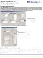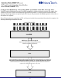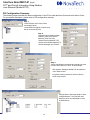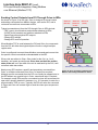
1
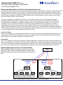
Interface Note #0907-01 R4
D/3® and Orion5r Integration Using Modbus over Ethernet (Modbus TCP)
Moving real-time data and control commands between the D/3 Process Automation System and field devices, through
the Orion5r Automation Platform, using Modbus TCP requires configuration know-how as well as an understanding of
the application and the specific field devices, field connections and data types. This note highlights key configuration
steps and provides background material to properly set up this interface.
It is also possible to establish a Modbus serial connection or a Modbus Plus connection between the Orion5r and the
D/3. In most installations, however, Modbus TCP will provide a more cost-effective and flexible solution at lower cost.
Contents:
Design and Application of the Orion Automation Processor……………………………………………………………………. 2
Typical Applications of Orion in Process Plants…………………………………………………………………………………... 2
Orion Models for Industrial Plans……………………………………………………………………………………………………...3
Summary of Interfaces Between Orion5r and D/3; Modbus Serial, Modbus Plus and Modbus TCP…………………….. 3
Details of Physical Ethernet Connections between Orion and D/3…………………………………………………………….. 4
Single/Dual Ethernet Application Guidelines………………………………………………………………………………………. 4
Orion Configuration Summary……………………………………………………………………………………………………….... 5
Default Files (Pick Lists) for Intelligent Electronic Devices (IEDs) Attached to Orion…………………………………….… 6
Bit / Byte Order Guidelines…………………………………………………………………………………………………………….. 8
Scaling Analog Data…………………………………………………………………………………………………………………….. 9
Handling Floating Point Numbers……………………………………………………………………………………………………. 11
Accuracy and Decimal Places………………………………………………………………………………………………………… 12
Accuracy of Power System Measurements………………………………………………………………………………………… 12
Configuration Guidelines – Presenting DDIO Input States to the D/3, Through Orion……………………………………… 13
D/3 Configuration Summary…………………………………………………………………………………………………………… 14
Sending Control Outputs from D/3 Through Orion to IEDs……………………………………………………………………… 15
Suggested Watchdog Circuit….......................................……………………………………………………………………………16
Definitions…………………………………………………………………………………………………………………………………. 17
1
Interface Note #0907-01 (cont)
D/3® and Orion5r Integration Using Modbus
over Ethernet (Modbus TCP)
Design and Application of the Orion Automation Processor
Orion is designed to provide real-time data from electrical substations and processes in response to requests from data
acquisition and control systems, such as the D/3. The data provided by Orion typically originates in attached “IEDs”
(Intelligent Electronic Devices) such as meters, protective relays and specialized controllers. Orion is also designed to
receive output commands (e.g. OPEN or CLOSE breakers) from manual operators or control systems, and to send
those commands to IEDs or output modules.
In electrical substations, the application of Orion is not considered critical in terms of ensuring operator safety,
protecting substation equipment or keeping the lights on. Other local equipment in the substation will OPEN and
CLOSE breakers automatically in response to electrical short circuits and other abnormalities. The real-time data
provided by Orion is important for operators to view power flows and breaker status, but typically not critical to
maintaining power flow or processes. Most modern substation IEDs can now store data with time stamps if Orion
ceases to poll for data. Most of the time, there is little data to report from a remote substation because the nature of the
electrical system operation is steady state. When electrical system disruptions occur due to storms, equipment failure
or unusually high load, then data is reported by IEDs and by Orion.
Logic and Control
Orion is not designed to be a Programmable Controller or to control real-time, critical equipment and processes, as it
goes through a 10-to-60 second reboot cycle when new configurations are loaded and activated. Orion does offer a
math and logic tool kit for data manipulation and simple control.
Redundancy
Orion is not designed for bump-less hot-failover redundant applications, because the primary substation application for
which it was designed is not critical. Two Orions can be configured in a cold back-up redundancy scheme (one powers
up and runs if the other goes down) which is described in this document. Orion is offered with up to two Ethernet ports,
but, in the current version, these are not designed to be redundant. This is further described within this document.
Typical Applications of Orion in Process Plants
Orion is typically applied in both plant process areas and in plant
substations. Figure 1 below describes the devices to which Orion is
attached and the typical inputs and outputs between Orion and the
PCM.
Process Areas
Real-Time
process data
inputs
Settings
outputs
PCM
Plant Substations
Breaker
Real-Time
Amps, Volts, TRIP/CLOSE
Watts, VArs, commands
etc inputs and settings
outputs
Orion
Orion
Serially-Accessed plant instrumentation using
serial protocols not supported by the D/3 system
(e.g. Keithley Moisture Meter, GE PH Meter, etc)
SeriallyAccessed
I/O Modules
Meters
Figure 1: Typical applications of Orion in process areas and in plant substations
2
Protective
Relays
Specialized
Controllers
Interface Note #0907-01 (cont)
D/3® and Orion5r Integration Using Modbus
over Ethernet (Modbus TCP)
Orion Models for Industrial Plans
Two Orion models are currently produced; the Orion5 and the Oiron5r. The Orion5r is offered with modifications
required for UL Listing, and the Orion5 is not. If UL Listing is required, the Orion5r should be specified.
The main differences between the Orion5 and the Orion5r are detailed in Table 1 below:
Size
# Serial Ports
IRIG-B Port*
# Ethernet Ports / Baud Rate
Built-In I/O
Orion5
6.4” wide
5.5” High
6.7” deep
up to nine
No
one optional
10BaseT (10MB)
Half-duplex
4in / 2out
Orion5r
19” rack mount
3.5” High (2RU)
13” Deep
up to 17
Yes
one optional port
10BaseT (10MB)
Half-duplex
4in / 4 out
or
two optional ports
10BaseT (10MB)/100BaseTX (100MB)
Auto-sensing
Full-duplex
Table 1: Orion models for industrial plants
*IRIG-B used to synchronize Orion’s clock to an accurate external GPS reference for accurate (down to 1mS) time-stamping of events
Summary of Modbus Interfaces (Serial, Plus and TCP) Between the D/3® and the Orion5r
Table 2 below summarizes the software and hardware required for the Orion5r-D/3 interface. This application note only
details the Modbus TCP interface.
Table 2: Modbus interfaces between the D/3 and Orion
3
Interface Note #0907-01 (cont)
D/3® and Orion5r Integration Using Modbus
over Ethernet (Modbus TCP)
Single/Dual Ethernet Application Guidelines
The Orion5r is available with two Ethernet options; single Ethernet or Dual Ethernet, each using an RJ-45 style
connector supporting Ethernet twisted pair. The single Ethernet port option only supports 10MB (10BaseT) while
the Dual Ethernet option supports either 10MB or 100MB (10BaseT/100BaseTX).
Many D/3 users prefer to set up Ethernet networks and devices as all 100MB full-duplex, as this provides the
highest level of performance and reduces the chances of experiencing communication failure. Half-duplex
reduces throughput, and mixing 10MB and 100MB Ethernet devices requires Ethernet switches to be configured
in “auto-sensing” mode. Auto-sensing creates additional latency which can result in comm failure between PCMs.
For this reason, it is preferable to specify Dual Ethernet full-duplex 100MB Orion5rs in some plants rather than the
single Ethernet Orion5 or Orion5r which are both limited to half-duplex 10MB.
In this current Orion5r model, the two Ethernet ports are not designed to be redundant; instead they must be
assigned different Ethernet subnets and must not reside on the same network (this architecture was requested by
Utility clients to ensure separation between the Ethernet network in the substation and the Ethernet network from
the substation to the remote polling location). See Figure 2 below.
In dual Ethernet Orion applications, it is suggested to use one Ethernet network for handling real-time data
between Orion and the PCM, and to use the second Ethernet network to connect to a networked PC for remote
configuration and diagnostics. See Figure 3 below.
RJ45 Style 10BaseT/100BaseTX
Rear View of Orion5r
Subnet #1
Subnet #2
Switch / Media
Converter as
required by the
application
Real-Time data
to and from PCM
To Configuration
and Diagnostic PC
Figure 3: Suggested physical Ethernet connection between Orion and the PCM
Figure 2: NCD configuration screen for dual
Ethernet. Note different subnets required.
4
Interface Note #0907-01 (cont)
D/3® and Orion5r Integration Using Modbus
over Ethernet (Modbus TCP)
Orion Configuration Summary
All Orion configuration is performed offline using a free-issue software program named NovaTech Communications
Director or NCD. In order to understand how Orion is configured, it is important to first understand how Orion is typically
applied.
Master #1 Master #2 Master #3
Orion serves as a protocol converter and data concentrator in
most industrial applications. In these roles, Orion reads data from
attached IEDs and presents these data to attached Masters.
As graphically depicted in Figure 4 to the right, Orion typically reads
only a portion of the available data from attached Slave IEDs, as
many IEDs contain hundreds or thousands of points. Orion normally
uses preconfigured pick lists or “Default Files” to simplify the
selection of which points to read. If a Default File is not available,
selected points can be typed into the configuration screen. The
following section of this application note further describes Default
Files.
A portion of the data, or all of the data read from Slaves, can be
presented to one or more Masters. Even though the data may have
come from a Slave using one protocol, it can be presented to a
Master in a different protocol. The protocol translation is transparent.
Independent buffers for each Master are maintained to ensure
proper execution of control commands and data counters. Also, the
data presented to the Master can be scaled and numbered as
desired by the user.
(D/3 DCS)
(other PLC
or DCS)
(other)
Masters read these data from Orion
Orion is Slave to Master(s)
Orion is Master to Slaves
Orion reads data from Slaves
Slave
Slave
Slave
IEDs
IEDs
IEDs
(Meters, Protective Relays, Instruments)
Figure 4: Orion reading data from Slaves and
presenting data to Masters
Basic Orion configuration steps include:
1) Install NCD on your PC. All Orions are shipped with an NCD CD, plus NCD can
always be downloaded from the Orion User Support Site. A Username and
Password are required; please call BJ Weil at 913-451-1880 to obtain if you do
not have one.
2) Open NCD
3) Configure “General” parameters; user name, password, forcing points, etc.
4) Configure Orion hardware model, IP addresses, etc.
5) Select serial port (can be RS232, RS485 or serial Fiber Optic)
Select protocol, either Master or Slave for this port
Configure serial port parameters: baud rate, address etc.
If Master, select IED company and IED model, then select points to be read
If Slave, select points to be presented to the Master
If desired, configure points numbers and scaling parameters
6) Configure IRIG-B time parameters (if present)
7) Configure Network port (Ethernet). Follow same steps as in #4 above
8) Configure “Add Ons” (if present), which are Orion options for archiving
data, serving out web pages for Sequence of Events and Alarms and other options
9) Configure Hardware I/O built into Orion
10) ATC and DA (if present) are specialized application for Utility customers and OEMs
11) Configure Logic (if present)
5
Figure 5: Configuration selections for
Orion within NCD. Selections are based
upon options ordered
Interface Note #0907-01 (cont)
D/3® and Orion5r Integration Using Modbus
over Ethernet (Modbus TCP)
Default Files
In order to simplify the selection of values to be read from an IED, NovaTech provides pre-configured Default Files or
“pick lists” for hundreds of commonly-used IEDs. These Default Files are spreadsheets that contain the addresses and
names of the data points, the high / low range of the value and other communication parameters unique to the device.
Each IED and each protocol require Default Files (a GE F60 protective relay with Modbus protocol uses a different
Default File than the F60 relay with DNP3 protocol). Default Files are provided as part of the configuration program for
the Orion5r, NovaTech Communications Director or NCD.
More about Default Files:
1) The Default File is developed based upon what the IED
manufacturer states is present in their standard
communication map in their IED, and is typically obtained
from the IED user manual and other documentation. If this
documentation is inaccurate, or if the points map has been
modified by the user, the Default File will also have to be
modified.
IED Names and Models
Serial “Default” comm parameters
2) Creating and Editing Default Files can be accomplished
by NovaTech Engineers or by the user. An application note
is available detailing how each spreadsheet row and
column should be filled in. When complete, the new
Default File is loaded in the “Defaults” directory within
NCD.
Point names, data types, ranges
3) As a policy, NovaTech will edit and develop new Default
Files at no extra charge to the user. We do request at least
two to three weeks advance notice, preferable while the
Orion is on order and prior to delivery. The Default Files for
some protocols and IEDs can be complicated and may
require testing with the IED prior to submission to the user;
we may require the user to loan us the IED for a week. All
Default Files become part of the NCD program available to
all users.
4) Default Files for nearly all IEDs commonly applied in
Utility substations are available in NCD. However, fewer
Default Files exist for the IEDs applied in Industrial
substations and process applications.
Figure 6: Portion of Default File for eight Bitronics Meters with Modbus
protocol
List of all points available to
be read from the Bitronics
Meter. These points are
from the Default File.
Points selected to be read
Figure 7: NCD “Inputs” configuration screen
6
Interface Note #0907-01 (cont)
D/3® and Orion5r Integration Using Modbus
over Ethernet (Modbus TCP)
Default Files (continued)
5) If a Default File is not available, points from an IED can still be configured to be read. Within NCD, the user can
always select “New” and then manually type in the name and address of the point to be read. See Figures 8 and 9
below.
Figures 8 and 9 showing configuration of a new point for an
IED for which there is no Default File
7
Interface Note #0907-01 (cont)
D/3® and Orion5r Integration Using Modbus
over Ethernet (Modbus TCP)
Bit / Byte Order Guidelines – Modbus Protocol
The arrangement and numbering of bits and bytes transferred with the Modbus Protocol varies from one
implementation to another.
NovaTech conforms to the original Modicon standard where the first bit in a register is #1 (MSB) and the last is
#16 (LSB).
When Orion is configured to read data from a Modbus Slave, one of the configuration parameters is the “Dword” or
“double word” order of the data. When NovaTech engineers develop the Default Files for an IED, they include the
Dword order as part of the Default File. If you use a pre-configured Default File provided by NovaTech, you should be
able to use the default setting for Dword order. See Figure 10 below for an example of the Dword and other settings for
an Electro-Industries Nexus 1250 Meter.
Figure 10: Selection of “Dword” (“double-word”) order for reading data from a typical Modbus Slave IED – Nexus 1250 Meter
When data is presented to a Modbus Master, such as the PCM, the Dword order can be selected. When presenting
data to the PCM, normally you would select “Modicon” Dword order. See Figure 11 below for a configuration example.
For the four-byte, “double word”: 01 02 03 04
the order would be:
04 03 02 01 Intel
02 01 04 03 Modicon
01 02 03 04 Motorola
When presenting data to the D/3, normally you
will select “Modicon” Dword order.
Figure 11: Selection of “Dword” (“double-word”) order for presenting data to a Modbus Master
8
Interface Note #0907-01 (cont)
D/3® and Orion5r Integration Using Modbus over
Ethernet (Modbus TCP)
Analog Data Scaling
The data values retrieved from the devices attached to the Orion may be not be “scaled” properly for presentation
to the D/3. Orion can convert data values as shown in the examples in this section.
When scaling analog data, either of the following two situations may exist:
Scaling Situation #1 - Real-Time Measurement Can Be Made
In this case, a real-time measurement can be made of actual value being read by Orion from the IED, or the actual
value is presented on the IED faceplate. This real value can be correlated with the numerical value presented by
the IED. Scaling can then be set up accordingly to present the real value to the D/3 system as desired.
Scaling Example A
See screen capture to the right. Orion reads Phase
A-N voltage from the Nexus 1250 Meter. The meter
returns a value of 3677. This is 3677 counts or
5.610742% of full scale (scale is 0-to-65535). This
corresponds to a value of 123VAC as measured by
a volt meter.
We want the D/3 to read 123VAC, not 3677. We
can present 123 to the D/3 by making 123
5.610742% of a new scale. See arithmetic below:
123 is 5.610742% of what number?
123 = .05610742x
solve for x = 2192
If we present Phase A-N voltage to the D/3 in a
range from 0-2192, the value will be scaled
properly, and the D/3 will read 123VAC. See Figure
13 below showing configuration screen for data
Figure 12: Screen capture showing real-time data values being read by Orion from
presented to the PCM.
a Nexus 1250 meter
This is the number
we changed to
modify the data
values presented to
the PCM
Figure 13: NCD Configuration screen for data points presented to the Modbus Master by the Orion Slave
9
Interface Note #0907-01 (cont)
D/3® and Orion5r Integration Using Modbus
over Ethernet (Modbus TCP)
Analog Data Scaling (continued)
Scaling Example B
See screen capture to the right. Orion reads Phase A
Amperes from the Bitronics Meter. The meter returns
a value of 2282. This is 2282 counts or 11.474609%
of full scale (scale is 2047-to-4095 where 2047
equals 0 Amperes and 4095 equals the maximum
Amperes able to be presented to the meter using the
selected field transformers. See page xx for a
description of the transformers used in power system
measurements). This corresponds to a value of 92.5
Amperes as displayed on the meter faceplate.
We want the D/3 to read 93 Amperes (non-decimal
integer value), not 2282. We can present 93 Amperes
to the D/3 by making 93 11.474609% of a new scale.
See arithmetic below:
93 is 11.474609% of what number?
93 = .11474609x
solve for x = 810
Figure 14: Screen capture showing real-time data values being read by Orion
from a Bitronics meter
If we present Phase A Amperes to the D/3 in a range
from 0-to-810, the value will be scaled properly, and
the D/3 will read 93 Amperes. See Figure 15 below
showing configuration screen for data presented to
the PCM.
This is the number
we changed to
modify the data
values presented to
the PCM
Figure 15: NCD Configuration screen for data points presented to the Modbus Master by the Orion Slave
10
Interface Note #0907-01 (cont)
D/3® and Orion5r Integration Using Modbus
over Ethernet (Modbus TCP)
Analog Data Scaling (continued)
Scaling Situation #2 – No Real-Time Measurement Can Be Made
In this case, it is not possible to make a real-time measurement of the actual value being read by Orion from the IED,
and the value is not displayed on the IED faceplate. In this situation, it is necessary to review:
1) The primary power connections (CTs and PTs) to be made to the IED
2) The IED manufacturer’s documentation to determine how measured values are presented
Background – CTs and PTs
Three phase
distribution feeder
Three voltage and three current
connections (one to each phase)
All power system IEDs require primary power values to be “stepped down” to
levels which can be measured. This is most often accomplished through the
use of current transformers (CTs) that step currents down to 1A or 5A per
phase, and voltage/potential transformers (PTs) that step voltage down to
120VAC per phase. All power system values; Volts, Amps, frequency, VArs,
Watts, harmonics, etc. can all be calculated by the IED based on these CT and
PT inputs.
CTs and PTs are purchased in various ratios to present measurable values to
the IED; e.g., the higher the primary voltage the greater the CT ratio to present
a measurable value.
Power Meter
or
Protective Relay
If we are to understand the value presented by an IED, we need to know the CT
and PT ratios.
IED Manufacturer Documentation
Although some IEDs present power system values in engineering units – in real quantities as measured; 200 Amps,
12,000V, etc - most IEDs present values in counts which have to be correlated with the real value. A formula is usually
provided in the user documentation, or can be obtained from application engineers, to perform the conversion.
It is also important to understand the data type(s) used by the manufacturer. Smaller numbers are usually presented as
single-register integers and larger numbers in two-register integers – with high and low register – or in floating point
format. VArs and Watts are reported with a plus (+) or minus (-) sign based upon the direction of flow, and are reported
various ways.
For example, the Bitronics MultiComm 3-Phase Multifunction Digital Meter reports VArs in the range from 0-to-4095,
with 0 being -1000 VArs, 2047 being 0 VArs and 4095 as +1000 VArs. Note these VAr measurements are at the meter,
on the CT and PT secondaries. The formula for conversion:
Actual VArs (per phase) =
Value – 2047
x 1000 x PTratio x CTratio
2048
This means that a value of 1500 returned by the Bitronics Meter, with a PT ratio of 200 and CT ratio of 40, would
calculate to:
= 1500 - 2047 x 1000 x 200 x 40 = - 2,136,719 VArs or -2.14 MVArs
2048
Handling Floating Point Numbers
Some IEDs present data in two-register floating point format to Orion. These floating point analog numbers can be
presented by Orion (in Modicon Dword order) and directly read into the D/3 using the “FLT” conversion type (IEEE 754
32-bit floating point). See D/3 documentation for more detail.
11
Interface Note #0907-01 (cont)
D/3® and Orion5r Integration Using Modbus
over Ethernet (Modbus TCP)
Accuracy and Decimal Places
In the scaling example on Page 10, note that the Ampere value presented to the D/3 (93 Amperes) was rounded to the
nearest Ampere with no decimal point reported. If a decimal place is desired, making the value 92.5 Amperes, change
the scaling from 0-to-810 to 0-to-8100, and the value will be presented to the D/3 as 925. This in turn can be configured
in the D/3 to be displayed as 92.5. See Figures 16 and 17 below for configuration guidelines.
Change this number from
810 to 8100 to present an
extra digit to the D/3
(present 925 instead of 93).
Figure 16: NCD Configuration screen for data points presented to the Modbus Master
EGU must be 810
HIGOOD will use 8100 to display
additional significant digits.
Figure 17: Abbreviated WinMod Screen Capture
Accuracy of Power System Measurements
The accuracy of power system measurements is based upon the accuracy of the current and voltage transformers
used to convert primary values to measurable values (e.g., 1000 Amps to 5 Amps, or 12,000 Volts to 120 Volts). It is
also based upon the analog-to-digital conversion accuracy of the meter or relay. With the exception of revenue meters,
most power meters present data accurate to +/- 0.25% to +/- 1%. Protective relay measurements are typically not as
good, down to +/- 2%.
12
Interface Note #0907-01 (cont)
D/3® and Orion5r Integration Using Modbus
over Ethernet (Modbus TCP)
Configuration Guidelines – Presenting DDIO Input States to the D/3, Through Orion
The DDIO module (Distributed Discrete I/O module) is available in in thee combination of inputs and outputs: 24in,
16in/8out or 8in/16out. Orion communicates with the DDIO using DNP3.0, a common protocol used in the utility
industry. If these input states are required by the D/3, they can be presented in the Modbus protocol as bits, coils, or
bits packed into registers.
When 24 input states are required by the D/3, and they are desired to be presented as bits packed into registers, the
following numbering conventions are used
Inputs #1 through #24
1
2 3 4
5
6
7
8
9 10 11 12 13 14 15 16 17 18 19 20 21 22 23 24
24-in DDIO
DNP Binary Inputs #0 through #23
(Input circuit #1 is DNP3.0 binary input point #0,
circuit #2 is DNP binary point #1)
Orion
Any two Modbus registers with any bits (representing inputs) placed in any location in
the registers. NCD configuration software enables you to place bits wherever desired.
Note: NovaTech Orion conforms to the original Modicon standard where the first bit in a
register is #1 (MSB) and the last is #16 (LSB).
PCM
13
Interface Note #0907-01 (cont
D/3® and Orion5r Integration Using Modbus
over Ethernet (Modbus TCP)
D/3 Configuration Summary
The following steps describes the basic configuration of the D/3 to read data from Orion and write data to Orion.
For a complete description, please refer to D/3 configuration manuals.
Step 1:
-Select PCM to which Orion will be
connected (LIQ1A)
-Select Ethernet module to which Orion
will be connected (ETH0)
Step 2:
-Name the Orion Ethernet Node
(ORION_SUB1) and Orion IP
Address (10.80.100.105)
-Select Protocol (Modbus TCP)
-Define Orion Modbus Address (1)
-Define Messages and Timeout
Step 3:
-Define the Modbus commands and registers to read
in Orion and written to in Orion. In this example:
-100 registers, starting at 400001 will be read from
Orion each second
-2 registers, starting at 400101 will be written to
Orion every second
Configuration to left shows what we have
configured above. The PCM will read
data from Orion and write data to Orion
as defined here.
14
Interface Note #0907-01 (cont)
D/3® and Orion5r Integration Using Modbus
over Ethernet (Modbus TCP)
Sending Control Outputs from D/3 Through Orion to IEDs
As shown in Figure 18 to the right, Orion is designed to accept control
and setting commands from Master devices, such as the D/3, and to
route and convert these commands to IEDs.
Typical commands sent from the D/3 through Orion to IEDs include:
-TRIP (open) circuit breakers and switches attached to IEDs
-CLOSE circuit breakers and switches attached to IEDs
-Open/Close other physical IED outputs
-Change IED settings
-Change IED mode of operation
When Modbus TCP is used between the D/3 and Orion, the commands
from the D/3 will either be single/multiple coil write or single/multiple
register write.
Master #1
(D/3 DCS)
Master #2
(other PLC
or DCS)
Master #3
(other)
New
TRIP Setting CLOSE
New CLOSE TRIP
Setting
Orion is configured to accept these Modbus commands and convert into
the specific control commands understandable to the IED.
When coils are written to Orion, Orion looks for the 0-to1 or 1-to-0
transition, and reacts as configured. Orion does not hold the written
state of the coil, so if the state of the coil is read back by the D/3, it will
not reflect what was written.
Nearly every IED requires a specific and proprietary command from
Orion, or multiple commands from Orion, to respond as required.
Although control commands from the D/3 can usually be mapped over to
the IED without any special logic in Orion, sometimes logic is required.
For example, some IEDs require a command to close and a command to
open with a specific duration in between (e.g., 0.5 seconds) in order for a
proper breaker TRIP to occur. Typically, the D/3 will write one command
to Orion and Orion will contain logic to send the close-open sequence to
the IED.
15
Slave
Slave
Slave
IEDs
IEDs
IEDs
(Meters, Protective Relays, Instruments)
Figure 18: Orion accepting commands from
Masters and sending commands to Slaves
Interface Note #0907-01 (cont)
D/3® and Orion5r Integration Using Modbus
over Ethernet (Modbus TCP)
Suggested Watchdog Circuit
It is suggested that watchdog logic be created to monitor communication between the D/3 and the Orion such
that action can be taken in the event of communication failure. One common approach is to create a Digital
Device in the D/3 that toggles bits in the Orion. If the toggling stops after a predefined amount of time, shutdown
logic or other logic can be initiated on either side if necessary and additional process alarms can be triggered in
the D/3. The diagram below further describes how this logic could be set up.
PCM
(Master)
PCM Logic:
Create free-running timer to initiate comm fail if not reset in x
seconds
Read coil 000258 from Orion. The value will be either a 1 or a 0
If coil 00258 is different from the previous reading, reset timer
If coil 00258 is the same as the previous value, do nothing
Invert the state of the coil (0-to-1 or 1-to-0) and write to coil 00257 in
Orion
If communications if good, the timer should continually be reset and
should not time out.
Coil 00257
Coil
00258
Orion
(Slave)
Orion Logic:
Create free-running timer to initiate comm fail if not reset in x seconds
Read internal coil 000257. The value will be either a 1 or a 0
If coil 00257 is different from the previous reading, reset timer
If coil 00257 is the same as the previous value, do nothing
Initiate Communication Failure actions if timer times out
If communications if good, the timer should continually be reset and
should not time out.
Note that the inversion can be done in either the Orion or the PCM,
but not in both.
16
Interface Note #0907-01 (cont)
D/3® and Orion5r Integration Using Modbus
over Ethernet (Modbus TCP)
Definitions
Bit / Byte / Word
1 bit: a single digit number in base-2; in other words, either a 1 or a zero - the smallest unit of computerized data.
Bandwidth is usually measured in bits-per-second.
1 byte =
8 bits
1 word =
16 bits
2 bytes
1 double-word =
(single-precision floating point
or integer)
32 bits
4 bytes
2 words
1 double-precision word =
64 bits
8 bytes
4 words
DNP3
An IEEE standard for communication between computers within the substation and from the substation to
SCADA. DNP3 is a messaging system with objects and control commands specifically defined to pertain to
monitor and control substation equipment. Like Modbus, DNP3.does not define the physical port, the
communications medium, or the baud rate. Unlike Modbus, DNP3.does define portions of the application, such as
setting the time, reporting by exception and establishing specific control sequences for circuit breakers. DNP3 can
be transmitted over an Ethernet / TCP communications network.
Floating Point (IEEE 754)
The IEEE Standard for Binary Floating-Point Arithmetic (IEEE 754) is the most widely-used standard for floating
point computation. The standard defines formats for representing floating-point numbers together with a set of
floating-point operations that operate on these values. IEEE 754 specifies four formats for representing floatingpoint values: single-precision (32-bit), double-precision (64-bit), single-extended precision (≥ 43-bit, not commonly
used) and double-extended precision (≥ 79-bit, usually implemented with 80 bits). Only 32-bit values are required
by the standard; the others are optional. For complete treatment, see http://en.wikipedia.org/wiki/IEEE_floatingpoint_standard
Two examples of single-precision 32-bit floating point numbers:
17
Interface Note #0907-01 (cont)
D/3® and Orion5r Integration Using Modbus
over Ethernet (Modbus TCP)
Definitions (continued)
Half-duplex and Full-duplex (on Ethernet)
Half-duplex works optimally only if one device is transmitting and all the other devices are receiving, otherwise,
collisions occur. When the collisions are detected, the devices causing the collision wait for a random time before
retransmitting. This means that at half duplex, Ethernet throughput is limited by the need to retransmit data when
collisions occur. Half-duplex is the most common transmission method and is adequate for normal workstation and
PC connections. Full-duplex provides dual communication on a point-to-point connection and allows each device to
simultaneously transmit data and receive data on a connection. Full-duplex mode is typically used to connect to
other switches or to connect fast access devices such as workgroup servers.
Receive
Half-duplex with transmit and receive on a single pair
Transmit
Receive
Full-duplex with transmit on one pair and receive on
another pair. Note both pairs are inside the same
“Ethernet” cable.
Transmit
IED
Common acronym for an Intelligent Electronic Device such as a meter, protective relay or specialized controller
used in the electrical system.
RS-232
A recommended industry standard (“RS”) for transmitting data. RS-232 allows Full Duplex transmission, which
means there are separate transmit and receive signal lines enabling data flow in both directions simultaneously.
RS-232 uses an unbalanced signal mode, meaning a voltage down a single wire is used to transmit/receive binary
1 and 0. Often used for telemetry control systems where long cable runs are not required (less than 100 feet).
Most devices use a DB-9 connector for RS-232 communication, either DB-9F (female), DB-9M (male), although
other connector types (DB-25, RJ-11, screw terminal) are used.
The DB-9M male pins are designated as shown below. DB-9F are opposite:
..
RS-485
A recommended industry standard which permits data interchange on multidrop networks of up to 32 nodes using a
single twisted pair cable. In order for this protocol to be used, each device on a network must be addressable.
Similar to RS-232 but uses a balanced signal mode. A balanced signal mode utilizes a pair of wires where a
voltage difference is used to transmit/receive binary information. A balanced voltage signal level travels faster and
much longer distances than an unbalanced type (up to 1500 feet). Used extensively for telemetry control systems.
18