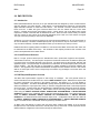
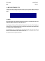
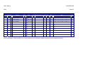
1
M6xx Measurement Centre and Transducer DNP3 Manual M6xx Measurement Centre and Transducer Publication Reference: M6xxD/EN/M/B © 2014. ALSTOM, the ALSTOM logo and any alternative version thereof are trademarks and service marks of ALSTOM. The other names mentioned, registered or not, are the property of their respective companies. The technical and other data contained in this document is provided for information only. Neither ALSTOM, its officers or employees accept responsibility for, or should be taken as making any representation or warranty (whether express or implied), as to the accuracy or completeness of such data or the achievement of any projected performance criteria where these are indicated. ALSTOM reserves the right to revise or change this data at any time without further notice. M6xxD/EN/M/B GRID DNP3 Manual M6xxD/EN M/B M6xx Page 1 TABLE OF CONTENTS CERTIFICATION ..........................................................................................................................................3 INSTALLATION AND MAINTENANCE .......................................................................................................3 ASSISTANCE ...............................................................................................................................................3 COPYRIGHT NOTICE ..................................................................................................................................4 SAFETY SECTION .......................................................................................................................................4 1.0 DNP INTERFACE ...................................................................................................................................5 1.1 Description .........................................................................................................................................5 1.2 DNP Address .....................................................................................................................................5 1.3 Transaction Timing ............................................................................................................................5 1.4 Object Format ....................................................................................................................................5 1.4.1 DNP3 Calculation-Type Codes ..................................................................................................6 1.5 Configuration .....................................................................................................................................9 1.5.1 Setting CT and VT Ratios ..........................................................................................................9 1.5.2 Resetting Energy and Demands ................................................................................................9 1.5.3 Tag Registers ...........................................................................................................................10 1.6 Converting Data to Engineering Units .............................................................................................10 1.7 Primary Units ...................................................................................................................................12 1.8 Data Sets and Data Types ..............................................................................................................14 1.8.1 Configuring the Class-0 Response ..........................................................................................14 1.8.2 Configuring Class-1, Class-2 and Class-3 Events ..................................................................15 1.9 Health Check ...................................................................................................................................16 1.10 Heartbeat State Counter ................................................................................................................16 1.11 Meter ID Register ..........................................................................................................................16 1.12 Custom Points Lists .......................................................................................................................16 2.0 DNP PROTOCOL ................................................................................................................................20 2.1 Introduction ......................................................................................................................................20 2.2 Overall Protocol Structure ...............................................................................................................20 DNP3 Manual M6xx M6xxD/EN M/B Page 2 2.3 DNP Request/Response Overview .................................................................................................20 3.0 DNP3 OVER ETHERNET (TCP) .........................................................................................................21 3.1 DNP/IP .............................................................................................................................................21 4.0 DNP3 EVENTS OVERVIEW ...............................................................................................................22 4.1 ANALOGUE CHANGE EVENTS .....................................................................................................22 4.2 FROZEN COUNTER EVENTS........................................................................................................23 4.3 BINARY INPUT CHANGE EVENTS ...............................................................................................23 Appendix A: Bitronics Legacy DNP3 Point Assignments ....................................................................24 Appendix B: DNP3 Configuration Parameters ......................................................................................31 Appendix C: DNP3 Device Profile ..........................................................................................................36 DNP3 Manual M6xx M6xxD/EN M/B Page 3 CERTIFICATION Alstom Grid certifies that the calibration of the products is based on measurements using equipment whose calibration is traceable to the United States National Institute of Standards Technology (NIST). INSTALLATION AND MAINTENANCE Alstom Grid products are designed for ease of installation and maintenance. As with any product of this nature, installation and maintenance can present electrical hazards and should be performed only by properly trained and qualified personnel. If the equipment is used in a manner not specified by Alstom Grid, the protection provided by the equipment may be impaired. ASSISTANCE For assistance, contact Alstom Grid Worldwide Contact Centre: http://www.alstom.com/grid/contactcentre/ Tel: +44 (0) 1785 250 070 M6xx Manual Set M65x User Manual M6xx Modbus Protocol Manual M6xx DNP3 Protocol Manual DNP3 Manual M6xxD/EN M/B M6xx Page 4 COPYRIGHT NOTICE This manual is copyrighted and all rights are reserved. The distribution and sale of this manual is intended for the use of the original purchaser or his agents. This document may not, in whole or part, be copied, photocopied, reproduced, translated or reduced to any electronic medium or machinereadable form without prior consent of Alstom Grid, except for use by the original purchaser. This manual incorporates information protected by copyright and owned by Bitronics LLC, 261 Brodhead Road, Bethlehem, PA 18017. Copyright © 2014 Bitronics, LLC. All rights reserved. The product described by this manual contains hardware and software that is protected by copyrights owned by one or more of the following entities: Bitronics, LLC, 261 Brodhead Road, Bethlehem, PA 18017 Schneider Automation, Inc., One High Street, North Andover, MA 01845 Triangle MicroWorks, Inc., 2213 Middlefield Court, Raleigh, NC 27615 Freescale Semiconductor, Inc., 6501 William Cannon Drive West, Austin, TX 78735 gzip inflation uses code Copyright 2002-2008 Mark Adler inarp uses WinPcap, which is Copyright 1999-2005 NetGroup, Politecnico di Torino (Italy), and 20052010 CACE Technologies, Davis (California). TRADEMARKS The following are trademarks or registered trademarks of Alstom Grid: Alstom Grid the Alstom Grid logo The following are trademarks or registered trademarks of Bitronics LLC: The Bitronics logo Bitronics The following are trademarks or registered trademarks of the DNP User's Group: DNP DNP3 The following are trademarks or registered trademarks of Schneider Automation, Inc.: MODSOFT Modicon Modbus Plus Modbus Compact 984 PLC SAFETY SECTION Please refer to the M65x or M66x User Manual for information regarding safety, installation, commissioning and decommissioning. DNP3 Manual M6xxD/EN M/B M6xx Page 5 1.0 DNP INTERFACE 1.1 Description The DNP network is a "MASTER" to "SLAVE" network; that is to say, one node asks a question and a second node answers. A NODE is a DNP device (RTU, Computer, M65x, M66x, etc.) that is connected to the network. Each DNP NODE has an ADDRESS in the range of 0 to 65519, and it is this address that allows a MASTER to selectively request data from any other device. DNP uses the address range 6553365536 for broadcast functions. Broadcast requests never generate DNP responses. The DNP implementation in the M6xx conforms to DNP3 specifications as defined by DNP.org (derived from the Harris IED (Intelligent Electronics Devices) implementation guidelines). Data obtained by the DNP READ CLASS 0 command is configurable. Individual items can also be read using READ BINARY OUTPUT STATUS or READ ANALOGUE INPUT or READ COUNTER or READ ANALOGUE OUTPUT STATUS or READ BINARY INPUT or READ FROZEN COUNTER commands. The Energy values can be reset to zero by issuing the DIRECT OPERATE, DIRECT OPERATE NO ACKNOWLEDGE, or SELECT BEFORE OPERATE by using the CONTROL RELAY OUTPUT BLOCK object. The Demand values can be reset by issuing the same DIRECT OPERATE, DIRECT OPERATE NO ACKNOWLEDGE, or SELECT BEFORE OPERATE command to the other points of this object. M6xx ANALOGUE OUTPUTS have two read/write values: Tag and Tag1. They can be changed by issuing DIRECT OPERATE, DIRECT OPERATE NO ACKNOWLEDGE, or SELECT BEFORE OPERATE by using the ANALOGUE OUTPUT BLOCK object. Due to the limited number of FLASH write cycles, they SHOULD NOT be written continuously. Four legacy values are also presented. They are CT Scale Factor Normalized Ratio and Divisor, and VT Scale Factor Normalized Ratio and Divisor. They are derived from the PT scale and CT scale configured through the browser interface. The SELECT BEFORE OPERATE arm timeout value is configurable from zero to 64 seconds. 1.2 DNP Address The serial port in the M65x can be set up to be RS-232 or RS-485, and support baud rates from 9600 to 115200. Configuring the Serial Ports can be accomplished by using the display buttons or via a standard web browser while setting the address is done via a web browser only. Each DNP instrument responds to a single destination address in the range 0-65519. Each instrument on a DNP link must have a unique address. M6xx meters will allow any of the 65520 addresses to be selected. DNP instruments also use a BROADCAST address range of 65533-65535. Requests sent to a BROADCAST address cause the instrument to execute the function but not generate a response. 1.3 Transaction Timing M6xx meters complete a set of calculations approximately every 100ms. Incoming messages are parsed every 50ms. 1.4 Object Format M6xx meters report all static measurements via the use of three static objects. These objects include COUNTER (object 20, variations 1, 2, 5 and 6), ANALOGUE INPUT (object 30, variations 1, 2, 3 and 4) and BINARY INPUT (object 2, variations 1 and 2). These objects are read only and cannot be modified by DNP MASTER devices. ANALOGUE OUTPUT STATUS (object 40, variation 2) can read CT and VT configuration information and two tag registers. ANALOGUE OUTPUT BLOCK (object 41, variation 2) can be used to write the Tag/Tag1 register through DNP. Due to the limited number of FLASH write cycles, Tag/Tag1 SHOULD DNP3 Manual M6xx M6xxD/EN M/B Page 6 NOT be written continuously. Pseudo output points (such as demand and energy resets) are reported using the BINARY OUTPUT STATUS (object 10, variation 2). M6xx meters are capable of reporting ANALOGUE CHANGE EVENTS (object 32, variations 1 through 4). Any ANALOGUE INPUT can be configured to report as a CLASS-1, CLASS-2, or CLASS-3 ANALOGUE CHANGE EVENT. Point, Class, Analogue Deadband Values and Object Variation are all selectable by use of the Ethernet service port and web browser. The default Object Variations are selectable by Object (not by point). All ANALOGUE CHANGE EVENTS can be configured to report with or without time. M6xx meters support frozen counter events (object 21, variations 1, 2, 5 and 6 which are 16 or 32-bit with or without time). M6xx meters support one BINARY INPUT (object 1, variations 1 and 2) and one BINARY INPUT CHANGE event (object 2, variations 1, 2, and 3). The single binary input is derived from the OR of the bits from the Health status word. The DNP protocol allows each device to determine the best method of data transfer. The M6xx meters support this by selecting the most appropriate response variation when either the requested variation is 0 or a CLASS-0 read is requested. Both COUNTER and ANALOGUE INPUT objects allow optional flags to be used. If a value is requested as variation 0, the M6xx meter responds as selected with the default variation selected through the browser. When reading objects, the Health Check point (object 30, point 0) should always be read and checked before interpreting data, since some failure modes will cause erroneous data to be presented (See Section 1.8). The majority of the points are represented in Normalized 2's complement format. For conversion of the point data into engineering units, please refer to Section 1.6. Appendix A provides the Legacy or Bitronics Legacy Fixed (BiLF) point set used in the M6xx. NOTE: Unless otherwise specified, all points are READ ONLY. 1.4.1 DNP3 Calculation-Type Codes The DNP3 Type codes for Optimal Resolution that are applicable to the point assignments in the appendix tables are highlighted within the following Calculation Type table: DNP3 Manual M6xx Page 7 Type Description T1 Unsigned 16-Bit Integer T2 Signed 16-Bit Integer - 2's Complement - Saturation 10 Float Value = ( (Integer Value) / 32768) * Scale * 10) Example: 5.0 A stored as 16384 when Amp Scale = 1:1 T3 Signed 16-Bit Integer - 2's Complement - Saturation 15 Float Value = ( (Integer Value) / 32768) * Scale * 15) Example: 150 A stored as 16384 when Amp Scale = 20:1 T4 Signed 16-Bit Integer - 2's Complement - Saturation 150 Float Value = ( (Integer Value) / 32768) * Scale * 150) Example: 119.998 V stored as 26214 when Volt Scale = 1:1 T5 Signed 16-Bit Integer - 2's Complement - Saturation 1500 Float Value = ( (Integer Value) / 32768) * Scale * 1500) Example: -750.0 W stored as -16384 when Volt Scale = 1:1, Amp Scale 1:1 T6 Signed 16-Bit Integer - 2's Complement - Saturation 4500 Float Value = ( (Integer Value) / 32768) * Scale * 4500) Example: -90.0 kW stored as -8192 when Volt Scale = 20:1, Amp Scale 4:1 T7 Signed 16-Bit Integer - 2's Complement - 3 Decimal Places Example: -12.345 stored as -12345 T8 Signed 16-Bit Integer - 2's Complement - 2 Decimal Places Example: 123.45 stored as 12345 T9 Signed 16-Bit Integer - 2's Complement -1 Decimal Place Example: -1234.5 stored as -12345 T10 Unsigned 16-Bit Integer - Normalized Ratio ratio = (Normalized Ratio / Ratio Divisor) Example : 1.234, 12.34, 123.4, and 1234 are all stored as 1234 T11 Unsigned 16-Bit Integer - Ratio Divisor ratio = (Normalized Ratio / Ratio Divisor); valid Ratio Divisors are 1,10,100,1000 Example: X.XXX stored as 1000, XX.XX stored as 100, XXX.X stored as 10 T12 Signed 16-Bit - 2's Complement - Saturation 2 Gain Value = Integer Value /16384) Example: -0.250 stored as -4096 T13 M6xxD/EN M/B Unsigned 16-Bit Integer - 12 Bit Offset Binary - Saturation 10 Float Value =( (Integer Value - 2047) / (2048) ) * Scale * 10 DNP3 Manual M6xx Type Page 8 Description Example: 5.0 A stored as 3071 when Amp Scale 1:1 T14 Unsigned 16-Bit Integer - 12 Bit Offset Binary - Saturation 150 Float Value =( (Integer Value - 2047) / (2048) ) * Scale * 150 Example: 119.97 V stored as 3685 when Volt Scale 1:1 T15 Unsigned 16-Bit Integer - 12 Bit Offset Binary - Saturation 1000 Float Value =( (Integer Value - 2047) / (2048) ) * Scale * 1000 Example: -500 W stored as 1023 when Volt Scale = 1:1, Amp Scale = 1:1 T16 Unsigned 16-Bit Integer - 12 Bit Offset Binary - Saturation 3000 Float Value =( (Integer Value - 2047) / (2048) ) * Scale * 3000 Example: 349.10 kW stored as 3040 when Volt Scale = 6:1, Amp Scale = 40:1 T17 Unsigned 16-Bit Integer - 12 Bit Offset Binary - Saturation 15 Float Value =( (Integer Value - 2047) / (2048) ) * Scale * 15 Example: 11.79 A stored as 2369 when Amp Scale 5:1 T18 Unsigned 16-Bit Integer - 12 Bit Offset Binary -1 Decimal Place Float Value = ( (Integer Value - 2047) / (10) ) Example: 121.4 degrees stored as 3261 T19 Unsigned 16-Bit Integer - 12 Bit Offset Binary -3 Decimal Place Float Value = ( (Integer Value - 2047) / (1000) ) Example: 0.978 Power Factor stored as 3025 T20 Unsigned 16-Bit Integer - Bit Control/Status 0' - stored as zero; '1' - stored as 65536 T21 Unsigned 16-Bit Integer - 3 Decimal Places Example: 54.321 stored as 54321 T22 Bit Example: 1-bit is set, 0-bit is clear T23 Signed 16-Bit Integer – 2’s complement – Saturation 300 Float Value = ( ( Integer Value)/32768) * Scale * 300) Example: 207.846 V stored as 22702 when Volt Scale = 1:1 T24 M6xxD/EN M/B Signed 16-Bit Integer – 2’s Complement – 3 Decimal Places, offset by 60 Float Value = (Integer Value)/1000) + 60.0) Example: 60.005Hz stored as 5 DNP3 Manual M6xxD/EN M/B M6xx Page 9 1.5 Configuration 1.5.1 Setting CT and VT Ratios M6xx meters are capable of internally storing and recalling CT and VT ratios. The CT and VT ratios are configured through the Web interface or front panel, and are stored in non-volatile memory on the CT/VT section of the power supply board Each ratio is stored in two points, one for the Normalized Ratio and the other for the Ratio Divisor. Allowable constants for the normalized ratios are 1000 to 9999. The Ratio Divisors may be 1, 10, 100, or 1000 only. The number stored will be the high side rating of the CT Ratio or VT Ratio. Both a 500:5 ratio CT and a 100:1 CT will have a value of 100 stored. For example, to calculate a CT and VT ratio for Phase A from the data stored in the M6xx meters, use the following equation: Phase A C T R A T I O Phase A C T V alue ( A O : 21 ) Phase A C T R atio D ivisor ( A O : 22 ) Phase A V T R A T I O Phase A V T V alue ( A O : 05 ) Phase A V T R atio D ivisor ( A O : 06 ) M6xx meters calculate all measured quantities in secondary units (except energy). The CT and VT ratio information is used to calculate the primary values. In the event of a CT/VT Ratio Checksum Failure, the value in the Normalized CT Ratio and Normalized VT Ratio points default to 1000, and the value in the CT Ratio Divisor and VT Ratio Divisor default to 1000. This results in a 1:1 CT Ratio and 1:1 VT Ratio. 1.5.2 Resetting Energy and Demands The Energy and Demand registers can be reset by issuing a CONTROL RELAY OUTPUT BLOCK to the appropriate BINARY OUTPUT. Reset Functions Reset Energy Reset Demand Amps Reset Demand Volts Reset Demand Power DNP3 Manual M6xxD/EN M/B M6xx Page 10 1.5.3 Tag Registers The M6xx meters provide a "TAG" BINARY OUTPUT for user identification purposes. DNP sessions have an additional tag register (“Tag Register 1”). An ANALOGUE OUTPUT BLOCK can be issued to either point to write a number from 0 to 65,535 in a tag register. Tag registers are also writeable through the web interface. 1.6 Converting Data to Engineering Units As mentioned in Section 1.5, the majority of the data is stored in a normalized 2's complement format. When displaying these values at another location, it may be desirable to convert this format into engineering units. This conversion is readily accomplished using the following simple scaling equations: BASIC EQUATION FOR NORMALIZED ANALOGUE INPUTS: Engineering Units Value Normalized Scale Factor Default Full Scale SEC ONDARY Scale Factor Divisor 32768 The Value referred to in the equations would be the value stored in the point that you wished to convert to engineering units. For example if you wanted to convert Phase A Amperes into engineering units, Value would be the value in ANALOGUE-INPUT point. ENERGY is stored as 32-BIT values in static COUNTER points. PRIMARY kWh or kVARh. Energy values are in units of FREQUENCY is stored as a single binary value that is the actual frequency times 100. POWER FACTOR is stored as the value times 1000. Negative power factors indicate that the VARs are positive. The sign of the Power Factor is the inversion of the Exclusive-OR of the Watts and VARs (i.e. if either or both of the Watts or VARs are negative, then the Power Factor will be negative). DNP3 Manual M6xxD/EN M/B M6xx Page 11 3 and 2 ½ ELEMENT EQUATIONS (5Amp CTs): Value x 10* x CT RATIO 32768 Value x 15* x CT RATIO AMPEREs N (Inst, Fund, Demand, Max ) = 32768 Value x 150 x PT RATIO VOLTs L-N (Inst, Fund, Demand, Min , Max ) = 32768 Value x 150 x PT RATIO x 3 VOLTs L-L (Inst, Demand, Min , Max ) (SCALED) = 32768 Value WATTs (VARs) (VAs )TOTAL (Inst, Demand, Min , Max ) = x 4500* x PT RATIO x CT RATIO 32768 Value WATTs (VARs) (VAs )PER PHASE (Inst) = x 1500* x PT RATIO x CT RATIO 32768 Value FREQUENCY = 100 Value POWER FACTOR (True, Displacement) = 1000 kWh (kVARh) = Value AMPEREs (Inst, Fund, Demand, Max ) = THD, TDD (Amps,Volts, Inst, Demand, Max ) = Value 10 Value 100 * For One Amp CT Option, divide this value by 5 K - Factor = DNP3 Manual M6xxD/EN M/B M6xx Page 12 2 ELEMENT EQUATIONS (5Amp CTs) : Value x 10* x CT RATIO 32768 Value x 150 x PT RATIO VOLTs L-L (Inst, Demand, Min , Max ) = 32768 Value WATTs (VARs) (VAs )TOTAL (Inst, Demand, Min , Max ) = x 3000* x PT RATIO x CT RATIO 32768 Value FREQUENCY = 100 Value POWER FACTOR (True, Displacement) = 1000 kWh (kVARh) = Value AMPEREs (Inst, Fund, Demand, Max ) = THD, TDD(Amps,Volts, Inst, Demand, Max ) = Value 10 Value 100 * For One Amp CT Option, divide this value by 5 K - Factor = The above equations provide answers in fundamental units (VOLTs, AMPs, WATTs, VARs, VAs and Hz). If the user desires other units such as KILOVOLTS, KILOWATTS or KILOVARS, the answers given by the equations should be divided by 1,000. If the user desires MEGAWATTS or MEGAVARS, the answers given by the equations should be divided by 1,000,000. Energy values are in units of kWh or kVARh. 1.7 Primary Units An option exists to choose Primary Units instead of the pre-existing scaling mode, 'Optimal Resolution' adding the concept of 'scaling modes' to M6xx. The pre-existing scaling mode is called 'Optimal Resolution' on the basis that resolution of the protocols are optimized based on secondary full scale and therefore independent of CT and VT settings. The 'Primary Units' mode creates protocol values that include CT and VT settings, which requires the user to choose a scaling factor (in multiples of 10). The scaling factor must be selected such that it achieves the desired resolution and does not cause an overflow in the protocol value. The Scaling mode selection and the scaling factors are maintained separately for both Modbus and DNP and are configured on the Settings/Protocol webpage. Below is a screen shot and explanation of the Primary Units mode: DNP3 Manual M6xxD/EN M/B M6xx Page 13 There are three new configurable parameters: Amps per count – APC Volts per count – VPC Watts per count - WPC There are three new calculation types: Currents - B16_2S_PRIMARY_I Voltages - B16_2S_PRIMARY_V Powers - B16_2S_PRIMARY_P When Primary Unit mode is selected, appropriate calculation types are substituted per the following table. This substitution occurs across all pre-defined and user configured register sets. Note, other calculation types are unaffected as they represent their values (such as Frequency, Power factor) in primary units even in Optimal Resolution mode. Also, since the 12-bit calculation types are not included in the substitution this means that the Modbus BiLF12 register set is not affected. Modbus Manual DNP Manual Optimal Resolution Calculation Type Replaced by Calculation Type T2 T2 B16_2S_10_M10 B16_2S_PRIMARY_I T3 T3 B16_2S_15_M15 B16_2S_PRIMARY_I T4 T4 B16_2S_150_M150 B16_2S_PRIMARY_V T23 T23 B16_2S_300_M300 B16_2S_PRIMARY_V na na B16_2S_600_M600 B16_2S_MULT_10 T5 T5 B16_2S_1500_M1500 B16_2S_PRIMARY_P T6 T6 B16_2S_4500_M4500 B16_2S_PRIMARY_P Note Power supply voltage DNP3 Manual M6xx M6xxD/EN M/B Page 14 1.8 Data Sets and Data Types The M6xx meters are shipped with a pre-defined set of data points and data types. These fixed points do not change. The List of Available Measurements may be found in the M65x or M66x User Manual. The Ethernet port and web browser are required to create the configurable points list. See section 1.11 for more detail. For users who wish to use M6xx meters on systems configured for other Bitronics products, a Legacy point list may be selected. This Legacy list cannot be modified, and will cause the M6xx to emulate the response of a Bitronics MultiComm or PowerPlex unit. 1.8.1 Configuring the Class-0 Response The Class-0 request is a very short request to “give all essential data”. Since the M6xx is capable of providing a significant amount of data, provisions have been made to tailor the response to this request. A web browser interfacing to the Ethernet service port is required to change the Class-0 response. The Legacy Class-0 response can also be configured. When selecting a Legacy points list, the user will be prompted to enter a BiLF Class0 mask. The following table shows what bits must be set to get the legacy class0 response. In Legacy mode, a zero BiLF Class0 mask returns a fairly small collection of points. As each bit is set, more points are added to the response. DNP3 Manual M6xxD/EN M/B M6xx Page 15 BiLF Class0 Bitmask Configuration Bit Description Resets Always included in Class0 scan. Health, Volts, Amps, Watts, VARs, Frequency Configuration Settings Bit 0 Energy & Heartbeat (Counter Objects) Bit 1 Instantaneous VA & PF Bit 2 RMS Demands Bit 3 Bit 14 Maintenance Information Include all data in Class0 poll Objects C L A S S 0 R E S P O N S E C O N F I G U R A T I O N BO:0-3 AI:0-20 AO:4, 6 CT:0,1,2,3,4 AI:21 - AI:28 AI:29 - AI:54 AI:55 - AI:58 AO:0-3, 10 – 14 Include all data in Class0 poll 1.8.2 Configuring Class-1, Class-2 and Class-3 Events ANALOGUE INPUT points can be monitored for ANALOGUE CHANGE EVENTs by assigning the point to CLASS-1, CLASS-2, or CLASS-3. ANALOGUE INPUT events are logged when a change in the input exceeds the DEADBAND associated with the point. DEADBANDs can be adjusted through the browser. FROZEN COUNTERS can be assigned to CLASS-1, 2, or 3. FROZEN COUNTER events are logged and enabled when a running counter is frozen. BINARY INPUT events are logged and enabled whenever an enabled binary input changes state. DNP3 Manual M6xxD/EN M/B M6xx Page 16 1.9 Health Check The M6xx meters have several self-tests built in to ensure that the instrument is performing accurately. The results of these self-tests are available in the Health Check register (AO:00), which is a simple 16-bit binary value. Each bit represents the results of a particular self-test, with "0" indicating the test was passed, and "1" indicating the test was failed. If Health status failures occur, the meter may have experienced an operational failure. The table below provides a reference of error codes. Contact the factory for further instructions. A logical OR of the individual health check bits is available as a Binary input, with “0” indicating that all tests have passed, and “1” indicating that at least one test failed. Bit 0 2 4 12 15 Health Check Error Codes Description Checksum error on analogue output (either 0-1mA or 4-20mA) calibration constants Checksum error on gain calibration of inputs Checksum error on phase calibration of inputs Indicates firmware download in progress and measurements are offline Protocol configuration error 1.10 Heartbeat State Counter M6xx meters provide a Heartbeat State Counter Register that allows the user to determine the time between successive polls. This counter will increment by the number of milliseconds that have elapsed since the last time the data was updated. Another use of this register is as a visual indicator that the data is changing; it allows users of certain MMIs to identify disruption in the polling of the instrument. The Heartbeat State Counter is a full 32-bit counter that rolls over at 4,294,967,295 (4,294,967 seconds). The counter starts at zero on power-up, and is NOT stored in non-volatile memory. 1.11 Meter ID Register M6xx meters provide a "Meter Type ID" register for model identification purposes (AI:55) which returns a value of 600 (BiLF12 Modbus, BiLF DNP), 601 (BiLF16 Modbus), or 602 (TUC DNP/Modbus). 1.12 Custom Points Lists A custom points list can be defined for each DNP session. Select the session from the Session dropdown box and click the “Edit Points List” button to begin editing the selected session’s points list. DNP3 Manual M6xx M6xxD/EN M/B Page 17 The DNP Points List Configuration summary page is displayed by object. Select the DNP object you would like to edit from the “DNP Type” dropdown box. The properties of the selected object appear in separate columns in the summary list. DNP3 Manual M6xx Click on the “Edit List” button to modify the list. M6xxD/EN M/B Page 18 DNP3 Manual M6xxD/EN M/B M6xx Page 19 All available measurements and data are displayed in the “Available” list in the left-hand pane. The present points list configuration is shown in the “Selected” list in the right-hand pane. Measurement and data items can be added to and removed from the “Selected” list using the buttons on the page: Select All >> Reserved >> << Highlights all measurement/data items in “Available” list Places highlighted measurement/data items from “Available” list into the “Selected” list. Places a “Reserved” placeholder item in the “Selected” list. Removes highlighted items from the “Selected” list. Λ Shifts highlighted items in the “Selected” list up by one point position. V Shifts highlighted items in the “Selected” list down by one point position. Clea Use BiLF List Clears the “Selected” list for selected DNP Type. Replaces the entire “Selected” list with the standard BiLF points list. A “Class 0 Enable” can be entered to programmatically configure Class 0 for all items in the list (see BiLF Class0 Bitmask table in section 1.7.1 above). NOTES Multiple items can be selected at once using the shift or control keys. Any item that appears in the “Selected” list appears gray in the “Available” list. The same data item can be used in multiple different points. Items added to the “Selected” list will be placed above the first highlighted item. If no items are highlighted in the “Selected” list, items are added to the end of the list. DNP3 Manual M6xx M6xxD/EN M/B Page 20 2.0 DNP PROTOCOL 2.1 Introduction DNP3 (Distributed Network Protocol) is an open standard that was designed by Harris Controls Division and then placed in the public domain. DNP defines a command/response method of communicating digital information between a master and slave device. The electrical connection between devices is known as a bus. In DNP, two types of devices attach to the bus: one master and one or more slave devices. A master device issues commands to slaves. A slave device, such as an M6xx meter, issues responses to master commands that are addressed to them. Each bus must contain exactly one master and may contain as many slaves as the electrical standards permit. DNP over TCP creates one logical “bus” per connection providing a TCP tunnel for DNP data. All devices on a bus must operate according to the same electrical standards (i.e. all must be RS-232C or all must be RS-485). RS-232C standards specify that only two devices may be connected to a bus (i.e. only one slave is allowed). RS-485 specifications allow up to 32 devices (31 slaves) on a bus. Detailed information regarding DNP3 is available in a document titled "Basic 8 Document Set" which can be obtained from the DNP Users Group. The remainder of this chapter provides a brief overview of the protocol as implemented in the M6xx meters. 2.2 Overall Protocol Structure DNP is a 3-layer protocol based upon the standard IEC 870-5 (Telecontrol Equipment and Systems Transmission Protocols). The three layers comprise the Enhanced Performance Architecture (EPA) and is a subset of the more familiar ISO-OSI 7-layer protocol. The three layers are the physical, data link, and application layers. The physical layer is responsible for transmission of raw 8-bit bytes (octets) across the network medium. The data link layer is responsible for reliably maintaining connectivity between two devices. The application layer defines standardized messages that flow between devices. DNP further defines an extra layer known as the transport layer that allows long messages to be broken down into smaller pieces. 2.3 DNP Request/Response Overview The M6xx DNP implementation supports a wide variety of messages. The most general method to extract information from an M6xx meter is to issue a READ CLASS-0 request. DNP devices respond with the points configured to be returned in the Class-0 response. See Section 1.7.1 for more details on Class-0 configuration. This allows the MASTER to quickly retrieve important data from the instrument and determine whether the output points are online (i.e. whether energy/demand resets or ratio setup requests can be honored). An M6xx meter also allows READs of individual objects specifying all points (variation 6) or individual points (other variations). M6xx meters execute the energy clear function and demand resets using the DIRECT OPERATE, DIRECT OPERATE NO ACKNOWLEDGE, or SELECT BEFORE OPERATE functions to the CONTROL RELAY OUTPUT BLOCK object points. Tag registers writes are made via DIRECT OPERATE, DIRECT OPERATE NO ACKNOWLEDGE, or SELECT BEFORE OPERATE to the ANALOGUE OUTPUT BLOCK object points. Configuration setups are also made via the DIRECT OPERATE, DIRECT OPERATE NO ACKNOWLEDGE, or SELECT BEFORE OPERATE object. The DNP function code WRITE is also supported by the M6xx meters. An M6xx meter will attempt to respond with the same object variation and qualifier as in the request. Exceptions to this rule include class scans, read all points (var 6), and events. These responses use the default variations configured for each session through the web browser. DNP3 Manual M6xxD/EN M/B M6xx Page 21 3.0 DNP3 OVER ETHERNET (TCP) If the M6xx meter has the Ethernet SCADA protocols option, then it will respond to DNP3 commands via TCP. The M6xx meters can support either DNP3 or Modbus, and HTML protocols over the Ethernet link. The table below lists the default port assignments for all Ethernet based protocols supported by the M6xx meters. Protocol Port Number DNP3 Modbus HTML 20000 (TCP, UDP) 502 (TCP) 80 (TCP) 3.1 DNP/IP The DNP/IP (DNP Over TCP/IP) interface allows up to 3 DNP Masters to communicate with the M6xx. Each remote IP Master may communicate with the M6xx meter via TCP. If multiple Masters share an IP address, each Master must connect to a unique IED Listen port For each protocol session, the Master IP address and the IED Listen Port number may be specified. The current Settings for each session can be viewed or changed from the web browser. Use the Settings tab to navigate to the Protocol Configuration page. A radio button selects the protocol. If the Master IP address is set to 0.0.0.0 a Master connection will be accepted from any IP address. The default IED listen port number for DNP3 is 20000 (see table above). After establishment of a TCP connection from a DNP Client, the M6xx meters can verify contact by periodically sending REQUEST LINK STATUS messages. This period is configured using each DNP Session’s “Link Status Period” parameter (default is 300 seconds). See appendix B for DNP configuration parameters. DNP3 Manual M6xx M6xxD/EN M/B Page 22 4.0 DNP3 EVENTS OVERVIEW DNP3 provides for a method of reporting data only when it may be of interest to the application. This can significantly reduce the network bandwidth required by eliminating the redundant polling of data and only polling data when it changes enough to be consider relevant, generating an event. Events are pre-assigned to one of three CLASSes, (CLASS-1, CLASS-2, or CLASS-3). When an event occurs, the data point and OBJECT type are placed in a buffer and the event’s specific CLASS BIT (BIT1, BIT2, or BIT3 of the first IIN octet) is set in the IED’s Internal Indications (IIN) field. DNP3 master devices monitor the IIN bits and will issue a specific CLASS-1, CLASS-2, or CLASS-3 poll when the respective CLASS IIN bit is set. The IED will respond to the specific CLASS poll with all data buffered for the CLASS requested and then clear the associated CLASS IIN bit. M6xx supports 3 types of DNP events: 1.) Analogue Input Events, which are triggered when a change in the corresponding Analogue Inputs exceed the Analogue Input group deadband. The deadband group values are set in the session's advanced section. 2.) Frozen Counter Events, which are triggered by any freeze of an enabled running counter. 3.) Binary Input Events, which are triggered by any change of an enabled binary input point. Each of the three DNP sessions has storage for 200 Analogue Input Events, 100 Frozen Counter Events and 20 Binary Input events. Events can be reported in two modes: thru master polling and Unsolicited Responses. A session can be configured to generate an Unsolicited Response when event timing and count criteria have been satisfied. A connection (serial or TCP/IP socket) must exist for Unsolicited Responses to be reported. Connection continuity can be monitored using Link Status Period described in 3.1. 4.1 ANALOGUE CHANGE EVENTS ANALOGUE CHANGE events occur when an ANALOGUE INPUT that is assigned to CLASS-1, CLASS2, or CLASS-3 changes by more than its configured DEADBAND value since the last event. Once the ANALOGUE INPUT’s value changes by more than the configured DEADBAND, the specific ANALOGUE INPUT point number and the new value are placed in the ANALOGUE CHANGE EVENT BUFFER as an ANALOGUE CHANGE EVENT. The M6xx meters can be configured to report The ANALOGUE CHANGE EVENT Data Object in one of two Variations, either 16-BIT ANALOGUE CHANGE EVENT WITHOUT TIME (object 32, variation 2) or 16-BIT ANALOGUE CHANGE EVENT WITH TIME (object 32, variation 4). All ANALOGUE CHANGE EVENTS will be reported with the same configured VARIATION. The default ANALOGUE CHANGE EVENT variation (with or without time) can be set using a web browser. The browser is also used to set the DEADBAND value for each configured ANALOGUE CHANGE EVENT. DNP3 Manual M6xx M6xxD/EN M/B Page 23 4.2 FROZEN COUNTER EVENTS M6xx meters support the DNP3 FROZEN COUNTER Object. Each DNP3 BINARY COUNTER (OBJECT 20) Point configured will automatically have an associated FROZEN COUNTER (OBJECT 21) Point configured. The BINARY COUNTER and its associated FROZEN COUNTER will have the same point number (FROZEN COUNTER Point ‘0’ will contain the value frozen from BINARY COUNTER Point ‘0’). M6xx meters will support the IMMEDIATE FREEZE (FC-07), IMMEDIATE FREEZE – NO ACKNOWLEDGEMENT (FC-08), FREEZE AND CLEAR (FC-09), and FREEZE AND CLEAR – NO ACKNOWLEDGEMENT (FC-10) Function Codes. Freeze commands and FROZEN COUNTERS can use any of the same QUALIFIERS and VARIATIONS as the BINARY COUNTERS. Each DNP3 master communication session will have its own unique set of FROZEN COUNTERs. Once a DNP3 master initiates communication with the M6xx meter, a communications session is established. This communication session allocates a dedicated set of FROZEN COUNTERs specifically for the new DNP3 master. When the DNP3 master issues a FREEZE or FREEZE AND CLEAR command, only the FROZEN COUNTERs allocated for that DNP3 master are frozen (and cleared depending on the command). This allows multiple masters to maintain their own FROZEN COUNTERS and prevents one DNP3 master from inadvertently clearing another DNP3 master’s counter(s). All FROZEN COUNTERs are volatile. As previously mentioned, the FROZEN COUNTERs are initialized to zero at start up. Any FROZEN COUNTERS that are part of a re-started communication session are initialised to zero as well. Any values frozen but not read prior to the M6xx meter restarting or that were not read prior to the communication session closing are lost. BINARY COUNTERs are also resynchronized with the energy measurement values at system start up and session start up. 4.3 BINARY INPUT CHANGE EVENTS BINARY INPUT CHANGE events can be generated by the M6xx BINARY INPUT. This input is the OR of the individual HEALTH STATUS bits defined in 1.9 Health Check. DNP3 Manual M6xxD/EN M/B M6xx Page 24 APPENDIX A: BITRONICS LEGACY DNP3 POINT ASSIGNMENTS Bitronics Legacy DNP3 Point Assignments DNP Point AI:00 Contents Health 0 Data Scale T1 Ind Values/Dependencies Bit-0 Non zero = Error Type Min Max Step Data 0-Norm 1-Fail 1 Class 0 Always Always Bit-1 Non zero = Error Bit-2 Non zero = Error Bit-3 Non zero = Error Bit-4 Non zero = Error Bit-5 Non zero = Error Bit-6 Non zero = Error Bit-7 Non zero = Error Bit-8 Non zero = Error Bit-9 Non zero = Error Bit-10 Non zero = Error Bit-11 Non zero = Error Bit-12 Non zero = Error Bit-13 Non zero = Error Bit-14 Non zero = Error Bit-15 Non zero = Error AI:01 Amps A T2 Amp Scale Data 0 32767 ((1/32768) * 10 * Amp Scale ) A AI:02 Amps B T2 Amp Scale Data 0 32767 ((1/32768) * 10 * Amp Scale ) A Always AI:03 Amps C T2 Amp Scale Data 0 32767 ((1/32768) * 10 * Amp Scale ) A Always AI:04 Volts A T4 Volt Scale Data 0 32767 ((1/32768) * 150 * Volt Scale) V Always AI:05 Volts B T4 Volt Scale Data 0 32767 ((1/32768) * 150 * Volt Scale) V Always AI:06 Volts C T4 Volt Scale Data 0 32767 ((1/32768) * 150 * Volt Scale) V Always AI:07 Watts Total T6 Data -32768 32767 ((1/32768) * 4500 * Amp Scale * Volt Scale ) W Always AI:08 VARs Total T6 Data -32768 32767 ((1/32768) * 4500 * Amp Scale * Volt Scale ) vars Always AI:09 Watts A T5 Data -32768 32767 ((1/32768) * 1500 * Amp Scale * Volt Scale ) W Always AI:10 Watts B T5 Amp Scale * Volt Scale Amp Scale * Volt Scale Amp Scale * Volt Scale Amp Scale * Volt Scale Data -32768 32767 ((1/32768) * 1500 * Amp Scale * Volt Scale ) W Always DNP3 Manual M6xxD/EN M/B M6xx Page 25 Bitronics Legacy DNP3 Point Assignments DNP Point Contents Data Scale Amp Scale * Volt Scale Amp Scale * Volt Scale Amp Scale * Volt Scale Amp Scale * Volt Scale Ind Values/Dependencies Type Min Max Step Data -32768 32767 ((1/32768) * 1500 * Amp Scale * Volt Scale ) W Class 0 Always Data -32768 32767 ((1/32768) * 1500 * Amp Scale * Volt Scale ) vars Always Data -32768 32767 ((1/32768) * 1500 * Amp Scale * Volt Scale ) vars Always Data -32768 32767 ((1/32768) * 1500 * Amp Scale * Volt Scale ) vars Always 1000 9999 1 3 1 1000 Multiply by 10 (valid values are 1,10,100,1000) 3 1000 9999 1 3 3 AI:11 Watts C T5 AI:12 VARs A T5 AI:13 VARs B T5 AI:14 VARs C T5 AO:00 CT Value T10 Data AO:01 CT Ratio Divisor T11 Setting AO:02 PT Value T10 Data AO:03 VT Ratio Divisor T11 Setting 1 1000 Multiply by 10 (valid values are 1,10,100,1000) AI:19 Amps Residual T3 Data 0 32767 ((1/32768) * 15 * Amp Scale ) A CT:0 Watt-Hrs Normal (High Word) T1 Data 0 65536 65536 KiloWattHours CT:1 Watt-Hrs Reverse (High Word) T1 Data 0 65536 65536 KiloWattHours 0 CT:2 VAR-Hrs Lag (High Word) T1 Data 0 65536 65536 KilovarHours 0 Amp Scale Always 0 CT:3 VAR-Hrs Lead (High Word) T1 Data 0 65536 65536 KilovarHours AI:20 System Frequency T8 Data 2000 8000 0.01 Hz Always AI:64 Reserved T4 Data 0 32767 ((1/32768) * 150 * Volt Scale) V Never AI:71 Reserved T9 Data -1800 1800 0.1 Degrees Never AI:70 Reserved T8 Data 2000 8000 0.001 Hz Never CT:4 Heart Beat T1 Data 0 AI:21 VAs A T5 Data 0 AI:22 VAs B T5 Data 0 32767 ((1/32768) * 1500 * Amp Scale * Volt Scale ) VAs 1 AI:23 VAs C T5 Data 0 32767 ((1/32768) * 1500 * Amp Scale * Volt Scale ) VAs 1 AI:24 VAs Tot. Geom T6 Data 0 32767 ((1/32768) * 4500 * Amp Scale * Volt Scale ) VAs 1 Volt Scale Amp Scale * Volt Scale Amp Scale * Volt Scale Amp Scale * Volt Scale Amp Scale * Volt Scale 4,294,96 1 msec 7,295 32767 ((1/32768) * 1500 * Amp Scale * Volt Scale ) VAs 0 0 1 DNP3 Manual M6xxD/EN M/B M6xx Page 26 Bitronics Legacy DNP3 Point Assignments DNP Point Contents Data Scale Ind Values/Dependencies Type Min Max Step 0.001 Class 0 1 AI:25 Power Factor A T7 Data -1000 1000 AI:26 Power Factor B T7 Data -1000 1000 0.001 1 AI:27 Power Factor C T7 Data -1000 1000 0.001 1 AI:28 Power Factor Tot. Geom T7 Data -1000 1000 0.001 1 AI:15 Amp Scale Factor T10 Setting 1000 9999 1 Always AI:16 Amp Scale Factor Divisor T11 Setting 1 1000 Multiply by 10 (valid values are 1,10,100,1000) Always AI:17 Volt Scale Factor T10 Setting 1000 9999 1 Always AI:18 Volt Scale Factor Divisor T11 Setting 1 1000 Multiply by 10 (valid values are 1,10,100,1000) Always AI:29 Demand Amps A T2 Amp Scale Data 0 32767 ((1/32768) * 10 * Amp Scale ) A AI:30 Demand Amps B T2 Amp Scale Data 0 32767 ((1/32768) * 10 * Amp Scale ) A 2 AI:31 Demand Amps C T2 Amp Scale Data 0 32767 ((1/32768) * 10 * Amp Scale ) A 2 AI:32 Demand (Max) Amps A T2 Amp Scale Data 0 32767 ((1/32768) * 10 * Amp Scale ) A 2 AI:33 Demand (Max) Amps B T2 Amp Scale Data 0 32767 ((1/32768) * 10 * Amp Scale ) A 2 2 AI:34 Demand (Max) Amps C T2 Amp Scale Data 0 32767 ((1/32768) * 10 * Amp Scale ) A 2 AI:35 Demand Amps Residual T3 Amp Scale Data 0 32767 ((1/32768) * 15 * Amp Scale ) A 2 AI:36 Demand (Max) Amps Residual T3 Amp Scale Data 0 32767 ((1/32768) * 15 * Amp Scale ) A 2 AI:37 Demand Volts A T4 Volt Scale Data 0 32767 ((1/32768) * 150 * Volt Scale) V 2 AI:38 Demand Volts B T4 Volt Scale Data 0 32767 ((1/32768) * 150 * Volt Scale) V 2 AI:39 Demand Volts C T4 Volt Scale Data 0 32767 ((1/32768) * 150 * Volt Scale) V 2 AI:40 Demand (Max) Volts A T4 Volt Scale Data 0 32767 ((1/32768) * 150 * Volt Scale) V 2 AI:41 Demand (Max) Volts B T4 Volt Scale Data 0 32767 ((1/32768) * 150 * Volt Scale) V 2 AI:42 Demand (Max) Volts C T4 Volt Scale Data 0 32767 ((1/32768) * 150 * Volt Scale) V 2 AI:43 Demand (Min) Volts A T4 Volt Scale Data 0 32767 ((1/32768) * 150 * Volt Scale) V 2 AI:44 Demand (Min) Volts B T4 Volt Scale Data 0 32767 ((1/32768) * 150 * Volt Scale) V 2 AI:45 Demand (Min) Volts C T4 Volt Scale Data 0 32767 ((1/32768) * 150 * Volt Scale) V 2 AI:46 Demand Watts Total T6 Data -32768 32767 ((1/32768) * 4500 * Amp Scale * Volt Scale ) W 2 AI:47 Demand (Max) Watts Total T6 Amp Scale * Volt Scale Amp Scale * Volt Scale Data -32768 32767 ((1/32768) * 4500 * Amp Scale * Volt Scale ) W 2 DNP3 Manual M6xxD/EN M/B M6xx Page 27 Bitronics Legacy DNP3 Point Assignments DNP Point Contents Data AI:48 Demand (Min) Watts Total T6 AI:49 Demand VARs Total T6 AI:50 Demand (Max) VARs Total T6 AI:51 Demand (Min) VARs Total T6 AI:52 Demand VAs Total T6 AI:53 Demand (Max) VAs Total T6 AI:54 Demand (Min) VAs Total T6 AI:55 Meter Type T1 AI:56 Protocol Version T21 Scale Ind Values/Dependencies Amp Scale * Volt Scale Amp Scale * Volt Scale Amp Scale * Volt Scale Amp Scale * Volt Scale Amp Scale * Volt Scale Amp Scale * Volt Scale Amp Scale * Volt Scale 600 Legacy points list Type Min Max Step Class 0 2 Data -32768 32767 ((1/32768) * 4500 * Amp Scale * Volt Scale ) W Data -32768 32767 ((1/32768) * 4500 * Amp Scale * Volt Scale ) vars 2 Data -32768 32767 ((1/32768) * 4500 * Amp Scale * Volt Scale ) vars 2 Data -32768 32767 ((1/32768) * 4500 * Amp Scale * Volt Scale ) vars 2 Data 0 32767 ((1/32768) * 4500 * Amp Scale * Volt Scale ) VAs 2 Data 0 32767 ((1/32768) * 4500 * Amp Scale * Volt Scale ) VAs 2 Data 0 32767 ((1/32768) * 4500 * Amp Scale * Volt Scale ) VAs 2 Data 600 602 Data 0 65536 0 3 0.001 3 AI:57 Factory Version Software T21 Data 0 65536 0.001 3 AI:58 Reserved T21 Data 0 65536 0.001 3 AI:59 Volts N-G T4 Volt Scale Data 0 32767 ((1/32768) * 150 * Volt Scale) V AI:60 Volts A-B T23 Volt Scale Data 0 32767 ((1/32768) * 300 * Volt Scale) V Never AI:61 Volts B-C T23 Volt Scale Data 0 32767 ((1/32768) * 300 * Volt Scale) V Never AI:62 Volts C-A T23 Volt Scale Data 0 32767 ((1/32768) * 300 * Volt Scale) V Never AI:63 System Frequency (1mHz) T24 Data -32768 32767 0.001Hz Never AI:65 Reserved T4 Volt Scale Data 0 32767 ((1/32768) * 150 * Volt Scale) V Never AI:66 Reserved T4 Volt Scale Data 0 32767 ((1/32768) * 150 * Volt Scale) V Never AI:67 Reserved T4 Volt Scale Data 0 32767 ((1/32768) * 150 * Volt Scale) V Never AI:68 Reserved T4 Volt Scale Data 0 32767 ((1/32768) * 150 * Volt Scale) V Never AI:69 Reserved T4 Volt Scale Data 0 32767 ((1/32768) * 150 * Volt Scale) V Never AO:04 BiLF Class 0 Mask T1 Setting 0 65536 1 Always AO:06 Tag Register T1 Setting 0 65536 1 Always BO:00 Reset Energy T22 Setting 0 1 1 Always 0 Normal 1 Reset Energy Counters Never DNP3 Manual M6xxD/EN M/B M6xx Page 28 Bitronics Legacy DNP3 Point Assignments DNP Point BO:01 BO:02 BO:03 Contents Reset Demand Amps Reset Demand Volts Reset Demand Power Data Scale T22 T22 T22 Ind Values/Dependencies 0 Normal 1 Reset Amp Demands 0 Normal 1 Reset Volt Demands 0 Normal 1 Reset Power Demands Type Min Max Step Setting 0 1 1 Class 0 Always Setting 0 1 1 Always Setting 0 1 1 Always AI:72 Demand Volts AB T23 Volt Scale Data 0 32767 (1/32768) * 300 * Volt Scale) V Never AI:73 Demand Volts BC T23 Volt Scale Data 0 32767 (1/32768) * 300 * Volt Scale) V Never AI:74 Demand Volts CA T23 Volt Scale Data 0 32767 (1/32768) * 300 * Volt Scale) V Never AI:75 Demand (Max) Volts AB T23 Volt Scale Data 0 32767 (1/32768) * 300 * Volt Scale) V Never AI:76 Demand (Max) Volts BC T23 Volt Scale Data 0 32767 (1/32768) * 300 * Volt Scale) V Never AI:77 Demand (Max) Volts CA T23 Volt Scale Data 0 32767 (1/32768) * 300 * Volt Scale) V Never AI:78 Demand (Min) Volts AB T23 Volt Scale Data 0 32767 (1/32768) * 300 * Volt Scale) V Never AI:79 Demand (Min) Volts BC T23 Volt Scale Data 0 32767 (1/32768) * 300 * Volt Scale) V Never AI:80 Demand (Min) Volts CA T23 Volt Scale Data 0 32767 (1/32768) * 300 * Volt Scale) V Never AI:81 Volts Aux T4 Data 0 32767 ((1/32768) * 600) V Never AI:82 Watt-Hours Net (Signed) T1 Data 0 65536 65536 KiloWattHours Never AI:83 VA-Hours T1 Data 0 65536 65536 KiloVAHours Never AI:84 Max Average Watts A T6 Data -32768 32767 ((1/32768) * 1500 * Amp Scale * Volt Scale ) W Never Amp Scale * Volt Scale DNP3 Manual M6xxD/EN M/B M6xx Page 29 Bitronics Legacy DNP3 Point Assignments DNP Point Contents Data Scale Ind Values/Dependencies Type Min Max Step AI:85 Max Average Watts B T6 Amp Scale * Volt Scale Data -32768 32767 ((1/32768) * 1500 * Amp Scale * Volt Scale ) W Class 0 Never AI:86 Max Average Watts C T6 Amp Scale * Volt Scale Data -32768 32767 ((1/32768) * 1500 * Amp Scale * Volt Scale ) W Never AI:87 Max Average VARs A T6 Amp Scale * Volt Scale Data -32768 32767 ((1/32768) * 1500 * Amp Scale * Volt Scale ) VARs Never AI:88 Max Average VARs B T6 Amp Scale * Volt Scale Data -32768 32767 ((1/32768) * 1500 * Amp Scale * Volt Scale ) VARs Never AI:89 Max Average VARs C T6 Amp Scale * Volt Scale Data -32768 32767 ((1/32768) * 1500 * Amp Scale * Volt Scale ) VARs Never AI:90 Max Average VAs A T6 Amp Scale * Volt Scale Data 0 32767 ((1/32768) * 1500 * Amp Scale * Volt Scale ) VAs Never AI:91 Max Average VAs B T6 Amp Scale * Volt Scale Data 0 32767 ((1/32768) * 1500 * Amp Scale * Volt Scale ) VAs Never AI:92 Max Average VAs C T6 Amp Scale * Volt Scale Data 0 32767 ((1/32768) * 1500 * Amp Scale * Volt Scale ) VAs Never AI:93 Average Watts A T5 Amp Scale * Volt Scale Data -32768 32767 ((1/32768) * 1500 * Amp Scale * Volt Scale ) W Never AI:94 Average Watts B T5 Amp Scale * Volt Scale Data -32768 32767 ((1/32768) * 1500 * Amp Scale * Volt Scale ) W Never AI:95 Average Watts C T5 Amp Scale * Volt Scale Data -32768 32767 ((1/32768) * 1500 * Amp Scale * Volt Scale ) W Never AI:96 Average VARs A T5 Amp Scale * Volt Scale Data -32768 32767 ((1/32768) * 1500 * Amp Scale * Volt Scale ) VARs Never AI:97 Average VARs A T5 Amp Scale * Volt Scale Data -32768 32767 ((1/32768) * 1500 * Amp Scale * Volt Scale ) VARs Never AI:98 Average VARs A T5 Amp Scale * Volt Scale Data -32768 32767 ((1/32768) * 1500 * Amp Scale * Volt Scale ) VARs Never AI:99 Average VAs A T6 Amp Scale * Volt Scale Data 0 32767 ((1/32768) * 1500 * Amp Scale * Volt Scale ) VAs Never AI:100 Average VAs B T6 Amp Scale * Volt Scale Data 0 32767 ((1/32768) * 1500 * Amp Scale * Volt Scale ) VAs Never AI:101 Average VAs C T6 Amp Scale * Volt Scale Data 0 32767 ((1/32768) * 1500 * Amp Scale * Volt Scale ) VAs Never DNP3 Manual M6xxD/EN M/B M6xx Page 30 Bitronics Legacy DNP3 Point Assignments DNP Point Contents Data Scale Ind Values/Dependencies Type Min Max Step AI:102 Min Average Watts A T6 Amp Scale * Volt Scale Data -32768 32767 ((1/32768) * 1500 * Amp Scale * Volt Scale ) W Class 0 Never AI:103 Min Average Watts B T6 Amp Scale * Volt Scale Data -32768 32767 ((1/32768) * 1500 * Amp Scale * Volt Scale ) W Never AI:104 Min Average Watts C T6 Amp Scale * Volt Scale Data -32768 32767 ((1/32768) * 1500 * Amp Scale * Volt Scale ) W Never AI:105 Min Average VARs A T6 Amp Scale * Volt Scale Data -32768 32767 ((1/32768) * 1500 * Amp Scale * Volt Scale ) VARs Never AI:106 Min Average VARs B T6 Amp Scale * Volt Scale Data -32768 32767 ((1/32768) * 1500 * Amp Scale * Volt Scale ) VARs Never AI:107 Min Average VARs C T6 Amp Scale * Volt Scale Data -32768 32767 ((1/32768) * 1500 * Amp Scale * Volt Scale ) VARs Never AI:108 Min Average VAs A T6 Amp Scale * Volt Scale Data 0 32767 ((1/32768) * 1500 * Amp Scale * Volt Scale ) VAs Never AI:109 Min Average VAs B T6 Amp Scale * Volt Scale Data 0 32767 ((1/32768) * 1500 * Amp Scale * Volt Scale ) VAs Never AI:110 Min Average VAs C T6 Amp Scale * Volt Scale Data 0 32767 ((1/32768) * 1500 * Amp Scale * Volt Scale ) VAs Never When connected to 2 Element (DELTA or 3-wire) systems, the Per-Element quantities may have no direct physical meaning. DNP3 Manual M6xxD/EN M/B M6xx Page 31 APPENDIX B: DNP3 CONFIGURATION PARAMETERS Configuration Parameter DNP Session Session Description Default or Options The number of the session you are configuring Type The session type IED (Source) Master (Destination) The source address for the selected session The destination address for the selected session. If Validate Source Address (see below) is selected, this will be the address to compare the master’s source address to. If Validate Source Address is not selected, this address will be used as the address to send unsolicited responses. All other responses will be sent to the source address received from the master. Location of the tag register Secondary tag register How often to send link status requests if no DNP3 frames have been received on this session. In DNP3 IP Networking spec this is called keep-alive interval. Specify whether or not to validate source address in received frames. DNP3 frames contain both a source address field and a destination address field. If the box is not checked, DNP3 does not validate the source address and frames whose destination address matches a configured slave session will be accepted. Setting this to TRUE (checking the box) requires both source and destination addresses to match a local slave session before the frame is accepted. Option of 1, 2, or 3 Option Serial, TCP, or UDP Default is 1 Default is 0 Tag Register Tag Register 1 Link Status Period (Seconds) Validate Source Address 0 to 65535 0 to 65535 Default is 300 seconds Default is box unchecked (disabled). Checking the box enables the function. Enable Self Address Specify whether or not to enable self address functionality on this slave device as specified by DNP Technical Bulletin 2003-003 Self-Address Reservation. Slave will respond to address 0xfffc as though it received a request for its configured address. It will respond with its own address so the master can automatically discover the slave address Default is false (box not checked), checking the box enables this function. Delete Oldest Event Selects whether or not the oldest event is deleted when a session’s event buffer overflows (setting BUFFER OVERFLOW IIN) Allow Resets Selects whether resets are allowed Default is box unchecked, checking the box enables this function. Default is box checked. Unchecking the box disables the function. DNP3 Manual M6xxD/EN M/B M6xx Page 32 Configuration Parameter Allow Time Set Description Set Needtime IIN Specifies whether this device will set the Need Time IIN bit in response to this session at startup and after the clock valid period has elapsed. If this bit is set the slave will request time synchronization from the master by setting the Need Time IIN bit in responses. Typically this parameter should be true for one session for each slave device. Set this parameter to FALSE (box unchecked) if report by exception is not supported or there is no reason this device needs to be synchronized from the master. Deadbands Phase Current Neutral Current Voltages Power Reactive Power Actual Frequency Miscellaneous Timeouts Needtime (minutes) Application Confirm (ms) Select (ms) Selects whether time set is allowed Default or Options Default is box checked. Unchecking the box disables the function. Default is box checked. Unchecking the box disables the function. In Optimal Resolution mode, deadbands are in percents with a minimum value of .01%. In Primary Units mode, deadbands are in per count integers. In Optimal Resolution mode, deadbands are in percents with a minimum value of .01%. In Primary Units mode, deadbands are in per count integers. In Optimal Resolution mode, deadbands are in percents with a minimum value of .01%. In Primary Units mode, deadbands are in per count integers. In Optimal Resolution mode, deadbands are in percents with a minimum value of .01%. In Primary Units mode, deadbands are in per count integers. In Optimal Resolution mode, deadbands are in percents with a minimum value of .01%. In Primary Units mode, deadbands are in per count integers. In Optimal Resolution mode, deadbands are in percents with a minimum value of .01%. In Primary Units mode, deadbands are in per count integers. In Optimal Resolution mode, deadbands are in percents with a minimum value of .01%. In Primary Units mode, deadbands are in per count integers. 1.00% Specifies how long (in minutes) the local clock will remain valid after receiving a time synchronization. Application confirm timeout specifies how long the slave DNP device will wait for an application layer confirmation from the master. This, in combination with unsolicited Retry Timeout or unsolicited Offline Timeout, will determine how frequently an unsolicited response will be resent. Select Timeout specifies the maximum amount of time that a select will remain valid before the corresponding operate is received. If an operate request is received after this period has elapsed, the operate request will fail. Default is 30 minutes. Default is 10 seconds .10% 1.00% 1.00% 1.00% 1.00% 1.00% Default is 5 seconds DNP3 Manual M6xxD/EN M/B M6xx Configuration Parameter Unsolicited Response UR Enable Enable Initial Null Class1 Count Class1 Timeout (ms) Class2 Count Class2 Timeout (ms) Class3 Count Class3 Timeout (ms) Max Retries Retry Timeout (ms) Offline Timeout (seconds) Default Variations Page 33 Description Default or Options Determines whether unsolicited responses are allowed. If unsolicited Response Enable is FALSE, no unsolicited responses will be generated and requests to enable or disable unsolicited responses will fail. Default is box unchecked, checking the box enables this function. Determines whether unsolicited null responses will be sent when session comes online. Specs say send initial unsolicited null response on restart. Previous versions of SCL would also send unsolicited null response when a session came back online. Add this configuration to allow user to maintain that behaviour by setting this to TRUE if desired. When unsolicited response is enabled, the maximum number of events that are stored before an unsolicited response is generated. When unsolicited response is enabled, the maximum amount of time (in ms) after an event before an unsolicited response is generated. When unsolicited response is enabled, the maximum number of events that are stored before an unsolicited response is generated. When unsolicited response is enabled, the maximum amount of time (in ms) after an event before an unsolicited response is generated. When unsolicited response is enabled, the maximum number of events that are stored before an unsolicited response is generated. When unsolicited response is enabled, the maximum amount of time (in ms) after an event before an unsolicited response is generated. The maximum number of unsolicited retries before changing to the ‘Offline Timeout’ period described below. This parameter allows you to specify up to 65535 retries. If you want an infinite number of retries set Offline Timeout to the same value as Retry Timeout. Specifies the time, in milliseconds, to delay after an unsolicited confirm timeout before retrying the unsolicited response. Specifies the time, in seconds, to delay after an unsolicited timeout before retrying the unsolicited response after the Max Retries listed above have been attempted. To disable retries after Max Retries set this value to the maximum value of 65535. Specifies the variation that will be used for unsolicited responses and in response to a read requesting variation 0. Default is box unchecked, checking the box enables this function. Default is 5, maximum is 255. Default is 5000 ms Default is 5, maximum is 255. Default is 5000 ms Default is 5, maximum is 255. Default is 5000 ms Default is 3 Default is 5000 ms Default is 30 seconds DNP3 Manual M6xxD/EN M/B M6xx Configuration Parameter Binary Input Binary Input Event Page 34 Description Binary Output Counter Frozen Counter Counter Event Frozen Counter Event Analogue Input Analogue Input Event Analogue Output Status Transmit/Receive Receive Fragment Maximum receive fragment size. Size Default or Options With flags With absolute time Output status with flags 32-bit without flag 32-bit without flag 32-bit with flag 32-bit with flag 16-bit without flag 16-bit without time 16-bit with flag Default is 2048 (max) Transmit Fragment Size Maximum transmit fragment size. Default is 2048 (max) Receive Frame Size Transmit Frame Size Receive Frame Timeout (ms) Receive link layer frame size. This includes room for link header and CRCs Transmit link layer frame size. This includes room for link header and CRCs Maximum amount of time (ms) to wait for a complete frame after receiving valid frame sync characters Minimum time, in milliseconds, after receiving a character before we will attempt to transmit a character on this channel. This is generally useful when using a modem or some other communication device that requires a minimum time between receive and transmit. When should we ask for link layer confirmations? The options are: NEVER (not for any frame) SOMETIMES (multi-frame fragments) ALWAYS (for all frames) Maximum amount of time (ms) to wait for a link level confirm if requested. Even if the Link Confirm Mode is set to NEVER this will still be used for Link Test Frame and Request Link Status if they are sent. Maximum number of link layer retries if link layer confirm times out. Default is 292 (max) Default is 292 (max) Default is 15,000 milliseconds First Character Timeout (ms) Link Confirm Mode Link Confirm Timeout (ms) Link Retries Default is 0 milliseconds Default is Never Default is 2000 ms Default is 3 DNP3 Manual M6xxD/EN M/B M6xx Configuration Parameter Link Offline Poll Period (ms) TCP/IP and UDP Master IP Address IED Listen Port IP Connect Timeout (ms) UDP Broadcast Address UDP Local Port UDP Destination Port UDP Initial Unsolicited Port UDP Validate Address Page 35 Description Specifies how often (ms) a session that is offline will attempt to re-establish communication. This includes attempting to open/reopen a channel and/or issuing request status messages as appropriate for the current configuration. The IP address to accept TCP connection from. May be *.*.*.* (0.0.0.0) indicating accept connection from any client. On server and Dual End Point Device the port to listen on Number of milliseconds to wait for TCP connect to succeed or fail Destination IP address for UDP broadcast requests. This is only used by a DNP Master when TCP and UDP are supported. If UDP ONLY is configured, IP Address will be used as destination for all requests. Local port for sending and receiving UDP datagrams on. If this is set to NONE(0), UDP will not be enabled. If TCP and UDP are configured, this is not used. If UDP ONLY is configured this specifies the destination UDP/IP port to send responses to. If UDP ONLY is configured this specifies the destination UDP/IP port to send the initial Unsolicited Null response to. After receiving a UDP request from master, UDP Destination Port (which may indicate the use of src port) will be used for all responses. Whether or not to validate source address of received UDP datagram. Default or Options Default is 10,000 ms Default listing is 0.0.0.0 Default value of 20000 Default is 1000 ms Default listing is 0.0.0.0 Default value of 20000 Default value is 2 Default value of 20000 Default value is box unchecked DNP3 Manual M6xxD/EN M/B M6xx Page 36 APPENDIX C: DNP3 DEVICE PROFILE DNP V3 DEVICE PROFILE DOCUMENT Vendor Name: Alstom Grid Device Name: M65x and M66x Highest DNP Level Supported: Device Function: Master For Requests: Level 2 Slave For Responses: Level 2 Notable objects, functions, and/or qualifiers supported in addition to the Highest DNP Levels Supported: For static (non-change-event) object requests, request qualifier codes 00 and 01 (start-stop), 07 and 08 (limited quantity), and 17 and 28 (index) are supported in addition to request qualifier code 06 (no range). Static object requests sent with qualifiers 00, 01, 06, 07, or 08, will be responded with qualifiers 00 or 01. Static object requests sent with qualifiers 17 or 28 will be responded with qualifiers 17 or 28. For change-event object requests, qualifiers 17 or 28 are always responded. 16-bit Analogue Change Events may be requested. Binary Change Events may be requested. Frozen Counter Events may be requested. The read function code for Object 50 (Time and Date), variation 1, is supported. Maximum Data Link Frame Size (octets): Maximum Application Fragment Size (octets): Transmitted: 292 Received 292 Maximum Data Link Re-tries: Transmitted: 2048 Received 2048 Maximum Application Layer Re-tries: None Fixed Configurable from 0 to 255 Requires Data Link Layer Confirmation: None Configurable Never Always Sometimes Configurable as: Never, Only for multi-frame messages, or Always Requires Application Layer Confirmation: Never Always When reporting Event Data (Slave devices only) When sending multi-fragment responses (Slave devices only) Sometimes Configurable as: “Only when reporting event data”, or “When reporting event data or multi-fragment messages.” Timeouts while waiting for: Data Link Confirm: Complete Appl. Fragment: Application Confirm: Complete Appl. Response: None None None None Fixed at _ Fixed at _ Fixed at _ Fixed at _ Others: Transmission Delay, configurable. Arm Select Timeout, configurable. Variable Variable Variable Variable Configurable Configurable Configurable Configurable DNP3 Manual M6xxD/EN M/B M6xx Page 37 DNP V3 DEVICE PROFILE DOCUMENT Sends/Executes Control Operations: WRITE Binary Outputs SELECT/OPERATE DIRECT OPERATE DIRECT OPERATE–NO ACK Never Never Never Never Always Always Always Always Sometimes Sometimes Sometimes Sometimes Configurable Configurable Configurable Configurable Count > 1 Pulse On Pulse Off Latch On Latch Off Never Never Never Never Never Always Always Always Always Always Sometimes Sometimes Sometimes Sometimes Sometimes Configurable Configurable Configurable Configurable Configurable Queue Clear Queue Never Never Always Always Sometimes Sometimes Configurable Configurable Attach explanation if 'Sometimes' or 'Configurable' was checked for any operation. Reports Binary Input Change Events when Reports time-tagged Binary Input Change no specific variation requested: Events when no specific variation requested: Never Only time-tagged Only non-time-tagged Configurable Sends Unsolicited Responses: Never Configurable Only certain objects Sometimes (attach explanation) ENABLE/DISABLE UNSOLICITED Function codes supported Default Counter Object/Variation: No Counters Reported Configurable Default Object: 20 Default Variation: 5 Point-by-point list attached Sends Multi-Fragment Responses: Yes No Never Binary Input Change With Time Binary Input Change With Relative Time Configurable Sends Static Data in Unsolicited Responses: Never When Device Restarts When Status Flags Change No other options are permitted. Counters Roll Over at: No Counters Reported Configurable (attach explanation) 16 Bits 32 Bits Other Value: _____ Point-by-point list attached DNP3 Manual M6xxD/EN M/B M6xx Page 38 BLANK PAGE PXXX Product Description Alstom Grid © - ALSTOM 2014. ALSTOM, the ALSTOM logo and any alternative version thereof are trademarks and service marks of ALSTOM. The other names mentioned, registered or not, are the property of their respective companies. The technical and other data contained in this document is provided for information only. Neither ALSTOM, its officers or employees accept responsibility for, or should be taken as making any representation or warranty (whether express or implied), as to the accuracy or completeness of such data or the achievement of any projected performance criteria where these are indicated. ALSTOM reserves the right to revise or change this data at any time without further notice. Alstom Grid Worldwide Contact Centre www.grid.alstom.com/contactcentre/ Tel: +44 (0) 1785 250 070 www.alstom.com GRID