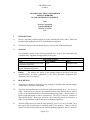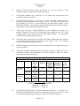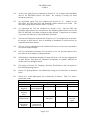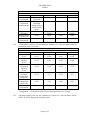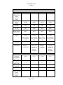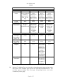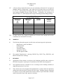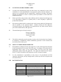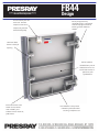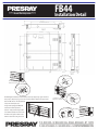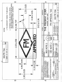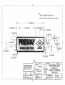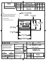
1
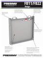
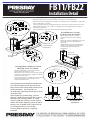
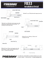
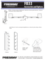
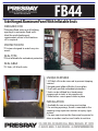
Not to be distributed outside of FM Approvals and its affiliates except by Customer APPROVAL REPORT FB11/FB22, FB33, FB44, AND DOORDAM OPENING BARRIERS FLOOD ABATEMENT EQUIPMENT Prepared for: Presray Corporation 32 Nelson Hill Road Wassaic NY 12592 USA Project: 3040412 Class: 2510 Date of Approval: March 29, 2012 Authorized by: Richard B. Dunne, Manager – Fire Protection Group FM Approvals 1151 Boston-Providence Turnpike PO Box 9102 Norwood, MA 02062 Page 1 of 13 FM APPROVALS 3040412 FB11/FB22, FB33, FB44, AND DOORDAM OPENING BARRIERS FLOOD ABATEMENT EQUIPMENT from Presray Corporation 32 Nelson Hill Road Wassaic NY 12592 USA I INTRODUCTION 1.1 Presray Corporation requested Approval of their Models FB11/FB22, FB33, FB44, and DoorDam opening Barriers for use as flood abatement equipment. 1.2 This Report may be freely reproduced only in its entirety and without modification. 1.3 Standards The applicable portions of the following standards were used for the examination and evaluation of the equipment and applications in this report. Referenced Standard Title Class Number FM Approvals Standard 2510, Flood 2510 Abatement Equipment FM Approvals Standard 5600, Clean 5600 Agent Extinguishing Systems Date December 2006 February 2009 1.4 Listing: The product will appear in the Building Materials Division of the FM Approval Guide, an online publication, in the Flood Abatement Equipment (FM Approvals Class 2510) section. II DESCRIPTION 2.1 These barriers are used to temporarily close openings in building walls when the danger of flood water infiltration is anticipated. 2.2 The FB33 and DoorDam barriers are used for pedestrian openings up to 3 ft (0.91 m) in width. These barriers are placed in pre-installed brackets in the doorway and are secured in place by an expanding jackscrew mechanism and auxiliary clamps. The DoorDam is a lighter weight design that is sold for consumer use. The FB33 is a heavier, commercial and industrial design. Both types of barrier can be manually placed or removed by a single person without the need for any materials handling equipment. 2.3 The FB11/FB22 barriers are used for larger openings, up to 13 ft (3.96 m) in width. They also require the pre-installation of mounting frame in the opening. These are lift-out barriers of sufficient mass that powered materials handling equipment, such as a lift truck Page 2 of 13 FM APPROVALS 3040412 or crane, are required for installation. After insertion in the frame, the barrier is latched into place and its inflatable gasket is pneumatically pressurized to seal against the sides and bottom of the opening. 2.4 The FB44 barrier can also be used for openings up to 13 ft (3.96 m) in width. It also requires the pre-installation of mounting bracket. In addition, it is hinged to one side of the mounting frame and can remain permanently in place, in the open position. When needed, it can be swung shut, latched to the opposite jamb, and sealed by the same type of inflatable gasket as the FB11/FB22 barriers. Powered material handling equipment is only required for the initial installation. When in place, it can be easily moved between the open and closed positions by a single individual. 2.5 All barriers are suitable to prevent water intrusion up to a 3 ft (0.91 m) depth. However, the building wall should be evaluated to verify that it can also withstand the resulting hydrostatic load. 2.6 The attached manufacturer’s brochures provide further information on the configuration of these barriers. III EXAMINATIONS AND TESTS 3.1 All evaluations were to the criteria of the referenced sections of Approval Standard 2510. 3.2 Per Section 4.1.1, Examination, the manufacturer provided sample barriers and components for examination and testing as described for each following evaluation. All test samples were reviewed against the manufacturer’s drawings and specifications and judged to be adequately representative of their designs. 3.2 Per Section 4.1.2, Hydrostatic Test Strength, the entire pressure containing envelope of the inflatable gaskets for the FB11/FB22 and FB44 barriers were tested in an installed FB44 barrier in a 13 ft (3.96) wide opening. The components of the assembly included the seal, the pressure gauge, the valve, and the interconnecting fittings and tubing. Since the maximum rated pressure of this assembly is 30 psi (2.07 bar) the 150 percent required pressure was 45 psi (3.10 bar). This pressure was applied with air and held for 5 minutes with no leakage or other evidence of failure. Subsequent to this test, all components remained intact and functional. 3.3 A System Leakage Test, per Section 4.1.3 was not performed as it was trivial and redundant to the Hydrostatic Test Strength evaluation for this product, since it requires a test pressure of 1.2 times rating, as opposed to the 1.5 times requirement of the latter test. 3.4 A Barrier Membrane Water Leakage test per Section 4.1.4 was not required, since these barriers do not use membranes to prevent leakage. Instead, they use metal structures and perimeter gaskets. 3.5 Component Durability – Cycling was performed per Section 4.1.5. The tested components included the jackscrew assembly for the FB33 and DoorDam and the tank valve for the FB11/FB22 and FB44. These items exhibited no decreased function after 500 cycles of operation. Page 3 of 13 FM APPROVALS 3040412 3.6 Impact and Wear Resistance testing per Section 4.1.6 was not required as these assemblies contain no components relevant to these tests. 3.7 The Abrasion Resistance test of Section 4.1.7 was likewise not required since these assemblies contain no membranes. 3.8 The Vibration Resistance test of Section 4.1.8 was successfully conducted on the component judged vulnerable to failure under vibration. The J-Brace and Compression Clip assembly for the FB 33 and DoorDam and the Ball Knob assembly for the FB11/FB22 and FB44. All components remained fastened during the vibration sequence and exhibited no loss of function subsequent to this test. 3.9 A Salt Spray Corrosion – Residue Build-Up test was conducted per Section 4.1.9. Samples included the J-Brace and Compression Clip assembly for the FB 33 and DoorDam and the Latch Assembly for the FB11/FB22 and FB44. All components remained fully functional after this exposure. 3.10 The J-Brace and Compression Clip assembly for the FB33 and DoorDam were subjected to the Environmental Corrosion Resistance test of Section 4.1.10. This assembly remained fully functional after this exposure. 3.11 The Hail Resistance test of Section 4.1.11 was not required since no membranes are used in these assemblies. 3.12 The Tensile Strength, Ultimate Elongation, and Tensile Set tests of section 4.1.12 were conducted on the two sealing materials used in these assemblies. Table 3.12, below, presents the successful average data. Material FB11/FB22 Seal Skin FB33 & DoorDam Gasket 3.13 Table 3.12 Elastomer Physical Property Tests Exposure Tensile Elongation Percent Stress Percent Original psi Tensile (MPa) Stress None 717 332 N.A. (4.94) 212°F 697 239 97.2 (100°C) (4.81) None 2646 572 N.A. (18.24) 212°F 2273 532 85.9 (100°C) (15.67) Criteria for Success Tensile Strength >/= 500 psi (3.46 MPa) Elongation >/= 100 percent Tensile Set </= 19 percent Percent Original Elongation Tensile Set Percent N.A. 16 71.8 N.A. N.A. 7 93.0 N.A. An Ultraviolet Light and Water Test was conducted per Section 4.1.13. Samples of the FB11/FB22 and FB44 Seal Skin and FB33 and DoorDam Gasket materials were tested. Neither material displayed any cracking or crazing as a result of this exposure. Page 4 of 13 FM APPROVALS 3040412 3.14 An Air Oven Aging Test was conducted per Section 4.1.14. A sample of the Ball Knob used on the FB11/FB22 barriers was tested. No cracking or crazing was noted subsequent to this test. 3.15 An Accelerated Aging Test was conducted per Section 4.1.15. Samples of the FB11/FB22 Seal Skin and FB33 and DoorDam Gasket materials were tested. The successful average data is shown in Table 3.12, above. 3.16 A Compression Set Test was conducted per Section 4.1.16. Only the FB33 and DoorDam gasket material was tested because the inflatable gasket material used for the FB11/22 and FB44 is not under compression when inflated. Compression set averaged 3.2 percent, well under the 15 percent allowable maximum. 3.17 The Extreme Temperature Operation test of Section 4.1.17 was judged to be irrelevant to the designs of these barriers, since no unfolding of membranes or similar actions are required to install these barriers. 3.18 The Cap / Valve Locking/Supervision evaluation of Section 4.1.18 was also considered to be irrelevant to these designs. 3.19 The Tear and Puncture Resistance Test of Section 4.1.19 was also not required, since these barriers do not employ a sealing membrane. 3.20 The Biological / Degradation Resistance Testing of Section 4.1.20 was also inappropriate for these barriers, since their few elastomeric components are synthetic materials not readily sensitive to biological attack. 3.21 The entirety of Section 4.2, Temporary Perimeter Flood Barriers, does not pertain to these building opening barriers. 3.22 Section 4.3, Opening Barriers, was addressed by testing per its subsections, as described below. 3.23 Section 4.3.1, Initial Deployment, was evaluated for all barriers. Table presents the results. Table 3.23 Initial Deployment Evaluation FB11/FB22 FB33 FB44 Person Power 2 person with 1 person 1 person Required power equipment Installation 02:40 02:44 01:06 Duration min:s Foundation Installed Frame Concrete, level Installed Frame Requirements and square Material & Equipment Required Powered lifting equipment & pressurized air None Page 5 of 13 Pressurized air 3.23, below, DoorDam 1 person 01:13 Concrete, level and square None FM APPROVALS 3040412 Evaluation Ease of Construction Special Construction Considerations Application Limitations Damage During Construction Result of Visual Examination Table 3.23 Initial Deployment FB11/FB22 FB33 Easy with lifting Easy equipment Barrier must be None lifted high enough to clear tabs on frame jambs. None Requires flat surface None None Satisfactory Satisfactory FB44 Easy DoorDam Easy None None None None Requires flat surface None Satisfactory Satisfactory 3.24 A Hydrostatic Load Test was performed per Section 4.3.2. The successful results are presented in Table 3.24, below. Table 3.24 Hydrostatic Test Evaluation FB11/FB22 FB33 FB44 DoorDam Water Depth, 3.0 3.0 3.0 3.0 ft (m) (0.91) (0.91) (0.91) (0.91) Width of 13.2 3.0 13.2 3.0 Opening, (4.02) (0.91) (4.02) (0.91) ft (m) Wetted 19.2 9.0 19.2 9.0 Perimeter of (5.85) (2.74) (5.85) (2.74) Opening, ft (m) Maximum 1.54 0.72 1.54 0.72 Allowable (5.83) (2.73 (5.83) (2.73 Leakage Rate, gal/hr (L/h) Measured 0.0 0.0 0.0 0.0 Leakage Rate, (0.0) (0.0) (0.0) (0.0) gal/hr (L/h) Result of Visual Satisfactory Satisfactory Satisfactory Satisfactory( Examination Criterion for Success Leakage Rate </= 0.08 gal/h/ft (0.99 L/h/m) of wetted perimeter over 22 hours. 3.25 A Dynamic Impact Load Test was conducted per Section 4.3.3 with satisfactory results. Table 3.25, below, displays the satisfactory data. Page 6 of 13 FM APPROVALS 3040412 Evaluation Redeployment Prior to First Impact Duration’ min:s Mass of Impact Object, lb (kg) Drop Height, ft (m) Force of Impact, lb (N) Calculated Impact Energy, calorie (J) Location of Impact Repairs Required Result of Visual Examination Maximum Allowable Leakage Rate, gal/hr (L/hr) Measured Leakage Rate, gal/hr (L/hr) Repairs Required Result of Visual Examination Redeployment Prior to Second Impact Duration’ min:s Table 3.25 Dynamic Impact Test FB11/FB22 FB33 02:30 03:30 FB44 01:13 DoorDam 02:26 112 (50.8) 112 (50.8) 112 (50.8) 112 (50.8) 4.0 (1.22) 112 (498) 145 (607) 4.0 (1.22) 112 (498) 145 (607) 4.0 (1.22) 112 (498) 145 (607) 4.0 (1.22) 112 (498) 145 (607) Horizontal Center, approximately 29 in. (74 cm) high None Horizontal Center, approximately 29 in. (74 cm) high None Horizontal Center, approximately 29 in. (74 cm) high None Horizontal Center, approximately 29 in. (74 cm) high None Approximately No visible 1/16 in. (0.2 damage – cm) dent, but acceptable no loss of result function – acceptable result First Repetition of Hydrostatic Test – 1 hour duration 1.54 0.72 1.54 (5.83) (2.73) (5.83) Approximately 1/4 in. (0.6 cm) dent, but no loss of function – acceptable result No visible damage – acceptable result 0.72 (2.73 0.0 (0.0) 0.15 (0.57) 0.0 (0.0) 0.0 (0.0) None None None None Satisfactory Satisfactory Satisfactory Satisfactory 02:07 03:30 01:16 01:07 Page 7 of 13 FM APPROVALS 3040412 Evaluation Location of Impact Repairs Required Result of Visual Examination Maximum Allowable Leakage Rate, gal/hr (L/hr) Measured Leakage Rate, gal/hr (L/hr) Repairs Required Result of Visual Examination 3.26 Table 3.25 Dynamic Impact Test FB11/FB22 FB33 Horizontal as Horizontal as near to Perimeter near to as Possible, Perimeter as approximately Possible, 29 in. (74 cm) approximately high 29 in. (74 cm) high None None FB44 Horizontal as near to Perimeter as Possible, approximately 29 in. (74 cm) high None DoorDam Horizontal as near to Perimeter as Possible, approximately 29 in. (74 cm) high None No visible damage – acceptable result Approximately No visible Approximately 1/4 in. (0.6 damage – 1/2 in. (1.3 cm) dent, but acceptable cm) dent, but no loss of result no loss of function – function – acceptable acceptable result result Second Repetition of Hydrostatic Test – 1 hour duration 1.54 0.72 1.54 0.72 (5.83) (2.73) (5.83) (2.73) 0.0 (0.0) 0.0 (0.0) 0.0 (0.0) 0.0 (0.0) None None None Satisfactory Satisfactory Concrete block wall in which barrier was mounted was damaged and created a leakage point. No repairs were required for the barrier. Zero leakage was achieved in second trial, after repair of wall. Satisfactory Satisfactory Section 4.7, Additional Tests, was invoked to evaluate the pressure gauge used to monitor fill pressure for the inflatable gasket used on the FB11/FB22 and FB44 barriers. Two tests from Approval Standard 5600, Clean Agent Extinguishing Systems, were used to evaluate the pressure gauge. Page 8 of 13 FM APPROVALS 3040412 3.27 A Pressure Gauge Impulse Resistance test was conducted per Section 4.23.2 of Approval Standard 5600 on a sample gauge. After 1000 cycles of pressure from 10 to 50 psi (0.69 to 3.45 bar). Subsequently, the sample gauge was evaluated per Section 4.23.1 of the same Approval Standard, Pressure Gauge Accuracy. Performance was satisfactory, as shown in Table 3.27, which displays the average of ascending and descending readings. Master Gauge Reading, psi (bar) 0 10 20 30 40 50 60 Table 3.27 Pressure Gauge Accuracy Sample Gauge Variance, Reading, percent psi (bar) 0 0 10 0 20 0 30 0 40 0 50 0 60 0 Allowable Variance, percent 12 6 6 4 6 6 15 3.28 No other sections of the Approval Standard were relevant to these designs and no other evaluations were deemed to be necessary. IV MARKING 4.1 The following information appears on the barriers and meets Approval requirements: - Manufacturer’s name and address. Production Date Serial Number Assembly Number Appropriate cautions The FM Approval Mark 4.2 The attached Manufacturer’s drawings DD-FM Tag, DD-LT-Tag, PPR34314, and PRS555 illustrate these markings. V REMARKS 5.1 Applications of these barriers are subject to the limitations specified and are subject to FM Global acceptance of plans prior to installation at FM Global insured properties. 5.2 This equipment has been evaluated for use in resisting riverine flooding conditions at depths not greater than 3 ft (0.9 m) 5.3 These barriers have been designed and manufactured to perform under the hydrostatic and dynamic loads described in Section III of this report. Building structure design and its capacity to accept loads transferred from these barriers require individual evaluation and are beyond the scope of this Approval evaluation. Page 9 of 13 FM APPROVALS 3040412 VI FACILITIES AND PROCEDURES AUDIT 6.1 An audit of the manufacturing facility for these barriers was conducted as a part of this examination to verify implementation of an appropriate quality assurance program. Its purpose was to determine that the manufacturer’s equipment, procedures, and quality program are sufficient to ensure a uniform product representative of that which was examined and tested. 6.2 Follow up facilities and procedures audits (F&PAs) shall be conducted by FM Approvals or its representative program on a quarterly basis, or more frequently if required by jurisdictional authorities. 6.3 FM Approved products shall be produced only at the locations audited by FM Approvals and as specified in the Approval Report. Products bearing the FM Approvals Certification Mark are not permitted to be manufactured at any other location without prior written authorization by FM Approvals. 6.4 The manufacturing site for these barriers is: Presray Corporation 32 Nelson Hill Road Wassaic NY 12592 USA 6.5 The facilities and quality control procedures in place at this location have been found to be satisfactory to manufacture product substantially equivalent to that examined and tested as described in this report. VII MANUFACTURERS RESPONSIBILITIES 7.1 Documentation considered critical to this Approval is on file at FM Approvals and listed in the Documentation File, Section VIII of this report. No changes of any nature shall be implemented unless notice of the proposed change has been given and written authorization obtained from FM Approvals. The Approved Product Revision Report, Form 797, shall be forwarded to FM Approvals as notice of proposed changes. 7.2 It is the manufacturer’s responsibility to keep aware of all jurisdictional and FM Approvals requirements, and any changes thereto, which may affect the acceptance and use of these barriers VIII DOCUMENTATION Document Number 98407A132 Anchor Ref DD-FM Tag DD-LT-Tag FB11-FB22 FS Critical Documents Description E-Style Zinc and Yellow ChromatePlated Steel External Retaining Ring Anchor Reference FM Approval Tag DoorDam Liability Tag FB11-FB22 Fact Sheet Page 10 of 13 Revision 03/26/ 2010 - FM APPROVALS 3040412 Document Number FB11-FB22 SS FB22-XXXXX-01 FB33 FB33 FS FB33 SS FB33-XXXXX-03 FB44 FS FB44 SS FB44-XXXXX-02 IM FB22 IMFB44 PPR34314 PR18571 PR19685 PR22718 PR24496 PR24497 PR24648 PR28434 PR30367 PR31206 PR31352 PR31709 PR31911 PR31912 PR31913 PR32524 PR32637 PR32754 PRS535 PRS555 PRS582 PRS857 PRV4873.003 Critical Documents Description FB11-FB22 Specification Sheet FB 22 Flood Barrier Installation, Operation, and Maintenance Manual for FB33 Flood Barrier FB33 Fact Sheet FB33 Specification Sheet FB33 FB44 Fact Sheet FB44 Specification Sheet FB44 Flood Door Installation, Operation, and Maintenance Manual for FB 2 Flood Barrier Installation, Operation, and Maintenance Manual for FB44 Flood Barrier Presray / FM Approval Name Plate Manifold Stud FB 22 Corner Cove for 3/8 in. Jamb Stock Locking Bolt 1 in. Diameter Latch Body 1 in. Diameter Plexiglass Guard Adhaco Hinge H-418 Assembly Layout Retainer Extrusion for PR18569 Wheel Assembly FB11 & FB22 Handle FB33 Handle Linkage Arm Right Hand Jack Nut Left Hand Jack Nut DoorDam XL Mounting Angle Compression Clip Jamb Clip Inflatable Seal Nameplate Inflatable Seals Retainer Plate for PRS582, 535 Valve Fitting (1/8-27NPT Female) Revision B A A A A B A A A C D C W B E B C Note: The characters “XXXXX” in some document numbers indicate the customer work order number, which is unique to each customer. IX CONCLUSION The Presray Corporation Models FB11/FB22, FB33, FB44, and DoorDam opening Barriers meet FM Approvals requirements for use as flood abatement equipment. Since a Page 11 of 13 FM APPROVALS 3040412 duly signed Master Agreement is on file for this manufacturer, Approval is effective the date of this report. EXAMINATION BY: Armand V. Brandao TESTING BY: Presray Corporation personnel and FM Approvals personnel Armand Brandao, Kalyn Magazu, and John Normington. PROJECT DATA RECORD: Project 3040412 ATTACHMENTS: Appendix 1 - Product Listing Manufacturer’s Brochures FB11/FB22, FB33, FB44, & DoorDam Manufacturer’s Drawings DD-FM Tag, DD-LT-TAG, PPR34314 & PRS555. REPORT BY: REPORT REVIEWED BY: Armand V. Brandao, P.E. Senior Engineering Specialist Fire Protection Group Brian K. MacDonald Technical Team Manager Fire Protection Group Page 12 of 13 FM APPROVALS 3040412 Appendix 1 Approval Guide Listing The following opening barriers provide protection against riverine flooding up to depths of 3 ft (0.9 m). DoorDam Removable Flood Panel with compression gasket. For openings up to 3 ft (0.9 m) in width. Expandable by hand crank to fit multiple openings over a 4 in. (100 mm) range. Can be installed in three different configurations. A Style 1 installation uses J-Braces and CompressionClips on otherwise unmodified building openings with a recess on the water side of the opening a minimum of 1 in. (25 mm) wide and with a minimum of 2 in. (50 mm ) deep on either side of opening. A Style 2 installation uses a Z profile jamb bracket on either side of the opening to reinforce the corners of the opening and to create the recess wherein the panel is installed. A Style 3 installation also uses the Z brackets, but mounts them on the face of the wall outside the opening, requiring a minimum of 1 in. (25 mm) of wall on either side of the opening to support the panel. All three styles use the J-Braces and Compression-Clips to compress the gasket against the bottom of the opening. FB33 Removable Flood Panel with compression gasket. For openings up to 3 ft (0.9 m) in width. Expandable by hand crank to fit multiple openings over a 4 in. (100 mm) range. The FB33 is similar to the DoorDam, but offers a heavier construction. Requires pre-installation of jamb brackets either inside of the opening or on the water side of the wall, with a minimum of 1 in. (25 mm) overlap of the wall on either side of the opening. A variety of bracket arrangements are available. J-Braces and Compression-Clips are used to compress the gasket against the bottom of the opening FB11/FB22 Aluminum Lift-Out Panel with inflatable seals. For openings up to 13 ft (3.96 m) width. Requires pre-installation of frame, either inside of the opening or on the water side wall face. Requires a pressurized gas supply to inflate seal. Must be removed and stored to return opening to service. FB44 Side-Hinged Aluminum Panel with inflatable seals. For openings up to 13 ft (3.96 m) width. Requires pre-installation of frame, either inside of the opening or on the exterior wall face. Requires a pressurized gas supply to inflate seal. Designed for permanent installation. Can be closed by a single operator when required. Allows unobstructed use of opening when in open position. Page 13 of 13 www.Presray.com FB11/FB22 Aluminum Lift-Out Panel With Inflatable Seals DESIGNED FOR Openings of any size Doorways, loading docks, any municipal, industrial or commercial opening PROTECTION TO Custom designed to match any size needs up to 40 square feet. SEAL TYPE Dual inflatable for redundant protection SEAL AREA 3 Sides, sill, left & right jambs UNIQUE FEATURES Sill can be recessed to prevent tripping hazard Lightweight, panels up to 18 sq ft can typically be handled by one or two people, larger panels can be installed with fork-lift or other device Dual seals provide redundant protection Seals can be inflated by a hand pump, compressed air tank, or air compressor INSTALLATION Available for new or existing construction Frame can be jamb mounted (in between the door frame), or face mounted (outside the door frame, attached to the building) For existing openings, frame is mounted to the opening using expansion anchors. For new construction the frame can be cast in place or bolted in similar to existing opening description FB11/FB22 Design www.Presray.com Air connection ports for Slide latches lock barrier securely in Handles allow for easy dual seals. Fill with handling with a forklift or compressed air from (for barriers less than 18 compressor, portable sq ft) one or two people tank or hand pump opening Dual inflatable seals provide redundant protection while ensuring a complete seal Panel is 6061-T6 aluminum for years of Conversion frame is low carbon steel maintenance free use. (stainless steel available), and Can be left natural, or available as a jamb mount (mounts in painted to your between the left & right jambs), face specifications mount (as shown), or cast in place for new construction FB11/FB22 Installation Detail www.Presray.com Installation Using Adhesive Inserts Use barrier frame to mark location of holes on existing wall. Remove frame & drill hole in wall according to the installation manual. Insert adhesive capsule. Using setting tool provided by Presray, drive the anchor into the hole. After adhesive has set, remove setting tool and apply RTV sealant to mounting surfaces Attach the frame to the wall with hardware provided. R T V S E AL AN T Installation Using Expansion Anchors Use barrier frame to mark location of holes on existing wall. Remove frame & drill hole in wall according to the installation manual. Apply RTV sealant to mounting surfaces and attach the frame to the wall with hardware provided. R T V S E AL AN T J amb Mount In Opening Face Mount To Wall Cast In Place Jamb R T V S E AL AN T Installation When Frame Will Be Cast In Place Barrier subframe is placed into the form of the wall to be cast. After the concrete has cured, the form is removed leaving the subframe flush with the new wall. The barrier is now ready to be attached to the subframe according to the instruction manual. If the opening that the panel will protect has not been poured yet, the frame for the panel can be integrated with the wall during the pour. This provides an aesthetically appealing frame that is flush with the jamb. If the opening is preexisting, you can choose a jamb mount frame that mounts between the existing jambs, or a face mount jamb that mounts on the wall to either side of the opening. Both of these designs are available with a recessed sill (as an option) that is cut into the existing floor to prevent a tripping hazzard. CONCRETE WELDED TO ANCH ORS SUBF RAME SUBF RAME OF B ARRIE R TO B E CAS T IN P LACE FORM CAST CON CRET E WA LL & FAC E OF SUBF RAME ARE FLUS H Standard Sill Recessed Sill (Optional) www.Presray.com FB33 Removable Flood Panel With Compression Gasket DESIGNED FOR Entry doors, garage doors, openings requiring rapid, easy to install protection where low leakage is acceptable. PROTECTION TO The width is custom designed to match any protection size needs, while the height is 36” SEAL TYPE Neoprene outer envelope Combination compression/lip seal around perimeter SEAL AREA 3 sides - floor and both sides UNIQUE FEATURES Patented hand-crank expandable steel frame to fit multiple openings Economical and easy to use and handle. Drop in place and deploys securely in opening in approx. 5 minutes by one person. INSTALLATION Available for new or existing construction Optional jamb and sill frame are often required to hold back hydrostatic load At the first sign of a flood, simply insert the panel into the opening and expand it by turning the handle until the seals are compressed FB33 Design www.Presray.com Turn carrying handle to expand the barrier Patented steal scissor jack frame Reinforced corners Durable Neoprene envelope protected by aircraft aluminum Debris Shield www.Presray.com FB33 Installation Detail Method 1 uses Z-Bracket and compression clip Method 2 uses Z-Bracket and compression clip mounted on building face with at least 1” of building to take water load. Method 3 uses L-Bracket, J-Brace and compression clip Method 4 uses J-Brace and compression clip when there is a door or other frame with at least 1” to take the water load. FB33 Accessories and Options www.Presray.com Mullion—Used to connect multiple panels. Made from aviation-grade aluminum. Anchored to concrete or other suitable surface. Panels Mullion Mullion Jamb Channels- Used in unseating load applications or where the jamb sealing surface is rough. J-brace—used alone or with L-Bracket Z-Bracket L-Bracket Compression clipused with Z-Bracket and J-Brace to provide downward force where FB33 meets the wall www.Presray.com FB44 Side Hinged Aluminum Panel With Inflatable Seals DESIGNED FOR Keeping flood water out of building openings or perimeter flood walls. Ideal for quick deployment requirements where a flush bottom sill is required. PROTECTION TO Custom designed to match any size needs. SEAL TYPE Dual inflatable for redundant protection SEAL AREA 3 Sides, sill & both sides UNIQUE FEATURES 3/8”thick sill can be recessed to prevent tripping hazzard Hinged panel glides effortlessly into place Dual seals provide redundant protection Seals can be inflated by a hand pump, compressed air tank, or air compressor Slide latches secure panel when in place INSTALLATION Available for new or existing construction For existing openings, frame is mounted to the opening using expansion anchors or epoxy type anchors For new construction the frame can be poured in place or anchors can be used similar to existing opening www.Presray.com Air connection ports for dual seals. Fill with compressed air from compressor, portable tank or hand pump FB44 Design Presray designed 6 way adjustable hinge. Low friction with oil impregnated bronze bushing provide effortless motion Slide latch locks barrier securely in opening Panel is 6061-T6 aluminum for years of maintenance free use. Can be left natural, or painted to your specifications Conversion frame is low carbon steel (stainless steel available), and available in face mount or, jamb mount Dual inflatable seals provide redundant protection while ensuring a complete seal www.Presray.com FB44 Installation Detail Existing concrete wall Jamb of barrier Installation Using Adhesive Inserts RTV sealant Existing concrete Expansion anchor Adhesive capsule Adhesive insert Frame of barrier RTV sealant Hex head screw Setting tool Flat washer Expansion anchor The FB44 Hinged Flood Barrier provides maximum protection by simply closing a gate! The barrier is always in place, always ready to go! In the event of a flood condition, simply close the gate, lock the latch and inflate the seals. The dual redundant seals provide excellent protection. For large width openings, dual FB44’s with attached center mullion provide fast protection. Simply close the first gate (with center mullion attached) and seal and secure the mullion to the ground. After the center mullion is secured the second gate is closed and latched. Then inflate the seals. That’s it, FB 44 Double Gate With Attached Center Mullion your opening is secure! Sill of barrier Installation Using Expansion Anchors RTV sealant Existing concrete floor Subframe of barrier to be cast in place Concrete anchors welded to subframe Form Cast concrete wall & face of subframe are flush Installation When Cast In Place 6.00 1.38 This product is intended to be used for the purpose and under the conditions stated by DoorDam/Presray in its product literature. In purchasing this product from Presray, you agree to assume all risks related to and/or arising from your ownership, installation and use of the product. Presray shall not be help liable for any improper or incorrect, ownership, installation or use of this product and assumes no responsibility for anyone's ownership, installation or use of the product. To read Presray's full disclaimer and to learn about the proper and intended use of this product, please consult the proper literature and/or our website, www.DoorDam.com Be sure to place the product into the openings as indicated in the User Manual. (-----TEXT-----) REV TEXT 24"-28"(DDA18X24) 28"-32"(DDA18X28) 31"-35"(DDA18X31) 34"-38"(DDA18X34) 37"-41"(DDA18X37) 40"-44"(DDA18X40) 43"-47"(DDA18X43) 46"-50"(DDA18X50) 24"-28"(DDA26X24) 28"-32"(DDA26X28) 31"-35"(DDA26X31) 34"-38"(DDA26X34) 37"-41"(DDA26X37) 40"-44"(DDA26X40) 43"-47"(DDA26X43) 46"-50"(DDA26X50) 25"-29"(DDS36X25) 28"-32"(DDS36X28) 31"-35"(DDS36X31) 34"-38"(DDS34X34) 37"-41"(DDS36X37) 40"-44"(DDS36X40) 43"-47"(DDS36X43) 46"-50"(DDS36X50) -3 "THIS DESIGN IS THE PROPERTY OF THE PRESRAY CORPORATION AND IS SUBMITTED IN CONFIDENCE. ALL RIGHTS RESERVED. COPYING OR IMITATION EXPRESSLY PROHIBITED. ALL OR PORTIONS OF THIS DESIGN MAY BE SUBJECT TO PROPRIETARY RIGHTS" DRAWING NOT RELEASED UNTIL DATED AND APP'D. BELOW. 3/22/2012 DATE RL APVD. BREAK ALL SHARP CORNERS 1/32 DO NOT SCALE DRAWING c PRESRAY CORP. -2 -1 DETAIL STOCK SIZE/PART NO. MATERIAL QA PLAS DD-LT-TAG PART NUMBER DD-LT-18X24 DD-LT-18X28 DD-LT-18X31 DD-LT-18X34 DD-LT-18X37 DD-LT-18X40 DD-LT-18X43 DD-LT-18X46 DD-LT-26X24 DD-LT-26X28 DD-LT-26X31 DD-LT-26X34 DD-LT-26X37 DD-LT-26X40 DD-LT-26X43 DD-LT-26X46 DD-LT-36X25 DD-LT-36X28 DD-LT-36X31 DD-LT-36X34 DD-LT-36X37 DD-LT-36X40 DD-LT-36X43 DD-LT-36X46 - KEY: TEXT = "BARRIER SIZE"(MODEL NUMBER) QC REVIEW OK PAINT/FINISH TOLERANCE UNLESS NOTED FRACTIONS 3 DECIMAL PLACES 2 DECIMAL PLACES ANGLES 1/32 .010 .030 2 SCALE 2:1 & NOTED DESCRIPTION THE PRESRAY CORP. WASSAIC, NEW YORK NAME DOORDAM LIABILITY TAG DR. 3/22/2012 WF CHK. 3/22/2012 RL APVD. 3/22/2012 RL DD-LT-TAG SHEET 1 OF 1 REV 2 1 B PRS555 REV SHEET 1 1 OF DATE REV DESCRIPTION DR CHK APVD QA 7/ 18/ 69 A REVISE & REDRAWN ERC 8/ 12/ 09 B CHG ADDRESS, WAS EH WF WF CO PAWLING DRILL 1/ 16 DIA THRU 4 HOLES 0.13 NOTES: 1.-SIZES AND POSITIONS OF RECTANGULAR BLOCKS ARE TO BE SCALED FROM DOUBLE SIZE DRAWING; LETTERING SIZES SHOULD BE PROPORTIONATE TO THE REMAINING SPACE. B B 0.06 2. BACKGROUND TO BE BLUE. 3.-LETTERING, BORDER AND BLOCKS TO BE ALUM. PRESRAY WASSAIC, NEW YORK SERIAL DATE 1.19 ASSEMBLY NO. .035 THICK 0.13 QTY A -2 -1 DETAIL SHT RRG APVD. BREAK ALL SHARP CORNERS 1/32 DO NOT SCALE DRAWING 2.75 0.06 3.00 0.06 MATERIAL STOCK SI ZE/ PART NO. DRAWI NG NOT RELEASED UNTIL DATED AND APP'D. BELOW. DATE c PRESRAY CORP. 2 0.06 0.06 "THIS DESIGN IS THE PROPERTY OF THE PRESRAY CORPORATION AND IS SUBMITTED IN CONFIDENCE. ALL RI GHTS RESERVED. COPYING OR IMI TATION EXPRESSLY PROHI BITED. ALL OR PORTIONS OF THIS DESIGN MAY BE SUBJECT TO PROPRIETARY RIGHTS" 7/ 18/ 69 1.44 0.06 MATERIAL QA 0.35 THK ALUM PAINT/ FINISH BACKGROUND BLUE SILVER (ALUM LETTERS) TOLERANCE UNLESS NOTED FRACTIONS 3 DECIMAL PLACES 2 DECIMAL PLACES ANGLES 1/ 32 .010 .030 2 QC REVIEW OK SCALE 1/ 1 DESCRI PTION THE PRESRAY CORP. A WASSAIC, NEW YORK NAME NAMEPLATE DR. CHK. & NOTED APVD. 7/18/ 69 JEA 7/ 18/ 69 RE B PRS555 7/ 18/69 GC SHEET 1 1 REV OF 1