1
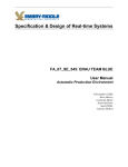
User Manual
The first step to automation
Version 1 – (C)opyright 1999-2002 IRAI
AUTOMGEN is a registered trademark of IRAI.
This trademark may not be used without the prior agreement of
IRAI.
Introduction
The AUTOMGEN Starter Kit allows you to discover the world of
automation. As you will have already noticed automation is
everywhere in our daily life. This fascinating technology allows
you to make your most ambitious projects come to life in an
entertaining way.
Let's get started straight away.....
Installing the program
The AUTOMGEN Starter Kit program requires a PC compatible
computer with the following specification :
WINDOWS 95, 98, ME, NT4, 2000 or XP operating system,
at least 16MB of memory,
at least 30MB of free space available on the hard drive,
a video card with a resolution of at least 800 x 600 pixels in
65535 colour mode,
- a CD-ROM drive,
- a mouse.
-
Start up your computer and place the AUTOMGEN Starter Kit
CD-ROM in the CD-ROM drive.
The installation program is normally launched automatically. If
this does not occur, click on the Windows "Start" button, select
"Run", then use the "Browse" button to select the file
"Setup.exe" from the root directory of the CD-ROM.
Answer the questions displayed by the installation program....
AUTOMGEN Starter Kit - Version 1.03
1
The demonstration copy
The AUTOMGEN Starter Kit demonstration copy is supplied for
evaluation purposes only. This version of the program does not
allow the applications developed to be saved. It can be
upgraded to the full version of the product by inputting a
registration number which will supplied when your order is
processed.
The technical and commercial teams at IRAI would like to thank
you for the interest which you have shown in their products.
Contacting IRAI
For all technical questions and comments please contact us by:
Telephone :
(33) 4 66 54 91 30
Fax :
(33) 4 66 54 91 33
E-mail :
[email protected]
You can also obtain further product information from our
Internet site :
http://www.irai.com
AUTOMGEN Starter Kit - Version 1.03
2
Getting started with the
AUTOMGEN Starter Kit
From the Windows "Start" menu choose the "Programs" option,
then "AUTOMGEN Starter Kit".
From the list of options1 choose " Simulation ".
This mode allows the program to be used without a model or
interface.
Next click on the "Start" button …
1
Depending on the version of AUTOMGEN STARTER KIT the list of options may be limited to one
type of operational model.
AUTOMGEN Starter Kit - Version 1.03
3
Click on the "Open" button on the tool bar at the top of the
screen. Open the file called "Example" in the sub-directory
"example\general" of the directory where the AUTOMGEN
Starter Kit has been installed (the default installation directory is
C:\Program Files\IRAI\Ask).
Ckick here
AUTOMGEN Starter Kit - Version 1.03
4
Click on the "Run" button.
Click here
AUTOMGEN Starter Kit - Version 1.03
5
Click in this area …
Comment : clicking on the switches with the left button of the
mouse changes their setting (bistable), the right button returns
them to their default setting (monostable).
This ends our quick introduction to the AUTOMGEN Starter Kit
program.
We will leave you to explore the other examples.
The rest of the manual shows you how to use the ASK
development environment and simplified graphical automation
language to construct the steps in your automation programs...
AUTOMGEN Starter Kit - Version 1.03
6
The ASK environment
Choice of option
As we have discovered in the previous chapter that an option
must be chosen when opening the program. This choice
determines the elements available to create a program and the
way in which it will be run (control or simulation of a particular
interface, simulation, etc ...).
Ticking the box "Please do not show this dialog box on start up"
allows the option displayed by AUTOMGEN STATER KIT on
start up to be set. When the program is restarted it will display
the option which was last used without offering a choice to the
user.
To display the selection dialog box again press the [SHIFT] key
on the keyboard while AUTOMGEN STARTER KIT is starting
up.
Choosing the display mode
The radio buttons "professional environment" and "standard
environment" allow the user to choose between two styles of
environment according to their preference.
Registering the program
A licence number will be supplied when you decide to purchase
the AUTOMGEN STARTER KIT. This licence number is your
unique personal number and must not be communicated to
anyone else. The "LICENCE" button allows you to input the
licence number and convert the demonstration copy into a full
version of the program.
AUTOMGEN Starter Kit - Version 1.03
7
Creating programs
Designing a program
The creation of programs can be carried out entirely by using
the mouse. In principal a program is created by dragging
elements (blocks) from the tool bar on the right or left of the
screen and placing them on the work sheet.
Work sheet
Tool bar
Modifying the settings for a block
Certain blocks may be set to behave in several possible ways,
these are referred to as configurable blocks, for example a
timing block may cause a long or short delay.
AUTOMGEN Starter Kit - Version 1.03
8
The configurable blocks can be recognised by a data box. The
box contents are green characters on a black background.
To modify the setting of the block place the mouse cursor over
the data box. The settings will then be visible.
If a data box contains a numerical value buttons marked "+" and
"-" will appear below it. By clicking on the buttons the value can
be changed. The value can also be modified directly by clicking
on the field and typing in the new value using the keyboard.
Moving the mouse cursor outside the field saves the new value.
If the data box does not contain a numerical value then a menu
will appear. In this case the setting is modified by choosing an
item from the menu with the mouse.
Moving a block
To move the position of a block on the work sheet, place the
cursor over the block, hold down the left mouse button and
move the cursor to the new position. Releasing the mouse
button places the block in the new position.
Deleting a block
Click on a block with the right mouse button and choose
"Delete" from the menu displayed.
Selecting one or more
Click on a block to select it or deselect it (this acts as a
selection switch). Black crosses appear at the four corners of
the selected block. If the [SHIFT] key is held down more than
one block can be selected by clicking on each block in turn.
Another method for selecting a group of blocks is to click on the
empty area of the work sheet and keep the left button of the
AUTOMGEN Starter Kit - Version 1.03
9
mouse depressed. Moving the cursor with the button held down
will draw a line. Releasing the mouse button will select all the
blocks which are fully or partially in the area defined by the line.
The blocks marked in this way may be moved or deleted by
using the same method as for a single block.
AUTOMGEN Starter Kit - Version 1.03
10
The ASK simplified
graphical automation
language
This language draws its inspiration from GRAFCET which is
currently the reference standard in the world of automation.
The ASK language is made up of two groups of elements :
actions and tests.
The language is based on the concept of "state". For a state
there is a corresponding action. The change from one state to
another is conditional on a test.
Consider the example of a train described in everyday
language...
The train is at a standstill
Until the driver moves the lever to advance the train.
The train advances
Until the driver moves the lever to stop the train.
And so on …
If these lines appear logical to you then you will have no
problems using the ASK language...
AUTOMGEN Starter Kit - Version 1.03
11
The essential rules in the ASK language are :
- an action can only be followed by a test or nothing,
- a test can only be followed by an action or nothing.
The graphical elements in the ASK language
♦ Actions are displayed in blue.
♦ Tests are displayed in green.
♦ Links are represented by arrows.
Here is an example of a program :
An action
A test
An action
A test
A link
AUTOMGEN Starter Kit - Version 1.03
12
Actions
• A line of action starts with either an
block (if the action must take place at the start of
the program) or an
block (otherwise).
• To the right of these blocks there will be :
- Nothing if nothing has to happen,
block if the action must take place while the
- a
state is active and stop when it is exited,
- an
if the action must be activated in this state
(it will continue even after exiting the state),
block if the action must be deactivated (this
- a
stops an action started by the "Activate..." block.
• To the right of these blocks there is a block defining the
action to be performed :
AUTOMGEN Starter Kit - Version 1.03
13
block to activate a general type of output
- a
variable. Special blocks are also available depending on the
option.
- a
block to introduce a time factor (see later).
or
- a
variable (see later).
block to process a numeric
If several actions are to be performed further blocks can be
placed to the right (the last two steps described above). For
example :
Tests
• A test line starts with the block.
• To the right of this block there is :
- nothing if the test is always true (in this case the program
always passes on to the next action),
AUTOMGEN Starter Kit - Version 1.03
14
- one or more blocks making up the condition :
- the
block to perform a general test on an input
variable, special blocks are also available depending on
the option.
- the
later).
block tests for the end of a time delay (see
- the
and
variable (see later).
,
- the
and
blocks test a numeric
,
,
,
blocks allow equations to be
defined.
For example :
AUTOMGEN Starter Kit - Version 1.03
15
tests input 0, input 1 and not input 2.
block tests the presence (automation
The
specialists talk about a "firing condition" or "triggering
condition") of an item of data.
Links
The links which simply allow an action to be linked to a test
(which is useful for looping a program such as our previous
example).
Parallel processes
The ASK language may be used to define several tasks which
must be performed at the same time. To do this it is sufficient to
draw several paths on the program work sheet.
Example :
Choices
and
The
follow two different paths.
blocks allow the program to
AUTOMGEN Starter Kit - Version 1.03
16
block must be written below an action, the two
The
branches created must lead to two tests.
block allows two branches to be combined into a
The
single one. The two branches must come from two tests. The
branch below must lead to an action.
Example :
The other language elements
Temporisation
Temporisations are the language elements which allow time
delays to be defined. A temporisation is identified by a number
from 0 to 200 and possesses a duration between 0 and 65535
expressed in tenths of a second.
AUTOMGEN Starter Kit - Version 1.03
17
A temporisation is started by an action. The end of the
temporisation is tested by a test.
It is only possible to use each temporisation number once in
each program.
Below is an example of a program using temporisation.
When the program is run, temporisation 0 is started with a
duration of 2 seconds, when the temporisation ends the
program continues.
Conditional Actions
block allows a condition to be added to an
The
action. One or more condition blocks must be placed to the right
of this block.
The
block easily allows a response to a warning. It
must be placed to the right of a
AUTOMGEN Starter Kit - Version 1.03
block.
18
Example :
Working with numeric variables
The ASK language allows the use of numeric variables called
"words". The numeric variables are identified by the letter "W"
followed by a number from 200 to 4999 (the words 0 to 199 are
reserved).
The words are 16 bit encoded signed numeric variables.
Two action blocks allow a constant to be placed in a word or a
calculation to be performed between two words and the result
placed in a third word.
Two test blocks allow the comparison of a numeric variable with
a constant or another word.
AUTOMGEN Starter Kit - Version 1.03
19
Example : count four pushes on a push button connected to
input 0 before activating output 0.
AUTOMGEN Starter Kit - Version 1.03
20
Creating our first program
Our objectives are as follows :
- We are going to use the "Simulation" option,
- Pushing the push button connected to input 3 will light up the
warning light connected to output 4 for 5 seconds,
- If the button is pressed again, the warning light lights up again
for 5 seconds and so on...
AUTOMGEN Starter Kit - Version 1.03
21
AUTOMGEN Starter Kit - Version 1.03
22
AUTOMGEN Starter Kit - Version 1.03
23
AUTOMGEN Starter Kit - Version 1.03
24
AUTOMGEN Starter Kit - Version 1.03
25
AUTOMGEN Starter Kit - Version 1.03
26
AUTOMGEN Starter Kit - Version 1.03
27
Comment : by clicking with the right mouse button on switch 3 it
behaves as a monostable push button.
AUTOMGEN Starter Kit - Version 1.03
28
Appendix
Options, input and output interfaces
AUTOMGEN Starter Kit - Version 1.03
The POLYFUNCTION
operating section from
POLYDIS.
® The POLYFONCTION name is a registered trademark. © POLYDIS. Used with the kind permission of POLYDIS
To use this option you must connect an RPX I/O input/output
module configured as slave number 1. The cabling to the RPX
I/O interface of the sensors and activators must conform to that
described in the technical documentation supplied by
POLYDIS.
AUTOMGEN Starter Kit - Version 1.03
®
The FISCHERTECHNIK
model elevator
® The name FISCHERTECHNIK is a registered trademark. © FISCHERTECHNIK. Used with the kind permission of FINAL.
To use this option you must connect the FISCHERTECHNIK® interface to the parallel port on
the PC. The cabling of the sensors and activators is as follows:
OUTPUT :
Raise elevator
Lower elevator
Green warning light
Orange warning light
Red warning light
O0
O1
O2
O3
O4
INPUTS
Call the elevator to the ground floor
Call the elevator to level 1
Call the elevator to level 2
Elevator present at level 0
Elevator present at level 1
Elevator present at level 2
I0
I1
I2
I3
I4
I5
AUTOMGEN Starter Kit - Version 1.03
®
The LEGO model
Cream Machine”
“Ice
® The names LEGO, LEGO Dacta are registered trademarks. © Groupe LEGO. Used with the kind permission of LEGO Dacta France
To use this option you must use the following cabling :
Rotary
sensor
Blue
ice
cream
dispenser
Rotary
sensor
yellow
ice cream
dispenser
Push
button
Blue
light
Yellow
light
Green
light
Buzzer
Yellow ice
cream
distributor
motor
Blue icecream
distributor
motor
Optical
sensor
portion
detection
AUTOMGEN Starter Kit - Version 1.03
®
The driver for the LEGO
interface
® The names LEGO, LEGO Dacta are registered trademarks. © Groupe LEGO. With the kind permission of LEGO Dacta France
Settings
The driver automatically configures itself. The interface can be
connected to COM 1 or COM 2, it is detected automatically on
running the automation application.
Connection
The connection between the computer and the LEGO® interface
must be made using the serial connecting cable supplied by
LEGO®.
Communication with inputs / outputs
The following variables communicate with the interface :
Inputs I0 to I7 : the 8 Boolean states of the interface inputs.
Outputs O0 to O15 : the 16 Boolean interface outputs :
O0 = position 1 of output A,
O1 = position 2 of output A,
O2 = position 1 of output B,
O3 = position 2 of output B,
O4 = position 1 of output C,
O5 = position 2 of output C,
O6 = position 1 of output D,
O7 = position 2 of output D,
O8 = position 1 of output E,
O9 = position 2 of output E,
O10 = position 1 of output F,
AUTOMGEN Starter Kit - Version 1.03
O11 = position 2 of output F,
O12 = position 1 of output G,
O13 = position 2 of output G,
O14 = position 1 of output H,
O15 = position 2 of output H.
Comment : if positions 1 and 2 of an output are driven at the
same time, then the output is not driven in either position.
Words W200 to W207 : the 8 analogue inputs for the
temperature sensor and optical sensor.
Words W208 to W215 : the 8 digital inputs for the angular
position sensor.
Input I8 gives the operational state of the interface : I8=1 if the
interface is connected and the operation is correct, I8=0 if the
interface is disconnected or the STOP button is pushed down.
AUTOMGEN Starter Kit - Version 1.03
®
The driver for the RPX I/O
interface
® The name RPX I/O is a registered trademark. © CROUZET AUTOMATISME
Settings
The driver is automatically configured. The interface can be
connected to COM1 or COM2, it is detected automatically on
running the application. Only one module can be connected.
The module must be configured to address 1 : switches i0 to i4
to 0, switch i5 to 1. The parity must be set to "no parity" : switch
i6 to 0. The speed is automatically detected and may be
adjusted to one of the possible values, 38400 baud (i8 to 1 and
i9 to 1), 19200 baud (i8 to 0 and i9 to 1), 9600 baud (i8 to 1 and
i9 to 0) or 4800 baud (i8 to 1 and i9 to 1).
The RPX I/O interface watchdog is activated automatically. The
outputs default to state 0 if there is a break in communication.
Connection
The connection between the RPX I/O interface and the
computer must be made using an RS232/RS485 converter (see
CROUZET documentation).
Communication with inputs/outputs
Only the Boolean inputs and outputs are usable.
16 I inputs and 16 O outputs are reserved for each RPX I/O
interface module
The following variables communicate with the interface :
I0
I1
I2
I000
I001
I002
O0 O000
O1 O001
O2 O002
AUTOMGEN Starter Kit - Version 1.03
Etc …
I16 I100
I17 I101
Etc …
Etc …
O16 O100
O17 O101
Etc…
Input I128 gives the operational state of the interface. I128=1 if
the interface is connected. I128=0 if the interface is
disconnected.
AUTOMGEN Starter Kit - Version 1.03
®
The driver for the PILOTIX
interface
® The name PILOTIX is a registered trademark © LOGEDIC Groupe CHRYSIS Used with the kind permission of LOGEDIC Groupe CHRYSIS.
Settings
The driver is configured to control the PILOTEX® interface
through the LPT1 parallel port.
Connection
The connection between the PILOTIX® interface and the
computer must be made using a parallel connecting cable.
Communication with inputs/outputs
The following variables communicate with the interface :
Inputs I0 to I7 : the 8 Boolean states of the interface inputs.
Outputs O0 to O8 : the 8 Boolean states of the interface
outputs.
AUTOMGEN Starter Kit - Version 1.03
The driver for the
®
FISCHERTECHNIK
interface
® The name FISCHERTECHNIK is a registered trademark. © FISCHER With the kind permission of FINAL.
Settings
The driver is configured automatically. The interface can be
connected to LPT1, LPT2, LPT3 or LPT4. It is automatically
detected on running the automation application. Two modules
can be connected.
Connection
The connection between the FISCHERTECHNIK interface and
the computer must be made using the parallel connection cable
supplied by FISCHERTECHNIK.
Communication with inputs/outputs
The following variables communicate with the interface :
Inputs I0 to I15 : the 16 Boolean states of the interface inputs.
Outputs O0 to O15 : the 16 Boolean interface outputs :
O0 = position 1 of output W1,
O1 = position 2 of output W1,
O2 = position 1 of output W2,
O3 = position 2 of output W2,
O4 = position 1 of output W3,
O5 = position 2 of output W3,
O6 = position 1 of output W4,
O7 = position 2 of output W4,
O8 = position 1 of output W5,
AUTOMGEN Starter Kit - Version 1.03
O9 = position 2 of output W5,
O10 = position 1 of output W6,
O11 = position 2 of output W6,
O12 = position 1 of output W7,
O13 = position 2 of output W7,
O14 = position 1 of output W8,
O15 = position 2 of output W8.
Words W200 to W201 : the 2 analogue inputs.
Input I16 gives the operational state of the interface : I16=1 if
the interface is connected and operating correctly, I16=0 if the
interface is disconnected.
AUTOMGEN Starter Kit - Version 1.03
The driver for the ATECH
interface
Settings
The driver is configured automatically.
Connection
The connection between the ATECH interface and the
computer must be made with a parallel cable.
Communication with inputs / outputs
The following variables communicate with the interface:
Inputs I0 to I11 : the 12 Boolean interface inputs.
Outputs O0 to O7 : the 8 Boolean interface outputs :
AUTOMGEN Starter Kit - Version 1.03
®
The driver for the LEGO
9771 interface
® The names LEGO, LEGO Dacta are registered trademarks. © Groupe LEGO. Used with the kind permission of LEGO Dacta France
Settings
The driver is configured automatically.
Connection
The connection between the LEGO® 9771 interface and the
computer must be made using the cable supplied by LEGO®.
Communication with inputs / outputs
The following variables communicate with the interface :
Inputs I0 to I1 : the 2 Boolean states of the interface inputs.
Outputs O0 to O5 : the 6 Boolean interface outputs :
O0 = output 0 and position 1 of output A,
O1 = output 1 and position 2 of output A,
O2 = output 2 and position 1 of output B,
O3 = output 3 and position 2 of output B,
O4 = output 4 and position 1 of output C,
O5 = output 5 and position 2 of output C,
AUTOMGEN Starter Kit - Version 1.03