1
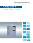
Motors | Automation | Energy | Transmission & Distribution | Coatings CFW701 HVAC Frequency Inverter www.weg.net CFW701 HVAC - Frequency Inverter The CFW701 HVAC is a variable-speed drive intended for use with asynchronous motors for heating, ventilation, air conditioning and refrigeration applications. Offering excellent cost-effectiveness, the CFW701 HVAC follows the CFW700 topology with plug and play technology, accessories incorporated into the standard version and simple operation. Grouped in 5 frame sizes A to E with accessories to meet NEMA type1 and IP21 enclosures, power ratings cover 0.5 - 75 HP (0.18 - 55 kW) at 230 V, 0.55 – 110kW at 380V, 0.5 - 150 HP (0.55 - 110 kW) at 460 V and 2 - 150 HP (1.5 - 110kW) at 575 V. The CFW701 HVAC drive is a perfect fit for fans, exhausters and pumps located in schools, universities, hospitals, commercial buildings, shopping malls and many other applications where speed contol is required giving considerable energy savings. Comprehensive motor protection is included. Using an intelligent thermal management algorithm drive and motor have separate monitoring parameters providing optimised motor and drive protection. Focusing on meeting both low levels of harmonic distortion and electromagnetic interference (RFI) the CFW701 HVAC drive is factory equipped with RFI filters (C3 level) and symmetrically connected DC link chokes equivalent to a 6% impedance line reactor. Low harmonics and RFI mean low losses, low losses mean less oversizing of circuit components and all of these together lead to high system efficiency. Additionally, the DC link chokes eliminate the minimum impedance requirement needed when installing a VSD. Illustrative image Certifications Technology Human Machine Interface Used for controlling, viewing and setting all the parameters of the CFW701 HVAC. It has specific engineering units for HVAC applications and status indicators that simplify its configuration and operation. It features two operating modes: monitoring and parameterization with optional remote mounting (up to 10 meters). Vectrue Technology® Control Technology of WEG Frequency Inverters Scalar, V/F linear or adjustable - Motor speed controlled with slip compensation VVW - Voltage Vector WEG - Motor speed control with automatic adjustment to load and line varitions 2 CFW701 HVAC - Frequency Inverter www.weg.net Energy Saving The future depends on conscious and sustainable actions as the world grows rapidly. For this, modern and automated solutions are required. Technology is already present in our lives, and in order to produce the energy that drives all the innovations, somebody has to foot the bill. What are you doing to grow sustainably? 42% of the energy consumed worldwide today is used by industry. 68% of the energy used in industry is consumed by electric motors. Save even more energy by using the CFW701 HVAC Frequency Inverters together with the W22 Premium efficiency motors, which have the best efficiency on the market. This solution can help you reduce power consumption by approximately 15%, thus contributing to the sustainable development of our planet. Use energy in a conscious way Go Green! Visit the WEG website to calculate energy savings and investment payback achieved by the use of CFW701 VSD: CFW701 HVAC - Frequency Inverter 3 www.weg.net Ratings Power supply 230 V single-phase: Rated output current 6 to 10 A (1.5 to 3 HP - 1.5 to 3 kW). W). 220 V three-phase: Rated output current 7 to 211 A (0.5 to 75 HP - 0.18 to 55 kW). 380-480 V three-phase: Rated output current 3.6 to 211 A (0.5 to 150 HP - 0.55 to 110 kW). 500-600 V three-phase: Rated output current 2.9 to 150 A (2 to 150 HP - 1.5 to 110kW). Compact structure, ideal for installation in confined spaces High accuracy and reliability of speed control Robust hardware Degree of protection IP20 - standard (IP21 and NEMA1 optional) Hardware Built Into the Product as standard RFI filter (for electromagnetic interference mitigation) LCD HMI Operating interface with backlight Inductors in the DC Link No line reactance required No restrictions for installation, minimum impedance is not required Meets the standard IEC61000-3-12 Inputs and outputs (I/O): 8 Isolated digital inputs 3 Differential analog inputs (0-10 V/4-20 mA (2) and 4-20 mA (1)) 5 Digital outputs (2 relays with NA contacts, 3 isolated transistors) 2 Non-isolated analog outputs 1 Dedicated input for PTC Conformal Coating: Protects electronic boards ensuring better protection against dust, moisture, high temperatures and chemicals that can damage the components According to DIN EN 60068-2-60 Communication protocols through RS-485 interface: BACnet MS/TP, Metasys N2 and Modbus RTU. Intelligent cooling system: Monitoring of the temperature of the Heatsink and the internal air on the electronics boards Monitoring and indication of the fan speed and number of hours of operation Fan is easily removable for cleaning and maintenance. Accessories and Options Operator interface for remote assembly (up to 10 meters) Flash memory module (storage capacity of 1 MB) Safety stop module - It guarantees the blocking of firing circuit so no power is delivered to the motor. It meets EN 954-1 / EN 13849-1, category 3 Standards compliance: EN 61800-5-2:2007, EN ISO 13849-1:2008 + AC:2009, IEC 62061:2005, IEC 61508 Parts 1-7:2010, EN 50178:1997, IEC 60204-1:2005 (in extracts) 4 CFW701 HVAC - Frequency Inverter Inductors L1 and L2 built in the standard CFW701 HVAC www.weg.net Functions Energy Saving Depending on the motor speed and load conditions the flux is automatically reduced, decreasing losses and improving efficiency resulting in energy saving. Fire Mode This function inhibits the drive internal faults allowing the motor to be run under adverse conditions without stopping the process. Bypass For extended full speed operation, the CFW501 HVAC can be used to start the motor direct on line, bypassing the VSD. This improves efficiency and results in energy savings. An external circuit is needed for this operation. Short Cycle Protection Prevents excessive starts. Start delay and time is fully user programmable. Dry Pump Prevents a pump from running with no load. Broken Belt It monitors motor torque and prevents it from running with no load in case of a broken belt. Filter Maintenance Alarm Provides the user with an alarm when a filter is due for replacement. Sleep / Wake-Up Mode Sleep prevents operation of the motor at low speeds. A user selected delay time may be programmed. Wake-up restores the drive to full operation instantaneously when process conditions require operation. PTC A PTC input is standard. Advanced PID Three PID control loops: One controls the process by itself (the one the motor is running) and two are additional PID loops for use to control independent process variables. These could be for the control of external processes not related to what the main PID loop is handling. This eliminates the need for an additional PID controller. SoftPLC Function Available as standard, this function provides the CFW701 HVAC with the functions of a PLC, enabling custom user programs to be created, ensuring flexibility for most HVAC applications. Characteristics Ladder programming language through free of charge software PLC, mathematical and control blocks Access to all parameters of the CFW701 HVAC 90 user parameters can be individually configured to be shown on the keypad of the CFW701 HVAC, allowing units selection, minimum and maximum values, number of decimal digits and other characteristics may be customised Free of Charge Software WLP Software (WEG Ladder Programmer) Main features Communication with the CFW701 HVAC via RS485 interface Logical contacts: normally open and closed, coil, negated coil, set and reset coil, positive and negative transition coil PLC blocks: timer, incremental counter, comparator and arithmetic, PID and filter Monitoring and on-line help Superdrive G2 Software Communication with the CFW701 HVAC via RS485 interface Parameterization, control and monitoring Monitoring and on-line help CFW701 HVAC - Frequency Inverter 5 www.weg.net Applications Hospitals Hospitals Airports Airports Business buildings Business buildings Hotels Hotels Shopping malls Shopping malls 6 CFW701 HVAC - Frequency Inverter www.weg.net Clean rooms Clean rooms Applications Applicationsforfor Fans Fansand andPumps Pumps Clean Rooms Clean Rooms CFW701 HVAC - Frequency Inverter 7 www.weg.net Drive Ratings Normal Duty (ND) Cycle 110% for 60 seconds every 10 minutes Sizing a VFD The correct way to size a VSD is by matching its rated output current with the motor rated current. However, the tables below present the expected motor power for each VSD model. The tables below are a guideline only, as motor rated current may vary with number of poles and manufacturer. Note: Motor power stated in these tables are based on IEC/NEMA standard IV poles motor. Motor Voltage 220 V and 230 V 3Ø 220230 V 3Ø CFW701A06POS2 CFW701A07POS2 CFW701A10POS2 CFW701A06POB2 CFW701A07POB2 CFW701A07POT2 CFW701A10POT2 CFW701A13POT2 CFW701A16POT2 CFW701B24POT2 CFW701B28POT2 CFW701B33POT2 CFW701C45POT2 CFW701C54POT2 CFW701C70POT2 CFW701D86POT2 CFW701D0105POT2 CFW701E0142POT2 CFW701E0180POT2 CFW701E0211POT2 A 6 7 10 6 7 7 10 13 16 24 28 33.5 45 54 70 86 105 142 180 211 60 Hz 230 V HP 1.5 2 3 1.5 2 2 3 3 5 7.5 10 10 15 20 25 30 40 50 60 75 Motor Voltage 500 V and 600 V 8 Model 3Ø 500-600 V Power supply CFW701B02P9T5 CFW701B04P2T5 CFW701B07P0T5 CFW701B10P0T5 CFW701B12P0T5 CFW701B17P0T5 CFW701D22P0T5 CFW701D27P0T5 CFW701D32P0T5 CFW701D44P0T5 CFW701E53P0T5 CFW701E63P0T5 CFW701E80P0T5 CFW701E0107T5 CFW701E0125T5 CFW701E0150T5 Normal Duty (ND) A 2,9 4.2 7.0 10 12 17 22 27 32 44 53 63 80 107 125 150 CFW701 HVAC - Frequency Inverter IEC 50 Hz 525 V ac kW 1.5 2.2 4 5.5 7.5 11 15 18.5 22 30 37 45 55 75 90 110 50 Hz 575 V ac kW 1.5 2.2 4 5.5 7.5 11 15 18.5 22 30 37 45 55 75 90 110 NEMA 60 Hz 575 V ac HP 2 3 5 7.5 10 15 20 25 30 40 50 60 75 100 125 150 Power supply Model 3Ø 200-240 V 1/3Ø 1Ø Model Normal Duty (ND) NEMA 380-480 V Power Supply Motor Voltage 380 V and 460 V IEC 50 Hz 220 V 230 V kW 1.1 1.5 2.2 1.1 1.5 1.5 2.2 3 4 5.5 7.5 9.2 11 15 18.5 22 30 37 55 55 CFW701A03P6T4 CFW701A05P0T4 CFW701A07P0T4 CFW701A10P0T4 CFW701A13P5T4 CFW701B17P0T4 CFW701B24P0T4 CFW701B31P0T4 CFW701C38P0T4 CFW701C45P0T4 CFW701C58P5T4 CFW701D70P5T4 CFW701D88P0T4 CFW701E0105T4 CFW701E0142T4 CFW701E0180T4 CFW701E0211T4 Normal Duty (ND) A 3.6 5 7 10 13.5 17 24 31 38 45 58.5 70.5 88 105 142 180 211 IEC 50 Hz 380 V 415 V kW 1.5 2.2 3 4 5.5 7.5 11 15 18.5 22 30 37 45 55 75 90 110 NEMA 60 Hz 440 V 460 V HP 2 3 4 7.5 10 12.5 15 20 30 30 40 50 75 75 100 150 175 60 Hz 460 V HP 2 3 3 5 7.5 10 15 20 25 30 40 50 60 75 100 150 150 www.weg.net Dimensions, Weight and Temperature NEMA 1 Model CFW701A06POS2 CFW701A07POS2 CFW701A10POS2 CFW701A06POB2 CFW701A07POB2 CFW701A07POT2 CFW701A10POT2 Frame size A H 305 (12.02) W 145 (5.71) IP20 / IP21 Dimensions mm (in) D H 227 (8.94) W 247 (9.73) 145 (5.71) IP20 D Maximum surronding air temperature with no derating °C (°F) _ ND/HD 50 (122)_ND 50 (122)_ND 50 (122)_ND 50 (122)_ND 50 (122)_ND 50 (122)_ND 50 (122)_ND 45 (113)_ND 50 (122) 50 (122)_ND 45 (113)_ND 50 (122)_ND 227 (8.94) CFW701A13POT2 CFW701A16POT2 CFW701B24POT2 CFW701B28POT2 B CFW701B33POT2 CFW701C45POT2 CFW701C54POT2 CFW701C70POT2 CFW701D86POT2 CFW701D0105POT2 C D CFW701E0142POT2 CFW701E0180POT2 CFW701E0211POT2 E 351 (13.82) 190 (7.46) 227 (8.94) 293 (11.53) 190 (7.46) 227 (8.94) 448.1 (17.64) 220 (8.67) 293 (11.52) 378 (14.88) 220 (8.67) 293 (11.52) 550 (21.63) 735 (28.94) 828.9 (32.63) 300 (11.81) 305 (12.00) 504 (19.84) 300 (11.81) 305 (12.00) 335 (13.2) 358 (14.1) 620 (24.4) 335 (13.2) 358 (14.1) A 305 (12.02) 145 (5.71) 227 (8.94) 247 (9.73) 145 (5.71) 227 (8.94) B 351 (13.82) 190 (7.46) 227 (8.94) 293 (11.53) 190 (7.46) 227 (8.94) C 448.1 (17.64) 220 (8.67) 293 (11.52) 378 (14.88) 220 (8.67) 293 (11.52) 550 (21.63) 735 (28.94) 828.9 (32.63) 300 (11.81) 305 (12.00) 504 (19.84) 300 (11.81) 305 (12.00) 335 (13.2) 358 (14.1) 620 (24.4) 335 (13.2) 358 (14.1) CFW701A10P0T4 CFW701A13P5T4 CFW701B17P0T4 CFW701B24P0T4 CFW701B31P0T4 CFW701C38P0T4 CFW701C45P0T4 CFW701C58P5T4 CFW701D70P5T4 CFW701D88P0T4 CFW701E0105T4 CFW701E0142T4 CFW701E0180T4 CFW701E0211T4 CFW701B02P9T5 CFW701B04P2T5 CFW701B07P0T5 CFW701B10P0T5 CFW701B12P0T5 CFW701B17P0T5 CFW701D22P0T5 CFW701D27P0T5 CFW701D32P0T5 CFW701D44P0T5 CFW701E53P0T5 CFW701E63P0T5 CFW701E80P0T5 CFW701E0107T5 CFW701E0125T5 CFW701E0150T5 D E B 351 (13.82) 190 (7.46) 227 (8.94) 293 (11.53) 190 (7.46) 227 (8.94) D 550 (21.63) 300 (11.81) 305 (12.00) 504 (19.84) 300 (11.81) 305 (12.00) E 735 (28.94) 335 (13.2) 358 (14.1) 620 (24.4) 335 (13.2) 358 (14.1) 50 (122)_ND 50 (122)_ND 50 (122)_ND 50 (122)_ND 50 (122)_ND 50 (122)_ND 45 (113)_ND 50 (122)_ND 50 (122)_ND 45 (113)_ND 45 (113)_ND 50 (122)_ND 45 (113)_ND 50 (122) 50 (122)_ND 40 (104)_ND 50 (122)_ND 45 (113)_ND 50 (122) 50 (122)_ND 50 (122)_ND 50 (122)_ND 50 (122)_ND 50 (122)_ND 45 (113)_ND 45 (113)_ND 45 (113)_ND 45 (113)_ND 45 (113)_ND 45 (113)_ND 50 (122)_ND 50 (122)_ND 45 (113)_ND 50 (122) 45 (113)_ND 50 (122)_ND 50 (122)_ND 50 (122)_ND 50 (122)_ND 50 (122)_ND 50 (122)_ND 50 (122)_ND 50 (122)_ND 40 (104)_ND 50 (122) 45 (113)_ND 50 (122)_ND 50 (122)_ND 40 (104)_ND 45 (122) 50 (122)_ND 50 (122)_ND 50 (122)_ND 50 (122)_ND 50 (122)_ND 50 (122)_ND 45 (113)_ND 45 (113)_ND 45 (113)_ND 45 (113)_ND 50 (122)_ND 50 (122)_ND 45 (113)_ND 45 (113)_ND 45 (113)_ND 45 (113)_ND 50 (122)_ND 50 (122)_ND 50 (122)_ND 50 (122)_ND 50 (122)_ND 50 (122)_ND 50 (122)_ND 50 (122)_ND 50 (122)_ND 50 (122)_ND 45 (113)_ND 45 (113)_ND 45 (113)_ND 45 (113)_ND 45 (113)_ND 45 (113)_ND 50 (122)_ND 50 (122)_ND 50 (122)_ND 50 (122)_ND 50 (122)_ND 50 (122)_ND 50 (122)_ND 50 (122)_ND 50 (122)_ND 50 (122)_ND 45 (113)_ND 45 (113)_ND 45 (113)_ND 45 (113)_ND 45 (113)_ND 45 (113)_ND 50 (122)_ND CFW701A03P6T4 CFW701A05P0T4 CFW701A07P0T4 NEMA 1 / IP21 50 (122)_ND Weight kg (lb) Braking IGBT 6.3 (13.9) Standard 10.4 (22.9) 20.5 (45.2) 32.6 (71.8) 650 (143.3) Optional 6.3 (13.9) 10.4 (22.9) Standard 20.5 (45.2) 32.6 (71.8) 65.0 (143.3) Optional 10.4 (22.9) Standard 32.6 (71.8) Optional 65.0 (143.3) H Note: Weight data is for the VSD as IP20 enclosure, if IP21 and NEMA1 kits are being added the total weight will change. Consult the user manual for additional information. D w CFW701 HVAC - Frequency Inverter 9 www.weg.net Coding Model identification Product and series Frame size Rated current No. of phases Rated voltage CFW701 A 03P6 T 2/4/5 Braking ¹ Degree of protection ¹ Conducted emission level ¹ Safety stop ² External power supply for control NB 20 C3 Y1 W1 Check table below NB = Braking IGBT not available DB = Braking IGBT available CFW701 20 = IP20 21 = IP21 ( not available for frame size E ) N1 = Nema1 Enclosure * Check table " enclosures " at chapter " Accessories ". C3 = According to category 3 of IEC 61800-3 standard Blank = with no STO function Y1 = with STO function according to EN 954-1 / ISO 13849-1, category 3 Blank = with no External Power supply board W1 = Control circuit is supplied through an external 24 V power supply (1) All the CFW701s come equipped with RFI filter as standard. (2)This option is not available for models frame size A with the option for Nema1. Frame sizes output current (ND) 06P0 = 6.0 A 07P0 = 7.0 A Input Power supply voltage Braking 2 = 200...240 V DB Degree of protection Conducted emission level B = single/three phase power supply 06P0 = 6.0 A 07P0 = 7.0 A A S = single phase power supply 10P0 = 10 A 07P0 = 7.0 A 10P0 = 10 A 20 13P0 = 13 A 16P0 = 16 A 24P0 = 24 A B 28P0 = 28 A 33P5 = 33.5 A 45P0 = 45 A C S = three phase power supply 54P0 = 54 A 70P0 = 70 A D 86P0 = 86 A N1 0105 = 105 A 0142 = 142 A E 0180 = 180 A 2 = 220...230 V NB 0211 = 211 A 06P0 = 6.0 A 07P0 = 7.0 A 06P0 = 6 A 07P0 = 7.0 A A C3 B = single/three phase power supply 2 = 200...240 V S = single phase power supply 10P0 = 10 A 3P6 = 3.6 A 05P0 = 5.0 A 20 07P0 = 7.0 A 10P0 = 10 A DB 13P5 = 13.5 A 17P0 = 17 A B 24P0 = 24 A 31P0 = 31 A 38P0 = 38 A C T = three phase power supply 4 = 380...480 V 45P0 = 45 A 58P5 = 58.5 A D 70P5 = 70.5 A N1 88P0 = 88 A 0105 = 105 A E 0142 = 142 A 0180 = 180 A 0211 = 211 A 10 CFW701 HVAC - Frequency Inverter NB 20 www.weg.net Coding Frame sizes output current (ND) Input Power supply voltage Braking Degree of protection DB 20 Conducted emission level 2P9 = 2.9 A 4P2 = 4.2 A B 7P0 = 7 A 10P0 = 10 A 12P0 = 12 A 17P0 = 17 A 22P0 = 22 A D 27P0 = 27 A 32P0 = 32 A T = three phase power supply N1 5 = 500...600 V C3 44P0 = 44 A 53P0 = 53 A 63P0 = 63 A E 80P0 = 80 A 0107 = 107 A NB 20 0125 = 125 A 0150 = 150 A Options “Options” mean factory installed hardware, no field installation is possible. Below are the available hardware options: Dynamic Braking CFW701 HVAC frame sizes A to D come equipped with braking IGBT in the standard product. For frame size E a specific version has to be chosen, “DB” has to be part of the coding. See page 10. IP21/ NEMA1 Enclosure The CFW701 HVAC standard version comes IP20, IP21/NEMA1 are available as optional. See page 10 for coding information. Safety Stop Module It prevents accidental operation of the motor According to ISO13849-1 and EN954-1 / Category 3 After the activation of the safety stop function, the PWM pulses in the output of the CFW701 HVAC are blocked and the motor stops by inertia. With this function active, you cannot start the motor or create a rotating magnetic field in it, even if there is an internal fault. In order to select the safety module, insert “Y1” in position 9 of the smart code. 24 V dc External Power Supply for Feeding Control Circuitry This option comes from the factory with a board in the power circuit allowing an external 24VDC control supply to power the VSD control. CFW701 HVAC - Frequency Inverter 11 www.weg.net Accessories Reference Description Slot Control accessories USB - RS485/232 UBS / RS485/232 converter kit - Operating interface and accessories HMI-03 Separate standard product operating interface - RHMIF-03 Frame kit for operating interface remote mounting (degree of protection IP56) - HMID-01 Blind cover - HMI cable 1 m Cable set for serial remote operating interface 1 m HMI cable 2 m Cable set for serial remote operating interface 2 m HMI cable 3 m Cable set for serial remote operating interface 3 m HMI cable 5 m Cable set for serial remote operating interface 5 m HMI cable 7.5 m Cable set for serial remote operating interface 7.5 m HMI cable 10.0 m Cable set for serial remote operating interface 10.0 m KN1A-02 NEMA conduit kit for size A KN1B-02 NEMA conduit kit for size B - - Others 12 KN1C-02 NEMA conduit kit for size C KN1E-01 NEMA conduit kit for size E (CFW110142T2 / CFW110142T4 e CFW11105T4) KN1E-02 NEMA conduit kit for size E (CFW110180T2, CFW110180T4 / CFW110211T2, CFW110211T4) KIP21A-01 IP21 Kit for size A KIP21B-01 IP21 Kit for size B KIP21C-01 IP21 Kit for size C KIP21D-01 IP21 Kit for size D PCSA-01 Power cable shield kit for size A PCSB-01 Power cable shield kit for size B PCSC-01 Power cable shield kit for size C PCSD-01 Power cable shield kit for size D PCSE-01 Power cable shield kit for size E CCS-01 Power cable shield kit - included in the standard product CONRA-03 Control rack with card CC701.CDE DBW-03 Braking module DBW030380D3848SZ CCK-01 Output relay module CFW701 HVAC - Frequency Inverter - - - - - www.weg.net Technical Specifications Frequency Inverter CFW701 HVAC Imposed voltage Control types - V/F Scalar - VVW: Voltage Vector Control Method Control Output frequency Performance Speed control REF (XC1:21-24) User’s power supply (CC701 board) +5 V (XC1:1-8) +24 V Analog Inputs (CC701 board) Digital Analog Outputs (CC701 board) Relay Transistor Safety Operating interface (HMI) Protection Standard PWM SVM (Space Vector modulation) Current, flux and speed Controllers in software (Full digital) Execution rate - Current controllers: 0.2 ms (5 KHz) - Flux controllers: 0.4 ms (2,5 KHz) - Speed controller / speed measurement: 1.2 ms 0 to 3.4 x motor rated frequency (P0403). The motor rated frequency is adjustable from 0 Hz to 300 Hz in the V/F and VVW modes and 30 to 120 Hz in the vector mode Maximum output frequency limit considering the switching frequency - 125 Hz (Switching frequency = 1.25 KHz) - 200 Hz (Switching frequency = 2 KHz) - 250 Hz (Switching frequency = 2.5 KHz) - 500 Hz (Switching frequency = 5 KHz) V/F (Scalar): Control (with slip compensation): 1% of the normal speed . Speed variation range: 1:20 VVW: Control: 1% of the rated speed Speed variation range: 1:30 Power supply of 10 V + 10% to be used with potentiometer in the analog inputs Maximum output current: 2 mA Power supply of 5 V + 5% Maximum output current: 160 mA Power supply of 24 V + 10% to be used with digital inputs and outputs Maximum output current: 500 mA 3 differential inputs Resolution: 11 bits + signal Input level: (0 to 10) V, (-10 to 10) V, (0 to 20) mA or (4 to 20) mA (1) Impedance: 400 kΩ for voltage input, 500 Ω for current input Maximum voltage allowed in the inputs: +15 V Programmable functions 8 isolated digital inputs 24 V dc (High level > 10 V, Low level < 2 V) Maximum inut voltage + 30 V dc Input impedance: 2 kΩ Active high or active low input selectable by jumper (simultaneous selection for all the inputs 2 non-isolated outputs Output in voltage (0 to 10 V) or current (0/4 mA to 20 mA) Maximum load: RL > 10 kΩ (voltage) or RL < 500 Ω (current). Resolution: 10 bits Programmable functions 2 relays with NA contacts Maximum voltage: 240 V / 30 V dc Maximum current: 0.75 A Programmable functions 3 isolated digital outputs open sink (they use the same reference as the 24 V supply) Maximum current: 80 mA Maximum voltage: 30 V dc (2) Programmable functions Overcurrent/short-circuit in the output Power under/overvoltage Phase loss Overtemperature in the heatsink/internal air Overload on the IGTBs Overload on the motor External fault/alarm Fault on the CPU or memory Short-circuit phase-ground on the output 9 keys: Run/Stop, Increment, Decrement, Direction of Rotation, Jog, Local/Remote, BACK, ESC and ENTER/MENU LCD Allows accessing/changing all the parameters Accurate indications: - Current: 5% of the rated current - Speed resolution: 1 RPM Can be mounted externally (remote mounting) (1) Input levels for AI3 only (0 to 20) mA and (4 to 20) mA. (2) The transistor outputs feature an internal freewheel diode for +24 V. CFW701 HVAC - Frequency Inverter 13 www.weg.net Technical Specifications Degree of protection IP20 Models size A, B, C without top cover and Nema1 kit Models size E without Nema1 kit IP20 Models size D without IP21 kit Models size E with Nema1 kit (KN1E-01 and KNE1-02) IP21 Models size A, B and C with top cover NEMA1/IP21 IP54 Safety standards Electromagnetic compatibility standards Mechanical construction standards 14 Models size A, B and C with top cover and Nema 1 kit Models size D with IP21 kit Back part of the CFW701 HVAC (external part for flange mounting) UL 508C - Power conversion equipment UL 840 - Insulation coordination including clearances and creepage distances for electrical equipment EN 61800-51 - Safety requirements electrical thermal and energy EN 50178 - Electronic equipment for use in power installations EN 60204-1 - Safety of machinery. Electrical equipment of machines. Part: General requirement Nota: For a machine to comply with this standard, the manufacturer of the machine is responsible for installing an emergency stop device and a device for disconnection from the power line EN 60146 (IEC) - Semiconductor converters En 61800-2 - Adjustable speed electrical power drive systems - Part 2: General requirements - Ratings specifications for low voltage adjustable frequency AC power drive systems EN 61800-3 - Adjustable speed electrical power drive systems - Part 3: EMC product standard including specific test methods EN 55011 - Limits and methods of measurement of radio disturbance characteristics of industrial, scientific and medical (ISM) radio-frequency equipment CISPR11 - Industrial, scientific and medical (ISM) radio-frequency equipment - Electromagnetic disturbance characteristics - Limits and methods of measurement EN 61000-4-2 - Electromagnetic Compatibility (EMC) - Part 4: Testing and measurement techniques - Section 2: Electrostatic discharge immunity test EN 61000-4-3 - Electromagnetic compatibility (EMC) - Part 4: Testing and measurement techniques - Section 3: Radiated, radio-frequency, electromagnetic field immunity test EN 61000-4-4 - Electromagnetic compatibility (EMC) - Part 4: Testing and measurement techniques - Section 4: Electrical fast transient/burst immunity test EN 61000-4-5 - Electromagnetic compatibility (EMC) - Part 4: Testing and measurement techniques - Section 5: Surge immunity test EN 61000-4-6 - Electromagnetic compatibility (EMC) - Part 4: Testing and measurement techniques - Section 6: Immunity to conducted disturbances, inducted by radio-frequency fields EN 60529 - Degrees of protection provided by enclosures (IP code) UL 50 - Enclosures for electrical equipment CFW701 HVAC - Frequency Inverter www.weg.net Technical Data Single phase Voltage 200-220 V ac (+10 %-15 %) 200-220 V ac (+10 %-15 %) Three phase 380-480 V ac (+10 %-15 %) Single phase 1.5 to 3 HP (1.1 to 2.2 kW) 500-600 V ac (+10%-15%) Voltage and rating features Power Three phase 1.5 to 75 HP (1.1 to 55 kW) 2 to 150 HP (1.5 to 110 kW) Frequency 50...60 Hz (+/-2%_48 to 63 Hz) Displacement factor Greater than 0.98 Efficiency Greater than 0.97 Power factor 0.94 for three phase input at nominal conditional 0.70 for single phase input at nominal conditional Frequency range 0 to 3.4x motor rated frequency (P0403). The rated frequency is programable up to 300 Hz (V/Hz) and 120 Hz (vector mode). Switching Frequency data must be observed for speed limits. Standard: 5 kHz ( A, B, C D frames) 2.5 kHz for all 380 V models frame E Switching frequency Control 2.5 kHz for frame E 220 V models 142/180 Amps (ND) 2.5 kHz for frame E 220 V model 211 Amps (ND/HD) 5 kHz for frame E 220 V models 142/180 Amps (HD) Available options for 2.5 / 5 / 10 kHz ( check for derating) Overload Normal Duty (ND) 110% for 1min every 10 min Aceleration 0 to 999 s Deceleration 0 to 999 s -10 to 50 °C (14 to 122 °F) for most of models. For operating temperature of each model the table " Dimensions, Weight and Temperature" shall be checked. Temperature -10...60ºC for frames A, B, C and D (up to 45 °C without derating for models 13 A and 24 A/200...240 V, 7 and 10 A/380...480 V and up to 50 °C without derating for the other models) and-10...55 °C for frame E (up to 45 °C without derating). If derating has to be considered have 2% current reduction for each °C above the specific operating temperature. Humidity 5 to 90% with no condensation Environment Altitude Braking methods 0 to 1000 meters with no derating Up to 4000 meters with current reduction of 1% for each 100 meters above 1000 meters Dynamic braking Available as standard for frame sizes A, B, C and D for 460 V and D for 600 V. For frame size E "DB" models has to be used. An extra resistor must be fitted in for dynamic braking capability. Optimal braking There is no need for braking resistor DC braking DC Current applied to motor Regulation: 1% of rated speed V/f Performance Speed control Voltage Vector VVW Analog Relay I/Os Output 8 x isolated bidirectional 24 V 2 x +/-10V, 11 bits + signal (differencial) or 0/4...20 mA, 11 bits (differencial) Impedance: 400 kΩ for voltage signal / 500Ω for current signal 2 x relay NO/NC contact (240 V ac/1 A) 4 x open drain (24 V/200 mA) 1 x 0/4 - 20 mA 11bits Analog 24 V power supply capacity Regulation: 1% of rated speed Speed Variation range 1:30 Digital Inputs Speed Variation range 1:20 2 x 0...10 V or 0/4...20 mA, 11 bits (not isolated from inverter ground) 500 mA (available for the user, including I/Os) CFW701 HVAC - Frequency Inverter 15 www.weg.net Technical Data Communication Modbus RTU RS485 built-in ( Available in control terminals) BACnet MS/TP RS485 built-in / Superdrive and WLP communication Metasys N2 UL 508C Power conversion equipment UL 840 Insulation coordination including clearences and creepage distances for electrical equipment EN61800-5-1 - Safety requirements electrical, thermal and energy. EN 50178 - Electronic equipment for use in power installations. Safety standards EN 60204-1 - Safety of machinery. Electrical equipment of machines. Part 1: General requirements. In order to have a machine in conformity with this regulation, the machine builder is resposible forthe installation of na emergency shutdown device and na equipment for power disconnection. EN 60146 (IEC 146) - Semiconductor converters. EN 61800-2 - Adjustable speed electrical power drive systems - Part 2: General requirements - Rating specifications for low voltage adjustable frequency A.C. power drive systems EN 60529 - Degrees of protection provided by enclosures (IP code). UL 50 - Enclosures for electrical equipment EN 61800-3 - Adjustable speed electrical power drive systems - Part 3: EMC product standard including specifc test methods. EN 55011 - Limits and methods of measurement of radio disturbance characteristics of undustrial, scientific and medical (ISM) radio-frequency equipment. Mechanical Construccion Standards Eletromagnetic Compatibility Standards (EMC) CISPR 11 - Industrial, scientifc and medical (ISM) radio-frequency equipment - Eletromagnetic disturbance characteristics - Limits and methods of measurement. EN 61000-4-2 - Electromagnetic compatibility (EMC) - Part 4: Testing and measurement techniques - Section 2: Eletrostatic discharge immunity test. EN 61000-4-3 - Electromagnetic compatibility (EMC) - Part 4: Testing and measurement techniques - Section 3: Radiated, radiofrequency, electromagnetic feld immunity test. EN 61000-4-4 - Electromagnetic compatibility (EMC) - Part 4: Testing and measurement techniques - Section 4: Electrical fast transient/burst immunity test. EN 61000-4-5 - Electromagnetic compatibility (EMC) - Part 4: Testing and measurement techniques - Section 5: Surge immunity test. EN 61000-4-6 - Electromagnetic compatibility (EMC)- Part 4: Testing and measurement techniques - Section 6: Immunity to conducted disturbances, induced by radio-frequency fields. Overcurrent / Short circuit Under / Overvoltage in the power section Phase loss VSD thermal overload ( IGBTs, rectifier and in the eletronics) Motor thermal overload Braking resistor overload Protections IGBTs overload Motor overload Fault / external alarm CPU failure Phase-to ground short circuit at the output Failure at the heatsink fan Motor overspeed Wrong connection of encoder wiring 16 CFW701 HVAC - Frequency Inverter www.weg.net Block Diagram DC link connection Braking resistor connection Filter C3 (*) Braking IGBT (available in the inverters CFW701...DB...) Capacitor bank DC link Three-phase rectifier DC link inductors Precharge Power Supply Inverter with IGBT transistors RFI Filter CONTROL POWER Feedback: - Voltage - Current Sources for electronics and interfaces between Power and control Software WLP and SuperDrive G2 Digital Inputs DI1 to DI8 Control Board with 32-bit “RISC” CPU Analog Inputs AI1 to AI3 Analog Outputs AO1 and AO2 Digital Outputs DO1 (RL1) and DO2 (RL2) FLASH Memory (Slot 5) Digital Outputs DO3 to DO5 PTC Input 3 = Man-machine interface (*) The capacitor against the ground filter C3 (in the models size A, it is possible to meet category C2) must be disconnected for IT networks and grounded delta. Refer to the input connections. Block diagram of the CFW701 HVAC CFW701 HVAC - Frequency Inverter 17 www.weg.net Notes 18 CFW701 HVAC - Frequency Inverter www.weg.net Notes CFW701 HVAC - Frequency Inverter 19 www.zest.co.za Johannesburg Rustenburg Zest Electric Ghana Limited 47 Galaxy Avenue, Linbro Business Park Private Bag X10011, Sandton 2146 GPS: S 26º 4’ 10.92” E 28º 6’ 45.88” Tel: +27 (0) 11 723 6000 Fax: +27 (0) 11 723 6001 [email protected] 6 Kgwebo Road, Mabe Business Park Old Pretoria Road P O Box 649, Rustenburg 0300 GPS: S 25º 41’ 14.1” E 27º 15’ 38.78” Tel: +27 (0) 14 594 0450 Fax: +27 (0) 14 594 0471 [email protected] 15, Third Close Street, Airport Residential Area, Accra, Ghana GPS: N 5º 36’ 54.90” W 0º 10’ 50.02” Tel: +233 30 27 664 90 Fax: +233 30 27 664 93 Cell: +233 540 898 466 [email protected] Generator Set Division Johannesburg Port Elizabeth EnI Electrical Electrical/Instrumentation Engineering and Contracting 47 Galaxy Avenue, Linbro Business Park GPS: S 26º 4’ 10.92” E 28º 6’ 45.88” Tel: +27 (0) 11 723 6000 Fax: +27 (0) 11 723 6001 [email protected] 55 Burman Road, Deal Party P O Box 2565, North End 6056 GPS: S 33º 54’ 15.7” E 25º 36’ 50.3” Tel: +27 (0) 41 486 1262 Fax: + 27 (0) 41 486 1658 [email protected] Cape Town Richards Bay 9 Omuramba Road, Marconi Beam Montague Gardens, Milnerton P O Box 36582, Chempet 7442 GPS: S 33º 52’ 42.1” E 18º 30’ 39.1” Tel: +27 (0) 21 551 2710 Fax: +27 (0) 21 551 2776 [email protected] 5 Brass Link, Unit 1A, Alton P O Box 30206, Richards Bay 3900 GPS: S 28º 45’ 3.02” E 32º 1’ 47.82” Tel: +27 (0) 35 751 1607 Fax: +27 (0) 35 751 1426 [email protected] 13 Benbow Avenue, Epping Industrial 1 P O Box 231, Eppingdust, 7475 GPS: S 33º 55’ 48.65” E 18º 32’ 12.6” Tel: +27 (0) 21 507 7200 Fax: +27 (0) 21 507 7201 [email protected] Durban 51 Island Circle, Riverhorse Business Estate P O Box 20667 Durban North 4016 GPS : S 29º 46’ 5.53” E 31º 0’ 21.04” Tel: +27 (0) 31 569 7260 Fax: +27 (0) 31 569 6755 [email protected] 3 Schabort Street, Trichardt P O Box 1626, Secunda 2302 GPS: S26º 29’ 28.08” E29º 13’ 15.64” Tel: +27 (0) 17 638 1571 Fax: +27 (0) 17 638 1572 [email protected] Middelburg 6 Wicht Street, Vaalbank, Middelburg GPS: S 25º 47’ 7.70” E 29º 28’ 42.33” Tel: +27 (0) 13 246 2849 Fax: +27 (0) 13 246 2850 [email protected] Shaw Controls Motor Control Centres, Packaged Switchgear Solutions 18 Mt. Ida Road, Robertsham P O Box 39195, Booysens 2016 GPS: S 26º 14’ 43.8” E 28º 00’ 59.3” Tel: +27 (0) 11 680 4534 Fax: +27 (0) 11 433 3569 [email protected] Zest Energy Integrated Power Generation, Co–Generation and Energy Solutions 21 Galaxy Avenue, Linbro Business Park Private Bag X10011, Sandton 2146 GPS: S 26º 4’ 23.4” E 28º 6’ 49.5” Tel: +27 (0) 11 723 6000 Fax: +27 (0) 11 723 6001 [email protected] WEG Transformers Africa Locally Manufactured Transformers and MiniSubstations 38 Van Deventer Street, Wadeville Germiston GPS: S 26º 15.941’ E 28º 12.46’ Tel: +27 (0) 11 827 3458 Fax: +27 (0) 11 827 1668 [email protected] Cod: 50041190 | South Africa | Rev: 00 | Date (m/y): 06/2015 The values shown are subject to change without prior notice. Trichardt Generator Set & Panel Division Cape Town 47 Galaxy Avenue, Linbro Business Park Private Bag X10011, Sandton 2146 GPS: S 26º 4’ 10.92” E 28º 6’ 45.88” Tel: +27 (0) 11 792 2803 Fax: +27 (0) 11 723 6001 [email protected]