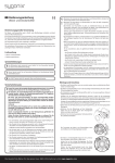
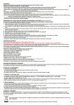
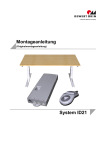
1
MEGAMAT 5 (MFZ) CARE, HOSP Installation Instructions (Translation of the original installation instructions) MEGAMAT MFZ Foreword Foreword Document revision history Version Date Modification, change (-) 04/11 First release (a) 07/12 Edition II (b) 11/12 LR / lifter release (c) 03/13 GQR (d) 09/13 Installation of LR / lifter release Disclaimer and exclusion of liability DewertOkin is not responsible for damage resulting from: • failure to observe these instructions, • changes made to this product which have not been approved by DewertOkin, or • the use of replacement parts which have not been approved or manufactured by DewertOkin. Manufacturer's address DewertOkin GmbH Weststraße 1 32278 Kirchlengern, Germany Germany Tel: +49(0)5223/979-0 Fax.: +49 0 522375182 http://www.dewertokin.de [email protected] Creation of a complete operating instruction manual for the entire end product These instructions are only intended to be used by the end-product manufacturer. They should not be given to the operator of the end product. The factual information contained within may be used as a basis when creating the end-product manual. The warning and danger notices are best suited for use in the end product's manual. However it is not sufficient to simply follow these notices. You should also carry out an internal risk assessment for your end product. This can then be used as the basis for the safety notices in your manual. These installation instructions do not contain all information required to safely operate the end product. They only describe the installation and operation of the drive as partially completed machinery. The instructions are intended for the technicians responsible for manufacturing an end product and not for the operators of the end product. 68004(d) 3 Foreword MEGAMAT MFZ Notice for customers in EU nations German Inspection Authority (TÜV) testing label The construction of the MEGAMAT MFZ has been inspected by the German Inspection Authority (TÜV). The TÜV also monitors the production of the MEGAMAT MFZ. The official German TÜV label certifies this construction inspection and production monitoring. Figure 1 4 The TÜV label 68004(d) MEGAMAT MFZ Table of contents Table of contents Foreword 3 Document revision history 3 Disclaimer and exclusion of liability 3 Manufacturer's address 3 Creation of a complete operating instruction manual for the entire end product 3 Notice for customers in EU nations 4 Table of contents 5 1. General Information 7 1.1 Configurations 7 1.2 About these installation instructions 7 1.3 Availability of this document 7 1.4 Conventions used 8 2. Safety Instructions 9 2.1 Proper and Intended Usage 9 2.2 Safety notices within the installation instruction and the operating instructions for the entire machine 10 2.3 Selection and qualification of personnel 10 2.4 Notice on safety during operations 11 2.5 Product identification 12 3. Possible Combinations 14 4. Description 15 4.1 Components 15 5. Technical Specifications 21 6. Installation 25 6.1 Safety notices to observe during installation 25 6.2 Installation procedure 27 7. Operating Notes 41 7.1 General information 41 7.2 Notice for operating with optional configuration 42 8. Troubleshooting 46 68004(d) 5 General Information MEGAMAT MFZ 9. Maintenance 48 9.1 Maintenance 48 9.2 Cleaning and care 49 10. Disposal 50 Declaration of incorporation/installation 51 EU Declaration of Conformity 52 Additional information 53 6 68004(d) MEGAMAT MFZ General Information 1. General Information 1.1 Configurations The MEGAMAT MFZ drive can be used in several different configurations. The "Possible Combinations" chapter includes information about the different device combinations available. 1.2 About these installation instructions These installation instructions must be followed closely in order to install this drive successfully and safely in the end product. These instructions are not an operating manual for the end product. These instructions will help you to minimize danger, repair costs and down times. They will also help you to maximize the reliability and lifespan of the end product. CAUTION The notices in these instructions must be followed! Following the guidelines during installation and connection procedures will help to minimize: • the risk of accident and injury, and • damage to the drive system or the end product. These installation instructions have been written with due care and attention. However, we cannot guarantee that the data, images and drawings are complete and correct nor do we accept any liability for the information contained therein, unless required by law. We reserve the right to make unannounced technical changes in the course of our continual product improvement process! 1.3 Availability of this document As manufacturer of the end product, you are obligated to comply with Machinery Directive 2006/42/EC. This directive stipulates that the installation instructions must be kept on file for governmental inspection purposes. 68004(d) 7 General Information 1.4 MEGAMAT MFZ Conventions used Notices which do not relate to safety are indicated in these instructions with a triangle: Triangular notice symbol Safety notice explanations DANGER DANGER indicates a hazardous situation which, if not avoided, will result in death or serious injury. WARNING WARNING indicates a hazardous situation which, if not avoided, could result in death or serious injury. CAUTION CAUTION indicates a hazardous situation which, if not avoided, could result in minor or moderate injury. NOTICE NOTICE is used to address practices which are not related to personal injury but may result in damage to the product or surroundings. 8 68004(d) MEGAMAT MFZ Safety Instructions 2. Safety Instructions 2.1 Proper and Intended Usage The MEGAMAT MFZ drive is meant to be installed in an end product. • It provides motor adjustment capabilities for movable furniture. It should be used in conjunction with suitable fittings and mechanics. • It can be used for care purposes (CARE). • It can be used in a hospital (HOSP). • It can be used for raising and lowering persons (as a patient lifter). CAUTION This drive should only be used for the applications described above. Any other form of usage is not permitted and can lead to accidents or destruction of the unit. Such nonapproved applications will lead immediately to the expiration of all guarantee and warranty claims on the part of the end-product manufacturer against the manufacturer. Improper usage Be sure to follow the notices below concerning improper usage. You should include them in your product manual in order to inform the users of your end product. WARNING The MEGAMAT MFZ drive should not be used: • in any environment where combustible or explosive gases or vapours (e.g., anaesthesiology) may be present, • in a moist environment, • outdoors, • in any application that will be cleaned with an automated washing system, • for raising and lowering loads in industrial or technical applications. CAUTION The MEGAMAT MFZ drive may not be operated: • by small children, • by frail or infirm persons without supervision, or • in the proximity of small children. CAUTION You should only use spare parts which have been manufactured or approved by DewertOkin. Only these parts will guarantee a sufficient level of safety. 68004(d) 9 Safety Instructions MEGAMAT MFZ Optional: Mechanical res et function: lifter releas e (L R ) or clevis quick releas e (G QR ) CAUTION The mechanical reset function is not a safety system and does not avert danger. DewertOkin does not guarantee that the drive will function in the event of a power outage. It is always possible to lower the unit using either the lifter release (LR) or the clevis quick release (GQR). If the end-product manufacturer chooses to guarantee the functionality of the end product during a power outage, then the end-product manufacturer is responsible for arranging a mechanism to ensure this functionality. 2.2 Safety notices within the installation instruction and the operating instructions for the entire machine The manufacturer of the end product is only permitted to operate the MEGAMAT MFZ drive (by itself an incomplete machine) • when the end product (for which the MEGAMAT MFZ drive is intended) is in compliance with all protective measures specified in the Machinery Directive 2006/42/EC, and • when the manufacturer expressly declares the compliance of the end product. The manufacturer of the end product must create a manual for the users of that product. The safety notices in the end-product manual must be written based on the end product's risk assessment. 2.3 Selection and qualification of personnel This drive should only be installed into the end product by someone who has completed training in electronic motor assembly or has equivalent qualifications. You should only install this drive when you are qualified to do so. Otherwise, a properly qualified person should be found for this task. 10 68004(d) MEGAMAT MFZ 2.4 Safety Instructions Notice on safety during operations Basic safety rules must be followed in order to ensure that the end product can be continually operated in a safe manner. These rules must be observed while using the end product and while installing the drive. These rules and safety measures can be categorized as follows: • Construction measures before the installation (refer to the "Ensuring operational reliability during installation" section in Chapter "Installation") • Safety fundamentals during the drive installation and during cable and wire routing (refer to the "Safety notices to observe during installation" section in the "Installation" chapter). • Using the drive in intermittent duty (refer to the "General information" section in the "Operating Notes" chapter). • Basic safety rules during operation (refer to the "Operating Notes" Chapter). • The creation of a manual for the end product which contains these and other safety rules. Creating a user's manual The manufacturer of the end product must create a manual for the users of that product. The safety notices in the end-product manual must be written based on the end product's risk assessment. 68004(d) 11 Safety Instructions MEGAMAT MFZ 2.5 Product identification 2.5.1 Type plate A ratings plate on each drive specifies the exact name and serial number of the drive. It also states the technical specifications valid for that particular drive. In particular, you will find the maximum pull force and the maximum push force here. The following illustration shows where the specifications are located on the drive's ratings plate. The ratings plate shown is an example; the specifications for your drive may differ from this illustration. Figure 2 12 Ratings plate example Megamat MFZ Model name xxxxxx Article number 24V Input voltage Max. 7.00A Current consumption Intermittent Operation 2min/18min Intermittent operations: 2 minutes / 18 minutes max. Push Force Push force max. Pull Force Pull force Prod.date Calendar week / year Serial No. Serial number for your drive IPX4 Protection degree 68004(d) MEGAMAT MFZ Safety Instructions Use in dry rooms only! Follow all special disposal instructions! Labelling in accordance with the directives IEC 60601-1 and EN 60601-1, 3rd edition. Conformity mark 2.5.2 Safety symbol The symbol below is attached to the drive and has the following meaning: This symbol indicates that the unit should only be opened by qualified specialists! 68004(d) 13 Possible Combinations 3. MEGAMAT MFZ Possible Combinations The MEGAMAT MFZ single drive can be combined for use with other single drives, double drives or control units. The following basic combinations are possible: • a MEGAMAT MFZ with handset and control unit, • a MEGAMAT MFZ in combination with other drives with an additional control unit or double drive. Systems can be customized by combining drives with the handset and control units as needed. Make sure that you switch off the electricity before connecting any components (connect while in a voltage-free state). DewertOkin has separate system instruction manuals containing all information and instructions needed for these systems. Only a DewertOkin device should be used to control the drive since they have already been verified to work together. A control unit or a double drive is needed to operate the MEGAMAT MFZ single drive. A handset is also required. 14 68004(d) MEGAMAT MFZ 4. Description Description The MEGAMAT MFZ drive is an electrically driven motor that is responsible for moving the end product in a linear direction. This adjustment is created by the in and out movement of a stroke pipe. The movements of the MEGAMAT MFZ drive are controlled using a control unit or a double drive which is connected to a DewertOkin handset. The different drive models vary according to the: • the clevis, • power of the drive, • mounting of the stroke pipe, • electrical connection. We reserve the right to make unannounced technical changes in the course of our continual product improvement process! The "Possible Combinations" Chapter describes the different possible combinations of drives and handsets/hand-held remote controls. You can also ask your supplier or dealer for additional information. 4.1 Components The main components of the MEGAMAT MFZ drive are the motor and the stroke pipe. The stroke pipe is protected by the drive housing when it is retracted. Mounting fixtures are located at the outer end of the stroke pipe and at the opposite end of the drive. They are used to mount the drive in the end product. D A B C E F Figure 3 68004(d) Main components of the MEGAMAT MFZ drive A Clevis (example: stroke pipe clevis) B Stroke pipe C Guidance profile shaft D Motor housing E Electrical connection F Gear clevis 15 Description 4.1.1 MEGAMAT MFZ Stroke pipe options There are two types of stroke pipes available for different types of applications. The stroke pipe can be screwed onto the spindle screw or it can be mounted unattached. The drive only exerts pushing force when the stroke pipe is mounted loosely (unattached). The motions of the drives for these two versions are shown in the following illustrations. CAUTION If the stroke pipe is unattached, then the end product must be designed to prevent the stroke pipe from coming out during operations. This can be accomplished by implementing a fixed end-stop mechanism (refer to the "Safety notices to observe during installation" in the "Installation" chapter). Drive motion Figure 4 Loose fastening nut (stroke pipe not secured): only pushing forces Drive motion Figure 5 16 Stroke pipe screwed onto the spindle screw (attached): both pushing and pulling forces 68004(d) MEGAMAT MFZ 4.1.2 Description Clevis options Clevis versions: Stroke pipe clevis Figure 6 68004(d) Clevis version with stroke pipe clevis 17 Description MEGAMAT MFZ Clevis versions: Clevis quick release (GQR) The clevis quick release (GQR) is a mechanical reset function that is used to manually lower the patient lifter (during a power or voltage outage, for example). CAUTION The mechanical reset function is not a safety system and does not avert danger. B A Figure 7 18 C D The GQR clevis model A Clevis quick release (GQR) B Bowden cable holder C Stroke pipe D Guidance profile shaft 68004(d) MEGAMAT MFZ Description Clevis versions: Lifter release (LR) The lifter release (LR) is a mechanical reset function that is used to manually lower the patient lifter (during a power or voltage outage, for example). CAUTION The mechanical reset function is not a safety system and does not avert danger. NOTICE The MEGAMAT MFZ drive with the mechanical reset function lifter release (LR) has a limited five-year lifespan. The actual duration of use can be determined from the date of production as specified on the ratings plate (refer to section 2.5.1). A B C D E B Figure 8 Clevis version, lifter release (LR) A Clevis (lifter release) B Bearing bushing C Safety clutch on the lifter release D Stroke pipe E Guidance profile shaft NOTICE Both bearing bushings must always be installed in the LR clevis. 68004(d) 19 Description 4.1.3 MEGAMAT MFZ Electrical connection options There are two different electrical connection options available: Connections with a plug-in motor cable (detachable snap-on cap) or a fixed motor cable (non-detachable cap). For the nondetachable cap, the electrical connection is permanently attached at the factory and cannot be opened. With the detachable snap-on cap, the electrical connection may be opened by a qualified specialist. In this case, the snap-on cap has openings on the side, through which a screwdriver can be inserted to release the snap connection. 20 Figure 9 Detachable snap-on cap for plug-in motor cable Figure 10 Fixed cap for fixed motor cable 68004(d) MEGAMAT MFZ 5. Technical Specifications Technical Specifications Rated voltage 24 V DC – 29 V DC Current consumption at rated load Max. 7 A, depending on version (refer to the ratings plate on the drive) Permitted push force Max. 8000 N, depending on version (refer to the ratings plate on the drive) Permitted push force for GQR Max. 3500 N, depending on version (refer to the ratings plate on the drive) Permitted pull force Max. 3000 N, depending on version (refer to the ratings plate on the drive) Release force (for version with clevis quick release, GQR) Approx. 34 kg Rated torque for clevis lifter release Approx. 8 Nm Starting torque for clevis lifter release Approx. 24 Nm 1 Mode of operation under max. rated load. Intermittent duty: 2 min/18 min (max 5 switching cycles per minute) Protection class III Noise level ≤ 65 dB(A) Drive type Single drive Load type Push / pull Type of load (version with lifter release, LR) Pressure Stroke < 300 mm Adjustment speed 2 Protection degree Up to 8 mm/second, depending on the version IP20, IPX4, IPX6 Dimensions and weight 68004(d) Length x width x height Min. 191 mm x 176 mm x 98 mm Length x width x height (for version with lifter release) Min. 261 mm x 176 mm x 98 mm Length x width x height (for version with clevis quick release, GQR) Min. 232 mm x 176 mm x 98 mm Weight Approx. 1.7 kg, depending on version 21 Technical Specifications MEGAMAT MFZ Ambient conditions for operation, storage and transport 22 Transport / storage temperature From -20 °C to +50 °C From -4 °F to +122 °F Operating temperature From +10 °C to +40 °C From +50 °F to +104 °F Relative humidity From 30% to 75% Air pressure From 800 hPa to 1060 hPa Height < 2000 m 1) Mode of operation: intermittent duty = 2 min./18 min. This means that after the unit is operated with its rated load for up to two minutes it must then be paused for 18 minutes. The system can malfunction if this pause is not observed! 2 Adjustment speed: the speed at which the clevis can move under no load (the speed varies depending on the load). 68004(d) MEGAMAT MFZ Technical Specifications 176 98 163 Min. 191 Figure 11 Dimensions of MEGAMAT MFZ drive (in mm), minimum installation dimension: 163 mm 176 98 209 Min. 232 Figure 12 68004(d) Dimensions of MEGAMAT MFZ drive with GQR (in mm), minimum installation dimensions: 209 mm 23 Technical Specifications MEGAMAT MFZ 176 234 Min. 261 Ø 29.5 98 Figure 13 24 Dimensions of MEGAMAT MFZ drive with LR (in mm), minimum installation dimension: 234 mm 68004(d) MEGAMAT MFZ Installation 6. Installation 6.1 Safety notices to observe during installation Basic safety rules must be followed in order to ensure that the end product can be continually operated in a safe manner. These rules must be observed while using the end product and while installing the drive. 6.1.1 Ensuring operational reliability during installation The safety and reliability of the end product containing the DewertOkin drive can be ensured by using the proper construction methods described below. Avoiding fatigue fractures CAUTION Drives that are incorrectly installed can undergo fatigue fractures which then create a risk of injury. • Install the drive in the end product so that it is properly aligned. This will help prevent shear stress. • Do not position the drive at a slanted angle when installing it in the end product. A slanted angle between the intended direction of movement of the end product and the drive's direction will create shear stress and could lead to a fatigue fracture. • Be sure to install the drive so that it can always move freely in all operative states. • You should never screw the stroke pipe into the drive (versions with fixed nuts). Avoiding a pinching hazard CAUTION A stroke pipe is used to provide the drive motion. When designing your end product, you should take this into account with passive safety mechanisms and with the appropriate safety notices in your operating instructions: • Installation methods for ensuring passive safety: Install the MEGAMAT MFZ drive so that none of the positions where shear and pinch hazards exist are accessible externally. When preparing safety notices for the operator, be sure that your operating instructions inform the user of these points. 68004(d) 25 Installation MEGAMAT MFZ Avoiding an over-extension of the stroke pipe (when mounted unattached) CAUTION There must be a fixed mechanical end stop built into the end product for MEGAMAT MFZ drive models where the stroke pipe is not attached to the spindle screw. If no fixed mechanical end stop exists, the stroke pipe can over-extend. This can cause malfunctions, personal injury, and damage to the drive system. Avoiding an overrun of the stop point with the end product Your end product should contain mechanical end stops. These will limit the drive movement and significantly increase operational safety. DewertOkin recommends that you build such mechanical end stops into your end product. If, for technical or cost reasons, you choose not to use end stops, then we strongly recommend the use of an additional safety limit switch whenever the DewertOkin drive is being used for at-risk functions. A safety limit switch will protect the drive from a critical failure and overrun in the event that the top end switch malfunctions. The safety end switch shuts the drive down as soon as the normal end switch is passed over. The safety end switch is integrated directly into the drive and does not require any additional installation. The drive may take up an extra 23 mm when installed with the safety limit switch. NOTICE When installing the optional clevis quick release (GQR), you must use mechanical end stops (both for the upper limit and for the lower limit) in your end product in order to prevent mechanical damage to the drive system. The mechanical end stops or stroke limiters in the end product must be adjusted to fit the retracted and extended dimensions of the drive. Make sure that the drive does not reach the mechanical end stop position before it has been fully extended. 26 68004(d) MEGAMAT MFZ Installation 6.2 Installation procedure 6.2.1 An example installation Before installing the drive, make sure that you are observing all of the safety notices found in the "Safety notices to observe during installation" section. CAUTION The plug for the connecting cable should be unplugged during the installation. C D B B A G E G Figure 14 F Installing the drive (example) A Bracket for securing the drive (on the stroke pipe side) B Mounting bolt C Stroke pipe clevis D Electrical connection / cable E Gear clevis F Bracket for securing the drive (on the motor side) G Safety clip The fitted mounts on the end product should have elongated slots so that the installed position can be adjusted. 68004(d) 27 Installation MEGAMAT MFZ NOTICE The support brackets for the clevises must be in alignment. In the following example, installation of the MEGAMAT MFZ drive into the end product is shown using mounting bolts. Certain details may change based on the variation in use and technical modifications. 1 Push the drive's gear clevis (E) onto the bracket (F). 2 Insert the mounting bolt (B) into the bracket (F). 3 Secure the mounting bolt (B) with the safety clip (G). 1 Figure 15 2 3 Steps for installing the gear clevis (example) CAUTION Versions with fixed nuts: You should never screw the stroke pipe into the drive. A stroke pipe that has been screwed into the drive can result in fatigue fractures. 4 if the stroke pipe clevis/head (C) does not align exactly with the gear clevis (E), the stroke pipe may by unscrewed out of the drive by no more than a half turn. CAUTION Versions with fixed nuts: The stroke pipe may only be turned one half rotation out of the drive. Do not rotate the stroke pipe further out. An over-rotation can lead to unsafe operations. The stroke pipe clevis must not be detached from the stroke pipe! 28 68004(d) MEGAMAT MFZ Installation 5 Attach the stroke pipe clevis (C) using a mounting bolt (B) to the mounting bracket (A). 6 Secure the mounting bolt (B) with the safety clip (G). 7 Now connect the drive to the control unit or the double drive. Ensure that the electrical connection cable (D) cannot be pulled out. 5 Figure 16 6 7 Steps for installing the stroke pipe clevis (example) If the hand switch will be used to control two drives, you must first connect both drives electrically to each other (for example, over a control unit or double drive). Then you can connect the handset. 68004(d) 29 Installation 6.2.2 MEGAMAT MFZ Information on installing the MEGAMAT MFZ drive with clevis quick release (GQR) CAUTION Installation errors (due to deviations in the brackets or fittings, for example) can significantly alter the release forces of the GQR. Improper installation can lead to significantly increased release forces which may far exceed the specifications. Position and alignment of the bracket on the clevis quick release (GQR) The support brackets for the clevis must be properly aligned (refer to Figure 17). If they do not line up, additional lateral forces will be exerted on the drive unit. If the brackets are out of alignment by only one degree, the release forces can increase significantly. Ideally the brackets should be fitted at almost zero degrees alignment. >= 1° Figure 17 30 Position and alignment of the brackets 68004(d) MEGAMAT MFZ Installation Installation position of the clevis quick release (GQR) The release force will increase, for example, if the drive unit is subjected to a lateral force from other attachments. The resulting release force may be far over the specification. (Figure 18 shows a horizontally installed drive unit with a lateral force acting upon it.) Figure 18 68004(d) The effect of the installation position 31 Installation MEGAMAT MFZ Recommended bracket position for the clevis quick release (GQR) The brackets should be aligned precisely with each other. We recommend that only one mounting bracket is used on both sides of the drive ( as shown by A in Figure 19). When two mounting brackets are used, there is a greater risk that they are not properly aligned, resulting in a tilted drive unit. The drive must be firmly attached, but there should also be a certain degree of movability at the mounting points. The drive must be mounted so that it is protected in all positions against twisting and bending. You can also use brackets with two mounting holes (as shown by B in Figure 19), but these must be exactly aligned so that the release force is not increased. The mounting bracket should have an elongated oval hole so that you can compensate for any deviations in the installation dimensions of the drive and your end product. We recommend: an oval slot (as shown by C in Figure 19) should have at least 2 millimetres of extra room. A B C Figure 19 32 Recommended design of bracket 68004(d) MEGAMAT MFZ 6.2.3 Installation Installation of the Bowden cable for the optional mechanical reset function GQR NOTICE When installing the GQR, use a Bowden cable with some type of length compensation mechanism (for example, attach a spring to the Bowden cable). A Figure 20 B C D E Installation of the Bowden cable for the mechanical reset function GQR (optional) A Bowden cable lock mechanism B Groove in the GQR C Bowden cable holder D Bowden cable with length compensation mechanism (e.g. a spring) E Bowden cable sheath 1 Guide the Bowden cable (D) through the slot in the GQR (B). 2 Place the Bowden cable (D) into the cable holder (C). 3 Secure the cable in position using the locking mechanism (A). CAUTION Do not put too much tension on the Bowden cable. An over-strained Bowden cable could cause an accidental adjustment to occur by triggering the mechanical reset function. 68004(d) 33 Installation MEGAMAT MFZ The Bowden cable holder (C) must be pulled until it reaches the end stop (all the way up) in order to ensure that the GQR functions properly. The GQR's clutch opens up when the pull force reaches 110 N. The pull force must not exceed 250 N, otherwise the GQR could be damaged. 4 Mount the Bowden cable to your end product. A spring should be attached to the Bowden cable mechanism to prevent damage to the GQR and to ensure proper function. 5 Verify that the mechanical reset function is functioning properly. 34 68004(d) MEGAMAT MFZ 6.2.4 Installation Information for installing the MEGAMAT MFZ drive with lifter release (LR) in a safe position CAUTION Installation errors (e.g. due to deviations in the brackets or fittings) can significantly alter the release forces of the lifter release (LR) mechanism. Improper installation can lead to significantly increased release forces which may far exceed the specifications. Position and alignment of the bracket on the lifter release (LR) The support brackets for the clevis support at the lifter release (LR) must be properly aligned (refer to Figure 21). If they do not line up, additional lateral (shear) forces will be exerted on the drive unit. If the brackets are out of alignment by only one degree, the release forces can increase significantly. Ideally the brackets should be fitted at almost zero degrees alignment. >= 1° Figure 21 68004(d) Position and alignment of the bracket on the lifter release (LR) 35 Installation 6.2.5 MEGAMAT MFZ Installation of MEGAMAT MFZ drive with lifter release (LR) in the patient lifter (example) B C D E F A E D B Figure 22 G Overview: Installation in the patient lifter (example) A Gear clevis B Safety clip C Bracket for securing the drive (on the stroke pipe side) D Mounting bolt E Bearing bushing (two) F Clevis (LR) G Bracket for securing the drive (on the motor side) CAUTION Electrical components should be connected or disconnected only when the mains power plug and the battery plug (when present) are both unplugged. 36 68004(d) MEGAMAT MFZ Installation Certain details may change as a result of technical changes. 1 Push the drive's gear clevis (A) onto the bracket (G). 2 Insert the mounting bolt (D) into the bracket (G). 3 Secure the mounting bolt (D) with the safety clip (B). 1 Figure 23 2 3 Steps for installing the gear clevis (example) 4 When the LR clevis (F) is not properly aligned with the gear clevis (A) then it must be re-aligned. NOTICE Both bearing bushings must always be installed in the LR clevis. 5 Make sure that both bearing bushings (E) are installed on the LR clevis (F). 6 Attach the LR clevis (F) using a mounting bolt (D) to the bracket (B). 7 Secure the mounting bolt (D) with the safety clip (B). 8 Now connect the drive to the control unit. 5 Figure 24 68004(d) 6 7 Steps for installing the LR clevis (example) 37 Installation 6.2.6 MEGAMAT MFZ Electrical connection CAUTION Electrical components should be connected or disconnected only when the mains power plug and the battery plug (when present) are both unplugged. Routing the electrical cables When routing the cables, be sure that: • the cables cannot get jammed, • no mechanical load (such as pulling, pushing or bending) will be put on the cables, and • the cables cannot be damaged in any way. Fasten all cables (especially the mains cable) to the end product using sufficient strain relief and kink prevention methods. Be sure that the design of the end product prevents the mains cable from coming into contact with the floor during transport. 38 68004(d) MEGAMAT MFZ 6.2.7 Installation Connection option: Drive with detachable snap-op cap covering the electrical access WARNING Only personnel with the following training are qualified to work on the electrical connections: • someone who has completed training in electronic motor assembly, • someone with equivalent qualifications, or • someone who has successfully completed the appropriate DewertOkin training program. You should only work on the electrical connections if you are qualified to do so. Otherwise, a properly qualified person should be found for this task. The snap-on cap has openings on the side, through which a screwdriver can be inserted to release the snap connection. Figure 25 6.2.8 Detachable snap-on cap Connection option: Drives with a fixed cap covering the electrical access WARNING You may not open up the electrical access connection if the electrical access is covered with a permanent cap instead of a snap-on cap. The following symbol can be found on the MEGAMAT MFZ drive's snap-on cap. This symbol indicates that the unit should only be opened by qualified specialists! 68004(d) 39 Installation 6.2.9 MEGAMAT MFZ Removing the drive CAUTION Electrical components should be connected or disconnected only when the mains power plug and the battery plug (when present) are both unplugged. CAUTION Be sure to carry out work on the drive in a position so that no loads are bearing on it. Only in this way can you be sure to avoid any risks of crushing or injury. Certain details may change as a result of technical changes. 1 Move the end product (patient lifter) into the no-load position. 2 Remove the connecting cable from the controller or double drive. 3 If multiple drives are connected electrically they should be disconnected from each other. NOTICE Be sure to support the drive's weight while you are loosening the bolt. 4 Remove the security clips and the mounting bolt. 5 Remove the drive from the end product (patient lifter). 40 68004(d) MEGAMAT MFZ 7. Operating Notes Operating Notes The factual information contained within may be used when you are creating the end-product manual. The installation instructions do not contain all information required for the safe operation of the end product. They only describe the installation and operation of the drive as a partially assembled piece of machinery. CAUTION When creating the operating instructions, remember that the installation instructions are intended for qualified specialists and are not for typical users of the end product. 7.1 General information Only a DewertOkin device should be used to control the drive since they have already been verified to work together. Power-on time / intermittent operations The MEGAMAT MFZ drive has been designed for intermittent operations. Intermittent operation is an operational mode where the drive must pause after a specified maximum period of operation (power-on time). This protects the drive from overheating. Extreme overheating can cause a malfunction. The ratings plate on the drive specifies the maximum power-on time and the required pause intervals. Avoiding electrical risks WARNING Make sure that all live (current-carrying) parts of the drive system and power supply cannot be touched. In particular, be sure that unused power and control unit connections are covered adequately. Shutting off the drive CAUTION In order to shut off the drive, unplug the mains power plug and the battery plug (when present). The power plug (of the control unit or double drive) must always be accessible during operations so that emergency shut-off is possible. 68004(d) 41 Operating Notes MEGAMAT MFZ Avoiding damage to the drive Be sure that your operating instructions inform the user about the possible drive risks. CAUTION Make sure that no lateral force is exerted on the MEGAMAT MFZ drive. Such forces can occur, for example, if the drive is pushed or pulled as the patient lifter is moved around. Avoiding cable damage Be sure that your operating instructions inform the user about the possible cable risks. CAUTION The cables (particularly the connecting cable) should not be run over. In order to prevent injuries or drive damage, no mechanical strain should be placed on the cables. 7.2 Notice for operating with optional configuration Configuration: Attached nut CAUTION You should never screw the stroke pipe into the drive. A stroke pipe that has been screwed into the drive can result in fatigue fractures. CAUTION The stroke pipe may only be turned one half rotation out of the drive. Do not rotate the stroke pipe further out. An over-rotation can lead to unsafe operations. The stroke pipe clevis must not be detached from the stroke pipe! 42 68004(d) MEGAMAT MFZ Operating Notes Configuration: Mechanical reset function (clevis quick release: GQR) CAUTION The mechanical reset function (GQR) is not a safety system and does not avert danger. Note the following information when operating the MEGAMAT MFZ with the mechanical reset function GQR (clevis quick release): • There should be no external dirt on the drive. Contaminants could prevent the mechanical quick release function (GQR) from functioning reliably. We therefore recommend that a visual inspection (refer to section 9.1), cleaning, and a quick-release functionality check all be included in the service plan for your end product. • The GQR is equipped with a high-quality clutch system, which can be actuated at any time, even when under load. • In an emergency, you can move the drive mechanically using the mechanical release. Use the mechanical release mechanism to return the drive to its home position. • A conventional Bowden cable, which is secured in the GQR's cable holder (refer to section 6.2.3), is used for providing this mechanical release. The Bowden cable is not included in our delivery. • The Bowden cable holder must be pulled until it reaches the end stop (all the way up) in order to ensure that the GQR functions properly. The GQR's clutch opens up when the pull force reaches 110 N. The pull force must not exceed 250 N, otherwise the GQR could be damaged. Depending on the implementation of your end product, it may be possible to lower the product simply using gravity. If your end product does not lower under its own weight, then you should apply gentle pressure on it to help it go down. • After the mechanical reset function has been carried out, the clutch will engage automatically when the drive system is moved back into position. The drive system is then ready. Make sure that your operating instructions inform the user about how to avoid damaging the GQR system: NOTICE The GQR system is designed to be used for the push direction of the drive. When actuating the GQR, make sure that the manual adjustment motion takes place in the pushing direction. Otherwise the GQR could be damaged. The GQR is also normally fitted with a mechanism that protects it from getting stuck. If this mechanism is actuated improperly (for example, a quick release in an unintended direction without operating the Bowden cable), then there will be increased wear and tear on the system which could result in a premature system failure. 68004(d) 43 Operating Notes MEGAMAT MFZ Configuration: Mechanical reset function (lifter release, LR) CAUTION The mechanical reset function (LR) is not a safety system and does not avert danger. NOTICE The MEGAMAT MFZ drive with the mechanical reset function lifter release (LR) has a limited five-year lifespan. The actual duration of use can be determined from the date of production as specified on the ratings plate (refer to section 2.5.1). NOTICE Avoid exerting any lateral (shear) forces on the drive. • Do not pull or push on the guidance profile or the stroke pipe (refer to Figure 26). • Never pull, push or place any load on the stroke pipe or guidance profile during transport or while they are in their no-load position. Figure 26 44 Avoiding lateral (shear) force 68004(d) MEGAMAT MFZ Operating Notes Observe the following when operating the MEGAMAT MFZ together with the mechanical reset function LR (lifter release): With the patient lifter, the stroke pipe is moved in mechanically using the mechanical reset function. To carry out the mechanical reset function, activate the safety clutch on the lifter release (refer to Figure 27): Pull down on the safety clutch, Turn the safety clutch, Close the safety clutch. Press the safety clutch back to its initial position after the mechanical reset function has been carried out (refer to Figure 27 ). The safety clutch then engages back into position. Figure 27 68004(d) Operating the mechanical reset function (lifter release, LR) 45 Troubleshooting 8. MEGAMAT MFZ Troubleshooting This chapter describes troubleshooting methods for fixing problems. If you experience an error that is not listed in this table, please contact your supplier. CAUTION Only qualified specialists who have received electrician training should carry out troubleshooting and repairs. Problem Possible cause Solution The handset or drive system is not functioning. There is no mains supply voltage. Connect the mains power. The hand switch or drive system is defective. Please contact your supplier or sales agent. The drive is suddenly not capable of movement. Possibly the thermal circuit breaker on the transformer has been triggered. The drive system should be allowed to pause for 20 to 30 minutes. The thermal fuse on the transformer may have been triggered. Please contact your supplier or sales agent. The unit's fuse may have been triggered. Please contact your supplier or sales agent. There is no mains supply voltage. Connect the mains power. A lead-in connection has been interrupted (mains power, hand switch or auxiliary drive). Check the cables and reinsert them, if required. The safety clutch on the mechanical reset function (lifter release, LR) is open. Close the safety clutch for the mechanical reset function (lifter release, LR). The GQR Bowden cable is not in its home position. There is too much tension on the Bowden cable. Adjust the Bowden cable. The override function of the drive has been used continuously for adjusting the end product. Replace the drive. (The internal override function on the GQR is malfunctioning. It is a protective function and not suitable for making adjustments.) The motor is running but there is no motion. The motor is running but there is no adjustment motion. or: The drive is resetting itself. 46 68004(d) MEGAMAT MFZ 68004(d) Troubleshooting Problem Possible cause Solution The drive or the GQR function no longer functions after several cycles. The mechanical end stops in your end product are missing or do not fit within the drive's installation dimensions. Check the end stops. The safety clutch of the lifter release (LR) does not close. The teeth in the safety clutch cannot engage properly. Twist the safety clutch a bit until the teeth engage into position. Do the end stops fit within the installation dimensions of the drive? Redesign the end stops if necessary. 47 Maintenance 9. MEGAMAT MFZ Maintenance You should only use spare parts which have been manufactured or approved by DewertOkin. Only these parts will guarantee a sufficient level of safety. 9.1 48 Maintenance Type of check Explanation Time interval Check the function and safety of the electrical system. A qualified electrician should carry out this inspection. (Refer to the "Electrical connection" section in the "Installation" Chapter.) Periodic inspections can be carried out at intervals based on the risk assessment which you conduct for your end product. Look over the housing periodically for any signs of damage. Check the housing for breaks or cracks. The IP-class protection will be impaired by any breakage or cracks. At least every six months. Look over the plug-in connections and electrical access points for signs of damage. Check that all electrical cables and connections are firmly seated and correctly positioned. At least every six months. Look over the cables for any signs of damage. Check the connecting cables for pinching or shearing. Also check the strain relief and kink protections mechanisms, in particular after any mechanical load. At least every six months. Periodic functional test of the end switches. Move the drive to the end positions in order to test the end switches. At least every six months. Periodic check of the mechanical reset function (lifter release, LR). Check the mechanical reset function by opening the safety clutch (refer to the "Configuration: mechanical reset function" section found in section 7.2 "Notice for operating with optional configuration"). At least every six months. Check the bearing bushings. Check the mechanical reset function (lifter release, LR) of the bearing bushings in the clevis. At least every six months. Periodic visual inspections, cleaning, and then a mechanical-reset functionality test (clevis release, GQR). Check to see if the mechanical reset function (GQR) is dirty. Clean and check function again. At least every six months. 68004(d) MEGAMAT MFZ 9.2 Maintenance Cleaning and care The MEGAMAT MFZ drive was designed so that it would be easy to clean. Its smooth surfaces simplify the cleaning process. NOTICE Never clean the drive in an automated washing system or with a high-pressure cleaner. Do not allow fluids to penetrate the drive. Damage to the system could result. 1 Always disconnect the mains power plug of the control unit or double drive (and the battery plug if present) before you start to clean the unit! 2 Clean the MEGAMAT MFZ drive using a dry cloth while it is in its retracted position. 3 Make sure that you do not damage the drive's connecting cable. NOTICE Do not use a cleanser that contains benzene, alcohol or similar solvents. 68004(d) 49 Disposal MEGAMAT MFZ 10. Disposal The MEGAMAT MFZ drive consists of electronic components, cables and metal and plastic parts. You should observe all corresponding national and regional environmental regulations when disposing of the MEGAMAT MFZ drive. The disposal of the end product is regulated in Germany by Elektro-G, internationally by the EU Directive 2002/95/EC (RoHS, from 1 Jul. 2006), Directive 2011/65/EU (RoHS, from 3 Jan. 2013) or by any applicable national laws and regulations. (The end product is not regulated by the EU Directive 2002/96/EC (WEEE) and its amendment EU Directive 2003/108/EC.) The MEGAMAT MFZ drive should not be disposed of with normal household waste! 50 68004(d) Declaration of Incorporation/Installation According to Appendix II of the EU Machinery Directive 2006/42/EC The manufacturer: DewertOkin GmbH Weststraße 1 32278 Kirchlengern Germany declares that the incomplete machine described below MEGAMAT MFZ, MEGAMAT MF(n)1 complies with the following basic requirements of the Machinery Directive (2006/42/EC): Sections: 1.1.3; 1.3.3; 1.3.4; 1.3.7; 1.5.9; 1.5.10; 1.5.13; 1.6.3 1.5.1; 1.5.2; 1.5.5; 1.5.6; 1.5.7; 1.5.8; You may only operate this machine after you have confirmed that the end product (into which this drive will be installed) complies with the Machinery Directive 2006/42/EC. On request, the manufacturer is obliged to send the special documentation accompanying the partially completed machinery electronically to the appropriate national institution. The special technical documents corresponding to the machine have been created according to Appendix VII, part B. The following person is responsible for the technical documentation: Hartmut Klimm, Address cited above. Tel.: 05223 979150 Kirchlengern, Germany on 01 October, 2013 1 (n) stands for 1-5 Dipl-Ing. (FH) NT Walter R. Dobeslaw Head of Development and Design Engineering EU Declaration of Conformity In compliance with Appendix IV of the EU EMC Directive 2004/108/EC In compliance with Appendix III of the EU Low Voltage Directive 2006/95/EC In compliance with Appendix VI of the EU RoHS Directive 2011/65/EU The manufacturer: DewertOkin GmbH Weststraße 1 32278 Kirchlengern Germany declares that the following product MEGAMAT MFZ, MEGAMAT MF(n)1 with DewertOkin control unit meets the requirements of the following EU directives: Electromagnetic Compatibility Directive 2004/108/EC Low Voltage Directive 2006/95/EC RoHS Directive 2011/65/EU of the European Parliament and of the Council of 8 June 2011 on the restriction of the use of certain hazardous substances in electrical and electronic equipment Applied standards: EN 60335-1:2012 EN 55014-1/A1:2009 EN 55014-2/A2:2008 EN 61000-3-2/A2:2009 EN 61000-3-3:2008 This declaration of conformity is no longer valid if constructional changes are made which significantly change the drive system (i.e., which influence the technical specifications found in the instructions or the intended use)! Kirchlengern, Germany on 01 October, 2013 1 (n) stands for 1-5 Dipl-Ing. (FH) NT Walter R. Dobeslaw Head of Development and Design Engineering Additional information Megamat MFZ drive The following standards have been applied for version with IPX44 and higher: according to EN 60601-1, 3rd edition; IEC 60601-1, 3rd edition; EN 60601-2-52 and IEC 60601-2-52, Medical electrical equipment (Label: refer to the ratings plate): IEC/EN60601-1, Section 4 General requirements IEC/EN60601-1, Section 6 Classification IEC/EN60601-1, Section 7.1 Labelling – general IEC/EN60601-1, Section 7.2 Labelling – inscriptions IEC/EN60601-1, Section 8 Protection against electrical danger IEC/EN60601-1, Section 11.1 Overheating protection IEC/EN60601-1, Section 11.2 Fire prevention IEC/EN60601-1, Section 11.3 Design requirements for fire-resistant housing IEC/EN60601-1, Section 13 Dangerous situations and error conditions IEC/EN60601-1, Section 16.6 Leakage current IEC/EN60601-1, Section 17 Electromagnetic compatibility IEC/EN60601-2-52, Section 201.11.6.5.101 Waterproof protection: only for >= IPX4 IEC/EN60601-2-52, Section 201.9.8.3.2 Static load DewertOkin GmbH Weststraße 1 Kirchlengern 32278, Germany Tel: +49(0)5223/979-0 Fax.: +49 0 522375182 http://www.dewertokin.de [email protected] ID No.: 68004