1
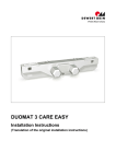
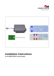
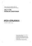
OKIMAT 6 Installation Instructions (Translation of the original installation instructions) OKIMAT 6 Foreword Foreword Revisions Version Date Changes (-) 11/10 First edition (a) 07/12 Second edition (b) 12/12 RoHS, Safety Instructions, Toggle Disclaimer and exclusion of liability DewertOkin is not responsible for damage resulting from: failure to observe these instructions, changes made to this product which have not been approved by DewertOkin, or the use of replacement parts which have not been approved or manufactured by DewertOkin. Address of manufacturer DewertOkin GmbH Weststraße 1 32278 Kirchlengern Germany Tel: +49 (0)5223/979-0 Fax: +49 (0)5223/75182 http://www.dewertokin.de [email protected] Creation of a complete operating instruction manual for the entire end product These instructions are only intended to be used by the end-product manufacturer. They should not be given to the operator of the end product. The factual information contained within may be used as a basis when creating the end-product manual. The warning and danger notices are best suited for use in the end product's manual. However it is not sufficient to simply follow these notices. You should also carry out an internal risk assessment for your end product. This can then be used as the basis for the safety notices in your manual. These installation instructions do not contain all information required to safely operate the end product. They only describe the installation and operation of the drive as partially completed machinery. The instructions are intended for the technicians responsible for manufacturing an end product and not for the operators of the end product. 68018(b) 3 Foreword OKIMAT 6 Notice for customers in EU nations German Inspection Authority (TÜV) testing label The construction of the OKIMAT 6 has been inspected by the German Inspection Authority (TÜV). The TÜV also monitors the production of the OKIMAT 6. The official German TÜV label certifies this construction inspection and production monitoring. Figure 1 4 The TÜV label 68018(b) OKIMAT 6 Table of Contents Table of Contents Foreword ............................................................................................................................ 3 Revisions ........................................................................................................................................................... 3 Disclaimer and exclusion of liability ............................................................................................................... 3 Address of manufacturer ................................................................................................................................. 3 Creation of a complete operating instruction manual for the entire end product ..................................... 3 Notice for customers in EU nations ................................................................................................................ 4 Table of Contents............................................................................................................... 5 1. General ................................................................................................................... 7 1.1 Configurations ................................................................................................................................... 7 1.2 About these installation instructions .............................................................................................. 7 1.3 Availability of this document ........................................................................................................... 7 1.4 Conventions used ............................................................................................................................. 8 2. Safety Notices ....................................................................................................... 9 2.1 Proper and intended usage .............................................................................................................. 9 2.2 Safety notices within the installation instruction and the operating instructions for the entire machine ...........................................................................................................................10 2.3 Selection and qualification of personnel ......................................................................................10 2.4 Notice on safety during operations ...............................................................................................11 2.5 Product identification .....................................................................................................................12 3. Possible combinations ....................................................................................... 13 4. Description .......................................................................................................... 14 4.1 Components ....................................................................................................................................14 5. Technical Specifications .................................................................................... 18 6. Installation ........................................................................................................... 20 6.1 Safety notices to observe during installation ..............................................................................20 6.2 Installation procedure .....................................................................................................................21 7. Notices for Operation ......................................................................................... 29 7.1 General notices ...............................................................................................................................29 7.2 Notice for operating with optional configuration .........................................................................32 8. Troubleshooting .................................................................................................. 33 68018(b) 5 Table of Contents OKIMAT 6 9. Maintenance ........................................................................................................ 34 9.1 Maintenance.....................................................................................................................................34 9.2 Cleaning and care ...........................................................................................................................35 10. Disposal ............................................................................................................... 36 Declaration of incorporation .........................................................................................................................37 EU Declaration of Conformity .......................................................................................................................38 6 68018(b) OKIMAT 6 General 1. General 1.1 Configurations The OKIMAT 6 double drive is run in several different configurations. The “Possible combinations” Chapter includes information about the different device combinations available. 1.2 About these installation instructions These installation instructions must be followed closely in order to install this drive successfully and safely in the end product. These instructions are not an operating manual for the end product. These instructions will help you to minimize danger, repair costs and down times. They will also help you to maximize the reliability and lifespan of the end product. CAUTION The notices in these instructions must be followed! Following the guidelines during installation and connection procedures will help to minimize: the risk of accident and injury, and damage to the drive system or the end product. These installation instructions have been written with due care and attention. However, unless otherwise required by law, we do not guarantee that the data, images and drawings are accurate or complete nor do we accept liability for their contents. We reserve the right to make unannounced technical changes in the course of our continual product improvement process! 1.3 Availability of this document As manufacturer of the end product, you are obligated to comply with Machinery Directive 2006/42/EC. This directive stipulates that the installation instructions must be kept on file for governmental inspection purposes. 68018(b) 7 General 1.4 OKIMAT 6 Conventions used Notices which do not relate to safety are indicated in these instructions with a triangle: Triangular notice symbol Safety notice explanations DANGER DANGER indicates a hazardous situation which, if not avoided, will result in serious injury or death. WARNING WARNING indicates a hazardous situation which, if not avoided, could result in serious injury or death. CAUTION CAUTION indicates a hazardous situation which, if not avoided, could result in minor or moderate injury. NOTICE NOTICE is used to address practices which are not related to personal injury but may result in damage to the product or surroundings. 8 68018(b) OKIMAT 6 Safety Notices 2. Safety Notices 2.1 Proper and intended usage The OKIMAT 6 drive is meant to be installed in beds. It provides motor adjustment capabilities for movable reclining bed parts. It should be used in conjunction with suitable fittings and mechanics: It can be used in the household (HOME). CAUTION This drive should only be used for the applications described above. Any other application is not permitted and can lead to accidents or damage to the unit. Such nonapproved applications will lead immediately to the expiration of all guarantee and warranty claims on the part of the end-product manufacturer against the manufacturer. Improper usage Be sure to follow the notices below concerning improper usage. You should include them in your product manual in order to inform the users of your end product. WARNING The OKIMAT 6 drive should not be used: with a medical product, or installed in a medical product. in any environment where combustible or explosive gases or vapours (e.g., anaesthesiology) may be present, in a moist environment, outdoors, in any application that will be cleaned with an automated washing system, for raising and lowering loads in industrial applications. CAUTION The OKIMAT 6 drive may not be operated: by small children, by frail or infirmed persons without supervision, or in the proximity of small children. CAUTION You should only use spare parts which have been manufactured or approved by DewertOkin. Only these parts will guarantee a sufficient level of safety. 68018(b) 9 Safety Notices OKIMAT 6 Option: battery-operated reset function CAUTION The battery-operated reset function is not a safety system and does not avert danger. DewertOkin does not guarantee that the drive will function in the event of a power outage. If the end-product manufacturer chooses to guarantee the functionality of the end product during a power outage, then the end-product manufacturer is responsible for arranging a mechanism to ensure this functionality. 2.2 Safety notices within the installation instruction and the operating instructions for the entire machine The manufacturer of the end product is only permitted to operate the OKIMAT 6 drive (by itself an incomplete machine) when the end product (for which the OKIMAT 6 drive is intended) is in compliance with all protective measures specified in the Machinery Directive 2006/42/EG, and when the manufacturer expressly declares the compliance of the end product. The manufacturer of the end product must create a manual for the users of that product. The safety notices in the end-product manual must be written based on the end product's risk assessment. 2.3 Selection and qualification of personnel This drive should only be installed into the end product by someone who has completed training in electronic motor assembly or has equivalent qualifications. You should only install this drive when you are qualified to do so. Otherwise, a properly qualified person should be found for this task. 10 68018(b) OKIMAT 6 2.4 Safety Notices Notice on safety during operations Basic safety rules must be followed in order to ensure that the end product can be continually operated in a safe manner. These rules must be observed while using the end product and while installing the drive. These rules and safety measures can be categorized as follows: Construction measures before the installation (refer to the "Ensuring operational reliability during installation" section in chapter "Installation") Safety fundamentals during the drive installation and during cable and wire routing (refer to the "Safety notices to observe during installation" section in the "Installation" Chapter). Using the drive in intermittent duty (refer to the "General notices" section in the "Notices for Operation" Chapter). Basic safety rules during operation (refer to the "Notices for Operation" Chapter). The creation of a manual for the end product which contains these and other safety rules. Creating a user's manual The manufacturer of the end product must create a manual for the users of that product. The safety notices in the end-product manual must be written based on the end product's risk assessment. 68018(b) 11 Safety Notices OKIMAT 6 2.5 Product identification 2.5.1 Ratings plate (type label) A ratings plate on each drive specifies the exact name and serial number of the drive. It also states the technical specifications valid for that particular drive. In particular, you will find the maximum pull force and the maximum push force here. The following illustration shows where the specifications are located on the drive's ratings plate. The ratings plate shown is an example; the specifications for your drive may differ from this illustration. Figure 2 Ratings plate example OKIMAT 6 Model name XXXXX Article number 230V ~ 50/60Hz Input voltage and frequency 50W Power level Intermittent Operation 2min/18min Intermittent operations: 2 minutes / 18 minutes max. force Push force Prod. Date Calendar week / year Serial-No. Serial number for your drive Use in dry rooms only! Protection class II IP20 Protection category Stroke Stroke (head / foot) Follow all special disposal instructions! 12 68018(b) OKIMAT 6 3. Possible combinations Possible combinations The OKIMAT 6 double drive can be combined for use with other single or double drives. The following basic combinations are possible: an OKIMAT 6 with a handset, an OKIMAT 6 as the main drive and a single drive used as a slave drive with a handset, an OKIMAT 6 as the main drive and two single drives used as slave drives with a handset. Systems can be customized by combining drives with the handset and control units as needed. The system components must be connected in a specific order. DewertOkin has separate system instruction manuals containing all information and instructions needed for these systems. Only a DewertOkin device should be used to control the drive since they have already been verified to work together. 68018(b) 13 Description 4. OKIMAT 6 Description The OKIMAT 6 drive is an electrically driven motor that is responsible for moving the end product in a linear direction. The head and foot sections of a bed can be adjusted depending on the drive options. The drive is controlled by means of a handset. The different drive models vary according to the: motor power, number of motors, also in the variations: attached power cord and detachable power cord model with optional reset function We reserve the right to make unannounced technical changes in the course of our continual product improvement process! The "Possible combinations" Chapter describes the different possible combinations of drives and handsets/hand-held remote controls. You can also ask your supplier or dealer for additional information. 4.1 Components The main components of the OKIMAT 6 drive are the motor and the adjustment motion mechanism. This mechanism is housed under the shutters. The shutters must be opened in order to mount the drive to the end product. The brackets fastened to the end product are then inserted into these openings. A B C B A F D E Figure 3 14 Main components of the OKIMAT 6 double drive (variant with attached power cord) A Shutters B Strain relief C Battery compartment with 9-V batteries D Symbol for head end of bed E (with attached power cord) F Symbol for foot end of bed 68018(b) OKIMAT 6 Description A B C B A F E D Figure 4 Main components of the OKIMAT 6 double drive (variant with detachable power cord) A Shutters B Strain relief C Shield cover for detachable power cord D Symbol for head end of bed E Batteries in battery compartment F Symbol for foot end of bed A A A Figure 5 Case options for the OKIMAT 6 double drive (Examples) A Sockets for the electrical connection The case variations of the motor's rear side depicted are only to be taken as examples. Other case options for the rear of the motor are possible. 68018(b) 15 Description 4.1.1 OKIMAT 6 Power supply connection to mains WARNING Please follow these operating instructions carefully. You could be injured by fire or electrical shock if you do not follow these assembly instructions. Variant with attached power cord The appropriate power cable is included, depending on the regional version (USA, continental Europe, the UK or Australia). WARNING Only use the proper power cable that is permitted in your country. Be sure to use the correct plug adapter, as described in Figure 6. A B C D Figure 6 E Power plug adapter, regional variants A Double drive OKIMAT 6 B Power plug (German version) C Power plug (USA version) D Power plug (Australian version) E Power plug (United Kingdom version) 16 68018(b) OKIMAT 6 Description Variant with detachable power cord The appropriate pluggable power cord is included, depending on the regional version (USA, continental Europe, the UK or Australia). WARNING Only use the proper power cable that is permitted in your country. Be sure to use the correct plug adapter, as described in Figure 7. A B C D Figure 7 68018(b) E F Power plug adapter, regional variants A Double drive OKIMAT 6 B Shield cover C Power plug (German version) D Power plug (USA version) E Power plug (Australian version) F Power plug (United Kingdom version) 17 Technical Specifications 5. OKIMAT 6 Technical Specifications Connection to mains power (AC) or Input voltage (DC) 100 V - 240 V AC, 50/60 Hz (refer to the ratings plate on the drive) Current consumption under rated load Max. 8.0 A DC Power output 50 W Fuse T 0.63 - T 3.15 A, depending on mains power connection (refer to the drive's ratings plate) Permitted push force Max. 8000 N (total on both sides) 1) 24 V DC (refer to the ratings plate on the drive) Mode of operation under max. rated load. Intermittent duty 2 min./18 min. Protection classification II Noise level ≤ 65 dB(A) Drive type Double drive Protection category IP20 Stroke 2) 87, 69 (standard), 53, 74 Colours Refer to sales brochure. Length x width x height 715 mm x 177 mm x 130 mm Axle gap distance 581 mm Weight Approx. 5 kg Option: battery-operated reset function Voltage One or two 9-V batteries (type 6LR61) , depending on version Ambient conditions for operation, storage and transport 18 Transport / storage temperature From -20 °C to +50 °C From -4 °F to +122 °F Operating temperature From +10 °C to +40 °C From +50 °F to +104 °F Relative humidity From 30% to 75% Air pressure From 800 hPa to 1060 hPa Altitude < 2000 m 1 Mode of operation: intermittent duty 2 min./18 min. This means that after the unit is operated with its rated load for up to two minutes it must then be paused for 18 minutes. The unit can malfunction if this pause is not observed! 2 Other stroke distances are available on request. 68018(b) OKIMAT 6 Technical Specifications 130 177 715 Figure 8 68018(b) Dimensions of OKIMAT 6 drive (in mm) 19 Installation OKIMAT 6 6. Installation 6.1 Safety notices to observe during installation Basic safety rules must be followed in order to ensure that the end product can be continually operated in a safe manner. These rules must be observed while using the end product and while installing the drive. 6.1.1 Ensuring operational reliability during installation The safety and reliability of the end product containing the DewertOkin drive can be ensured by using the proper construction methods described below. Avoiding fatigue fractures CAUTION Drives that are incorrectly installed can undergo fatigue fractures which then create a risk of injury. Install the drive in the end product so that it is properly aligned. This will help prevent shear stress. Do not position the drive at a slanted angle when installing it in the end product. A slanted angle between the intended direction of movement of the end product and the drive's direction will create shear stress and could lead to a fatigue fracture. Avoiding a pinching hazard CAUTION When designing your end product, you should take the drive adjustment movement into account with passive safety mechanisms and with the appropriate safety notices in your operating instructions. Installation methods for ensuring passive safety: Install the OKIMAT 6 drive so that none of the positions where shear and pinch hazards exist are accessible externally. When preparing safety notices for the operator, be sure that your operating instructions inform the user of these points. 20 68018(b) OKIMAT 6 Installation 6.2 Installation procedure 6.2.1 An example installation Before installing the drive, make sure that you are observing all of the safety notices found in the "Safety notices to observe during installation" section. A A B B C D D Figure 9 68018(b) Installing the double drive A Shutters B Fitting mounts C End product (bed) D Brackets 21 Installation OKIMAT 6 1 Move your product into a position where it is supporting no load. CAUTION Be sure to carry out work on the drive in a position so that no loads are bearing on it. Only in this way can you be sure to avoid any risks of crushing or injury. CAUTION Disconnect the batteries if you are using the battery-operated reset function. 2 Pull strongly on the shutters to the side (A). The slots (B) for the brackets (D) are uncovered. 3 Align the OKIMAT 6 next to your product. The slots for the head and foot sides must be properly aligned with the correct brackets on your product (refer to the symbols on the OKIMAT 6 as described in Figure 3). 4 Push the drive in so that the brackets (D) fit into the slots (B). 5 Close the shutters (A) on the drive by snapping them back in. The OKIMAT 6 is now securely attached to the end product. 6 Disconnect all additional components such as slave drives or handset from their sockets. 7 Connect the mains power plug. Follow the notice below when plugging the power plug into the power outlet: NOTICE There is a delay after the supply voltage is applied before the device actually turns on. Wait at least 15 seconds before commissioning. 22 68018(b) OKIMAT 6 6.2.2 Installation Electrical connection CAUTION Electrical components should be connected or disconnected only when the power supply cord is unplugged. NOTICE There is a delay after the supply voltage is applied before the device actually turns on. Wait at least 15 seconds before commissioning. Variant with attached power cord WARNING Only personnel with the following training are qualified to work on the attached power cord or to replace the power cord: someone who has completed training in electronic motor assembly or, someone with equivalent qualifications, or someone who has successfully completed the appropriate DewertOkin training program. You should only work on the attached power cord when you are qualified to do so. Otherwise, a properly qualified person should be found for this task. 68018(b) 23 Installation OKIMAT 6 Variant with detachable power cord The appropriate pluggable power cord is included, depending on the regional version (USA, continental Europe, the UK or Australia). The power socket is located behind the shield cover on the OKIMAT 6 drive. Be sure to use the correct pluggable power adapter, as described in Figure 10. WARNING Please follow these operating instructions carefully. You could be injured by fire or electrical shock if you do not follow these assembly instructions. A B C Figure 10 Power plug adapters, regional variants A Power socket B Power plug C Shield cover 24 68018(b) C OKIMAT 6 Installation The pluggable power cord should be attached to the power socket (A) located on the front of the OKIMAT 6 drive. WARNING Only use the proper power cable that is permitted in your country. Be sure to use the correct plug adapter, as described in Figure 7. CAUTION You should only connect and disconnect the cables when they are completely disconnected from any live current! 1 Unscrew the screws on the shield cover (C). 2 Pull the shield cover (C) away from the socket. 3 Plug the power plug from the power cord (B) into the socket (A). 4 Put the shield cover (C) back on. Tighten the screws back on the cover. Follow the notice below when plugging the power plug into the power outlet: NOTICE There is a delay after the supply voltage is applied before the device actually turns on. Wait at least 15 seconds before commissioning. 68018(b) 25 Installation OKIMAT 6 Option: battery-operated reset function Connecting the 9-V batteries A B C D C Figure11 D Connecting the 9-V batteries A Battery compartment B Battery clip, attached C 9-V battery (type 6LR61) D Battery clip, unattached CAUTION Connect the nine-volt batteries first when you would like to perform a battery-operated reset. The batteries may only be used to power the reset function one time. Take out the batteries and dispose of them properly after the reset function has been carried out. 26 68018(b) OKIMAT 6 Installation Routing the electrical cables When routing the cables, be sure that: the cables cannot get jammed, no mechanical load (such as pulling, pushing or bending) will be put on the cables, and the cables cannot be damaged in any way. Fasten all cables (especially the mains cable) to the end product using sufficient strain relief and kink prevention methods. Be sure that the design of the end product prevents the mains cable from coming into contact with the floor during transport. 68018(b) 27 Installation 6.2.3 OKIMAT 6 Dismantling CAUTION Work on electrical components should be conducted only when the mains power connection is unplugged. Certain details may change as a result of technical changes. 1 Move your product into a position where it is supporting no load. CAUTION Be sure to carry out work on the drive in a position so that no loads are bearing on it. Only in this way can you be sure to avoid any risks of crushing or injury. 2 Pull out the mains power plug! CAUTION Disconnect the batteries if you are using the battery-operated reset function. 3 Disconnect all additional components such as slave drives or handset from their sockets. NOTICE Be sure to support the drive's weight to prevent it falling. 4 Pull strongly on the shutters to the side (A). 5 Pull out the OKIMAT 6 far enough so that the brackets (D) are out of the slots (B). The OKIMAT 6 is now unattached and can be removed. 6 Push the shutters (A) back onto the OKIMAT 6 so that they are not lost during transportation. 28 68018(b) OKIMAT 6 7. Notices for Operation Notices for Operation The factual information contained within may be used when you are creating the end-product manual. The installation instructions do not contain all information required for the safe operation of the end product. They only describe the installation and operation of the drive as a partially assembled piece of machinery. CAUTION When creating the operating instructions, remember that the installation instructions are intended for qualified specialists and are not for typical users of the end product. 7.1 General notices Only a DewertOkin device should be used to control the drive since they have already been verified to work together. Delayed start-up Follow the notice below when plugging the power plug into the power outlet: NOTICE There is a delay after the supply voltage is applied before the device actually turns on. Wait at least 15 seconds before commissioning. Power-on time / intermittent operations The OKIMAT 6 drive has been designed for intermittent operations. Intermittent operation is an operational mode where the drive must pause after a specified maximum period of operation (poweron time). This protects the drive from overheating. In an extreme case, overheating can lead to a malfunction. The ratings plate on the drive specifies the maximum power-on time and the required pause intervals. Avoiding toggle operations You should avoid switching from one direction of travel to the opposite direction without first stopping the motor. – Make sure that you pause between motions! A pause (motor stop time) can be activated using the operating element or handset. NOTICE You should always avoid a quick change ("toggle") of directions. 68018(b) 29 Notices for Operation OKIMAT 6 Avoiding electrical risks WARNING Be sure that all live (current-carrying) parts of the drive system and power supply cannot be touched. In particular, be sure that unused power and controller connections are covered adequately. Shutting off the drive CAUTION Pull out the power plug in order to shut off the drive. The power plug must always be accessible during operations so that emergency shut-off is possible. Avoiding cable damage Be sure that your operating instructions inform the user about the possible cable risks. CAUTION The cables (particularly the mains cable) should not be run over. In order to prevent injuries or drive damage, no mechanical strain should be placed on the cables. 30 68018(b) OKIMAT 6 Notices for Operation Looping the handset cable through the strain relief mechanism B C A Figure 12 Looping the cable through the strain relief mechanism A Handset cable loop B Looped-in cable C Secured cable 1 Connect the plug from the handset to the handset socket on the OKIMAT 6. 2 Loop the handset cable through the strain relief catch and pull back gently on the loop as illustrated in Figure 12. 68018(b) 31 Notices for Operation OKIMAT 6 7.2 Notice for operating with optional configuration 7.2.1 Option: battery-operated reset function The battery-operated reset function allows the drive system to be operated during a power outage. One or two 9-V batteries can be used to power the OKIMAT 8 in the event of a power outage. The batteries should only be connected when a power cut occurs. The batteries are not connected by default since they have limited capacity. They can only be used to power the reset function once. The used batteries should then be replaced and properly disposed of. CAUTION The battery-operated reset function is not a safety system and does not avert danger. CAUTION Connect the nine-volt batteries first when you would like to perform a battery-operated reset. The batteries may only be used to power the reset function one time. Take out the batteries and dispose of them properly after the reset function has been carried out. If the end product is under a heavy load which prevents the reset function from operating, the strain or load on the end product must first be removed before a reset can be carried out. 7.2.2 Option: The mains cut-off mechanism The mains cut-off feature is only available with the attached power cord variants. The mains cut-off mechanism is responsible for isolating the drive automatically from the mains power supply when the drive is not moving. A switching component is used to isolate both poles of the power transformer from the mains power supply. The mains cut-off mechanism allows power to the drive only after a button has been pressed on the handset to trigger drive motion. Do not use the integrated mains cut-off if you already use an in-house mains cut-off system. WARNING The mains cut-off is not a "central command device" in the sense used by the DIN VDE regulations. You should first completely disconnect the voltage supply from the drive system before conducting any type of work on a DewertOkin product which features a mains cut-off. First pull out the power plug. This guarantees that the system is safely shut off in compliance with the German DIN VDE 0105 and BGV A3 regulations. 32 68018(b) OKIMAT 6 8. Troubleshooting Troubleshooting This chapter describes troubleshooting methods for fixing problems. If you experience an error that is not listed in this table, please contact your supplier. CAUTION Only qualified specialists who have received electrician training should carry out troubleshooting and repairs. Problem Possible cause Remedy The handset or drive system is not functioning. There is no mains supply voltage. Connect the mains power. The hand switch or drive system is defective. Please contact your supplier or sales agent. The drive is suddenly not capable of movement. Possibly the thermal circuit breaker on the transformer has been triggered or is defective. The drive system should be allowed to pause for 20 to 30 minutes. The thermal fuse on the transformer may have been triggered or may be defective. Please contact your supplier or sales agent. The unit's fuse may have been triggered or may be broken. Please contact your supplier or sales agent. There is no mains supply voltage. Connect the mains power. A lead-in connection has been interrupted (mains power, hand switch or auxiliary drive). Check the lead-in connections and re-seat the contacts if required. The batteries are empty. Check the batteries and replace if necessary. Battery is not connected. Connect the batteries. The battery-operated reset is not functioning. 68018(b) 33 Maintenance 9. OKIMAT 6 Maintenance You should only use spare parts which have been manufactured or approved by DewertOkin. Only these parts will guarantee a sufficient level of safety. 9.1 34 Maintenance Type of check Explanation Time interval Check the function and safety of the electrical system. A qualified electrician should carry out this inspection. (Refer to the "Electrical connection" section in the "Installation" chapter.) Periodic inspections can be carried out at intervals based on the risk assessment which you conduct for your end product. Look over the plug-in connections and electrical access points for signs of damage. Check that all electrical cables and connections are firmly seated and correctly positioned. At least every six months. Look over the cables for any signs of damage. Check the connecting cables for pinching or shearing. Also check the strain relief and kink protections mechanisms, in particular after any mechanical load. At least every six months. Periodic functional test of the end switches. Move the drive to the end positions in order to test the end switches. At least every six months. 68018(b) OKIMAT 6 9.2 Maintenance Cleaning and care The OKIMAT 6 drive was designed so that it would be easy to clean. NOTICE Never clean the drive in an automated washing system or with a high-pressure cleaner. Do not allow fluids to penetrate the drive. Damage to the system could result. 1 Always disconnect the mains power plug before you start to clean the drive! CAUTION Disconnect the batteries if you are using the battery-operated reset function. 2 Clean the OKIMAT 6 drive using a dry cloth. 3 Be sure that you do not damage the drive's connecting cable. NOTICE Do not use a cleanser that contains benzene, alcohol or similar solvents. 68018(b) 35 Disposal OKIMAT 6 10. Disposal The OKIMAT 6 drive consists of electronic components, cables and metal and plastic parts. You should observe all corresponding national and regional environmental regulations when disposing of the OKIMAT 6 drive. The disposal of the end product is regulated in Germany by Elektro-G, internationally by the EU Directive 2002/95/EC (RoHS, from 1 Jul. 2006) and Directive 2011/65/EU (RoHS, from 3 Jan. 2013), or by any applicable national laws and regulations. (The end product is not regulated by the EU Directive 2002/96/EC (WEEE) and its amendment EU Directive 2003/108/EC.) The OKIMAT 6 drive should not be disposed of with normal household waste! The disposal of the 9-V batteries is regulated in the EU by Battery Directive 2006/66/EC, in Germany by the BattG battery law of 25.6.2009, and internationally by any applicable national laws and regulations. The 9-V batteries should not be disposed of with normal household waste! 36 68018(b) Declaration of incorporation According to Appendix II of the EU Machinery Directive 2006/42/EC The manufacturer: DewertOkin GmbH Weststraße 1 32278 Kirchlengern Germany declares that the incomplete machine described below OKIMAT 6 complies with the following basic requirements of the Machinery Directive (2006/42/EC): Sections: 1.1.3; 1.3.3; 1.3.4; 1.3.7; 1.5.9; 1.5.10; 1.5.13; 1.6.3 1.5.1; 1.5.2; 1.5.5; 1.5.6; 1.5.7; 1.5.8; You may only operate this machine after you have confirmed that the end product (into which this drive will be installed) complies with the Machinery Directive 2006/42/EC. On request, the manufacturer is obliged to send the special documentation accompanying the partially completed machinery electronically to the appropriate national institution. The special technical documents corresponding to the machine have been created according to Appendix VII, part B. The following person is responsible for the technical documentation: Hartmut Klimm, Address cited above. Tel: 05223 979150 Kirchlengern, Germany on 15 December, 2012 Sascha Koltzenburg Head of R & D EU Declaration of Conformity In compliance with Appendix IV of the EU EMC Directive 2004/108/EC In compliance with Appendix III of the EU Low Voltage Directive 2006/95/EC In compliance with Appendix VI of the EU RoHS Directive 2011/65/EU The manufacturer: DewertOkin Antriebs- und Systemtechnik GmbH Weststraße 1 32278 Kirchlengern Germany declares that the following product OKIMAT 6 meets the requirements of the following EU directives: Electromagnetic Compatibility Directive 2004/108/EC Low Voltage Directive 2006/95/EC RoHS Directive 2011/65/EU of the European Parliament and of the Council of 8 June 2011 on the restriction of the use of certain hazardous substances in electrical and electronic equipment Applied standards: • EN 60335-1:2012 • EN 55014-1/A1:2009 • EN 55014-2/A2:2008 • EN 61000-3-2/A2:2009 • EN 61000-3-3:2008 This declaration of conformity is no longer valid if constructional changes are made which significantly change the control unit (i.e., which influence the technical specifications found in the instructions or the intended use)! Kirchlengern, Germany on 15 December, 2012 Sascha Koltzenburg Head of R & D DewertOkin GmbH Weststraße 1 32278 Kirchlengern, Germany Tel: +49 (0)5223/979-0 Fax: +49 (0)5223/75182 http://www.dewertokin.de [email protected] ID No.: 68018