1
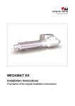
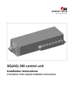
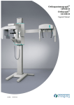
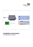
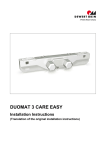
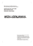
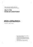
PD12 POWER SUPPLY Installation Instructions (Translation of the original installation instructions) PD12 POWER SUPPLY Foreword Foreword Revisions Version Date Changes (-) 12/09 First edition (a) 06/2010 Additional information (b) 10/2010 Technical Specifications (c) 02/11 temperature monitoring mechanism (d) 07/12 Second edition (e) 12/12 RoHS Disclaimer and exclusion of liability DewertOkin is not responsible for damage resulting from: failure to observe these instructions, changes made to this product which have not been approved by DewertOkin, or the use of replacement parts which have not been approved or manufactured by DewertOkin. Contact addresses DewertOkin GmbH Weststraße 1 32278 Kirchlengern Germany Tel: +49 (0)5223/979-0 Fax: +49 (0)5223/75182 http://www.dewertokin.de [email protected] Creation of a complete operating instruction manual for the entire end product These instructions are only intended to be used by the end-product manufacturer. They should not be given to the operator of the end product. The factual information contained within may be used as a basis when creating the end-product manual. The warning and danger notices are best suited for use in the end product's manual. However it is not sufficient to simply follow these notices. You should also carry out an internal risk assessment for your end product. This can then be used as the basis for the safety notices in your manual. Usage in medical products The PD12 POWER SUPPLY is not a medical product. As a manufacturer of a medical end product, you are obligated to establish compliance with EC directives and to ensure that other pertinent medical product regulations are maintained. 65696(e) 3 Table of Contents PD12 POWER SUPPLY Table of Contents Foreword 3 Revisions 3 Disclaimer and exclusion of liability 3 Contact addresses 3 Creation of a complete operating instruction manual for the entire end product 3 Usage in medical products 3 Table of Contents 4 1. General 5 1.1 About these installation instructions 5 1.2 Conventions used 5 2. Safety Notices 6 2.1 Proper and intended usage 6 2.2 Selection and qualification of personnel 7 2.3 Notice on safety during operations 7 2.4 Product labeling 8 3. Description of Power Supply 10 3.1 Components 10 4. Technical Specifications 14 4.1 PD12 POWER SUPPLY 14 5. Installation 17 5.1 Safety notices to observe during installation 17 5.2 Installation procedure 18 6. Notices for Operation 24 6.1 General notices 24 7. Troubleshooting 26 8. Maintenance 27 8.1 Maintenance 27 8.2 Cleaning and care 28 9. Disposal 29 Additional information 30 EU Declaration of Conformity 31 4 65696(e) PD12 POWER SUPPLY General 1. General 1.1 About these installation instructions These installation instructions must be observed in order to install this PD12 POWER SUPPLY successfully and safely in the end product. These instructions are not an operating manual for the end product. These instructions will help you to minimize danger, repair costs and down times. They will also help you to maximize the reliability and lifespan of the end product. CAUTION The notices in these instructions must be followed! Following the guidelines during installation and connection procedures will help to minimize: the risk of accident and injury, and damage to the PD12 POWER SUPPLY or to the end product. These installation instructions have been written with due care and attention. However, unless otherwise required by law, we do not guarantee that the data, images and drawings are accurate or complete nor do we accept liability for their contents. We reserve the right to make unannounced technical changes in the course of our continual product improvement process! 1.2 Conventions used Notices which do not relate to safety are indicated in these instructions with a symbol: Triangular notice symbol Explanations of warning notices DANGER DANGER indicates a hazardous situation which, if not avoided, will result in serious injury or death. WARNING WARNING indicates a hazardous situation which, if not avoided, could result in serious injury or death. CAUTION CAUTION indicates a hazardous situation which, if not avoided, could result in minor or moderate injury. NOTICE NOTICE is used to address practices which are not related to personal injury but may result in damage to the product or surroundings. 65696(e) 5 Safety Notices PD12 POWER SUPPLY 2. Safety Notices 2.1 Proper and intended usage The PD12 POWER SUPPLY is intended for use as a power supply for the appropriate DewertOkin drive systems. CAUTION This PD12 POWER SUPPLY should only be used for the applications described above. Any other application is not permitted and can lead to accidents or damage to the unit. Such non-approved applications will lead immediately to the expiration of all guarantee and warranty claims on the part of the end-product manufacturer against the manufacturer. 2.1.1 Improper usage Be sure to follow the notices below concerning improper usage. You should include them in your product manual in order to inform the users of your end product. WARNING The PD12 POWER SUPPLY may not be used: in any environment where combustible or explosive gases or vapors (e.g., anaesthesiology) may be present, in the proximity of open fires or other heat sources (such as furnaces, ovens or direct sunlight), as a power source for toys or games, in any application that will be cleaned with an automated washing system, in a moist environment, or outdoors. CAUTION The PD12 POWER SUPPLY may not be operated: by small children, by frail or infirmed persons without supervision, or in the proximity of small children. CAUTION You should only use spare parts or replacement parts which have been manufactured or approved by DewertOkin. Only these parts will guarantee a sufficient level of safety. 6 65696(e) Safety Notices PD12 POWER SUPPLY 2.2 Selection and qualification of personnel This PD12 POWER SUPPLY should only be installed into the end product by someone who has completed training in electronic motor assembly or has equivalent qualifications. You should only install this PD12 POWER SUPPLY when you are qualified to do so. Otherwise, a properly qualified person should be found for this task. 2.3 Notice on safety during operations Basic safety rules must be followed in order to ensure that the end product can be continually operated in a safe manner. These rules must be observed while using the end product and while installing the PD12 POWER SUPPLY. These rules and safety measures can be categorized as follows: Construction measures before the installation (refer to the "Ensuring operational reliability during installation" section in the chapter "Installation"). Safety fundamentals during the PD12 POWER SUPPLY installation and during cable and wire routing (refer to the "Electrical connection" section in the chapter "Installation") Basic safety rules during operation (refer to the "Notices for Operation" Chapter). The creation of a manual for the end product which contains these and other safety rules. 2.3.1 Creating a user's manual The manufacturer of the end product must create a manual for the users of that product. The safety notices in the end-product manual must be written based on the end product's risk assessment. 2.3.2 Electrical safety WARNING There is a danger of electrical shock! Before beginning installation, be sure to unplug the power plug from the PD12 POWER SUPPLY (floor unit) or unplug the PD12 POWER SUPPLY (power-outlet unit) from the power outlet! The PD12 POWER SUPPLY may not be opened! You must properly dispose of malfunctioning or broken units. 65696(e) 7 Safety Notices PD12 POWER SUPPLY 2.4 Product labeling 2.4.1 Ratings plate (type label) A ratings plate (or type label) on each PD12 POWER SUPPLY specifies the exact name and serial number of the unit. It also states the technical specifications valid for that particular PD12 POWER SUPPLY. The following illustration shows where the specifications are located on the ratings plate of the PD12 POWER SUPPLY. The ratings plate shown is an example; the specifications for your PD12 POWER SUPPLY may differ from this illustration. Figure 1 8 PD12 POWER SUPPLY ratings plate (example) 65696(e) Safety Notices PD12 POWER SUPPLY PD12 POWER SUPPLY Model name xxxxx ID No.: 100 V - 240 V ~ 50/60 Hz Input voltage and frequency max. 1.5A Current consumption Output: 29V 24V 52W 4A Output voltage and permitted max. output power during continuous operations Output voltage and permitted max. output power for intermittent operations: 2 minutes on / 18 minutes OFF Duty cycle: 2 min ON /18 min OFF Intermittent operations: 2 minutes on / 18 minutes OFF Prod.date Calendar week / year Serial No. PD12 POWER SUPPLY serial number IP20 Protection category Compliance Use in dry rooms only! Protection class II Short-circuit-proof safety transformer Follow all special disposal instructions! CLASS 2 Power supply in compliance with UL1310 EFFICIENCY LEVEL Efficiency class ta 40°C Max. permitted ambient temperature LSP plug 65696(e) 9 Description of Power Supply 3. PD12 POWER SUPPLY Description of Power Supply The PD12 POWER SUPPLY is an external power supply unit intended to supply power to drives and controllers from DewertOkin. The PD12 POWER SUPPLY can be connected to the mains by using either a power cord (for the floor unit) or a power plug adapter (for the pluggable unit). The PD12 POWER SUPPLY has a non-referenced (unearthed) circuit which is separated from the supply voltage by means of doubled reinforced insulation. A shield cover is used for connecting a drive or drive control unit to the PD12 POWER SUPPLY. We reserve the right to make unannounced technical changes in the course of our continual product improvement process! 3.1 Components The PD12 POWER SUPPLY consists of a housing with connection interfaces for the power supply and for the drive/controller cable. The connection for the drive/controller cable is fitted with a mechanism to guard against accidental unplugging. B A D C Figure 2 10 Components of the PD12 POWER SUPPLY (e.g., the floor unit) A PD12 POWER SUPPLY B Current fed optionally with the power cord (for the floor unit) or the power plug adapter (for the pluggable unit) C Plug from drive/control cable D Drive/control cable connection with mechanism to protect again pulling out 65696(e) Description of Power Supply PD12 POWER SUPPLY 3.1.1 Power supply connection to mains WARNING Please follow these operating instructions carefully. You could be injured by fire or electrical shock if you do not follow these assembly instructions. Option: Power cord The appropriate power cord is optionally included, depending on the regional version, in the USA, continental Europe, the UK or Australia. WARNING Only use the proper power cord that is permitted in your country. Be sure to use the correct plug adapter, as described in Figure 3. More information about the intended power supply cord can be found in the "Additional Information" section. A B C D E Figure 3 Power adapter, regional variants (for the floor unit) A PD12 POWER SUPPLY B Power cord (continental Europe version) C Power cord (USA version) D Power cord (Australian version) E Power cord (United Kingdom version) 65696(e) 11 Description of Power Supply PD12 POWER SUPPLY Option: Power adapter The following illustration shows the proper power adapters for regional usage. WARNING Only use the proper power adapter that is permitted in your country (Figure 4). A B C Figure 4 D E Power adapter, regional variants A PD12 POWER SUPPLY (pluggable unit) B Power adapter (continental Europe version) C Power adapter (USA version) D Power adapter (Australian version) E Power adapter (United Kingdom version) 12 65696(e) Description of Power Supply PD12 POWER SUPPLY 3.1.2 Electrical Output (options) The outlet for the drive system is available either as a DC plug or a LSP plug. A Figure 5 Electrical outlet variants A DC plug outlet 65696(e) B B LSP plug outlet 13 Technical Specifications PD12 POWER SUPPLY 4. Technical Specifications 4.1 PD12 POWER SUPPLY Power supply connection to mains 100 – 240 V AC 50/60 Hz Output voltage (under no load) max. 30 V DC Output voltage / output power Output: 29V Output voltage / output current 24 V Primary fuse 3.15 A Standby (no load) ≤ 0.5 W Degree of efficiency ≥ 0.87 Mode of operations 1 52W for continuous operations 4 A for intermittent operations: 2 min./18 min. Intermittent duty 2 min./18 min. Continuous operations Protection classification II Variants DC socket, LSP socket Protection category IP20 Colors Black Length of power cord 2 approx. 1200 mm (only for floor unit) Dimensions and weight Length x width x height (floor unit) approx. 184 mm x 60 mm x 50 mm Length x width x height (pluggable unit) approx. 154 mm x 60 mm x 84 mm Weight approx. 220 g Ambient conditions for operation, storage and transport 14 Ambient room temperature for storage and transport from -20 °C to +50 °C from -4 °F to +122 °F Ambient room temperature for operation from +10 °C to +40 °C from +50 °F to +104 °F Relative humidity from 30% to 75% Air pressure from 800 hPa to 1060 hPa Altitude < 2000 m 1) Mode of operation: intermittent duty 2 min./18 min. This means that after the unit is operated with its rated load for up to two minutes it must then be paused for 18 minutes. The unit can malfunction if this pause is not observed! 2) Versions with a power cord shorter than 2 meters are only suitable for outlets near the floor. 65696(e) Technical Specifications PD12 POWER SUPPLY 60 184 Figure 6 Dimensions of the PD12 POWER SUPPLY (floor unit), in mm, top view 50 Figure 7 Dimensions of the PD12 POWER SUPPLY (floor unit), in mm, side view 60 154 Figure 8 65696(e) Dimensions of the PD12 POWER SUPPLY (pluggable unit), in mm, top view 15 Technical Specifications PD12 POWER SUPPLY 84 Figure 9 16 Dimensions of the PD12 POWER SUPPLY (pluggable unit), in mm, side view 65696(e) PD12 POWER SUPPLY Installation 5. Installation 5.1 Safety notices to observe during installation Basic safety rules must be followed in order to ensure that the end product can be continually operated in a safe manner. These rules must be observed while using the end product and while installing the PD12 POWER SUPPLY. 5.1.1 Avoiding electrical faults The power supply cord (when available) is designed to be connected to an outlet near the floor. Be sure to consider the length of the power cord when designing the dimensions for your application in order to minimize the associated risks. 5.1.2 Ensuring operational reliability during installation The safety and reliability of the end product containing DewertOkin components can be ensured by using the proper construction methods described below. Overheating A temperature monitoring mechanism switches the MC10 control unit off if it overheats. CAUTION The PD12 POWER SUPPLY is equipped with a thermal fuse that triggers when the unit overheats. If the temperature monitoring mechanism has triggered, unplug the PD12 POWER SUPPLY from mains power and allow it to rest for 20 to 30 minutes. Then try it again. Contact your dealer or supplier if the control unit still does not function. Mechanical construction A shield covering on the sockets protects the drive connections from mechanical damage and accidental unplugging. 65696(e) 17 Installation 5.2 PD12 POWER SUPPLY Installation procedure Before installing the PD12 POWER SUPPLY, make sure that you are observing all of the safety notices found in the "Safety notices to observe during installation" section. 5.2.1 Installing the PD12 POWER SUPPLY The PD12 POWER SUPPLY is used as an accompanying device without any mounting or bolting down required. As an accompanying device, you should be sure that any dangers presented by the cables are described in your end-product operating manual (refer to section "Electrical connection"). CAUTION The mains power plug should be unplugged during the installation (for the floor unit). 5.2.2 Electrical connection CAUTION Electrical components should be connected or disconnected only when the power supply cord (for the floor unit) or the pluggable unit are unplugged. NOTICE There is a delay after the supply voltage is applied before the device actually turns on. Wait at least 15 seconds before commissioning. Routing the electrical cables When routing the cables, be sure that: the cables cannot get jammed, no mechanical load (such as pulling, pushing or bending) will be put on the cables, and the cables cannot be damaged in any way. Fasten all cables (especially the connecting cables) to the end product using sufficient kink prevention methods. Be sure that the design of the end product prevents the connecting cables from coming into contact with the floor during transport. 18 65696(e) PD12 POWER SUPPLY Installation Connecting the power adapter Push your power adapter (the adapter permitted for use in your region) into the adapter socket on the PD12 POWER SUPPLY. Insert until you hear the adapter snap in. Be sure to use the correct plug shape (Figure 4). WARNING Please follow these operating instructions carefully. You could be injured by fire or electrical shock if you do not follow these assembly instructions. WARNING Only use the proper power adapter that is permitted in your country (Figure 4). Figure 10 65696(e) Attaching a power adapter (e.g., the power adapter for use in the USA) 19 Installation PD12 POWER SUPPLY WARNING Insert the pluggable unit into the socket in an upright vertical position (as shown in Figure 11). 3 Figure 11 20 Inserting the pluggable unit into the socket (with example from the power adapter for use in the USA) 65696(e) PD12 POWER SUPPLY Installation Removing the power adapter Insert a slotted screwdriver into the plug's notched groove (as shown in Figure 12) and press back the tab gently. Pull out the power adapter while pressing back with the screwdriver. Figure 12 65696(e) Removing a power adapter (e.g., the power adapter for use in the USA) 21 Installation 5.2.3 PD12 POWER SUPPLY Connecting the drive/drive controller to the PD12 POWER SUPPLY The drive system connection depends on the connection methods offered by the drive or drive controller: For a drive with two available sockets, connect the PD12 POWER SUPPLY to the power supply socket. The other socket is intended for connecting a handset and labeled as such. If the drive only contains one possible connection, use a forked (Y) cable. The Y-cable merges the connections from the handset and the PD12 POWER SUPPLY and then forwards them to the drive. Figure 13 Opening the shield cover Use the appropriately labeled socket on the controller for the connection to the drive controller. 1 Unplug the power plug (for the floor unit) or the device from the outlet. CAUTION You should only connect and disconnect the cables when they are completely disconnected from any live current! 2 Open the shield cover (refer to Figure 13). 3 Connect the drive/drive controller plug or the plug from the Y-cable into the socket and then close the shield cover. Follow the notice below after plugging the power plug into the power outlet: NOTICE There is a delay after the supply voltage is applied before the device actually turns on. Wait at least 15 seconds before commissioning. 22 65696(e) PD12 POWER SUPPLY 5.2.4 Installation Disconnecting the PD12 POWER SUPPLY 1 Unplug the power plug (for the floor unit) or the device from the outlet. CAUTION You should only connect and disconnect the cables when they are completely disconnected from any live current! 2 Open the shield cover (refer to Figure 13). 3 Pull out the drive cable or the drive controller cable from the PD12 POWER SUPPLY. 65696(e) 23 Notices for Operation 6. PD12 POWER SUPPLY Notices for Operation The factual information contained within may be used when you are creating the end-product manual. The installation instructions do not contain all information required for the safe operation of the end product. They only describe the assembly and operation of the PD12 POWER SUPPLY as a partially assembled piece of machinery. CAUTION When creating the operating instructions, remember that the installation instructions are intended for qualified specialists and are not for typical users of the end product. 6.1 General notices Only drive and drive control units from DewertOkin should be connected to the PD12 POWER SUPPLY since they have already been verified to work together. Delayed start-up Follow the notice below after plugging the power plug into the power outlet: NOTICE There is a delay after the supply voltage is applied before the device actually turns on. Wait at least 15 seconds before commissioning. Avoiding electrical risks WARNING Be sure that all live (current-carrying) parts of the drive system and power supply cannot be touched. In particular, be sure that unused power and controller connections are covered adequately. The use of a power cord and optional power adapter WARNING Please follow these operating instructions carefully. You could be injured by fire or electrical shock if you do not follow these assembly instructions. WARNING Only use the proper power cord or power adapter that is permitted in your country. Be sure to use the correct plug adapter, as described in Figure 4. 24 65696(e) Notices for Operation PD12 POWER SUPPLY Minimizing dangers when the temperature monitoring mechanism has triggered CAUTION The PD12 POWER SUPPLY is equipped with a thermal fuse that triggers when the unit overheats. If the temperature monitoring mechanism has triggered, unplug the PD12 POWER SUPPLY from mains power and allow it to rest for 20 to 30 minutes. Then try it again. Contact your dealer or supplier if the control unit still does not function. Emergency shutoff of a connected drive or drive control unit CAUTION In an emergency, pull the mains plug (for the floor unit) or the PD12 POWER SUPPLY (for the pluggable unit) from the outlet in order to shutoff the connected drive or drive control unit. The power plug and the pluggable unit must always be accessible during operations so that it is possible to shut down the drive or drive control unit at any time. Avoiding cable damage Be sure that your operating instructions inform the user about the possible cable risks. CAUTION The cables (particularly the connecting cable) should not be run over. In order to prevent injuries or damage to the PD12 POWER SUPPLY, no mechanical strain should be placed on the cables. 65696(e) 25 Troubleshooting 7. PD12 POWER SUPPLY Troubleshooting This chapter describes troubleshooting methods for fixing problems. If you experience an error that is not listed in this table, please contact your supplier. CAUTION Only qualified specialists who have received electrician training should carry out troubleshooting and repairs. 26 Problem Possible cause Remedy The drive or drive control unit is not functioning. There is no mains supply voltage. Connect the mains power. The drive or drive control unit is defective. Please contact your supplier or sales agent. The drive is suddenly not capable of movement. The temperature monitoring mechanism or system protective element has been triggered. Remove source of overload (change or reduce the load weight). The unit's fuse may have been triggered. Please contact your supplier or sales agent. There is no mains supply voltage. Connect the mains power. A lead-in connection has been interrupted (mains power, auxiliary drive or handset). Check the lead-in connections and re-seat the contacts if required. Allow the system to rest for 20 to 30 minutes with the mains power unplugged. Contact your supplier or sales agent if you cannot fix the problem. 65696(e) PD12 POWER SUPPLY 8. Maintenance Maintenance CAUTION You should only use spare parts which have been manufactured or approved by DewertOkin. Only these parts will guarantee a sufficient level of safety. 8.1 65696(e) Maintenance Type of check Explanation Time interval Check the function and safety of the electrical system. A qualified electrician should carry out this inspection. (Refer to the "Electrical connection" section in the "Installation" chapter.) Periodic inspections can be carried out at intervals based on the risk assessment which you conduct for your end product. Look over the housing periodically for any signs of damage. Check the housing for breaks or cracks. At least every six months. Look over the plug-in connections and electrical access points for signs of damage. Check that all electrical cables and connections are firmly seated and correctly positioned. At least every six months. Look over the cables for any signs of damage. Check the connecting cables for pinching or shearing. Also check the strain relief and kink protection mechanisms, in particular after any mechanical load. At least every six months. 27 Maintenance 8.2 PD12 POWER SUPPLY Cleaning and care The PD12 POWER SUPPLY was designed so that it would be easy to clean. The smooth surfaces can be conveniently cleaned. NOTICE Never clean the PD12 POWER SUPPLY in an automated washing system or with a high-pressure cleaner. Do not allow fluids to penetrate into the unit. Damage to the system could result. Do not use a cleanser that contains benzene, alcohol or similar solvents. 1 Before beginning cleaning, be sure to unplug the mains plug (for the floor unit) or the PD12 POWER SUPPLY from the outlet! 2 Clean the PD12 POWER SUPPLY using a dry cloth 3 Be sure that you do not damage the connecting cables during the cleaning. 28 65696(e) PD12 POWER SUPPLY 9. Disposal Disposal The PD12 POWER SUPPLY consists of electronic components, cables and metal and plastic parts. You should observe all corresponding national and regional environmental regulations when disposing of the PD12 POWER SUPPLY. The disposal of the end product is regulated in Germany by Elektro-G, internationally by the EU Directive 2002/95/EC (RoHS, from 1 Jul. 2006) and Directive 2011/65/EU (RoHS, from 3 Jan. 2013), or by any applicable national laws and regulations. (The end product is not regulated by the EU Directive 2002/96/EC (WEEE) and its amendment EU Directive 2003/108/EC.) This PD12 POWER SUPPLY should not be disposed of with normal household waste! 65696(e) 29 Additional information PD12 POWER SUPPLY Intended cord type in the USA and Canada: Power supply cord (see UL 1310) Flexible cord type Conductor size Number of conductors SP-2, SPE-2, SPT-2, SV, SVE, SVT 18 AWG S, SE, SO, SP-3, SPT-3, ST, STO, SJ, SJE, SJO, SJT, SJTO 18 AWG Cord length Minimum Maximum 2 0.91 m (3 feet) 3 m (10 feet) 2 0.91 m (3 feet) Not specified Intended cord type outside of the USA and Canada: Power supply cord (see IEC/EN 61558-1) Flexible cord type H05VV-F, H05VVH2-F, H05RR-F Conductor size Number of conductors 0.75 mm² 2 Cord length Minimum Maximum 2m 4m EU Declaration of Conformity In compliance with Appendix IV of the EU EMC Directive 2004/108/EC In compliance with Appendix III of the EU Low Voltage Directive 2006/95/EC In compliance with Appendix VI of the EU RoHS Directive 2011/65/EU The manufacturer: DewertOkin GmbH Weststraße 1 32278 Kirchlengern, Germany Germany declares that the following product PD12 POWER SUPPLY meets the requirements of the following EU directives: Electromagnetic Compatibility Directive 2004/108/EC Low Voltage Directive 2006/95/EC RoHS Directive 2011/65/EU of the European Parliament and of the Council of 8 June 2011 on the restriction of the use of certain hazardous substances in electrical and electronic equipment Applied standards: • EN 60335-1:2012 • EN 55014-1/A1:2009 • EN 55014-2/A2:2008 • EN 61000-3-2/A2:2009 • EN 61000-3-3:2008 • EN 61558-2-6:2009 • EN 61558-1/A1:2009 • EN 62233:2008 This declaration of conformity is no longer valid if constructional changes are made which significantly change the control unit (i.e., which influence the technical specifications found in the instructions or the intended use)! Kirchlengern, Germany on 15 December, 2012 Sascha Koltzenburg Head of R & D DewertOkin GmbH Weststraße 1 32278 Kirchlengern, Germany Tel: +49 (0)5223/979-0 Fax: +49 (0)5223/75182 http://www.dewertokin.de [email protected] ID No.: 65696