1
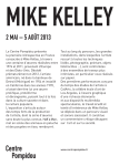
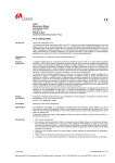
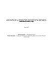
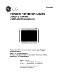
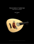
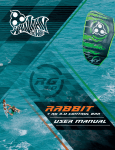
Kite Designing and Kite making
1 of 24
http://kitesurfingschool.org/kite.htm
Kites, Buggies, Gear
HQ, Flexifoil, Peter Lynn, Mystic Life is better when it blows!
www.coastalwindsports.com
Kiteworld
The Online Kite store Kites, Kitebuggys, Kitesurfing
Dan Tranh & Dan Bau
Beautiful, exotic musical
instruments
DanTranh.com
www.kiteworld.co.uk
Windsurfing holidays
The beginners paradise Lake Garda Stickl Sportcamp &
Hotel since 1976
www.stickl.com
become a kiteboarder
learn kiteboarding in paradise with our proffesional team
Kitesurfing Search
Contents
Introduction
Home
FAQ
Myths
Equipment
Tuning
Safety
www.cuttlebone.net
Kite Designing, Kite Making
(Last Update: 05/07/2007 08:10:03)
In the early days, kite designing and making was an art exclusive to a small group of people wh o are gifted with
tremendous amount of aerodynamic knowledge, skilful in drafting, sewing and other handy works.
Techniques
Basic How-To
Jumping
Landing
Tricks
Light Air
Heavy Air
Speed
Finless
Tips
Log
Rules
Snow, Land, Boat & Night
KiteSnowboarding
KiteSkiing
KiteTelemarking
KiteSnowblading
KiteSkating
KiteLandBoarding
KiteBoating
Night Kiting
Buy, Design, Build & Repair
Used Equipment
Kite Designing, Making
Flat LEI (Bow Kites)
Board Building
Bar Making
Bladder Repair
Not anymore! With the help of modern kite design fundamentals, kite design software, database of airfoils,
sample kite designs, almost all kiters can make their own kite. Let's take a look at all those elements one by one
and see where we are with the art of kite making:
1.
2.
3.
4.
5.
6.
7.
8.
9.
10.
11.
12.
Kite Design Fundamentals
Flat LEI
Airfoil Database
Kite Design Software
Kite Design Samples
Kitesurfingschool.org Kite Design Sample Database
Kite Sewing Methodologies
Kite Making Discussion Groups
Pseudo Surfplan User Manual
LEI Sphere Theory
Bruno's Post on Kitesurf Group
Peter Lynn's Myths on Kitesurf Group
Teaching & Schools
Teaching
KTM Teaching
Methodology
School Lists
More Info
Search
Discussion
RSS Feed
Blogs
Glossary
Historic Gallery
Kite Design Fundamentals
Kites, especially sled kites, are very complex aerodynamic devices (as complex as if not more t han airplane
wings). If you are not familiar with airfoil, profile, wing and the associated terminology, read
http://www.dreesecode.com/other/aflprimer.pdf or some other airfoil primer introduction before continuing. Now
let's take a quick look specifically at those that applies for kites
Forces and Torques on a Kite
[Read this now if you are ready; otherwise, just read the summary or you can skip the whole thing now and read
it later]
6/13/2007 4:00 PM
Kite Designing and Kite making
2 of 24
Links
Feedback
Contact Us
Latest Modifications
http://kitesurfingschool.org/kite.htm
Like an airplane wing, a kite can fly due to various forces acting on it. The main differences are that an airplane
has thrust while a kite has line tension and an airplane is balanced by its weight around its C enter of Gravity
(CoG) while a kite is balanced by its effective tow points (which can be adjusted automatically by the kite or
manually by the kiter) and its weight at CoG. Let take a quick look at all the force and torqu e players:
Wind Generated Forces:
Lift: This is the vertical force upward perpendicular to the wind that provide lift to the kite. T he Lift
of the kite is proportional to the Lift Coefficient (Cl) of the airfoil which varies dependent on the
angle of attack (AoA) of the kite. From 0 to around 20 degrees (most dominant AoA range for
kiting), Cl increases as AoA increases. After the peak in around 15 to 20 degrees, Cl will
decrease. More info about Lift can be found at
http://www.grc.nasa.gov/WWW/Wright/airplane/lifteq.html .
Drag: (or profile Drag) is the horizontal force in the same direction as the wind that drags the ki te
rearward. Similar to Lift, the Drag force is proportional to the Drag Coefficient (Cd) which v aries
dependent on the AoA. Cd normally increases as AoA increases. More info about drag can be
found at http://www.grc.nasa.gov/WWW/Wright/airplane/drageq.html .
Lift/Drag (L/D) ratio: The L/D ratio shows how Lift changes as compare to Drag. The faster Lift
increases compare to Drag or the slower Lift decreases compare to Drag, the higher the L/D rati o.
From 0 to around 20 degrees (the most dominant AoA range for kiting), the L/D ratio is inverse
proportional to AoA: low AoA means high L/D and high AoA means low L/D.
Induced Drag: Induced Drag is the drag occurred when a physical wing or kite is flying. The total
Drag of the kite is sum of the profile Drag and the induced Drag. Induced Drag is proportional to
square of Cl (Lift Coefficient), inverse proportional to the Aspect Ratio (AR) of the kite and also
inverse proportional to the shape of the kite (Induced Drag is minimum for an elliptical planfo rm).
Moment (or Torque): this is the rotational force that either flips the kite over its nose (for tradit ional
airfoil, negative moment) or over its tail (for reflex airfoil, positive moment). The point al ong the
chord where Moment force is constant for all AoAs is called the Aerodynamic Center. History an d
experiments have shown that for most subsonic airfoils, the "quarter-chord" point at 25% of cho rd
from the leading edge has a fairly constant Moment (for AoAs from -5 to 20 degrees, the range o f
AoA most important for airplanes and kites) and most if not ALL modern data are measured using
the quarter-chord point as the AC. Moment is proportional to Moment Coefficient (Cm) and the
chord of the airfoil. More info about AC and Moment can be found at
http://www.grc.nasa.gov/WWW/Wright/airplane/ac.html and
http://www.grc.nasa.gov/WWW/Wright/airplane/cp.html .
There are TWO MATHEMATICAL MODELS used by designers to consider how the Lift, Drag
forces and the Moment act on the airplane or kite:
The AC and Moment model: In this model, the Lift, Drag forces and the Moment are
considered acting at the AC. The Moment, if negative will flip the kite over the nose around
the AC (traditional airfoil) and if positive will flip the kite over the tail around the AC (r eflex
airfoil).
The Center of Pressure (CoP) model: In this model, there is only Lift and Drag forces acting
at a single point on the chord line called the Center of Pressure (CoP). Since the CoP is not
necessary at the same location as the AC, the Lift and Drag forces (the sum of Lift and Drag
forces component that are perpendicular to the chord line; let's call it Fcop) will generate a
torque around the AC. Since the torque around the AC is constant, the CoP is close to the
AC when the force Fcop is high (large AoA), and the CoP is far from the AC when the force is
small (small AoA).
For traditional airfoil, the Moment is negative, therefore, the CoP moves along the rearward
side of AC (from 25% of chord to the rear).
For reflex airfoil, the Moment is positive, therefore the CoP moves along the frontward side of
AC (from 25% of chord to front).
Since the Moment is constant, it moves either along the front side or rear side of the AC
(dependent on the airfoil type) and will NEVER cross the AC.
Some CoP chart can be found at
http://naca.larc.nasa.gov/reports/1921/naca-report-93/naca-report-93.pdf .
Both the AC/Moment and the CoP mathematical models are useful and can be used in different
situations in the wing and kite design process. For some reasons, airplane designers are more
comfortable with the AC/Moment model (this is one of the main reasons why airplanes have
tail-wing to counter balance the Moment of the main wing) and kite designers are more comfortab le
with the CoP model (it is easier to deal with 1 force than with a force and a moment). In any event,
from these 2 models, one can approximately determine the position of the CoP mathematically as:
CoP position = AC - Cm/Cl
The exact equation is:
CoP position = AC - Cm/( Cl(Cos(AoA) + Cd(sin(AoA) )
So at any AoA, once Cl, Cd and Cm are known (normally measured in the wind tunnel at
quarter-chord point), we can determine the position of CoP at 0.25 - Cm/Cl of chord from the
leading edge. Please note the minus sign, if Cm is negative, the CoP is on the rear side of the
quarter-chord point (traditional airfoils normally used in LEI) and if Cm is positive, the CoP is on the
front side of the quarter-chord point (reflex airfoil normally used in Arc).
Why is CoP so important to a kite designer? CoP is important to the kite designer because it is the
location of the kite that the effective tow point has to be at or the bridle system has to support
during the flight of the kite. Since CoP of the kite is changing during flight, the effective tow point of
6/13/2007 4:00 PM
Kite Designing and Kite making
3 of 24
http://kitesurfingschool.org/kite.htm
the kite has to change accordingly (either support statically via bridle line tensions, change
automatically via a spherical shape, or change manually via the back and front lines of a spherical
shape).
Gravity Force:
The kite weight is centered at its Center of Gravity. The Lift of the kite must be larger than the
weight of the kite for it to fly. A kite is an unbalanced device and won't be able to fly by itself unless:
1.
2.
It has a "thrusters system" that pushes it forward to counter balance the Drag
force and some mechanism to counter balance the Moment (e.g., tail plane. For
airplane without tail plane, it needs to use reflex profile and place its CoG in front
of the main wing). This is the simple model for an air plane.
Has a tether line placed at an appropriate location to counter-react the Drag
force and the Moment. This is the model for a kite.
Line Tension:
The line tension is the main force component of the kite that act similar to the thrust force o f an
airplane. While the thrust force is an active force, Line tension is a static force. The effe ctive tow
point is a location along the chord line that the line tension acts on. A tow point can be a s ingle
fixed tow point, a bridled tow point, a dynamic sled tow point or a full control sled tow point.
Single fixed tow point: the tether line is connected directly to the kite. This is almost neve r
used in a traction kite (there is however a kite patent on fixed tow point at
http://v3.espacenet.com/textdoc?DB=EPODOC&IDX=WO0158755&F=0&RPN=WO9005663 )
Bridled tow point: the effective tow point is determine by a bridle system consisting of multip le
connections to the kite. While the built-in effective tow point is the most optimum location f or
a bridle system to counter-react the lift from the kite, the bridle system can accommodate
some variation around the built-in effective tow point during flight by automatically adjusting
the tension on various parts of the bridle lines.
Dynamic sled tow point: Using a spherical form, a sled intrinsically has a dynamic tow point
configuration for the kite (more for the central part, less for the wingtip) where the effectiv e
tow point can varies quite a range dynamically while the kite is flying (this is the case of an
original 2 line LEI as described in Bruno's LEI patent).
Full control sled tow point: Using a spherical form and a system of front lines and back lines ,
a 4 line sled has a dynamic fully controllable configuration where the effective tow point are
dynamically readjusted during the fly and also be fully manipulated by the kiter (this is the
case of a 4 line sled, LEI or Arc).
When a kite is balanced on the sky, all the forces and torques acting on it must be equal. Thi s
means:
1.
2.
3.
The Lift of the kite has to be larger than the weight of the kite; the left over Lift
will create line tension to generate pull and also "thrust" ( this thrust force T is
equal to (L-W)*Tan(AoA) when the kite is fully balance) due to the inclination of
the line to move the kite forward (only if this "thrust" is larger than the sum of
Profile Drag and Induced Drag).
Using the AC and Moment model, the line tension and the weight of the kite has
to balance the Moment of the kite about its AC or quarter-chord point. Normally
when a kite is flying (especially a traction kite), lift is much higher than weight
and the Moment about the AC is higher than the torque created by the weight of
the kite. The effective tow point should be rearward of the AC (25% of chord) for
traditional airfoil (which has negative Moment) and frontward of the AC for reflex
airfoil (which has positive Moment).
Using the CoP model, the difference of the Lift force at CoP and the kite weight
at CoG is a force L1 slightly less than Lift and very close to CoP (since Lift is
normally much larger than Weight; otherwise, we won't feel any force on the
line). Let's call this spot CoPg. If CoP is frontward of CoG, CoPg is slightly
rearward of CoP and if CoP is rearward of CoG, CoPg is frontward of CoP.
The kite is balance longitudinally when the effective tow point is around the
CoPg. For a bridle system, the CoPg should be within the range supported by
the bridle system. For a dynamic sled tow point system (2 line LEI), the kite will
rotate and change the effective tow point to match that of the CoPg (the kite line
will point straight to the CoPg). For a full control sled, the kite can readjust the
tow point automatically or the kiter can do it manually. While the kite is flying the
CoP is changing and the kite balances its tow point correspondingly to keep
longitudinal balance.
Balancing the tow point will change the kite AoA to the wind (more drastically
6/13/2007 4:00 PM
Kite Designing and Kite making
4 of 24
http://kitesurfingschool.org/kite.htm
with sled) depending on the shape of the kite. For example, for a typical AR 5
sled (with a kite angle of 50 degrees - read the Sphere theory for kite angle),
decrease the tow point 1% of chord is equal to increase the AoA 0.5 degree and
vice and versa). So for a sled using a traditional airfoil (LEI), during the flight
path, the wind direction changes and the AoA increases, the CoP will decrease
and the the kite will rotate itself to increase the AoA further. In this case, the kite
amplifies the AoA increase so the kite designer has to make sure that at all
places along its path, the kite will not luff nor stall due to this additional
automatic adjustment from the kite.
This phenomenon from sled kite using traditional airfoil (for LEI only as Arc uses
mostly reflex airfoil due to concern about wingtip or shoulder collapsing) makes it
an excellent performer as it accelerates the Lift during the growth phase (AoA
from 0 to around 20) and decelerates the Lift loss during the decline phase (AoA
from 20 and above)
For AoA from minus 5 to 20:
AoA increases during flight path -> CoP moves frontward -> Tow point follows
CoP frontward -> AoA further increases -> Even more Lift
For AoA from 20 and above:
AoA increases during flight path -> CoP moves rearward -> Tow point follows
CoP rearward -> AoA decreases -> Hang on to the Lift as long as possible.
This effect is called "Sled Boosting" effect and is the reason why many kiters
feel that they can jump easier and higher with LEI and LEI won the battle over
foil in the early days of kitesurfing.
For sled using reflex airfoil (such as Arc or LEI using reflex airfoil), the " Sled
Boosting" effect is reverse, which means that it would protect the kite from
exposing itself to very large or very small AoA. This mean that for Arc, the kite
will try to retain within a range AoA with excellent L/D ratio. So this type of kite
will be fast and leverage power from speed instead of lift like the case of LEI.
Furthermore, with a 4 line sled, the kiter can adjust the effective tow point
(adjusting the length of the front line and back line) when the AoA become too
little or too much. This is what depower really mean for a 4 line sled. At any
CoP position, a kiter can adjust the front line and back line such that the kite will
fly a certain degrees of AoA smaller or larger than the case of a 2 line sled kite.
The kite will fly properly once it reaches longitudinal balance and will continue to
adjust its longitudinal balance automatically (or the kiter can help manually)
during the flight.
4.
The kite will stop flying when its "thrust" force is equal the sum of all the drag
forces (Profile Drag and Induced Drag). So the wind-window and the AoA of the
kite at the wind window is determined by the kite itself (the airfoil
characteristics). The built-in effective tow point should be selected accordingly
to be as close as the wind window CoP as possible (via bridle setting for bridle
kite and via Profile Attachment Points for sled kite).
Summary:
1.
2.
3.
4.
A kite has Lift and Drag similar to an airplane.
CoP of a kite varies dependent on AoA. CoP is closer to AC (25% of chord from leading edge) for large
AoA and farther from AC for small AoA. For traditional foils, CoP is normally around 27% (AoA around 20
degrees) to 55% (AoA around 0) of chord from leading edge. For reflex airfoil (Arc), the CoP i s normally
frontward from 0 to 25% of chord.
The tow point of the kite should either statically (bridled kite) or dynamically (sled kites) s upport the range
of variation of the CoP when the kite is flying across the wind window. In the case of sled kite it is
automatic. By following the CoP automatically, a sled kite using a traditional airfoil (such a s LEI)
"amplifies" the acceleration of Lift and sustain the peak. This "Sled Boosting" effect is one of the main
reason why a LEI kite jumps higher and easier to jump.
The Lift, Weight and Drag of the kite determine the wind window and the AoA of the kite at the wind
window.
Important Kite Design Parameters
The most easy to manipulate and highly visible kite parameters are Aspect Ratio (AR), Airfoil P rofile and built-in
Angle of Attack (AoA) of the kite:
Aspect Ratio
6/13/2007 4:00 PM
Kite Designing and Kite making
5 of 24
http://kitesurfingschool.org/kite.htm
Aspect Ratio is approximately Span/Chord of the kite or more exactly Span*Span/Area. Since AR
determines the shape of the kite it is the most visible kite design parameter that the user wil l see. Higher
AR kites have less induced drag (upwash and tip vortex effects) than Lower AR kites of the sam e
characteristics. Induced drag is inverse proportional to AR. So when stationary at the wind window, a low
AR kite can generate the same amount of pull as a higher AR kite (of the same characteristics) but as soon
as we need to move the kite for more power (for jumping or underpowered situation), a higher AR kite can
accelerate faster therefore get more power sooner than a low AR kite. As a rule of thumb, a hi gher AR kite
has a larger Power Window (the difference between min power and max power) and a lower AR kite has a
smaller Power Window. Following are the recommended AR ranges:
Kite Type
Very Low AR Low AR Moderate AR High AR Very High AR
Foil
2.5-
3
4
5
5.5+
Inflatable / Arc
3-
4
5
6
7+
Inflatable and Arc have spherical shape, a natural stable form, therefore their ARs are normall y higher than
foil's.
Airfoil Profile
Airfoil has lift but also drag. A profile with the highest lift when stationary will give the strongest pull when
stationary at the wind window (AoA around 5 degrees). A profile with highest lift/drag ratio will accelerate
faster and will generate strongest pull when flying across the power zone. A high lift airfoil is sometime
labelled a "tractor" airfoil as it will pull like a tractor at the wind window. A high lift/drag airfoil is labelled a
"speed" airfoil as it flies very fast across the power zone and generate tremendous amount of p ull while
doing so. A speed airfoil may generate a lot of pull at the wind window but may not be necessary as much
as a tractor airfoil. The following table show the recommended lift and lift/drag ratio ranges :
Very Low
Low
Moderate
High
Very High
Lift Coefficient
0.5(at AoA = 5)
0.7
0.9
1
1.1+ (Tractor)
40-
50
70
90
110+ (Speed)
Lift/Drag
Please note that these Lift/Drag ratios are the calculated ratio and not included Induced Drag. In reality,
the "real world" L/D ratios are reduced by a factor of 6 or 7.
It's best to use an airfoil design program (such as DesignFoil at http://www.dreesecode.com/ - if you want
to buy the software after using the demo version, you can get an excellent educational discount by
mentioned that you are a reader of Kitesurfingschool.org) to design, analyze and select the air foil profile to
use for the kite (for kiting purposes, the Reynolds number is around 1,000,000 to 2,000,000).
Some kite designers being shy from the complexity of airfoil design and analysis, uses the rule of thumb
method of changing the profile thickness/camber for changing the lift and lift/drag characteri stics of a
profile. This method is not accurate but maybe acceptable for kites. As a general rule of thumb, increase
the profile thickness/camber to increase lift at wind window and decrease a profile thickness/c amber to
increase the speed of the kite. The following table show the range of profile thickness/camber used for
most kites:
Foil and Arc
Thin Profile (Speed): 14% or less
Moderate Profile: 15%
Thick Profile: 16%
Thicker Profile: 17%
Thickest Profile (Tractor): 18% or more
Inflatable
Thin Profile (Speed): 8% - 9%
Moderate Profile: 10%
Thick Profile: 11%
Thicker Profile: 12%
Thickest Profile (Tractor): 13% - 14%
Built-in AoA
A kite get more lift with a higher Angle of Attacked (AoA) to the wind (more surface projected to the wind
and also from 0 to 16 degrees of AoA, the Lift Coefficient of an airfoil normally increase to a n optimum
value). Each kite has a "neutral" built-in AoA for the center of the kite and the wing tip whe n it is at the
wind window straight over-head (with front lines and back lines of equal length). The range of the built-in
AoA is normally from 0 to 5 degrees. Note that the wind-window angle is around 85 degrees such that the
in-flight AoA of the center profile at the wind window is the sum of the built-in AoA and 5 degrees (or 90 85). Note that changing the built-in AoA of the kite may also change the wind window angle such that the
two will "amplify" each other to have a "double AoA" effect. E.g., changing the built-in AoA f rom 2 to 0 may
make the wind window angle change from 85 to 86; therefore the in-flight AoA of the kite at wind window is
now 4 degrees instead of 7.
It is interesting to read Peter Lynn's Myth 1 and 2 in which he stated that the Lift or pull of the kite at wind
window is proportional to the AoA of the kite and the L/D of a kite is inverse proportional to the AoA of a
kite (AoA here means AoA within the "dominant AoA" range of 0 to around 20 degrees which is dir ectly
influenced by the built-in AoA of the kite).
6/13/2007 4:00 PM
Kite Designing and Kite making
6 of 24
http://kitesurfingschool.org/kite.htm
A kite with a lower built-in center AoA has a larger wind window but can over-fly & luff easily and
does not pull much at wind window (a Speed kite should have a lower built-in AoA around 0
degrees). These type of kites must have instantaneous AoA control for the kiter to prevent luff ing
and also for the kiter to "sheet-in" to get more power at wind window if needed.
A kite with higher built-in center AoA has a smaller wind window but generate more pull at wind
window and hard to luff (a Tractor kite may have higher built-in AoA around 3 to 5 degrees for more
pull at wind window)
An all-around kite may have a built-in AoA of 2 to 3 degrees.
Due to the upwash and the wing vortex phenomena, the built-in wingtip AoA of a kite can be 1 or 2
degrees higher than the center AoA. The upwash effect reduces the AoA of the wingtip a bit so add
1 or 2 degrees to the wingtip AoA to counter balance that effect.
For inflatable and Arc, due to their geometry, the wingtip AoA varies much different than the c enter
AoA and therefore the built-in wingtip AoA can be designed independent from the center AoA and
the designer should add 1 or 2 degrees to the desired built-in AoA to counter balance the up-wa sh
and the tip vortex effects.
Very Low AoA
Low AoA
Moderate AoA
High AoA
Very High AoA
Range (in
degrees)
0-
1
2-3
4
5+
Kite Type
Racing
Speed
All-around
Wave
Tractor (Wake
Style)
The following tables provide the summary of the AR, Airfoil, AoA parameters:
Low
High
AR
Small POWER Window
Large POWER Window
Lift (at wind window)
Weak pull at wind window
Strong Pull at Wind Window
Lift/Drag Ratio
Slow
Fast
Built-in AoA
Large WIND Window
Small AoA at wind window (less
pull)
Luff Easily
Faster
Small WIND Window
High AoA at wind window (more pull)
Hard to Luff
Slower
and their uses in different types of kite:
Kite Type/Wind
Light Wind
(6 - 15 Knots)
Moderate Wind
(12 - 27 Knots)
Strong Wind
(27+ Knots)
Sled Kite Size
(Foil)
16 m2 (10 m2) & Larger
8 - 16 m2 (5 - 10 m2)
8 m2 (5 m2) & Smaller
School (Stable,
Low Lift, Slow)
Moderate AR
High Lift
High Lift/Drag
Moderate AoA
Low AR
Low Lift
Moderate - Low Lift/Drag
Low AoA
Very Low AR
Very Low Lift
Very Low Lift/Drag
Moderate - Low AoA
Tractor (Wake
Style, Wave,
Gusty Wind)
Moderate AR
Very High Lift
High Lift/Drag
High AoA
Moderate - Low AR
High Lift
Moderate Lift/Drag
High - Very High AoA
Low AR
Moderate Lift
Low Lift/Drag
Moderate - High AoA
All Around
High AR
High Lift
Very High Lift/Drag
High AoA
Moderate AR
Moderate Lift
High - Moderate Lift/Drag
Low AoA
Moderate - Low AR
Low Lift
Moderate - Low Lift/Drag
Moderate AoA
High AR
Moderate Lift
High Lift/Drag
Low - Very Low AoA
Moderate AR
Low Lift
Moderate - Low Lift/Drag
Low AoA
Very High AR
Speed (High
High Lift
Jump, Freestyle) Very High Lift/Drag
Moderate - Low AoA
Other Kite Design Fundamentals
Center profile should be selected for optimum lift and optimum lift/drag ratio (optimum as acco rding to the
type of kite requirements specified in the tables above)
Wingtip profile should be selected for maximum luff resistance (e.g., reflex profile).
For sled kites (Inflatable or Arc in spherical form):
A sled kite has similar projected surface of around 63% (2/pi or 2/3.14159) of the flat surface
regardless any other parameters of the kite (AR, Tip/Center chord ratio, etc.)
If the wingtips are wide enough (effective tow points of the back lines are larger than 80% of center
chord), one can reverse relaunch an inflatable or Arc by pulling on the back lines.
For LEI (using traditional airfoil), if the wingtip are wide enough and the effective tow point of the
front lines is so forward (normally less than 15% of chord) that it reduces the AoA drastically , the kite
6/13/2007 4:00 PM
Kite Designing and Kite making
7 of 24
http://kitesurfingschool.org/kite.htm
will not fly on the front lines alone (100% depower)
More Kite Design Info
LEI Sphere Theory
Arc Kite design at http://foildesign.org/Sled_Kites [please note that this page only discuss Arc which use
mainly reflex airfoils due to problem with shoulder collapsing, some of its comments is specific to Arc and
not applicable to LEI]
Some fundamental foil design at http://www.aerospaceweb.org/question/airfoils/q0035.shtml. You can also
find some links for very good program for foil design and analysis there.
Bruno Legaignoux's Inflatable patent at http://www.inflatablekite.com
Bruno Legaignoux's 4 Line Inflatable patent at http://www.inflatablekite.com
Bruno Legaignoux's Reverse Relaunch Bridle patent at http://www.inflatablekite.com
Bruno's Post on Kitesurf Group
Peter Lynn's Arc patent
Peter Lynn's "Guerrilla" patent
Peter Lynn's Myths on Kitesurf Group
Jalbert's ram-air kite (the original that started it all)
Flexifoil kite (probably one of the pre-cursors to Arc)
Flat LEI
A Flat LEI has similar structure with a classic LEI except for the following differences:
A flatter canopy design (however most still have a deep canopy curve compared to regular foil, to take
advantage of the Sled Boosting effect)
A bridle system consisting of a simple but somewhat elaborated bridle system for the front line s and a very
simple bridle system for the back lines. The front bridle system has multiple connection point s to the
leading edge to support the leading (therefore Flat LEIs are also referred to as Support Leadin g Edge,
SLE, kites)
The canopy is more or less equivalent to the center part of the classic LEI canopy (around 3/4 of the classic LEI
canopy) and the bridle system is equivalent to the sides of the classic LEI canopy (about 1/4 o r 1/8 of the canopy
on each side).
6/13/2007 4:00 PM
Kite Designing and Kite making
8 of 24
http://kitesurfingschool.org/kite.htm
One of the more popular commercial Flat LEIs
Besides for the differences above, a Flat LEI design should be somewhat similar to a classic LE I in theory. It is
then just a matter of properly design the canopy and the towing points via the new bridle systems.
Unfortunately current version of Surfplan does not provide full calculation and analysis of the tow points of the
bridle for Flat LEI. So in the mean time, you have to design a flat LEI with some manual proce sses. Also, if you
are interested in flat LEI kite design, read Bruno's Flat LEI patent application at
http://www.freepatentsonline.com/20050230556.pdf and the Flat LEI section.
Airfoil Database
Most kite design or foil design software come with some airfoil database; however should you want more, there
are other airfoil databases and one of the most extensive airfoil databases is UIUC Airfoil Coordinates Database.
Kite Design Software
The most popular kite design software for inflatable kite is currently SurfPlan (Surf stands fo r Surface). SurfPlan
is currently available for download at http://www.surfplan.com.au. SurfPlan currently does not have any official
user manual; however, Kitesurfingschool.org has a "Pseudo" Surfplan User Manual for LEI kite designers at the
end of this page.
6/13/2007 4:00 PM
Kite Designing and Kite making
9 of 24
http://kitesurfingschool.org/kite.htm
Foil designers may want to use FoilMaker which was around before Surfplan and is very popular among the foil
enthusiasts. FoilMaker can be downloaded at http://www.foilmaker.co.uk/. FoilMaker has its complete user
manual and the web site also offer some kite design samples.
Also, Stelios Alexandrakis has released his Sledmaker software to the Open Source Community at
http://www.geocities.com/reystos/sledmaker/. Use Sledmaker if you want to add features that are not available
on Surfplan nor Foilmaker.
IKDesign is a newer generation kite design software which is rather interesting especially for Bow/Flat Inflatable
kite design. IKDesign is at http://perso.orange.fr/ikdesign/
Kite Design Samples
It's better to make your first kite using an existing kite design sample. The best place for i nflatable kite design
samples was at zeroprestige.org; however, the site is no longer in operation. Fortunately, the archive is still
available at http://web.archive.org/web/*/http://zeroprestige.org. In the beginning, it's wise to play with only a few
somewhat "harmless" parameters and once you feel more comfortable with the software, read the "Pseudo"
Surfplan User Manual and play with more complex parameters such as kite shape, profile shape, rib shape,
leading edge and trailing edge shape, etc.
For foils, there are kite design samples at the FoilMaker site http://www.foilmaker.co.uk/.
KitesurfingSchool.Org Kite Design Sample Database
So go design your kites, make them (or have them made for you), test them, send us your designs and photos
and comments for the KitesurfingSchool.Org Kite Design Sample Database for future readers:
Theory & R&D Kites:
LEI 2 line kite designed based on the Sphere Theory.
LEI 4 line kite designed based on the Sphere Theory.
Built & Tested Kites:
Ikaros Version 2 at http://www.geocities.com/reystos/ikaros_rev2/index.html [For some reason, the files are
not there anymore, you may want ask Alex directly]
Zeroprestige and other contributors' kites at http://web.archive.org/web/*/http://zeroprestige.org
Kite Sewing Methodologies
Alex Stelios has released complete instruction how to sew and make one of his "almost productio n" kite at
http://www.geocities.com/reystos/ikaros_rev2/index.html. The page include a whole complete instruction set as
well as the plan for the Ikaros kite (version 2). [For some reason, the files are not there anymore, you may want
ask Alex directly]
Another place to learn the method to sew your own inflatable kite is the Zeroprestige archive a t
http://web.archive.org/web/*/http://zeroprestige.org
The FoilMaker manual at http://www.foilmaker.co.uk/ has a small section on sewing foil.
6/13/2007 4:00 PM
Kite Designing and Kite making
10 of 24
http://kitesurfingschool.org/kite.htm
Kite Making Discussion Groups
The two most popular discussion groups for kite making are:
Foildesign group at http://groups.yahoo.com/group/Foildesign
Inflatodesign group at http://groups.yahoo.com/group/Inflatodesign
Join these two groups, ask questions, play with the software, sew a kite and you will find that kite making is not a
mysterious art anymore.
"Pseudo" Surfplan User Manual (Version 5.02)
Surfplan, designed and written by David Aberdeen, is a very easy to use piece of software but since it currently
doesn't have a user manual, its rich set of parameters could be too overwhelming to a new kite designer (or even
to a foil designer). Since Surfplan is mostly used to design LEI kites, in this "Pseudo" Surfp lan User Manual
version 4.5 (recently updated to version 5.02), we provide the descriptions of all the design p arameters for LEI
kites in Surfplan (we will skip most of the foil related portion such as bridle, etc.). The de scriptions of the
parameters are placed in the same order as they appear in the EDIT menus of Surfplan:
1.
2.
3.
4.
5.
6.
7.
8.
9.
10.
11.
12.
13.
14.
15.
16.
1.
General
Size and Shape
Wingtip Shape
Profile
ILE Tube
Canopy
Bridle
Skin Tension
Ribs
D-ribs and Mini-ribs
Advanced
Calculation Data
Bladders
Seam Allowances
Sled Lines
Colors
General
6/13/2007 4:00 PM
Kite Designing and Kite making
11 of 24
http://kitesurfingschool.org/kite.htm
Kite Name: Any name you want to give to the kite
Designer: Your name
Revision: Revision number of the design (new in version 5.02)
Comments/Story: Anything you want to say here
2.
Size and Shape
This is one of the most complex Surfplan's parameter menus you need to fill in so relax, read a nd play
around to understand the parameters properly before designing your own kites:
Flat Wingspan: The span of the kite in meters
Center Chord: The center chord of the kite in meters
Calc size: Click on this button to calculate the Wingspan and Center Chord using the total Surface
Area and Aspect Ratio (and the other already defined parameters). Most kite designers would
finalize these parameters at the end to have an "even" kite size or aspect ratio number:
Flat Area: Total surface area when flat or in other words, the size of the kite
Aspect Ratio: Aspect Ratio of the kite (Wingspan * Wingspan)/Area. Most kite designers
would set this parameter from 4 to 7.
6/13/2007 4:00 PM
Kite Designing and Kite making
12 of 24
http://kitesurfingschool.org/kite.htm
Tip Chord Ratio (%): The length of the tip chord as a percentage of the center chord (less for more
stability, more for more depower, more radical control). Most designers would set this parameter
from 25% to 50% (if you set this number to 0 then you are designing a 2 line LEI).
Num Cells/Panels (Ribs in version 4.4 and older): Number of the kite panels. Less for ease of
sewing, more for smoother canopy (most designers would set this parameter from 14 to 22 for LEI
and 22 to 32+ for foils or Arcs depending on the kite size).
Rib Spacing: How and where to place the ribs (where the two panels are sewn together):
Equal Spacing: Place the ribs at equal distance along the span of the kite (this is the default
option)
Proportional to Chord: longer chord sections have ribs further apart.
Constant Area: Place ribs such that each kite panel has the same area.
Manually Spacing: Manually place the rib. Select this option and then click Edit Spacing to
place the ribs manually.
Statistics: This table shows all the current statistical information of the kite:
Flat Area
Flat Wingspan
Flat Aspect Ratio
Projected Area
Projected Wingspan
Project Aspect Ratio
Adjusted Area (Flat Area/1.36). This number was "invented" by Bruno and used by many LEI
kite manufacturers as "kite size" in the past (mainly to compare a flat size LEI with an averag e
flat size foil - a 1.36 m2 flat size LEI is equal a 1 m2 average flat size foil).
Leading Edge Length
Trailing Edge Length
Kite Shape:
Elliptical: Use ellipse as the base shape of the kite (this is the default option and most
designers would select this option). Also, an elliptical shape generate minimum induced drag.
Percent Square: 0% for no effect (default), 100% for fully square or rectangle shape
Front Curvature: 0% for constant curving from center to tip (default), 100% for keeping
the center of the LE straight and curve more near the tip.
Rear Curvature: similar to Front Curvature but for the Trailing Edge
Rectangular: The kite has a rectangle shape
Triangular: Use triangle as the base shape of the kite
Percent Square: 0% for no effect, 100% for fully square or rectangle shape.
Scalloped TE: Select if you want the trailing edge scalloped between 2 inflatable struts.
Amount (%): The amount to scallop (in percentage of chord). The default is 1%. This
is used mainly to reduce the "flapping" of the trailing edge.
Curved LE: Not used for LEI kite (this is mainly used for single skin kite to smoothly curve
the LE panels for the fibreglass rod).
Planar LE: Make the Leading Edge of the kite stay in a 2 dimensional plane.
Manual Offsets: Select this to manually change the shape of the Leading and Trailing Edge
of the kite.
Edit LE: Edit the shape of the LE
Edit TE: Edit the shape of the TE
AoA Settings:
For some very good discussion of the LEI's AoA and Profile Alignment Point settings, read LEI
Sphere Theory
Profile Alignment Point (%): To change the forward/rearward sweep of the kite:
Center: The amount to move the center of the kite forward (positive number) or
rearward (negative number) in percentage of the center chord. (most LEI kite designers
would set this from 20 to 40). The default value is 33%. For a 2 line LEI, Bruno has
recommended that this alignment point should be around 42% (with 0 degree built-in
center AoA - please note that 0 degree AoA according to Bruno is a couple degrees
AoA according to Surfplan). Note that for Arc kites, designers normally set this value
closer to the leading edge than Inflatable (Arc normally uses reflex airfoil such that the
CoP is near the leading edge of the profile)
Tip: The amount to move the tip of the kite forward or rearward in percentage of the
wingtip chord. (most kite designers would set this similar to the Center Profile Alignment
Point). The default value is the same as Center Profile Alignment Point at 33%. For
simplicity, this value should be 0.
AoA: The built-in Angle of Attack of the profiles:
Center: The built-in AoA of the center of the kite (most kite designers would set this
from 0 to 5 degrees). The default value is 3 degrees.
Tip: The AoA of the tip of the kite (most kite designers would set this from 0 to 5
degrees and equal or larger than the Center AoA). The default value is 3 degrees.
AoA Rotation Point (Chord %): The center point where the profile will rotate around when it
changes the AoA (in percentage of the chord). A free body normally rotate around its Center
of Gravity (CoG) so for inflatable, this value should be around 40%.
In-Flight AoA Analysis: This table shows the analysis of the AoA of the kite in-flight (this table only
shows the front line connection points at 0% and back line connection points at 100% the chord of
wingtips. For other connection points, check the Sled Lines menu):
Vertical: At 90 degrees overhead:
Powered Down: The AoA of the profile when the kite is fully depowered (no tension on
back lines).
CoP (Mid-power): The AoA of the profile when the kite in mid-power (front lines and
6/13/2007 4:00 PM
Kite Designing and Kite making
13 of 24
http://kitesurfingschool.org/kite.htm
back lines length are equal). This value is calculated by Surfplan and normally the
result is close to the built-in AoA Center value specified in AoA Settings if the Profile
Alignment Points are set close to the CoP of the Adjust AoA Analysis Parameters
menu (default at 33%).
Powered Up: The AoA of the profile when the kite is fully powered up (no tension on
front lines). Most kite designer would make sure that this number is positive and
between 5 to 15 (larger number for more empower and possibility of reverse relaunch if
it is larger than the stall angle of the airfoil around 20 or higher).
At Window: At the Wind Window overhead (normally at 85 degrees overhead):
Powered Down: The AoA of the profile when the kite is fully depowered (no tension on
back lines).
CoP (Mid-power): The AoA of the profile when the kite in mid-power (front lines and
back lines length are equal). This value is calculated by Surfplan and the result is close
to the sum of the AoA Center value and the difference between 90 degrees and the
Wind Window degrees (specified in the Adjust AoA Analysis Parameters menu) if
the Profile Alignment Points are set close to the CoP of the Adjust AoA Analysis
Parameters menu (default at 33%).
Powered Up: The AoA of the profile when the kite is fully powered up (no tension on
front lines). Most kite designer would make sure that this number is positive and
between 5 to 20 (larger number for more empower and possibility of reverse relaunch if
it is larger than the stall angle of the airfoil around 25 or higher).
Effective Tow Point (%): This show the effective tow point in percentage of chord when the
kite:
Powered Down: No tension on back lines.
CoP (Mid-Power): Front lines and back lines length are equal. For LEI, Bruno has
recommended that this number should be around 42% (actually, Bruno's
recommendation is for a 2 line LEI as one cannot change the effective tow point in that
case). Note that coincidently, the default values of Surfplan 4.5 will yield a value of
41.182 for this field. Note that for Arc, this value should be much smaller (around 5% to
10% as Arc normally uses reflex airfoil which has the CoP more forward).
Powered Up: No tension on front lines.
Adjust AoA Analysis Parameters: click this button to change the parameters used for the
In-flight AoA Analysis. It is best to use some profile design and analysis tool to figure out
these values for the center and wingtip profiles and enter them here (or just use the default
values):
CoP (%): Center of Pressure of the kite in percentage of chord. This should be the
CoP of the kite when it is flying at the wind-window (AoA around 5 degrees - see the
Wind Window parameter). Most designers would leave this number at the default value
of 33% (which is .33 due to a bug ???) if they don't know the CoP of the kite at wind
window. Normaly LEI uses traditional airfoils with the CoP (at 5 degree AoA) around
38% and Arc uses reflex airfoil with the CoP (at 5 degree AoA) near the leading edge
around 5%.
Wind Window: The angle of the kite relative to the ground when it is stabilizing
straight overhead (most designers would leave this number at the default value of 85
degrees or AoA of 5 degrees). If you are designing a speed kite, you may want to push
the envelop a bit and try 87 or 89 degrees.
3.
Wingtip Shape
To select the shape of the wingtips.
Shape:
Straight: This is the default value. The advantage of this option is that the designer can have
the flexibility of a batten wingtip, an appropriate profile wing tip or simply just Dacron material
(early 4 line LEI such as Naish AR5).
Elbow-joined: the LE and the front of the wingtips are joined as an elbow. Most modern
designers would select this option for convenience.
Curved LE: The LE is curved all the way to the back of the wingtip (there is no clear
distinction between the LE and the wingtip)
Curved Under: The wingtip is straight; however, the LE is curved (new selection in version
5.02)
Scalloped: The wing tip is scalloped.
6/13/2007 4:00 PM
Kite Designing and Kite making
14 of 24
http://kitesurfingschool.org/kite.htm
Angled Wingtips: Select this field and enter the angle of the wingtip (positive for upward/rearward
and negative for downward/forward)
4.
Profile
Besides Size and Shape menu, this is one of the more complex parameter menus in Surfplan. One cannot
design a profile with Surfplan but can import a profile and change some parameters.
Profile Type:
Single Skin: for single skin kites.
Double Skin: For foil or Arc.
Inflatable: Select this option for LEI.
Smooth Profiles: Surfplan will smooth out the profile automatically if this option is selected (default
is not selected).
No Profile at Wingtip: This is the default. A flat profile (or no profile) has a CoP at 25%. A
traditional cambered profiles used in LEI normally has CoP at 30% to 50%. A reflex profile use d in
Arc has CoP from 0 to 23%. Some designers believes that the closer the wing tip CoP to the fro nt
line attachment point, the lighter the bar pressure (some other designers thinks it's the cente r CoP
or the combination of center and wing tip CoPs)
LE Strut (In version 5.02, this option has been moved to the ILE Tube screen)
Segmented LE: This is the default.
Armed LE: Using the "Armed" method for making the LE strut.
Armed Limit: The number of panels from the tip not to use the "Armed" method.
Center and Wingtips Profile tables:
Profile Name: The name of the profiles which have been loaded for the Center and the
Wingtips appropriately. The default profiles are DA2 for both Center and Wingtips.
Profile Depth: The maximum depth (thickness) of the profile in percentage of chord (most
designers would set these values between 8% and 14%). The default values are 9 for both
Center and Wingtips.
At Chord (%): The location of the maximum profile depth in percentage of chord. Most
designers would set this value between 18 and 33 depending on the profile. The default
values are 25 for both Center and Wingtips.
Import: Click this button to load an existing profile.
Export: Click this button to save your profile for use in another kite designs.
Tube Size: The LE tube size in percentage of chord. Surfplan will automatically calculate and
display the tube size in cm. Most designers would select tube size between 6% and 12% of
chord. The default values are 9% for both Center and Wingtip tube sizes.
Seam Angle: Specify the seam spot of the LE tube. The seam location is marked by a red marker.
The default value is 45 degrees.
Sail Angle: Specify the spot where the canopy is sewn onto the LE tube (marked by a red marker).
The value has to be between 0 and the Upper Limit (display next to the parameter) which is
dependent on the LE Tube Size. The default value is 45 degrees.
View Rib: Select the rib to view its profile. The ribs are numbered from 1 at the Wingtip. The ribs
which have inflatable struts are marked with a "*" after the number.
Morph Profile:
Specify how the profile along the wingspan will change from the Center profile to Wingtip profi le.
There is no need to do anything here if the Center profile is identical to the Wingtip (even wh en the
"No Profile at Wingtip" option is selected).
Auto: Morph from the Center profile to Wingtip profile automatically (most designer would
6/13/2007 4:00 PM
Kite Designing and Kite making
15 of 24
http://kitesurfingschool.org/kite.htm
select this default option):
By Distance/Chord: Use this slider button to select how the morphing should be
dependent on: by distance and/or by chord. The default value is "By Chord" 100%.
Keep Center Profile (% of Span): Use this slider to specify how far to retain the Center
Profile from the center of the kite. The default value is 0%.
Keep Tip Profile: Enter the number of ribs from the wing tip to retain the wingtip profile.
Morphing Graph: A graph in the table shows the result of the "morphing function" as
specified by the above parameters.
Manual: Select this and click on the Change button to change the graph of the "morphing
function".
5.
6.
ILE Tube
LE Strut (This option was in the Profile Screen in versions prior to 5.02)
Segmented LE: This is the default.
Armed LE: Using the "Armed" method for making the LE strut.
Armed Limit: The number of panels from the tip not to use the "Armed" method.
Canopy
FEM Modelled Canopy (for sled foils): Select this default option for LEI. If you are using some old
sample kite designs, make sure you select this option for Surfplan to update the canopy of the old
designs..
Manual Canopy (for bridled foils): Select this if you design a bridle foil.
Detailed Canopy (for bridled foils): Select this if you design a bridle foil (more manipulation than the
Manual Canopy option).
Circular Curve: Select this to make your kite canopy shaped in a circular curve of a certain Arc
Degrees. This is a new option in version 5.02.
Arc Degrees: Select the depth of your circular curve (180 degrees for a half of a circle)
7.
Bridle
Select "None (sled)" and ignore the rest for LEI kite.
6/13/2007 4:00 PM
Kite Designing and Kite making
16 of 24
http://kitesurfingschool.org/kite.htm
8.
Skin Tension
Certain kite material will stretch on pressure. This menu provide a mean to specify how much s kin tension
(how "stretchy") certain part of the kite may be exposed to and therefore take the anticipated stretch into
account to compensate for the ultimate outcome.
Inflatable Strut Tension: set the tension (stretch anticipation) on the LE and rib struts:
LE Factor: Set to 1 for no tension and higher value for more tension and more stretch
anticipation. Most designers would set this to the default value of 1.2
Rib Factor: Most designer would set this between 1 (no stretch anticipation, the default value)
and 1.2 (same pressure and tension as the LE).
6/13/2007 4:00 PM
Kite Designing and Kite making
17 of 24
http://kitesurfingschool.org/kite.htm
Skin Tension: Most LEI designer would leave this field at the default value of "None (Disable)"
9.
Ribs
This is another important and complex Surfplan menu for LEI kites.
Use Ribs: Enter a series of 0's and 1's (from Wingtip to Center) to specify where you want to have
inflatable struts (1's). The default is a string of "101010101" or 1 inflatable strut for ever y 2 ribs.
Rib Type: Select the default value "Segmented Inflatable" for LEI kites.
Seams Underneath: To specify the non-default location for seams (default is not selected) to have
a smoother canopy.
Irib Nose Shape: To specify the nose shape of each individual inflatable strut (inflatable rib) either
round (0) or regular (1). Enter a string of 0's and 1's to individually select the nose type o f each strut
from Wingtip to Center of the kite. Select round nose strut (plumbing type of connection betwe en
the struts and LE) for more rigidity and regular nose strut for ease of sewing.
Round Tail Struts: Select for round tails at the strut ends
Tail Angle: Enter the tail angle of the ends of the struts (good for reducing drag and turbulence at
the strut ends).
Round-nose Struts: Select to have all the struts with round-nose (plumbing type of connection
between the struts and LE). This makes the LE and strut connections more rigid and more
aerodynamic. This field has no effect if each strut's nose shape has been defined in "Irib Nos e
Shape" field.
Upper LE Point (degrees): Specify the upper location, in degrees, to connect the struts (Center and
Wingtip) to the LE. The default value for Center strut is 80 and for Wingtip strut is 50.
Lower LE Point (degrees): Specify the lower location, in degrees, to connect the struts (Center and
Wingtip) to the LE. The default value for Center strut is 0 and for Wingtip strut is -30.
Center Diameter (% Chord): Specify the maximum diameter of the strut in percentage of chord.
The default value is 7% for both center and wingtip strut. Most designers would set this value such
that the size of the strut is close (within 10% differences) to the size of the LE at that loca tion.
TE Diameter (% Chord): Specify the TE diameter of the strut in percentage of chord. The default
value is 2% for center strut and 5% for wingtip strut. Surfplan will calculate display the siz e in cm
automatically. Most designers would try to keep this value larger than 2.5cm or 3cm for practi cal
purposes (to be able to insert the bladder into the strut). In version 5.02, you can enter a s pecific
value in mm instead of % of chord.
Number of Segments: Specify the number of segments to use in the Center and Wingtip struts
(default 5 for center and 3 for wingtip).
Seam Positions: Specify the seam positions of the strut segments.
Automatic: Calculate the seam position automatically using the Equal Angle/Equal Spacing
slider.
Manual: Calculate the seam position semi-automatically using the Equal Angle/Equal
Spacing slider and the Seam Limit location specified in percentage of the length of the strut
(chord)
Reflex auto: Similar to automatic; however, use the reflex profile algorithm (for reflex profile)
10.
D-ribs and Mini-ribs
D-ribs and Mini-ribs are not applicable for LEI.
6/13/2007 4:00 PM
Kite Designing and Kite making
18 of 24
http://kitesurfingschool.org/kite.htm
11.
Advanced
Lift Coefficients
Specify the lift coefficients to compensate for the unequal lift characteristics between the Ce nter and
the Wingtip profiles at the appropriate AoA(s). It is best to use some profile design and anal ysis tool
to figure out these values of the center and wingtip profiles and enter them here (or just use the
default values):
Center: Lift coefficient for the Center profile (normally set to 1)
Tip: Lift coefficient for the Wingtip profile relative to the Center (default value is 1, the same
as Center lift coefficient). Normally the tip profile is flatter and it is not flying as well as the
center portion so the lift coefficient for the wing tip should be set to 90% or so.
Flying Line Length: Specify the line length in meters (the default is 30m; however, to save space,
the modern line length is 25m or even 20m).
Handle Separation: Or bar length (the default value is 0.3m probably reflecting the fact that the
front lines are connected together while the back lines are normally .5m apart).
12.
Calculation Data
This is the same as "Adjust AoA Analysis Parameters" in the Size and Shape menu. These paramet ers
are used for the In-flight AoA Analysis. It is best to use some profile design and analysis too l to figure out
these values for the center profile and enter them here (or just use the default values):
CoP (%): Center of Pressure of the kite in percentage of chord. This should be the CoP
of the kite when it is flying at the wind-window (AoA around 5 degrees - see the Wind
Window parameter). Most designers would leave this number at the default value of
33% (which is .33 due to a bug ???) if they don't know the CoP of the kite at wind
window. Normaly LEI uses traditional airfoils with the CoP (at 5 degree AoA) around
38% and Arc uses reflex airfoil with the CoP (at 5 degree AoA) near the leading edge
around 5%.
Wind Window: The angle of the kite relative to the ground when it is stabilizing straight
overhead (most designers would leave this number at the default value of 85 degrees
6/13/2007 4:00 PM
Kite Designing and Kite making
19 of 24
http://kitesurfingschool.org/kite.htm
or AoA of 5 degrees)
13.
Bladders
This feature is not available in the demo version available to the public
14.
Seam Allowances
These are the seam allowances for sewing purposes and normally default at 10mm for all the seams. It's
best to use the default values in the beginning and change them after you have made 1 or 2 kite s to suit
your preferences.
15.
Sled Lines
Surfplan allows 4 line connection points (6 if you count the default connection points at 0% an d 100% of
Wingtip chord) on each Wingtip that can be used for either front lines or back lines:
Line Attachment Points: Specify the connection points in percentage of chord and click Apply to
view the updated In-flight AoA Analysis of these 4 connection points plus the default at 0% and
100% of the Wingtip.
Mark Sled Line Attachment Points: Select to have Surfplan marked the line attachment points on
the kite.
6/13/2007 4:00 PM
Kite Designing and Kite making
20 of 24
http://kitesurfingschool.org/kite.htm
16.
Colors
Select the colors for the kite.
Upper: Enter the color code characters (shown on the screen) for each panel from the Wingtip to
Center
Lower/LE: Specify the color code for the LE (or Lower skin for double skin foil or Arc)
Ribs: Enter the color code characters for the inflatable struts
Bridle: Specify the color code for the bridle lines
Lines: Specify the color code for the flying lines (new feature in version 5.02)
Adjust Color: Use the Red, Green and Blue sliders to create the 2 custom color code (1 and 2)
besides the pre-coded colors.
Upper Skin Picture: Specify the file containing the bit map image of the picture to use for the
canopy.
Lower Skin Picture: Only used for foil and Arc, not applicable for LEI.
Mapping: Select how the picture is mapped on to the kite (there are 3 options: Baseline, Profile TE
and Square). This is a new feature in version 5.02.
LEI Sphere Theory
Stelios Alexandrakis and Timo Elias have released a very interesting concept about designing LE I kites using the
sphere theory. You can read more about the theory at http://www.geocities.com/reystos/wipika/timostelios.html (it
is also beneficial to read Bruno's patent and Bruno's Post on the Kitesurf Group). Also check the "Sphere
Theory" folder in the Files section of the Inflatodesign group: http://groups.yahoo.com/group/Inflatodesign/files/
for more information.
One of the stumbling blocks for a new kite designer is the "If I change this parameter, what el se should I
change?" question. The advantage of Stelios and Timo's theory is that once you understand and use it, all of the
following Surplan's kite design parameters are inter-related and can be easily tuned:
Aspect Ratio (AR)
Wingtip/Center Chord Ratio
Profile Alignment Point (PAP)
Center AoA (at vertical)
Wingtip AoA (at vertical)
Center Profile Thickness (in % of chord)
Wingtip Profile Thickness (in % of chord)
LE tube size (in % of chord)
etc.
You normally select the AR, the Wingtip/Center Chord Ratio and the PAP (around 42% as per Bruno 's patent
requirement for a 2 line LEI or for a 4 line LEI in mid-power: front line and back line lengths are equal) of the kite
and then calculate the rest using the Sphere Theory. Click here to use the Sphere Theory spread sheet which is
based on some formula sheets and spread sheet that Stelios has posted in the Files section of t he InflatoDesign
group. Click here for the Surfplan .sle file for a 4 line LEI kite designed based on the Sphere Theory. A few
notes to the Sphere Theory:
6/13/2007 4:00 PM
Kite Designing and Kite making
21 of 24
http://kitesurfingschool.org/kite.htm
Bruno actually "specified" 0 degree built-in AoA in his diagram. The chord line is passing thr ough the base
of the leading edge tube and the base of the trailing edge. The AoA of the original Sphere the ory thus can
be used to determine the diameter of the tube. In Surfplan, the chord line is passing through the center of
the leading edge tube and the base of the trailing edge. The "Surfplan AoA" is therefore 1/2 of the original
Sphere Theory AoA.
All the parameters obtained from the Sphere Theory may not be the most optimum parameters for modern
LEI kites; however, they are reasonable and should work.
Please note that the Sphere Theory was based on a 2 line LEI and the PAP at 42% (Bruno may have picked this
number 42 from the "Hitchhiker Guide to the Galaxy" as traditional airfoils CoP range is from 30% to 55% and
any number central to that range should work). Should Bruno select the CoP range of 30% to 46% then the PAP
should be 38% in his patent (even though 42% should also work). This original design was necessary for a
designer in the early pre-CAD days to design a kite (with a "generic" airfoil) which can be balanced and steered
using only 2 lines attached at the wingtips (2 lines and no bridle - this is the minimalist's dream). With a modern
kite design software, modern airfoil database and 4 line LEI, the designer and kiter have much more control,
therefore the "answer of the universe" 42 is no longer required. So use the sphere theory as a guide to design
your parameters. Be adventurous, with a 4 line LEI, the possibilities are limitless...
Bruno's Post on Kitesurf Group
In the message http://sports.groups.yahoo.com/group/kitesurf/message/17096 posted on the Kitesurf group,
Bruno mentioned that one can design a new LEI kite by simply changing the AR parameter. This message was
the catalyst for Stelios to develop the Sphere Theory for designing LEI kites.
From: Bruno Legaignoux <[email protected]>
Date: Thu Aug 3, 2000 2:44 am
Subject: Bruno Legaignoux's message
Hi,
I'm Bruno Legaignoux. For those which don't know my name, we are, with my brother Dominique the inventors
of the inflated kite in the shape of a gore. This message is to try to put the numerous rumours off.
My brother and I were sailors (French Junior champions, cruising boat skippers, sailing instruc tors, surfers,
windsurfers, etc...). We tried to develop very efficient sails and boats and finally we became interested in kites
when seeing Jacob's Ladder, a catamaran pulled by Flexifoils, although we never flied a dual li ne kite. It was in
1984. After a few researches, we understood that no water relaunchable kite existed so it becam e obvious to us
that we had to create one. You can see some old photos at www.wipika.com/Pages/chapitre1.html After one
year of work, we were sailing with water skis and demonstrating the device during the 1985 Brest International
Speed Week. We also applied for a patent. The project was to find one or several licensees with in 2 years but
windsurfing was at its acme and no windsurf company was interested.
We never stopped believing in this sport so we had 10 years of VERY HARD time, continuing the p roject without
money, looking for new markets, for licensees, then creating our own company and producing in F rance in
1993-94... at a too high cost (please don't cry !)
Then Windsurfing declined and Kiteboarding time came. I am proud to see that we were the main a ctors of
kiteboarding birth but for sure we were not alone. For example Cory Roeseler with the Kiteski device or Andreas
Kuhn with a paraglider and a kind of wakeboard helped too with international media exposure.
In 1995-96 we went in very serious talks with Neil Pryde. Finally they renounced but they accepted to produce
small quantities for us and we started selling these kites in July 1997 under Wipika brand mark . Then we found
another manufacturer in Asia.
In 1998, Don Montague and Robby Naish came to us asking for a license. As it was our original g oal, we agreed
and told them that both of us needed a software to be able to make new designs quickly. I came to Hawaii and
gave all my knowledge to Don Montague and their programmers. One year later, the program was working. We
shared it. With it, everybody can make a new good kite in 30 seconds, just changing one paramet er. For
example, change AR = 2.5 (the default value) with 8 and you will appear as a genius designer!
WHY PATENT PROTECTION ?
Some people hate this way. I think that when you are a well organized company in a market where products
evolve very quickly, patent is just a waste of money and energy. But if you are a "small" independent inventor,
you have no chance against large companies if you don't protect your ideas : they won't even gi ve you just credit
for that !
Who on this list is against intellectual property (music, literature, etc...) ?
Our motivation was kept during the hard years because of the patent.
INFRINGERS
Seen by my side, there are only 3 kinds of kites :
the ones which are far from ours, like ram air kites, delta kites, etc...
6/13/2007 4:00 PM
Kite Designing and Kite making
22 of 24
http://kitesurfingschool.org/kite.htm
the ones which are very close to ours : if they got a license contract like Naish, they are lic ensees; if not,
they are infringing copies whether or not there are patented improvements on.
there are kites designed with a sole goal: to use our concept but escaping the patent by modify ing the kite
after studying the patent and looking for weak points in it. In this case it is more difficult for me to get the
justice admitting the infringement but I'll try each time I think I can win.
Obviously, I beat the infringers and already stopped a few ones. Something interesting to be kn own is that I have
no obligation starting legal action immediately, that means that I can start even when they wil l have invested a
lot of energy and money in their product. This is to explain that it is probably more risky for them to infringe that
what they generally think.
NEW LICENSEES SOON ?
Yes, we are open to give other licenses but to companies which are able to bring something to t he market, not to
companies with short term view or which sole way to get market shares is to discount their kites. In 2000-2001 a
few high image companies will enter the market.
WHO INVENTED ?
- who invented kiteboarding ? several people did it on their side without knowing that other pe ople previously
made something close. Ourselves we started in 1984 with windsurf boards because we were surfers and
windsurfers but not waterskiers. We built several boards for that purpose. As our kites were ve ry unstable at that
time, we mainly used waterskis because the waterstart was easier, but the patent talks about windsurfing board
type too. We also tested any kind of boats and many other "things" that you can't even imagine and a patent
drawing shows a guy on two 40cm "water skates" (photos in the History page of www.wipika.com). We made
and sailed them. It was fun. I 'm sure that we'll soon see advanced pilots trying this kind of skates.
- who "invented" high AR inflated kite ? In 1985 we made a 17m kite with aspect ratio 6 and with 100%
double-skin (photos on Wipika web site... and a short video soon). With it, we waterskied with 6 to 12 knots of
wind and, during the 1886 International Brest Speed Week, we were clocked at 14.5 knots (averag e speed
during a 500m run) while the best world class windsurfers reached 10 knots. This is registered. We also made
kites with 20%, 30%, 40%, 60%, 80%, 100% double skin, what was already described in the 1984 pa tent, and
kites made of clear mylar with scrim. Probably you will see this kind of "improvement" in the next months or
years.
- who "invented" inflated "struts" without inner tube ? a competitor ? No, in the past, we used 2 different
construction methods for inflated struts : airtight fabric and mylar fabric with inner tube. Th ese ways are
described in the original patent.
- who invented 4 line straight bar with both front lines meeting at a "main line" going to the harness and with the
bar sliding along the "main line" ? a competitor ? No, we own a patent on this device since 199 5. I first used this
device for buggying and won some races thanks to it. Seasmik uses without any license the exact device we
described so we'll have to sue them.
- who invented 4 line inflated kite ? A competitor ? No, the above patent also describes how to settle inflated
kites with 4 lines by cutting the edges for example (there are other ways). I always used "cut tip" kites with the 4
line straight bar. I explained all these things to Don Montague in 1998. Why didn't we apply th ese improvements
earlier ? There are 2 main reasons :
Firstly, when you settle a company and you have no money, especially in France, you have to work 80 hours a
week to have it working properly. So I had no time for R&D. It's why in 1999 I looked for people to take care of
Wipika and get myself more time in R&D. I also moved in early 2000 to Dominican Republic which is really a
perfect place for R&D.
Secondly, the market was not ready for more evolved kites. In the "early ages", we made very efficient kites then
we understood that we had to make simple, stable and safe. In 1998, 100% of the users were begi nners - there
are not so many markets like this one ! In 1999, still 90% were beginners but the 10 other perc ents were starting
to ask for more efficient kites so we prepared the Free Air AR3.3 range and started sales in ea rly 2000. But
because of Naish AR5 our new range is already old fashioned if you believe a few ones. My main concern is
safety and when I hear that some beginners directly purchase AR5 kites, I'm scared. Firstly the y are more
difficult to relaunch but above all they are fast. That makes them dangerous for beginners in t he state of the
market (almost no schools nor well informed retailers...).
We are starting a competition to efficiency, just like windsurfing manufacturers did. Remember : "Hey guy, how
many cambers do you have ? Only six ? ... and your board, what size ? 2.26m ? Too bad! mine is 2,195m !".
Windsurfing is dying for this reason. And us, when ? A fact : the Wipika riders Franz Olry and Christopher Tasti,
which actually win some events, don't want to use too high AR kites because they are so fast and unstable that
they can't make the kind of tricks they do with more stable kites. They don't want a 20 kite quiver. They want
simplicity. Same for Lou Wainman, Mauricio Abreu and some other ones. If you see them using hig h AR kites,
it's because competition pushes in this way, not because they prefer (except in light winds). T o resume, if we go
too quickly, we'll burn our wings. All the people involved in kiteboarding should take care wit h that.
R&D AGREEMENT WITH NAISH ?
Any kind of commercial/strategical agreement was never made. Both companies are completely
independent/free of mutual contract. Both are Legaignoux licensees with same contract terms.
4 LINE KITES
Wipika supplies the Classic kites since July 1997 with an additional webbing so that all the Cl assic can be
6/13/2007 4:00 PM
Kite Designing and Kite making
23 of 24
http://kitesurfingschool.org/kite.htm
settled with 4 lines. That means that we believe to the 4 line use since a long while but 99% o f the customers
didn't want to hear about it last year. There are several ways to settle your Classic as a 4 line kite, I'll come back
on this matter in another message. Very soon, the Classic kites will be sold with a second webb ing, like the Free
Air, to simplify transformation. Classic and Free Air will also receive long velcros to fold th e tips. Many new
Wipika items will be available in the next weeks and months, including an interesting 4 line ba r. We'll keep you
informed. You are welcome to use abstracts of this message for public use as long as it is in g ood faith. Please
don't expect that I'll react to the messages which could follow mine, I'm still too busy to do it. Sorry!
Thank you for your time and...
Best winds to all of you,
Bruno
Peter Lynn's Myths on Kitesurf Group
Peter Lynn's Myths posted on the Kitesurf group by Ian Young at
http://sports.groups.yahoo.com/group/kitesurf/message/17055.
[When Peter released these myths, it created many controversial debates and one of the reasons was that it's
not clear what Peter meant by "angle of attack". Note that Peter talked about kite design here so the "angle of
attack" he referred to probably meant the "built-in AoA" and/or the "dominant AoA" (from 0 to 20 degrees) and not
all the AoAs of the kite when it flies]
From: "Ian Young" <[email protected]>
Date: Thu Aug 3, 2000 7:34 pm
Subject: Peter Lynn's Six Aerodynamic Myths of Kite Traction
Food for thought from Peter Lynn for those of you who don't get his newsletter ...
The Six Aerodynamic Myths of Kite Traction.
Myth One.
That the upwind performance (that is, lift/drag ratio) of kites is primarily a function of prof ile and aspect ratio.
Wrong. The strongest determinant of L/D is angle of attack. Low angles of attack yield high L/D in an inverse
relationship, profile and aspect ratio have comparatively little effect.
Myth Two.
That the Lift Coefficient (power for size) of a kite is primarily determined by it's profile an d aspect ratio.
Wrong. Angle of attack is again by far the strongest determinant of pull for area, and by close to a direct linear
relationship in the range that matters for kites.
Myth Three.
That high aspect ratio equates to high performance.
Correct in theory but misleading for kites in practice. Aspect ratio (defined as span squared d ivided by area) is a
strong determinant of induced drag, the dominant form of drag at low speeds for efficient airfo ils- but kites are
not efficient airfoils by any definition, so aspect ratio determined induced drag is not the ma jor drag component
for kites. It would be possible to make a square wing (A.R=1.0) that is more efficient than the highest aspect
ratio high performance kite currently available- (but making it useable as a kite would be anot her matter).
Myth Four
That Thin sections are "better" than fat sections.
Wrong. Unless your kite is to fly at something approaching the speed of sound anyway. Sections as fat as 16%
(maximum thickness as a proportion of chord) lose nothing by L/D or lift coeff. to thinner sect ions up to
300km/hr or so and are less prone to stalling and luffing.
Myth Five.
That double skin wings (ie three dimensional airfoils) are more powerful than cambered single s kin wings.
Wrong. Cambered single skin wings will generally have higher lift coefficients than fully shape d 3 dimensional
wings because they can work at higher angles of attack without stalling. 3 D forms will be more luff resistant and
can have higher L/D but they won't be more powerful.
Tanstafl. (There ain't no such thing as a free lunch.)
The fundamental design conflict is between one and two above. Traction kites require high angle of attack to
have desirable power for size characteristics but low angle of attack for good upwind performan ce.
Some kitesurfing tips:
*Early this year we added an extra valve near the wingtips on Arcs to speed their inflation and to make them
more resistant to tip collapse in the case that inflation leaks develop. We aren't sure that th is was necessary but
added them just in case. Being near the tips, the disadvantage of these extra valves is that th ey can ingest
water during relaunching. If this is a problem for you just seal them off internally with doubl e sided tape- they
can then easily be reopened if ever necessary. Thank you to Nick Grant for this.
*If you're going to break things, it is not a good idea to do so when against wind and tide and far from land. In
Tahiti last week Mike Holland broke a line in such circumstances and was unable to re-rig, and relaunch so
spent one day of his South Pacific holiday swimming in. Thank you Mike for this tip.
*When you are using our wrist leash velcro'd to the bar end so that it doesn't get twisted up i n spins, lash it on
with knitting wool in addition to the velcro so that it doesn't come off prematurely but will s till release when
required- just like wool ties on a yacht spinnaker. Thank the sheep for this one.
6/13/2007 4:00 PM
Kite Designing and Kite making
24 of 24
http://kitesurfingschool.org/kite.htm
New things this month- Nothing!, Which is the first time ever, except that there is something b ut I'm just not
talking about it until we hear back from our travelling testers. It was what Mike was testing in Tahiti when he had
a line break and the long swim.
And a little gossip to round off: Andy Reid; windsurfer, kitesurfer, boardmaker and (with Justi n), our kite test rig
operator, finishes his BEng. this year and goes to work at Team New Zealand for the next defenc e of the
America's Cup. Our loss, their gain- congratulations Andy.
Peter Lynn, Ashburton New Zealand, July 31, 2000.
Cheers,
Ian Young
Copyright 1998 - 2007 by KitesurfingSchool.Org, All Rights Reserved
You are visitor number
Oprahs-Home Facelift Kit
The Technique Seen On Oprahs
show Non-Surgical Tool Safe &
Effective
www.FaceLiftStylus.com
Kiteworld
The Online Kite store Kites,
Kitebuggys, Kitesurfing
www.kiteworld.co.uk
Online Wind Spirit Store
Free Shipping US/CAN. StarboardEzzy-Quatro-Chinook-JP-Neil Pryde
www.windspirit-direct.com
become a kiteboarder
learn kiteboarding in paradise with
our proffesional team
www.cuttlebone.net
Disclaimer
The owners, webmasters, authors and contributors of this site make no representation nor warranty regarding errors, missing of and correctness of
the information contained in this web site. Use the information contained herein at your own risk. The owners, webmasters, authors and contributors
are not responsible for any loss or accident to you or to other third parties including loss of business, loss of sale, equipment or property damage,
injury or death resulting from you or other third parties using the information contained herein
6/13/2007 4:00 PM