1
L_
- ?'
LEARNING OUTCOME I
Short answer, practical exercise.
Assessment:
Performance:
for
a.
List the general distribution requirements
ventilation/air conditioning system applications.
b.
Inspect two different ventilation systems and state
how they do or do not meet the above requirement.
REOUTREMENTS
- Basic Human Comfort
- Duct Work Construction
- Site Work
- Necessary Skills
- How to Install
- new buildings
- existing buildings
- Spot Cooling/heating
- Return Air
- Evaporative Systems
- Refrigerated Systems
- Basic layout of system and compatibility with other mechanical services.
Suggested teaching time: 4 hours.
VENTILATION NR13
LEARNING OUTCOME 1
THE PROCESSES OF AIR CONDITIONING
Different levels of comfort for occupants of buildings can be achieved by processes
varying from the opening of windows to the full air conditioning by mechanical
processes. This chapter deals with the principles of natural and mechanical ventilation,
evaporative cooling and full air conditioning, whilst the remainder of the text deals in
detail with the mechanical processes most extensively used by Australian engineers.
'Discomfort' results from extremes of temperature (for which the only solution is heating
or cooling) and from 'stuffy' conditions which can result from poor air movement, high
humidity and concentration of odours or smoke. Ventilation can usually provide the
remedy.
NATURAL VENTILATION
The prime purpose of ventilation is to remove objectionable air and to replace it with
fresh air.
(''L-.
When outside air is more acceptable than room air, the simplest way to improve comfort
is to open doors or windows, but the degree of relief will depend upon a number of
factors:
a)
b)
c)
d)
The size and type of windows.
The location of the openings.
The velocity and direction of the prevailing wind.
Window treatments, such as fly wire, curtains and blinds.
air
Fig. 19.1
Natural airflow induced by double-hung sash windows.
Other windows are more effective when they can be turned into the direction of the
breeze, such as side-hinged casements.
Side-pivoting windows and louvres as shown in Figure 19.2 are most effective when used
as shown for summer and winter use.
General air flow pattern for pivoting windows summer ventilation.
General air flow pattern for pivoting windows winter ventilation.
Fig. 19.2
LOCATION OF THE OPENING
Efficient ventilation requires openings on opposite sides of a building where a maximum
use can be made of the prevailing breezes, and the high and low pressures which result
on the windward and lee sides of the building because of the wind forces. Little effective
movement is possible when the openings are on one side, with openings on adjacent walls
only marginally better. Figure 19.3 shows the direction of air movement due to wind.
VELOCITY AND DIRECTION OF THE PREVAILING WINI)
The value of openings in opposite walls has been stated, but the effect of increased
velocity of the wind is such that constant regulation of the size of the opening is necessary
to prevent excessive draughts and even damage inside the room.
Changes to wind
direction can result in an acceptable level of ventilation becoming unacceptable or
draughty. Figure 19.3 shows how the wind force causes good ventilation with windows
on windward and lee sides.
WINDOW TREATMENTS
Because the changes in air pressure are very small, any resistance to free air movement
greatly reduces the air flow. Thus the effect of flywire and heavy drapes will be to
greatly reduce movement unless the wind pressure can overcome this resistance.
The major disadvantage of natural ventilation then, is that it is unreliable, being subject to
weather, wind, and the normal requirements of building design.
High
Air flow through
-P...
r
Building openingsj
Infiltration
I
Lower pressure
ar
J
____________________ Exfiltration
Fig. 19.3
Effect of wind forces on a low building.
-
MECHANICAL VENTILATION
Early methods to provide ventilation in an attempt to make life more bearable during
oppressive weather conditions, may seem humorous today; however the 'punka', as used
in India, moved air by displacement, as shown in Figure 19.4. It consisted of a large,
manually-operated fan, generally hung from the ceiling, with movement was achieved by
pulling a rope.
6D /)6
Fig. 19.4
Various other mechanical methods were quickly followed by more sophisticated and
automated equipment. Fans of varying shape and size were driven via a shaft by such
methods as water-flow over paddle wheels, by large clock mechanisms or by pre-loaded
weights which when permitted to unwind, which would drive a gear and eccentric which
was attached to a moveable blade. Unfortunately all these alternatives where rather
cumbersome and required various alteration to the building or large amounts of time and
energy to operate.
However, these early attempts did fulfil their purpose and today we use the same
pnnciple of moving air to effect personal comfort, convenience or safety
Now air is
moved mainly by means of electric motors which drive propeller or centrifugal fans.
t
(a)
Induced ventilation.
Fresh air entry to room is at
high level, above occupant
height mainly.
J_-\ \\.J \-,, --
Fresh air entry is forced down
and mixed with room air at
occupant level.
(b) Induced ventilation with circulation fans.
Air release through
grilles, windows, etc.
(c) Forced ventilation system pressurised air supply
to all points.
Fig. 19.5
Examples of mechanical ventilation are found in buildings used
for every day activities, where toxic fumes are not a problem.
door
Mechanical ventilation may take several forms today, depending upon the application.
Generally, these systems may be classified as:
(a)
Forced ventilation, where air is forced into the room by a fan, and allowed to
leak out through doors and windows.
(b)
Induced ventilation, where a fan, mounted either in the ceiling or high on a wall,
exhausts air outside allowing fresh air to enter via doors and windows.
(C)
Combined forced-induced ventilation, with inlet and outlet fans.
Applications usually requiring ventilation are:
(a)
Buildings and rooms occupied by people at work.
(b)
Machine and plant rooms where heat is generated.
(c)
Process plants requiring quick cooling of foods, confectionery, print, etc.
(d)
Areas where toxic or unpleasant fumes can accumulate.
Figure 19.5 shows an application of ventilation to large public buildings such as halls,
schools, workshops and offices. Similar ventilation may be applied to any room where
heat is generated, but induced ventilation is generally preferred to forced ventilation
where heat and fumes could be blown back over occupants.
Laboratories handling particularly toxic or radio-active materials often required speciallydesigned fume cupboards made of non-corrodible plastic and special glass covers on all
sides.
Comfort of the workers is usually a secondary consideration in industrial processes, with
safety the prime objective. However, when people are involved, consideration must be
given to:
•
High air noise levels,
•
Draughts,
•
Air turbulence,
•
Temperature,
•
Moisture content,
•
The purity of the circulated air.
DO'S AND DON'TS WITH VENTILATiON
•
Where only windows are provided, make sure both top and bottom openings are
used.
•
Where possible incline windows for downward deflection of air in summer and
upward deflection in winter.
•
Do not use screens or heavy curtains.
•
When using ventilation fans open the bottom windows or door to admit air at low
level.
•
Regularly clean any air supply and exhaust air grilles.
0
Do not run ventilating fans with doors and windows shut. Circulating fans may be
used, but they will not provide ventilating air.
•
Leave ventilating fans on overnight in hot weather to cool the building ready for
the next day.
AIR CONDITIONING DEFINED
Air conditioning is often referred to as a science.
"The Science of Supplying and
Regardless of External Conditions."
Maintaining a
Desirable
Internal Condition
This may be incorporated in a machine which heats, cools, cleans and circulates air and
controls the moisture content in simultaneous processes, all year round. Complete air
conditioning is sometimes referred to as Climate-controlled Conditions, and is generally
applied to large offices and public buildings. This type of conditioning provides a high
level of control of all the requirements for human comfort.
Very few of the systems used to provide the fully conditioned air are identical because of
the particular design of each building. While the refrigerating and heating plants may be
the same, the methods used to distribute cool or heated air differ because of the
requirements of the buildings.
The main types of buildings requiring complete air conditioning are:
0
High-rise apartment buildings,
0
High-rise office blocks,
•
Multi-storey departmental shops,
0
Theatres and entertainment centres,
0
Large shopping complexes,
S
Hospitals.
The applications of the air conditioning process are more wide ranging than most people
realise.
Two extreme applications for comparison could be; air conditioning of
astronauts' space suits for life preservation, and the climate controlled conditions for
mushroom cultivation. Other processes will become apparent as you learn more about
this industry. We will now investigate the factors to be controlled in an air conditioning
process. These are:
•
Control of Air Temperature.
•
Control of Air Humidity.
0
Control of Air Cleanliness.
•
Control of Air Purity.
*
Control of Air Distribution
To achieve complete air conditioning, equipment must be provided, together with the
necessary controllers, to achieve the desired internal conditions, under all prevailing
external internal loads.
Equipment to achieve full air conditioning must therefore provide for the:
0
Heating,
•
Cooling,
•
Humidifying,
•
Dehumidifying,
•
Filtering,
*
Purifying, and
*
Distributing
of air supplied to the occupied areas of the building.
We will now look at the methods employed to produce these effects.
AIR HANDLING AND DISTRIBUTION SYSTEM
In any air conditioning system where duct work and air distribution components are used
the correct zone velocities and .ir movement are as important as the correct cooling and
heating system.
The activity of the people in the controlled zone should be taken into account when
deciding upon acceptable velocities. The relationship of air velocity and air temperature
difference between supply air and zone air is shown, as a percentage of zone occupants
who will complain, in the graph on the following page.
03
/
/
/
'V
I
I
I
/
/
A
?4ECX REGION
0.
0.4
>.
b
03
(3
t
::
-3
COOLESS
FEEUNCOF _____
I
COOLNESS
___
0.:
___
iy
-
_____
--
/
o
WAL'4734
---I
.2
-I
0
0.
_____
____
_
//
i
I
____
t
z
TLMPERATURE DIFFERENCE
.3
.2
-I
0
2
TEMPERATURE DIFFERENCE
Percentage of Room Occupants Objecting to draughts.
EXAMPLE: For the neck region, a velocity of 0.3m/s at a temperature of 0.5 K
below zone temperature will be acceptable to 80% of the occupants.
The accepted velocities measured at head height for both heating and cooling is shown in
the following table.
Maximum velocity M/S
Activity
Application
Heating
Cooling
Long sitting
Office work
0.2
0.1
Short sitting
Restaurants
0.3
0.15
Light work
Shops and light manufacturing
0.35
0.2
Heavier work in war
room
Dancing, cooking, heavier
manufacturing
0.45
0.3
Air velocities below 0.075m/s give a feeling of stagnation.
The rate at which a body will dissipate heat by convection and evaporation depends upon
the air velocity. Air movement is required to ensure uniform temperature but velocities
must be kept within limits or occupants will feel draughts. Maximum air velocity within
a zone is usually assumed as 0.2lm/s while a minimum velocity of 0.127m/s is necessary
to ensure distribution of temperature through the zone.
The degree of comfort experienced by the individual will depend upon:
a)
b)
c)
d)
The dry bulb temperature (°C)
The wet bulb temperature (°C)
The relative humidity
The velocity (mis)
The measure of comfort taking these factors into account is known as the Effective
Temperature. This can be defined as the temperature of saturated still air which gives the
same feeling of warmth or coolness as the condition under consideration.
.1.
AC
32.
L
2&
21
I,
10
4.5
21
eua
to
26E
7S
DC
Co7 _-iv5
fv?
tV4ALLr
Arb-.
PEc'PLE
II vELocIrr ol27 '/s)
The effective temperature graph shows what has been determined as the comfort zone.
For office workers, if all occupants are to feel comfortable, the dry bulb temperature
must be between 22.5°C and 25°C. What these lines also tell us is that at 23°C and 55%
RH. and 24°C and 40% R.H. we have the same effective temperature of 2 1°C. That is,
the feeling of comfort or discomfort would be the same at these two conditions.
TYPICAL AIR CONDITIONING SYSTEM
The ducted air conditioning system incorporating a spray humidifier is shown in the
following diagrammatic sketch.
:a
Dotted Lines Represent Duct System
To Be Installed
a)
One system of duct layout is the Trunk duct system. This system is quite
complicated but when properly designed ad installed, provides good control of
separate air streams and uses a minimum of sheet metal.
Trunk Duct System
b)
Another solution to the same system is the Extended Plenum duct system. The
main feature being that the trunk duct does not vary in size even after branch ducts
have been taken off. Careful measurements of varied shapes of trunk ducts are
eliminated. The location of branch ducts can be installed after the extended
plenum has been installed. A greater amount of sheet metal will be used in the
extended plenum than in the trunk duct with its reducing sections
Often the
labour savings more than compensates for the material costs.
Extended-Plenum Duct System
c)
A third common duct system which could be used is the Box Plenum. The box
plenum differs from the extended plenum in the size of the plenum. The plenum
box is quite large and air from the conditioner is delivered to this large box, where
the initial air velocity is considerably reduced. From this box the air is distributed
to the various branch ducts.
The advantage of the box plenum system over the trunk duct system is simplicity
in construction and reduced manufacturing labour costs.
Box-Plenum Duct System
Any duct system is a compromise between the resistance created by air flow and the cross
sectional area of the duct in which the air is flowing. To keep the resistance as low as
practical, for any given installation some thought must be given to the resistance created
by bends, contractions, expansions, etc., in the duct system. Typical bends, contractions
and enlargements are shown below and on the following page.
*tn.
It
vij
Different ways of making a 90 degree bend.
Some involve greater pressure losses than others.
I
___
--
£II.P Cr%.a.e'4
IAIGI
$MMt
1
' LOb
Pressure losses occur with
abrupt reducing fittings
£$av
UPi'4
--*
Abrupt expansion results in
excessive pressure losses.
To overcome some of the resistance created by abrupt expansions on contractions these
fittings are usually made angular as shown in the following figures.
F
r
I
II
D
C.
I
a
- - -
U
-
-
U
For sudden contraction in transformation piece with an included angle of approximately
600 is a reasonable compromise and for sudden enlargements an included angle of
between 10° and 20° is frequently used. Where space limitation requires greater included
angles then splitters similar to those used in bend may be installed.
-4
-L
Using Splitters To Reduce
Expansion Angle
To summarise, therefore, the main items contributing towards greater resistance in a duct
system are:
a)
b)
c)
d)
e)
g)
High air velocities
Small cross sectional duct areas
Large air volumes
Long duct lengths
Changes in direction of air flow
Contractions in the air stream
Expansions in the air stream
TYPICAL AIR CONDITIONING SYSTEMS
SINGLE UNIT (LOW VELOCITY SYSTEM)
Aijtmaltc
Exnausl Darne
Re:rn Au
Fan
Exajsj
_____
_____
Retjrr,
Ouide ar
_
Automat
CA. Dampes
Fitter
J
Pre.neat
Co.:
$
Rereat
Coil
Coobng
COLI
Air handlino systerr-sin;le.zone with return air fan and economizer control
This is a simple system with the addition of econoiniser control which allows use of
outside air for cooling. Note the two outside air dampers. The two dampers will supply
The minimum O.A. damper will supply required
100% outside air to the system.
ventilation (normally 10 to 20% of total supply air). The maximum O.A. damper is
usually controlled by thermostat and opens gradually to admit outside air when it is cool
enough for use in the system.
Provision must be made to exhaust used O.A. and this exhaust damper must be
automatically co-ordinate with the return air and maximum outside air dampers.
The economiser control can be used wit/i oilier types of systems.
volume system with no individual room control.
This is a constant
The activity of the occupant also contributes to the particular method used to produce the
desired result. For example, the proportional mixing of fresh and recirculated air is quite
acceptable in an office building but most undesirable in a hospital where germs and
bacteria may be transmitted from patient to patient. Similarly, in a laboratory where air
purity is critical during drug manufacture or testing of materials, a specific air condition
maybe required - to overcome possible variations in measuring devices. On the other
hand, largely recirculated air with some fresh air, conditioned to an 'average' comfort
level would be acceptable throughout a department store or dry goods shop
Total Climate Control by air conditioning is a very costly exercise and may be neither
feasible nor necessary. Imagine a situation where the worker in a very large factory
requires improved environment for health and production efficiency. Personal relief in
this case may be achieved by "Spot Cooling".
Unit supplying fresh air, or air conditioned by mechanical or evaporative systems.
7/
/
Fig. 19.6
Spot cooling.
Figure 19.6 shows a factory worker exposed to an air supply which is cool, fresh or
conditioned by either of the alternatives suggested in the sketch. This air is not returned
to the plant, as it is diluted and expelled with the existing factory air. However it does
offer a considerable amount of relief to those for whom it is designed. Spot cooling is
used extensively in environmental hostile situations, such as smelters and welding booths.
EVAPORATIVE COOLING
This system uses the effect of "Latent Heat" to cool the air as it passes over a watersoaked porous material. The materials vary from plastic compositions to pads of cotton
covered straw, and heat is removed (absorbed) from the air in changing some of the water
to a vapour.
The amount of cooling of the air depends entirely upon the amount of moisture already in
the air in changing some of the water to a vapour.
The amount of cooling of the air depends entirely upon the amount of moisture already in
the air. Thus, with dry air in inland areas, the temperature can be reduced by up to
15°C. The system is less effective near the coast, because during this heat transfer
process the incoming air will absorb even more moisture, depending upon the original
condition of air entering the machine. Therefore, if the entering air is close to saturated,
very little cooling by evaporation will occur, and temperature reductions may be offset by
the increased humidity within the space
Because of the increase in relative humidity as air is cooled and moisture added, air
should never be recirculated through an evaporative cooler. To be effective, only fresh
outside air should be brought through to cooler, and be exhausted out through the other
sides of the conditioned space. The systems described earlier, and a great many are sold
for domestic and small commercial applications.
Figure 19.20 shows an 'exploded' diagram of a typical unit designed for installation in
windows. Larger, but similar units, may be installed on roofs, with air ducted to
required rooms.
WATER DISTRIBUTOR TROUGH
BLEED OFF
ADJUSTMENT
TROUGH FR.TER..AOTOR SPLASH PLATE
PAD RACK-f
ISOLATING SWITCH
WATER PUMP
WATER TRAY
+
\OVERFLOW PIPE ASS
€1
BLOWER WHEEL
BALL VALVE
ASSEMBLY
WATER PUMP STRAINER
Fig. 19.20
Typical evaporative coo/c,-.
Evaporative air conditioning is cheaper than mechanical air conditioning but requires
acceptance by the user that:
a)
The temperature achieved depends upon the outside air humidity rather than
temperature.
b)
All air brought into the space by the unit must be exhausted at the same rate.
c)
The higher air volume needed may result in higher noise levels and draughts.
Figure 19.21 shows relative requirements of 'conditioned' and evaporative cooler
air requirements.
Limited air escape
around window,
doors etc.
(is returned
to unit
____
Controlled
fresh air
intake
(a) Air conditioners need a closed
system for recirculation.
Ventilators
Ceilin N
Wind/\
Door
Grilles
(b) Evaporative coolers need large open
areas for air release.
Fig. 19.21
Evaporative cooler requirements.
(
ZOtE
HEATEP
F
SILENCE U
I!
,
,
4,
(T
IdREHEATER
/
rf.oj
---t----- pump
I,,,
EXTRACT
FAN
VENTILATION NR13
LEARNING OUTCOME 1
STUDENT WOPXSHEET 1:1
Question 1.
Nanie the two most comiuon types of ventilation in use today.
Question 2.
Why do we require proper ventilation?
Question 3.
What is the major disadvantage of natural ventilation?
Question 4.
How was the first attempt at mechanical ventilation achieved and
what was it called 7
Question 5.
What is meant by the term induced ventilation?
(2)
Question 6.
How is forced ventilation achieve?
Question 7.
List four (4) applications where ventilation is required and the
type of ventilation.
Question 8.
There are six (6) considerations to be aware of when using
ventilation,naine four (4).
Question 9.
What is the difference between ventilation fans and circulation
fans?
(3)
Question 10.
What does the term "climate- controlled conditions" relate to and
what does it apply to?
Question 11.
What are the five (5) factors to be controlled in the air
conditioning process?
Question 11.
What do you need to control to obtain desirable indoor
conditions?
Question 12.
What air velocities are required for:
HEATING
Office workers:
_______________
Restaurants
________________
Dancing
:
________________
COOLING
(4)
Question 13.
Comfort depends upon WHAT conditions?
Question 14.
With the aid of a drawing describe three different duct layout
systems.
(A)
(B)
(5)
(C)
Question 15.
What is an abrupt expansion and how can some of the resistance
created by them be overcome?
(6)
Question 16.
Describe spot cooling and give an application.
Question 17.
What regulates the amount of cooling that can be obtained from
the use of Evaporative cooling?
Question 18.
Although Evaporative cooling is cheaper to run,what other
requirements of Evaporative coolers?
(A)
(B)
(C)
LEARNING OUTCOME 3
Practical exercise, student report.
Assessment:
Performance:
a.
State the application of several different ductwork
components.
b.
Select from an installation specification all duct work
component items required to install the system.
c.
List what installation equipment would be needed to
carry out the installation in part b.
FANS
- Classifications and types
- Construction materials
- Applications
- Service requirements
- Operating characteristics
- Identification
- Bearings and shafts
- Power consumption
- Balancing
- Fan laws
FILTERS
-
Impurities in air
Particle size
Types of filters
Applications
Service/maintenance requirements
Odour removal
Absolute filters
Service schedules
Problems arising through lack of
service
Correct installation
Suggested teaching time: 4 hours.
Suggested teaching time: 4 hours.
Learning outcome 3 (NR13)
FANS
INTRODUCTION
A fan is a pump, having a specific purpose of producing sufficient pressure to overcome
system resistance at the required flow rate. A fan pumping air must have a relatively
high compressibility of the air.
-
-
By proper use of fan manufacturers published catalogue data based on tests, the tables, or
preferably curves, make it possible to select a specific fan for a particular application
Tables are most readily available because they are easily obtained from direct computer
printout. However, complete curves supply information which tables cannot. Curves can
be developed from the tables but the curves will be incomplete since it is common to
tabulate only the useable portions of the curves.
In addition to the tables and curves, a set of mathematical relationships exists which make
it possible to predict reasonably well the operating conditions other than those of the
original selection and installation. These are commonly called the fan laws. With these
formulae, it is possible to determine required new physical conditions such as speed and
horsepower, based on field measurements. The formulae minimise the guess-work which
would otherwise be required to change the fan operation in the event of unexpected field
conditions. In addition to the presentation of the basic information regarding fans and
their operation, the fan laws are presented here with illustrations for their use. Further
examples will be presented in the chapter concerning trouble-shooting system
malfunctions.
TYPES OF FANS
A fan basically consists of a number of blades on an axle or shaft which together rotate in
a housing designed to minimise the internal losses and to maximise the available pressure
and air flow at the consumed horsepower. The motor may be directly connected to the
fan shaft or may drive the fan through a pulley and belt arrangement which is more
flexible. The belt and pulley arrangement is generally more desirable from the standpoint
of equipment safety since the belts can break or slip under overload conditions with less
chance of damage to motor or fan.
Fans are manufactured in all shapes and sizes. Many are designed for a specific
application or piece of equipment. However, fans used in environmental systems fall into
two general categories, centrifugal and axial flow.
The centrifugal flow fan is so named since it produces air flow along or in the same
direction as the length of the fan shaft, or axially In both cases, the term axial is denved
from the direction of the centreline of the axle or shaft.
Centrifugal fans are classified according to the blades on the impeller frame or wheel.
They are forward curved, backward curved or radial (straight). Modifications of these
basic categories produce single width, single inlet (SWSI); double width, double inlet
(DWDI); floor mounted; in-line; and tubular centrifugal, among others.
The basic blade configurations and their modifications are indicated in figure 1.2-1.
The backward curved, air foil and backward inclined blades illustrated in figure 1.2-1 are
all in the backward curved family, the difference in each case being the blade shape.
/\
FORWARDCURVED
RADIAL
a
b
BACKWARDCURvED
AIRFOIL
(1
BACK WARDINCLINED
e
Figure 2-1 Basic Fan Blade Configurations
The SWSI and DWDI fans may be designed with any of the blade arrangements on the
wheel. The basic difference in each case is the shape. Each is built with the wheel
enclosed in a housing called a scroll which is designed to produce the most efficient
airflow within the fan from inlet to outlet (discharge).
The single width fan provides one path for air to flow from the single side inlet, through
the wheel and scroll, and out the discharge. Because of the need to provide maximum air
distribution across the width of the wheel and blades, increase of size and capacity is
accomplished mainly by increasing height since an increase in width would produce an
ineffective portion of the blade and wheel on the blind side opposite the inlet. The double
inlet fan, with inlets on both sides, provides the means for air to reach this difficult area.
Hence the comparison by name of single and double width. For the same capacity, a
single inlet fan is about 30% taller but only about 70% as wide as a double inlet. The
DWDI fan can therefore be extremely useful where physical installation height is limited.
Ouikl
In]
Double inlet centrifugal fan
Coil or
Casing
Single Width
Single Inlet
(SWSI)
Double Width
Double Inlet
(OWDI)
Figure 1-2 Fan Inlet Conditions
In either case, SWSI or DWDI, successful operation of the fan is critically dependent
upon the space conditions afforded the air at the fan inlet (see figure 1.2-1). The absolute
minimum for proper operation is that the distance from casing to the fan inlet be equal to
the entrance opening diameter. Preferably, the distance should be 1½ times this diameter
or greater. It can be seen then that the DWDI fan requires a considerable plenum width
to provide adequate inlet space for satisfactory operation. Furthermore, the DWDI fan
location must usually be in a plenum, where the SWSI fan can be located outside the
plenum with the inlet connected to an opening in the side of the casing which must be
there to accommodate discharge ductwork connection.
Furthermore, the DWDI fan will commonly have its motor and drive in the air stream
which will increase heat gain in the air stream and possibly increase maintenance to belts,
pulleys bearings and motor.
The "floor mounted" category referred to does not intend to eliminate the installation of
this type of fan on platforms, roofs or elsewhere other than the floor itself. It is actually
a comparative location description with respect to the tubular centrifugal which is
mounted directly in the ductwork. In this latter instance, the fan housing is tube shaped
and the fan is turned so that the air enters axially. After passing through the fan, the air
is discharged toward the side of the housing and must be redirected 900 back to the axial
direction. The intent is to conserve floor space. It must be recognised that velocities are
often high to keep size down, and installation conditions at inlet and outlet, as well as
internal design provisions, are extremely important to prevent excessive losses and noise.
It is possible, as in the case of the axial fans, that incorrect installation can practically
destroy the effectiveness of the fan by excessive local pressure losses.
CENTRIFUGAL FANS
The centrifugal fan comprises an impeller which rotates in a casing shaped like a scroll as
illustrated in figure. 2-1. The impeller has a number of blades or plates around its
periphery, similar to a water wheel or the paddle wheel of some shallow draught river
steamers. The casing has an inlet on the axis of the wheel and an outlet at right-angle to
it. When the impeller rotates the blades at its
periphery throw off air centrifugally in a
direction following the rotation. The air
thrown off into the scroll is forced out of
the outlet as more and more leaves the blades.
At the same time air is sucked into the inlet to
replace that which is dischargeds radially. The
purpose of the scroll is to covert the high
velocity pressure at the blade tips into static
pressure.
__________
Fig. 2-1. General arrangement
of centrifugal fan
The three different types of blades used are shown in Figure 2.2
(a) Straight radial blade
(c) 8ackward-curved
(b) Forward.cur#ed
Types of ccntritu1 fan blades
The shape of the blades influences for force exerted on the air and the proportion of
energy imparted in the form of velocity. The velocity of air leaving the impeller is
proportional to the length of the arrows in figure 2.2.
The efficiency of centrifugal fans suffers from the fact that the air handled must turn
through 9Ø0 This causes losses of energy due to shock and eddies. Moreover the
aerodynamic efficiency of the scroll, or volute as it is called, is generally rather low.
The fan efficiencies are usually between 45% and 75% according to type.
APPLICATIONS
The centrifugal fan is used in most comfort applications because of its wide range of
quiet, efficient operation at comparatively high pressures. In addition, the centrifugal fan
inlet can be readily attached to an apparatus of large cross-section while the discharge is
easily connected to relatively small ducts. Air flow can be varied to match air
-
distribution system requirements by simple adjustments to the fan drive or control
devices.
FORWARD CURVE FANS
Higher efficiencies are obtained when the blades have curved surfaces. A common form
of curved blade has the concave side facing the direction of rotation. Blades of this type
are shallow as "multi-vane" or "multi-blade". The blades are mounted between side rings
mounted on the arms of a spider or on a solid plate mounted on the shaft. A typical
design is shown in figure 3.1. The
forward-curve blade has a scoop effect
on the air. As shown in figure 13-b,
the velocity of air leaving this type
is greater than with others. As a
result this design moves more air than
others for a given impeller diameter
and speed. In other words, for a
given capacity the forward-curve fan
is smaller and runs at a lower speed.
Figure 3-1. Forward curve impeller
100
- - -. -
h
'
-.
t-
0
-
100
PERCENT OF FREE DELIVERY CAPACITY
Figure 3-2. Forward Curved Blade Fan Performance.
The variation of volume with pressure for forward-curve fans. The rise of horse-power
towards maximum volume is even more marked with this type paddle-blades. This
factory considerably affects the rating of the fan drive required
ADVANTAGES:
1.
Runs at relatively
low speed compared to other types for same capacity.
2.
Smaller fan for given duty, excellent for fan-coil units.
BACKWARD-CURVE FANS:
The highest efficiencies in centrifugal fans are achieved with backward-curve blades.
These have the convex side facing the direction of rotation. This form improves air flow
through the blades by reducing shock and eddy losses. These fans operate at higher
speeds than other types of centrifugal fans The blades are longer radially than the
forward-curve type and usually heavier while the impellcr are strongly reinforced with
stiffening rings and larger section shafts are required
The air output for a given wheel diameter is less than with forward-curve fans. The
efficiency, however, can be substantially higher. Special types may develop very high
pressures, for example, forced draught fans for boilers.
The pressure/volume characteristics of backward-curve fans are shown in figure 4-1. In
this case the maximum horse-power occurs within the normal working range.
k
U
bc
I
-
-WU
XE
2
(.1 S
-
EW*
kE
ccPERCENT OF FREE DELIVERY CAPACITY
Figure 4-1. Backward-curved blade fan performance
Figure 4-2. Backward-curve impellers
Two modifications of the backward-curved blade fan are the air-foil and backwardinclined blade fans.
These are illustrated in Figure d and e. Both are non overloading types.
The airfoil blade fan is a high efficiency fan because its aerodynamically shaped blades
permit smoother air flow through the wheel. It is normally used for high capacity, high
pressure applications where power savings may outweigh its higher cost. Since the
efficiency characteristic of an airfoil blade fan usually peaks more sharply than those of
other types, greater care is required in its selection and application to a particular duty.
The backward-inclined blade fan must be selected closer to free delivery; therefore, it
does not have as great a range of high efficiency operation as does the backward-curved
blade fan. Manufacture of an inclined blade is understandably a simpler operation.
AIRFO"
d
BACKWARDINCLINEfl
e
ADVANTAGES:
More 1.efficient.
2.
Horsepower curve has a flat peak so that the motor may be sized to cover the
complete range of operation from zero to 100% air flow for a single speed. Non
overloading.
3.
Pressure curve is generally steeper than that of the forward-curved fan. This
results in a smaller change in air volume for any variation in system pressure for
selections at comparable percentages of free delivery.
4.
Point of maximum efficiency is to the right of the pressure peak, allowing efficient
fan selection with a built-in pressure reserve.
5.
Quieter than other types.
RADIAL BLADE FAN
The radial blade fan has efficiency, speed and capacity characteristics that are midway
between the forward-curved and backward-curved blade fans. It is seldom used in air
conditioning application because it lacks an optimum characteristic.
Typical performance of a radial (straight) blade fan is shown in Figure 5-1. The pressure
characteristic is continuous at all capacities. Horsepower rises with increasing air
quantity in an almost directly proportional relation. Thus, with this type of fan the motor
may be overloaded as free air delivery is approached.
I00
,
Ia
Ia U
VI
00
II.
0
IS U o a I..
a. a.
00_
-
-
-
-
_t00
PERCENT 0 EREE DELIVERY CAPACITY
Figure 3-1 Radial Blade Fan Performance
ADVANTAGES:
Self-cleaning.
1.
Can be designed
for high structural strength to achieve high speeds and pressures.
2.
AXIAL FLOW FANS
Axial flow fans are classified as propeller, tube axial and vanaxial (see figure 6-1). All
may be belt driven or directly connected to the motor.
The most commonly recognised is the propeller fan, which may be a small household
version, a pedestal model, a kitchen wall, exhaust fan or one of the many other adoptions
available. This style is also the least expensive to produce. The blades are often stamped
metal and in many cases little consideration is given to desirable features, such as
entering air pattern and tip shrouds which can greatly improve performance. It may be
seen from examination of the curves later in this chapter that the static pressure
characteristics of this type of fan are comparatively poor which leaçls to the correct
conclusion that restrictions such as ductwork, louvers, screens, and dampers have a
serious effect on performance. In fact it is not generally good practice to apply this type
of fan where ductwork is required and other restrictions should be kept to an absolute
minimum. Some fan designs provide ratings at low external resistance figures, but it is
still prudent to be generous in the original selection. The propeller fan is also a relatively
low speed fan. Increased capacity means increased fan diameter and resulting high blade
tip speed which also limit the capacity performance.
Vaneaxial and tubeaxial fans are specially designed propeller types fans, although their
operating characteristics with external resistance are greatly improved. The basic
difference between the two may include blade configuration but is mainly the fact that
tubeaxial fans do not employ guide vanes before or after the impeller and the vaneaxial
fans do. The vanes are arranged in such a way as to improve the internal air flow
pattern, reduce the internal resistance and thus to increase the efficiency and performance
of the fan. The blade and vane configuration may be flat or curved, single or double
thick, the selection being determined in the design to produce best performance at lowest
cost.
Two critical items must be considered in the selection and application of axial fans.
One is similar to the tubular centrifugal. The outlet and especially the inlet air flow
pattern is extreme importance. Some axial fans may be applied without inlet and outlet
cones, but this refinement usually improves operation and in many cases is the difference
between success and failure. The "streamlining" effect of the cones is similar to that of a
venturi meter, where the axial fan casing is the centuri and the fan is placed at the
narrowest point in the air path. The second major consideration is that of sound. The
axial tube fan can be selected to produce high volumes of air in a relatively small piece of
equipment, but the noise level becomes high. In locations where background noise is
already high or unimportant, this may not be serious consideration.
However, when noise is a factor, special care must be taken in the fan selection. In
many cases sound attenuators either ahead or after the fan or both may become an
absolute must.
-
Stationary Vanes
Propeller
Tube Axial
Vane Axial
Figure 6-1 Axial Fan Diagrams
AXIAL FLOW FANS
The tubeaxial fan is a common axial flow fan in a tubular housing but without inlet or
outlet guide vanes. The blade shape may be flat or curved, of single or double thickness.
The axial flow fan has become particularly associated with the vaneaxial type which has
guide vanes before or after the fan wheel. To make more effective use of the guide
vanes, the fan wheel usually has curved blades of single or double thickness. Figure 6:11 is a sectional view of the vaneaxial fan.
The curved stationary diffuser vanes are the type most frequently used when higher
efficiency vaneaxial fans are desired. The purpose of these vanes is to recover a portion
of the energy of the tangentially accelerated air.
Typical performance of an axial flow fan is shown in Figure 6:1-2.
STRAIGHT
VANES
Figure 6:1-1 Vaneaxial Fan
S A
C
PEJ!C(NT OF Pfltt UU.IYtflT C*PAraI I
Figure 6:1-2 Axial Flow Fan Performance
PROPELLER FANS
Propeller fans serve a very wide field of applications where resistance to air flow is low.
As a rule they are used where there is no duct system or where the length of duct is
short. In a majority of cases they move air through a hole in a wail. Their inherent
attribute is that they enable large volumes of air to be handled economically and entail
low capital costs. Consequently they are extensively used all over the work for general
ventilation purposes.
The term exhaust fan is often applied to propeller fans because they are so widely used
for exhausting air from buildings. That description, however, is not a correct one, since
the fans may be used for fresh air input and for many other purposes, such as for unit
heaters, coolers, etc.
These fans have an impeller with two or more blades, usually of sheet steel, set at an
angle to the hub, somewhat in the manner of a ship's propeller. In some cases the blades
follow the shape of aircraft propellers, but sheet steel blades of the type shown in
Figure 6 2-1 are widely used
The propulsive effect of the blades varies according to their shape. A fan with broad
curved blades will move more air and is quieter than one with flat and narrow blades of
the same diameter running at equal speed.
Air enters a propeller fan from all directions and is discharged mainly axially, but there is
also some radical discharge. When resistance is imposed the air tends to flow back
through the impeller. Because of this propeller fans are not suitable for working against
any substantial resistance. Their particular field is air movement under condition of free
intake and discharge, or at static pressures not exceeding 0.5 in wg. For applications of
this kind they are usually the most practical and most economical choice.
The power loading of a propeller fan increases with the resistance against which it works.
When working against excessive resistance the power input may rise very considerably
until the motor over-heats and eventually burns out.
As a safeguard the motors should be generously rated.
As a general rule a propeller fan with sheet steel blades gives maximum volume under
free air flow conditions when the straight training edge of the blades, that is, the
discharge edge, is flush with the mounting ring as shown in Figure 6:2-1. Maximum
pressure is obtained by projection permits centrifugal discharge from the blade tips,
reduces losses through backflow, and thereby enables the fan to develop its maximum
pressure.
Ample space should be allowed at the blade tips for centrifugal discharge. If a fan is
mounted in a circular duct the best performance will be obtained when the duct is not less
than 25% larger than the impeller diameter and the fan is mounted on a diaphragm plate
with the blades projected through the orifice.
Figure 2-1 Ring-mounted Propeller Fan
I-
I.
U
a z
I-.
1
S
US I.S
• I.
a
U
100
PERCENT OF FREE DEUVENT CAPACITY
Figure 2-2 Propeller Fan Performance
FAN CONSTRUCTION
In addition to the physical variations required by the types of fans themselves, there are
requirements imposed upon the construction as a result of system pressures. The Air
Moving and Conditioning Association (AMCA) has established construction classification
standards for the industry which, though not mandatory, are followed by most centrifugal
fan manufacturers.
Formerly, the operating limits were specified by the total pressure which a fan must be
able to develop on at least one point of its performance curve for a given class of
construction. The performance limits were then determined by the maximum impeller
speed for that construction and then catalogued using this criteria. The requirements
were:
Class I
Class II
Class III
Class IV
95.2mm total pressure
171.4mm total pressure
311mm total pressure
Aobe 311mm total pressure.
This method of classifying construction was a source of much confusion in the industry.
Later AMCA standards define the minimum outlet velocity versus static pressure limits
necessary for Class I, II, and Ill construction. The curves in figure 7:1 illustrate these
requirements for single width, backward curved blade fans Similar information for other
fan types may be obtained by referring to the AMCA standards. The classifications are
based on a "mean brake horsepower per square metre of outlet area" concept and more
nearly represent the actual structural limitations of the centrifugal fan designs. A
centrifugal fan in one of these classifications must be physically capable of performing
over the entire class range.
From the user's point of view, the limit lines represent minimum performance. For
example, the Class II fan in the chart must now be capable of providing 2 16mm of static
pressure at 15.24 metres per second outlet velocity. By comparison, the old standard
merely required that the Class H fan be capable of operation up to 17 1mm of total
pressure at one point on its performance curve.
Another AMCA classification is especially for cabinet fans. These are: Class A, to
76mm wg; Class B, to 139 wg; Class C, above 139mm wg.
FAN INSTALLATION/MOUNTING
Supporting a fan is not merely a matter of strategically placed steel and concrete. The
fan, motor, and drive together became a complex system of dynamic components, all
connected together by moving in different directions at different relative speeds. The
composite assembly must be tamed by the proper application of supports and isolation.
Isolation of the fan, motor, and drive from the connecting ductwork is generally
accomplished by means of a suitable flexible connection. The connection must be long
enough so that the rigid duct and the moving equipment do not touch. The differences
between the position in motion must be taken into account when the initial installation is
made. Even the difference in position caused by the static loading of the fan isolators
must be accounted for. Too often the installation is made from a straight line drawing
which does not account for the variations of misalignment, torque and statice and dynamic
deflection of bases and isolators. Then the duct and equipment contact, negating the
purpose of the flexible connection and transmitting vibration up and down stream of the
equipment.
Even though the direct equipment vibration may be isolated by the flexible connection in
the duct, the air in the system, because of velocities and pressures or because of fittings,
may generate motion in the ducts. At times it is necessary to use vibration isolators on
the duct hangers to overcome these disturbances.
Motion of the fan, motor and drive mass may be reduced in magnitude or amplitude by
adding weight to the system. A common example is the use of a concrete and steel base.
At other times, the mass is not added, and the isolators are selected to operate at the fan
and motor system amplitude. In almost every case, isolation is required, and the type
will depend on the application The means of isolation selected must isolate the vibration
at the generated frequencies and most also adequately support the system. The isolators
must never be allowed to over-compress or "bottom out" so that they short circuit. They
must never be so flexible that the system will warp and cause misalignment and
unexpected, unreasonable wear to belts, bearings and other components. In some
instances where the building construction is light or where a resonant condition might
amplify the vibration, the isolation system must protect against what may be called
sympathetic resonance in the construction. At times the result can be worse than having
no isolators at all.
The four common types of isolators are steel coil springs, double rubber in shear, single
rubber in shear, and cork, in order of decreasing efficiency and cost. These materials are
often used alone, in combination with each other and in various types of load distributing
and supporting rails, frames, and bases. For further information, refer to the later
chapter regarding this subject.
By proper use of vibration isolation equipment, a large portion of the noise normally
generated by fans and other equipment may be prevented or reduced to acceptable levels.
However, there are other sources of undesirable sound. Fans generate noise in the
process of pumping air, and air generate noise from velocity and turbulence while moving
through the system. Any fitting, outlet, damper, air valve, straight piece of duct, or
other sources of undesirable sound. Fans generate noise in the process of pumping air,
and air generates noise from velocity and turbulence while moving through the system.
Any fitting, outlet, damper, air valve, straight piece of duct, or other system device,
including sound attenuators (deadeners) and traps may generate noise under some
conditions.
Fans generate sound in a relatively narrow and predictable range of frequencies dependent
upon the rotational speed and the number of individual impeller blades.
CONCLUSION
The following information concerning the characteristics of the various fan types will
assist in determining the fan selection, providing the previous considerations are satisfied
or are not determining factors.
CENTRIFUGAL
Forward curved blade fan - As system static pressure falls off, the horsepower increases
immediately, and continues to increase. For the illustration the motor would begin to
overload immediately, although small increases may remain within the service factor.
Backward curved blade fan - Horsepower has been selected at the maximum
requirement at any point on the horsepower curve, and neither increasing nor decreasing
system static pressure will increase horsepower requirement or cause motor overload.
Radial blade fan - Operation is similar to the forward curved blade fan with the same
results.
Propeller fan - Horsepower requirements are relatively constant throughout the range but
decreasing system pressure could cause overload if the motor is initially selected too close
to name-plate rating or within the service factor.
PRINCIPLES OF AIR FLOW
For large air conditioning systems and package air conditioners which serve several
zones, the treated air must be conveyed through ducts.
Air flows through a duct because the pressure existing at one point is higher or lower
than the pressure at another point of the same duct. The direction of pressure increase of
decrease decides the direction of air flow, ie that is towards the lower pressure.
Highest pfessute
tn system
tan discharge
A
Lowest pressure
Open
t duct
FLOW
_____
Pressure
decreases
Air Flew
Pressjre
decreases
Irom DioC
Fan creates a difference in pressure, causing air to flow in duct
The difference in pressure is created by the fan. The air does not normally move along
in a placid stream; it moves in either turbulent or laminar flow.
LAMINAR OR TURBULENT FLOW
When air flows through a duct at low velocities the particles follow paths free from eddy
currents of swirls. The flow is then said to be LAMINAR. As the velocity increases, the
characteristics of flow change; eddy currents form and the air becomes swirly. This type
of flow is known as TURBULENT flow. While laminar flow develops less resistance than
turbulent flow it can sometimes cause problems of stratification.
The volume of air handled by a fan is the flow rate produced by a fan independent of the
density of the air normally expressed as:
Cubit metres per second handled by a fan at any density
m3íç
Litres per second handled by a fan at any density.
i/s
OUTLET VELOCITY
Outlet velocity is the theoretical velocity of air as it leaves the fan outlet, and is
calculated by dividing the air volume in n!'s by the fan outlet area in m2.
Because of the variations in velocity across the fan outlet, velocity readings taken across a
fan outlet mean very little. Readings &:He taken across a fan outlet mean very little.
Readings should be taken further down stream of the discharge duct to allow air flow to
become reasonably uniform.
Outlet velocity is normally associated with centrifugal fan and Tip Speed is often quoted
for axial fans, although both terms can be applied to either form of fan design.
SYSTEM PRESSURES
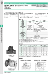
a.
Static Pressure (P) is the pressure within a duct which tends to burst the duct.
b.
Velocity Pressure (P) is the pressure which air in a duct exerts due to its motion.
c.
Total Pressure (PT) is the sum of the static pressure (P3) and the velocity pressure
(P).
PT=Ps+Pv
PRESSURE CLASSIFICATION OF DUCTS
Classification of duct systems by pressure and/or velocity are quite arbitrary. The
SHEET METAL and AIR CONDITIONING CONTRACTORS NATIONAL ASSOCIATION,
INC. (SMACNA), in developing duct, construction standards, established the following
breakdown:
a.
Low velocity
Up to 10.0 metres/second and up to 50mm (500 Pa) swg static pressure.
b. velocity
High
Above 10 metres/second.
i.
ii.
Medium Pressure: Up to 150mm (1500 Pa) swg static pressure.
High Pressure: Over 150mm (1500 Pa) swg static pressure up to 250mm
(2500 Pa) swg static pressure.
Note: Medium and high pressure ducts should be tested for leaks because performance of
systems having such ductwork is affected by air leaks to a greater extent than low
pressure systems.
In parts 18, 19 and 20, we covered the definitions of:
a)
volume of air handled;
b)
outlet velocity;
c)
total, static and velocity pressures.
We are now going to look at Static Pressure (Ps) as it effects fan performance.
Consider a complete air distribution system which may include heat exchangers, (coils)
filters, grilles, dampers and duct work. If air is forced through the system at a given rate
of flow, a certain static pressure will result. If air is forced through the same system at a
different flow rate, a different static pressure will exist. Most air distribution systems are
turbulent flow systems in which the static pressure varies as the square of the air flow
rate.
Ps=AQ2
where
Ps
A
=
Q
=
STATIC PRESSURE (Pa)
CONSTANT
VOLUME FLOW RATE (m3/s)
=
The graph constructed from this equation is called:
THE SYSTEM CHARACTERISTIC CURVE.
Field problems often will require. that both a fan performance curve and a system curve
be used. If a fan curve is available, a system curve can be drawn directly on it. Where
manufacturers data is in a multi rating table form it is possible to draw a fan curve based
on these tables.
EXAMPLE:
A test on a forward curved centrifugal fan gave the following results with the fan running
at 480 RPM.
Volume (m3/s)
0
1.0
2
3
4
5
6
7
Pressure (Pa)
750
675
650
700
675
550
350
125
The fan supplies air to a system for which the static pressure loss is calculated to be 615
Pa when the volume flow rate is 4.3 m3/s. Using the graph below, plot the fan and
system curves.
SOLUTION
Ps
615
A
=
=
=
AQ2
A 432
615 =33.3
(43)2
For selected volume flow rates, find the corresponding static pressure losses.
Volume(m3/s)
1.0
2.0
3.0
4.0
5.0
Pressure (Pa)
33.3
133.2
299.7
532.8
832.5
i
.L
U
9C
&
SYSTEM
CUR \'E
7C
6C
7 1\
.1
uj
;
___
4C
_
-
FAN
CURVE
ccLU
3C
2C
ic
0
1
2
3
VOLUME FLC"W
4
5
6
7
(t./s)
The fan characteristics (volume flow rate versus static pressure) and system characteristics
are now drawn on the graph. The condition at which the fan operates is given by the
point at which the two characteristics intersect.
Approximate Volume
Approximate Static Pressure
=
=
4.4 m3/s
630 Pa
When the fan is actually tested on start-up, it is found that the actual flow rate is only
2.25 m3/s and the measured static pressure is 557 Pa. The obvious solution is to increase
the fan speed, however, if the fan is operating in the unstable or surge area, the static
pressure must be reduced or another fan substituted.
To find the actual system characteristic:
Ps
A
=
AQ2
=
(2.25)2
=
110
Volume (m3/s)
LPressure (Pa)
1.0
1.5
2.0
2.5
3.0
3.5
110
247.5
440
687.5
990
1347J
Plot the actual system capacity on the graph and you can see that the static pressure cuts
the fan curve in more than one place. Therefore, the fan may settle down to any flow
rate where static pressure cuts the fan curve or it may surge between them.
FAN LAWS
It is often necessary to operate a fan at a speed other than the manufacturers tabulated
capacities due to the actual required volume of air.
The following is confined to those laws of most common use in air conditioning.
For a given Fan Size, Duct System and Air density.
i.
The volume varies proportional to the fan speed:
QL
Q2
ii.
=
The developed pressure is proportional to the square of the fan speed:
N1 2
P1
P2
iii.
Hi
N2
=
N2)
The power absorbed is proportional to the cube of the fan speed:
Wi
W2
where:
=
/N1\3
N21
Q = Volume flow rate (m3/s)
P = Pressure (Pa) (nor,nally static, but it can be velocity or total
pressure)
W = Watts (not installed but what is absorbed)
N = Revolutions per minute (Revs Is)
EXAMPLE
A fan delivers 7.3 m3/s of air against a static pressure of 383 Pa when rotating at 600
RPM (10 Rev/s) and absorbs 3.9 kW. If the fan speed is decreased to 400 RPM (6.7
Rev/s), find:
a.
b.
c.
the new volume;
the new static pressure;
the new absorbed power.
SOLUTION
Ni
Qi
Volume (m3Is)
=
Q2
=
Qi
N2
N1
N2
i 400
7.3
Q2=
m3/s
Q2=
Static Pressure (Pa)
600
P1
P2
=
1N1\2
N2)
=
iN12
..
P2
P1
=
N2/
400
600 )
P2
=
383
P2
=
170.2 Pa
=
Wi
W2
Power absorbed (kW)
2
=
1N13
N2 I
1N2
W1Nl
W2=
W2
=
I4 \3
:600 J
jJkW
PROBLEMS
A fan running at 350 RPM (5.83 Rev/s) supplies 6.2 m3/s when the static pressure is
187 Pa and absorbs 2.25 kW.
If the speed of the fan is increased to 480 RPM (8 Rev/s), find:
i.
ii.
iii.
the new air volume;
the new static pressure;
the new absorbed power.
A fan is required to supply 700 1/s. When it is started, it is found to have a capacity of
572 1/s when rotating at 400 RPM (6.7 Rev/s) and a static pressure of 478 Pa. The drive
motor installed is rated at 1.5 kW and the absorbed power is 850 Watts.
Find
i.
ii.
iii.
iv.
the required RPM;
the new static pressure;
the required absorbed power.
Would the existing motor still be suitable when the required air flow is achieved?
INSPECTION AND PROCEDURES
Before checking the fan and during inspection, the fan must be electrically isolated and all
disconnected switches locked in the "OFF" position. Where these are remote from the
fan prominent "DO NOT START' signs should be installed.
SYSTEM CHECKLIST
a.
A impeller comes to rest check if rotation is correct.
b.
See impeller is not installed backwards.
NOTE:
Fan rotation for centrifugal fans is clockwise or counter clockwise when
viewing the drive side and for axial fans when viewing the inlet.
c.
For belt driven fans check alignment of motor and fan pulleys.
d.
Check belt tension to the manufacturers recommendations - excessive tension will
shorten fan and motor bearing life. Belt should be re-adjusted after the first 48
hours of operation. Check condition of pulleys and belts.
e.
Check passages between inlets impeller blades and housing for damage from
corrosion or foreign matter trapped in impeller.
f.
Check ductwork for loose insulation, sheet metal, paper, etc,.
g.
Check conditions of coils, filters, etc. If dirty, clean.
h.
On fan equipped with inlet vane or damper control, check visually that the
vane/damper position agrees with the position of the control arm.
For double width fans check that both inlet/vane/dampers are synchronised. With
unbalance flow between inlets, the thrust on the bearings is also unbalanced and it often
leads also to surge conditions in the fan.
i.
After completing the system check list, put the fan back into operation.
j.
Inspect the entire system including the fan, fan plenum and all ductwork for leaks.
Leaks may be detected by sound, smoke, feel, soap solution, etc. Common leak
sources are access doors, coils, duct seams, fan outlet connection, etc., which
must be sealed.
TROUBLESHOOTING CHART
NOISE
a.
Impeller Hitting Inlet Ring
PROBABLE CA USE
i
ii
iii
iv
v
vi
b.
Impeller not centred in inlet ring.
Inlet ring damaged.
Crooked or damaged impeller.
Shaft loose on bearings.
Impeller loose on bearings.
Bearing loose on bearing support.
Drive
PROBABLE CAUSE
i
ii
iii
iv
v
vi
vii
viii
ix
x
xi
c.
Bearing
PROBABLE CA USE
i
ii
iii
iv
v
vi
d.
Defective bearing.
Needs lubrication.
Loose on bearing support.
Seals misaligned.
Worn bearing.
Corrosion between inner race and shaft.
Shaft Seal Squeal
PROBABLE CA USE
i
ii
e.
Pulley not tight on shaft (motor and/or fan).
Belts too loose.
Belts too tight.
Belts wrong cross section.
Belts not "matched" in length on multi belt drive.
Variable pitch pulleys not adjusted so each groove has same pitch diameter.
Misaligned pulleys.
Worn belts.
Motor, motor base or fan not securely anchored.
Belts oily or dirty.
Incorrect drive selection.
Needs lubrication.
Misaligned.
Impeller
PROBABLE CA USE
i
ii
Loose on shaft.
Unbalanced.
f.
Shaft
PROBABLE CAUSE
i
ii
g.
Bent.
If more than two bearings are on a shaft, they must be properly aligned.
High Air Velocity
PROBABLE CAUSE
i
ii
iii
iv
h.
Ductwork too small for application.
Fan selection too small for application.
Registers or grilles too small for application.
Heating or cooling coil with insufficient face area for application.
Rattles, Rumbles or Whistles
PROBABLE CA USE
i
ii
iii
iv
Dampers.
Registers.
Grilles.
Sharp elbows.
v
vi
vii
viii
ix
x
xi
xii
Sudden expansion in ductwork.
Sudden contraction in ductwork.
Turning vanes.
Leaks in ductwork.
Fins on coils.
Vibrating ductwork.
Vibrating cabinet sections.
Vibrating parts not isolated from building.
Pulsation or Surge
PROBABLE CA USE
i
ii
iii
Restricted system causing fan to operate at poor point of ratings.
Fan too large for application.
Ducts vibrate at some frequency as fan pulsations.
LOW VOLUME
PROBABLE CA USE
i
ii
iii
iv
v
vi
vii
viii
Forward curved impeller installed backwards.
Fan running backwards.
Fan speed to low.
Actual system is more resistance to flow than calculated.
Dampers closed.
Registers closed.
Leaks in supply duct.
Insulating duct liner loose.
ix
x
xi
xii
Filters dirty or clogged.
Coils dirty or clogged.
Obstructed fan inlet.
No straight duct at fan outlet.
HIGH VOLUME
PROBABLE CA USE
i
ii
iii
iv
v
Oversized ductwork.
Access door/s open.
Registers or grilles not installed.
Dampers set to by-pass coils.
Filters not in place.
STATIC PRESSURE LOW - VOLUME HIGH
PROBABLE CA USES
i
ii
System has less resistance than calculated. This is a common occurrence. Fan
speed may be reduced to obtain desired flow rate. This will also reduce absorbed
power.
Fan speed to high.
STATIC PRESSURE HIGH - VOL ME LOW
PROBA BLE CAUSES
i
ii
iii
iv
Obstruction in system.
Dirty filters.
Dirty coils.
System too restricted.
ABSORBED POWER HIGH
PROBABLE CA USES
i
ii
iii
iv
v
vi
viii
Backward inclined impeller installed backwards.
Fan speed to high.
Oversized ductwork.
Face and by-pass dampers oriented so dampers are open at same time by-pass
dampers are open.
Filters left out.
Access door/s open.
Fan not operating at efficient point of rating. Fan size or type may not be best for
application.
FAN DOES NOT OPERATE
ELECTRICAL OR MECHANICAL
Mechanical and electrical pr&ilems are usually straight forward and are analysed in a
routine manner by service personnel. In this category are blow fuses, broken belts,
looses pulleys, electricity burned off, impeller touching scroll and motor too small and
overload protector has broken circuit.
BEARING REPLACEMENT
If a fan shows an increase in vibration, it generally indicates that the bearings require
replacing or servicing. When bearings are to be replaced, they should be removed from
the shaft with a bearing puller and the same tool can, by relocating the jack nut, be used
on site to install the bearing. Always check the fan shaft for wear before replacing the
bearing and if the shaft is worn, it too must be replaced. After replacement of bearings,
run the fan without a load for a short period to allow new components to bed in.
rLATE
r
BEARING
SHPcT
PIPE ON INN/
RACE ONLY
Driving a bearing onto a shaft.
Using a bearing puller.
END OF SECTION 2
Additional and more detailed information pertaining to SECTION 2 will be found in the
following:
AIR CONDITIONING ENGINEERING 2ND EDITION S.I. UNITS
Whitstable Litho Ltd. Whitstable Kent.
T.P.C. TRAINING SYSTEMS (Air Handling Systems)
Technical Publishing Company, Barrington. Illinois.
ASHRAE SYSTEMS AND EOUIPMENT 1967
American Society of Heating, Refrigerating and Air Conditioning Engineers, Inc., New
York.
START. TEST AND BALANCE
National Joint Steamfitters - Pipefitters.
HOW TO DESIGN HEATING. COOLING COMFORT SYSTEMS -3 Edition
Business News Publishing Company, Birmingham, Michigan.
VARIOUS MANUFACTURERS INSTALLATIONS. START-UP. SERVICE
MANUALS AND BULLETINS
and many other publications.
VENTILATION NR13
Learning Outcome 3
Student Worksheet 3:1
Question 1.
The maximum pressure a fan can develop occurs when the ductwork connected to the fan
is:
a)
b)
open to atmosphere, or
closed off and all openings sealed.
Question 2.
In an air conditioning installation, where would you most expect to come across a radial
blade centrifugal fan?
Question 3.
Describe and show, by means of a sketch, the difference between a tube axial and vane
axial fan.
Question 5.
Give the formula and state the definition which explains what happens to the pressure in a
constant duct system if the air flow is varied.
Question 6.
If, when starting a fan on a new system, the flow rate was found to be high and the static
pressure lower than calculated, would this be common or an uncommon occurrence?
Give reasons for your answer.
Question 7.
Explain fully what is meant by the term system characteristic curve as used in fan
applications.
Question 8.
A fan is required to supply 8.5 m3Is when operating at 650 RPM against a static pressure
of 850 Pa. On start-up, the capacity is found to be 9.75 m3/s and the static pressure is
measured to be 565 Pa. A 4.5 kW motor is installed and the absorbed power of the fan
is 4.7 kW.
i.
How would you fix the problem?
ii.
What would be the static pressure for the fan at the correct flow rate?
iii.
Does the motor need to be changed once the flow rate is corrected?
iv.
What is the absorbed power for the fan at the correct flow rate?
SHOW ALL FORMULA AND CALCULATIONS
-
CALCULATIONS
Question 9
What is meant by the term "surge" as applied in fan terminology and how can it be
corrected?
AIR CLEAI1ING ASSEMBLIES
1.
One of the concepts of air conditioning is that the air introduced
into the zone should be clean. Some of the advantages of air being
cleaned is that dirt removed by the filter keeps the inside of the
building cleaner and clean air passinq over a dehumidifying coil
prevents the moisture and dust forining a muddy coating on the coil
reducing its heat exchange efficiency and increasing its pressure
Increased p'essure drop will result -in less air flow, again
drop.
reducing the heat exchange efficiency, and causes more power to be
motor/s.
absorbed by the f-
2.
a unit of measurement
Airborne particles ar measured in
which is defined as one millionth of a metre. For comparison, consider
the following:
Smallest Size
Particle To Be
Seen With The
Naked Eye
20 Microns Dia.
Humar Blood
Corpuscle
10 Micron Dia.
Tobacco
Smoke
1/4 Micro
Dia.
Greatly Magnified View Showing Relative Particle Size
3.
Operating characteristics and the performance of an air filter are
described or stated by a number of parameters.
()
Rac.d Ca.pc.cJy: is expressed in cubic metres per second (m3Is)
is the recommended maximum rate at which air should be passed
through a filter in service. Rated face velocity expressed in
metres per second (m/s) is an alternative method of deriving
capacity.
Capacities are s2metimes expressed in litres per
second (l/s) 1000 1/s = 1 m/s.
1/
(b)
c4.2.aj1c: expressed in Pascals (Pa) is the pressure drop
developed across the filter as air passes through it. In most
types of filters, the resistance is also a function of the amount
with dust, the
of dirt in the filter. As the filter los
res-.stance
resistance increases. It is normal to quote the c.e
for fixed panel type filters, but for automatic self cleaning
filters, the averace operating resstanoe is generally used.
Ic)
VuAt HoE.d.ng Capac.L4j: is the mass of dirt in the filter which
will increase the resistance at rated capacity either to or
through a pre-determined valve of resistance and this is a more
significant figure than clean resistance. The dust holding
Velocity also affects dust
capacity is normally given in grars.
holding capacity.
Id)
Eceicu: or more correctly arrestance efficiency is generally
defined as the amount of matter retained by the filter expressed
as a percentage of the amount entering it. Both atmospheric
air and test dusts are used in filter testing standards. As to
of dirt retained by the filter
the measurement of the
there are a number of ways in which this can be assessed.
Ce)
(i)
Gravimetric or mass test - the amount of dust is determined
by weighing the dust and the filter collecting it.
(ii)
Dust-spct, blackness or discolouration test, all meaning
the anount of dust being measured by assessing the soiling
of filter papers through which the air has been passed.
(iii)
Count tests in which the nurrber of particles is counted
by sanplino microscopic examination or by automatic
particle counters.
(iv)
Opacity test in which the opacity of an air stream
containino dust in suspension is assessed.
FiLWt Lc: or the time a filter will operate without attention
is a function of four parameters.
(i)
Dust holding capacity.
(ii)
Gravimetric efficiency.
(iii)
Dust concentration in air being filtered.
(iv)
Rate of air through filter.
The mass of dust being fed to the filter is the product Of the
dust concentration and the air flow rate. The mass retained by
the filter is the mass fed multiplied by the gravimetric
The filter life o
b calculated from this fi'e
d the filters dust hold-.r.p capaciy.
efficiency.
Often when long periods of time between servicing, or when dirt
concentration is high, filter life can be increased by decreasing
the rate of air flow through the filter.
4.
Althougn there are many different types of filters available, they all
fit into one or a combination of three basic cateoories:
(a)
Vity
AM4a.rcc.:
filters remove dust particles from the air stream
by trapping them between the fibres of a
filter mat, which may be of cellulose,
cloth, felt, glass, paper or specially
Dry
developed synthetic materials.
arrestance filters are available in both
the fixed panel (shown be. 1w ) or roll
types (shown oppo5\te).
roll type Cry meCia filter
Pyracube oeep be
fl!C'
The media texture necessary
for high efficiency requires
low surface velocity to keep
the resistance low. To
obtain this low velocity,
the area of the filter can be
increased within the filter
frame either by pleating or
forming it in corrugations
or by shaping and sewing it
into a ser.i-supporting
basket.
This increases the depth of
the filter and also increases
the effective surface area
up to four times the filter
face area depending on the
cortfi gurati on.
All the dry media filter
mentioned so far can be cleaned by vacuum cleaning, washing
or some other method, However1
a dry media filter which is
never cleaned is the .4,scZue
Or EE?.4 (Hich Efficiency
Particulate- Air) filter.
Irrnieee ar%ø agitate in bath of warm
01 C0Ø waSf with lefgaM
These use a glass paper medi?
and have an efficiency of
The paper is arranged
99.97.
in an extreme ccicering
arrangement separated by pieces
of corrugated material,
generally aluminium. The
filter pack of paper and
separators are sealed in a
strong frame generally made
of metal.
Pan of ar absolute HEPA filter pack. SnOwing
corrugateø separators
higt e1cteriCy Idler
Ib)
Vocou4: All the dry media filters, with the exception of the
H??A filters, can be impregnated with an adhesive, normally a
gel or light oil, to increase their efficiency. Generally medias
imDregnated with an adhesive cannot be satisfactorily cleaned.
Metal viscous oil filters are available as simple fixed panel
filters or as automatic types which provide for the panels to be
cleaned and re-oiled by passing them through an oil bath in the
base of the filter frame. The filters are normally constructed
from aluminium.
I
Section of filter media (approx.
actual size)
3
Cross section of filter media
showing airflow pattern
-
/
I
(c)
Eecc': filters UtlilZ€ the principle that unlike electrostatically charged bodies are attracted to each other. The air
to be cleaned is first passed tnroucr a unit called the
r.se",
which consists of a
series of earthed
electrodes havino
fine tungsten wires
\
spaced centrally
-
:
When
between them.
a high voltage D.C.
CELL
wire and a vast number
of oris are generated
in the intervening
space.
Prsncipe 01 oera.c' of l3ri1rC' ecrc'c ar 41
As the airborne dust particles oass through this highly ,onised
space, they are given a specific electrostatic charge. The
charged particles then pass through a collector cell where an
electrostatic field between charged plates forces them towards a
plate of opposite polarity where they adhere. An adhesive is
applied to the plates to ensure retention. The unit is cleaned
by flushing away the adhesive and precipitated dirt with water.
Fresh adhesive is then applied before placing the filter back in
service.
Direct Current at high voltage, 13 kV for the wires and earthed
plates and 6.5 kV for the collector cells parallel plates, which
are alternatively earthed, is supplied from a 240 volt, 50 cycle,
single phase power pack supply
A variation of the electronic fiter is the io,-2tror AggZarriertor.
An agglomerator combines an ioniser and cell fed with high voltage
direct current from a power pack but the cells are not coated with
adhesive.
In addition, there is a dirt storage section imediately.
following the collector cells.
,O.gJ?ta
•
Prirc:ie c ceration of IOfl:1O'e aggmerator type eiecroric air tIter.
The ionised dust is precipitated onto the cell plates and here it
into large particles and as there is no adhesive,
gets blo:n ff again. The large agglomerated particles are then 'scarried into the dirt storace section where, because of their
large size, they are effectively 100% trapped.
agp1
NOTE:
5.
A:iy
oi. 'Le.p.JJ. o £ corLc aL'L iLct.o m
bcL doiic. cth .tJi.e pa.'v. OFF. 1)0 no o..tcmp.t tc byp
ay
o .thc
c'caZ
guw.d .LnaLd.
Since the effectiveness of an air conditioning system is dependent on
the amount of air flowing, care should be takento ensure that the
resistance of the system does not materially increase. Draught gauges
installed across the filter will provide a continuous reading of the
filter resistance.
The point at which service is required alters
depending on system or manufacturers recornendations.
As a general
rule, filters should be serviced before the total air flow in the
system drops by 10% and/or the pressure drop across the filter rises
25OPa.
..
.
6.
in some locations the odour of air iray need to be controlled as well
as the cleanliness. Aivczted Crbor., which is a special form of
carbon, is normally used for odour control. Activated carbon is
capable of sok-r.: z
or adsorbino gases and vapours, just as silica
gel adsorbs moisture.
The air is passed through beds of activated
carbon1 when the carbon is saturated, it can be rejuvenated by heating
to 540uC.
7.
There is nothing to prevent the installation of different types of
filters in series in the one air duct. An example is the use of a
panel type dry fabric filter as a pre-filter to remove the larger
particle of dust leaving a HEPA filter to collect only the finer
material. A second example is the installation of an after filter in
an eictrstct'2c pr;ttor, again normally a dry fabric panel type,
in case of power failure.
VENTILATION NR 13
LEARNING OUTCOME 3
STUDENT WORKSHEET 3:2
Question 1.
List the three categories of filters.
(A)
(B)
(C)
Question 2.
Which filter is the most efficient and what type of media does
it use?
Question 3.
How many types of electric filters are there ?
Question 4.
How would you check if a filter required cleaning or replacing?
Question 5.
What metal is used in the manufacture of Metal Oil Filters?
(2)
Question 6.
What precaution niust be observed before working on any electronic
type filter?
Question 7.
How is odour generally filtered out of the air in an air
conditioning system?
Question 8.
What do you expect to happen to a Direct Expansion coil if the
filters are:
(A) Removed from the system for a reasonable period of time?
(B) Allowed to clogg up?
LEARNING OUTCOME 4
Assessment:
Performance:
Short answer, practical exercise.
a.
Briefly describe the correct operating procedures for a
range of test equipment, commonly used on
ventilation equipment, and state how the information
gathered could be used.
b.
Use the most appropriate items of test equipment to
take the following measurements:
- air Volume
- air Velocity
- air Pressure
- sound power level
from various points on a ventilation/air conditioning
system.
c.
Whilst carrying out the above procedures the student
will explain to his/her lecturer how they have arrived
at their measurements, what they consider to be the
most appropriate units to use and how the above
measurements are related.
TEST EOUIPMENT
NOISE/VIBRATION
-
-
Practicality
Types available
Usage and care
Calibration
Flow characteristics
Appropriate formulas
Units of measurements
Application
Use of information gathered
Permanently installed/portable
Expected results
Source of noise
Nature of sound
Frequency
Acceptable levels
Measurement
Transmission
Controlling noise/vibration
Attenuation
Absorption
Fault finding
Suggested teaching time: 4 hours.
Suggested teaching time: 4 hours.
AIR BALANCING INSTRUMENTS
Before you can attempt to balance an air stream, you must have accurate,
reliable instruments. All instruments with the exception of the pitot
tube and manorneter need to be reàalibrated at intervals of not more than
If an instrument is dropped, or otherwise damaged, it should
siz months.
be recalibrated. If there is any doubt about the accuracy of an instrument,
it should be checked against another instrument measuring the same quantity
Each instruments should
and be recalibrated if the answers do not agree.
carry a calibration record.
Read the manufacturer's instructions and become familiar with your air
testing instruments before using them on an actual job.
1.
ROTATIONAL SPEEV MEASURING INSTRUMENTS
Measurement of rotational spad will be required to determine whether
a fan is working as specified. iechanical tachometers are normally
used where the shaft of the fan or motor is accessible. Where it is
dangerous or not tossible to use a mechanical tachometer, a stroboscope
is usually employed.
(a)
Revolution Counter (Speed Indicator)
A small, inexpensive, hand held counting device that is pressed
to the centre of a rotating shaft for a timed period. It requires
the use of a stop watch and cannot usually be reset to zero
--
L
'\I
(A) Speed indicator wtu several tips
(B) A stop-watch shou'd be used for timing wtien rcadlng RPM with
speed indicator
Speed indicator
=
R. P. M.
where:
!tl
-
No
t
R.P.M.
No
t
=
=
=
=
Shaft sveed revolutions per minute.
Original reading.
Final reading.
Time interval, minutes.
(b)
Dial Tachometer (Centrifugal Type)
A hand held instrument that directly
indicates the instantaneous speed on
the face of a dial.
/
Tachometer with sângle speed range
•
Tachometer with multiple
speed ranges
Cc)
Chromometric Tachometer
Ttp to be
inserled in
countersunk
hole in end
of shaft
A hand held instrument that
combines a precision stop watch
and a revolution counter in an
instrument. The scale is
calibrated so that after 6 seconds
the instrument stops accumulating
Each actual
revolutions.
revolution of the instrument
__
Press
button
to start
I
-
indicates 10 revolutions on the
dial, so that readings are directly
in R.P.M. Repeatedly pressing the
activating button without contact
with a rotating shaft, on allowing
the timer to run down, will da'nage
this instrument.
ChrortometriC tachometer
Always keep tachometer and
aft attachments in case when nt in
use
1i
Reang shaft speed
Cd)
Stroboscooe
This instrument is a source of variable frequency liciht and the
techniciue in using it is to match the light frequency to the
rotational soeed.
chalk mark is made
on the pulley and the
stroboscope adjusted
t
tO
•
D
SLdL.LOIiLy WL1iL
the pulley is rotating
The frequency setting
on the stroboscope may,
however, be a multiple
or sub-multiple of the
actual shaft speed and
such errors of harmonics
need to be eliminated
t o assess the correct
speed. The stroboscope
•
C
-
i-s norrnalty used on
site only when it is
%
inivossible to use a
mechanical tachometer.
Stroboscope
•
2.
PESSLIRE MEASUPSTNG IWSTRUMEWTS
For in duct measurements a pitot tube with an adjustable manometer
will give the most reliable results. These need no calibration and
are consistent.
In practice the lower pressure readability on the
manometer is about 10 Pa (4 rn/s or 1.0 mm).
(a)
U-Tube 1anorneter
This type of manometer is a simple and useful instrument for the
measuring of partial vacuums and oressures, both for air and
hydronic systems.
In its simplest form, the manometer consists
of a U shaped glass or plastic tube partially filled with liquid.
1
h
2#2
4
341
4
4
1
(A) Levels at zero at scale
-
I
h
(B) Levels below scale zero
Reading the U-tube manometer
(C) Levels above scale zero
2
A difference in heiqht of the two fluid columns denotes d
difference in pressure in the two leqs. When reading a U-tube
manometer, observe that the liquid level in one leg falls while
the liquid in the other leg rises. The oressure It is the sum of
the readings at these two levels.
(b)
Well -Type Manometer
As described previously, the U-tube manometer requires two readings.
The well type nanometer
requires only that one reading
Pressum
be taken. The scale is
corrected to compensate for
the change in reservoir
h
liquid level so that the well
- ____ - ___r
- does not have to be excessively large.
T
.4
______
_____
________
(A) Equal pressure (atmospheric)
on both legs
(B) Pressure imposed on well
Well-type manometer
Cc)
Inclined Manometer (Draft GauQe)
The inclined manometer is often called a draft gauge because of
its use in measuring the draft in boilers.
The inclined manometer is a variation of the well type, but the
indicator leg is placed in a sloping position rather than vertical.
The purpose of this is to
Pressure
improve accuracy in reading
the scale. For the same
jo
_____
(A) Equal pressure (atmospheric)
on both 'egs
Levekn
Screw
_____
(B) Pressure imposed on incned
leg
(C) Typical incined manometer
ncIined manometer
Adjustment
Knob
pressure the
the incl'i.ne
considerably
the vertical
distance of
scale is
greater than
scale.
The inclined manometer is
commonly used for measuring
low pressures of 50mm
(500 Pa) or less.
(d)
Combination Inclined - Vertical Manometers
Many U and well type manometers may also be used as vertical
manometers. This allows for reading both high and low pressures
on the same instrument.
I
LUVOIII 19
10$ It
Screw
Knob
i
Combination inclined-vertical manometer
NOTE:
in most coriviercial instruments,, the fluid used is a light
oil, normally with a specific gravity of 0.83.
It is important tnat only the correct fluid is used in
each ins trwnent as the scale is corrected for the
designated specific gravity.
Ce)
Portable Air Pressure (auges (Dry-Tyre)
Manometers have the disadvantaqe of containinq liquid which can
be spilled or contaminated, and they must be accurately levelled.
One such operates
Dry type draft gauges overcome these problems.
on a bellows that actuates
a helix which, in turn,
moves a pointer across a
Others
printed scale.
operate by weight or blade
displacement. Generally,
INCHIS oc wAlli
dry gauges are not as
accurate as a liquid
. 30
20
filled U-tube and
1
.40
. O
frequently do not stand
So
up to rough handling.
"I,,>
Several instruments are
required
to cover the
\
normal ranges encountered
\ MAGNEHELIC A
in average air condition\
There are
ing jobs.
approximately 30 available
pressure ranges in this
- instrument.
n
Dry type draft gage
3.
PITOT TLIE
The Pitot tube (named after the Frenchman, Pitot, who designed it)
is an instrument for measuring Static, Velocity and Total pressure
in a stream of air or gas.
It consists of two concentric tubes, usually "1" shaped for convenient
handling and which ends in two separate outlets for connection to a
manometer.
The instrument is inserted into the air stream, parallel
to the direction of flow and with the openings always pointed upstream.
The inner tube, facing into the air stream, conveys the impact or
total pressure.
The outer tube has a number of small radial holes
in its wall and the annular space between the two tubes conveys the
static pressure.
5"
16D
-.----1"
4
2k" . 8D
Din.
A
t
r,,
_____
/ C'
iiç
,1
*
-
-
-
-
______
I
____
I-
16
1D
nks and burrs.
Free from Burrs
90+1
Note:
-
- SECTIO?Z A-A
-
other sizes of pitot tubes when required. may be built using the same geometric
proportions with the exception that the Static orifices on sizes larger than
standard may not exceed . 04" In diameter. The minimum pitot tube stem diameter
recognized under this code shall be . 10'. In no case shall the stem diameter
exceed 1130 of the test duct diameter.
C
STATIC PRESSURE
liii 1'OUTER TUBING
5/16'
-
I
,,i
INNER TUBING
-
O.D. x Approx
18 B & S Ga.
TOTAL PRESSURE
STATIC
PRtSSL(
TU&
\jLOW-
TOTAL
PR(SSTW(
_____
PTOTQ
TOTAL PRTSS -STAT( PITSS
P5(55
SHOWS SOPASATE STA1 AJID TOTAL P5(5Sj(
lUSTS
IALAS1Wsl VttXJTY P5(55*(
rcs w P9ccnRc
urIIRcuTuT'
• PITOT TUSE SU(SES TOTAL A?(D STATIC PRESSURES.
UANOMUTER MEASURES VELOCITY PRESSURE (DFF(RNC( BETWEEN TOTAL AND STATIC PREURES1.
Pitot tube hook-ups are shown in the following figures. It can be
seen from these figures that whatever the condition, the hook-up for
reading velocity pressure remains unchanged; the impact (total) tube
goes to the high pressure side and the static tubes goes to the law
pressure side.
___
-
U:,
--
1119
1k:
.4
fZhAU.T
t
tLJU--TWAL
ML.AIRI
LXjt&USI UUCT-TOIAL PWLSSUk IS posrTIvr
-Mr F1O-
-
V __
__
SUPPLY DUCT-TOTAL PRESSURE IS POSITIVE
DETERMINATION OF FLOW VOLUME
The object of an actual test usually is not only to determine the flow
velocity at a certain point, but to determine the volume of air flowing
through a duct.
EXAMPLE
From a 10 point traverse of a 300mm round duct the velocity pressures are
tabulated and corresponding velocities found and also tabulated, as shown
in the following table, the average velocity being found as the average
of all velocities.
Horizontal
Verti cal
mm
n/s
mm
rn/s
1.3
1.8
2.3
2.8
3.3
3.6
3.0
2.6
1.8
1.0
4.6
5.4
6.1
6.8
7.3
7.7
7.0
6.5
5.4
4.0
1.0
1.5
2.0
3.0
3.6
3.3
3.0
2.8
1.8
1.3
4.0
4.9
5.7
7.0
7.7
7.3
7.0
6.8
5.4
4.6
60.8
60.4
Average
60.6 rn/s
It is necessary to convert each velocity pressure reading into velocit-y,
and then to average these velocities.
An incorrect answer will be obtained if velocity pressures are averaged
and the result converted to velocity.
Having found the average velocity, the volume of air flowing can be
calculated as follows:
= 300mm round
Duct size:
Duct Area: = 0.0707 m2 (approx.)
= 60.6 rn/s
Velocity:
Volume:
4.
=
=
=
Velocity x Area
60.6 x 0.0707
4.28 xn3/s
ANEMOMETERS
Critical to the proper use of any anemometer is the determination and
application of the correction factor which will convert the anemometer
reading into a reasonable accurate velocity or volume measurement.
It is absolutely essential that the correction factor be used for
each instrument.
The manufacturer tests each type of supply outlet and return inlet
to determine the "K-factors" for all of the different types of
instruments. The manufacturer also determines the location on the
face for making measurements.
(a.)
Ro.tatn
Vane. lP'wpeLeeA) Aimome.tvt
The propeller or rotating vane anemometer consists of a light
weight, wind driven wheel connected through a gear train to a
set of recording dials
that read the linear metres
of air passing throuah the
ping Lever
wheel in a measured time.
The instrument is made in
Zero Reset
various sizes; 75mm, 100mm
Lever
and 150mm diameter sizes
being the most common.
Each instrument requires
individual calibration.
Most of these instruments
are not sensitive for use
below 1.0 rn/s. Their useful
S
range being from 1.0 m/s
to 10 in/s.
The instrument is available
/
i
as a manual timed tyre in
1/
which a watch or stop watch
is required for timing or
with a built-in automatic
stop watch.
-
Rotating vane anemometer
Where remote readings or pulsating
flows may be encountered, an
instrument with electrical remote
transmission is generally employed.
Vane Anemometer with electrical remote transmission
The rotating vane anemometer is used both with fixed stationary
readings and travelling averaging time readings. Both give the same
accuracy.
(b)
Peçee.ctLng VCLIIC. Anemome.te
This instrument is commonly known and referred to as a Velonieter.
The deflecting vane anemometer consists of a pivoted vane
enclosed in a case. Air exerts a pressure on the vane as it
passes through the instrument from an upstream to
downstream oDening.
The movement of the vane is
resisted
by
a
hair-spring
and dampening magnet.
The instrument gives instantaneous readings of
directional velocities on an indicating scale.
The instrument can be used with various types of
remote connected measuring tips or jets - each
of which must be individually calibrated with its
individual instrument and tubing.
Air Flowmeter
Probe
U
-
II
Probe
for use
with diffusers
Static
Pressure
Probe
Low Velocity
Probe
Deflecting vane anemometer
--
Measuring
drafts
or other
tow air
velocities, as at
exhaust hoods
Measuring
air velocity
at plating
tank
StaUc pressures
Measuring
air velocities
at supply
openings
Typical applications of deflecting vane anemometer
(ci
Vic..t Re.acLthg Anemometc/L (FZo'rLte and 5nLdeed)
Similar to the already described vane anemometer, however, these
include a calibrated scale built into the instrument. The
Plorite type, shown below, is limited in use because of the scale
limitations.
4
Side Wall Register
Floor Regist&
Baseboard Dittuser
Retrigeration Grille
Pocket type deflecting vane anemometer, and typical applications
The Bridled vane anemometer, shown below, is often used with
special attachments that direct air through the instrument.
The Bridled anemometer is also often used with an extension
handle to reach high side or ceiling outlets and is provided with
a scale lock which locks the indicator in place once the reading
is made.
DE-CAST
cmu-HOuNG
(WUATTh
SPIING
-
-
• ____
SCALA
,
n•YA,
*OTO
(B) View showing vane
Bridled vane anemometer
(A) View
showing scale
lao
-
Measunnggrifle
velocity; use of
handle minimizes
interference with
air stream
-
-
-,-
-- --•
.LW
&W r..-_
a
,
scale Iocl
• .
. .
•
.
.
.
*..
a a
I
i_
e •
•
/
(
'•'%
Bridled vane anemometer with air scoop
housing used to measure diffuser outlet
velocity
Bridled vane anemometer
Both the Florite and Bridled vane anemometers require considerable
judgernent to obtain average velocities, especially when recording
at right angles to the air flow.
Cd)
Hot W.L'Le Atternometeii
This instrument utilizes the principle that resistance of a
heated wire will change with temperature. A probe with a wire
element energized by batteries is connected to the instrument.
As the air flows over the element in the probe, the temperature
of the element is changed from that which exists for still air and
this change is indicated as a velocity on the scale of the
instrument.
-U.
r
____
'
-;
..
•.
____
S(LECTOR
*1_j
i&
9
_
_______
U
! EHTADJUSTMENT
_
I
:
-
__
AIR METER
2.SOO.Qt
OTK.PATPCND.
SEPIAL
o
_________
ill ISTAT PIOBUCTS •iViStU
U USCUICA
I?sW
U1B*RC
%CILET . PA.
The instrument is also provided with temperature scales that can
be read by selecting the correct button. Static pressure can
also be measured on some instruments if the proper probe is
supplied with the instrument.
The probe of the
"hot wire" anemometer is quite
directional
an d
must be used in
the precise location
recommended by the
outlet manufacturer.
Probe
Measuring
positive
static
pressure
K
Measuring air
velocity in neck of a
round diftuser
Measuring negative static pressure
Measurino qnlle
tae velocity
_
_______
-
Typical applications of the hot-wire anemometer to air flow measurements
(e)
VaiabJLe. Akciz Fe..ovxqeJejt.
The anemometer shown is classified as a variable area floeter.
Air flowing from the probe enters the bottom of the meter where
it impinges against the bottom of a small ball. This causes the
ball to rise in a tube which is tapered so that the flow area
increases at the rises. The height to which the ball rises is
proportional to the air velocity, which can be read directly in
metres per second on an appropriately graduated scale.
The probe, the instrument tube and connecting tubing comprise a
calibrated instrument.
It is, therefore, important to use the
proper probe, and that the length of the connecting tube not be
changed.
When using a suitable probe, the instrument can be used to measure
static pressure.
Measuhng
grille velocity
Iowmeter
.0
t
JfY
il /
ii,
///
/./
,---...-/
I---
Flowmeter kit with probes,
accessories an case
Variable area flowmeter
-J
5.
AiR TEMPERATURE MV RELArTVE HUMIVITY
To get a simultaneous readino of wet and dry bulb temperatures, a wet
and dry bulb thermometer are mounted side by side on a frame fitted
by which the two thermometers can be whirled through the air.
The whirling is stopped from
time to time and readings taken
until the temperature 'eading
of the wet bulb thermometer
starts to rise, the lowest
____
____
'
-
reading being taken as the wet
bulb thermometer.
A mercury-in-glass thermometer
may be needed to check whether
air density corrections should
he made at the final stage in
measuring total volume flow
from the fan(s). A high degree
of accuracy is unnecessary.
Electric thermometers may also
he used and these are usually
one of two types. One is the
thermocouple type, in which the
thermocouple generates an
electrical current when
temperature varies between the
hot and cold junction of
By reading
dissimilar metals.
the amount of current generated,
an indication of temperature
is given.
The other type of electric
thermometer is the resistance
thermometer, the type generally
known as the Rot Wire Anemometer
Sling psychrometer with wet bulb and dry bulb stems
and handle to whirl the instrument until the wet bulb
settles.
(see Page 23) covered elsewhere,
since it also is used as an air
velocity measuring instrument.
6.
VOLTAGE ANV CURRE&rr
It is important to check all motor current at the beginning of
baZ.ancing to see if it is within design range.
A combined induction ammeter and
voltmeter is generally used for
current measurement. This does
not have to be wired into the
circuit; it is easy to use and
has an accuracy of 3% full scale.
The trigger operated jaws of the
ammeter is placed around the
conductor at any convenient point
and the induced current in the
ammeter is indicated as the
actual current flow in the
conductor.
Insulation does not
affect the reading, but the
instrument will only work on a
single conductor - not a twin
cable. With three phase motors,
take readinas on each of the three
wires and average the results.
The instrument described can also
be used for measuring voltage,
although in practice measurements
are not often required.
I nduct ion Ammeter
7.
SOLINV LEVEL
Noise and vibration caused by fans, punrns, compressors, etc., may
produce sound. Noise is simply undesirable sound. The frequency
range of human hearing varies from person to person and age reduces
ability to hear higher frequencies. The audio-frequency range for
humans is generally 20 Hz to 20,000 Hz.
The audio-frequency range is divided into 10 groups (octave bands).
The centre frequency (geometric mean frequency) of each band is half
that of the next higher band. High frequency will be heard as highpitched sound.
number
Frequency timits
(Nz)
Centre frequency
(Hz)
1
2
3
4
5
6
7
8
9
10
20-50
50-78
78-200
200-312
312-COO
800- 1 250
1 250-320(1
3200-5000
5000-12800
12 800- 20 000
315
63
125
250
500
1 000
2000
4000
8000
16 000
Band
-I,
The irritation caused by noise depends upon frequency and loudness.
The decibel
The unit used for sound measurement is the Decibel (dR).
scale is a logarithmic scale which results in a small ranqe of numbers.
to cover the audible range of the human ear.
It is to be noted that decibels cannot be added or subtracted by
ordinary arithmetic.
For each frequency band, noises as experienced by the human ear have
been ascertained and the noise rating (N.R.) curves established
(N.R. curves are in S.I. units) the older N.C. curves are not.
(Both curves are interchangeable).
OCTAVE BAND
CENTRE FREQUENCIES
63
250
1000
4000
100
1100
, 95
90
-90
80
• 85
- 80
70
-15
- 70
60
65
V
-J
LU
>
LU
-J
60
LU
(/)
C,)
LU
Cl)
5c
55
50
-
4C
0
z
- 40
0
z
C,)
35
30
2(
' 25
20
1C
- 15
-
315
125
500
2000
10
8000
OCTAVE BAND CENTRE FREQUENCIES NR CURVES
The N.R. curves are used to determine the noise present in a situation;
N.R. ratings above 85 can cause tenmorary or permanent hearing damage.
Table
Recommended noise ratings
Recommended nois
rating curve
NA 20
NR25
NR3O
NR35
NR4O
NR45
NA 50 and above
Typical application
_____________________________________________________
Concert halls, opera halls. Sound studios.
large theatres
Lecture rooms, small theatres, cathedrals
Living rooms, board rooms, offices.
conferences, small lecture rooms
Holel rooms, hospital wards, small offices
Restaurants, bars, night clubs, departmental
stores, lobbies, post offices, reception
areas. shops
Cafeterias. canteens. supermarkets, swimming
pools. bowling clubs, laundry rooms.
kitchens, computer rooms, accounting
machine rooms
Justifiable in factories
To arrive at the noise level, of say a sutplv air fan, involves
measuring sound pressure level at different frequency bands.
These
valves are then used in conjunction with the N.R. curves and
recommended noise ratings to determine if the sound level is acceptable. Either a Sound Level Meter or a Frequency Analyzer can be
used. Both instruments work on the same principle.
MICROPHONE
AMPLIFIER
OR
AMPLIFIER WITH
FREQUENCY ANALYSER
INDICATING
METER
The microphone picks up and converts the sound impulses into electronic
impulses. These are amplified and passed on to the indicating meter
which gives sound pressure readings in dB.
The sound level meter consists of a microphone, an amplifier and an
indicating meter.
The frequency analyzer consists of a microphone,
an amplifier with frequency analyzer and an indicating meter. In
the sound level meter, there are three scales; scale A is used for
low noise intensity levels (55 dB and below); scale B for medium
noise + intensity levels (55 dB to 85 dB); and scale C for high noise
(85 dE and above). In the frequency analyzer, the sound pressure
levels in each of the octave bands can be obtained. Therefore, the
frequency analyzer gives more complete results.
These instruments
are compact and can be held in the hand while taking readings many
being battery operated.
The instrument must be held at a height of
l.5m above the floor level and at least l.Om away from the sources
of the noise.
SECTION 1
WORKSHOP/ASSESSMENT SHEET
1.
Manometers and Veloineters are both used in air balancing.
What does the other instrument measure?
(a)
One measures pressure.
(b)
Which instrument measures pressure?
(c)
Give the unit or units of measurement for each instrument.
Manometer: ______________________________________________________
Velometer:
2.
____________________________________________________
Could more information be found by using a Sot Wire Anemometer than
a Rotating Vane Anemometer?
Fully explain your answer.
)
3.
-
With which instrument or combination of instrunents would you use
the following formula?
1.3
fPv
4.
If usinq the formula in fluestion 3, then in what units of measurement
would you be record inq?
5.
Obtain a Ptating Vane 2thexnometer from the store and on the register
nominated by the teacher, find the averaqe air flow in 1/s.
Give a full description of the proce re you followed.
6.
The formula: Pv = Pt - Ps is very important because we need to find
Pv in duct systems.
(a)
Why do we not just measure Pv directly?
(b)
Why is Pv so important?
7.
Sketch and label how you would find the velocity of air following in
a duct using a Pitot tube and show all pressures and indicate
direction of air flow.
8.
9.
When the teacher is satisfied with the answer to fluestion 7, obtain
required instrument or instruments from the store and, where indicated
by the teacher, find the average air flow in 1/s and m3/s in a duct.
Give a full description of the procedure you adopted.
(a)
Obtain from the store a Deflecting Vane Anemometer and, using
the same register as nominated by the teacher in Question 5,
find the average air flow in 1/s.
Give a full description of the procedure you followed.
(b)
Do the readings correspond?
(C)
What are the two volumes?
Ci)
Rotating Vane: __________________________________________
(ii)
Deflecting Vane:
________________________________________
10.
(d)
Were the instruments both checked for calibration?
(a)
A duct 600mm square when connected to a water manometer gives
a reading of 12mm.
3
Find air volume flowing in the duct in 1/s and m Is.
Show all calculations.
(b)
A duct 500mm x 225mm should have a volume flow rate of 944 1/s.
What should be the reading in Velocity Head (mm) on a water
manometer?
Show al-i calculations and convert the answer (Hv) into Pp (Pa).
VENTILATION NR 13
Student worksheet 13 4:2
To answer the following questions you will need to obtain from
the instructor the NEEB Environmental systems books (3).
Question 1.
Name the two areas where sound tests are required.
Question 2.
Identify three scoures of noise that are common in most offices.
Question 3.
What are some methods that can be used to reduce outdoor noise
levels from entering a building. List and explain three (3).
Question 4.
List four (4) types noise that could come from the Air
Conditioning and air handling system.
(2)
Question 5
How are vibrations transmitted through a building.
Question 6.
What are the major sources of vibration in Air Conditioning
systems. List seven (7) scoures.
Question 7.
How is equal deflection under unequal loads achieved ?
Question 8.
Apart from mechanical equipinent,what other types of equipment
should have isolators fitted ?
(3)
Question 9.
Describe the construction of the open exposed spring type
isolator.
Question 10.
With the aid of a diagram explain the operation and possible
problems of this type of isolator.
Question 11.
On what of equipment may Neoprene Pads be used ?
Question 12.
What type isolation mount could be used to support pipework and
explain it's operation.
(4)
Question 13.
With the aid of a diagrain explain how ductwork should be
connected to a fan plenum.
Question 14.
When fitting vibration eliminators to pipework,under what
conditions do you need to use metal braid hose ?
LEARNING OUTCOME 5
Student report, practical exercises.
Assessment:
Performance:
a.
Develop an appropriate checklist with all information,
formulas etc. needed to carry out an air balance to a
given specification.
b.
Using the above checklist and all other required
equipment, air balance a ventilation/air conditioning
system that has several fixed volume supply registers.
AIR BALANCE
- Specifications
- Methods of ratio
- Application of test equipment
- Rules of thumb
- Checklists
- Equipment required
- New installations/existing installations
- Fault Finding
- Adjustment methods
- Pitfalls
Suggested teaching time: 4 hours
DEFINITION OF BASIC TERNINOLO(Y
(a) Vowne 06 AL't
Volume of atr flowing in a system is the flow rate produced by the
fan, independent of the density of the air, expressed as:
(1)
or' (ii)
(b)
Cubic metres per second handled by a fan at any density (m3/s).
Litres per second handled by a fan at any density (l/s).
Ou1€.t VeLocLtq
This is the theoretical velocity of the air as it leaves a fan or
air distribution outlet, and is calculated by dividing the air volume
in m3/s by the fan or outlet nett area in m2 and is expressed as:
4etres ner second (rn/s)
(a)
Lam-LnwL and Twbwee..n
F.cow
When air flows throuch a duct system at low velocities the particles
follow paths free from eddy currents or swirls. The flow is then
said to be Laminar.
As the velocity increases, the characteristics
of the flow changes, eddy currents form and the air becomes swirly.
This type of flow is known as Trbulent flow. Laminar flow produces
less friction losses, considerably less system noise, but also
extremely poor heat transfer coefficients. A special case of laminar
flow called stratification which is the result of different densities
(mixing of return and outside air) can raise problems in air systems.
Turbulent flow produces higher friction losses, reduced chance of
stratification and excellent heat transfer.
In general, turbulent flow is more desirable for the overall system.
(d)
Pwte C/a £cLczton o Vaato
Classification of duct systems by pressure and/or velocity is quite
arbitrary.
The SHEET METAL and AIR cO?IDITIOYIIIG CONTRACTORS
)'L4TIONAL ASSOCIATION, INC. (St4CJA) is developing duct construction
standards, established the following breakdown.
(i)
Low Velocity
Up to 10 rn/s and up to 50mm (500 Pa) static pressure.
(ii)
High Velocity
Above 10 rn/s.
NOTE:
Ce.)
ur
to 150mm (1500 Pa) static pressure.
(a)
Medium Pressure:
(b)
Over 150mm (1500 Pa) static pressure.
High Pressure:
Up to 250mm (2500 Pa) static pressure.
Medium and high pressure duct systems should be tested for
leaks because performance of systems having such ductwork
is affected by air leaks to a much greater extent than low
velocity systems.
VeoaLq, Stz-ta cuid To.tol Pn.e.64wr.e
(i)
Velocity Pressure (Pv) is the pressure which air in a duct
exerts due to its motion.
(ii)
Static Pressure (Ps) is the pressure within a duct which
tends to burst the duct.
(iii)
Total Pressure (Pt) is the stun of the static pressure
and the velocity pressure (Pv).
Pt
=
Ps
+
(Ps)
Pv
The static, velocity and total pressures should not be measured in
mm of water or any other liquid, as the unit of pressure is the
Pascal or Pa. When these pressures are, however, measured in mm of
water, they should be termed static, velocity and total heads,
respectively.
The head in mm of water must be multiplied by 9. 82 to obtain the
pressure in Pa. (Multiply by 10 is close enough for practical
purposes).
1
THE SIGNIFICANCE OF STATIC PRESSURE (Ps)
Static Pressure (Ps) is a measure of the resistance that a duct
system presents to the flow of air. Just as a given value of static
pressure will push the liquid in a manometer column, as sho'n on
following page, so it has the ability to push air through a duct.
Static
pressure
readings
-
(A) Static pessure
greater than
atmosp4eric pressure
To
4ten
sucon
(B) Static pressure
less than atmospheric
pressure
Measuring static pressure
Fans are rated on the basis of the amount of static pressure (Ps)
they can develop, as an indication of the amount of duct resistance
they can overcome.
A difference in static pressure (Ps) between that at the fan and
that at the far end of the duct results in flow of air in the duct.
2.
TOTAL PRESSURE (PT)
hTotalpressure
reading
Tube with
open end
1
air
stream
Air
Flow
Du'
Measuring tota' pressure
A tube, often called an irnoczct
laced so as to face
tube, is
directly into the air stream.
In this position, the pressure
transrrdtted to the manometer
will be the total of the
velocity pressure (Pv) plus the
static pressure (Pv) in the
duct.
3,
THE SIGNIFICANCE OF VELOCITY PRESSURE
(Pv)
Velocity Pressure (Pv) is an important fiqure because it enables us
to calculate the volume of air flowinci in a duct. Velocity pressure
(Pv) cannot be measured directly but is found as the difference
between the total pressure (Pt) and the static pressure (Ps).
Pu
=
Pt - Ps
This can be done by taking separate pressure readings and then
subtracting one reading from the other. Normally, velocity pressure
(Pv) is found directly by using the connections shown below.
Total pressure
minus statc pressure
eguals velocity
pressure reac)ng
op
tac
air
Air
Flow
-1
uuct
Measuring velocity pressure
The greater the velocity, the greater will be the velocity pressure
(Pv).
If we measure the velocity pressure (Pv) we can calculate the
corresponding velocity as follows:
(a)
Assume density of air as 1.2 kg/rn3.
(b)
The manometer is graduated in millimetres of water.
Pt'
=
p v-2
where:
Pv = Velocity Pressure, Pascals, Pa.
P = Density kg/rn3.
V = Velocity metres/second. rn/s.
pv
=
1.2 x V2
2
Pv
=
0.6V2
2
-
V
Pv
0.6
V
81
v
Wv
_-J ''
V
=
=
Velocity head in nun of water)
404 Jv
OR
(a)
Assume density of air as 1.2 kg/in3.
(b)
The nanometer is graduated in Pascals (Pa)
Pv
pv2
=
2
where
Pv
Pv
Velocity nressure, Pascals, Pa
Density kahn3.
e
V = Velocity metres/second, rn/s.
1.2 xV2
=
2
Pv
V2
=
0.6V2
-
Pv
06
JPv
JO.6
V
=
1.3JPv
These formulas are essential in testinq and balancing because with
instruments and procedures covered later, the velocity pressure
(Pv) in a duct can be measured and then the velocity can be calculated
using these formulas.
4,
Air velocity in a duct determines the volume of air flowing in the
duct as found by:
Volume (m3/s)
5,
=
Velocity (rn/s) x Area (m2)
Duct sizes are given in millimetres, therefore,
For a round duct
(a)
2
Area(rn)
where:
D
r
11D
=
-
area
2
-
or
4
=
II
=
r
7
Diameter of duct in riillimetres
Radius of duct in millimetres
=
=
A
flx(rn,n)
flx(Thi)
/
100')
1000
-
4
(b)
ror a square or rectangular duct
Area (in2)
Area
=
Length (L) x Depth (d)
( Lnvn)
(1000)
2
( thn)
(1000)
EXAMPLES
1.
Area.
Duct size = 450mm x 350mm
Velocity
7.5 rn/s
1hat is the volume in rn3/s?
SoZuJLo n
Volume (rn3/s)
=
Velocity (m/s) x Area (m2)
v
=
7.5
V
=
1.18 m3/s (approx.)
( 450)
(1000)
( 350)
(1000)
2
2.
Specified Air flow = 1.0 m3/s
= 375mm diameter (round duct)
Duct size
What should the velocity be at the specified air flow?
Volume (in 3 /s)
=
Velocity (m/s) x Area
(in
2
Volume (m3/s)
Area (in2)
Velocity (m/s)
2
Area (in ) for round duct =
fl(D
(1000)
2
______
4
2
Area
11
(in
x (_375)2
=
(1000)
4
3.
Area (in2)
=
0.11
Velocity (m/s)
-
1.0
0.11
Velocity (m/s)
=
9.1 (approx.)
in2
(approx.)
Specified Air flow = 1.8 rn3/s
Maximum duct velocity
10
What is the minimum length of a rectangular duct if depth
is to be 300mm?
SoPutLo n
Volume (m3/s)
=
2
.Area(rn) =
Area
=
Area
=
Area
•
•
(Length)
( 1000 )
(in2)
-
Velocity (m/s) x Area (In2)
Volume (m3/s)
Velocity (mis)
1.8 (m3/s)
10 (m/s)
0.18 in
-
-
2
(Length)
( 1000 )
Area (in2)
(widthrnm)
( 1000
(width)
(1000 )
The various techniques for measuring the air flow in duct systems and at
terminal devices are controversial, and none is universally accepted.
It is difficult to measure air velocities and flow rates in the field.
All methods are subjected to the ability of the balancer. Proper balancing
is time consuming and requires expertize and diligence. At present, no
one established procedure can be considered as applicable to all systems.
However, there is- one point of agreement: air systems should be balanced
before the hydronic, steam, and refrigerant systems.
1.
-
The minimum instruments necessary for air balancing are:
(a)
Incline manometer calibrated in no less than 1mm divisions (10 Pa).
(b)
Combination inclined and vertical manometer (0-250nmi (0-2500 Pa)
is generally the most useful).
(c)
Pitot tubes usually 450mm and 1200mm long tubes cover most
balancing requirements.
(d)
A tachometer which should be of the high quality, direct contact,
self-timing type.
(e)
Clamp-on ampere meter with voltage scales.
(f)
Deflecting vane anemometer.
(g)
Rotating vane anemometer.
(h)
Thermal-type (hot wire) anemometer.
(i)
Dial and glass stem thermometers.
2.
Before beginning to balance the system, eliminate every possible air
flow restriction.
Open all air valves, fire dampers, and volume
controls in both supply and return ducts. Adjust outside air dampers
for minimum and maximum positions and adjust return air dampers for
maximum flow.
Set adjustable pattern ceiling diffusers for horizontal
air discharge patterns, whenever possible.
3.
Before any system can be balanced properly, the supply fan must
develop enough static pressure (Ps) for the system, and the air volume
handled by the fan must be adequate for the system. Therefore, after
ensuring that all related fans (supply, return, exhaust) are operating,
measure and compare with specifications.
(a)
System Static Pressure.
(b)
Fan RPN, voltage at fan motor and current drawn.
(c)
Total air volume.
(A)
Contrary to what nay be supposed, fan static pressure is not
simply the difference between outlet static pressure and inlet
By definition, fan static nressure is equal to
static pressure.
the rise in total pressure across the fan minus the velocity
pressure created by the fan.
Fan (Ps) (static pressure) = Fan (Pto) (outlet total pressure) -
Fan (Pti) (inlet total pressure) Fan (Pvo) (outlet velocity pressure)
Since Pt = Pv + Ps, Outlet Pt = Outlet Ps + Outlet Pv and
inserting this for Outlet Pt in the above formula, we have:
Fan Ps = (Outlet Ps + Outlet Pv) - Inlet Pt - Outlet Pv
and as Outlet Pu cancel out (negative and positive), we are
left with:
Fan Ps
Fan Pso (outlet) - Fan Pti (inlet)
=
To measure System Static Pressure, which is also the Fan Static
Pressure, either two separate readings or two pitot tubes must
be used as shown opposite when
ducted fans are installed.
__________________
-
LII_.
E.-çj
MINIMUM
AP
{___ __
f
__________
there fans are installed in
plenum chambers inlet velocity
pressure is not measurable and
is taken as zero. Therefore,
In let Total Pressure is equal
MANOMETER
PAN 5?
DISCHARGE Se - INLET TP
Fan Stafic Pressure-Ducfed Fans
to Inlet Static Pressure
and
Fan Ps = Fan Pso (outlet) Fan Psi (inlet)
(ASSUME INLET
VELOCITY PRESSURE
NEGLIGISLE)
HORIZONTAL UNIT
•VERTICAI. UNIT
Staik Preure MeasurementsDraw.Thru Air Handling Units
Fan Stific Pressure Witi Non.Ducfed Fans
(B)
To rriasure fan R.P.M. use a tachometer. Hold the tachometer in
-
record the average reading.
To measure fan motor voltage
and current drawn use a
Connect the
volt-arnD meter.
volt-amp meter to the tower
input terminals to read
Record the readings.
voltage.
Connect the meter in the
and read
power line
Record the
current drawn.
reading.
-
The balancer is checking the rotation speed
of the fan.
(C)
Compare the fan R.P.M.
voltage and current drawn
with those on the motor
Readings should
nameplate.
not exceed the nameplate
ratings of the motor.
To measure total air flow, use a Velorneter or stopwatch and
Three alternate methods are commonly used.
Rotating Anemometer.
(i)
Velocity traverse across the cooling or heating coils
For best results, when using the Anemometer and stopwatch
measurements must be made on
the downstream side of the
:rq
coil.
Position the Anemometer
about 25mm from the coil
surface.
Before beginning,
; ie:oi
gat;
_.-.
L..L
volumes to arive at the
Total Volume
________
The balancer is taking
a reading across the
coils to determine velocity using a rotating
vane anemometer.
As shown opposite,
a Velometer can also
be used to measure
-
_____________
______
____
elcul ate
total air volume.
_•--
I
-
('/1)
-'t._
p
/___
(ii)
Traverse across filters
/4
/v'
Sometimes we must
use an alternate
location for
masuring total
air volume. The
same methods
covered previously
can be used to
measure total air
volume at the
filter location.
(
I
The balancer is taking
a reading across the
filter to determine yelocity using a velometer.
Traverse in main duct
(iii)
A third alternative for measuring total air volume is in
the main discharge duct. Measurements must be made in a
straight section of duct approximately ten duct diameters
downstream from an elbow or fan and, between two and five
duct dicvneters zqstream from an elbow on take off.
A Velorneter fitted with a duct jet may be used to traverse the duct,
and this is the preferred instrument when the duct velocity is below
5 rn/s.
When the duct velocity is
above 5 rn/s then the pitot
tube is generally used to
calculate the total air flow.
_Ouicky
removab4e
p'ug
Instrument test port
PItOT tU& STATIONS sIDICATLO 10 0
________
0
0
-
-o
00
_.
________
o
Th o
- - ..
Regardless of the instrument
- -sethe--awg oppoi te
illustrates themethodof
arriving at sensing points
across the duct cross section.
'4
CNT1RS 00
ARiA 00 TH
EQUAL CONCENTRIC
AREAS
IA44 E0W&
CTAGTA$
AREAS
C€NT(1S
AREAS
3S41R
1311
RECTANGULAR OIXT
101.110 OLICT
TRAVRSZ ON ROUND AND SOUAR DtXT AREAS
For traversing square or rectangular ducts at least 16 and up to 64
are required depending on duct size. For traverses of less than 64
sensing points, the minimum distance between centres should not
exceed 150mm.
All the material covered in Section 11 discusses preliminary air
balancing and must be fully documented, Final air balancing depends
on the kind of system to be balanced.
A sample of report sheets are shown on the following pages.
If supply fan volume is not within plus or rrnnus 10 percent of design
volume, adjust fan speed to obtain approximate design air volume.
_________
Brb.r-Co1man Company
Air Distribution DM,ion
1300
Rocktord, IL 81101
AIR BALANCING WORK SHEET
Air Moving Equipment
Date_
Test No.
____________
Job Name
Location
System
Description
6fg.
Model No.
Serial No.
Operating
Conditions
Specified
Actual
Specified
Actual
Total VcIume
R. A.
Vokcme
0. A.
Vo(urf%e
Suction S. P.
Discharge S. P.
Total S. P.
rpm
Motor Mfg.
.Kw
Inp
_________
Voltage
Amperage
By
AIR BALANCING WORK SHEET
''
Filter/Coil Velocity Traverse
Filter/Coil Size
______________________
Date
Test No.
_____
____________
Job Name
Filter/Coil Area_____________________
Location
Design 'r3/S
System
Actual
n5
I
I
I
I
I
I
I
I
I
I
I
I
------±-
I
--------
I
I
I
I
I
I
I
I
I
I
I
I
I
*
rn.)
Area (sq.
•
________________
X Average Velocity
I
I
(Pfl/5)
= Air Volume
aq.nX__________
Average Velocity
Area
I
I
I
I
I
I
I
I
I
-------1-----
I
I
I
I
I
I
I
I
I
I
I
I
(m/S)
rn/s.=
rri/s
Air Volume
Instrument _____________________________________
-
By
•.
.
•.
BARB!R.COLMAN
COMPANY Rockfo4ilflnols,
U.SØA
...................................
.. --....... ...., .
_______
B.rb.i-Colman Company
Air Distribution Division
1300 Rock Stret
AIR BALANCING WORKSHEET
Duct Velocity Traverse
Rockford,fl.ellOl
DUCT VELOCITIES Date___________ Test No
_____________
Job Name____________________________
Traverse
Points
1
Location___________________________________
Syste rn
Duct Size_________________________________
Duct Area ____________________________
Design tr/5
Actxa1 n3/S
Layout
--
+
+
+
+
+
+
+
+
2
3
4
5
6
7
8
9
10
11
12
13
14
15
6
7
18
19
20
21
22
23
24
25
'
mfs
Traverse
________
_______
1
2
________
3
________
4
_____________
____________ ____________
____________
________
________ ________
________
__________
_________
_________
_________
________ _______
_______
_______
_________
________
_________
_________
________
________ ________
________
________
________ ________
________
________ ________
________
________
________
_______
________
________
_____
____
_____
____
________
_______ ________
______
_____
______
______ ______
_____
_____
______
_____
______
______
________
________
________
________
________
_______
________
________
______
_____
______ ______
______
_____
______
______
______
______
______ ______
______
_______ ______
______
______
_____
______
______
______
_____
______
_______ ______
______
_______
______
_______ _______
______
______ ______
_______ ______
______
______
_______
+
Ave rage
Velocity
______
______ ______
_______
______
______
Duct
Area
Total
Vo \uvne
_______
_______
4.
Determining the correct proportion of outside to total air is basic
to the proper balancing of any system. The most practical method of
setting outside air proportional dampers is the mixed air tenverature
method.
Tinix=(%OAxToa)
where:
+
(%RAxTra)
Txnix = Temperature of air mixture
Temperature of outdoor air
Toa
Tra = Temperature of return air
%OA = Percentage of outdoor air to total air
%RA = Percentage of return air to total air
The formula may be restated as:
%OA - Tra-Trnix
- Tra - Toa
Exc.npe:
A system designed for 7.0 m3/s total air. The minimum
setting for the outside air damper calls for 1.1 m3/s.
Determine the correct setting of the outdoor air damper.
STEP 1. Using the pitot tube traverse at the proper point of the
supply duct, set the fan speed to deliver 7 m3/s.
STEP 2. Insert a set of calibrated thermometers at strategic points
to measure the temperature of the outdoor air, return air and
mixed air. Assume that these read 33°C outside, 24°C return
air and 24.5°C mixture.
STEP 3. Find the design percentage of outdoor air.
2
=
STEP 4.
0.257
Calculate the air mixture temperature required to give 15.7%
outdoor air by using the formula.
2ix = (0.257 x 33) + (0.843 x 24) = 25.4°C
STEP 5. Since the recorded mixture temperature is 24.5°C and the
required mixture temperature is 25.4°C, the system is
obviously short of outdoor air (by formula 5.6%), therefore,
open the outdoor damper slightly to allow more outdoor air
and close the return air damper slightly to decrease return
air keeping the supply volume at 7.0 m3/s until the air
mixture temperature rises to 25.4°C.
PIW8LEM
Supply air quantity = 4.72 m3/s.
Specified minimum outside air quantity = 940 1/s.
From actual measurements, Toa = 32°C
Tra = 21°C and Thix = 24°C.
Find:
(i)
The temperature of the mixed air stream that will result from
the correct outside air - return air ratio.
(ii) Discuss correction procedures if they are required.
Show all calculations.
5.
Balancinq Procedures
AJUST ALL REGISTERS IN THE SYSTEM TO WIDE OPEN.
(a)
One suggested procedure is to first check the furthest outlet
in each branch. If the outlet is below design velocity, leave
the damper fully open and move onto the next upstream outlet.
If the outlet velocity is above design, then throttle before
moving to the next upstream outlet.
It is inroortant that the ha lancer refers to the manufacturer 's
data for the proper "K" factor to use in conjunction with the
instrument used. It is also important to note that the
manufacturer wilL designate various locations for taking
reachngs on dij'ferent riodels of outlets.
DIFFUSER
ii)
lEo
2o0
2
7
.06
.09
.12
12
o
.10
.13
.18
.21
.26
.30
.33
0
-
50
.11
.18
.24
.29
.34
.40
.45
.5i_
.17
0
DI FFUSER HEIGHT (i)
200
2 SO 300 . SO 40V
.
.
.23
.33
.30
.37
.43
.50
.57
_
.42
Determine the average face
velocity from thecorrected
Anemometerreading.
Deterrninenetcorearea
from Table.
Determine air volume
as follows:
I
.
_____
.
.55
.
.
Portion of
a table showing
net core area of
grilles (side wall
diffusers)
Average face velocity
in (fl/f. x net core area
insq.m xdiffuser
factor volume in in /s
Example of a table of
ftuser factors
Corrected Ane.
mometer Velocity Reading in
I
Factor
.72
*
-s
2.
25
3
4
.75
.77
.80
.83
.88
'
Con.s
A
2oo
2
Typical instructiOnS for
round difluser
Place the Anemometer Probe in four
equally spaced positions around the
B Cone as shown.
Record and average these four
velocity readings.
The flow rate
factor x average velocity.
J
10w'
Anernotherm
Air Meter
Model
f•
016
Se
\B
Con.i
Up
'T It0r
Di.*.in
c
300
0
i0'"'
21
2
-
.93
,3
Down
Factor
0.22
2
____
0.50
3
. 5
'"
a table of flow
factors. Note that
if cones are adjustable,
factor varies with
dnes
Note spaoo
accessory to
maintain rrc1
spacing of probe
fromgrinetacs '-
____
Measuring flow from supply grille with deflecting vane anemometer
Measuring flow into return or exhaust grille with deflecting vane
anemometer
Velometer Jet
No. 2225 or
No.3930
Determine nez core area from Table.
Determine air volume as follows: Average face velocity in
fn/5 x net core area in sq. m. = volume in
N
Placing the
probe when
air flows
into grille
.125
No 2220
eler Jell
Correct placement
of anemometer probe for
one type of grdle
[ Supply
Supply
[
2tum
Anem.
Probe locations for several instrument types
______
CORES
___________
ACCESSORY
271
SUPPL Y OUTLETS
DEFLECTION
-
ALNOR
0
_________
ANEM
83
RVA
DWYER
82
89
90
NONE
272
__-
4&5
(Damp.rJ
____________
0
0 -.
:
:
:
.78
75
.88
.80
:
Examples of
flow factortables
CORE
23
l3
30
1.700
1-800. 18000
25
RETURN INLET
DEFL ALNOR ANEM
.45
45
.50
0
.92
.73
0
.91
75
.62
.60
Flow rate in
Factor x Core area x Average velocity
Measuring flow through grilles using deflecting vane anemometer and other instruments that give spot
readings
RV.d
.65
.80
.80
7i
As the adjustment of one outlet affects the others, it will be
necessary to repeat the above procedure one or more times making
finer adjustments each time.
• :
7
•1
cx
This sidewall grille is being checked for r/5 dcliv.
cry with an anemometer.
The velometer is being used to take a reading at a
light troffer. Note location of the probe.
(b)
A second procedure often used is referred to as the Balancing
This method is similar to that previously
from fan out method.
described and begins by each branch being adjusted (using splitter
or manual volume dampers) until an approximate balance between
branches is achieved.
This branch balance must also be reached before proceeding wi:
the individual outlet correction previously discussed in
Section 5(a).
Proceed with balancing individual outlets. Begin by measuring
the flow through the outlet nearest the supply fan. Reduce
excessive flow by partially closing the volume control damper
Move to next downstream outlet from the supply
at the outlet.
fan and repeat as per outlet number one. Record the measurements
on a suitable form.
S
5._S.. S
I
5_.,JI
lU_I
'#I
I
SYSTEM NO.
$O
-
SIZE
-
FACTO
-
/ 210
DESiOW
/
2v
•37
4
/.1S
;o
to
..-,
''
'
ACTUAL
'INAI.
_.
4/7
41.22.
4'o4.
/7
___
4f./7
____
___
L L&
TEST $0.3
VEL. OR $ P
ACTUAL
FINAL
hr
,
-
REARS
/
___
YZV
?co '
TEST $0. Z
VEL.. 0R).1'
________
2
3
lEST $0.1
.3
.3
l3
23
2-3
?o^ 22-'1
,277
203
2-3c
/93
/.jq ,2S9
___
./7 /
(//'9 /97
23
).7
___
___
2•/3
/
C/
-E-SET
9 i-:e._L: f7
3 7-,g-J,:;[
___
Typical outlet report on system balancing
Note that in the form, the column is filled in to show the
velocity corresponding to design volume. Therefore, readings in
tn/s are entered, and adjustment is determined by whether measured
velocity is greater or less than 10 per cent of design velocity.
Continue to balance progressively upstream from the supply fan
until all outlets have been adjusted. Make one or more additional
passes until an acceptable balance is achieved.
If all outlets on one branch are high on air flow, it may be
required to install an additional volwne damper in order to
avoid excessive noise generated at the outlets by closing the
outlet dairper down too much.
When a satisfactory balance is obtained, calculate and tabulate
the actual final volume. Compare to system design volume and
make any adjustments as indicated by results tabulated.
(c)
The technique of Proportional Balancing is generally recognized
as the simplest way to regulate an air distribution system. Its
greatest advantage is, once a damper has been set, it never needs
to be altered.
It is not necessary to work with actual design air flow rates
to balance outlets or branches, and only one final in-duct
measurement of total air flow is needed at the supply fan at the
end of the balancing process.
LI
Consider the branch duct shown below. The volume of air delivered
by each outlet represents a percentage of the total flow in the
duct.
Unless the outlet dampers are altered the percentage
(proportion) will remain the same whatever the flow rate in the
duct.
(a) Sub-branch flow
1.0m3/s
(b) Sub-branch
0-30
030
0-n
30
30
11
O-0
040
040
030
3S
30
30
1$
S
fi.
1
flow
2.0m3/s
1
I
(../.)
i..
Basis of proportional bal.ncing
Although th flow to the system is atter.d, the
percentage share of each terminal remains the same.
At the present tire, there are two rocedu.res used for balancing
the outlets in the proportional or ratio method.
(1)
The farthest outlet on the farthest branch from the supply
fan will be Outlet No.1 on Branch No.1. Number all outlets
consecutively, working back towards the fan. Number the
outlets similarly on the test report sheet. It is important
that the outlets be numbered, tested and adjusted in this
sequence.
If the sequence is not followed the procedure
will not be valid.
Determine that Outlet No.1 on Branch No.1 has enough air
being delivered to give measurable readings. If not, adjust
fan speed, etc., as required. Measure velocities at
Outlet No.1 on Branch No.1 (the outlet farthest from fan).
Determine average velocities at outlet No.1 and tabulate.
In th2 following, the designation vrn will mean measured
ve7-ocitz1 and Vd will indicate desiqn velocity. For outlet
No.1, calculate ratio of measured to design velocity as:
R
Vm
Vd
Call this Ratio R1 for Outlet No.1
EXAMPLE:
Vrn1
=
3.0 rn/s
Vd1
=
2.5 rn/s
Vm
=
3.0
=
1.2
=
Proceed to Outlet No.2. Measure flow and determine average
velocity Vm for this outlet.
Calculate Ratio R2 for Outlet No.2.
3.0 rn/s
Vrn2
Va2
-
=
4.1 rn/s
Vrn2
Va2
=
3.0
4.1
=
0.732
Compare R1 and R2. If the ratios are not within 10 per
cent, adjust outlet No.2 to bring ratios into closer
agreement. Do not adjust Outlet No.2.
arid
=
1.2
1.32 - 1.08
=
+
R2
=
0.732
+ 10'
- 19%
=
0.805 - 0.69
Measure Vm for both outlets and calculate new values for
R1 and R2. Continue re-adustino Outlet Io.2, re-measuring
and calculating R1 and R2 until R1 and R2 are within 10
percent of each other and record.
Although neither of the two outlets may have design
velocity (or voiwne), they are now proportionately
balanced one to the other.
Proceed to Outlet No.3. Measure and determine average
velocity Vm for Outlet No.3 and calculate Ratio R3 for
If necessary, adjust Outlet No.3 to bring
this outlet.
R3 within 10 percent of R2. Do not adjust Outlets lbs. 1
(Adjust of Outlet No.3 automatically changes the
and 2.
ratios of Outlets 2 and 1. The ratio for these outlets
approaches the same values. For this reason, once the
outlet has been adjusted correctly, it never requires
further adjustment.
Proceed to Outlet No.4 and adjust to obtain agreement
between R4 arid R3 within 10 percent.
After all outlets on Branch No.1 are proportionally
balanced to each other, proceed to Branch No.2, etc.
(ii)
The alternative proportional balance differs as follows:
Start regulating outlets on a branch which has a high
percentage of design flow after adjusting supply fan for
design flow rate (branch could be the closest or farthest
or anywhere in between from the fan). Flow rate should
not be above 30% of the design figure. Use branch dampers
to correct if required. Branches with less than 70% of
design flow are left until the high percentage outlets
are regulated.
This will force air into the low flow rate
outlets.
On the selected branch, locate the outlet with the
least percentage of the design rate (the lowest value of
measured flow/design flow).
Generally, it is the last
outlet in the branch. If not, adjust danner in the last
terminal until it is working with the same percentage ratio
as the one previously measured.
The last terminal is then used as an inde. against which
the ratios from other outlets in the group are compared.
Measure the flow from the outlet next to the index and calculate
the percentage ratio.
Adjust damper to bring percentage ratio
within required tolerance of index outlet. Repeat procedure
for next downstream outlet, again comparing it with the index
outlet. When all the outlets have been balanced on a branch,
each outlet will be running with an equal percentage of the
design flow (within the allowable tolerances).
To balance the branches, select an outlet well within the
tolerance limits (it does not have to be the index terminal used
in the outlet balance) for each branch. Find the branch with
If it
the least air when comparing measured flow/design flow.
is not the branch farthest from the fan, then adjust branch
dampers until it becomes the least favoured and, therefore, the
index to which other branches are referred. Starting with the
branch next to last, compare percentage of design flow between
reference outlets in this branch and the reference outlet in
the branch. Adjust duct dampers until the two percentage
figures agree within the tolerances (usually ± 5% for branches).
Repeat the procedure with the next upstream branch, again
comparing the flow at the selected branch reference outlet with
the reference outlet in the index branch.
The balancing of the branches in the technique described in
Section C(i) differs in that each branch is proportionately
balanced to the preceeding branch, and not to an index branch
as per Section C(ii), as is as follows:
Select a typical outlet on Branch Nos. 2. and 2 (branches
farthest from supply fan).
Calculate R ratios for each outlet.
Adjust branch splitter or volume dampers until the selected
outlets are within 5 percent of each other. The two branch
ducts are now proportionately balanced. Proceed to obtain
proportionate balance between branches 2 and 3, 3 and 4, etc.
Regardless of which proportioning system is used always work
towards the fan, from the end outlet of a sub-branch, the end
sub-branch duct, and the end branch on a main duct.
When all branches, etc., are proportionately balanced, check
the total air flow at the fan. Adjust fan speed or fan dampers
to obtain design flow. The ratio R (Vrn/Vd) (Om/Qd) at the fan
will now be 1.0, since the system will be approximately 1.0,
and the flow from each outlet will be design air flow rate.
(d)
The basic steps outlined form the foundation for balancing any
system. There are, however, a number of variations to the
conventional system (i.e. Dual Duct, Multi-Zone, Variable Volume
and Induction Systems, etc.) and these, where aplicable, will
be covered by individial worksheets.
(e)
Service to overcome air supply variations are often required
because of the following faults and can be corrected as indicated.
-
VL'i.ty
Ltv on. c.oii6
Indication:
Remedy:
ILL)
Fan 4p4 .too Low
Indication:
Remedy:
(v)
Re'zc.ted dactio'th
Indication:
Remedy:
(v.L)
AbnwwiaL .tempvta-twz.e d'wp ac.'to
Indication:
•
Remedy:
the cooFLng c.oi1
(AiJ
KLgh hwmLck-tq clue
o WWrmek coil
Indication:
Remedy:
fvL) Vii.aught2 due.
o ouejtbiZ.ow o
owtle-tA
Indication:
Remedy:
END OF SECTION II.
Additional and more detailed information pertaining to Section II will
be found in the following:
A.S.H.R.A.E.
SYSTEMS
VOLUMS (1980) CHAPTER 40
A.S.H.R.A.E., 345 East 47th Street, New York, N.Y. 10017.
TESTING, BALANCING AND ADJUSTING OF ENVIRONNTAL SYSTEMS
William G. Eads, P.E., SMACCNA, 8224 Old Courthouse Road, Tysons Corner,
22180.
Vienna, Virginia.
AIR CONDITIONING TESTING AND BALANCING
John Gladstone, Van Nostrand Reinhold Company, New York/Cincinnati!
Toronto/London/Melbourne.
MANUAL FOR THE BALANCING AND ADJUSTMrNT OF AIR DISTRIBUTION SYSTEMS
(First Edition - 1967)
SMAACCNA, P.O. Box 3506, washington, D.C. 20007.
START, TEST AND BALANCE - MECHANICAL EQUIPMENT SERVICE MANUAL
(First Edition - 1976)
NJS - PAC, Printed in the United States of America.
MANUAL FOR REGULATING AIR CONDITIONING INSTALLATIONS
Application Guide 1/75
B.S.R.I.A., Old Bracknell Lane, Bracknell, Berkshire, RG124AH.
TPC TRAINING SYSTEMS (Volume 7)
A. Dun and Bradstreet Company, 1301 South Grove Avenue, Barrington,
Illinois, 60010. U.S.A.
VARIOUS MANUFACTURERS INSTALLATION, START-UP AND SERVICE MANUALS AND
BULLETINS.
and many other publications.
SECTION II.
WORKSHEET/ASSESSMENT SHEET
l.
Using the Low Velocity Fan Unit in the air conditioning laboratory,
find the supply air volume as follows:
(a) In the supply duct upstream of the fan.
(b) Traverse across the filter bank.
Fill in and complete the Duct Velocity and Filter/coiZ velocity
traverse worksheets on the following pages.
2.
Using the Low Velocity Fan Unit, find:
(a)
The static pressure across the fan.
describe the procedure.
Show all calculations and
I
I
Eiigrn..r.d
1 1:1111
I
-
I.
-
-
..
AIR BALANCING WORK SHEET
*
Filter/Coil Velocity Traverse
-
j
-__a._ --
-_--m
Date ______________Test No.
Filter/Coil Size
-
____________
Job Name
p
Filter/Coil Area_____________________
Location
Design
System
Acttial
Area(q. in.) X Average Velocity (rn/S.)
=
Air Volume (rn3/s)
_________sq.m. X_____________ rn/s
Area
Average Velocity
=
_________
3/
rn,is
Air Volume
Instrument ______________________________________
By
L
BARBERCOLMAN COMPANY
•
Rockford, Illinois, U.S.A.
_______
Barb.r-CoIm.n Company
Air Distribution Division
,.-..
1300 Rock Str..t
Rocklord, IL 61101
AIR BALANCING WORKSHEET
Duct Velocity Traverse
DUCT VELOCITIES -
Traverse
Points
1
a
3
4
5
6
7
8
9
10
11
2
3
4
5
16
17
18
19
20
21
22
23
24
25
rn/s
Traverse
________ _______ _______ ________
3
1
2
4
____________
___________
____________ ____________
________
_______
________ ________
________
________
________
_______
______
_______
_______
_________
________
________
________
________
_______
________
________
________
_______
________
________
___
___ ___
___
________
________
________
_______
_______
_______
_______
_______
________
________
________
________
_________
________
________
_________
_______
_______
_______
_______
_________
________
_________
_________
______
_____
______ ______
_____
_____
_____
______
_____
______ ______
______
______ ______ ______
________
-
_____
_______ ______
______
______
_______ ______
______
______
______
______ ______ ______
_______
______
______
______ ______
_______
______
______
______
_______
______
______
____
______ _____
_____
_____
_______ _______
______
Average
Velocity
Duct
Are a
Total
m 3/5
(b)
Having found the static Dressure across the fan, how do you use
this to find the fan volume?
(c)
How do you check the volume flow rate found in (b)?
I
3.
On a system nominated by your teacher, find the volume flow rate from
any three (3) outlets.
(a) What instruments did you use?
(b) How did you calculate the flow from each outlet?
Show all calculations - detail cmy inforrirition you feel rrrust be
supplied before calculations can be assumed as correct.
)
Fill in the worksheet section followinq for the three outlets.
(c)
3ALANCING BY____________________________ INSTRUMFJT_
FAN DATA: RPM
_______
1
2
ROOM LOCATION
(:FM_- S P._______ MOTOR AMPS __VOLTAGE_
3
Supply
Flow
or
Return
Factors
or Net
Core Area
Model
J
(d)
4.
_
_____
4
5
6
7
8
Design
Design
Outlet
Velocity
Average Velnty
Measured
Air Flow
REMARKS
Mr Flow
rn/S
Size
____
-._________________
__I __
Reading -
rn/5
__ ___
__
___
Close off one outlet and then re-calculate the flow rate of
all three.
Evaluate the results.
Using the Low Velocity Fan Unit you will be given a system sketch
for the air distribution system.
The teacher will reduce the air iow rate by closing the main coil
dcarper.
(a)
Adjust all registers and diffusers using a proportional
balancing method.
(b)
ODen the main coil dainner to bring supply air up to actual
requirements.
(c)
From your own observations, does the nroportional balancing
system appear to work?
5.
Balance the same system using the Balance from the fan out method.
Which method is the quickest?
6.
Describe how you would arrive at the required mixture temperature
when balancing an air conditioning system.
8.
(a)
If using a water manometer and it is calibrated in Pascals,
how would you convert the manometer reading to a velocity
reading in mIs?
(b) Assuming the reading in (a) is 12 Pa, what is the duct velocity
in m/s?
Show forrrzula and all calculations uina Pa.
(c) Vflhat would be readino (b) if the manometer is calibrated in mm?
What is the duct velocity in mis?
Show formula and all calculations using mm.
NOTE:
This section has been SATISFACTORILY cornt1eted.
DATE:
__________________
INSTRUCTOR/S: ___________________________________________________
Student xark for this section is:
60
J
{
70J
f
80
THE MARK FOR THIS UNIT IS:
90j
100
VENTILATION NR13
Learning Outcome 6
AIR HANDLING SYSTEMS
In order to comply with Sections 45 and 46 of the Public Health Act 1991 in respect of
the installation and maintenance of air handling systems, the followin.g requirements must
be met.
•
All drainage .nd liquid discharges are to be dicharged into a waste water system,
or otherwise disposed of, as approved by the relevant public authorities.
•
Supply air filters shall be installed on air handling, systems (see Appendix 6 for
minimum standard).
•
On completion of installation, and before being brought into service, the system is
to be cleaned.
•
Outside air intakes and exhaust outlets must be inspected montly.
•
Any maintenance work found to be necessary as a result of the monthly inspection
of air intakes and exhaust outlets is to be carried out prior to the next inspection.
•
Line strainers, valves, sparge pipes, spray nozzles, and components discharging
moisture into the airstream within humidifiers are to be inspected monthly and any
necessary maintenance work is to be carried out prior to the next inspection.
•
Tanks, trays and discharge devices within humidifiers are to be inspected monthly
and any necessary maintenance work is to be carried out prior to the next
inspection.
•
If an air handling system or a component of an air handling system is shut down
on a seasonal basis, it is to be inspected immediately after the shut down and any
necessary maintenance work is to be carried out within a reasonable time prior to
the next inspection.
•
The following parts of an air handling system are to be inspected annually and
cleaned if the inspection discloses this to be necessary:
•
-
coils, trays and sumps
-
condensate drains, tundishes and traps
-
duct work in the vicinity of moisture producing equipment and at access
points in the vicinity of fire dampers.
After condensate drains, tundishes or traps are cleaned, all drainage lines are to be
flushed.
Drainage Liquid Discharges
Always a source of problems - not designed correctly - not installed correctly - nil or
limited access - Plug Tee pieces should be used. S trap water seals too small (allow
double static) - provisions to keep S trap seal from drying out - sized for required when
Coil Cleaning.
Condensate Trays
No pools or puddlin permitted. Slime build ups must be removed as microbes and fungi
would be present. Probably not Legionnaires' as temperatures are too low to support
growth - even in winter cycle. Make trays large enough in plan area to carry over watch design velocities (500 FIM - 2.5 MIS). Negative fall to drain connection. Pipe
connection to tray must not stand proud, ie. full drainage is restricted.
NB, Pipework and bottom of trays on cooling coils "Air On" side should be treated to
stop condensation.
Coils
Any cooling or heating coil accumulation dust (organic) material, obviously has an
inadequate filtration system upstream. Coils which have a spray cycle (for dew point
control or other reasons) act as an efficient air filter, therefore require more maintenance
and servicing than a "Normal" coil. Whilst working downstream of the cooling coil,
when the system is operating don't forget your own safety and wear a mask.
Outside Air intakes - Exhaust Outlets - Return Air Grilles
There is a lot of
Legionella may travel over 1 km under certain conditions.
commonsense involved here, as understandably the rules have a wide base, "Dirty" air
exhaust systems (toilets, car parks, kitchen, cooling towers, etc.) must be located
downwind of the prevailing weather pattern.
Consider separate high efficiency filtration to fresh air systems (booster fan?).
media moisture free to minimise bacteria growth.
Keep filter
Return air grilles and ductwork are an ideal place for bacteria sporing to occur especially in high population/smoking areas A constant temperature and organic material
is supplied all year for such growth as in restaurants. Similar but to a lesser degree
occurs with paper dust, lint etc. Cigarette nicotine adheres to the duct lining, building up
with organic food, etc
Access panels in ductwork and fans for cleaning are most important, but just as important
are good lighting and safe access. Again, wear a mask.
Filters
Legionella is only 3 micrometres (Microns) long by 1 Micron in diameter, however, it
joms to Protozoa (5-100 Microns) dust
(1-100 Microns) or Microbes.
than the virus itself.
The filter then needs to remove a much larger particle
Test Dust No.2 - Particles in 3-10 Micron range are c'llected (dirt and droplet particles),
however, it is no good for viruses (say 0.03 to 0.8 Microns).
Some examples of viral infections are Smallpox, Chickenpox, Measles, Mumps, Influenza
and the common cold. The common cold are produced during 'sneezing, the droplet
nuclear are 4 Micron approx.
The better the filter fficiency, the better for the occupiers.
For correct maintenance and installation edge and face sealing is critical. Always seal on
the "air on" side, even if an access panel is required.- Ensure that all moisture is
eradicated from filters and ductwork as bacteria, moulds, fungus and other micro
organisms rely on moisture for their survival and growth. They are aquatic life forms.
Humidifiers
More prevalent overseas, not so much in our climate. However, when used in industry,
eg. printing works, textile factories and woodworking shops there is an abundance of food
for Microbes (cellulose material).
Steam is preferred and "clean steam" (free of chemicals is best).
Conditioner and
duotwork condensate trapping - access for ease of cleaning - chemical disinfection to be
carried out after manual clean if slimes, etc. present.
Water type, whilst more economical and simpler to install for smaller systems, etc.
computer rooms, have problems of solids, chemicals and other matter remaining. The
end of main seasonal usage (ie. Winter) these systems require vigorous and intensive
service and clean up.
WATER COOLING SYSTEMS
The excess heat energy extracted from a building by an air conditioning system is
released into the atmosphere via a cooling tower. Because of the temperature of the
water and the presence of sludge, algae and so on, the water cooling system may aid the
proliferation of Legionella and other bacteria.
The aerosol drift from a contaminated tower may cause an infection in nearby susceptible
people. The correct operation and regular routine maintenance including cleaning are
important to ensure the desired performance and acceptable hygienic conditions of all
components of the air conditioning system.
Water Treatment
A water treatment program is essential for a condenser water cooling system to inhibit
corrosion, the build-up of scale and the development of any microbial contamination.
Corrosion and scale development can cause fouling of the condenser tubes and the
pipework distribution system resulting in poor system efficiency and premature failure.
These factors can also provide an environment which promotes the colonisation arid
growth of organisms such as Legionella.
Specialist water treatment companies will be able to advise on the appropriate regimen,
whether it is a chemical or non-chemical process or a combination of water treatment
processes. These companies should also be familiar with any legislation applicable to the
particular products or processes they offer.
Biocides
Water treatment biocides are used to control the growth of bacteria, algae, protozoa and
fungi in the condenser water. These micro-organisms may provide nutrients for growth
of Legionella.
-
The effectiveness of biocides may be reduced by the presence of organic and inorganic
materials such as sand, dirt and other particulate matter.
Biocides must never be allowed to discharge into surface draining systems or other water
courses. Approval for discharge in sewage reticulation systems must be obtained from
the relevant authonty
Filter and Separators
The use of a correctly designed system of either mainstream or sidestream filtration
and/or centrifugal separation can significantly reduce fouling of cooling water systems
with particulate matter. This cleansing process allows the biocide or other treatment
process to be more effective.
Routine Cleaning
The regular cleaning of cooling towers and any associated condenser water system is
important in a well-maintained system.
Such cleaning also reduce the nutrients and microbial populations which may aid in the
growth of Legionella.
Stagnation of water must be avoided, as this can be conducive to the growth of
Legionella.
Legal Requirements
In order to comply with sections 45 and 46 of the Public Health Act 1991, in respect of
the installation and maintenance of cooling towers, the following requirements must be
met.
0
All drainage and liquid discharges are to be discharged into a waste water system,
or otherwise disposed of, as approved by the relevant public authorities.
0
All cooling tower systems are to be inspected monthly.
•
All maintenance work found to be necessary as a result of the inspection is to be
carried out within a reasonable time prior to the next inspection.
•
All systems are to be cleaned at three montly intervals. Approval to extend the
three-monthly cleaning interval may, in individual cases, be given by the Director
General of the NSW Health Department.
0
If a cooling tower system is operated on a seasonal basis, it is to be drained as
soon as practicable after shut down. Where it is incapable of being shut down,
water treatment shall be maintained.
•
Cooling towers operating on a seasonal basis are to be inspected and any necessary
maintenance work carried out prior to recommissioning.
HOT AND WARM WATER SYSTEMS
Hot water systems operate at temperature of 60°C and above, measured at the outlet.
Warm water bathing system, which are designed to prevent scalding, operate at a
temperature of 35 to 43.5°C measured at the outlet. These temperatures are conducive of
the growth of Legionella and other micro-organisms. The warm water may be generated
instantaneously with the aid of approved fail-safe type thermostatically controlled hot and
cold water mixing valves. These systems are widely used in health care facilities such as
hospitals and nursing homes.
Stratification of water temperature can occur in water heaters and warm and hot water
storage tanks. The temperature within the vessels can result in Legionella proliferating.
Water Treatment
Because hot, warm and cold water are classified as potable water (fit for drinking), there
are limits to the water treatment that can be applied to control any growth of Legionella.
Routine disinfection by chlorination to maintain a low level of free residual chlorine is
one of the few proven methods. The method must be accurate, automatic and filtration
may be a prerequisite.
So far, other methods for application in large warm water systems have shown to be
unreliable and unacceptable.
Other Water Treatments
Microbial growth in warm water systems can be controlled by various non-chemical
treatments. However, the efficacy of these treatments has not been fully determined in
the field under varying cnditions such as water quality, temperature of storage, volume
of water use and system design.
Two methods of microbial control in warm water system which have potential application
are using the effects of heat and ultra-violet irradiation.
Ultra-violet light treatment of warm water systems which have potential application are
using the effect of heat and ultra-violet irradiation.
Ultra-violet light treatment of warm water appears at this stage to have limited
application.
EVAPORATIVE AIR COOLERS
Evaporative air coolers operate by utilising the physical phenomenon of cooling "air"
entering the building by evaporation of water.
These systems will only work satisfactorily in dry climates as a high level of humidity
prohibits an adequate rate of evaporation. They are used in large numbers in areas
remote from the coast, for instance in western NSW. At this stage they have not been
implicated in any outbreak of Legionnaires' disease, although Legionella bacteria have
been found in such systems.
Evaporative air coolers required regular attention and manufacturer's instructions for
operation must be followed.
Minimising Contamination
Before switching the unit off, the fan should be allowed to dry the filter pads.
Evaporative coolers should be fitted with a bleed-off system. This is essential to prevent
excessive accumulations of dissolved solids and other impurities within the unit.
Maintenance of Systems
All systems shall comply with the following general maintenance requirements.
Procedures to be Taken During Maintenance
If maintenance of a regulated system is being carried out on the premises on which it is
installed, the contractor or employee carrying out the maintenance is guilty of an offence
if appropriate measures are not take to:
help prevent or minimise adjoining areas and the ambient environment from being
contaminated by aerosols or the generation of dust or particulate matter; and
prevent public access to the area in which the maintenance is being carried out.
Maintenance Records
Whether a maintenance inspection of a regulated system is carried out, the
occupier or maintenance contractor responsible for that plant shall make a written
record of the date and details of the inspection.
0
Whenever maintenance work is carried out on a regulated system, the occupier for
maintenance contractor responsible for the plant shall make a written record of the
date and nature of the work performed and the name of the employer. The
maintenance record is to be signed by the person who actually performs the work.
•
An occupier or maintenance contractor who fails to make a written record is guilty
of an offence.
•
Any person who removes maintenance records from premises within 12 months
after the record is made is guilty of an offence.
$
An authorise6 officer may enter any regulated premises and inspect the records.
SAFE WORKING PRACTICE
Chemicals used in operating, maintenance and cleaning procedures must be treated with
caution. Legionellosis is, of course, also a potential health hazard for people who work
around systems harbouring the bacteria. Safe working practices are vital and it is
important that safety measures are instituted as soon as possible.
Safety measures must be observed by all, whether they are a maintenance worker, a
building inspector or someone taking a sample from the system. The risk is from
contaminated aerosols and spray mists, as well as the obvious hazards of working with
chemicals and around structures with difficult or inadequate access.
Nesi installations must be designed and constructed to provide safe access, while existing
installations must be made safe without delay.
Protective measures must be taken during maintenance and inspections of air handling and
water cooling systems to reduce the risk of inhalation of spray mists or exposure to toxic
chemicals.
Respirators must comply with AS1716 and be used in accordance with AS1715. The
minimum respiratory protection shall be provided by a Class M half facepiece particulate
filter.
The location of the system must be taken into consideration to ensure that maintenance
and cleaning activities do not put any persons or adjoining premises at risk. AS2645
gives guidance to precautions to be observed when working in confined spaces such as
cooling towers or storage tanks.
Anyone taking a sample from a system, particularly during a suspected outbreak, must
also take protective measures. If possible, the system should be turned off before a
sample is taken.
A Class L particulate filter is not acceptable as adequate protection against contaminated
aerosols. In all other respects Table Al of Appendix A of AS3666 can be considered as
the minimum requirement for personal protective equipment during maintenance of air
handling and water systems.
BUILDiNG CONSTRUCTION AND MODIFICATIONS
Fresh-air intakes must be located away from cooling towers and exhaust discharges from
air handling system to avoid cross contamination from the same or nearby buildings.
Prevailing wind directions should also be considered. Air intakes must be designed and
installed to minimise the entry of rainwater and prevent the entry of birds, rodents and
windblown material such as leaves and paper. They must be of a sufficient height above
the ground or surrounding rod to minimise the intake of dust and deJntus.
Cooling towers must not be located neas exhaust discharges from kitchens or other areas
where nutrients conveyed in these systems could assist in the growth of Legionella.
When considering the relocation or repositioning of duckwork in a building, care should
be taken to ensure that the duct work is designed and installed to minimise the ingress and
accumulation of moisture. This includes grading ductwork to prevent water collection.
As an added precaution, all ductwork must be cleaned before the air handling system is
commissioned.
Locations near occupied areas, pedestrian thoroughfares, air intakes and building openings
should be avoided.