1
www
National Patent Number:200520069085.5 200520075680.X 200520075677.8 200520075679.7
.rem
International Patent Number: PCT/CN2006/000409
R.L
otel
.L.
R.L
Product Standard: Q/QABC002-2005
i ght
i ngl
ifter
.com
.L.
R.L
l i gh
.L.
ting
R.L
lifte
.L.
r@g
mai
l.co
m
Contents
Model:
Brief Introduction of Product -------------------- 02
www
Statement of Product s Quality ------------------ 03
Points to Attention --------------------------------- 05
.rem Specification and Technique Parameter -------- 07
DDJ-50
otel
DDJ-100
i
g
Basic
Components
--------------------------------- 09
h
R
t
DDJ-150
i
ngli ------------------------------ 10
.L.L
Optional
Accessories
fter
.
DDJ-250
R.L Instruction for Installation.c-----------------------11
om
.L.
R.for
Instruction
Operation -------------------------- 21
l i gh
L
.L.
ting
R.L
Dear Sir / Madam:
lifte
L. you a modern,
Very thank you for selecting Good Husband
r@gLighting Lifter). We will .provide
comfort and safety environment. Hope to receive yourm
valuable opinion for our product and services.
ailbefore
To ensure safe operation, please read the manual carefully
using the lifter. Please keep the
.
c
om
instruction manual properly for further reference.
Please entrust a professional technician to install the products to ensure safety.
Remote Lighting Lifter is a general lighting equipment which is not allow to use at the
inflammable environment.
Note: Please be tolerant that we will reserve the rights to make changes without notice.
1
Brief Introduction of Remote Lighting Lifter
Remote lighting lifter is a general illumination equipment which is easy to install,
safety and convenient when in use and etc. Besides that, it is also allowing you easy to
clean and maintain the lamps which were hanging at the higher place. It can be recognized
as a modern decoration design and practical equipment which is worth to popularize.
The lifter is composed of Mechanism Driving Parts and Electronic Control Circuits
[ECC]. The electronic control circuit contains a remote-control unit. The manual function
of the wireless remote control is ascend & descend, stop/pause. However, the auto function
of the wireless remote control is able to stop when the lifter is in the lower limit position &
upper limit position or when the lifter is carrying weight over maximal loading capacity or
weightless. The lifter has mechanical safe mechanisms to secure the chandelier when not
in operation or during power failure and can be programmed to automatically stop at the
optimum lowered position.
You no need to destroy your beautiful decoration or modify any original circuit even
though you would like to install the lifter against the lamp that has been installed on the
ceiling.
Remote Lighting Lifter is general lighting equipment which is not allowed to
use at the inflammable environment.
www
R.L
.rem
otel
.L.
R.L
i ght
i ngl
ifter
.com
.L.
R.L
l i gh
.L.
ting
R.L
lifte
.L.
r@g
mai
l.co
m
2
Statement of Product s Quality
The trademark of 'Good Husband' and the DDJ series of remote lighting lifter which is
manufactured by our company is accord with the safety for electronic product of China, laws
and regulations of environmental protection and conform to the common laws and regulations
of Europe. MD:98/37/EC LVD:2006/95/EC. The process of product s manufacture and
management of quality control is adopting by ISO9000-2000. All products have been passed
by the strict safety testing and accord with the product s standard to ensure safety operation.
(Remote Lighting Lifter Q/QABC002-2005). Please read the instruction manual carefully
before install and using the lifter just to assure product safety operation.
According to our country, rules of product s quality are the law responsibilities that have
to bear by manufacturer, seller and the person in charge when they violate the rules of
product's quality.
If the damages of property or personal injury due to the defect of product so our
company will bear the responsibilities with compensation according to the cost of product.
All products of our company have been passed to quality control. If the damages
occurred due to agent's fault management which are improper transportation, dismantle, or
operation reasons so the agents have to bear the responsibilities.
www
R.L
.rem
otel
.L.
R.L
i ght
i ngl
ifter
.com
.L.
R.L
l i gh
.L.
ting
R.L
lifte
.L.
r@g
mai
l.co
m
3
Statement of Product s Quality
All products of our company have been passed to quality control. If the damages of
property or personal injury due to the improper installation and checking so the installer
have to bear the responsibilities himself.
All products of our company have been passed to quality control. If the damages of
property or personal injury due to the user's improper operation so the users have to bear the
responsibilities itself.
Form for the responsibilities of product's quality include repair, replace, reduce prices or
remuneration, fine, make an investigation of the criminal and etc.
www
R.L
.rem
otel
.L.
R.L
i ght
i ngl
ifter
.com
.L.
R.L
l i gh
.L.
ting
R.L
lifte
.L.
r@g
mai
l.co
m
4
Points to Attention
www
CAUTION OF INSTALLATION
.rem
1. Please refer to the diagrams first so as to avoid the damage occurred by improper installation
and connection.
2. When you complete the installation of the lifter, the lifter must have more than 5kg weight on
the steel wire rope on the installation or the lifter will not operate.
3. When the lifter is in use, people should keep the distance of at least 2 meters to stand or pass
underneath a load to avoid the accident occurred.
4. The lifter is not allowed to operate when over carrying capacity.
5. The lifter should be tested before use.
6. The ways of inspection are as follows:
a) To check whether the connection between lifter and the expansion bolt of the ceiling is
fixed well, and whether the ceiling is with its strong carrying capacity.
b) To check whether the power connection is accord with the requirement and earth wire is
reliable.
c) Press DOWN button on the remote control to descend the steel cable first (for around 60
seconds), then press any key to stop. After that, press UP to raise the steel cable. Please
refer to the page15, article 4.0 of the installation instruction for other inspection.
R.L
otel
.L.
R.L
i ght
i ngl
ifter
.com
.L.
R.L
l i gh
.L.
ting
R.L
lifte
.L.
r@g
mai
l.co
m
5
Points to Attention
www
Warning
CAUTION OF OPERATION
.rem
1. The lifter only can be operated when it is carrying heavy.
2. Don't clean the steel wire rope with water or corrosive cleaner or the steel wire rope can
be damaged.
3. Examine the steel wire rope regularly while in the process of cleaning lamps for any
rusty, corrosive or damaged.
4. Please apply a coat of anti-rust grease on the steel wire rope after cleaning the lamps.
5. Please entrust a professional technician for its maintenance.
R.L
otel
.L.
R.L
i ght
i ngl
ifter
.com
.L.
R.L
l i gh
.L.
ting
R.L
lifte
.L.
r@g
mai
l.co
m
6
Specification and Technique Parameter
Specification
Model
DDJ-50
DDJ-100
DDJ-150
DDJ-250
7
wwwOverall Size
Standard Lifting
Rated
NW
.rxeWmx H)
(L
Height
Load(kg)
(kg)
(mm) ote
(m)
l
i
g8hti
50R
330 x 330 x 60
4
n
.L.330
glift
x 330 x 60
8
L
.
100
5
e
r
R
.
350 x 350 x.L
80
14
c
o
m
.
L
350 x 350 x 80
14
.
R
150li
6
gh450
x 450 x 110
25 .L.L
t
. R6
i x g450l x 110 25
250
450n
.L.L
ifter
.
@g
mai
l.co
m
Lengthened
Lifting Height
(Max.)(m)
13
10
17
10
20
12
Specification and Technique Parameter
Technique Parameter
No
ww
w
Item
.rem
1
Max. Loading Capacity
2
Lengthened Lifting Height (m)
3
4
6
7
8
11
12
Model and Technique Parameter
(kg)
otel
DDJ 50
DDJ 100
DDJ 150
DDJ 250
57.5
115
173
288
i
g4 h13ti 5 17
6 20
R.L
n
glif1.3
.L.(m/min)
Average Lifting Speed
1.3
1.3
t
e
r
R.L 120
Power Consumption of Lifter (W)
200 .co 213
m
.
L
.
Rated Voltage (V)
110
110
110
R
l
.
i
L.L. 4
g Consumption
Illumination Powerh
4
6
ting (kw)
R
lifte 18
Illumination Rated Current (A)
18 .L.
36
L
r@g
.
Dimension (mm)
m
ail.c 8
Net Weight (kg)
8
14
om
330x330x60
330x330x60
350x350x80
6
12
1.4
430
110
8
36
450x450x110
25
8
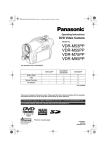
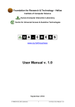
Basic Components
www
R.L
Lighting
.rem
otel
.L.
R.L
i ght
i ngl
ifter
.com
Expansion Bolt
.L.
Lifter
R.L
l i gh
.L.
ting
R.L
lifte
.L.
r@g
mai
Connection Cable for the lLamp
.com
Remote Controller
Diagram for Basic Components
9
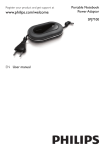
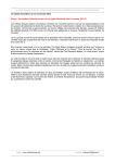
Optional Accessories
Diagram for Optional Accessories
www
.rem
Note: The optional accessories should be conformed to the specifications of connection structure
of ceiling lamp.
R.L
otel
.L.
R.L
i ght
i ngl
ifter
.com
.L.
Connection Part(s)
for the Lamp
R
l
.
i
ghti for the Lamp L.L.
Connection Faceplate
ngl i
R.L
fter@
.L.
gma
il.co
m
Connector
Decoration Cover
10
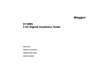
Instruction for Installation
www
.rem
Diagrams for Installation
otel
I. How to connect the upper part of remote lighting lifter (Choose one)
1 The lifter can be installed directly on the ceiling concrete slabs with 4 expansion bolts. This
is suitable for lifter rated load below 150kg.(Diagram 1)
R.L
.L.
R.L
i ght
i ngl
ifter
.com
.LExpansion
.
R.LBolt Bolt
l i gh
.L.
Cushion
ting
Cushion
R.L
lifte
.L.
r@g
Cushionm
ail.c
om
Spring Cushion
Spring Cushion
Nut
Nur
Connector
(Diagram 1)
11
(Diagram 2)
Instruction for Installation
2. There is a fixed connector at the center of the upper cover board with a column drilled an
across hole on the out cylinder. This connector may be connected with the ceiling beam easily.
This is suitable for lifter rated load below 150kg. (Diagram 2)
3. There are four corners at the upper cover board of the lifter which is assembling 4 full
threaded screws. The space between lifter and ceiling is adjustable according to the
sunshade height. This is suitable for lifter rated load below 250kg. (Diagram 3)
www
R.L
.rem
otel
.L.
R.L
i ght
i ngl
ifter
.com
.L.
R.L Bolt
l i gh
.L.
ting
R.L
lifte
.L.
r@g
mai Cushion
l.co
m
Connection Board
Nut
(Diagram 3)
12
Instruction for Installation
II
How to connect the lower part of remote lighting lifter
www
1. The lamp should be linked with the ring at the center of the lower part of the lifter.(Diagram4)
2. The center place of the lower part of the lifter is equipped with a bar. There are 2 screws
and nuts on the bar, which are for center distance adjustment. This connection method is
suitable for the lamp with the weight of less than 50kg. (Diagram 5)
R.L
.rem
otel
.L.
R.L
i ght
i ngl
ifter
.com
.L.
R.L
l i gh
.L.
ting
R.L
lifte
.L.
r@g
mai
l.co
m
Ring
(Diagram 4)
13
(Diagram 5)
Bolt
Cushion
Slide
Connection Bar
Cushion
Nut
Instruction for Installation
3. There is a faceplate at the lower part of the lifter which is provides multi-holes for the bolt
connection. This is suitable for the bigger ceiling mounted. This connection method is suitable
for the lamp with the weight of less than 100kg. The attachment is optional accessories.
(Diagram 6)
www
R.L
.rem
otel
.L.
R.L
i ght
i ngl
ifter
.com
.L.
R.L
l i gh
.L.
ting
R.L
lifte
.L.
r@g
mai
l.co
m
(Diagram 6)
14
Instruction for Installation
III
The requirements and caution of the connection of upper part of the lifter
www
1.0 Tightened with expansion bolt(s). Please refer to Diagram 1.
1.1 All drilled holes should be handled strictly according to the technique requirements on the
{Drilled Hole Specification for Concrete slab 1}. The spare holes are located on the
square board of the lifter for special condition use if there is reinforced when you are
drilling the holes.
Drilled Hole Specification for Concrete Slab-----Table I
R.L
Model
DDJ50
DDJ100
DDJ150
.rem
otel
.L.
R.L
i ght
i ngl
ifter
.com
.
L
.
Specification of
Depth of
R
l
.
i
L.L.Drilled Hole
ghBolt
Expansion
ting
R
lifte
.
(mm)
(mm)
L.L.
r@g
mai Min. 50
M6 X 60
8 x 353 x 90
l.coMin. 50
M6 X 60
8 x 353 x 90
m
Diameter of
Drilled Hole and
Distance of Hole
(mm)
M10 X 100
10 x 390 x 90
Min. 80
Quantity of
Bolts
4
4
4
1.2 Tighten the nuts firmly to ensure the force balance of each bolt. Please refer to Nut
Tightening Force Moment-Table 11 .
15
Instruction for Installation
Nut Tightening Force Moment ---- Table II
Hexagon Head Set Nut (Screw) M5 3.24N/m Note: The performance level of the
nut Grade 5; The performance level of the
Hexagon Head Set Nut (Screw) M6
5.5N/m screw Grade 6.8. Galvanized surface;
The surface should not be coated with
Hexagon Head Set Nut (Screw) M8 15.5N/m grease before tightening and the tightening
force moment should not be lower than
Hexagon Head Set Nut (Screw) M10 26.4N/m the reference data on this table.
www
R.L
.rem
otel
.L.
R.L
i ght
i ngl
ifter
.com
.
L
2.0 Roof beam installation (refer to diagram .2) R
lighin the middle of the lifter,.Lwhich
2.1 There is a connector
is for steel pipe connection. The
.
L
t
.
i
n should
wall thickness of steel pipeg
across
hole on the steel tube is
liftebe more than 3mm. The R
.
L
.L.
drilled based on the bolt diameter. r@
mabei completed by qualified technicians
2.2 The connection of steel pipe and steel beamg
should
l.co
to ensure the connection is reliable.
m
3.0 Connection with 4 long screws (refer to diagram 3)
3.1 Make a square board according to the technique requirement of the attached diagram. The
connection of the square board and steel beam should be completed by qualified
technicians to ensure the connection is reliable.
16
Instruction for Installation
3.2 The lengths of the screws are subject to the size of decoration spaces. Assemble with 4 long
screws to adjust the upper cover board of the lifter in proper level position, then, tighten the
nuts. Please refer to diagram 3.
4.0 Connection reliability test must be applied when completing the upper part installation of
the lifter. The test weight should be 1.5times of the rated load. Lift up the heavy with the
acceptable weight first when testing. (The lifter will not operate when it is overweight)
Please press the key when there is a height of 20mm away from the ground. Then, add
another half as much as the weight and hang it for 5 minutes. The upper part of the lifter is
qualified if it is hung well. You have to recheck the installation process if it is not hung well
when testing until it is qualified.
www
R.L
.rem
otel
.L.
R.L
i ght
i ngl
ifter
.com
.L.
R.L
l i gh
.L.
ting
R.helmet
lifte have to wear the safety
L
Important Warning: The operators
during operation.
.
L
r
@
When the lifter is in use, people should
keep
the distance of at least 2 .meters to stand or
g
ma
pass underneath a load. You have to use the steel
tube which the length is 2m to carry the
il.coheavier. This is to prevent from
heavy by 2 persons when you would like the lifter become
dropping off due to the unqualified concrete slab strength. m
Importance: The lifter must have more than 5kg weight on the steel wire rope on the
installation before start, only then, it may descend. When the lifter is fully earthed, you
have to pay attention to the steel wire rope after releasing the ring to avoid people is hurt.
You have to stretch the steel wire rope first before you carry on the connection testing.
17
Instruction for Installation
IV. The requirements and caution for the connection of the lower part of the lifter and the lamp
1 The attached U-shape ring may be connected firmly to the lamp by the installer. Please refer
to diagram 4. The specifications for the bolts must be accord with the following:
M10 bolt is used for the lamp with the weight of less than 150kg. M12 bolt is used for
the lamp with the weight of less than 150-250kg. The bolts have to accord with the criterion
of Hexagon Head Set Nut (Screw) with Grade C GB/T5780-1986.
2 Place the attached bar into the center screw position for the lower part of lifter by the installer,
then, tighten the bolts and nuts. Move the nut which is slide on the bar to the proper bolt hole
of the lamp. Tighten the screw according to the requirements of Nut Tightening Force
Moment-Table II. Please refer to diagram 5.
3 Assemble the attached faceplate into the center hole position for the lower part of lifter by
the installer, then, tighten the bolts and nuts. Make sure the bolt holes and faceplate slots are
properly in place. Tighten the nuts according to the requirements of Nut Tightening Force
Moment-Table II. Please refer to diagram 6.
4 The decoration cover should be installed after the upper part of the lifter is complete and
qualified before the lower part of the lifter is installed .
www
R.L
.rem
otel
.L.
R.L
i ght
i ngl
ifter
.com
.L.
R.L
l i gh
.L.
ting
R.L
lifte
.L.
r@g
mai
l.co
m
18
Instruction for Installation
V. The connection of power supply and caution
1. Connect the live, neutral and earth wire of the input, supply to the corresponding points
with the voltage of Ac220-240V. Please refer to the diagram 7.
2. You have to connect the power supply and lower conductor of the lifter according to wiring
diagram 8. Please connect the live wire into L1 if the power of the lamp is lower. There are
a lot of live wires when the power of the lamp is higher. Please divide the wires into two
groups and connect them into L1 and L2 separately.
www
R.L
.rem
otel
.L.
R.L
i ght
i ngl
ifter
.com
.L.
R.L
l i gh
.L.
ting
R.L
lifte
.L.
r@g
mai
l.co
m
Wiring Diagram for Power Supply Input
(Diagram 7)
19
Wiring Diagram for Power Supply Output
(Diagram 8)
Instruction for Installation
3. Please make sure the exposed wires which are corresponding to the terminal are properly
in place while you connect the wires so as to prevent them from contacting the metal
conductor surrounding and power leakage.
4. The stamped screws should be tightened and rechecked one by one to ensure the
connection is fixed well when in the process of connection.
www
R.L
.rem
otel
i ght
i ngl
.LAttention
ifterLifter and Lamp
. R to Maintenance between
.com
.L.L
.
ligdroph and lifter stop later, theRlifter
.
L
1. After the lamp
still contains electric, please turn off
.
L
t
.
i
n
R
the switch which control thisglamp,
only
then,
you
may
carry
on .in the maintenance work.
lifte
L.L. metal and so on
r@
2. There are not allow having the wet
water, greasy dirt, coherences
gmain maintenance.
appear at the electric conduction contact face while
i
l.corope while in maintenance.
3. You should keep the tension with 5kg of the steel wire
m
Warning
When the steel wire rope descend too long, it will twist or loop itself and be able to affect
of using the steel wire rope.
20
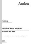
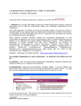
Instruction for Operation
Operation Instruction of Remote Controller
UP Key
www
.rem
Press UP for one second when
the lifter is in the state of stop. The
lifter begins going up.
Press any key for one second
when the lifter is going up. The
lifter stops operating
R.L
.L.
otel
Indicator
DOWN Key
Press DOWN for one second
when the lifter is in the state of stop.
The lifter begins going down.
Press any key for one second
Remote Controller when the lifter is going down. The
lifter stops operating.
R.L
i ght
i ngl
ifter
.com
.L.
R.L
l i gh
.L.
Points to Attention
ting
R.L
l
i
f
t
.ofLRemote
Pull out the antenna when the remoteer
. Controller
@
Battery
Change
controller is in use.
g
ma
l If the indicator becomes dim or is off
l Point the remote controller to the
il.thecopower on, change a new battery.
when
lifter when it is in use.
m
l The effective distance of remote
l If the remote controller is ineffective or is
control is 15m.
l Not allow liquid enter into the remote
controller. To avoid direct sunlight.
Operator
s Instruction
Don t throw
the remote controller.
21
not sensitive, please change the battery.
The battery size is 23A12V.
Instruction for Operation
1. Operation Instruction of Remote Controller
UP : Press UP button on the remote control to raise the steel wire rope. The operation
is ineffective if you press any key to stop within 2 seconds. At this time, the lifter will not
operate.
Test for the upper limit position: The switch of the upper limit position will switch off
and the lifter will stop automatically when the steel wire rope going up until the upper
limit position. At this time, the operation is ineffective if you press UP button again.
DOWN : Press DOWN button on the remote control to descend the steel wire rope.
Press any key to stop it. If the steel wire rope going down to the lower limit position
which you setting before and stop automatically. At this moment, the operation is
ineffective if you press DOWN button again.
2. Memory function setup for lower limit position of remote control (Instruction 2)
Setup the lower limit position of remote control: Press DOWN button on the remote
control to descend the steel wire rope for around 5 seconds when you turn on the lifter.
When the steel wire rope goes down to the required height, please keep press DOWN
button until the lifter stop automatically. After that, please use another hand to press UP
button on the remote control when the steel wire rope goes up a little bit again. Please
release the two buttons when the steel wire rope goes down again. At this moment, the
memory lower limit position of control unit has been set up successfully. If there is other
22
www
R.L
.rem
otel
.L.
R.L
i ght
i ngl
ifter
.com
.L.
R.L
l i gh
.L.
ting
R.L
lifte
.L.
r@g
mai
l.co
m
Instruction for Operation
operation applied suddenly during the steel wire rope going down, the lower limit position
of the wire rope will not be controlled by the main unit memory. At this time, the lower
limit position should be controlled by people. However, the memory lower limit position
of control unit will remain same and auto stop function is still effective when the lifter
goes down next time.
3. Reset memory function for lower limit position of remote control
Cancel the setup: Please keep press DOWN button for around 8-10 seconds and
release it when the lifter has reached its lower limit position. After that, press UP
button on the remote control, the lifter will reached its upper limit position and stop
automatically. At this time, the memory setup has been cancelled.
Renew the setup: The memory datum of the lifter will be renew if you reset it according
to the instruction 2.
4. Function for reset signal code:
Keep press up and down buttons for around 8-10 seconds and release it after the lifter is
electrified within 5 seconds. The lifter will go down if you press 'DOWN' button on the
remote controller. At this time, the instruction for signal code has been reset successfully.
You have to reset the memory function for remote control lower limit position otherwise it
is ineffective.
www
R.L
.rem
otel
.L.
R.L
i ght
i ngl
ifter
.com
.L.
R.L
l i gh
.L.
ting
R.L
lifte
.L.
r@g
mai
l.co
m
23
Instruction for Operation
Warnings!
www
.rem
After the lifter set up the height of lower limit position, the lower limit position of the
lifter will not be controlled by the main unit memory if the artificial operation halts the
lifter suddenly while it is going down. At this time, the lifter should be controlled by
people and you have to pay attention to the safety.
People cut off the electricity suddenly while the lifter is operating and it will cause the
signal code lost and malfunction.
People cut down the heavy until the machine stop suddenly while the lifter is operating
and it will cause the lifter malfunction.
R.L
otel
.L.
R.L
i ght
i ngl
ifter
.com
.L.
R.L
l i gh
.L.
ting
R.L
lifte
.L.
r@g
mai
l.co
m install the remote lighting
The installers have to read the instruction manual carefully before
lifter. Please contact us for further information if any problem or query.
Email: [email protected] Tel: 0086-592-8067637
24
Three Commitments
We perform three commitments: repair, replace and refund. According to the relevant
stipulation in Protection Law for Consumer s Rights and Interest, our company will provide
you the service based on your warranty card and purchase invoice.
1. This product is fully-warranted against defective materials and manufacturing fault for a
period of 12 months from the date of purchase.
2. Examples of the foregoing, but without limitation are:
a. Products damaged during installation or incorrect method of installation or poor
installation or improper transportation done by unqualified personnel.
b. The damage occurred is due to the disassembly by the users or the repair agents
non-appointed by our company.
c. The users alter the information of purchase invoice or there is no warranty card and
purchase invoice when servicing is required.
d. Damage as a result of fire, flood, abnormal voltage, or natural disaster.
e. The damage occurred due to alteration in any way to the product by any unauthorized
technician or improper operation.
f. The damage occurred is due to the irresistible factors.
3. We are pleased to provide you the whole life service even if it is not the free-charge
service items.
Please keep the warranty card and purchase invoice properly. The warranty
period is subject to the issuing date of the purchase invoice.
www
R.L
.rem
otel
.L.
R.L
i ght
i ngl
ifter
.com
.L.
R.L
l i gh
.L.
ting
R.L
lifte
.L.
r@g
mai
l.co
m
25
www
WARRANTY CARD
.rem
otel
No: 0000001
Telephone No.
i
g
h
R.L
t
i
n
g
.
lifte
L
.
Address
r.co
R.L
m
.
L
.
Product Modell
of Purchase
R.Date
i ght
L
.
L
.
i
n
g
Product No.
InvoiceR
No.
lifte
.
L.L.
r@g
maTelephone
Sales Agent
il.co No.
m
User s Name
Remark
26
www
WARRANTY CARD
.rem
otel
No: 0000001
Telephone No.
i
g
h
R.L
t
i
n
g
.
lifte
L
.
Address
r.co
R.L
m
.
L
.
Product Modell
of Purchase
R.Date
i ght
L
.
L
.
i
n
g
Product No.
InvoiceR
No.
lifte
.
L.L.
r@g
maTelephone
Sales Agent
il.co No.
m
User s Name
Remark
27
www
.rem
Good Husband
ote Lighting Lifter
l i gh
R.L
ting
l
.LCleaning
. R Simple andiftConvenient
Makes
er.
l i gh
.L.L
.
ting
l
R.L
com
.L.
R.L
ifter
.L.
@g
mai
l.co
m
Add: Maofu, Xiayang Industry Area, Houmao Community, Fujian Province China
Tel: 86-592-8067637
E-mail: [email protected]
PC: 362000
Http://www.remotelightinglifter.com
28