1
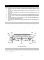
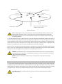
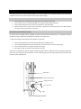
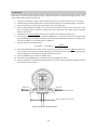
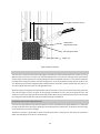
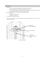
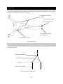
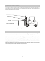
Infini-T™ Recoiling System Operator’s Manual & Installation Guide September 2015 AC03-UserMan WARRANTY Technical Systems extends a 5 (five) year warranty for the Infini-T™ Recoiling system against all defects arising from faulty workmanship or materials during the aforesaid periods, commencing on the date of delivery to the customer. The warranty does not apply to damage caused by normal wear and tear over time, or for defects and damage arising after the guarantee periods referred to above. Any attempt to alter, dismantle or change the standard specifications of the product will render this warranty null and void. This warranty does not cover consequential damages and/or loss of or damage to products due to negligence or misuse. This warranty is made to the original purchaser of the product and is not transferable. The warranty obligation, including defects liability arising from faulty workmanship, is subject to our standard Terms and Conditions. Conditions & Limitations The product must be installed by and operated in accordance with the instructions as provided by the manufacturer or the warranty will be void. The Warranty will be void if all components of the Infini-TTM Recoiling system are not original equipment supplied by the manufacturer. Malfunctions or failure resulting from misuse, abuse, negligence, alteration, accident, or lack of proper maintenance or a failure to comply with the conditions of sale shall not be considered defects under the warranty and will be excluded. This warranty applies only to systems for the care of poultry, pig and livestock. Any other applications of our products and systems are not covered by this warranty. The warranty for the Infini-T TM Recoiling system applies only when used together with a Technical Systems Infini-TTM Auger mothercoil in terms of the manual, instructions or specifications supplied by Technical Systems. In the event of the mothercoil being used with another recoiling system, this warranty will only cover the mothercoil if such other recoiling system has been approved by a representative of Technical Systems prior to or on installation of the mothercoil and system by the customer. Technical Systems shall not be liable for any consequential or special damage which any purchaser may suffer or claim to suffer as a result of any defect in the product. Consequential or special damages as used herein include, but are not limited to, lost or damaged products or goods, costs of transportation, lost sales, lost orders, lost income, increase overhead, labour and incidental costs and operational inefficiencies. i TABLE OF CONTENTS Warranty .................................................................................................................................................................. i Introduction ............................................................................................................................................................ 1 System overview ..................................................................................................................................................... 2 The Infini-T™ Mothercoil ........................................................................................................................................ 3 Basics of coiling auger............................................................................................................................................. 5 Determining a coil’s length ................................................................................................................................ 6 Selecting a coil’s diameter .................................................................................................................................. 6 Wiring of a coil ................................................................................................................................................... 8 Making the auger safe for handling ................................................................................................................... 9 Decoiler................................................................................................................................................................. 10 Safety checks .................................................................................................................................................... 10 Loading the pallet ............................................................................................................................................. 10 Positioning the cover ........................................................................................................................................ 10 Adjusting the brake .......................................................................................................................................... 11 Uncoiling the mothercoil .................................................................................................................................. 12 Working with heavy mothercoils ..................................................................................................................... 12 Maintenance .................................................................................................................................................... 12 Length counter ..................................................................................................................................................... 13 Safety checks .................................................................................................................................................... 13 Adjusting the opening height ........................................................................................................................... 13 Calibration ........................................................................................................................................................ 14 Maintenance .................................................................................................................................................... 15 Coiler..................................................................................................................................................................... 16 Overview .......................................................................................................................................................... 16 Safety checks .................................................................................................................................................... 17 Coiling the auger .............................................................................................................................................. 17 Setting desired length ...................................................................................................................................... 18 Adjusting the mandrel ...................................................................................................................................... 19 Running the coiler ............................................................................................................................................ 19 Operating the coiler arm .................................................................................................................................. 20 Stopping the coiler and decoiler ...................................................................................................................... 20 Maintenance .................................................................................................................................................... 21 Coil Lifter............................................................................................................................................................... 22 Attaching coil lifter to an overhead crane ........................................................................................................ 22 Attaching coil lifter to a forklift ........................................................................................................................ 23 Using the coil lifter ........................................................................................................................................... 23 System installation ............................................................................................................................................... 24 Floor plan layout and fixing points ................................................................................................................... 24 Electrical connections ...................................................................................................................................... 24 Connecting the power supply ...................................................................................................................... 25 Connecting the length counter .................................................................................................................... 25 Connecting the decoiler brake ......................................................................................................................... 25 Appendix A: Wiring diagram ................................................................................................................................. 27 Appendix B: Length Counter Parameters ............................................................................................................. 28 Appendix C: Changing the Coiler Speed ............................................................................................................... 29 INTRODUCTION In support of our world-leading Infini-T auger products, which allow our customers to cut the desired auger lengths at their own premises, Technical Systems also developed the machinery to handle the decoiling, measuring and coiling of the auger, known as the Infini-T Recoiling System. This document serves as a user manual for the Infini-T Recoiling System and aims to provide users with all the information necessary to run the system. However, it is strongly advised that you watch the demonstration video on our website, www.technicalsys.com for more clarity on the operation of the Infini-T Recoiling System. 1 SYSTEM OVERVIEW The Infini-T™ Recoiling System consist out of three units and a handling tool namely: Decoiler The pallet with the Infini-T mothercoil as ordered from Technical Systems is placed on this machine, which allows the entire pallet to rotate. Length counter This unit is used to measure the length of the auger being coiled to ensure that the correct lengths are consistently produced. Coiler This unit is motorised and is used to recoil auger into new, shorter auger coils with different coil diameters. Coil Lifter This tool is designed for easy handling of auger coils using either a forklift or an overhead crane. (shown without chains and hooks.) 2 THE INFINI-T™ MOTHERCOIL When shipped from Technical Systems the Infini-T mothercoil will be packaged as shown in Figure 1. Since the auger is truly continuous (without any welds or brazing), it has to be layered as it is wound onto a spool. The first layer is coiled in an upwards direction until the spool is full. Wire is then looped from the inside of the coil to the outside and tightened in six places around the coil (see page 8 for more detail). This layer is then wrapped with a carton sheet before starting the second layer. The second layer is coiled in a downwards direction until the spool is full and then also fixed with wire and wrapped with carton. This process is repeated for each layer, with the direction of the coiling alternating between the layers. Hence, when the mothercoil is decoiled, the six wire loops on each layer should be removed along with the carton sheeting. Figure 1: The Mothercoil (Cross-sectional view) 3 Note that with some layers the auger will uncoil from the bottom up, resulting in some layers sliding down, but this should not be a cause for concern. If decoiling is stopped midway, simply wrap the remaining piece of auger back onto the coil and use wire to secure the loose end to the auger itself. The mothercoil is shipped with a steel inner core that is strapped to the pallet with BLUE strapping. This is to ensure that the coil does not slide off the pallet or falls over. It also serves to maintain the integrity of the coil when uncoiling so that coil does not collapse, especially at the last layers. Therefore it is extremely important to check that the core is still securely fixed to the pallet with the BLUE strapping when handling or decoiling the mothercoil. The entire mothercoil will be strapped before shipping with GREEN strapping. When removing packaging these GREEN straps should be removed, but take care not to cut the BLUE strapping that fixes the steel core to the pallet. Take care not to cut the BLUE strapping that keeps the steel core fixed to the pallet when removing packaging! 4 BASICS OF COILING AUGER To easily understand the principles of recoiling auger, it is necessary to introduce some basic concepts first. Please take special note of the terminology used in this chapter as these will be used throughout the manual. An auger, also known as a helicoid or spiral, is made of flat wire and is characterised by its outer diameter (OD), inner diameter (ID) and pitch (see Figure 2 below). Pitch ID OD Length Figure 2: Auger characteristics When a long length of auger is rolled into a coil for packaging and shipping, this coil is also characterised by a coil ID, a coil OD and a coil height. This is achieved by wrapping the auger around a core/pipe with a diameter equal to the desired coil ID. Each layer of auger is placed on top of the previous layer, forming a coil with a coil height as shown in Figure 3. Number of pitches on coil diameter Number of vertical layers Coil Height Coil ID Coil OD Figure 3: Auger coil characteristics By having coils with different IDs, smaller coils can be placed inside larger coils to maximise packaging space. The coils can also be stacked on top of each other. This means one can have multiple stacks of coils inside each other on a single pallet, as shown in Figure 4. 5 Inner coil stack Middle coil stack Fourth coil Third coil Second coil Outer coil stack First coil Pallet Figure 4: Stacking multiple coils inside each other DETERMINING A COIL’S LENGTH When an auger is rolled into a coil, the length of the auger can be calculated by multiplying the following: 𝐴𝑢𝑔𝑒𝑟 𝑙𝑒𝑛𝑔𝑡ℎ = (𝐴𝑢𝑔𝑒𝑟 𝑝𝑖𝑡𝑐ℎ) × (𝑁𝑢𝑚𝑏𝑒𝑟 𝑜𝑓 𝑝𝑖𝑡𝑐ℎ𝑒𝑠 𝑎𝑟𝑜𝑢𝑛𝑑 𝑑𝑖𝑎𝑚𝑒𝑡𝑒𝑟 𝑜𝑓 𝑐𝑜𝑖𝑙) × (𝑁𝑢𝑚𝑏𝑒𝑟 𝑜𝑓 𝑣𝑒𝑟𝑡𝑖𝑐𝑎𝑙 𝑙𝑎𝑦𝑒𝑟𝑠 𝑜𝑛 𝑐𝑜𝑖𝑙) For example, if the auger has a pitch of 50mm and the coil has 62 pitches around the diameter and 20 vertical layers, the length of auger on the coil is: 50𝑚𝑚 × 62 × 20 = 62000𝑚𝑚 = 62𝑚 SELECTING A COIL’S DIAMETER Since auger has a fixed pitch, it cannot be wrapped around any diameter. The diameter of the coil has to be calculated in increments of the auger’s pitch. To calculate a coil’s ID, the following formula should be used: 𝐶𝑜𝑖𝑙 𝐼𝐷 = 𝑛 × 𝑃𝑖𝑡𝑐ℎ − 𝐴𝑢𝑔𝑒𝑟 𝑂𝐷 3.14 In this formula, 𝑛 is the number of pitches around the coil diameter and can only be a whole number (e.g. 1, 2, 50, 51) and not a fraction of a number (e.g. 1.2, 3.8). For example, if an auger has a pitch of 50mm, an OD of 69mm and there are 62pitches around the coils’ diameter, the coil ID will be: 6 𝐶𝑜𝑖𝑙 𝐼𝐷 = 62 × 50𝑚𝑚 − 69𝑚𝑚 = ±918𝑚𝑚 3.14 However, in most cases one would need to know the number of pitches necessary in order for the auger coil to have a certain ID: 𝑁𝑢𝑚𝑏𝑒𝑟 𝑜𝑓 𝑝𝑖𝑡𝑐ℎ𝑒𝑠 = 3.14 × (𝐶𝑜𝑖𝑙 𝐼𝐷 + 𝐴𝑢𝑔𝑒𝑟 𝑂𝐷) 𝑃𝑖𝑡𝑐ℎ For example, if a coil ID of 750mm is required for the same auger as above (pitch 50mm, OD 69mm), the number of pitches are calculated as: 𝑁𝑢𝑚𝑏𝑒𝑟 𝑜𝑓 𝑝𝑖𝑡𝑐ℎ𝑒𝑠 = 3.14 × (750 + 69) = 51.433 50 Since a fraction of a pitch cannot be used, the number is rounded up to 52 pitches, ensuring that the coil ID will not be smaller than 750mm. In this case the actual coil ID will be ±759mm. Finally, should it be required to calculate the coil OD, the following formula can be used: 𝐶𝑜𝑖𝑙 𝑂𝐷 = 𝑛 × 𝑃𝑖𝑡𝑐ℎ + 𝐴𝑢𝑔𝑒𝑟 𝑂𝐷 3.14 Table 1 provides a quick summary of the formulas discussed: Table 1: Summary of auger coil formulas Coil length 𝑨𝒖𝒈𝒆𝒓 𝒍𝒆𝒏𝒈𝒕𝒉 = (𝑨𝒖𝒈𝒆𝒓 𝒑𝒊𝒕𝒄𝒉) × (𝑵𝒖𝒎𝒃𝒆𝒓 𝒐𝒇 𝒑𝒊𝒕𝒄𝒉𝒆𝒔 𝒂𝒓𝒐𝒖𝒏𝒅 𝒅𝒊𝒂𝒎𝒆𝒕𝒆𝒓 𝒐𝒇 𝒄𝒐𝒊𝒍) × (𝑵𝒖𝒎𝒃𝒆𝒓 𝒐𝒇 𝒗𝒆𝒓𝒕𝒊𝒄𝒂𝒍 𝒍𝒂𝒚𝒆𝒓𝒔 𝒐𝒏 𝒄𝒐𝒊𝒍) Coil ID 𝐶𝑜𝑖𝑙 𝐼𝐷 = 𝑛 × 𝑃𝑖𝑡𝑐ℎ − 𝐴𝑢𝑔𝑒𝑟 𝑂𝐷 3.14 Coil OD 𝐶𝑜𝑖𝑙 𝑂𝐷 = 𝑛 × 𝑃𝑖𝑡𝑐ℎ + 𝐴𝑢𝑔𝑒𝑟 𝑂𝐷 3.14 Number of pitches on coil diameter 𝑁𝑢𝑚𝑏𝑒𝑟 𝑜𝑓 𝑝𝑖𝑡𝑐ℎ𝑒𝑠 = 7 3.14 × (𝐶𝑜𝑖𝑙 𝐼𝐷 + 𝐴𝑢𝑔𝑒𝑟 𝑂𝐷) 𝑃𝑖𝑡𝑐ℎ WIRING OF A COIL When a coil has been successfully completed it must be secured with wire to ensure that it does not become undone during handling and shipping. It is suggested that 2mm Black baling wire is used for this purpose. Firstly, fasten the loose ends of the coil to the coil itself using wire. Then, while the coil is still on the mandrel, add wire loops at six positions on the coil as shown in Figure 5. Fix with wire six positions Figure 5: Wire fixing positions To securely fasten the wire, follow these steps: 1. 2. 3. 4. 5. 6. 7. Cut a piece of wire double the length required for one loop Fold this length in half Now loop the folded wire around the coil as shown in Figure 6. Tie the loose ends of the loop together. At this stage the wire loop will not be very tight. Use the tool supplied to tighten the loop around the coil by grabbing the loop with the hook of the tool and then twisting the wire. Bend all sharp ends of the wire away so that they cannot cause harm. Repeat this at the six positions as shown in Figure 5. 8 Secure loose ends first Quarter view of auger coil Use tool to twist wire until it is tight Wire loop (one piece of wire folded in half) Figure 6: Cross-sectional view of coil with wire loop MAKING THE AUGER SAFE FOR HANDLING When the auger is cut, the ends of the flat wire might be very sharp and could be hazardous. It is therefore advised to ensure that the flat wire ends are filed to remove any sharp edges or points. Furthermore, even if the flat wire ends have been smoothed, it is still advised to fit a small piece of tubing over the wire so that it extends beyond the end of the wire. 9 DECOILER SAFETY CHECKS 1. 2. 3. 4. 5. 6. 7. Ensure that the core of the mothercoil is still securely fixed to the pallet as this could detach during shipping. Ensure that there is no debris underneath the decoiler that can get caught and/or wound up around the machine. Ensure that there is nothing lying on the turntable (see Figure 7) that can be thrown off when the decoiler spins. Ensure that the brake is fully operational and correctly adjusted. (See: Adjusting the brake on page 11) Ensure that the pallet is loaded correctly and presses against the back of the rail guides (See: Loading the pallet.) Ensure that the bolts fixing the decoiler to the ground are intact and properly tightened to avoid the machine from sliding or tilting during operation. To avoid risk of injury, ALWAYS ensure that no part of the body is underneath the turntable when it is turning. LOADING THE PALLET When loading the pallet, rotate the decoiler so that the open ends of the pallet guides are facing towards the loading side. DO NOT ACTIVATE THE BRAKE DURING LOADING to ensure that the pallet guides itself into position. Slide the pallet into the pallet guides ensuring that the bottom planks of the pallet are under the pallet guides with the pallet positioned on the turntable. Slide the pallet into the guides until it stops against the back of the guides. The pallet is now loaded and ready for decoiling. Figure 7 shows the decoiler with the pallet loaded in the correct position. Pallet guides Pallet Turntable Figure 7: Pallet position on decoiler POSITIONING THE COVE R The cover is an integral part of the decoiler as it prevents the mothercoil’s ID from collapsing and prohibits the auger from “climbing over” the coil during decoiling. It is important that the cover is placed in position BEFORE starting the decoiling operation. 10 Adjustment knob Lifting point Note: Cover shown with ID locators moved to centre of cover. Coil ID locators Figure 8: Decoiler cover Before positioning the cover on the mothercoil, check that the steel core of the mothercoil is still securely fixed to the pallet. There is a risk that the core can become detached from the pallet during shipping. If the core is not securely fixed to the pallet, the mothercoil may fall over during the uncoiling process! To correctly position the cover on the mothercoil, all the coil ID locators should first be moved to the centre of the cover by loosening the adjustment knobs (see Figure 8) until the locator can slide into its groove. Slide the locator towards the centre of the cover and fasten the adjustment knobs. Using a forklift or an overhead crane, position the cover on top of the mothercoil. The lifting point on the cover is designed to fit a single fork of the forklift. Try and position the cover as close as possible to the centre of the mothercoil. Once the cover is in position on top of the mothercoil, readjust the ID locators by sliding them outwards until they all touch the inside edges of the mothercoil. All ID locators should ideally be located an equal distance apart, which indicates that the cover is positioned in the middle of the mothercoil. ALWAYS ensure that the cover is correctly positioned and that the ID locators are pressed against the mothercoil’s ID. As the cover is not fixed to the mothercoil, incorrect placement can cause the cover to fall off during operation. NEVER transport or move the coil with the cover on. Remove the cover before moving the mothercoil. ADJUSTING THE BRAKE It is important to check that the brake is properly adjusted. If the brake is too tight, the coiler will have difficulty uncoiling the auger which will result in unnecessary tension in the auger. If the brake is too loose, it will not engage quickly enough when the operator presses the brake pedal with the result that the mothercoil will keep spinning even after the coiler has stopped, causing the auger to unwind itself and possibly get tangled. NOTE: Be careful not to rotate the decoiler while your hands are underneath the turntable to avoid risk of injury! 11 To adjust the braking force, turn the adjustment nut under the decoiler as shown in Figure 9. It is important to note that the brake cable will stretch over time, especially in the beginning and should therefore be checked often. Brake arms Adjustment nut Figure 9: Decoiler brake adjustment UNCOILING THE MOTHER COIL The auger mothercoil is made up of layers of auger wound over each other, each layer separated by carton sheets. Each layer is also individually strapped with wire at four points per layer to prevent the mothercoil from collapsing during shipping. It also reduces the risk of the auger becoming tangled when uncoiling. When the mothercoil is being decoiled, the operator should take care to stop the process at the end of each layer to first remove the carton sheets and the wire strapping. Failure to do so could result in the mothercoil falling over. WORKING WITH HEAVY M OTHERCOILS When working with smaller mothercoils, the coiler will have enough power to turn the decoiler. When a heavy mothercoil is loaded, however, the coiler will not be able to start turning the decoiler and mothercoil on its own and a second operator is required to manually help turning the mothercoil when the coiling process is started. The coiler will be able to maintain the rotation once up to speed. MAINTENANCE Adjust brake tension Check all bolts ensuring that they are tight. Check main bearing under turntable to ensure it is still functioning properly. Check bearings supporting the turntable Check wear on brake liners 12 LENGTH COUNTER The length counter uses a simple bicycle wheel to run over the auger as it is pulled through the unit. With proper calibration this unit is accurate to within 0.5% of the required length. SAFETY CHECKS 1. 2. 3. 4. Ensure that there is nothing that can get stuck in the spokes of the wheel. Ensure that the unit is correctly adjusted for the specific auger being measured. Ensure that the wheel is free to move up and down on the slide pillars. Always ensure that no-one is near the unit when in operation to avoid risk of injury. The wheel spokes can cause serious injury when in operation. ADJUSTING THE OPENING HEIGHT To ensure that the length counter provides accurate and consistent measurements, it is important that the height of the upper guide shoe is adjusted correctly for each auger type. To adjust the height, following these steps (Refer to Figure 10): 1. 2. 3. 4. Lift the upper guide shoe by hand and feed the auger through the unit. Turn the height adjustment knob until the shoe is no more than 0.5 mm from the auger. Ensure that the wheel is making contact with the auger. Pull auger through and check that the wheel is turning. NOTE: If it is too difficult to pull the auger through the length counter, slightly increase the height of the upper guide shoe by turning the knob clockwise. Do not allow the gap to be too big otherwise this will affect the accuracy of the measurement. Slide-pillars Height adjusting knob Upper guide shoe Gap = ±0.5mm Max 0.5mm Auger Figure 10: Adjusting upper guide shoe 13 CALIBRATION If the unit is not measuring the lengths correctly, it might be necessary to calibrate the length counter. This is done as follows with reference to Figure 11: 1. 2. 3. 4. Take a 12 m long piece of auger, measure exactly 10 m from one end and make a mark on the auger. Feed this auger into the length counter until the end of the auger is in line with the auger’s “Zero point”. On the control box, press the length reset button until zero is displayed. Pull the auger through the length counter by hand and stop when the 10 m mark reaches the “Zero point”. Do not go past the “Zero point” and try to line up the 10 m mark on the auger as close as possible with the “Zero point”. 5. Write down the measured length shown on the counter control display (see Figure 12). 6. On the counter control box, press and hold the MODE key for 3 seconds until FUnC is displayed. Now press the MODE key until PSCALE is displayed. Write down the PSCALE value shown on the display. This will now be called the “old” PSCALE value, or PSCALE old. 7. Now calculate the new PSCALE value: 10000 𝑃𝑆𝐶𝐴𝐿𝐸𝑛𝑒𝑤 = 𝑃𝑆𝐶𝐴𝐿𝐸𝑜𝑙𝑑 × 𝑀𝑒𝑎𝑠𝑢𝑟𝑒𝑑 𝐿𝑒𝑛𝑔𝑡ℎ 8. Enter the new PSCALE value on the counter using the Up and Down arrow keys. (TIP: The Left key can also be used to move left by one digit, allowing the selected digit to be changed. The digit will flash when selected and can be adjusted using the Up and Down keys.) 9. Press the MODE key to save the new PSCALE value 10. Press and hold the MODE key for 3 seconds to exit the configuration mode 11. Check if calibration is successful by repeating steps 1 to 3. If the measured length is displayed correctly the calibration was successful. Auger OUT Auger IN (To coiler) (From decoiler/mothercoil) Auger calibration “Zero point” Figure 11: Zero point for calibration purposes 14 Length counter control box Counter Measured length (Actual length), shown in RED Set length (Desired length), shown in GREEN Mode key Left key Up/Down keys Length Reset button Coiler direction knob Figure 12: Length counter unit control box MAINTENANCE This unit requires little maintenance. However, periodic checks are advisable to ensure that: The wheel spins freely The up/down movement of the wheel is smooth and easy. Lubricate if necessary. All bolts are still securely fastened. The tyre surface is not worn Should the unit not function properly, check that all the parameters of the DELTA CTA4 counter are still set correctly. Details on these parameters can be found in Appendix B. For more information and the manual on the DELTA CTA4 unit, please refer to their website: http://www.deltaww.com/ 15 COILER OVERVIEW SPECIAL NOTICE: THE COILER IS A POWERFUL MACHINE THAT CAN CAUSE SERIOUS BODILY HARM IF NOT OPERATED CORRECTLY. The operator of this machine must at all times adhere to the guidelines stated in this manual. To avoid harm to others always ensure that no-one except the operator is near the machine when it is operated. Since this machine is the driving force of the entire recoiling line, special care should be taken to ensure that all other parts of the recoiling line (decoiler and length counter) are safe to operate before starting the coiler. Mandrel diameter Adjustment spanner (Removable) Mandrel Auger inlet Control box Coiling arm Forward Brake pedal for decoiler Coiler accelerator pedal Figure 13: Coiler 16 SAFETY CHECKS 1. 2. 3. 4. 5. 6. 7. Is the decoiler ready for operation? Is the length counter ready for operation? Has the adjustment spanner been removed? Check that there is nothing on the machine that can become undone or fall off during operation. Has the correct direction been selected? Ensure that the bolts fixing the coiler to the ground are intact and properly tightened to prevent the machine from sliding or tilting during operation. To avoid risk of injury, ALWAYS ensure that no part of the body is underneath the turntable when it is turning. COILING THE AUGER The process of coiling the auger is described below. Some of the steps are explained on the assumption that all the previous sections have been read: 1. 2. 3. 4. 5. 6. 7. 8. 9. 10. 11. 12. 13. 14. 15. 16. 17. Adjust the mandrel (page 19) to a smaller diameter than the required coil diameter. (For details on selecting the coil diameter, please refer to page 6) After the decoiler has been properly set up and the length counter is ready and calibrated, feed the auger through the inlet (Figure 14). Enter the desired length on the control box. (see page 18) Keep the end of the auger at the cut-off point and then reset the length counter to zero by pressing the RESET button. Continue to pull the auger through the inlet and wrap around the mandrel as shown in Figure 14. Count the number of pitches around the mandrel and fix the auger to itself at the preselected number of pitches. Now slowly increase the mandrel diameter until the auger starts turning with the mandrel, then stop immediately. Remove the adjustment spanner from the coiler mandrel Place the coiler arm in position (page 20) Start the coiling process (page 19) During coiling, take care to stop in time to remove the packaging and wiring between layers on the mothercoil. (seeUncoiling the mothercoil on page 12) The coiler will stop automatically once the set length is reached. Use the brake pedal to stop the decoiler. The coiling arm can be removed at this stage. Cut the auger at the cut-off point and fix the loose end to the coil. Now increase the mandrel diameter to tighten the coil. This will ensure that the coil meshes neatly and evenly. Do not overtighten the coil! Use wire to strap and tighten the coil at six positions. (see page 8.) Decrease the mandrel diameter so that the coil can be removed easily (page 19) You can now remove the coil using the coil lifter. (see page 23) 17 Wrap auger around mandrel as indicated Auger inlet From Length Counter Cut-off point Figure 14: Setting up the coiler SETTING DESIRED LENG TH The length counter is programmed to stop the coiler once a certain length has been reached. It is also programmed to slow down the coiler before stopping to reduce the risk of an overrun. To enter a length, use the UP and DOWN keys. (TIP: The Left key can be used to move left by one digit, allowing the selected digit to be changed. The digit will flash when selected and can be adjusted using the Up and Down keys.) Before starting the coiling process, the operator should first enter the desired length as follows: 1. 2. 3. 4. Press the Mode key until SET2 is shown on the display. Enter the desired length. (The coiler will stop at this length.) Press the Mode key until SET1 is shown on the display. Enter the desired length MINUS 1 meter. (The coiler will slow down at this length.) NOTE that the length counter uses millimetres (mm). (For example, if an auger length of 52.5 m is required, the length should be set at 52 500 mm.) Since there is a 0.5% accuracy on the length counter, it is advised to accommodate for this error when coiling the auger to a required minimum length. For example: If the minimum length of the auger should be 100m, set the desired length (SET2) to 100.5m (100m + 0.5%). This means that the SET1 parameter should be set to 99.5m (100.5m - 1m). 18 ADJUSTING THE MANDRE L When an auger is to be coiled to a specified internal diameter (ID), the mandrel should first be set to a smaller diameter than said ID. This will ease the initial wrapping of the auger around the mandrel to the correct diameter. Follow these steps to adjust the mandrel: 1. Insert the adjustment spanner onto the hexagonal shaft on top of the mandrel NOTE: Take special care when the adjustment spanner is used to adjust the mandrel. If the spanner is not held stationary while the mandrel is turning, it will turn with the mandrel and can cause serious bodily harm. NEVER leave the spanner attached to the mandrel without holding on to the spanner! 2. To decrease the mandrel’s diameter, keep the spanner stationary and run the coiler backward. To increase the mandrel’s diameter, run the coiler forward while keeping the spanner stationary. 3. When the desired diameter is reached, stop the coiler and remove the spanner. NEVER attempt to insert or remove the spanner into the mandrel socket while the mandrel is turning! To protect the machine and the operator from harm, take special care when adjusting the mandrel to its maximum or minimum diameter. If the maximum or minimum diameter is reached, the spanner will turn with the mandrel, potentially causing harm. RUNNING THE COILER The coiler is fitted with a control box with a direction knob (see Figure 12 in the previous section). To turn the coiler in the forward direction, turn the knob to FORWARD while the coiler is stationary. DO NOT switch between FORWARD and BACKWARD while the coiler is turning! When the operator is ready, press the accelerator pedal (see Figure 13) to start turning the coiler in the selected direction. The coiler is programmed to start slowly and then increase steadily to its maximum speed. This has been deliberately programmed into the motor drive to avoid personal injuries or damage to the machines. Should it be desired to change the running speed of the coiler, please refer to Appendix C for further instructions. 19 Minimum clearance ±2mm Guide plate adjustment knobs Vertical guide plate Auger coil Figure 15: Coiler arm operation OPERATING THE COILER ARM The coiler arm is used to help wrap the auger tightly and neatly around the mandrel while the mandrel is turning. Before coiling commences, the coiler arm should be adjusted to fit correctly over the auger being coiled. When smaller augers are being coiled, the vertical guide plate should be adjusted to allow a ± 2 mm clearance between the edge of the coiling arm and the mandrel (see Figure 15). It can be adjusted by turning the two knobs on the arm. Always ensure that the side guide plate is adjusted evenly and that it remains parallel with the coiler arm. An uneven guide plate will impair the coiling performance. When the auger is wrapped around the mandrel and the operator is ready to commence with coiling, place the arm onto the auger as shown in Figure 15. By applying a steady force on the arm at the position and in the direction as shown, the auger should mesh into itself neatly. When coiling is completed, the arm can be removed by pulling it towards the operator and then steadily lowering it downwards. STOPPING THE COILER AND DECOILER The coiler is programmed to stop when the operator’s foot is removed from the pedal. However, it is important to stop the decoiler from spinning by stepping on the brake pedal. If the decoiler is not braked in time the auger on the mothercoil can become tangled. Therefore it is always a good habit to press the brake pedal when removing one’s foot from the accelerator pedal until everything has come to a complete stop. 20 MAINTENANCE Lubrication o The main bearing under the turntable should be greased every 6 months o The drive chain should be lubricated with a suitable chain lubricant o The scroll shaft (see Figure 16) in the centre of the mandrel should be lubricated with a moly grease o The slide shafts (see Figure 16) should be lubricated with grease Check the following for excessive wear and tear and replace if necessary: o Brake liners o Castor wheels under turntable o Guide plates on coiling arm All bolts should be checked for tightness. NOTE that the linkage bolts on the mandrel (Figure 16) should not be overtightened as this will impair the operation of the mandrel. Linkage bolts (Do not overtighten!) Slider shafts (x6) Scroll shaft (Lubricate with moly grease) Figure 16: Coiler mandrel 21 COIL LIFTER The coil lifter is used to securely remove an auger coil from the coiler without damaging the coil. The coil lifter can either be used with a forklift or with an overhead crane with different mounting holes on the coil lifter depending on the application as shown in Figure 17. Brackets to fit fork of forklift To fit triple chain sling for overhead crane To suspend chains (x3) for lifting auger To fit forklift safety chain Figure 17: The coil lifter ATTACHING COIL LIFTER TO AN OVERHEA D CRANE To attach the coil lifter to an overhead crane, a triple chain sling with the required load rating should be attached as shown in Figure 18. Overhead crane hook Triple chain sling Coil lifter Chains for lifting auger Figure 18: Attaching to an overhead crane 22 ATTACHING COIL LIFTER TO A FORKLIFT The coil lifter can also be used with a forklift. The lifting point is designed to fit a single fork of the forklift. To prevent the coil lifter from sliding off the fork, it is imperative that the safety chain is securely attached to the backrest of the forklift as shown in Figure 19. Forklift backrest Safety chain Coil lifter Chains for lifting auger Figure 19: Attaching the coil lifter to a forklift USING THE COIL LIFTE R Before a coil is removed from the coiler ensure that the ends of the auger are fastened to the coil using wire. The coil itself should also be securely fastened with wire as described on page 8 (Wiring of a coil). Next, reduce the diameter of the coiler mandrel just enough so that the coil can be easily pulled off the mandrel. Position the coil lifter over the coil with the three chains hanging over the outside of the coil. Hook the chains to the underside of the coil, then lift the coil lifter slightly to put tension on the chains. Now check that all three hooks have hooked onto the coil securely before proceeding with lifting the coil off the mandrel. Take special care to try and keep the coil lifter over the centre of the mandrel. If the coil lifter is off-centre, the coil will start swaying as it leaves the top of the mandrel. Always ensure that the chains are the same length and that the coil is lifted evenly. Failure to do so could result in the coil falling from the coil lifter and possibly causing serious harm. 23 SYSTEM INSTALLATION FLOOR PLAN LAYOUT AND FIXING POINTS Shown in Figure 20 is the floor plan of the system once installed. Note that the auger should ideally run in a straight line from the decoiler, through the length counter and then through the coiler inlet. The system will still function even if these three elements are not completely aligned, but the layout shown below would yield optimum results. Figure 20: Floor plan Please note the following when allocating an area for installing the recoiling line: The floor layout in Figure 20 does not account for space for the operator to move around the units. It is advised that there should be at least 800mm space around the units for ease of access. To be able to remove the auger coils from the coiler, the height of the ceiling above the coiler should be a minimum of 6 m. The system is designed to be installed on a concrete floor. All three units must be securely bolted to the floor using the anchor bolts supplied with the machines. The conduit pipes should also be fixed to the floor using the saddles provided to protect the cables and to prevent the risk of somebody tripping over the loose cables. ELECTRICAL CONNECTION S NOTE: All electrical connections and commissioning should be done by a qualified electrician as per the regulations of the country concerned. The machine is shipped with all the internal wiring in place. The only remaining connections that need to be done on-site is for the power supply and the length counter control box. 24 CONNECTING THE POWER SUPPLY The system has to be connected to the power supply inside the electrical panel box which is situated underneath the coiler. On the side of the panel there is an unused compressions lug which can be used to feed the power supply cable into the box where it can be connected. Please refer to the wiring diagrams in Appendix A when connecting the power cable. CONNECTING THE LENGTH COUNTER The cable that should be connected to the length counter is rolled up and tied to the coiler during shipping. During installation this cable should be threaded through the conduit pipe that leads to the length counter and then connected to the encoder on the wheel shaft. When routing the cable, remember to leave sufficient slack (see Figure 21) where it connects to the encoder to allow the wheel to move up and down without putting tension on the cable. Encoder Leave sufficient slack in cable for wheel UP/DOWN movement Fix to these pillars using cableties Encoder cable routing indicated by dashed line. (Run inside conduit pipe where possible.) Conduit to decoiler Conduit to coiler Brake cable to decoiler Figure 21: Encoder cable installation CONNECTING THE DECOILER BRAKE The decoiler brake will be shipped with one end connected to the brake pedal on the coiler. The other end of the brake cable will still need to be connected to the decoiler brake. Once all three units have been securely bolted to the floor and the conduit piping has been fixed, the loose end of the brake cable can be threaded through both conduit pipes, exiting at the decoiler. From there the cable should be routed to the brake, making sure that it clears all moving parts of the decoiler. Once this routing has been done, fix the cable securely so that it cannot move, otherwise it could get caught up in the coiler during operation. 25 Left brake arm Right brake arm Brake cable Brake cable housing Cable housing locking nut Brake spring Nylock nut, preceded by washer Figure 22: Connecting the brake cable Next, connect the brake cable to the brake levers as follows with reference to Figure 22: 1. 2. 3. 4. 5. 6. Screw the brake cable housing into the threaded hole on the left brake lever. Secure the cable housing with the cable housing locking nut. Fit the spring over the brake cable, between the two brake levers. Push the brake cable through the hole in the right brake lever. Secure the brake cable with a washer and Nylock nut. Adjust the brake as described on page 11. 26 APPENDIX A: WIRING DIAGRAM 27 APPENDIX B: LENGTH COUNTER PARAMETERS The length counter is shipped with the correct parameters loaded. However, should these parameters be deleted or changed Table 2 below shows the correct settings: Table 2: Length Counter Parameters Parameter Description Function Setting Counting Mode Counter input mode Counter output mode Counting Speed Output 1 pulse width 26.08 Decimal point Pre-scale value 21.440 (Or as calibrated) Save data? Reset min. pulse width Input type For more information and instructions on how to set these parameters on the DELTA CTA4 unit, please refer to their website for the instruction manual: http://www.deltaww.com/ 28 APPENDIX C: CHANGING THE COILER SPEED Should it be desired to increase the coiling speed of the Coiler one can increase the running speed on the Bonfiglioli drive located in the electrical panel box underneath the coiler. The Operator Panel of the drive is shown in Figure 23. Figure 23: Bonfiglioli drive Operator Panel With the unit powered on and stationary (not running), do the following: 1. 2. 3. 4. 5. 6. 7. 8. The unit should display “rEADY” Press the Up or Down key until “Para” is shown Press “ENT” Press the Up or Down keys until “480” is shown. (This is the parameter that needs to be set.) Press “ENT” The set value should be 30. To increase the speed, increase this value. DO NOT set this value higher than 65! Press the accelerator pedal to see if the speed is sufficient Once the desired speed is reached, press “ESC” until “rEADY” is shown. For further information on the drive, please refer to the Bonfiglioli website: www.bonfiglioli.com/ (http://www.bonfiglioli.com/en/industrial/products/inverters-energy-recovery/frequencyinverters/product/agile-smart-sensorless-frequency-inverter/) 29 Notes Technical Systems (Pty) Ltd Ampere Street, Stikland PO Box 757, Sanlamhof, 7532 Cape Town Tel: +27 21 949 9191 Fax: +27 21 949 9195 E-mail: [email protected] Website: www.technicalsys.com