1
TM 1-1500-250-23
TECHNICAL MANUAL
AVIATION UNIT AND AVIATION INTERMEDIATE MAINTENANCE
FOR
GENERAL TIE-DOWN AND MOORING ON ALL SERIES
ARMY MODELS
AH-64, UH-60, CH/MH-47, UH-1 AND OH-58 HELICOPTERS
Distribution Statement A: Approved for public release; distribution is unlimited.
HEADQUARTERS, DEPARTMENT OF THE ARMY
24 AUGUST 1990
70 &
+($'48$57(56
'(3$570(17 2) 7+( $50<
:$6+,1*721 '& $SULO CHANGE
NO. 5
$9,$7,21 81,7 $1' $9,$7,21
,17(50(',$7( 0$,17(1$1&(
)25
*(1(5$/ 7,('2:1
$1' 0225,1* 21 $// 6(5,(6
$50< 02'(/6
$+ 8+ &+0+ 8+ $+ $1' 2+ +(/,&237(56
',675,%87,21 67$7(0(17 $ $SSURYHG IRU SXEOLF UHOHDVH GLVWULEXWLRQ LV XQOLPLWHG
70 $XJXVW LV FKDQJHG DV IROORZV
5HPRYH DQG LQVHUW SDJHV DV LQGLFDWHG EHORZ 1HZ RU FKDQJHG WH[W PDWHULDO LV LQGLFDWHG E\ D YHUWLFDO EDU
LQ WKH PDUJLQ $Q LOOXVWUDWLRQ FKDQJH LV LQGLFDWHG E\ D PLQLDWXUH SRLQWLQJ KDQG
5HPRYH 3DJHV
$% %ODQN
L DQG LL
DQG WKURXJK WKURXJK %ODQN
WKURXJK DQG WKURXJK DQG %ODQN
Cover
,QVHUW 3DJHV
A/(B Blank)
i and ii
iii/(iv Blank)
1-1 and 1-2
2-1 through 2-4
3-1 throuhg 3-6
3-7/(3-8 Blank)
4-1 through 4-4
4-9 and 4-10
4-13 through 4-18
4-21 and 4-22
4-23/(4-24 Blank)
A-1/(A-2 Blank)
Cover
5HWDLQ WKLV VKHHW LQ IURQW RI PDQXDO IRU UHIHUHQFH SXUSRVHV
TM 1-1500-250-23
Change
No. 5
By Order of the Secretary of the Army:
GEORGE W. CASEY, JR.
General, United States Army
Chief of Staff
Official:
JOYCE E. MORROW
Administrative Assistant to the
Secretary of the Army
0908408
Distribution:
To be distributed in accordance with the initial distribution number (IDN) 312300,
requirements for TM 1-1500-250-23.
TM 1-1500-250-23
C4
CHANGE
HEADQUARTERS
DEPARTMENT OF THE ARMY
WASHINGTON, D.C., 31 MAY 1999
NO. 4
AVIATION UNIT AND AVIATION
INTERMEDIATE MAINTENANCE
for
GENERAL TIE-DOWN
AND MO0ORING ON ALL SERIES
ARMY MODELS
AH-64, UH-60, CH-47, UH-1, AH-1 AND OH-58 HELICOPTERS
DISTRIBUTION STATEMENT A: Approved for public release; distribution is unlimited
TM 1-1500-250-23, 24 August 1990, is changed as follows:
1. Remove and insert pages as indicated below. New or changed text material is indicated by a vertical bar
in the margin. An illustration change is indicated by a miniature pointing hand.
Remove pages
.....
i and ii
1-1 and 1-2
3-1 and 3-2
3-3 and 3-4
4-3 and 4-4
Cover
Insert pages
A/(B blank)
i and ii
1-1 and 1-2
3-1 and 3-2
3-3 and 3-4
4-3 and 4-4
Cover
2. Retain this sheet in front of manual for reference purposes.
By Order of the Secretary of the Army:
DENNIS J. REIMER
General, United States Army
Chief of Staff
Official:
JOEL B. HUDSON
Administrative Assistant to the
Secretary of the Army 05766
DISTRIBUTION:
To be distributed in accordance with Initial Distribution Number (IDN) 312300, requirements for
TM 1-1500-250-23.
TM 1-1500-250-23
C3
HEADQUARTERS
DEPARTMENT OF THE ARMY
WASHINGTON, D. C., 31 August 1995
CHANGE
NO. 3
AVIATION UNIT AND AVIATION INTERMEDIATE MAINTENANCE
FOR GENERAL TIE-DOWN AND MOORING ON ALL SERIES ARMY MODELS
AH-64, UH-60, CH-47, UH-1, AH-1 AND OH-58 HELlCOPTERS
DISTRIBUTION STATEMENT A: Approved for public release; distribution is unlimited
TM 1-1500-250-23, 24 August 1990, is changed as follows:
1. Remove and insert pages as indicated below. New or changed text material is indicated by a vertical bar
in the margin. An illustration change is indicated by a miniature pointing hand.
Remove pages
Insert pages
i and ii
i and ii
2-1 through 2-4
--------------------
2-1 through 2-4
3-1 and 3-2
3-1 and 3-2
4-1 and 4-2
4-1 and 4-2
4-12.1/(4-12.2
2-4.1/(2-4.2 blank)
blank)
4-12.1 through 4-12.3/(4-12.4 blank)
4-17 and 4-18
4-17 and 4-18
4-23/(4-24 blank)
4-23/(4-24 blank)
2. Retain this sheet in front of manual for reference purposes.
By Order of the Secretary of the Army:
DISTRIBUTION: To be distributed in accordance with DA Form 12-31-E, block no. 2300,
requirements for TM 1-1500-250-23.
TM 1-1500-250-23
C 2
HEADQUARTERS
DEPARTMENT OF THE ARMY
WASHINGTON, D.C., 31 August 1993
CHANGE
NO. 2
AVIATION UNIT AND AVIATION INTERMEDIATE MAINTENANCE
FOR GENERAL TIE-DOWN AND MOORING ON ALL SERIES
ARMY MODELS AH-64 UH-60 CH-47 UH-1 AH-1 OH-58 HELICOPTERS
DISTRIBUTION STATEMENT A:
Approved for public release; distribution is unlimited.
TM 1–1500-250-23, 24 August 1990, is changed as follows:
1.
2.
Remove and insert pages as indicated below. New or changed text material is
indicated by a vertical bar in the margin. An illustration change is indicated by a miniature pointing hand.
Remove pages
Insert pages
i and ii
1-1 and 1-2
4-1 through 4-4
4-9 and 4-10
----—--------
i and ii
1-1 and 1-2
4-1 through 4-4
4-9 and 4-10
4-12.1/(4-12.2 blank)
Retain this sheet in front of manual for reference purposes.
By Order of the Secretary of the Army:
GORDON R. SULLIVAN
GeneraI, United States Army
Chief of Staff
Official:
MILTON H. HAMILTON
Administrative Assistant to the
Secretary of the Army
05282
DISTRIBUTION:
To be distributed in accordance with DA Form 12-31-E, block no. 2300, requirements for TM 1–1500-250-23.
TM 1-1500-250-23
C1
HEADQUARTERS
DEPARTMENT OF THE ARMY
WASHINGTON, D.C., 30 September 1992
CHANGE
NO. 1
AVIATION UNIT AND AVIATION INTERMEDIATE MAINTENANCE
FOR GENERAL TIE-DOWN AND MOORING ON ALL SERIES
ARMY MODELS AH-64 UH-60 CH-47 UH-1 AH-1 OH-58 HELICOPTERS
TM 1-1500-250-23, 24 August 1990, is changed as follows:
Remove and insert pages as indicated below. New or changed text material
is indicated by a vertical bar in the margin. An illustration change is indicated
by a miniature pointing hand.
1.
Remove pages
Insert pages
2-1 and 2-2
3-1 and 3-2
3-5 and 3-6
4-17 and 4-18
2-1 through 2-4
3-1 and 3-2
3-5 and 3-6
4-17 and 4-18
2.
Retain this sheet in front of manual for reference purposes.
By Order of the Secretary of the Army:
GORDON R. SULLIVAN
General, United States Army
Chief of Staff
Official:
MILTON H. HAMILTON
Administrative Assistant to the
Secretary of the Army
02658
DISTRIBUTION:
To be distributed in accordance with DA Form 12–31-E, block no. 2300, requirements for TM 55-1500-250-23.
DISTRIBUTION STATEMENT A:
Approved for public release; distribution is unlimited.
TM 1-1500-250-23
LIST OF EFFECTIVE PAGES
Insert latest changed pages; dispose of superseded pages in accordance with regulations.
NOTE: On a changed page, the portion of the text affected by the latest change is indicated by a vertical line, or
other change symbol, in the outer margin of the page. Changes to illustrations are indicated by miniature pointing
hands. Changes to wiring diagrams are indicated by shaded areas.
Dates of issue for original and changed pages are:
Original . . . . . . . . . . . . . . . . . . . . . . . . 24 August 1990
Change 1 . . . . . . . . . . . . . . . . . . 30 September 1992
Change 2 . . . . . . . . . . . . . . . . . . . . . . 31 August 1993
Change 3 . . . . . . . . . . . . . . . . . . . . . . 31 August 1995
Change 4 . . . . . . . . . . . . . . . . . . . . . . . . 31 May 1999
Change 5 . . . . . . . . . . . . . . . . . . . . . . . . 24 April 2009
TOTAL NUMBER OF PAGES IN THIS PUBLICATION IS 63, CONSISTING OF THE FOLLOWING:
Page No.
*Change No.
Cover . . . . . . . . . . . . . . . . . . . . . . . . . . . . . . . . . . . .
A .........................................
B Blank . . . . . . . . . . . . . . . . . . . . . . . . . . . . . . . . . . .
i..........................................
ii . . . . . . . . . . . . . . . . . . . . . . . . . . . . . . . . . . . . . . . . .
iii . . . . . . . . . . . . . . . . . . . . . . . . . . . . . . . . . . . . . . . . .
1-1 . . . . . . . . . . . . . . . . . . . . . . . . . . . . . . . . . . . . . . .
1-2 . . . . . . . . . . . . . . . . . . . . . . . . . . . . . . . . . . . . . . .
2-1 . . . . . . . . . . . . . . . . . . . . . . . . . . . . . . . . . . . . . . .
2-2 . . . . . . . . . . . . . . . . . . . . . . . . . . . . . . . . . . . . . . .
2-3 . . . . . . . . . . . . . . . . . . . . . . . . . . . . . . . . . . . . . . .
2-4 . . . . . . . . . . . . . . . . . . . . . . . . . . . . . . . . . . . . . . .
2-4.1 . . . . . . . . . . . . . . . . . . . . . . . . . . . . . . . . . . . . .
2-4.2 Blank . . . . . . . . . . . . . . . . . . . . . . . . . . . . . . . .
2-5 . . . . . . . . . . . . . . . . . . . . . . . . . . . . . . . . . . . . . . .
2-6 . . . . . . . . . . . . . . . . . . . . . . . . . . . . . . . . . . . . . . .
3-1 . . . . . . . . . . . . . . . . . . . . . . . . . . . . . . . . . . . . . . .
3-2 . . . . . . . . . . . . . . . . . . . . . . . . . . . . . . . . . . . . . . .
3-3 . . . . . . . . . . . . . . . . . . . . . . . . . . . . . . . . . . . . . . .
3-4 . . . . . . . . . . . . . . . . . . . . . . . . . . . . . . . . . . . . . . .
3-5 . . . . . . . . . . . . . . . . . . . . . . . . . . . . . . . . . . . . . . .
3-6 . . . . . . . . . . . . . . . . . . . . . . . . . . . . . . . . . . . . . . .
3-7 . . . . . . . . . . . . . . . . . . . . . . . . . . . . . . . . . . . . . . .
3-8 Blank . . . . . . . . . . . . . . . . . . . . . . . . . . . . . . . . .
4-1 . . . . . . . . . . . . . . . . . . . . . . . . . . . . . . . . . . . . . . .
4-2 . . . . . . . . . . . . . . . . . . . . . . . . . . . . . . . . . . . . . . .
4-3 . . . . . . . . . . . . . . . . . . . . . . . . . . . . . . . . . . . . . . .
5
5
5
5
5
5
5
5
5
5
5
5
3
0
0
0
5
0
5
4
5
5
5
0
5
5
5
Page No.
*Change No.
4-4 . . . . . . . . . . . . . . . . . . . . . . . . . . . . . . . . . . . . . . .
4-5 . . . . . . . . . . . . . . . . . . . . . . . . . . . . . . . . . . . . . . .
4-6 . . . . . . . . . . . . . . . . . . . . . . . . . . . . . . . . . . . . . . .
4-7 . . . . . . . . . . . . . . . . . . . . . . . . . . . . . . . . . . . . . . .
4-8 . . . . . . . . . . . . . . . . . . . . . . . . . . . . . . . . . . . . . . .
4-9 . . . . . . . . . . . . . . . . . . . . . . . . . . . . . . . . . . . . . . .
4-10 . . . . . . . . . . . . . . . . . . . . . . . . . . . . . . . . . . . . . .
4-11 . . . . . . . . . . . . . . . . . . . . . . . . . . . . . . . . . . . . . .
4-12 . . . . . . . . . . . . . . . . . . . . . . . . . . . . . . . . . . . . . .
4-12.1 . . . . . . . . . . . . . . . . . . . . . . . . . . . . . . . . . . . .
4-12.2 . . . . . . . . . . . . . . . . . . . . . . . . . . . . . . . . . . . .
4-12.3 . . . . . . . . . . . . . . . . . . . . . . . . . . . . . . . . . . . .
4-12.4 Blank . . . . . . . . . . . . . . . . . . . . . . . . . . . . . .
4-13 . . . . . . . . . . . . . . . . . . . . . . . . . . . . . . . . . . . . . .
4-14 . . . . . . . . . . . . . . . . . . . . . . . . . . . . . . . . . . . . . .
4-15 . . . . . . . . . . . . . . . . . . . . . . . . . . . . . . . . . . . . . .
4-16 . . . . . . . . . . . . . . . . . . . . . . . . . . . . . . . . . . . . . .
4-17 . . . . . . . . . . . . . . . . . . . . . . . . . . . . . . . . . . . . . .
4-18 . . . . . . . . . . . . . . . . . . . . . . . . . . . . . . . . . . . . . .
4-19 . . . . . . . . . . . . . . . . . . . . . . . . . . . . . . . . . . . . . .
4-20 . . . . . . . . . . . . . . . . . . . . . . . . . . . . . . . . . . . . . .
4-21 . . . . . . . . . . . . . . . . . . . . . . . . . . . . . . . . . . . . . .
4-22 . . . . . . . . . . . . . . . . . . . . . . . . . . . . . . . . . . . . . .
4-23 . . . . . . . . . . . . . . . . . . . . . . . . . . . . . . . . . . . . . .
4-24 Blank . . . . . . . . . . . . . . . . . . . . . . . . . . . . . . . .
A-1 . . . . . . . . . . . . . . . . . . . . . . . . . . . . . . . . . . . . . . .
A-2 Blank . . . . . . . . . . . . . . . . . . . . . . . . . . . . . . . . .
5
0
0
0
0
0
5
0
0
3
3
3
3
5
0
0
5
5
5
0
0
5
0
5
5
5
0
*Zero in this column indicates an original page.
Change 5
A/(B Blank)
TM 1-1500-250-23
TECHNICAL MANUAL
HEADQUARTERS
DEPARTMENT OF THE ARMY
WASHINGTON, D.C., 24 August 1990
No. 1-1500-250-23
AVIATION UNIT AND AVIATION
INTERMEDIATE MAINTENANCE
FOR
GENERAL TIE-DOWN
AND MOORING ON ALL SERIES
ARMY MODELS
AH-64
UH-60
CH/MH-47
UH-1
OH-58
HELICOPTERS
REPORTING ERRORS AND RECOMMENDING IMPROVEMENTS
You can improve this manual. If you nd mistakes or if you know of a way to improve these
procedures, please let us know. Mail your letter or DA Form 2028 (Recommended Changes
to Publications and Blank Forms) located in the back of this manual, directly to: Commander,
U.S. Army Aviation and Missile Command, ATTN: AMSAM-MMC-MA-NP, Redstone Arsenal, AL
35898-5000. A reply will be furnished to you. You may also provide DA Form 2028 information to
AMCOM via email, fax, or the World Wide Web. Our fax number is: DSN 788-6546 or Commercial
256 842-6546. Our email address is: [email protected]. Instructions for sending an
electronic 2028 may be found at the back of this manual immediately preceding the hard copy
2028. For the World Wide Web use: https://amcom2028.redstone.army.mil.
DISTRIBUTION STATEMENT A:
Approved for public release; distribution is unlimited.
TABLE OF CONTENTS
Page
CHAPTER 1
Section I
1-1
1-2
1-3
1-4
Section II
1-5
1-6
INTRODUCTION . . . . . . . . . . . . . . . . . . . . . . . . . . . . . . . . . . . . . . . . . . . . . . . . . . . . . . . . . . . . . . .
GENERAL . . . . . . . . . . . . . . . . . . . . . . . . . . . . . . . . . . . . . . . . . . . . . . . . . . . . . . . . . . . . . . . . . . .
Scope. . . . . . . . . . . . . . . . . . . . . . . . . . . . . . . . . . . . . . . . . . . . . . . . . . . . . . . . . . . . . . . . . . . . .
Maintenance Forms and Records. . . . . . . . . . . . . . . . . . . . . . . . . . . . . . . . . . . . . . . . . . . .
Reporting Errors and Recommending Improvements. . . . . . . . . . . . . . . . . . . . . . . . . . .
Conicts Between TMs. . . . . . . . . . . . . . . . . . . . . . . . . . . . . . . . . . . . . . . . . . . . . . . . . . . . . .
DESCRIPTION AND APPLICATION . . . . . . . . . . . . . . . . . . . . . . . . . . . . . . . . . . . . . . . . . . .
Necessity of TM. . . . . . . . . . . . . . . . . . . . . . . . . . . . . . . . . . . . . . . . . . . . . . . . . . . . . . . . . . . .
Army Policy. . . . . . . . . . . . . . . . . . . . . . . . . . . . . . . . . . . . . . . . . . . . . . . . . . . . . . . . . . . . . . . .
1-1
1-1
1-1
1-1
1-1
1-1
1-2
1-2
1-2
CHAPTER 2
2-1
2-2
2-3
HARDWARE AND AIRCRAFT REQUIREMENTS . . . . . . . . . . . . . . . . . . . . . . . . . . . . . . . . . .
Grid Pattern Layout and Mooring Point Strength. . . . . . . . . . . . . . . . . . . . . . . . . . . . . . .
Mooring Pad Marking. . . . . . . . . . . . . . . . . . . . . . . . . . . . . . . . . . . . . . . . . . . . . . . . . . . . . . .
General Tools and Equipment. . . . . . . . . . . . . . . . . . . . . . . . . . . . . . . . . . . . . . . . . . . . . . . .
2-1
2-1
2-1
2-1
Change 5
i
TM 1-1500-250-23
TABLE OF CONTENTS (Cont)
Page
CHAPTER 3
3-1
3-2
TIE-DOWN PROCEDURES . . . . . . . . . . . . . . . . . . . . . . . . . . . . . . . . . . . . . . . . . . . . . . . . . . . . . .
General Tie-Down Procedures. . . . . . . . . . . . . . . . . . . . . . . . . . . . . . . . . . . . . . . . . . . . . . .
Specic Aircraft Tie-Down. . . . . . . . . . . . . . . . . . . . . . . . . . . . . . . . . . . . . . . . . . . . . . . . . . .
3-1
3-1
3-1
CHAPTER 4
4-1
4-2
4-3
APPENDIX A
MOORING PROCEDURES . . . . . . . . . . . . . . . . . . . . . . . . . . . . . . . . . . . . . . . . . . . . . . . . . . . . . .
General Mooring. . . . . . . . . . . . . . . . . . . . . . . . . . . . . . . . . . . . . . . . . . . . . . . . . . . . . . . . . . . .
Specic Aircraft Mooring Procedures. . . . . . . . . . . . . . . . . . . . . . . . . . . . . . . . . . . . . . . . .
Mooring on Non-paved Surfaces. . . . . . . . . . . . . . . . . . . . . . . . . . . . . . . . . . . . . . . . . . . . .
References . . . . . . . . . . . . . . . . . . . . . . . . . . . . . . . . . . . . . . . . . . . . . . . . . . . . . . . . . . . . . . . . . . . . .
4-1
4-1
4-1
4-18
A-1
LIST OF ILLUSTRATIONS
Figure
2-1
2-2
2-3
3-1
3-2
3-3
3-3a
3-4
3-5
3-6
3-7
3-8
4-1
4-2
4-3
4-4
4-5
4-6
4-7
4-8
4-8a
4-8b
4-8c
4-8d
4-9
4-10
4-11
4-12
4-13
4-14
4-15
4-16
4-17
4-18
4-19
4-20
ii
Title
Mooring Pad Hardpoint Spacing . . . . . . . . . . . . . . . . . . . . . . . . . . . . . . . . . . . . . . . . . . . . . . . . . . . . . . . . . .
Mooring Pad Maximum Load Conditions . . . . . . . . . . . . . . . . . . . . . . . . . . . . . . . . . . . . . . . . . . . . . . . . . . .
MB-1 Chain Adjuster Assembly . . . . . . . . . . . . . . . . . . . . . . . . . . . . . . . . . . . . . . . . . . . . . . . . . . . . . . . . . . .
OH-58D Tie-Down Conguration . . . . . . . . . . . . . . . . . . . . . . . . . . . . . . . . . . . . . . . . . . . . . . . . . . . . . . . . . .
OH-58A/C Tie-Down Conguration . . . . . . . . . . . . . . . . . . . . . . . . . . . . . . . . . . . . . . . . . . . . . . . . . . . . . . . .
AH-64 Tie-Down Conguration . . . . . . . . . . . . . . . . . . . . . . . . . . . . . . . . . . . . . . . . . . . . . . . . . . . . . . . . . . .
Deleted . . . . . . . . . . . . . . . . . . . . . . . . . . . . . . . . . . . . . . . . . . . . . . . . . . . . . . . . . . . . . . . . . . . . . . . . . . . . . . . . .
UH-60 Tie-Down Conguration . . . . . . . . . . . . . . . . . . . . . . . . . . . . . . . . . . . . . . . . . . . . . . . . . . . . . . . . . . .
Deleted . . . . . . . . . . . . . . . . . . . . . . . . . . . . . . . . . . . . . . . . . . . . . . . . . . . . . . . . . . . . . . . . . . . . . . . . . . . . . . . . .
UH-1 Tie-Down Conguration . . . . . . . . . . . . . . . . . . . . . . . . . . . . . . . . . . . . . . . . . . . . . . . . . . . . . . . . . . . .
CH/MH-47 Tie-Down Conguration . . . . . . . . . . . . . . . . . . . . . . . . . . . . . . . . . . . . . . . . . . . . . . . . . . . . . . .
CH/MH-47 Tie-Down Conguration (Optional) . . . . . . . . . . . . . . . . . . . . . . . . . . . . . . . . . . . . . . . . . . . . . .
Mooring Hardware Installation Assembly Details - Conguration 1 . . . . . . . . . . . . . . . . . . . . . . . . . . .
Mooring Hardware Installation Assembly Details - Conguration 2 . . . . . . . . . . . . . . . . . . . . . . . . . . .
Mooring Hardware Details in Conguration 1 (Figure 4-1) . . . . . . . . . . . . . . . . . . . . . . . . . . . . . . . . . . .
Link, Chain Detachable . . . . . . . . . . . . . . . . . . . . . . . . . . . . . . . . . . . . . . . . . . . . . . . . . . . . . . . . . . . . . . . . . .
Link, Chain, Detachable Installation . . . . . . . . . . . . . . . . . . . . . . . . . . . . . . . . . . . . . . . . . . . . . . . . . . . . . . .
AH-64 Mooring Conguration . . . . . . . . . . . . . . . . . . . . . . . . . . . . . . . . . . . . . . . . . . . . . . . . . . . . . . . . . . . . .
CH/MH47 Mooring Conguration . . . . . . . . . . . . . . . . . . . . . . . . . . . . . . . . . . . . . . . . . . . . . . . . . . . . . . . . .
UH-60 Mooring Conguration . . . . . . . . . . . . . . . . . . . . . . . . . . . . . . . . . . . . . . . . . . . . . . . . . . . . . . . . . . . . .
UH-60 Mooring Conguration (When external fuel tanks are installed) . . . . . . . . . . . . . . . . . . . . . . . .
EH-60 Mooring Conguration . . . . . . . . . . . . . . . . . . . . . . . . . . . . . . . . . . . . . . . . . . . . . . . . . . . . . . . . . . . . .
UH-60 Mooring Conguration Alternate # 1 . . . . . . . . . . . . . . . . . . . . . . . . . . . . . . . . . . . . . . . . . . . . . . . .
UH-60 Mooring Conguration Alternate # 2 . . . . . . . . . . . . . . . . . . . . . . . . . . . . . . . . . . . . . . . . . . . . . . . .
Deleted . . . . . . . . . . . . . . . . . . . . . . . . . . . . . . . . . . . . . . . . . . . . . . . . . . . . . . . . . . . . . . . . . . . . . . . . . . . . . . . . .
UH-1 Mooring Conguration . . . . . . . . . . . . . . . . . . . . . . . . . . . . . . . . . . . . . . . . . . . . . . . . . . . . . . . . . . . . . .
OH-58A&C Mooring Conguration . . . . . . . . . . . . . . . . . . . . . . . . . . . . . . . . . . . . . . . . . . . . . . . . . . . . . . . .
OH-58D Mooring Conguration . . . . . . . . . . . . . . . . . . . . . . . . . . . . . . . . . . . . . . . . . . . . . . . . . . . . . . . . . . .
Mooring Hardware For OH-58A/C&D . . . . . . . . . . . . . . . . . . . . . . . . . . . . . . . . . . . . . . . . . . . . . . . . . . . . . .
Bushing Detail for OH-58A/C and D . . . . . . . . . . . . . . . . . . . . . . . . . . . . . . . . . . . . . . . . . . . . . . . . . . . . . . .
Pin, Quick Release For OH-58A/C and D . . . . . . . . . . . . . . . . . . . . . . . . . . . . . . . . . . . . . . . . . . . . . . . . . .
Ground Anchor Assembly (For Mooring on Nonpaved Surfaces) . . . . . . . . . . . . . . . . . . . . . . . . . . . . .
Ground Anchor with Wire Rope . . . . . . . . . . . . . . . . . . . . . . . . . . . . . . . . . . . . . . . . . . . . . . . . . . . . . . . . . . .
Driving Rod . . . . . . . . . . . . . . . . . . . . . . . . . . . . . . . . . . . . . . . . . . . . . . . . . . . . . . . . . . . . . . . . . . . . . . . . . . . . .
Drive Head . . . . . . . . . . . . . . . . . . . . . . . . . . . . . . . . . . . . . . . . . . . . . . . . . . . . . . . . . . . . . . . . . . . . . . . . . . . . .
Holding Handle . . . . . . . . . . . . . . . . . . . . . . . . . . . . . . . . . . . . . . . . . . . . . . . . . . . . . . . . . . . . . . . . . . . . . . . . .
Change 5
Page
2-4.1
2-5
2-6
3-2
3-2
3-3
3-4
3-5
3-5
3-6
3-6
3-7
4-5
4-5
4-6
4-7
4-8
4-9
4-10
4-11
4-12
4-12.1
4-12.2
4-12.3
4-13
4-14
4-15
4-15
4-16
4-17
4-17
4-20
4-21
4-21
4-21
4-21
TM 1-1500-250-23
LIST OF ILLUSTRATIONS (Cont)
Figure
4-21
4-22
Title
Page
Installation of the Ground Anchor Assembly . . . . . . . . . . . . . . . . . . . . . . . . . . . . . . . . . . . . . . . . . . . . . . . .
Polyester Rope and Webbing Binder . . . . . . . . . . . . . . . . . . . . . . . . . . . . . . . . . . . . . . . . . . . . . . . . . . . . . .
Change 5
4-22
4-23
iii/(iv Blank)
TM 1-1500-250-23
CHAPTER 1
INTRODUCTION
SECTION I
1-1.
SCOPE.
This manual supplements, claries, standardizes the tiedown and mooring procedures in the -23 Technical Manuals for all series AH-64, UH-60, CH/MH-47, UH-1, and
OH-58 helicopters to the maximum extent practical.
1-2.
GENERAL
e-mail, fax, or the World Wide Web. Our fax number
is: DSN 788-6546 or Commercial 256 842-6546. Our
e-mail address is: [email protected]. Instructions for sending an electronic 2028 may be found at
the back of this manual immediately preceding the hard
copy 2028. For the World Wide Web use: https://amcom2028.redstone.army.mil.
MAINTENANCE FORMS AND RECORDS.
1-4.
The maintenance forms and records which are required
by personnel who perform the maintenance functions
prescribed in this manual are listed in DA PAM 738-751.
1-3. REPORTING ERRORS AND RECOMMENDING
IMPROVEMENTS.
You can improve this manual. If you nd mistakes or if
you know of a way to improve the procedures, please
let us know. Mail your letter or DA Form 2028 (Recommended Changes to Publications and Blank Forms)
located in the back of this manual, directly to: Commander, U.S. Army Aviation and Missile Command,
ATTN: AMSAM-MMC-MA-NP, Redstone Arsenal, AL
35898-5000. A reply will be furnished to you. You may
also provide DA Form 2028 information to AMCOM via
CONFLICTS BETWEEN TMS.
When a conict exists between this General TM and the
aircraft specic -23 TMs, the Tie-Down and Mooring procedures described in this General TM shall be followed.
The following TMs will be affected by this General TM:
OH-58D
TM 1-1520-248-23
OH-58A/C
TM 55-1520-228-23
AH-64
UH-60
TM 1-1520-238-23
TM 1-1520-237-23
UH-1
TM 55-1520-210-23
CH/MH-47
TM 1-1520-240-23
Change 5
1-1
TM 1-1500-250-23
SECTION II
1-5.
DESCRIPTION AND APPLICATION
NECESSITY OF TM.
This General TM became necessary because of the apparent ineffectiveness of past tie-down and mooring procedures. In the spring of 1989 Army aircraft at Ft. Hood
and Ft. Polk experienced extensive and costly damage
as a result of very high winds. In each instance, severe storm warnings had been issued and current procedures were followed within available time and capabilities. Despite these measures serious damage to aircraft and losses to the Army in combat readiness and
resources occurred.
1-6. ARMY POLICY. The following Department of the
Army policy has been established: when notied of the
potential for severe windstorms in excess of 50 knots
all Army aviation units will take the actions prescribed in
this General TM.
a.
b.
1-2
If unable to evacuate to a safe haven, aircraft will be placed in hangars in the following priority; OH-58D/C/A, AH-64A, UH-60A,
AH-64D and UH-60L/Q, UH-IV/H, HH-60 and
CH-47F/D/C. The priority for special operations aircraft is: MH/AH-6, MH-60, MH-47 and
OH-6. For helicopter with more than two main
rotor blades, if feasible, the blades will be removed or folded to maximize available hangar
space.
All aircraft remaining outside will be tied down
and moored in accordance with appropriate
procedures described in this General TM.
When feasible, units will face the aircraft into
the forecasted wind before mooring.
Change 5
c.
Aviation units will also take additional protection measures to include use of all available
shelters and/or articial barriers such as revetments, berms, igloos, trucks, buses, tanks, armored carriers, etc.
d.
Army aircraft located in areas that experience
severe windstorms will tie down blades after
each ight and moor aircraft after the last ight
of the day regardless of the weather forecast.
If aircraft are not to be own they shall be left
tied down and moored.
e.
Every installation with Army aviation units will
have secure mooring points for all assigned aircraft. Where points are not sufcient, installation engineers will take immediate action to install required mooring points.
f.
All units with assigned aircraft will ensure tiedown/mooring hardware, particular to each aircraft, is in good repair.
g.
The horizontal stabilator of the UH-60 and
AH-64 aircraft are to be set in the neutral position (zero degrees).
NOTE
If unable to conform to the congurations
shown, contact AMCOM Engineering (DSN
897-4905) or comm. 256-313-4905 for guidance.
TM 1-1500-250-23
CHAPTER 2
HARDWARE AND AIRCRAFT REQUIREMENTS
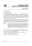
2-1. GRID PATTERN LAYOUT AND MOORING
POINT STRENGTH. The grid pattern layout illustrating
the 17 to 20 foot on center mooring points is depicted
in gure 2-1.
a.
This pattern readily accommodates all the helicopters in the army eet and should be used
as the standard for new mooring installations.
b.
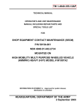
The strength of each mooring point should be
capable of reacting to the design loads depicted in gure 2-2.
(6) Tie-down UH-1 as specied in the appropriate Technical Manual, except that a forward main rotor blade tie-down strap is required.
(7) Tie-down CH/MH-47 as specied in the
appropriate Technical Manual.
b.
2-2. MOORING PAD MARKING. Marking the mooring pad to properly position the aircraft is recommended
if the pad is to be used exclusively for one type of aircraft.
2-3.
GENERAL TOOLS AND EQUIPMENT.
a.
All aircraft will use polyester rope for rotor blade
tie-down. Refer to table 2-1.
(1) Tie-down OH-58D as specied in the appropriate aircraft Technical Manual.
(2) Tie-down OH-58A/C as specied in the
appropriate Technical Manual, except that
two main rotor blade tie-down boots are
required.
(3) Tie-down AH-64 as specied in the appropriate Technical Manual. Ensure that the
ropes are strong enough to allow the main
rotor blades to be secured at the required
locations.
(4) Tie-down UH-60 as specied in the appropriate Technical Manual.
Tie-down and Mooring Equipment. Refer to
table 2-1.
(1) Acquisition and maintenance of all required tie-down and mooring equipment
is the responsibility of the aviation units.
(2) The identied chain and chain adjuster
shall be used as the primary mooring
equipment for all helicopters when parked
at their home installation and Army policy
(per paragraph 1-6) requires mooring.
Exceptions to the use of mooring chains
is only approved under special circumstances where chain has proven to be
undesirable such as the crossover mooring on the CH/MH-47D.
(3) Mooring chains and chain adjusters are
not considered yaway equipment. The
10,000 pound capacity polyester mooring
strap with ratchet buckle, NSN 5340-01233-3063, is the identied yaway which
may be used when aircraft deployed away
from their home station require mooring
and chains are not available. The CGU1B, 5000 pound capacity nylon tie-down
strap, NSN 1670-00-725-1437, is only authorized when hard stand mooring points
are not available and the eld mooring kit
is used.
(5) Deleted.
Change 5
2-1
Change 5
ITEM
DESCRIPTION
P/N
Mooring Hardware and Consumables
NSN
QUANTITY PER AIRCRAFT
AH-64
CH/MH-47
UH-60
UH-1
OH-58
1
CHAIN ADJUSTER
(See gure 2-3)
MB-1
MIL-T-25959
1670-00-212-1149
6
6
6
6
6
2
CHAIN W/HOOK
(See gure 2-3)
FOR MB-1
627728A
1670-00-516-8405
12
16
12
12
12
3
LINK, CHAIN
(See gures 4-3 and 4-4)
9/32 INCH
664228
4010-01-231-3388
6
4
4
4
4
4*
LINK, CHAIN
(See gures 4-3 and 4-4)
3/8 INCH
577-0165
4010-01-193-9331
6
8
6
6
6
5**
CHAIN, ALLOY
(See gure 4-3)
1/4 INCH
RRC271
4010-00-988-3181
(100 FT DRUM)
6 EA
1 FT
4 EA
1 FT
4 EA
1 FT
4 EA
1 FT
4 EA
1 FT
6
SHACKLE
(See gure 4-13)
204-031393-1
4030-00-977-6940
4
3
7
SHACKLE, ANCHOR
(See gure 4-3)
RRC271
4030-00-185-0489
6
4
4
4
4
8
SHACKLE, ANCHOR
(See gure 4-3)
NAS1042-8
4030-00-542-3180
6
4
4
4
4
9
BOLT
(See gure 4-13)
AN5-22A
AN5H22A
5306-00-151-2621
5306-00-180-2672
3
3
TM 1-1500-250-23
2-2
Table 2-1.
Table 2-1.
ITEM
DESCRIPTION
Mooring Hardware and Consumables — Continued
P/N
NSN
QUANTITY PER AIRCRAFT
AH-64
CH/MH-47
UH-60
UH-1
OH-58
10
BOLT, g 4-13
AN5-23A
AN5H23A
5306-00-151-2620
5306-00-180-2673
3
3
11
WASHER, g 4-13
AN960PD516 5310-00-187-2399
6
12
NUT, g 4-13
MS21042L5
5310-00-807-1476
3
13***
BUSHING, g 4-14
14
PIN, QUICK
RELEASE, g 4-15
MS17985520
5315-00-702-3102
15
ROPE, 1/2 INCH
POLYESTER
MIL-R-24537
4020-01-028-3843
(200 FT ROLL)
16
ROPE, 1/2 INCH
POLYESTER
MIL-R-24335
4020-00-765-3928
(1000 FT ROLL)
17
ROPE, 1/2 INCH
POLYESTER
MIL-R-30500
4020-00-630-4873
(1200 FT ROLL)
3
3
2-3
TM 1-1500-250-23
Change 5
Change 5
ITEM
DESCRIPTION
Mooring Hardware and Consumables — Continued
P/N
NSN
QUANTITY PER AIRCRAFT
AH-64
CH/MH-47
UH-60
UH-1
18
ROPE, 3/8 INCH
POLYESTER
700324R
4020-01-318-5428
(600 FT ROLL)
19
PIN, RETAINING
AN416-2
5315-00-223-6112
2
20****
CHAIN, WELDLESS
NAS1455B30 4010-01-331-7273
6P
2
21***** STRAP, WEBBING
22****** TIE DOWN
*
**
***
****
*****
******
B-D10000R/O234HH-24
1730-00-075-1055
6
Optional, replaces items 3 and 5 if unavailable.
Cut 1/4 inch chain to 1 ft sections (14 links).
If item 13 is unavailable, see gure 4-13 to make a replacement.
Cut chain to 6 inch sections.
Contact AMCOM engineering (DSN 897-4905) or comm. 256-313-4905, for approval to use webbing strap
for mooring.
To be used on CH/MH-47 aircraft with main rotor blade P/N 114E5060-1.
OH-58
TM 1-1500-250-23
2-4
Table 2-1.
TM 1-1500-250-23
Figure 2-1. Mooring Pad Hardpoint Spacing
Change 3
2-4.1/(2-4.2 blank)
TM 1-1500-250-23
THE LOADS SHOWN ARE THE MAXIMUMS CALCULATED
TO MOOR ARMY HELlCOPTERS IN 100 KNOT WINDS,
IT IS RECOMMENDED THAT THE MOORING DEVICE BE
CAPABLE OF WITHSTANDING THE MAXIMUM LOADS SHOWN.
Figure 2-2. Mooring Pad Maximum Load Conditions
2-5
TM 1-1500-250-23
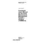
MB-1 CHAIN ADJUSTER ASSEMBLY
EASY LOADING
QUICK RELEASE AT 10,000 LB. LOAD
POSITIVE LOCK
ADJUSTMENT TO ANY CHAIN LINK -
ULTIMATE LOAD — 14,100 LBS.
PLUS 3-1/2” OF SCREW ADJUSTMENT.
MEETS REQ. OF SPECIFICATION -
WEIGHT — 3-1/2 LBS. MAXIMUM
MIL-T-25959 TYPE MB-1
HOOK — THROAT /8"
TO BE USED WITH TYPE 1 CHAIN
STEEL PARTS CADMIUM PLATED
ASSEMBLY PER MIL-C-6458
Figure 2-3. MB-1 Chain Adjuster Assembly
2-6
TM 1-1500-250-23
CHAPTER 3
TIE-DOWN PROCEDURES
3-1. GENERAL TIE-DOWN PROCEDURES. Line
tension tie-down lines from all main rotor blades shall
be taut, but care must be taken to ensure excessive
deection of blades below the static jacking, droop
position, as stated in the specic aircraft -23 TMs, is not
exceeded.
3-2.
brace or to secure to the aft wing store suspension lug. The other rope attaches to the aft
jacking tting at FS450. This conguration will
prevent the boot from slipping off.
d.
UH-60 tie-down blades as specied in the -23
Technical Manual and as shown in gure 3-4 of
this general TM. To prevent damage from the
lock release cable in strong winds, wrap the
cable several times around the tie-down rope
and slip the end loop through one of the cable
wraps.
e.
Deleted.
f.
UH-1 tie-down aft blades as specied in the
-23 Technical Manual and as shown in gure
3-6 of this general TM. Engage hook of main
rotor tie-down in hole of tting on each rotor
blade and position blade above tailboom. Pull
on tie-down to remove spanwise slack from
the rotor system and secure rotor blade by
wrapping the tie-down rope rmly around tailboom as shown in gure 3-6. Tie forward
rope tie-down rope to tow rings, as shown in
gure 3-6, on landing gear skid. Additional
security of main rotor can be accomplished
by inserting an AN416-2 safety retaining pin
through a 0.060 inch hole drilled through the
hook of the main rotor tie-down. The hole is
drilled perpendicular to the plane of the handle,
0.25 inch from the insertion end of the hook.
Secure the safety retaining pin to the hook
handle with a 6-inch piece of NAS1455B30-6P
chain and safety wire. Insert the safety retaining pin through the hook after inserting the
hook through the rotor blade tting. In the nal
tie-down position, the blades must not exceed
6 inches of additional droop from having been
pulled down. This applies to both metal and
composite blades.
g.
CH/MH-47 tie-down blades as specied in -23
Technical Manual and gures 3-7 or 3-8 of
this general TM. Use gure 3-7 for normal aircraft tie-down. As an option, the CH/MH-47
blades may be secured to the mooring pad
hard points, as shown in gure 3-8, provided
the aircraft is secured using the mooring procedures in this TM.
SPECIFIC AIRCRAFT TIE-DOWN.
a.
OH-58D tie-down blades as specied in the
-23 Technical Manual and as shown in gure
3-1 of this general TM. Use the polyester rope
referenced in this manual.
b.
OH-58A/C tie-down blades as specied in the
-23 Technical Manual and as shown in gure
3-2 of this general TM. Securely tie the straps
of the boot to the polyester rope near the boot.
Ensure the ropes are long enough to cross
and tie in the position illustrated. The forward
blade shall be tied down using the same boot
strap/rope arrangement device. The ropes
shall be tied to the forward eyebolts of the
landing skid. The ropes, as an option, can be
secured to the forward eyebolts of the landing
skid by either tying or using a self closing hook
that is the same strength or as strong as the
polyester rope, to anchor tie-down rope to the
skid rings.
NOTE
Optional tie-down procedure for the OH-58A/C
is applicable also to the UH-1 aircraft.
c.
AH-64 tie-down blades as specied in the -23
Technical Manual and as shown in gure 3-3
of this general TM. Ensure that the main rotor blade tie-down boot is in good repair and
that the two nylon end straps are securely attached (refer to gure 3-3, blow-up). Replace
the 3/8 inch nylon rope with polyester rope.
3/8 inch diameter standard polyester rope can
be substituted directly. 1/2 inch diameter standard polyester rope can be secured to the boot
by forming a small loop with the existing nylon rope and tying the polyester rope to the
loop. Ensure that the rope is long enough to
reach the proper aircraft hard points. The right
aft boot must have an additional length of rope
to secure to the aft outboard wing pylons way
Change 5
3-1
TM 1-1500-250-23
Figure 3-1. OH-58D Tie-Down Conguration
Figure 3-2. OH-58A/C Tie-Down Conguration
3-2
TM 1-1500-250-23
Figure 3-3. AH-64 Tie-Down Conguration
Change 5
3-3
TM 1-1500-250-23
Figure 3-3a. Deleted
3-4
Change 4
TM 1-1500-250-23
Figure 3-4. UH-60 Tie-Down Conguration
Figure 3-5. Deleted
Change 5
3-5
TM 1-1500-250-23
Figure 3-6. UH-1 Tie-Down Conguration
Figure 3-7. CH/MH-47 Tie-Down Conguration
3-6
Change 5
TM 1-1500-250-23
Figure 3-8. CH/MH-47 Tie-Down Conguration (Optional)
Change 5
3-7/(3-8 Blank)
TM 1-1500-250-23
CHAPTER 4
MOORING PROCEDURES
4-1.
GENERAL MOORING.
a.
Aircraft Placement. Position the aircraft on the
mooring pad parallel to the centerline of the
pad and located fore and aft per the dimension
in the gure for that aircraft as shown in gures
4-6 through 4-12.
b.
Adjusters. Ensure that adjusters are fully extended.
c.
Securing Aircraft, secure aircraft to the pad using the chains and adjusting device provided
at each of the pad mooring points. The chains
are to be attached to the aircraft as illustrated
in that aircraft gure and are to be adjusted to
remove slack in the chain. During installation
manually make the chains as taut as possible
prior to using adjuster. The adjuster has a limited travel capacity.
d.
Position Variance. The position of the aircraft
with respect to the pad and the pad dimension
may vary up to 12 inches.
The aircraft’s tail rotor is in very close proximity
to the aft tie-down point. The aft fuselage mooring point should not be used or approached any
time the rotor is turning. For initial shipboard
mooring conguration (four chains), attach two
chains to each forward tie-down tting, or the
mooring lug on each main landing gear trailing
arm if the forward fuselage tie-down ttings are
not installed
(1) Position the aircraft on the mooring pad
with the longitudinal centerline of the aircraft directly above and parallel to the longitude line of the pad as shown in gure
4-6. Position the forward mooring rings located on main landing gear struts, 6-feet
aft of the forward mooring points on the
pad as shown in gure 4-6 of this general
TM.
NOTE
It will be necessary to open the fairings which
shield the forward mooring rings, before nal
aircraft positioning. A Frearson screwdriver will
be required.
Ensure chain links are inserted into the MBI
chain adjuster as shown in gure 4-2. Incorrect
insertion may cause the MBI adjuster to fail and
compromise the mooring system.
(2) Connect two chain assemblies from the
aircraft mooring rings to the forward mooring pad points.
(3) Connect two chain assemblies from the
center mooring pad points to the mooring
ring located on the lower surface of the
tailboom at F.S. 450.
NOTE
All deviations from the nominal position degrade the wind resistance of the mooring
scheme. The tolerance suggested will degrade
the scheme by an acceptably small amount.
e.
Mooring Hardware. The hardware to be furnished with the mooring pad is dened in 2-1
and gures 4-1 thru 4-5. Use conguration
1 (g. 4-1) and a l/2-inch anchor shackle or
conguration 2 (g. 4-2) to meet requirements
which do not allow the mooring pad hardware
shown in gure 4-3 to be permanently installed.
A ball peen hammer is required to install the
link, chain detachable. Cut the chain link to the
correct length (See gures 4-4 and 4-5).
4-2. SPECIFIC AIRCRAFT MOORING
PROCEDURES.
a.
AH-64 Helicopter Mooring Procedures.
(4) Connect two chain assemblies from the
rear mooring pad points to the mooring
ring located on the lower surface of the
tailboom at F.S. 450.
(5) Tighten the MB-1 chain adjusters to remove the slack from all mooring chains.
No tools are required.
b.
CH/MH-47 Helicopter Mooring Procedures.
(1) Position the aircraft on the mooring pad
with longitudinal centerline of the aircraft
directly above and parallel to the longitudinal axis of the pad as shown in gure
4-7. Position the aircraft forward landing
gear mooring rings 8-feet-9 inches aft of
Change 5
4-1
TM 1-1500-250-23
the forward mooring points on the pad as
shown in gure 4-7 of this general TM.
(e) Tighten the MB-1 chain adjusters to
remove the slack from all mooring
chains. No tools are required.
(3) For mooring the UH-60 per gure 4-8a:
c.
(2) Connect two crossing chain assemblies
from the forward landing gear mooring
rings diagonally to the forward mooring
pad points.
(a) Position the aircraft cargo hook directly in-line with the center mooring
pad points.
(3) Connect two side chain assemblies from
the forward landing gear mooring rings to
the forward mooring pad points.
(b) Connect two lateral chain assemblies
from the aircraft cargo hook to the
center mooring pad points (Ref. gure 4-8a, view A-A).
(4) Connect two crossing chain assemblies
diagonally from the aft aircraft landing
gear mooring rings to the rear mooring
pad points.
(c) Connect two chain assemblies from
the center mooring pad points to the
aft aircraft mooring rings at F.S.485.
(5) Connect two side chain assemblies from
the aft aircraft landing gear mooring rings
to the rear mooring pad points.
(d) Connect two chain assemblies from
the aft aircraft mooring rings to the
rear mooring pad points.
(6) Tighten the MB-1 adjusters to remove the
slack from all mooring chains. Not tools
are required.
(e) Tighten the MB-1 chain adjusters to
remove the slack from all mooring
chains. No tools are required.
UH-60 Helicopter Morning Procedures.
(1) Position the aircraft on the mooring pad
with the longitudinal centerline of the aircraft directly above and parallel to the longitudinal axis of the pad as shown in gures 4-8, 4-8a, 4-8b, 4-8c and 4-8d. Figures 4-8, 4-8c and 4-8d are to be used for
aircraft that do not have external tanks installed Figure 4-8a is to be used when aircraft have external tanks installed. Figure
4-8b is to be used for the EH-60 aircraft.
(2) For mooring of the UH-60 per gure 4-8:
(a) Position the aircraft front rooming
rings directly in-line with the front
mooring pad points.
(b) Connect two chain assemblies from
the forward aircraft mooring rings at
F.S. 308 to the front rooming pad
points.
(c) Connect two chain assemblies from
the front mooring pad points to the aft
aircraft mooring rings at F.S.485.
(d) Connect two chain assemblies from
the aft aircraft mooring rings to the
center rooming pad points.
4-2
Change 5
(4) For mooring the EH-60 per gure 4-8b:
(a) Position the aircraft front rooming
rings directly in-line with the front
mooring pad points.
(b) Connect two chain assemblies from
the forward aircraft mooring rings at
F.S. 308 to the front mooring pad
points.
(c) Connect two chain assemblies from
the center mooring pad points to the
forward aircraft rooming rings at F.S.
308.
(d) Connect two chain assemblies from
the aft aircraft mooring rings at F.S.
485 to the center mooring pad points.
(e) Tighten the MB-1 chain adjusters to
remove the slack from all mooring
chains. No tools are required.
(5) For alternate mooring of UH-60 per gure
4-8c:
(a) Position the aircraft front mooring
rings directly in-line with the center
mooting pad points as shown in gure
4-8c.
TM 1-1500-250-23
(b) Connect two chain assemblies from
the forward aircraft mooring rings at
F.S. 308 to center mooring pad points
as shown in gure 4-8c.
d.
Deleted.
e.
UH-1 Helicopter Mooring Procedures.
(1) Position the aircraft on the mooring pad
with the longitudinal centerline of the aircraft directly above and parallel to the
longitudinal axis of the pad as shown in
gure 4-10. The forward jack-points, located at F.S. 61.96, should be located
approximately 2 feet aft of the forward
mooring points as dimensioned in gure
4-10. The aft mooring points are located
at F.S. 211.58.
(c) Connect two chain assemblies from
the center mooring pad points to the
aft aircraft mooring rings at F.S.485 as
shown in gure 4-8c.
(d) Connect two chain assemblies from
the aft aircraft mooing rings at F.S.
485 to the rear mooring pad points as
shown in gure 4-8c.
(2) Before mooring the aircraft will be necessary to install a mooring clevis at each of
the four jacking points. A mechanics tool
kit will be required.
(e) Tighten the MB-l chain adjusters to
remove the slack from all mooring
chains. No tools are required.
(6) For alternate mooring UH-60 per gure
4-8d.
(a) Position the aircraft on the mooring
pad with longitudinal centerline of the
aircraft directly above and parallel to
the longitudinal axis of the pad as
shown in gure 4-8d. Position the
aircraft front mooring rings, at F.S.
308.10 feet aft of the forward mooring
pad points as shown in gure 4-8d.
NOTE
Older UH-1 aircraft have jack points with a nominal bolt hole size of .25 inches compared with
.312 inches on newer UH-1 aircraft. On the
older UH-1 aircraft the existing .25 inch hole will
need to be enlarged to .312 inches to accommodate the current bolt and shackle conguration.
(3) Connect two chain assemblies from the
forward jack-points to the forward mooring
pad points.
(b) Connect two chain assemblies from
the front mooring rings at F.S. 308
to the forward mooring pad points as
shown in gure 4-8d.
(4) Connect two chain assemblies from the
forward mooring pad points to the rear
jack-points.
(c) Connect two chain assemblies from
the front mooring rings at F.S. 308
to the center mooring pad points as
shown in gure 4-8d.
(d) Connect two chain assemblies from
the aft aircraft mooring rings at F.S.
308 to the center mooring pad points
as shown in gure 4-8d.
(e) Connect two chain assemblies from
the aircraft mooring rings at F.S. 485
to the rear mooring pad points.
(f)
(5) Connect two chain assemblies from the
rear jack-points to the center mooring pad
points.
NOTE
It is highly recommended that UH-1 helicopters
be own with the mooring hardware installed at
all times to permit a rapid response to weather
emergencies.
f.
OH-58 Helicopter Mooring Procedures.
Tighten the MB-1 chain adjusters to
remove the slack from all mooring
chains. No tools are required.
Change 5
4-3
TM 1-1500-250-23
NOTE
The mooring hardware is to be carried in the
yaway kit. Flying the OH-58 with the mooring
hardware installed may result in damage to the
aircrafts’ honeycomb surface. Retain all hardware together for each specic installation: due
to wear, the bushings may not be interchangeable.
(1) Position the aircraft on the mooring pad
with the longitudinal centerline of the aircraft directly above and parallel to the longitudinal axis of the pad as shown in gures 4-11 and 4-12. The forward jackpoints are to be located 4 feet aft of the forward mooring pad points as dimensioned
in gure 4-11 and 4-12.
(2) Before mooring the aircraft it will be necessary to attach a mooring clevis to each
of the three jackpoints. The clevis provided will not be large enough to accept
the hooks on the mooring chains provided
with mooring pad. Mooring rings are to be
installed on the aircraft as shown in gure
4-13.
4-4
Change 5
For local fabrication of Bushing, P/N NAS725E100, see gure 4-14. Aircraft with oversize
holes may adjust outside diameter to t.
NOTE
Bolt, nut and washer may be eliminated by using a Quick Release Pin as shown in gure 4-15.
(3) Connect two chain assemblies from the
forward jack-points to forward mooring
pad points.
(4) Connect two chain assemblies from the
forward mooring pad points to the rear
jack-point.
(5) Connect two chain assemblies from the
rear jack-point to the center mooring pad
points.
(6) Tighten the MB-1 chain adjusters to remove the slack for all mooring chains.
TM 1-1500-250-23
Figure 4-1. Mooring Hardware Installation Assembly Details - Configuration 1
NOTE
Insure that adequate clearance for the MB1 chain adjuster is provided in relation
to the aircraft and the aircraft hardpoint fitting.
NOTE
Either of the configurations shown can be used to secure the aircraft to the mooring pad.
Figure 4-2. Mooring Hardware Installation Assembly Details - Configuration 2
4-5
TM 1-1500-250-23
REF FIGURE 4-4 AND 4-5.
REF FIGURE 4--4 AND 4--5.
NOTE
All hardware shown can be used to connect the MB1 chain adjuster to the mooring pad hardpoint fitting in figure 4-1.
Figure 4-3. Mooring Hardware Details in Configuration 1 (Figure 4-1)
4-6
TM 1-1500-250-23
STUD ASSEMBLY
LOAD PIN
Figure 4-4. Link, Chain Detachable
4-7
TM 1-1500-250-23
1. Bring the two Hammerlok coupling link body
halves together as shown.
2. Place the stud assembly and the special load
pin made from hardened alloy steel in place
as shown.
Drive the load pin in until the end of the pin is
flush with the surface of the body forging.
Figure 4-5. Link, Chain, Detachable Installation
4-8
TM 1-1500-250-23
Figure 4-6. AH-64 Mooring Conguration
4-9
TM 1-1500-250-23
Figure 4-7. CH/MH47 Mooring Conguration
4-10
Change 5
TM 1-1500-250-23
Figure 4-8. UH-60 Mooring Configuration
4-11
TM 1-1500-250-23
Figure 4-8a. UH-60 Mooring Configuration (When external tanks are installed).
4-12
TM 1-1500-250-23
Figure 4-8b. EH-60 Mooring Configuration.
Change 3
4-12.1
TM 1-1500-250-23
Figure 4-8c. UH60 Mooring Configuration Alternate # 1.
4-12.2
Change 3
TM 1-1500-250-23
Figure 4-8d. UH60 Mooring Configuration Alternate # 2.
Change 3 4-12.3/(4-12.4 blank)
TM 1-1500-250-23
Figure 4-9. Deleted
Change 5
4-13
TM 1-1500-250-23
Figure 4-10. UH-1 Mooring Conguration
4-14
TM 1-1500-250-23
Figure 4-11. OH-58A&C Mooring Conguration
Figure 4-12. OH-58D Mooring Conguration
4-15
TM 1-1500-250-23
Figure 4-13. Mooring Hardware For OH-58A/C&D
4-16
Change 5
TM 1-1500-250-23
Figure 4-14. Bushing Detail for OH-58A/C and D
Figure 4-15. Pin, Quick Release For OH-58A/C and D
Change 5
4-17
TM 1-1500-250-23
4-3.
ground anchors to the aircraft. The following
items are recommended for securing the aircraft:
MOORING ON NON-PAVED SURFACES.
a.
Ground Anchor Kit (NSN 8340-00-951-6423).
Refer to table 4-1 for kit contents and gures
4-16 through 4-22 for component breakout.
NOTE
The Ground Anchor Kit for mooring on
non-paved surfaces is recommended for all
tactical environments (non-paved surfaces).
b.
Function and Description of each kit component.
(1) Ground Anchor. The assembly is composed of a metal arrowhead with approximately three feet of wire rope attached
at the center (gure 4-17). The anchor
is driven into the ground and provides the
mooring base.
(2) Steel Driving Rod. The rod’s outside diameter is 3/4 inch x 3 feet long (gure
4-18). It holds the ground anchor and is
used to drive the anchor into the ground.
Tiedown, Cargo,
Aircraft (Webbing
Binder)
1670-00-725-1437
Tiedown, Cargo,
Aircraft (Webbing
Binder)
5340-01-233-3063
Polyester Rope
(1/2 inch diameter)
4020-01-028-3843
4020-00-765-3928
4020-00-630-4873
d.
NOTE
Refer to the applicable -23 Technical Manual,
under Mooring, to determine the number of anchors required per aircraft. One anchor is required per mooring line.
(1) Refer to gures 4-16 and 4-17 and insert
the ground anchor (arrowhead) stem into
the bottom of the driving rod.
(3) Driving Head. Size is 2 1/4 inches outside
diameter x 2 3/4 inches long. The steel
driving head ts over the top of the driving rod and provides the contact surface
on which to hammer the assembly (gure
4-19).
(2) Refer to gures 4-16 and 4-20 and slip the
holding handle over the driving rod while
driving into the ground.
(4) Holding Tool Handle. (Figure 4-20).
Size is 24 inches long. It is made from
1/4 inch diameter steel rod and slips over
the steel driving rod to hold the unit while
driving the ground anchor arrowhead into
the ground. It allows the assembly to be
held safely while driving.
c.
(3) Refer to gures 4-16, 4-18 and 4-19 and
insert the driving head onto the top of the
driving rod.
(4) Refer to gure 4-16 and drive the anchor head/driving rod assembly into the
ground, hammering on the drive head,
and holding the assembly with the holding
handle.
Connecting the ground anchors to the aircraft.
The kit does not contain rope to connect the
Table 4-1.
ITEM
Installation.
Ground Anchor Kit.
QUANTITY
FIG
NSN
Anchor, Ground
(4 inch arrowhead with
anchoring wire)
50
4-17
4030-00-972-2670
Head, Driving
2
4-19
4030-00-051-8641
Handle, Holding Tool
2
2
4-20
4-18
4030-00-134-4725
4030-00-970-6412
Rod, Steel, Driving
4-18
Change 5
TM 55-1500-250-23
(5) Refer to figure 4-21, View A, and drive the
assembly approximately 3 to 3 1/2 feet until only the
thimble of the wire rope portion of the ground anchor is
above ground.
(6) Refer to figure 4-21, View B, and pull out
the drive rod.
(7) Refer to figure 4-21, View C, and pull up
vertically on the wire rope assembly to seat the anchor.
This will rotate the arrowhead into a horizontal position
and provide a rigid anchor.
(8) Refer to figure 4-22 and attach the
polyester rope or the CGU-1B webbing binder to the
ground anchor and connect it to the aircraft mooring
fitting (remove ail slack).
(9) Ground anchors will be left in the ground
when the aircraft is moved.
e. Larger Ground Anchor for Extreme Sand
Conditions. In extreme sand conditions, a larger
ground anchor may be required. An 8-inch ground
anchor is available for increased holding power. It uses
components similar to the 4-inch ground anchor kit, but
larger in size. The 8-inch ground anchor and its drive
components are as follows:
ITEM
NSN
Ground Anchor
(8 inch aluminum)
4030-00-580-8287
Ground Anchor
(8 inch iron)
4030-01-150-4896
Ground Anchor
(8 inch iron)
4030-00-580-8307
NOTE: All these items are one anchor with wire
rope assembled.
(10) Replacement ground anchors are available.
Rod, Driving
(48 inches long)
4030-00-541-4081
Head, Driving
(2 inches outside diameter x
2 1/4 inches long)
4030-01-008-8053
4-19
TM 1-1500-250-23
Figure 4-16. Ground Anchor Assembly (For Mooring on Nonpaved Surfaces)
4-20
TM 1-1500-250-23
Figure 4-17. Ground Anchor with Wire Rope
Figure 4-18. Driving Rod
Figure 4-19. Drive Head
Figure 4-20. Holding Handle
Change 5
4-21
TM 1-1500-250-23
Figure 4-21. Installation of the Ground Anchor Assembly
4-22
TM 1-1500-250-23
Figure 4-22. Polyester Rope and Webbing Binder
Change 5
4-23/(4-24 Blank)
TM 1-1500-250-23
APPENDIX A
REFERENCES
DA Form 2028 . . . . . . . . . . . . . . . . . . . . . . .
Recommended Change to Publications and Blank Forms
DA PAM 738-751 . . . . . . . . . . . . . . . . . . . . .
The Functional User’s Manual for the Army Maintenance Management
System – Aviation (TAMMS-A)
TM 1-1520-237-23 . . . . . . . . . . . . . . . . . . . .
Aviation Unit and Intermediate Maintenance for Army UH-60A and
EH-60A
TM 1-1520-238-23 . . . . . . . . . . . . . . . . . . . .
Aviation Unit and Intermediate Maintenance for Army AH-64A Helicopter
TM 1-1520-240-23 . . . . . . . . . . . . . . . . . . . .
Aviation Unit and Aviation Intermediate Maintenance Manual Containing
National Repair Standards for CH-47D Helicopter
TM 1-1520-248-23 . . . . . . . . . . . . . . . . . . . .
Aviation Unit And Intermediate Maintenance Manual For Army Model,
OH-58D Helicopter
TM 55-1520-210-23 . . . . . . . . . . . . . . . . . . .
Aviation Unit And Intermediate Maintenance Instructions For Army Model
UH-1H/V/EH-1H/X Helicopters
TM 55-1520-228-23 . . . . . . . . . . . . . . . . . . .
Aviation Unit And Intermediate Maintenance Manual For Army Model
OH-58A And OH-58C Helicopters
Change 5
A-1/(A-2 Blank)
TM 1-1500-250-23
By Order of the Secretary of the Army:
Official:
CARL E. VUONO
General, United States Army
Chief of Staff
THOMAS F. SIKORA
Brigadier General, United States Army
The Adjutant General
DISTRIBUTION:
To be distributed in accordance with DA Form 12-31, AVUM and AVIM Maintenance requirements for AH-64A Helicopter,
Attack (APACHE), UH-60 Helicopter, Utility (BHIP), UH-60A Helicopter, Utility (BLACKHAWK), CH-47A/B/C/D Helicopters, Cargo Transport, All UH-1 series Aircraft, AH-lG/S/F/P/E Helicopters, Attack, and OH-58A/C/D Helicopters, Observation.
These are the instructions for sending an electronic 2028
The following format must be used if submitting an electronic 2028. The subject line must be
exactly the same and all fields must be included; however only the following fields are
mandatory: 1, 3, 4, 5, 6, 7, 8, 9, 10, 13, 15, 16, 17, and 27.
From: “Whomever” [email protected]
To: [email protected]
Subject: DA Form 2028
1
From: Joe Smith
2
Unit: home
3
Address: 4300 Park
4
City: Hometown
5
St: MO
6
Zip: 77777
7
Date Sent: 19--OCT--93
8
Pub no: 55--2840--229--23
9
Pub Title: TM
10
Publication Date: 04--JUL--85
11
Change Number: 7
12
Submitter Rank: MSG
13
Submitter FName: Joe
14
Submitter MName: T
15
Submitter LName: Smith
16
Submitter Phone: 123--123--1234
17
Problem: 1
18
Page: 2
19
Paragraph: 3
20
Line: 4
21
NSN: 5
22
Reference: 6
23
Figure: 7
24
Table: 8
25
Item: 9
26
Total: 123
27
Text:
This is the text for the problem below line 27.
Use Part II (reverse) for Repair Parts and
Special Tool Lists (RPSTL) and Supply
Catalogs/ Supply Manuals (SC/SM)
RECOMMENDED CHANGES TO PUBLICATIONS AND
BLANK FORMS
DATE
8/30/02
For use of this form, see AR 25--30; the proponent agency is ODISC4.
TO: (Forward to proponent of publication or form)(Include ZIP Code)
FROM: (Activity and location)(Include ZIP Code)
Commander, U.S. Army Aviation and Missile Command
MSG, Jane Q. Doe
ATTN: AMSAM--MMC--MA--NP
1234 Any Street
Redstone Arsenal, AL 35898
Nowhere Town, AL 34565
PART 1 - ALL PUBLICATIONS (EXCEPT RPSTL AND SC/SM) AND BLANK FORMS
PUBLICATION/FORM NUMBER
DATE
TM 9-1005-433-24
ITEM
NO.
1
PAGE
NO.
PARAGRAPH
WP0005
PG 3
TITLE Organizational, Direct Support, And
General Support Maintenance Manual for
Machine Gun, .50 Caliber M3P and M3P
Machine Gun Electrical Test Set Used On
Avenger Air Defense Weapon System
16 Sep 2002
LINE
NO. *
FIGURE
NO.
TABLE
NO.
2
RECOMMENDED CHANGES AND REASON
Test or Corrective Action column should identify a different WP number.
E
L
P
M
A
X
E
TYPED NAME, GRADE OR TITLE
* Reference to line numbers within the paragraph or subparagraph.
MSG, Jane Q. Doe, SFC
DA FORM 2028, FEB 74
TELEPHONE EXCHANGE/
AUTOVON, PLUS EXTENSION
SIGNATURE
788-1234
REPLACES DA FORM 2028, 1 DEC 68, WHICH WILL BE USED.
USAPA V3.01
TO: (Forward direct to addressee listed in publication)
FROM: (Activity and location) (Include ZIP Code)
Commander, U.S. Army Aviation and Missile Command
MSG, Jane Q. Doe
ATTN: AMSAM-MMC-MA-NP
1234 Any Street
Redstone Arsenal, AL 35898
Nowhere Town, AL 34565
DATE
8/30/02
PART II - REPAIR PARTS AND SPECIAL TOOL LISTS AND SUPPLY CATALOGS/SUPPLY MANUALS
PUBLICATION NUMBER
PAGE
NO.
COLM
NO.
LINE
NO.
DATE
NATIONAL STOCK
NUMBER
REFERENCE
NO.
TITLE
FIGURE
NO.
TOTAL NO.
OF MAJOR
ITEMS
SUPPORTED
ITEM
NO.
RECOMMENDED ACTION
E
L
P
M
A
PART III - REMARKS (Any general remarks or recommendations, or suggestions for improvement of publications and
blank forms. Additional blank sheets may be used if more space is needed.)
X
E
TYPED NAME, GRADE OR TITLE
MSG, Jane Q. Doe, SFC
TELEPHONE EXCHANGE/AUTOVON,
PLUS EXTENSION
788-1234
SIGNATURE
USAPA V3.01
Use PartII(reverse) for Repair Parts and
Special Tool Lists (RPSTL) and Supply
Catalogs/ Supply Manuals (SC/SM)
RECOMMENDED CHANGES TO PUBLICATIONS AND
BLANK FORMS
DATE
For use of this form, see AR 25--30; the proponent agency is ODISC4.
TO: (Forward to proponent of publication or form)(Include ZIP Code)
Commander, U.S. Army Aviation and Missile Command ATTN:
AMSAM-MMC-MA-NP Redstone Arsenal, AL 35898
FROM: (Activity and location)(Include ZIP Code)
PART 1 --ALL PUBLICATIONS (EXCEPT RPSTL AND SC/SM) AND BLANK FORMS
PUBLICATION/FORM NUMBER
ITEM
NO.
PAGE
NO.
PARAGRAPH
LINE
NO. *
DATE
FIGURE
NO.
TABLE
NO.
TITLE
RECOMMENDED CHANGES AND REASON
* Reference to line numbers within the paragraph or subparagraph.
TYPED NAME, GRADE OR TITLE
DA FORM 2028, FEB 74
TELEPHONE EXCHANGE/
AUTOVON, PLUS
EXTENSION
SIGNATURE
REPLACES DA FORM 2028, 1 DEC 68, WHICH WILL BE USED.
USAPA V3.01
TO: (Forward direct to addressee listed in publication)
Commander, U.S. Army Aviation and Missile Command
ATTN: AMSAM-MMC-MA-NP Redstone Arsenal, AL
35898
FROM: (Activity and location) (Include ZIP Code)
DATE
PART II --REPAIR PARTS AND SPECIAL TOOL LISTS AND SUPPLY CATALOGS/SUPPLY MANUALS
PUBLICATION NUMBER
PAGE
NO.
COLM
NO.
LINE
NO.
DATE
NATIONAL STOCK
NUMBER
REFERENCE
NO.
TITLE
FIGURE
NO.
ITEM
NO.
TOTAL NO.
OF MAJOR
ITEMS
SUPPORTED
RECOMMENDED ACTION
PART III --REMARKS (Any general remarks or recommendations, or suggestions for improvement of publications and blank forms.
Additional blank sheets may be used if more space is needed.)
TYPED NAME, GRADE OR TITLE
TELEPHONE EXCHANGE/AUTOVON,
PLUS EXTENSION
SIGNATURE
USAPA V3.01
PIN:
045826-000
This fine document...
Was brought to you by me:
Liberated Manuals -- free army and government manuals
Why do I do it? I am tired of sleazy CD-ROM sellers, who take publicly
available information, slap “watermarks” and other junk on it, and sell it.
Those masters of search engine manipulation make sure that their sites that
sell free information, come up first in search engines. They did not create it...
They did not even scan it... Why should they get your money? Why are not
letting you give those free manuals to your friends?
I am setting this document FREE. This document was made by the US
Government and is NOT protected by Copyright. Feel free to share,
republish, sell and so on.
I am not asking you for donations, fees or handouts. If you can, please
provide a link to liberatedmanuals.com, so that free manuals come up first in
search engines:
<A HREF=http://www.liberatedmanuals.com/>Free Military and Government Manuals</A>
– Sincerely
Igor Chudov
http://igor.chudov.com/