1
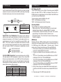
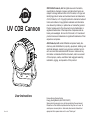
UV COB Cannon
©2013 ADJ Products, LLC all rights reserved. Information,
specifications, diagrams, images, and instructions herein are
subject to change without notice. ADJ Products, LLC logo and
identifying product names and numbers herein are trademarks
of ADJ Products, LLC. Copyright protection claimed includes all
forms and matters of copyrightable materials and information
now allowed by statutory or judicial law or hereinafter granted.
Product names used in this document may be trademarks or
registered trademarks of their respective companies and are
hereby acknowledged. All non-ADJ Products, LLC brands and
product names are trademarks or registered trademarks of their
respective companies.
ADJ Products, LLC and all affiliated companies hereby disclaim any and all liabilities for property, equipment, building, and
electrical damages, injuries to any persons, and direct or indirect economic loss associated with the use or reliance of any
information contained within this document, and/or as a result
of the improper, unsafe, unsufficient and negligent assembly,
installation, rigging, and operation of this product.
User Instructions
Rev. 4/14
Europe Energy Saving Notice
Energy Saving Matters (EuP 2009/125/EC)
Saving electric energy is a key to help protecting the enviroment.
Please turn off all electrical products when they are not in use. To
avoid power consumption in idle mode, disconnect all electrical
equipment from power when not in use. Thank you!
UV COB Cannon UV COB Cannon Introduction
Unpacking: Thank you for purchasing the UV COB Cannon by ADJ
Products, LLC. Every UV COB Cannon has been thoroughly tested
and has been shipped in perfect operating condition. Carefully check
the shipping carton for damage that may have occurred during shipping. If the carton appears to be damaged, carefully inspect your fixture for any damage and be sure all accessories necessary to operate
the unit has arrived intact. In the case damage has been found or parts
are missing, please contact our toll free customer support number for
further instructions. Do not return this unit to your dealer without first
contacting customer support.
Introduction: The ADJ UV COB Cannon is part of a continuing pur-
suit to create high quality intelligent lighting. The UV COB Cannon is a
DMX intelligent, high powered LED par fixture. This fixture can be used
in a stand alone mode or connected in a Master/Slave configuration.
This wash has six operating modes: Sound Active mode, Auto mode,
Fade mode, White Preset Mode (Color Temperature mode) and DMX
control mode.
Customer Support: ADJ Products, LLC provides a customer sup-
port line, to provide set up help and to answer any question should you
encounter problems during your set up or initial operation. You may
also visit us on the web at www.adj.com for any comments or suggestions. Service Hours are Monday through Friday 8:00 a.m. to 4:30 p.m.
Pacific Standard Time.
Voice:
(323) 582-3322
Fax: (323) 582-3108
E-mail: [email protected]
Warning! To prevent or reduce the risk of electrical shock or fire, do
not expose this unit to rain or moisture.
Caution! There are no user serviceable parts inside this unit. Do not
General Instructions
To optimize the performance of this product, please read these
operating instructions carefully to familiarize yourself with the basic
operations of this unit. These instructions contain important safety
information regarding the use and maintenance of this unit. Please
keep this manual with the unit, for future reference.
UV COB Cannon
Features
•
•
•
•
•
•
3 Operating Modes: Sound Active, Manual Mode, & DMX Control
Electronic Dimming 0-100%
Built in Microphone
DMX-512 protocol
3-Pin DMX Connection
3 DMX Modes: 1 Channel Mode, 2 Channel Mode, and 3 Channel Mode
• 5 Selectable Dimmer Curves
• Power Cord Daisy Chain (See page 12)
UV COB Cannon Warranty Registration
The UV COB Cannon carries a 2 year limited warranty. Please fill out
the enclosed warranty card to validate your purchase. All returned
service items whether under warranty or not, must be freight pre-paid
and accompany a return authorization (R.A.) number. The R.A. number
must be clearly written on the outside of the return package. A brief
description of the problem as well as the R.A. number must also be
written down on a piece of paper included in the shipping carton. If
the unit is under warranty, you must provide a copy of your proof of
purchase invoice. You may obtain a R.A. number by contacting our
customer support team on our customer support number. All packages returned to the service department not displaying a R.A. number
on the outside of the package will be returned to the shipper.
attempt any repairs yourself, doing so will void your manufactures warranty. In the unlikely event your unit may require service please contact
ADJ Products, LLC.
PLEASE recycle the shipping carton when ever possible.
ADJ Products, LLC - www.adj.com - UV COB Cannon - User Manual Page 2
ADJ Products, LLC - www.adj.com - UV COB Cannon - User Manual Page 3
UV COB Cannon
Safety Precautions
•To reduce the risk of electrical shock or fire, do not expose this unit rain or moisture
•Do not spill water or other liquids into or on to your unit.
•Do not attempt to operate this unit if the power cord hasbeen
frayed or broken. Do not attempt to remove or break off the ground
prong from the electrical cord. This prong is used to reduce the risk of electrical shock and fire in case of an internal short.
•Disconnect from main power before making any type of connection.
• Do not remove the cover under any conditions. There are no user serviceable parts inside.
•Never operate this unit when it’s cover is removed.
•Never plug this unit in to a dimmer pack
•Always be sure to mount this unit in an area that will allow proper ventilation. Allow about 6” (15cm) between this device and a wall.
•Do not attempt to operate this unit, if it becomes damaged.
•This unit is intended for indoor use only, use of this product out`
doors voids all warranties.
•During long periods of non-use, disconnect the unit’s main power.
•Always mount this unit in safe and stable matter.
•Power-supply cords should be routed so that they are not likely to be walked on or pinched by items placed upon or against them, paying particular attention to the point they exit from the unit.
• Cleaning -The fixture should be cleaned only as recommended by the manufacturer. See page 13 for cleaning details.
•Heat -The appliance should be situated away from heat sources such as radiators, heat registers, stoves, or other appliances (including amplifiers) that produce heat.
•The fixture should be serviced by qualified service personnel when:
A. The power-supply cord or the plug has been damaged.
B. Objects have fallen, or liquid has been spilled into the appliance.
C. The appliance has been exposed to rain or water.
D. The appliance does not appear to operate normally or exhibits a marked change in performance.
ADJ Products, LLC - www.adj.com - UV COB Cannon - User Manual Page 4
UV COB Cannon
Set Up
Power Supply: The ADJ UV COB Cannon contains a automatic voltage switch, which will auto sense the voltage when it is plugged into
the power source. With this switch there is no need to worry about the
correct power voltage, this unit can be plugged in anywhere.
DMX-512: DMX is short for Digital Multiplex. This is a universal pro-
tocol used as a form of communication between intelligent fixtures
and controllers. A DMX controller sends DMX data instructions from
the controller to the fixture. DMX data is sent as serial data that travels from fixture to fixture via the DATA “IN” and DATA “OUT” XLR terminals located on all DMX fixtures (most controllers only have a DATA
“OUT” terminal).
DMX Linking: DMX is a language allowing all makes and models of
different manufactures to be linked together and operate from a single
controller, as long as all fixtures and the controller are DMX compliant. To ensure proper DMX data transmission, when using several
DMX fixtures try to use the shortest cable path possible. The order
in which fixtures are connected in a DMX line does not influence the
DMX addressing. For example; a fixture assigned a DMX address of 1
may be placed anywhere in a DMX line, at the beginning, at the end,
or anywhere in the middle. When a fixture is assigned a DMX address
of 1, the DMX controller knows to send DATA assigned to address 1
to that unit, no matter where it is located in the DMX chain.
Data Cable (DMX Cable) Requirements (For DMX Operation):
The UV COB Cannon can be controlled via DMX-512 protocol. The UV
COB Cannon has 3 DMX channel modes, please see page 7 for the different modes. The DMX address is set on the back panel of the UV COB
Cannon. Your unit and your DMX controller require a standard 3-pin XLR
connector for data input and data output (Figure
1). We recommend Accu-Cable DMX cables.
If you are making your own cables, be sure to
use standard 110-120 Ohm shielded cable (This
cable may be purchased at almost all pro lighting
stores). Your cables should be made with a male
and female XLR connector on either end of the
cable. Also remember that DMX cable must be
Figure 1
daisy chained and cannot be split.
Notice: Be sure to follow figures two and three when making your own
ADJ Products, LLC - www.adj.com - UV COB Cannon - User Manual Page 5
UV COB Cannon
Set Up
POWER
POWER
cables. Do not use DMX512
the ground lug on the XLR connector. Do not connect the cable’sDMX+,DMX-,COMMON
shield conductor to the ground lug or allow the shield
conductor to come in contact with the XLR’s outer casing. Grounding
the shield could cause a short circuit and erratic behavior.
COMMON
1
DMX512 OUT
3-PIN XLR
REMOTE
CONTROL
INPUT
UND
INPUT
2
3
OUTPUT
3
DMX -
1
2
SOUND
XLR Female Socket
XLR Male Socket
1 Ground
DMX +
2 Cold
2 Cold
1 Ground
DMX512 IN
3-PIN XLR
REMOTE
CONTROL
INPUT
INPUT
3
Figure 2
OUTPUT
1
2
XLR Pin Configuration
Pin 1 = Ground
Figure 3
3 Hot
Pin 3 = Data True (positive)
POWER
POWER
Special Note: Line Termination. When longer runs of cable are
3
1
2
used, you may need to use a terminator on the last unit to avoid erratic
behavior. A terminator is a 110-120 ohm 1/4 watt resistor which is connected between pins 2 and 3 of a male XLR connector (DATA + and
DATA -). This unit is inserted in the female XLR connector of the last
unit in your daisy chain to terminate the line. Using a cable terminator
(ADJ part number Z-DMX/T) will decrease the possibilities of erratic
behavior.
Termination reduces signal errors and
DMX512 IN
3-PIN XLR
3
avoids signal transmission problems
and interference. It is always advisable
to connect a DMX terminal, (Resistance
120 Ohm 1/4 W) between PIN 2 (DMX-)
and PIN 3 (DMX +) of the last fixture.
1
2
Figure 4
5-Pin XLR DMX Connectors. Some manufactures use 5-pin DMX-
512 data cables for DATA transmission in place of 3-pin. 5-pin DMX
fixtures may be implemented in a 3-pin DMX line. When inserting standard 5-pin data cables in to a 3-pin line a cable adaptor must be used,
these adaptors are readily available at most electric stores. The chart
below details a proper cable conversion.
3-Pin XLR to 5-Pin XLR Conversion
Conductor
3-Pin XLR Female (Out)
5-Pin XLR Male (In)
Ground/Shield
Pin 1
Pin 1
Data Compliment (- signal)
Pin 2
Pin 2
Data True (+ signal)
Pin 3
Pin 3
Not Used
Do Not Use
Not Used
Do Not Use
ADJ Products, LLC - www.adj.com - UV COB Cannon - User Manual Page 6
POWER
Operating Instructions
LED Display On/Off:
To set the LED display to turn off after 10 seconds, press the MODE
button until either “0010” or “0020” is displayed. Press the UP or
DOWN buttons to toggle between the two modes. Press SAVE once
you have found your desired mode.
To set the display press the MODE button until:
“0010” = LED display on at all times.
“0020” = LED display shuts off after 10 seconds.
Termination reduces signal errors and
avoids signal transmission problems
and interference. It is always advisable
to connect a DMX terminal, (Resistance
120 Ohm 1/4 W) between PIN 2 (DMX-)
and PIN 3 (DMX +) of the last fixture.
Pin 2 = Data Compliment (negative)
3 Hot
UV COB Cannon
Operating Modes:
The UV COB Cannon has three operating modes:
• DMX control mode - This function will allow you to control each
individual fixtures traits with a standard DMX 512 controller.
• UV Dimmer Mode - Adjust the intensity of UV output. You can also apply strobing in this mode and select a dimmer curve.
• Sound-Active mode - The unit will react to sound, chasing through the built in programs.
DMX Mode:
Operating through a DMX controller gives the user the freedom to
create their own programs tailored to their own individual needs. The
UV COB Cannon has 3 DMX modes: 1 Channel mode, 2 Channel
mode, and a 3 Channel mode. See page 10 for each DMX traits.
1. This function will allow you to control each individual fixture’s traits with a standard DMX 512 controller.
2. To select your desired Channel mode press the MODE button until:
• To run the 1 Channel Mode, press the MODE button until “XXX1” is displayed. This is the 1 Channel DMX Mode.
• To run the 2 Channel Mode, press the MODE button until “XXX2” is displayed. This is the 2 Channel DMX Mode.
• To run the 3 Channel Mode, press the MODE button until “XXX3” is displayed. This is the 3 Channel DMX Mode.
3. After you have chosen your desired DMX Channel mode plug in the fixture via the XLR connections to any standard DMX control
ler.
5. Please see page 10 for DMX values and traits.
ADJ Products, LLC - www.adj.com - UV COB Cannon - User Manual Page 7
UV COB Cannon
Operating Instructions
UV Manual Dimmer Mode:
1. Plug the fixture in and press the MODE button until:
2. When “XXX4” is displayed you are in dimming mode. Press the UP and DOWN buttons to adjust intensity.
3. When “XXX5” is displayed you are in strobing mode. Press the UP and DOWN buttons to adjust strobing.
4. When “XXX6” is displayed you are in dimmer curve adjustment. Press the UP and DOWN buttons to scroll through the different curve modes. See the dimmer curve chart on page 11.
Sound Active Mode:
In this mode the UV COB Cannon will react to sound, and chase
through the different colors.
1. Plug the fixture in and press the MODE button until “0017” is dis-
played.
2. The fixture will now change via sound.
3. Press the UP or DOWN button so that “0027” is displayed. This is sound sensitivity adjustment. Use the UP and DOWN buttons to adjust the sensitivity.
ADJ Products, LLC - www.adj.com - UV COB Cannon - User Manual Page 8
UV COB Cannon
Master-Slave Configuration
Master-Slave Configuration:
This function will allows you to link units together to run in a Master-Slave
mode. In Master-Slave operation one unit will act as the controlling unit
and the others will react to the controlling units built-in programs. Any
unit can act as a Master or as a Slave however, only one unit can be programmed to act as the “Master.”
Master-Slave Connections and Settings:
1. Daisy chain your units via the XLR connector on the rear of the unit. Use standard XLR data cables to link your units together. Remember
that the Male XLR connector is the input and the Female XLR con-
nector is the ouput. The first unit in the chain (master) will use the female XLR connector only. The last unit in the chain will use the male XLR connector only.
2. On the “Master” unit, press the MODE button until “0018” is dis-
played. This is the “Master” setting, press the SAVE button. After you have set it to the “Master” setting, set your desired operating mode.
3. For the “Slave” unit, press the UP or DOWN button so that “0028” is displayed. This is the “Slave” setting, press the SAVE button.
4. Now connect the “Slave” unit to the “Master” unit using the XLR con-
nections.
ADJ Products, LLC - www.adj.com - UV COB Cannon - User Manual Page 9
UV COB Cannon
Channel
1
Value
1 - 255
UV COB Cannon
Channel
1
2
Value
1 - 255
1 - 255
UV COB Cannon
Channel
1
2
3
Value
1 - 255
1 - 255
0 - 20
21 - 40
41 - 60
61 - 80
81 - 100
101 - 255
1 Channel Mode
Function
UV COB Cannon
Dimmer Curve Chart
DIMMING
0% - 100%
2 Channel Mode
Function
DIMMING
0% - 100%
STROBING
SLOW - FAST
3 Channel Mode
Function
DIMMING
0% - 100%
STROBING
SLOW - FAST
DIMMER CURVES
STANDARD
STAGE
TV
ARCHITECTURAL
THEATRE
DELAY MODE CONTROL
ADJ Products, LLC - www.adj.com - UV COB Cannon - User Manual Page 10
ADJ Products, LLC - www.adj.com - UV COB Cannon - User Manual Page 11
UV COB Cannon
Installation
The UV COB Cannon is fully operational in three different mounting
positions, hanging upside-down from a ceiling, hanging sideways on
trussing, or set on a flat level surface. The unit should be mounted
using a mounting clamp (not provided), affixing it to the mounting
bracket that is provided with the unit. Always ensure that the unit is
firmly fixed to avoid vibration and slipping while operating. Always
ensure that the structure to which you are attaching the unit is secure
and is able to support a weight of 10 times the unit’s weight. Also,
always use a safety cable that can hold 12 times the weight of the
unit when installing the fixture.
The equipment must be installed by a professional, and it must be
installed in a place where it is out of the reach of people’s grasp.
UV COB Cannon
Power Cord Daisy Chain
With this feature you can connect the fixtures to one another
using the IEC input and output sockets. The quantity that can be
connected is 3 fixtures maximum for 120V, and 5 fixtures maximum for 240V. After the maximum fixtures has been reached you
will need to use a new power outlet. They must be the same fixtures. DO NOT mix fixtures.
UV COB Cannon
Fuse Replacement
Disconnect the unit from its power source. Remove the power cord
from the unit. Once the cord has been removed, you will find that the
fuse holder is located inside the power socket. Insert a flat-head screw
driver into the power socket and gently pry out the fuse holder. Remove
the bad fuse and replace with a new one. The fuse holder also has a
holder for a spare fuse.
UV COB Cannon
Cleaning
Due to fog residue, smoke, and dust cleaning the internal and external optical lenses must be carried out periodically to optimize light
output.
1. Use normal glass cleaner and a soft cloth to wipe down the
outside casing.
2. Clean the external optics with glass cleaner and a soft cloth
every 20 days.
3. Always be sure to dry all parts completely before plugging
the unit back in.
Cleaning frequency depends on the environment in which the fixture
operates (i.e. smoke, fog residue, dust, dew).
UV COB Cannon
Trouble Shooting
Listed below are a few common problems the user may encounter,
with solutions.
Unit not responding to DMX:
1. Check that the DMX cables are connected properly and are wired correctly (pin 3 is “hot”; on some other DMX devices pin 2 may be ‘hot’). Also, check that all cables are connected to the right connectors; it does matter which way the inputs and outputs are connected.
Unit does not respond to sound:
1. Quiet or high pitched sounds will not activate the unit.
2. Make sure that Sound Active mode is activated.
ADJ Products, LLC - www.adj.com - UV COB Cannon - User Manual Page 12
ADJ Products, LLC - www.adj.com - UV COB Cannon - User Manual Page 13
UV COB Cannon
Specifications
UV COB Cannon
Model: UV COB Cannon
Voltage: 100V ~ 240V/50~60Hz
LEDs:
100W COB UV LED
Beam Angle:
33 Degrees
Working Position:
Any safe working position
Power Consumption:
120W
Power Cord Daisy Chain:3 Fixtures Max. (120V)
5 Fixtures Max. (240V)
Fuse:
3.15 Amp or 4 Amp
Weight: 11lbs./ 4.98Kgs.
Dimensions:
12.75” (L) x 11” (W) x 8” (H)
320 x 278 x 200mm
Colors:
UV
DMX Channels:
3 DMX Modes: 1 Channel Mode,
2 Channel Mode, & 3 Channel
Mode
Auto Sensing Voltage: This fixture contains a automatic volt-
age switch, which will auto sense the voltage when it is plugged
into the power source.
Please Note: Specifications and improvements in the design of
this unit and this manual are subject to change without any prior
written notice.
ADJ Products, LLC
6122 S. Eastern Ave. Los Angeles, CA 90040 USA
Tel: 323-582-2650 / Fax: 323-725-6100
Web: www.adj.com / E-mail: [email protected]
ADJ Products, LLC - www.adj.com - UV COB Cannon - User Manual Page 14
A.D.J. Supply Europe B.V.
Junostraat 2
6468 EW Kerkrade
Netherlands
[email protected] / www.adj.eu
Tel: +31 45 546 85 00 / Fax: +31 45 546 85 99