1
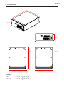
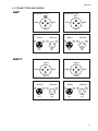
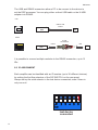
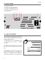
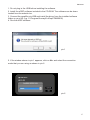
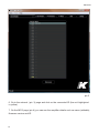
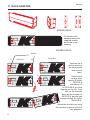
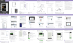
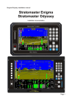
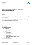
USER MANUAL
KA7
KA7-7
ENGLISH
CONTENTS
SYMBOLS 5
DECLARATION OF CONFORMITY 7
1.INTRODUCTION 9
2. APPLICATIONS 9
3. KEY FEATURES 10
4. UNPACKING 10
5. ACCESSORIES INCLUDED 10
6. PHYSICAL 11
7. POWER SUPPLY AND VOLTAGE REQUIRED
12
8. BACK PANEL 12
8.1 CONNECTORS AND WIRING 13
8.2 ID ASSIGNMENT 14
ID numbers 15
9. FRONT PANEL 16
10. eDSP SOFTWARE 16
11. RACK ADAPTER 22
12. SERVICE 23
13. WARRANTY 23
14. TECHNICAL DETAILS 25
4
ENGLISH
SYMBOLS
K-array declares that this device is in compliance with the applicable
CE standards and regulations. Before putting the device into operation, please observe the respect ive count ry-specific regulations!
WEEE
Please dispose of this product at the end of its operational lifetime
by bringing it to your local collection point or recycling centre for
such equipment.
This symbol, wherever it appears, alerts you to important operating and
maintenance instructions in the accompanying literature. Read the manual!
Warning! Dangerous voltages: RISK of electric schock.
This symbol alerts the user to recommendations about the product’s use
and maintenance.
This device complies with Restriction of Hazardous Substances Directive.
5
ENGLISH
SAFETY INSTRUCTION
WARNING
• To reduce the risk of electric shock, disconnect the amplifier from the AC mains
before installing audio cable. Reconnect the power cord only after making all signal
connections.
• Connect the amplifier to a two-pole, three wire grounding mains receptacle. The
receptacle must be connected to a fuse or circuit breaker. Connection to any other type
of receptacle poses a shock hazard and may violate local electrical codes.
• Do not install the amplifier in wet or humid locations without using weather protection.
• Do not allow water or any foreign object to get inside the amplifier. Do not put objects
containing liquid on, or near, the unit.
• To reduce the risk of overheating the amplifier, avoid exposing it to direct sunlight. Do
not install the unit near heat emitting appliances, such as a room heater or stove.
• No naked flame sources such like lighted candles should be placed on the device.
• The amplifier should be placed so that its location does not interfere with its proper
ventilation. For example, the appliance should not be situated on a bed, carpet, or
similar surface that may create an obstacle for the ventilation openings.
• CAUTION, RISK OF ELECTRIC SHOCK, DO NOT OPEN. This amplifier contains
potentially hazardous voltages. Do not attempt to disassemble the unit. The unit
contains no user serviceable parts. Repairs should be performed only by factory trained
service personnel.
• Be sure that both voltage set by the selector on the device and AC Power have the
same value.
6
ENGLISH
DECLARATION OF CONFORMITY
This device complies with the essential protection requirements of
Council Directive 89/336/EEC for the implementation of the Laws
of the Member States relating to electromagnetic compatibility. This
declaration applies to all specimens and manufacturing drawings
which form part of this declaration. Assessment of compliance
of the product with the requirements relating to electromagnetic
compatibility was based on the following standards.
Please observe the respective country-specific regulations!
EN 55013:1990+A12+A13+A14
EN 55020:1994+A11+A12+A13+A14
EN 61000-3-2:1995+A1+A2+A14
EN 61000-3-3:1995
EN 60065:1998
IEC 60065:1998
WEEE
Please dispose of this product at the end of its operational lifetime by
bringing it to your local collection point or recycling centre for such
equipment.
The contents of this manual are furnished for informational purpose only. Hp Sound
Equipment s.r.l. assumes no responsability for any errors or inaccuracies thatmay appear in this manual. Hp Sound Equipment s.r.l. reserves the right to make modifications
without prior notice.
7
ENGLISH
8
ENGLISH
KA7 /KA7-7
High technology Class D power amplifier
1.INTRODUCTION
The KA professional rack amplifier
line has been designed to meet all
the needs of touring and installation
applications in which need a large
amount of power together with the
maximum flexibility, small sizes
and weight. The sophisticated
electronics on-board allow the
system to reach outstanding output
power levels with high efficiency.
The on-board DSP provide perfect
signal processing for all K-array
products, providing safe working
conditions and a wide choice of
dedicated presets to solve most
needs of high-end applications.
2. APPLICATIONS
•
•
•
•
•
Theatrical sound reinforcement
Concert halls, clubs, houses of worship
Exhibit audio for museum displays
Cinema and installed AV systems
Stage monitoring
9
3. KEY FEATURES
•
•
•
•
•
•
•
•
•
•
ENGLISH
Very light weight
Compact design, 2 units half rack
Optical limiters
Electronically protected
Over-high efficiency
DSP on-board to drive all K-array products
Remote control via USB or RS485
Management software
Top quality components for outstanding performance
Aluminum frame
4. UNPACKING
Each K-array device is built to the highest standard and thoroughly inspected before
leaving the factory. Carefully inspect the shipping carton, then examine and test your new
loudspeaker. If you find any damage immediately notify the shipping company. Only the
consignee may institute a claim procedure regarding the system’s electronic equipment.
5. ACCESSORIES INCLUDED
•
1 x CD-ROM
•
1 x CAT 5, 50 cm cable
•
1 x 50cm xlr cable
•
1 x power link cable
•
1 x Rack adapter kit
•
1 x User’s manual
10
ENGLISH
6. PHYSICAL
27 cm
20 cm
8.8 cm
8.8 cm
20 cm
27 cm
20 cm
Weight:
KA7 KA7-7 27 cm
20 cm
4.03 Kg (8.89 lbs)
4.44 Kg (9.79 lbs)
11
ENGLISH
7. POWER SUPPLY AND VOLTAGE REQUIRED
KA7 and KA7-7 operate safely and without audio discontinuity if the AC voltage stays
within an operating window of 90 V to 260 V.
Check the voltage before connecting the amplifier to the AC power.
A higher voltage could seriously damage the device.
8. BACK PANEL
1. Powercon IN
2. Powercon OUT (max 15A)
3. Speakon1 OUT (CH1, CH2)
4. Speakon1 OUT (CH3, CH4)
5. DIP Switch ID assigment
6. USB remote control connector
7. RS485 remote control connectors
8. Input 1 level PAD
3
2
4
5 6
7 8
10 12
13
11
15
1
1
9. Input 2 level PAD
10. Input 1 ground lift switch
11. Input 2 ground lift switch
12., 13. Input 1 XLR balanced parallel
connectors
14., 15. Input 2 XLR balanced parallel
connectors
12
9
14
ENGLISH
8.1 CONNECTORS AND WIRING
KA7
SPEAKON 1 OUT
SPEAKON 2 OUT
N.C.
2+
CH2 - 2-
2+
1- CH1 -
N.C. 2-
1- CH2 -
1+
CH1 +
1+
CH2 +
XLR connector
CH1 out
CH1 in
CH1
ho t
2
1
CH1 CH1
grd ho t
1
CH1
grd
CH2 in
CH2
ho t
2
2
3
3
1
CH4 +
2+
1- CH1 -
1- CH3 -
CH4 - 21+
CH3 +
XLR connector
2
1
3
CH1
cold
CH1 CH1
grd ho t
2
SPEAKON 2 OUT
1+
CH1 +
CH1
ho t
CH2
grd
3
CH2
cold
CH2 +
2+
CH1 in
1
CH2
cold
SPEAKON 1 OUT
CH2 - 2-
CH2 out
CH2 CH2
grd ho t
3
CH1
cold
CH1
cold
KA7-7
XLR connector
XLR connector
CH1 out
1
3
CH1
cold
CH1
grd
2
CH2 in
CH2
ho t
2
1
3
CH2
cold
CH2 CH2
grd ho t
CH2 out
1
CH2
grd
2
3
CH2
cold
13
ENGLISH
The USB and RS485 connectors allow a PC to be connect to the device to
set the DSP processor. You can plug either a direct USB cable or the K-USB
adapter into RS485.
USB
DIRECT USB
CABLE
AMPLIFIER’S
DSP
PC
RS485
K-USB
ACCESSORY
AMPLIFIER’S
DSP
RS485
USB
PC
It is possible to connect multiple modules to the RS485 connection, up to 31
IDs.
8.2 ID ASSIGNMENT
Each amplifier can be identified with an ID number (up to 30 different choices)
by setting the first five selectors of the DIP SWITCH on the rear panel.
Always set up the sixth selector in the last device connected, even if there is
only one unit.
last device
connected
14
ID numbers
ENGLISH
This configuration of the dip
switches (ID = 31) is reserved.
eDsp will not recognize the
connected device.
Do not use this configuration.
15
ENGLISH
9. FRONT PANEL
1. Protection indicator
2. Indicator of proper operating
3. Indicator of signal/clip CH1 IN
4. Indicator of signal/clip CH2 IN
5. Power switch
1
2
3 4
5 6
5
KA7
10. eDSP SOFTWARE
The amplifier is equipped with two INPUTS
and four DSP OUTPUTS that work using
K-array eDSP software.
This software runs on all Windows PCs,
it communicates via USB or RS485
(K-USB).
The eDSP software allows you to manage
EQ, Dynamics and signal levels in real
time.
The amplifier out of the box has no on
board preset loaded. It’s necessary to
connect it via USB the first it is used, and
upload the right preset for your application.
16
SYSTEM REQUIRED
Operating systems:
Win XP/ Vista / 7.
Minimum requirements:
CPU
300 MHz
RAM
128 Mb
Recommended requirements:
RAM
512 Mb
ENGLISH
1. Do not plug in the USB before installing the software.
2. Install the eDSP software included in the CD-ROM. The software can be downloaded from the website too.
3. Connect the amplifier via USB and install the driver from the installed software
folder on your HD (e.g. C:\Program\K-array\K-eDsp\CDM20602)
4. Run the eDSP software
pic.1
5. If the window shown in pic.1 appears, click on No and select the connection
mode that you are using as shown in pic.2.
pic.2
17
ENGLISH
pic.3
6. Go to the network (pic. 3) page and click on the connected ID (the unit highlighted
in yellow)
7. On the INFO page (pic.4) you can see the amplifier details such as name (editable),
firmware version and ID.
18
ENGLISH
1
2
3
pic.4
1. Click here to get the stored parameters from the device memory to the software.
2. Click here to send the current software parameters to the DSP module.
3. Click here to upgrade the firmware when new versions come out.
8. Click on the USER button (shortcut: F4), from here you can change EQ, levels and
dynamics.
19
5
6
ENGLISH
7
1
2
3
4
pic.5
1. Four different cells of EQ. can be enabled in three different modes: Low
Shelf, High Shelf or Peak. The Low and High Shelf filters boost (or reduce)
energy at the set frequencies and all frequencies above it(in low shelf) or below
it (in high shelf) . The Peak filter boosts (or reduces) energy at the set frequency
and across a band of frequencies close to the set frequency.
2. The ‘Q’ value sets the width of the band of frequencies that will be boosted
(or reduced)
3. The ‘Freq’ value sets the frequency around which you are operating.
4. The ‘Gain’ value sets how much energy has to be boosted (or reduced)
around the set frequency.
5. Main CH1 INPUT level
6. Dedicated stereo dynamic processor.
7. Press the ‘Link’ button to group together CH1 and CH2 settings.
20
ENGLISH
Once the settings are finished you have to store them to the eeprom by clicking on
Store to eeprom (F11) in the ‘Preset’ menu.
To save the preset you have made click save on the ‘Preset’ menu.
To load a previously stored preset click load on the ‘Preset’ menu.
To send a preset to all the connected modules click load to all in the ‘Preset’ menu.
To send and store the same preset to all the connected modules click load and store
to all in the ‘Preset’ menu.
To load and store at once a preset on the actual eDSP click on load and store to
node in
the ‘Preset’ menu.
If you want to send one preset to different groups of IDs click send preset to ID in the
preset menu.
21
ENGLISH
11. RACK ADAPTER
SINGLE RACK
Fix the two rack
adapters using the
supplied screws
as shown in the
drawing.
DOUBLE RACK
spacers
S1
DEVICE A
DEVICE B
S2
Unscrew the 4
anchor points of
the front panels
and remove
them.
S1
S2
Remove the
smaller steel
spacer (S2)from
DEVICE A
and adjust S1
on DEVICE B as in the
diagram on the left. Then
refit the front panels
fixing all four screws on
DEVICE B and the two
screws through S1 on the
DEVICE A .
Attach the two devices using
the last two screws and fix the
rack adapters.
22
12. SERVICE
ENGLISH
To obtain service:
1) Contact the official K-array distributor in your country. They will direct you to the
service centre.
2) If you are calling for service, have the serial number(s) of the unit(s) at hand for
reference. Ask for Customer Service, and be prepared to describe the problem clearly
and completely.
3) If the problem cannot be resolved over the phone, you must return the unit for
service.
4) You will be given an RA (Return Authorization) number for job tracking. Refer to
this number on shipping materials and in all correspondence concerning the repair.
Shipping charges are the responsibility of the purchaser.
Any attempt to modify or replace components of the device will invalidate your
warranty. Service must be performed by an authorized K-array service center.
Cleaning:
• Clean the product enclosures using a soft, dry cloth only.
• Do not use any solvents, chemicals, or cleaning solutions containing alcohol,
ammonia, or abrasives.
• Do not use any sprays near the product or allow liquids to spill into any openings.
13. WARRANTY
K-array KA7-7
are warranted against manufacturing defects in materials or
craftsmanship over a period of 2 years from the date of original purchase. During the
warranty period K-array will, at its discretion, either repair or replace products which
prove to be defective, provided that the product is returned in its original packaging,
shipping prepaid, to an authorized K-array service agent or distributor. K-array cannot
be held responsible for defects caused by unauthorized modifications, improper use,
negligence, exposure to inclement weather conditions, acts of God or accidents, or any
use of this product that is not in accordance with the instructions provided by K-array.
K-array is not liable for consequential damages.
This warranty is exclusive and no other warranty is expressed or implied.
This warranty does not affect your statutory rights.
23
ENGLISH
24
14. TECHNICAL DETAILS
ENGLISH
KA7
KA7-7
Output power
Max power 4Ω
2 x 350 w(EIAJ)
4 x 350 w(EIAJ)
Max power 8Ω
2 x 190 w
4 x 190 w (EIAJ)
Max power - bridged 4Ω
(EIAJ)
1000 w(EIAJ)
Max power - bridged 8Ω
700 w(EIAJ)
Connectors
2 x 4-pin Speakon
2 x 4-pin Speakon
Speakon 1 wiring
pin 1+,1- = CH1 pin 2+, 2- = CH2
pin 1+,1- = CH1 pin 2+, 2- = CH3
Speakon 2 wiring
pin 1+,1- = CH2 pin 2+, 2- = N.C.
pin 1+,1- = CH2 pin 2+, 2- = CH4
Audio specs
Slew rate 8Ω
S/N Ratio
Distorsion (THD, DIM, SMPTE)
Input impedance
Gain
Output
Bandwidth
Damping factor 8Ω (100 Hz)
30V/mS
30V/mS
>113 dB/A
>113 dB/A
<0.005%
<0.005%
20K bal. 10K unbal.
20K bal. 10K unbal.
32 dB
32 dB
Unbalanced to ground
Unbalanced to ground
3 Hz - 45 KHz
3 Hz - 45 KHz
>1000
>1000
Protection
Thermal protection
Yes
Yes
Short circuit / over-load
Yes
Yes
Clip limit,
Analog signal limit
Yes
Yes
Audio Input
Connectors
2 x Male + 2 x Female 3-pin bal .XLR
2 x Male + 2 x Female 3-pin bal .XLR
Wiring Pin1 = Ground / Pin2 = hot (+) / Pin3 = cold (-) Pin1 = Ground / Pin2 = hot (+) / Pin3 = cold (-)
Remote control Input
Connectors
RJ45 / USB
RJ45 / USB
Remote control
Protocol
RS485 / USB
RS485 / USB
Power Input
Connectors
2 x PowerCon IN/OUT
2 x PowerCon IN/OUT
AC power
Operating range
90 - 260 Vac 50-60Hz with PFC (auto range)
90 - 260 Vac 50-60Hz with PFC (auto range)
P. nom
140 VA
140 VA
Max input voltage
265 Vac
265 Vac
Power factory
(1/2 max out/ 8Ω)
0.97
0.97
70 Vac
Minimum operation voltage
70 Vac
Physical
Dimensions
20 (1/2 U rack) x 8.8 (2U rack) x 27 cm
(7.87”x 3.46”x 10.63”)
20 (1/2 U rack) x 8.8 (2U rack) x 27 cm
(7.87”x 3.46”x 10.63”)
4.03 Kg (8.89 lbs)
4.44 Kg (9.79 lbs)
Weight
Notes for data
New materials and design are introduced into existing products without previous notice. Present systems may differ in some
respects from those presented in this brochure
25
ENGLISH
NOTES
26
ENGLISH
APPROVAL
K-array declares that this device is in compliance with the applicable CE standards and regulations.
Before putting the device into operation, please observe the
respective country-specific regulations!
WEEE
Please dispose of this product at the end of its operational lifetime by bringing it to your local collection point or recycling
centre for such equipment.
The contents of this manual are furnished for informational purpose only. Hp Sound Equipment s.r.l. assumes no responsability for any errors or inaccuracies that may appear in this manual.
Hp Sound Equipment s.r.l. reserves the right to make modifications without prior notice.
27
UMCA77AA01ENb
k-array is a brand of
HP Sound Equipment s.r.l.
Viale Roma 7/i - 50037
San Piero a Sieve (Firenze) - Italy
tel. +39 055 8487222 - fax. +39 0558487238
e-mail: [email protected]
www.k-array.com