1
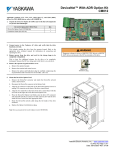
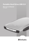
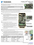
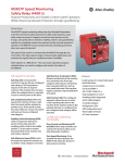
F7 Drive Safe-Off Option
Technical Manual
Drive Models: CIMR-F7UXXXXXX-118
Document Number: TM.F7.03, Date: 10/15/07, Rev: 07-10
Contents:
1.0 Overview ........................................................................ 2
2.0 Basic Concept ................................................................ 3
3.0 Changes From Standard Product .................................. 4
4.0 Limitations ...................................................................... 5
5.0 Related Parameters and Functions ................................ 5
6.0 Function Description ...................................................... 5
7.0 Implementation ............................................................... 6
8.0 Connections ................................................................... 8
9.0 Precautions .................................................................... 9
10.0 References ................................................................. 10
11.0 Yaskawa Support ....................................................... 11
This document provides instructions for the proper installation and use of the Yaskawa drive with “Safe-Off” option. This
document is a supplement to the F7 technical manuals, and describes the effects on the drive functions and parameters when
the “Safe-Off” option is installed. Read and understand this document as well as the standard drive technical manuals before
attempting to install, adjust, operate, inspect or maintain the drive. Observe all cautions and warnings in this document and
the standard drive technical manuals. The Safe-Off option adds functionality to a standard AC drive to enhance or enable its
use in specific applications. The Safe-Off option requires a special control board (ETC 619320 - S7160) and terminal board
(ETC 619330) which replace the standard drive control board and terminal board.
The Safe-Off control board and terminal board are installed in the drive before delivery. The drive nameplate will display the
conventional model number followed by “-118” indicating that the Safe-Off option is installed.
When seeking support for a drive with the Safe-Off option, it is imperative to provide the unique part number shown on the drive
nameplate including the “-118” indicating Safe-Off.
WARNING
The Safe-Off function does not cut the power supply to the drive
nor does it provide electrical isolation to the motor. The drive
must be disconnected from the power mains before any
installation or maintenance work is done. Always use “lock-out,
tag-out” or similar approved safety protocol when servicing
equipment.
CAUTION
Remove the jumper (link) connecting Safe-Off terminals BB,
BB1 and SN to use the Safe-Off option. Follow the wiring
diagrams illustrated in this document for implementing Safe-Off.
If Safe-Off is not to be used, leave the jumper in place.
Date: 10/15/07, Rev: 07-10
Page 1 of 12
Remove this
jumper to use
Safe-Off function
TM.F7.03
1.0
Overview
First, there is nothing inherently unsafe about an F7 without the Safe-Off option. However, the F7’s operation is
fully programmable. It is commanded by programmable inputs. Multiple sources (keypad, terminals, serial
communications, option cards, etc.) can issue a Run command. When turning off the motor is essential to safetyrelated functions in the system, the F7’s flexibility necessitates a reliable mechanism to ensure that the motor will
stop and cannot be started regardless of how the drive is programmed, configured or controlled otherwise.
The Safe-Off option, when used with other safety components, provides protection according to EN954-1
Category 3 for safe stop and protection against restart. An F7 drive equipped with the Safe-Off option is just one
component in a safety control system. To assure that the Safe-Off function appropriately fulfills the safety
requirements of the application, a thorough risk assessment shall be done according to ISO12100 for the whole
safety system at the final installation. All components in the system must be appropriately selected and applied to
achieve the desired safeguarding.
The Safe-Off function performs a safe stop according to the EN60204-1 Stop Category 0 referred to as
“uncontrolled stop by power removal” or “coast to stop.” Safe-Off is certified to meet the requirements of the
EN954-1, Safety Category 3. The Safe-Off function is implemented totally in hardware on the F7 control board.
Safe-Off disables the motor, not the drive controller. Power to the control board and display is maintained so all
parameters, monitors and fault data may be read and observed. Also, all communications (Modbus, Profibus,
DeviceNet, EtherNet/IP, etc.) stay active.
The Safe-Off function uses two independent hardware channels to redundantly block the driver signals to the
output devices (IGBTs) so the motor is disabled and operation prevented. Redundancy ensures that a single fault
in any of the parts involved in Safe-Off does not lead to a loss of the safety function.
Safe-Off is all electronic. No mechanical moving parts (relays) are involved in the Safe-Off circuitry. Safe-Off is
suitable in applications classified as “medium risk” where coasting to a stop is the appropriate response to a fault
condition.
Safe-Off merely prevents the motor from moving. The Safe-Off option does not serve as a motor disconnecting
means (NEC Article 430 Part IX) and does not provide electrical safety. It is only suitable for preventing motor
operation when people are working near parts of a machine affected by the drive system.
The Safe-Off option should not be used as the normal means to start and stop the drive.
Date: 10/15/07, Rev: 07-10
Page 2 of 12
TM.F7.03
2.0
Basic Concept
The Safe-Off function option involves two added digital inputs, BB and BB1, as well as supply terminal SN on the
terminal board. Removing the voltage from either terminal BB or BB1 disables the drive motor output. Both
terminals BB and BB1 must be energized (connected to SN) for the drive to start or run the motor. BB and BB1
individually break the drive signals to the output devices (IGBTs) resulting in a reliable means of removing power
from a motor and preventing it from restarting until both BB and BB1 are reenergized. As long as either BB or BB1
is open (deenergized), no command given the drive will start or run the motor no matter how the drive is
programmed, configured or commanded.
The F7 with Safe-Off option is shipped from the factory with a jumper connecting BB and BB1 to SN. This jumper
allows the F7 “out of the box” to operate as a conventional F7 drive without Safe-Off. The jumper must be
removed to use the Safe-Off option.
Safe-Off terminals
shown with factory
jumper in place
The time from opening either Safe-Off input until the drive output is switched off is less than 10 milliseconds.
Date: 10/15/07, Rev: 07-10
Page 3 of 12
TM.F7.03
3.0
Changes From Standard Product
The Safe-Off option requires a special F7 control board (ETC 619320-S7160) and terminal board (ETC 619330)
which replace the standard drive control board and terminal board. The most salient difference is the ETC 619330
terminal board’s third row of control terminals containing the BB, BB1 and SN Safe-Off connections. The SN
Safe-Off terminal is electrically connected to the standard SN terminal.
BB and BB1 have the same opto-coupler interface as the other digital inputs, S1 through S8, and operate from the
same isolated 24V on-board control supply. Whereas S1 through S8 connect only to the F7’s I/O processor, BB
and BB1 also connect to hardware buffers that can block the gate drive signals to the IGBTs and prevent the motor
from running.
The drive software interprets BB and BB1 exactly as a conventional “External Baseblock” command. Otherwise, all
standard F7 parameters and monitors retain their original functionality. In fact, multifunction digital inputs (S3
though S8) can still be programmed as conventional “External Baseblock N.O.” and “External Baseblock N.C.” to
maintain compatibility with previous utilizations.
Gate Drive
Signals from
Processor
to IGBT
Gate Drivers
Enable
To Processor
SC
Safe-Off Circuitry Blocks the IGBT Gate Signals Through Two Separate Hardware Channels
Date: 10/15/07, Rev: 07-10
Page 4 of 12
TM.F7.03
4.0
Limitations
An F7 with the Safe-Off option has all the functionality of the conventional F7.
5.0
Related Parameters and Functions
The Safe-Off option does not add or modify any parameters, monitors, multifunction input codes, multifunction
output codes, faults or alarms.
6.0
Function Description
The blocking function of Safe-Off terminals BB and BB1 is fully implemented in hardware. Nevertheless, the drive
software still monitors BB and BB1 inputs and treats them as a conventional External Baseblock command like
Multifunction Inputs programmed with codes “8” or “9.” When the drive receives a Baseblock command (either
software or hardware implemented), it turns off the output devices (IGBTs) and no output voltage is applied to the
motor. The motor coasts. The drive can be forced into a baseblock state by either closing a digital input configured
for “Ext Baseblk N.O.” (H1-0x= 8) or opening a digital input configured for “Ext Baseblk N.C.”
(H1-0x= 9) or by opening either Safe-Off input BB or BB1.
The time from opening either Safe-Off input until the drive output is switched off is less than 10 milliseconds.
When the Baseblock command is removed, the drive immediately performs the Speed Search function to catch
the coasting (or stopped) motor and ramp it back to the commanded speed. Parameter b3-01 determines which
method of speed search (either Current Detection or Speed Estimation) is used. See the F7 Drive Programming
Manual TM.F7.02 for complete descriptions of Baseblock and Speed Search functions.
Date: 10/15/07, Rev: 07-10
Page 5 of 12
TM.F7.03
7.0
E(G)
Implementation
BB BB1 SN
SN SC SP A1 A2 +V AC -V A3 MP AC RP R+ RS1 S2 S3 S4 S5 S6 S7 S8 FM AC AM IG S+ S-
M5 M6 MA MB MC
M3 M4 M1
M2
E(G)
Physical Arrangement of Control Terminals for F7 with Safe-Off Option (including Factory-Installed
Jumpers)
For a complete description of the terminals other than BB, BB1 and SN, see the F7 User Manual TM.F7.01. When
shipped from Yaskawa, the drives have removable jumpers connecting SC and SP and connecting BB, BB1 and
SN. This jumper arrangement is compatible with physical contacts or NPN-type output drivers. In this configuration
the inputs are “current-sourcing” and can be driven by outputs that are “current-sinking.”
Date: 10/15/07, Rev: 07-10
Page 6 of 12
TM.F7.03
N.C.
Run Fwd
Fault Relay
Run Rev
N.O.
H1-01 = 24 (Ext Flt)
H1-02 = 14 (Clr Flt)
(Running) 0 = H2-01
N.O.
(at Zero Spd) 01 = H2-02
N.O.
(at Set Spd) 02 = H2-03
N.O.
H1-03 = 03 (Ref Sel 1)
H1-04 = 04 (Ref Sel 2)
H1-05 = 06 (Jog Ref Sel)
H1-06 = 08 (Ext Baseblk)
Safe-Off
Terminals
BB = Hardware Baseblk
BB1 = Hardware Baseblk
3.3KΩ
F7 Safe-Off
Control Board
+ 24VDC
- (Isolated)
+15VDC @ 20mA max
Auto Ref
(Output Freq) 02 = H4-01
H3-05 = 02 (Manual Ref)
(Output Current) 03 = H4-04
H3-09 = 0 (Freq Cmd A1 Bias)
S1-2
250Ω
2KΩ
H6-01 = 0 (Freq Ref)
+15VDC
(Output Freq) 02 = H6-06
47Ω
3KΩ
-15VDC @ 20mA max
AC = 0V
Analog Common
+ Chassis (Heatsink) Ground
Iso
RS485
/422
+ S1-1
110Ω
F7 Safe-Off Control Board
Date: 10/15/07, Rev: 07-10
Page 7 of 12
TM.F7.03
8.0
Connections
If the Safe-Off function is used, the factory-installed wire link (jumper) between terminals SN, BB and BB1 must be
removed entirely. Connect the drive to an EN954-1, Safety Category 3 interrupting device so that a Safe-Off
request breaks the connection between the terminal SN and both terminals BB and BB1. The normal connection is
shown below. Wires W1 and W2 should be run separately from W3 and W4. A short circuit from W1 or W2 to W3 and
W4 would bridge the contacts of the safety device and nullify its operation.
To maintain the integrity of the safety system, no other control input should be connected to Safe-Off terminals BB
or BB1.
Run Fwd
Run Rev
H1-01 = 24 (Ext Flt)
H1-02 = 14 (Clr Flt)
W4
H1-03 = 03 (Ref Sel 1)
H1-04 = 04 (Ref Sel 2)
W3
H1-05 = 06 (Jog Ref Sel)
EN954-1
Category 3
Safety
Device
H1-06 = 08 (Ext Baseblk)
BB = Hardware Baseblk
BB1 = Hardware Baseblk
W2
3.3KΩ
W1
+ 24VDC
- (Isolated)
Normal Connection to EN954-1 Category 3 Safety Device
Safe Disable Terminals
No.
BB
Terminals
BB, BB1,
SC, SN
Date: 10/15/07, Rev: 07-10
Signal Name
Hardware Baseblock
Signal Level
BB1
Hardware Baseblock1
24VDC, 8mA
photocoupler
SN
Sequence input neutral
-
SC
Sequence input common
-
Terminal
Screws
Phoenix
type
Tightening
Torque
(N•m)
0.5 to 0.6
Possible Wire
Sizes
Recommended
Wire Size
mm2 (AWG)
mm2 (AWG)
Solid wire:
0.14 to 2.5
Stranded wire:
0.14 to 1.5
(26 to 14)
0.75
(18)
Page 8 of 12
Wire Length
50 m or less
TM.F7.03
9.0
Precautions
If two separate signal lines from the safety device to inputs BB and BB1 are used as shown on the previous page,
the drive does not need to be installed in an IP54 enclosure. If only one signal line from the safety device to the
drive is used, and BB and BB1 are linked at the drive, then the drive must be installed in an enclosure with a
protection degree of at least IP54 in order to maintain EN954-1, Safety Category 3 compliance.
If the safety device and the drive are installed in separate cabinets, the Safe-Off wires must be installed in a
short-circuit proof manner.
Run Fwd
Run Rev
H1-01 = 24 (Ext Flt)
H1-02 = 14 (Clr Flt)
H1-03 = 03 (Ref Sel 1)
H1-04 = 04 (Ref Sel 2)
H1-05 = 06 (Jog Ref Sel)
EN954-1
Category 3
Safety
Device
H1-06 = 08 (Ext Baseblk)
BB = Hardware Baseblk
BB1 = Hardware Baseblk
3.3KΩ
+ 24VDC
- (Isolated)
Only Permissible in IP54 Enclosure
The Safe-Off function does not cut the power supply to the drive and does not provide electrical isolation to the
motor. The drive must be disconnected from the power mains before any installation or maintenance work is done.
Always use “lock-out, tag-out” or similar approved safety protocol when servicing equipment.
Risk Assessment Required
To assure that the Safe-Off function appropriately fulfills the safety requirements of the application, a thorough risk
assessment shall be done according to ISO12100 for the whole safety system at the final installation.
Safety Function Inspection
Check the safety function during periodic maintenance by hitting the STOP switch or tripping the appropriate safety
interlock. Verify both that the applicable motor stops and that the digital operator shows the “BB” indication on the
display. If the motor does not stop or the “BB” indication does not appear, discontinue using the drive at once.
Replace the F7 or its control board and do not resume operation until it is verified both that the applicable motor
stops and that the digital operator shows the “BB” indication on the display.
Date: 10/15/07, Rev: 07-10
Page 9 of 12
TM.F7.03
10.0
References
F7 User Manual TM.F7.01
F7 Drive Programming Manual TM.F7.02
Date: 10/15/07, Rev: 07-10
Page 10 of 12
TM.F7.03
11.0
Yaskawa Support
Drives Technical Support in USA and Canada
Technical Support for Inverters and Drives is available by phone as follows:
Normal:
Monday through Friday during the hours of 8 a.m. to 5:00 p.m. C.S.T.
Emergency:
After normal hours, 7 days a week including weekends and holidays
To contact Drives Technical Support, please call 1-800-YASKAWA (927-5292).
From the menu, dial 2 for Inverter and Drive Products, then 5 for Technical Support.
Drives Technical Support can also be reached by e-mail at [email protected].
Support information, such as technical manuals, FAQs, instruction sheets and software downloads are available at
our website, www.yaskawa.com.
When calling for technical support, please have the following materials available:
• The appropriate Technical Manual in hand because the support associate may refer to this
• Complete nameplate information from the drive and the motor.
• (Confirm that Drive Nameplate Output amps is equal to or greater than Motor Nameplate amps)
• A list with your parameter settings
• A sketch of the electrical power train, from AC line to motor, including filters and disconnects
Field Service, Start Up Assistance, Factory Repair, Replacement Parts, and Other Support
Contact Drives Technical Support for help with any of these needs.
Technical Training
Training is conducted at Yaskawa training centers, at customer sites, and via the internet.
For information, visit www.yaskawa.com or call 1-800-YASKAWA (927-5292).
From the phone menu, dial 2 for Inverter and Drive Products, then 4 for Product Training.
Support in Other Countries
Yaskawa is a multi-national company with offices and service representation around the world.
To obtain support, always contact the local distributor first for guidance and assistance.
Contact the closest Yaskawa office listed for further assistance.
Date: 10/15/07, Rev: 07-10
Page 11 of 12
TM.F7.03
This page intentionally left blank
Date: 10/15/07, Rev: 07-10
Page 12 of 12
TM.F7.03
F7 Drive Safe-Off Option
YASKAWA ELECTRIC AMERICA, INC.
Drives Division
16555 W. Ryerson Rd., New Berlin, WI 53151, U.S.A.
Phone: (800) YASKAWA (800-927-5292) Fax: (262) 782-3418
Internet: http://www.drives.com
YASKAWA ELECTRIC AMERICA, INC.
Chicago-Corporate Headquarters
2121 Norman Drive South, Waukegan, IL 60085, U.S.A.
Phone: (800) YASKAWA (800-927-5292) Fax: (847) 887-7310
Internet: http://www.yaskawa.com
YASKAWA ELECTRIC CORPORATION
New Pier Takeshiba South Tower, 1-16-1, Kaigan, Minatoku, Tokyo, 105-0022, Japan
Phone: 81-3-5402-4511 Fax: 81-3-5402-4580
Internet: http://www.yaskawa.co.jp
YASKAWA ELECTRIC EUROPE GmbH
Am Kronberger Hang 2, 65824 Schwalbach, Germany
Phone: 49-6196-569-300 Fax: 49-6196-888-301
YEA Document Number: TM.F7.03 10/15/2007 Rev. 07-10
Data subject to change without notice. Yaskawa Electric America, Inc.