1
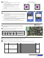
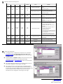
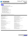
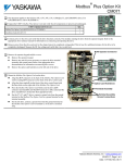
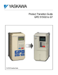
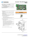
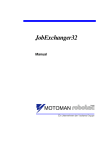
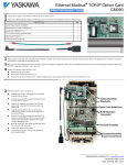
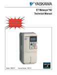
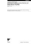
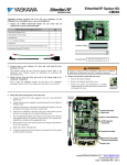
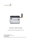
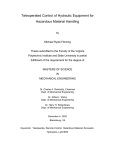
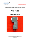
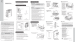
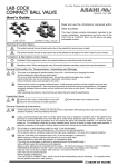
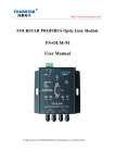
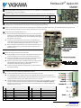
® Profibus-DP Option Kit CM061 This document applies to the Yaskawa F7U, G7U, P7U, E7U, G5M(Spec F), and G5M(600V) drives. For G5U(HHP) drives, refer to IG.G5HHP.12. Unpack the CM061 Profibus-DP Option Kit and verify that all components are present and undamaged. CM061 Option Kit Parts List Qty. Profibus-DP Option Card (SI-P1) 1 Installation Guide (IG.AFD.12) 1 Connect power to the drive and verify that the drive functions correctly. This includes running the drive from the operator keypad. Refer to the appropriate drive technical manual for information on connecting and operating the drive. Remove power from the drive and wait for the charge lamp to be completely extinguished. Wait at least five additional minutes for the drive to be completely discharged. Measure the DC bus voltage and verify that it is at a safe level. Remove the operator keypad and drive cover. Remove the operator keypad and loosen any screws on the front of the terminal cover. Simultaneously pushing the locking tabs on the bottom right and left sides of the terminal cover inward, pull the bottom edge of the terminal cover outward. Loosen any screws on the front of the control cover. Simultaneously pushing the locking tabs on the bottom right and left sides of the control cover inward, pull the bottom edge of the control cover outward. Remove the option card hold-down on the left side of the drive case by carefully compressing the top and bottom until it becomes free of its holder. Lift it out. Mount the Profibus-DP Option Card on the drive. Align the 2CN connector on the back of the Profibus-DP Option Card with its mating J1 connector on the front of the drive control card. Align the two standoffs on the front of the drive control board with the two holes on the right side of the Profibus-DP Option Card. Press the Profibus-DP Option Card firmly onto the drive 2CN connector and standoffs until the J1 connector is fully seated and the drive standoffs have locked into their appropriate holes. Connect the Profibus-DP Option Card ground to a ground terminal on the terminal assembly. Connect the drive to the Profibus-DP communication network. Connect the Profibus-DP network cable as shown in the figure to the right. The cable shield must be contiguous between the beginning and end of any network segment. It is recommended that the shield of the in cable and the out cable be twisted together. Do not connect the shield to the shield connector, rather fold it back and secure it to the cable. Use the pluggable connector that came with the Profibus-DP Option Card. The pluggable connector contains a circuit board that remaps the terminal connections. Do not use an alternate connector. Damage to the Profibus-DP Option Card and/or associated network devices could be damaged if an alternate connector is used. Plug Pin Description Socket Definition Pin Description Definition 1 A In (Green) Negative 1 Reserved No Connection 2 B In (Red) Positive 2 Reserved No Connection 3 A Out (Green) Negative 3 A In/Out (Green) Negative 4 B Out (Red) Positive 4 B In/Out (Red) Positive 5 Shield Shield 5 Shield Shield 6 Reserved No Connection 6 Reserved No Connection Yaskawa Electric America, Inc – www.yaskawa.com IG.AFD.12, Page 1 of 4 Date: 11/17/06, Rev: 06-11 901 901 7 8 7 8 23 23 4 56 Address = S2 (x10) + S1 Example: Set node address to 15 Set address switch 2 to "1 Set address switch 1 to "5" Set the node address. Set the node address for the drive by setting the 10‘s digit with S2 and the 1’s digit with S1. All devices on the network must have unique node addresses. Check the network layout to verify that the node address selected is unique and is within 3 – 99. Node addresses 0 and 1 are typically reserved for master controllers. Node address 2 is typically reserved for diagnostic equipment. 4 56 S2 S1 Set network termination. If this drive is either the first or the last device on the network, including any PLC and/or Profibus-DP Master, and active termination is not used, set the termination resistor switch to ON. If this device is not the first or last device on the network or active termination is used, set the termination resistor switch to OFF. Active termination is the recommended termination method and is required for networks operating above 1.5Mbps. Active termination will eliminate the possibility of network failure due to the removal of a terminated device. The Siemens Profibus Terminator part number is 6ES7 972-0DA00-0AA0. OFF Configure the Profibus-DP network for the drive. Refer to the documentation included with the Profibus configuration utility supplied with the Profibus-DP Master controller. Apply power to the drive and verify that the diagnostic LEDs on the front of the Profibus-DP Option Card are in their correct state. LED Display PWR Solid Green COM Solid Green ERR OFF Content ON Cause WD Flashing Green Normal Normal communication Remove power from the drive and wait for the charge lamp to be completely extinguished. Wait at least five additional minutes for the drive to be completely discharged. Measure the DC bus voltage and verify that it is at a safe level. Reinstall the operator keypad and all drive covers. Apply power to the drive. Set parameters b1-01 and b1-02 to their appropriate values. Refer to the table below for available b1-01 and b1-02 values. Parameter Function Data 0 b1-01 b1-02 Frequency Reference Source Selection Run Command Source Selection Description Default Digital Operator 1 Terminal Strip 2 Built-in Modbus RTU 1 3 Option Card (Profibus-DP Option Card) 4 Pulse Input (F7 and G7 only) 0 Digital Operator 1 Terminal Strip 2 Built-in Modbus RTU 3 Option Card (Profibus-DP Option Card) 1 Yaskawa Electric America, Inc – www.yaskawa.com IG.AFD.12, Page 2 of 4 Date: 11/17/06, Rev: 06-11 LED Status Indicators and Diagnostics LED Display PWR COM ERR Content Cause Option is not powered OFF OFF OFF OFF Power OFF Poor connection to drive Solution WD • Check the main circuit wiring on the drive. • Cycle drive power. • Turn of the drive power. • Check the Profibus-DP Option connection to the drive 2CN connector, • Cycle drive power. Solid Green OFF Solid Red Solid Red CPU Error Option unit CPU error • Cycle drive power. • Replace Profibus-DP Option if fault persists. Solid Green OFF Solid Red Flashing Red Drive Error Error in Drive unit • Cycle drive power. • Replace Profibus-DP Option if fault persists. • Replace drive if fault persists. Solid Green OFF Flashing Red Solid Green Com Error Communication Failure • Check whether the address set in the Profibus-DP Master differs from the address of the option unit. • Check that the master is functioning properly. • Check that the termination resistor is correctly connected to the communication line. • Check whether the communication line is correctly connected (disconnected or poor connection). • Check that the communication line is separated from the main power line. Solid Green Solid Green Flashing Red Solid Green Com Error Communication Fault • Check whether the address is duplicated with any other devices on the ProfibusDP network. Solid Green Solid Green OFF Solid Green CPU Init Initialization Solid Green Solid Green OFF Flashing Green Normal Normal • Wait until WD LED is flashing Profibus-DP Configuration To simplify the drive configuration, the GSD file can be obtained at www.yaskawa.com. Select Downloads, By Inverter Drives, By Product, and Network Comms-Profibus. Then select the file named YASK00CA.GSD. Load the GSD file, YASK00CA.GSD, into the proper directory for the configuration tool used. Retrieve the GSD file form either www.yaskawa.com or www.profibus.org to make sure that the latest GSD file is loaded. Select the Profibus-DP INTER device when adding Yaskawa drives to the Profibus configuration. See the figure to the right. The Profibus-DP Option Card supports three configuration options: Extended Data 1 (32 words of input and output), Extended Data 2 (12 words of input and output) and Basic Data (3 words of I/O). Refer to the Profibus-DP Option Technical Manual (TM.AFD.12) for further information on each configuration. See the figure to the right. Yaskawa Electric America, Inc – www.yaskawa.com IG.AFD.12, Page 3 of 4 Date: 11/17/06, Rev: 06-11 ® Profibus-DP Option Kit CM061 Copies of this Installation Guide along with all technical manuals in “.pdf” format and support files may be obtained from either the CD supplied with the drive or from www.drives.com . Printed copies of any Yaskawa manual may be obtained by contacting the nearest Yaskawa office. Information on Profibus-DP may be obtained from www.profibus.org. Reference documents: Profibus-DP Option Kit Installation Guide – IG.AFD.12 Profibus-DP Option Kit Installation Guide for G5HHP – IG.G5HHP.12 Profibus-DP Technical Manual – TM.AFD.12 G5M Technical Manual – TM.4515 G5M Modbus Technical Manual – TM.4025 F7U Drive User Manual – TM.F7.01 F7U Drive Programming Manual – TM.F7.02 F7U Drive Parameter Access Technical Manual – TM.F7.11 G7U Drive Technical Manual – TM.G7.01 G7U Drive Parameter Access Technical Manual – TM.G7.11 P7U Drive User Manual – TM.P7.01 P7U Drive Programming Manual – TM.P7.02 P7U Drive Parameter Access Technical Manual – TM.P7.11 Modbus® is a registered trademark of Schneider Automation, Inc. Profibus® and Profibus-DP® are registered trademarks of Profibus Nutzerorganisation e.V. YASKAWA ELECTRIC AMERICA, INC. Drives Division 16555 West Ryerson Road, New Berlin, WI 53151, U.S.A. Phone: (800) YASKAWA (800-927-5292) Fax: (262) 782-3418 Internet: http://www.yaskawa.com YASKAWA ELECTRIC AMERICA, INC. Chicago-Corporate Headquarters 2121 Norman Drive South, Waukegan, IL 60085, U.S.A. Phone: (800) YASKAWA (800-927-5292) Fax: (847) 887-7310 Internet: http://www.yaskawa.com MOTOMAN INC. 805 Liberty Lane, West Carrollton, OH 45449, U.S.A. Phone: (937) 847-6200 Fax: (937) 847-6277 Internet: http://www.motoman.com YASKAWA ELECTRIC CORPORATION New Pier Takeshiba South Tower, 1-16-1, Kaigan, Minatoku, Tokyo, 105-0022, Japan Phone: 81-3-5402-4511 Fax: 81-3-5402-4580 Internet: http://www.yaskawa.co.jp YASKAWA ELETRICO DO BRASIL COMERCIO LTDA. Avenida Fagundes Filho, 620 Bairro Saude Sao Paolo-SP, Brasil CEP: 04304-000 Phone: 55-11-5071-2552 Fax: 55-11-5581-8795 Internet: http://www.yaskawa.com.br YASKAWA ELECTRIC EUROPE GmbH Am Kronberger Hang 2, 65824 Schwalbach, Germany Phone: 49-6196-569-300 Fax: 49-6196-888-301 MOTOMAN ROBOTICS AB Box 504 S38525, Torsas, Sweden Phone: 46-486-48800 Fax: 46-486-41410 MOTOMAN ROBOTEC GmbH Kammerfeldstrabe 1, 85391 Allershausen, Germany Phone: 49-8166-900 Fax: 49-8166-9039 YASKAWA ELECTRIC UK LTD. 1 Hunt Hill Orchardton Woods Cumbernauld, G68 9LF, Scotland, United Kingdom Phone: 44-12-3673-5000 Fax: 44-12-3645-8182 YASKAWA ELECTRIC KOREA CORPORATION Paik Nam Bldg. 901 188-3, 1-Ga Euljiro, Joong-Gu, Seoul, Korea Phone: 82-2-776-7844 Fax: 82-2-753-2639 YASKAWA ELECTRIC (SINGAPORE) PTE. LTD. Head Office: 151 Lorong Chuan, #04-01, New Tech Park Singapore 556741, Singapore Phone: 65-282-3003 Fax: 65-289-3003 TAIPEI OFFICE (AND YATEC ENGINEERING CORPORATION) 10F 146 Sung Chiang Road, Taipei, Taiwan Phone: 886-2-2563-0010 Fax: 886-2-2567-4677 YASKAWA JASON (HK) COMPANY LIMITED Rm. 2909-10, Hong Kong Plaza, 186-191 Connaught Road West, Hong Kong Phone: 852-2803-2385 Fax: 852-2547-5773 BEIJING OFFICE Room No. 301 Office Building of Beijing International Club, 21 Jianguomanwai Avenue, Beijing 100020, China Phone: 86-10-6532-1850 Fax: 86-10-6532-1851 SHANGHAI OFFICE 27 Hui He Road Shanghai 200437 China Phone: 86-21-6553-6600 Fax: 86-21-6531-4242 SHANGHAI YASKAWA-TONJI M & E CO., LTD. 27 Hui He Road Shanghai 200437 China Phone: 86-21-6533-2828 Fax: 86-21-6553-6677 BEIJING YASKAWA BEIKE AUTOMATION ENGINEERING CO., LTD. 30 Xue Yuan Road, Haidian, Beijing 100083 China Phone: 86-10-6232-9943 Fax: 86-10-6234-5002 SHOUGANG MOTOMAN ROBOT CO., LTD. 7, Yongchang-North Street, Beijing Economic & Technological Development Area, Beijing 100076 China Phone: 86-10-6788-0551 Fax: 86-10-6788-2878 YEA, TAICHUNG OFFICE IN TAIWAIN B1, 6F, No.51, Section 2, Kung-Yi Road, Taichung City, Taiwan, R.O.C. Phone: 886-4-2320-2227 Fax:886-4-2320-2239 Data subject to change without notice. Yaskawa Electric America, Inc – www.yaskawa.com IG.AFD.12, Page 4 of 4 Date: 11/17/06, Rev: 06-11