1
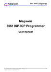
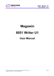
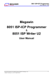
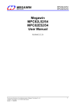
Megawin 8051 Writer
MEGAWIN
User Manual, v3.80
MAKE YOU WIN
Megawin 8051 Writer
User Manual
By Vincent Y. C. Yu
This document information is the intellectual property of Megawin Technology Co., Ltd.
© Megawin Technology Co., Ltd. 2007 All right reserved.
1
Megawin 8051 Writer
MEGAWIN
User Manual, v3.80
MAKE YOU WIN
Contents
1 Introduction ..................................................................................................... 3
2 Install the PC-site AP and Driver for the Writer ............................................... 4
2.1 Install the Driver ........................................................................................................................ 4
2.2 Install the AP ............................................................................................................................. 4
3 MCU’s Flash Memory Configuration ............................................................... 5
3.1
3.2
3.3
3.4
3.5
3.6
3.7
MPC89L516/556X2 ................................................................................................................... 5
MPC89L(E)51/52/53 ................................................................................................................. 6
MPC89L(E)54/58/515 ............................................................................................................... 7
MPC82L(E)52 ........................................................................................................................... 8
MPC82L(E)54 ........................................................................................................................... 9
MPC82G516 ........................................................................................................................... 10
MG84FL54BD & MG84FL54RBD ........................................................................................... 11
4 MCU’s Hardware Option ............................................................................... 12
4.1
4.2
4.3
4.4
4.5
For MPC89L516/556X2 .......................................................................................................... 12
For MPC89L(E)51/52/53/54/58/515 ........................................................................................ 13
For MPC82L(E)52/54 .............................................................................................................. 14
For MPC82G516 ..................................................................................................................... 15
For MG84FL54BD & MG84FL54RBD ..................................................................................... 16
5 Easily Use the Writer..................................................................................... 17
5.1
5.2
5.3
5.4
5.5
The “Auto” button .................................................................................................................... 18
To program the AP-memory & IAP-memory ........................................................................... 19
To program the ISP-memory................................................................................................... 20
To program the AP-memory & IAP-memory & ISP-memory ................................................... 21
To program the hardware option ............................................................................................. 22
5.5.1 Only the hardware option is programmed......................................................................................22
5.5.2 The hardware option is programmed along with the Flash memory..............................................23
5.6
5.7
5.8
5.9
To dump the Target’s Flash data ............................................................................................ 24
To get the checksum of the Target’s Flash data ..................................................................... 25
To disable the hardware option: SB & LOCK .......................................................................... 26
To insert the ISP-code ............................................................................................................ 27
6 Megawin Project File (MPJ File) ................................................................... 30
Revision History ................................................................................................. 32
This document information is the intellectual property of Megawin Technology Co., Ltd.
© Megawin Technology Co., Ltd. 2007 All right reserved.
2
MEGAWIN
MAKE YOU WIN
Megawin 8051 Writer
User Manual, v3.80
1 Introduction
The “Megawin 8051 Writer” is a proprietary programmer designed for all Megawin’s 8051 MCU products. It
functions as a bus-powered USB device and thus doesn’t need any extra power supply. And, the compact
hardware and the friendly software help users easily use this Writer. In addition, its low cost prevents users from
suffering an expensive universal Programmer.
Picture of the “Megawin 8051 Writer”
This document information is the intellectual property of Megawin Technology Co., Ltd.
© Megawin Technology Co., Ltd. 2007 All right reserved.
3
MEGAWIN
Megawin 8051 Writer
MAKE YOU WIN
User Manual, v3.80
2 Install the PC-site AP and Driver for the Writer
2.1 Install the Driver
Plug the Writer into the PC’s USB port, and do as follows when the monitor shows a prompt about new hardware
found.
1)
2)
3)
4)
5)
6)
Select No, not this time, click Next.
Select Install from a list or specific location, click Next.
Select Search for the best driver in these locations and Include this location in the search, click Browse.
Locate the driver folder [(2) PC-site Driver], click OK.
Click Next. The driver installation starts.
Click Finish when the installation completes.
To check if the Programmer was correctly installed, follow the listed steps:
1)
2)
3)
4)
5)
Open the My Computer folder.
Open the Control Panel folder.
Open the System.
Click on the Hardware tab at the top of the dialog box, then click on the Device Manager.
Click on the plus sign in front of the Universal Serial Bus Controllers to check the device listing.
If the installation was completed successfully, you may find an entry, Megawin 8051 Writer, in the listing.
2.2 Install the AP
Run “Setup.exe” (in the [(1) PC-site AP] folder) to install the application program for the Writer on your PC.
Using its default installing setting, you will find the item “Megawin Utilities \ Megawin 8051 Writer (v…)”
appearing in the Windows’ START-menu.
(Note: the v?.?? means the current version and may be upgraded in the future.)
This document information is the intellectual property of Megawin Technology Co., Ltd.
© Megawin Technology Co., Ltd. 2007 All right reserved.
4
Megawin 8051 Writer
MEGAWIN
User Manual, v3.80
MAKE YOU WIN
3 MCU’s Flash Memory Configuration
Before using the “Megawin 8051 Writer”, it is necessary for the user to know the configuration of the MCU’s Flash
memory.
3.1 MPC89L516/556X2
Figure 3.1 shows the configuration of the Flash memory of MPC89L516/556X2. The total memory size is 64K
bytes, and the ISP-memory is user-configured by using this Writer.
For MPC89L516/556X2, there is no dedicated IAP-memory. The AP-memory and IAP-memory are mixed
together and share the same Flash area excluding the ISP-memory.
Figure 3.1: MPC89L516/556X2 Flash Memory Configuration
0000h
Application code
&
nonvolatile data
Mixed
AP-memory
& IAP-memory
64KB - ISP size
Total Flash Memory
64KB
ISP_start_address
(Or none if no ISP)
ISP code
ISP-memory
0KB~8KB (step 0.5KB)
FFFFh
!!! Note: For MPC89L516/556X2, the AP-memory and IAP-memory are mixed together in the same Flash area.
This document information is the intellectual property of Megawin Technology Co., Ltd.
© Megawin Technology Co., Ltd. 2007 All right reserved.
5
Megawin 8051 Writer
MEGAWIN
User Manual, v3.80
MAKE YOU WIN
3.2 MPC89L(E)51/52/53
Figure 3.2 shows the configuration of the Flash memory of MPC89L(E)51/52/53. The total memory size is 15K
bytes, and the ISP-memory is user-configured by using this Writer.
For MPC89L(E)51/52, there is an IAP-memory if the ISP-memory has been configured at least 1K bytes.
For MPC89L(E)53, there is always no IAP-memory.
Table 3.2 shows the relation between IAP-memory and ISP-memory.
Figure 3.2: MPC89L(E)51/52/53 Flash Memory Configuration
0x0000
0x0000
Application
code
0x0000
AP-memory
4KB
Application
code
0x0FFF
AP-memory
8KB
Application
code
Total Flash
Memory, 15KB
0x1FFF
Nonvolatile
data
APmemory
IAP-memory
ISP-memory
start address
Nonvolatile
data
ISP-memory
start address
0x2C00 (ISP=4KB)
0x3400 (ISP=2KB)
0x3800 (ISP=1KB)
IAP-memory
0x2C00 (ISP=4KB)
0x3400 (ISP=2KB)
0x3800 (ISP=1KB)
ISP code
0x2C00 (ISP=4KB)
0x3400 (ISP=2KB)
0x3800 (ISP=1KB)
ISP code
ISP-memory
4KB/2KB/1KB/None
0x3BFF
ISP-memory
start address
ISP code
ISP-memory
4KB/2KB/1KB/None
0x3BFF
MPC89L51
MPC89E51
ISP-memory
4KB/2KB/1KB/None
0x3BFF
MPC89L52
MPC89E52
MPC89L53
MPC89E53
!!! Note: MPC89L(E)53 has no IAP-memory.
Table 3.2: IAP-memory Range and Size for MPC89L(E)51/52
Part No.
IAP-memory Range (Size)
ISP_size =0KB
MPC89L(E)51
(NA)
MPC89L(E)52
(NA)
ISP_size =1KB
ISP_size =2KB
ISP_size=4KB
0x1000~0x37FF
0x1000~0x33FF
0x1000~0x2BFF
(10KB)
(9KB)
(7KB)
0x2000~0x37FF
0x2000~0x33FF
0x2000~0x2BFF
(6KB)
(5KB)
(3KB)
This document information is the intellectual property of Megawin Technology Co., Ltd.
© Megawin Technology Co., Ltd. 2007 All right reserved.
6
Megawin 8051 Writer
MEGAWIN
User Manual, v3.80
MAKE YOU WIN
3.3 MPC89L(E)54/58/515
Figure 3.3 shows the configuration of the Flash memory of MPC89L(E)54/58/515. The total memory size is 63K
bytes, and the ISP-memory is user-configured by using this Writer.
For MPC89L(E)54/58, there is an IAP-memory if the ISP-memory has been configured at least 1K bytes.
For MPC89L(E)515, there is always no IAP-memory.
Table 3.3 shows the relation between IAP-memory and ISP-memory.
Figure 3.3: MPC89L(E)54/58/515 Flash Memory Configuration
0x0000
0x0000
Application
code
0x0000
AP-memory
16KB
Application
code
0x3FFF
AP-memory
32KB
Application
code
Nonvolatile
data
APmemory
Total Flash
Memory, 63KB
0x7FFF
IAP-memory
ISP-memory
start address
ISP-memory
start address
0xEC00 (ISP=4KB)
0xF400 (ISP=2KB)
0xF800 (ISP=1KB)
Nonvolatile
data
IAP-memory
0xEC00 (ISP=4KB)
0xF400 (ISP=2KB)
0xF800 (ISP=1KB)
ISP code
0xEC00 (ISP=4KB)
0xF400 (ISP=2KB)
0xF800 (ISP=1KB)
ISP-memory
4KB/2KB/1KB/None
0xFBFF
ISP-memory
start address
ISP code
ISP code
ISP-memory
4KB/2KB/1KB/None
0xFBFF
MPC89L54
MPC89E54
ISP-memory
4KB/2KB/1KB/None
0xFBFF
MPC89L58
MPC89E58
MPC89L515
MPC89E515
!!! Note: MPC89L(E)515 has no IAP-memory.
Table 3.3: IAP-memory Range and Size for MPC89L(E)54/58
Part No.
IAP-memory Range (Size)
ISP_size =0KB
MPC89L(E)54
(NA)
MPC89L(E)58
(NA)
ISP_size =1KB
ISP_size =2KB
ISP_size=4KB
0x4000~0xF7FF
0x4000~0xF3FF
0x4000~0xEBFF
(46KB)
(45KB)
(43KB)
0x8000~0xF7FF
0x8000~0xF3FF
0x8000~0xEBFF
(30KB)
(29KB)
(27KB)
This document information is the intellectual property of Megawin Technology Co., Ltd.
© Megawin Technology Co., Ltd. 2007 All right reserved.
7
Megawin 8051 Writer
MEGAWIN
User Manual, v3.80
MAKE YOU WIN
3.4 MPC82L(E)52
Figure 3.4 shows the configuration of the Flash memory of MPC82L(E)52. The total memory size is 8K bytes,
and the IAP-memory & ISP-memory are user-configured by using this Writer.
Figure 3.4: MPC82L(E)52 Flash Memory Configuration
0000h
Application
code
AP-memory
IAP_lower_boundary
Total Flash Memory
(Determined by the IAPLB)
8KB
Non-volatile
data
IAP-memory
ISP_start_address
0x1400 for ISP=3KB
0x1800 for ISP=2KB
0x1C00 for ISP=1KB
ISP code
ISP-memory
3KB/2KB/1KB/None
1FFFh
The IAP-memory lower boundary is determined by the MCU’s hardware option IAPLB. Two examples show how
to configure the IAPLB:
Example-1:
4K bytes of IAP-memory is wanted while no ISP-memory is configured.
Î IAPLB should be programmed to 0x10, so the IAP-memory range will be 0x1000~0x1FFF (total 4K bytes).
Example-2:
4K bytes of IAP-memory is wanted while 1K bytes of ISP-memory has been configured at 0x1C00~0x1FFF.
Î IAPLB should be programmed to 0x0C, so the IAP-memory range will be 0x0C00~0x1BFF (total 4K bytes).
The user can find that the range of IAP-memory range is:
Lower boundary = IAPLB×256, and
Upper boundary = ISP_start_address -1.
Where, IAPLB should be an even number.
This document information is the intellectual property of Megawin Technology Co., Ltd.
© Megawin Technology Co., Ltd. 2007 All right reserved.
8
Megawin 8051 Writer
MEGAWIN
User Manual, v3.80
MAKE YOU WIN
3.5 MPC82L(E)54
Figure 3.5 shows the configuration of the Flash memory of MPC82L(E)54. The total memory size is 15.5K bytes,
and the IAP-memory & ISP-memory are user-configured by using this Writer.
Figure 3.5: MPC82L(E)54 Flash Memory Configuration
0000h
Application
code
AP-memory
IAP_lower_boundary
Total Flash Memory
(Determined by the IAPLB)
15.5KB
Non-volatile
data
IAP-memory
ISP_start_address
0x3000 for ISP=3.5KB
0x3400 for ISP=2.5KB
0x3800 for ISP=1.5KB
ISP code
ISP-memory
3.5KB/2.5KB/1.5KB/None
3DFFh
The IAP-memory lower boundary is determined by the MCU’s hardware option IAPLB. Two examples show how
to configure the IAPLB:
Example-1:
4K bytes of IAP-memory is wanted while no ISP-memory is configured.
Î IAPLB should be programmed to 0x2E, so the IAP-memory range will be 0x2E00~0x3DFF (total 4K bytes).
Example-2:
4K bytes of IAP-memory is wanted while 1.5K bytes of ISP-memory has been configured at 0x3800~0x3DFF.
Î IAPLB should be programmed to 0x28, so the IAP-memory range will be 0x2800~0x37FF (total 4K bytes).
The user can find that the range of IAP-memory range is:
Lower boundary = IAPLB×256, and
Upper boundary = ISP_start_address -1.
Where, IAPLB should be an even number.
This document information is the intellectual property of Megawin Technology Co., Ltd.
© Megawin Technology Co., Ltd. 2007 All right reserved.
9
Megawin 8051 Writer
MEGAWIN
User Manual, v3.80
MAKE YOU WIN
3.6 MPC82G516
Figure 3.6 shows the configuration of the Flash memory of MPC82G516. The total memory size is 64K bytes,
and the IAP-memory & ISP-memory are user-configured by using this Writer.
Figure 3.6: MPC82G516 Flash Memory Configuration
0000h
Application
code
AP-memory
IAP_lower_boundary
Total Flash Memory
(Determined by the IAPLB)
64KB
Non-volatile
data
IAP-memory
ISP_start_address
0xF000 for ISP=4KB
0xF800 for ISP=2KB
0xFC00 for ISP=1KB
ISP code
ISP-memory
4KB/2KB/1KB/None
FFFFh
The IAP-memory lower boundary is determined by the MCU’s hardware option IAPLB. Two examples show how
to configure the IAPLB:
Example-1:
4K bytes of IAP-memory is wanted while no ISP-memory is configured.
Î IAPLB should be programmed to 0xF0, so the IAP-memory range will be 0xF000~0xFFFF (total 4K bytes).
Example-2:
4K bytes of IAP-memory is wanted while 1K bytes of ISP-memory has been configured at 0xFC00~0xFFFF.
Î IAPLB should be programmed to 0xEC, so the IAP-memory range will be 0xEC00~0xFBFF (total 4K bytes).
The user can find that the range of IAP-memory range is:
Lower boundary = IAPLB×256, and
Upper boundary = ISP_start_address -1.
Where, IAPLB should be an even number.
This document information is the intellectual property of Megawin Technology Co., Ltd.
© Megawin Technology Co., Ltd. 2007 All right reserved.
10
Megawin 8051 Writer
MEGAWIN
User Manual, v3.80
MAKE YOU WIN
3.7 MG84FL54BD & MG84FL54RBD
Figure 3.7 shows the configuration of the Flash memory of MG84FL54BD & MG84FL54RBD. The total memory
size is 16K bytes, and the IAP-memory & ISP-memory are user-configured by using this Writer.
Figure 3.7: MG84FL54BD & MG84FL54RBD Flash Memory Configuration
0000h
Application
code
AP-memory
IAP_lower_boundary
Total Flash Memory
(Determined by the IAPLB)
16KB
Non-volatile
data
IAP-memory
ISP_start_address
0x3000 for ISP=4KB
0x3200 for ISP=3.5KB
0x3400 for ISP=3KB
0x3600 for ISP=2.5KB
0x3800 for ISP=2KB
0x3A00 for ISP=1.5KB
0x3C00 for ISP=1KB
ISP code
ISP-memory
1KB~4KB or None
3FFFh
The IAP-memory lower boundary is determined by the MCU’s hardware option IAPLB. Two examples show how
to configure the IAPLB:
Example-1:
1K bytes of IAP-memory is wanted while no ISP-memory is configured.
Î IAPLB should be programmed to 0x3C, so the IAP-memory range will be 0x3C00~0x3FFF (total 1K bytes).
Example-2:
1K bytes of IAP-memory is wanted while 2K bytes of ISP-memory has been configured at 0x3800~0x3FFF.
Î IAPLB should be programmed to 0x34, so the IAP-memory range will be 0x3400~0x37FF (total 2K bytes).
The user can find that the range of IAP-memory range is:
Lower boundary = IAPLB×256, and
Upper boundary = ISP_start_address -1.
Where, IAPLB should be an even number.
This document information is the intellectual property of Megawin Technology Co., Ltd.
© Megawin Technology Co., Ltd. 2007 All right reserved.
11
MEGAWIN
Megawin 8051 Writer
MAKE YOU WIN
User Manual, v3.80
4 MCU’s Hardware Option
4.1 For MPC89L516/556X2
PIN_EN:
[enabled]: When powered up or RST-pin reset, MCU will boot from ISP-memory if ISP-memory is
configured and P1.1 & P1.0 are tied to ground.
[disabled]: MCU always boots from AP-memory.
MOVCL:
[enabled]: “MOVC-instruction” is invalid for security while MCU is executing from external program.
[disabled]: “MOVC-instruction” is always available.
SB:
[enabled]: Code dumped on a universal Writer or Programmer is scrambled for security.
[disabled]: Not scrambled.
LOCK:
[enabled]: Code dumped & Device ID read on a universal Writer or Programmer is locked to be 0xFF for
security.
[disabled]: Not locked.
EN6T:
[enabled]: MCU runs at 6T mode (6 clocks per machine-cycle, double speed compared to a traditional 8051)
[disabled]: MCU runs at 12T mode (12 clocks per machine-cycle, like a traditional 8051)
This document information is the intellectual property of Megawin Technology Co., Ltd.
© Megawin Technology Co., Ltd. 2007 All right reserved.
12
MEGAWIN
Megawin 8051 Writer
MAKE YOU WIN
User Manual, v3.80
4.2 For MPC89L(E)51/52/53/54/58/515
MOVCL:
[enabled]: “MOVC-instruction” is invalid for security while MCU is executing from external program.
[disabled]: “MOVC-instruction” is always available.
SB:
[enabled]: Code dumped on a universal Writer or Programmer is scrambled for security.
[disabled]: Not scrambled.
LOCK:
[enabled]: Code dumped & Device ID read on a universal Writer or Programmer is locked to 0xFF for security.
[disabled]: Not locked.
FZWDTCR:
[enabled]: The WDTCR register will be initialized to its reset value (0x00) only by power-on reset.
(For example, if WDTCR=0x2D, it still keeps at 0x2D rather than 0x00 after RST-pin, S/W or WDT
reset.)
[disabled]: The WDTCR register will be initialized to its reset value (0x00) by all reset (including power-on,
RST-pin, S/W and WDT reset).
OSCDN:
[enabled]: Oscillating gain is reduced down for EMI reduction if Fosc < 25MHz.
[disabled]: Normal gain. (For Fosc > 25MHz)
HWBS:
[enabled]: When powered up, MCU will boot from ISP-memory if ISP-memory is configured.
[disabled]: MCU always boots from AP-memory.
EN6T:
[enabled]: MCU runs at 6T mode (6 clocks per machine-cycle, double speed compared to a traditional 8051)
[disabled]: MCU runs at 12T mode (12 clocks per machine-cycle, like a traditional 8051)
This document information is the intellectual property of Megawin Technology Co., Ltd.
© Megawin Technology Co., Ltd. 2007 All right reserved.
13
MEGAWIN
Megawin 8051 Writer
MAKE YOU WIN
User Manual, v3.80
4.3 For MPC82L(E)52/54
LVFWP:
[enabled]: Enable LVFWP (Low-Voltage Flash Write Protection) while IAP or ISP programming.
[disabled]: Disable LVFWP.
ENLVR:
[enabled]: Enable LVR (Low-Voltage Reset).
[disabled]: Disable LVR.
HWBS:
[enabled]: When power-on, MCU will boot from ISP-memory if ISP-memory is configured.
[disabled]: MCU always boots from AP-memory.
SB:
[enabled]: Code dumped on a universal Writer or Programmer is scrambled for security.
[disabled]: Not scrambled.
LOCK:
[enabled]: Code dumped & Device ID read on a universal Writer or Programmer is locked to 0xFF for security.
[disabled]: Not locked.
OSCDN:
[enabled]: Oscillating gain is reduced down for EMI reduction.
[disabled]: Normal gain.
HWBS2: (only for MPC82L/E54)
[enabled]: Like HWBS, the reset from RST-pin can also cause MCU to boot from ISP-memory.
[disabled]: Where MCU boots from is determined by HWBS.
ENROSC:
[enabled]: Enable built-in RC oscillator.
[disabled]: Disable built-in RC oscillator.
HWENW (accompanied with arguments HWWIDL and HWPS[2:0]):
[enabled]: Automatically enable Watch-dog Timer by the hardware when the MCU is powered up.
It means that:
In the WDTCR register, the hardware will automatically:
(1) set ENW bit,
(2) load HWWIDL into WIDL bit, and
(3) load HWPS[2:0] into PS[2:0] bits.
For example:
If HWWIDL and HWPS[2:0] are programmed to be 1 and 5, respectively, then WDTCR will be
initialized to be 0x2D when MCU is powered up, as shown below.
[disabled]: No action on Watch-dog Timer when the MCU is powered up.
This document information is the intellectual property of Megawin Technology Co., Ltd.
© Megawin Technology Co., Ltd. 2007 All right reserved.
14
MEGAWIN
Megawin 8051 Writer
MAKE YOU WIN
User Manual, v3.80
4.4 For MPC82G516
LVFWP:
[enabled]: Enable LVFWP (Low-Voltage Flash Write Protection) while IAP or ISP programming.
[disabled]: Disable LVFWP.
ENLVRC:
[enabled]: Enable PMU unit to generate low voltage reset when V30-pin voltage drops below 2.4V.
[disabled]: Disable LVRC.
HWBS:
[enabled]: When power-on, MCU will boot from ISP-memory if ISP-memory is configured.
[disabled]: MCU always boots from AP-memory.
SB:
[enabled]: Code dumped on a universal Writer or Programmer is scrambled for security.
[disabled]: Not scrambled.
LOCK:
[enabled]: Code dumped & Device ID read on a universal Writer or Programmer is locked to 0xFF for security.
[disabled]: Not locked.
OSCDN:
[enabled]: Oscillating gain is reduced down for EMI reduction.
[disabled]: Normal gain.
HWBS2:
[enabled]: Like HWBS, the reset from RST-pin can also cause MCU to boot from ISP-memory.
[disabled]: Where MCU boots from is determined by HWBS.
ENLVRO:
[enabled]: Enable MCU to generate low voltage reset when VDD-pin voltage drops below 3.7V.
[disabled]: No low voltage reset.
ENROSC:
[enabled]: Enable built-in RC oscillator.
[disabled]: Disable built-in RC oscillator.
WDSFWP:
[enabled]: The special function register WDTCR will be software-write-protected except the bit CLRW.
[disabled]: The special function register WDTCR is free to be written by software.
HWENW (accompanied with arguments HWWIDL and HWPS[2:0]):
[enabled]: Automatically enable Watch-dog Timer by the hardware when the MCU is powered up.
It means that:
In the WDTCR register, the hardware will automatically:
(1) set ENW bit,
(2) load HWWIDL into WIDL bit, and
(3) load HWPS[2:0] into PS[2:0] bits.
For example:
If HWWIDL and HWPS[2:0] are programmed to be 1 and 5, respectively, then WDTCR will be
initialized to be 0x2D when MCU is powered up, as shown below.
[disabled]: No action on Watch-dog Timer when the MCU is powered up.
This document information is the intellectual property of Megawin Technology Co., Ltd.
© Megawin Technology Co., Ltd. 2007 All right reserved.
15
MEGAWIN
Megawin 8051 Writer
MAKE YOU WIN
User Manual, v3.80
4.5 For MG84FL54BD & MG84FL54RBD
HWBS:
[enabled]: When power-on, MCU will boot from ISP-memory if ISP-memory is configured.
[disabled]: MCU always boots from AP-memory.
SB:
[enabled]: Code dumped on a universal Writer or Programmer is scrambled for security.
[disabled]: Not scrambled.
LOCK:
[enabled]: Code dumped & Device ID read on a universal Writer or Programmer is locked to 0xFF for security.
[disabled]: Not locked.
HWBS2:
[enabled]: Like HWBS, the reset from RST-pin can also cause MCU to boot from ISP-memory.
[disabled]: Where MCU boots from is determined by HWBS.
WDTCR_WP:
[enabled]: If MCU runs in the AP-memory, the special function register WDTCR will be software-write-protected
except the bit CLRW; And, if MCU runs in the ISP-memory, it will be software-write-protected except
the bits CLRW, PS2, PS1 and PS0.
[disabled]: The special function register WDTCR is free to be written by software.
HWENW (accompanied with arguments HWWIDL and HWPS[2:0]):
[enabled]: Automatically enable Watch-dog Timer by the hardware when the MCU is powered up.
It means that:
In the WDTCR register, the hardware will automatically:
(1) set ENW bit,
(2) load HWWIDL into WIDL bit, and
(3) load HWPS[2:0] into PS[2:0] bits.
For example:
If HWWIDL and HWPS[2:0] are programmed to be 1 and 5, respectively, then WDTCR will be
initialized to be 0x2D when MCU is powered up, as shown below.
[disabled]: No action on Watch-dog Timer when the MCU is powered up.
This document information is the intellectual property of Megawin Technology Co., Ltd.
© Megawin Technology Co., Ltd. 2007 All right reserved.
16
MEGAWIN
MAKE YOU WIN
Megawin 8051 Writer
User Manual, v3.80
5 Easily Use the Writer
The following figure shows the GUI (Graphic User Interface) of the PC-site application program. Based on the
GUI, the following sub-sections will demonstrate how to easily use this Writer.
This document information is the intellectual property of Megawin Technology Co., Ltd.
© Megawin Technology Co., Ltd. 2007 All right reserved.
17
MEGAWIN
MAKE YOU WIN
Megawin 8051 Writer
User Manual, v3.80
5.1 The “Auto” button
To facilitate the manual operation, an automatic button, “Auto”, on the GUI is designed. This button comprises:
(1) Whole-chip Erase,
(2) Check ID,
(3) Program Option,
(4) Erase,
(5) Blank Check,
(6) Program, and
(7) Verify.
You can select any operation items you want, and then click “Run” to start the batch processing.
This document information is the intellectual property of Megawin Technology Co., Ltd.
© Megawin Technology Co., Ltd. 2007 All right reserved.
18
MEGAWIN
Megawin 8051 Writer
MAKE YOU WIN
User Manual, v3.80
5.2 To program the AP-memory & IAP-memory
Step1: Select part no.
Step2: Select programming area: “AP-memory + IAP-memory”.
Step3: Click “Read Option” to check the current ISP-memory size for Step4.
Step4: Load file with size not more than: (total memory size) – (ISP-memory size).
Step5: Click “Auto”, configure the wanted batch processing.
Step6: Click “Run” to start the batch processing.
(Note: Step3 is optional.)
This document information is the intellectual property of Megawin Technology Co., Ltd.
© Megawin Technology Co., Ltd. 2007 All right reserved.
19
MEGAWIN
MAKE YOU WIN
Megawin 8051 Writer
User Manual, v3.80
5.3 To program the ISP-memory
Step1: Select part no.
Step2: Select programming area: “ISP-memory”.
Step3: Load the ISP code with size not more than ISP-memory size.
Step4: Click “Auto”, configure the wanted batch processing.
Step5: Click “Run” to start the batch processing.
Note: If the ISP-memory is not configure, refer to Section 5.5 for how to configure an ISP-memory.
This document information is the intellectual property of Megawin Technology Co., Ltd.
© Megawin Technology Co., Ltd. 2007 All right reserved.
20
MEGAWIN
Megawin 8051 Writer
MAKE YOU WIN
User Manual, v3.80
5.4 To program the AP-memory & IAP-memory & ISP-memory
Step1: Select part no.
Step2: Select programming area: “AP + IAP + ISP”.
Step3: Load file with size not more total memory size.
Step4: Click “Auto”, configure the wanted batch processing.
Step5: Click “Run” to start the batch processing.
This document information is the intellectual property of Megawin Technology Co., Ltd.
© Megawin Technology Co., Ltd. 2007 All right reserved.
21
MEGAWIN
MAKE YOU WIN
Megawin 8051 Writer
User Manual, v3.80
5.5 To program the hardware option
5.5.1 Only the hardware option is programmed
The hardware option includes ISP-memory/IAP-memory (cf. Section 3) and miscellaneous hardware control (cf.
Section 4). The following steps show how to program the hardware option.
Step1: Select part no.
Step2: Configure the hardware option.
Step3: Click “Program Option”.
Step4: Click “Read Option” to read back for checking.
(Note: Step4 is optional.)
This document information is the intellectual property of Megawin Technology Co., Ltd.
© Megawin Technology Co., Ltd. 2007 All right reserved.
22
MEGAWIN
Megawin 8051 Writer
MAKE YOU WIN
User Manual, v3.80
5.5.2 The hardware option is programmed along with the Flash memory
Sections 5.2~5.4 show that only the Flash memory is programmed while the hardware option is left unchanged.
In fact, the user can program the hardware option along with the Flash memory. The user just needs to configure
the hardware option and add “Program Option“ into the Auto batch processing, as shown below. After batch
processing, not only the Flash memory but also the hardware option are programmed.
Note that if the “Program Option“ is added into the Auto batch processing and the H/W Option setting is left blank,
as shown below, all the hardware options will be disabled after the batch processing.
This document information is the intellectual property of Megawin Technology Co., Ltd.
© Megawin Technology Co., Ltd. 2007 All right reserved.
23
MEGAWIN
Megawin 8051 Writer
MAKE YOU WIN
User Manual, v3.80
5.6 To dump the Target’s Flash data
If the target chip is not locked or scrambled, then its whole Flash data can be dumped. The dumped data are
stored in the binary code buffer, and the user can save it in the local disk
Step1: Select part no.
Step2: Click “Dump Target”.
Step3: Click “Save Buffer” to save the dumped data to the local disk.
(Note: The current hardware option is also dumped and displayed in the H/W Option area.)
This document information is the intellectual property of Megawin Technology Co., Ltd.
© Megawin Technology Co., Ltd. 2007 All right reserved.
24
MEGAWIN
MAKE YOU WIN
Megawin 8051 Writer
User Manual, v3.80
5.7 To get the checksum of the Target’s Flash data
If a chip is not locked or scrambled, then you can get the checksum of its whole Flash data.
Step1: Select part no.
Step2: Click “Get Checksum”.
This document information is the intellectual property of Megawin Technology Co., Ltd.
© Megawin Technology Co., Ltd. 2007 All right reserved.
25
MEGAWIN
Megawin 8051 Writer
MAKE YOU WIN
User Manual, v3.80
5.8 To disable the hardware option: SB & LOCK
For a locked chip (i.e., LOCK option is enabled), all read-out data including the device ID will become 0xFF. So,
the user always get the following error message even if you have selected the correct part no.
For a scrambled chip (i.e., SB option is enabled), all read-out data are scrambled to become random data except
that its device ID is left unchanged.
In both these conditions, only whole-chip-erase can make LOCK & SB become disabled.
Step1: Select Part No.
Step2: Click “Whole-chip Erase”.
Step3: Check if un-lock successfully by clicking “Check ID”.
(Note: Step3 is optional.)
This document information is the intellectual property of Megawin Technology Co., Ltd.
© Megawin Technology Co., Ltd. 2007 All right reserved.
26
MEGAWIN
Megawin 8051 Writer
MAKE YOU WIN
User Manual, v3.80
5.9 To insert the ISP-code
Normally the MCU chips shipped from Megawin already have the following configuration:
For all parts except MG84-series,
(1) ISP-memory with 1K bytes is configured,
(2) Megawin-provided ISP code is programmed, and
(3) the H/W options HWBS, SB and LOCK are enabled.
For MG84-series,
(1) ISP-memory with 2K bytes is configured,
(2) Megawin-provided ISP code is programmed, and
(3) the H/W options HWBS, HWBS2, SB and LOCK are enabled.
However, for developing purpose, the user may apply the whole-chip erasing to the chip, and therefore the ISP
function is cancelled. To activate the ISP function again after the developing is finished, the user just needs to
click the button “Insert ISP-code”. Two kinds of ISP code can be inserted. One is the Megawin-provided ISP
code, which is the same as that programmed when shipping; And the other one is the User-defined ISP code,
which is developed by the user himself for special purpose.
Click “Insert ISP-code” to insert the ISP code
This document information is the intellectual property of Megawin Technology Co., Ltd.
© Megawin Technology Co., Ltd. 2007 All right reserved.
27
MEGAWIN
Megawin 8051 Writer
MAKE YOU WIN
User Manual, v3.80
When an application code was loaded before inserting the ISP-code
As shown below, the GUI setting after inserting the ISP-code will automatically become:
(1) Programming Area: AP+IAP+ISP is selected,
(2) ISP-memory: a proper size for the ISP-code is selected, and
(3) H/W option: HWBS is enabled. (Or, HWBS & HWBS2 are enabled for MG84-series.)
In addition to the options related to ISP operation, the user may configure the other H/W options at this time.
This document information is the intellectual property of Megawin Technology Co., Ltd.
© Megawin Technology Co., Ltd. 2007 All right reserved.
28
MEGAWIN
Megawin 8051 Writer
MAKE YOU WIN
User Manual, v3.80
When an application code was not loaded before inserting the ISP-code
As shown below, the GUI setting after inserting the ISP-code will automatically become:
(1) Programming Area: ISP-memory is selected,
(2) ISP-memory: a proper size for the ISP-code is selected, and
(3) H/W option: HWBS is enabled. (Or, HWBS & HWBS2 are enabled for MG84-series.)
In addition to the options related to ISP operation, now the user may configure the other H/W options. Of course,
the user may load the application code at this time, and therefore the Programming Area will be automatically
changed to AP+IAP+ISP.
This document information is the intellectual property of Megawin Technology Co., Ltd.
© Megawin Technology Co., Ltd. 2007 All right reserved.
29
MEGAWIN
MAKE YOU WIN
Megawin 8051 Writer
User Manual, v3.80
6 Megawin Project File (MPJ File)
The user can save all the relevant programming information together in a Megawin project file (MPJ file). The
MPJ file includes the following relevant programming information appearing on the GUI:
(1) Part Number,
(2) Programming Area,
(3) H/W Option,
(4) Binary Code Buffer, and
(5) The configuration of the Auto button.
Note:
The MPJ file is also used for Customer Programming Request Service provided by Megawin. For this service,
the user needs to send this MPJ file to Megawin.
Save to an MPJ File
To save all the relevant programming information to an MPJ file, click the button “Save *.MPJ”, as shown below.
Of course, before clicking this button, you should have finished the proper configuration: the Part Number, the
Programming Area and the H/W Option. And, the application code should be loaded.
This document information is the intellectual property of Megawin Technology Co., Ltd.
© Megawin Technology Co., Ltd. 2007 All right reserved.
30
MEGAWIN
MAKE YOU WIN
Megawin 8051 Writer
User Manual, v3.80
Load an MPJ File
To restore all the relevant programming information to the GUI, click the button “Load File”, as shown below, and
select the file type Megawin Project Files (*.MPJ). Now, all the files with extension MPJ will be listed. Select the
MPJ file you want. Now, you can click the Auto button to program a new chip.
This document information is the intellectual property of Megawin Technology Co., Ltd.
© Megawin Technology Co., Ltd. 2007 All right reserved.
31
Megawin 8051 Writer
MEGAWIN
User Manual, v3.80
MAKE YOU WIN
Revision History
Revision
Description
Date
v3.40
(1) Change the Writer's MCU from MPC89L516 to MPC89L515.
(2) Add automatically upgrading the firmware of the Writer's MCU.
2007/06/28
v3.50
(1) Fix the AP bug: if load a HEX file by "ALL Files (*.*)", the HEX file will be wrongly
regarded as a binary file.
(2) Update the Writer MCU's F/W version to v0206.
(3) Update the driver to "0E6A0304_8051Writer_v3.00.inf" for Vista OS.
(4) Add Megawin Project File (MPJ File).
2007/07/17
v3.60
(Not released)
2007/08/01
v3.70
Add “Insert ISP-code” function.
2007/10/05
Modify description for HWENW. (Section 4.3 & 4.4)
2007/11/15
Correct description for ENLVRO, from 3.8V to 3.7V. (Section 4.4)
2007/12/06
Add new parts: MG84FL54BD & MG84FL54RBD
2008/01/09
v3.80
This document information is the intellectual property of Megawin Technology Co., Ltd.
© Megawin Technology Co., Ltd. 2007 All right reserved.
32