1
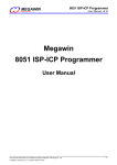
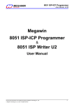
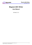
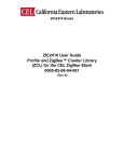
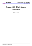
笙泉科技股份有限公司 Megawin Technology Co., Ltd. Megawin 8051 ISP Programmer User Manual By Vincent Y. C. Yu, 2006/04/18 v3.32b Contents 1. Chip Configuration for ISP 2. Install PC-site AP and Driver for the ISP Programmer 3. Use the ISP Programmer 4. Simple Manual for GUI of the ISP Programmer 5. Notice about P3.1 (used as ISP’s DTA) This document information is the intellectual property of Megawin Technology. Megawin Technology Co., Ltd. 1999 All right reserved. QP-7300-03B 1 笙泉科技股份有限公司 Megawin Technology Co., Ltd. 1. Chip Configuration for ISP Tow steps have you enjoy the convenience provided by our ISP function. Step1) Configure ISP-memory to 1K bytes (or 1.5K bytes for MPC82L(E)54 ) and make HWBS option enabled by a Writer or Programmer. (Users may use the “Megawin proprietary 8051 Writer” or the “Hi-Lo ALL-11 Universal Programmer”, refer to the following pages for their simple manual). Step2) Program the Megawin-provided standard ISP code, "ISP_DUT_v4.02.bin" in the [ ISP Code ] folder, into theISP-memory. Note: To let users easily use the ISP feature, from 01/01/2006, the MPC89L(E)51~515 manufactured by Megawin will have the default factory setting: (1) ISP-memory is configured with 1K bytes and “HWBS” option is enabled (2) “LOCK” and “SB” options are enabled So, if your MCU has been configured by Megawin, you have no need to do it by yourself. This document information is the intellectual property of Megawin Technology. Megawin Technology Co., Ltd. 1999 All right reserved. QP-7300-03B 2 笙泉科技股份有限公司 Megawin Technology Co., Ltd. 1.1 Using the “Megawin Proprietary 8051 Writer” Please follow the steps (also shown in the following picture): Step1: Select the Part No. Step2: Select Target Zone: ISP-memory Step3: Load the ISP code: “ISP_DUT_v4.02.bin” Step4: Configure the Option: 1KB, or 1.5KB for MPC82L(E)54, of ISP-memory and HWBS enabled Step5: Click “Program Option” to program the Option Step6: Click “Auto” to program the ISP code into the ISP-memory. This document information is the intellectual property of Megawin Technology. Megawin Technology Co., Ltd. 1999 All right reserved. QP-7300-03B 3 笙泉科技股份有限公司 Megawin Technology Co., Ltd. 1.2 Using the “Hi-Lo ALL-11 Programmer” Step 1. Configure the option: Enable HWBS and select ISP Address (1) (2) (3) (4) For MPC89L(E)51/52/53: select 0x3800-0x3BFF (1K bytes for Megawin-provided ISP code) For MPC89L(E)54/58/515: select 0xF800-0xFBFF (1K bytes for Megawin-provided ISP code) For MPC82L(E)52: select 0x1C00-0x1FFF (1K bytes for Megawin-provided ISP code) For MPC82L(E)54: select 0x3800-0x3DFF (1.5K bytes for Megawin-provided ISP code) See the following example: For MPC89L(E)51/52/53: Select ISP Address Enable HWBS This document information is the intellectual property of Megawin Technology. Megawin Technology Co., Ltd. 1999 All right reserved. QP-7300-03B 4 笙泉科技股份有限公司 Megawin Technology Co., Ltd. Step 2a. Load the “ISP code” to the Programmer’s buffer As the following figure, select “Load File to Programmer Buffer”, and input a file. Now, goto Step 2b. This document information is the intellectual property of Megawin Technology. Megawin Technology Co., Ltd. 1999 All right reserved. QP-7300-03B 5 笙泉科技股份有限公司 Megawin Technology Co., Ltd. Step 2b. Change the “Buff start” to MCU’s ISP start address (1) (2) (3) (4) For MPC89L(E)51/52/53: change to 0x3800 For MPC89L(E)54/58/515: change to 0xF800 For MPC82L(E)52: change to 0x1C00 For MPC82L(E)54: change to 0x3800 Change the “Buff start” This document information is the intellectual property of Megawin Technology. Megawin Technology Co., Ltd. 1999 All right reserved. QP-7300-03B 6 笙泉科技股份有限公司 Megawin Technology Co., Ltd. Step 3. Click the “Auto” button to program the ISP code and Option into 8051 This document information is the intellectual property of Megawin Technology. Megawin Technology Co., Ltd. 1999 All right reserved. QP-7300-03B 7 笙泉科技股份有限公司 Megawin Technology Co., Ltd. 2. Install the PC-site AP and Driver for the ISP Programmer 2-1. Install the AP Run “Setup.exe” (in the [ISP Programmer \ AP ] folder) to install the application program “Megawin 8051 ISP Programmer” on your PC. Using its default installing setting, you will find the item “Megawin Utilities \ Megawin 8051 ISP Programmer (v3.32)” from the Windows’ START-menu. 2-2. Install the Driver Plug the “ISP Programmer” into a PC’s USB port, tell host where the driver “Mega0302_8051ISP_v2.00.inf” is located to install the device driver. (It is located in the [ ISP Programmer \ Driver ] folder.) After the driver is successfully installed, you will see the following page in the “System\Hardware\Device Manager\”. Successfully installed !! This document information is the intellectual property of Megawin Technology. Megawin Technology Co., Ltd. 1999 All right reserved. QP-7300-03B 8 笙泉科技股份有限公司 Megawin Technology Co., Ltd. 3. Use the ISP Programmer 3-1. Introduction The ISP Programmer, as shown below, consists of two main chips, the MPC130 (USB device controller) and the MPC89L516X2 (8051 MCU). The MPC130 functions as a USB bridge, which performs data transfer between MPC89L516X2 and the Host (the PC), while the MPC89L516X2 functions as non-volatile data storage and provides new code to the 8051 MCU in the customer’s system (hereafter, called the Target MCU) for ISP processing. Because the new code can be saved in the non-volatile data storage of the MPC89L516X2, this ISP Programmer is able to work stand-alone without the AP’s intervention. This feature is especially useful in the place without a PC, such as a production line. picture Picture of the ISP Programmer This document information is the intellectual property of Megawin Technology. Megawin Technology Co., Ltd. 1999 All right reserved. QP-7300-03B 9 笙泉科技股份有限公司 Megawin Technology Co., Ltd. 3-2. Operation Mode There are three operation modes for the ISP Programmer: Mode-1: With PC and customer’s system connected: In this condition, the ISP Programmer works with the AP running. Two main buttons can be clicked: the “Update Programmer” button is used to download new code (to be programmed into the Target MCU) into the nonvolatile data storage of the MPC89L516X2, while the “Update Target” button includes the download action and further programs the new code into the Target MCU. Of course, user must select “Part No.” and then “Load File” before clicking the “Update Programmer” or “Update Target” button. Also, the ISP-key can be used to start ISP processing after the “Update Programmer” button is executed. As shown in the following figure, we strongly recommend users to connect the ISP Programmer to PC first, then to customer’s system (which must be powered off ). After connection ok, power on the customer’s system. At this time, the Target MCU is kept reset state and will boot from ISP-memory once its RST-pin is released (by the ISP Programmer). When the Target MCU boots from the ISP-memory, it executes the ISP code, which makes handshaking to the ISP Programmer and will start ISP processing if the handshaking succeeds. If ISP processing succeeds, the green LED is lighted, otherwise the red LED is lighted. Now, user can disconnect the ISP Programmer to let the system start running new code. Customer's System PC ISP Interface ISP Programmer VDD VDD P3.1 VSS DTA VCC DTA GND USB GND MPC89L(E)51/52/53/54/58/515 MPC82L(E)52/54 This document information is the intellectual property of Megawin Technology. Megawin Technology Co., Ltd. 1999 All right reserved. QP-7300-03B 10 笙泉科技股份有限公司 Megawin Technology Co., Ltd. Mode-2: Only PC connected: In this condition, the ISP Programmer works with the AP running and only the “Update Programmer” button can be clicked. User downloads new code (to be programmed into the Target MCU) into the non-volatile data storage of the MPC89L516X2 for later use. PC ISP Programmer VCC DTA GND USB Mode-3: Only customer’s system connected: In this condition, the ISP Programmer works stand-alone without the AP’s intervention. First, connect the ISP Programmer to the customer’s system, which must be powered off. Then, press the ISP-key for ISP processing after the customer’s system is powered on. If ISP processing succeeds, the green LED is lighted, otherwise the red LED is lighted. Now, user can disconnect the ISP Programmer to let the system start running new code. Of course, user can power off the system and then disconnect the ISP Programmer. Customer's System ISP Interface ISP Programmer VDD VDD P3.1 VSS DTA VCC DTA GND GND MPC89L(E)51/52/53/54/58/515 MPC82L(E)52/54 This document information is the intellectual property of Megawin Technology. Megawin Technology Co., Ltd. 1999 All right reserved. QP-7300-03B 11 笙泉科技股份有限公司 Megawin Technology Co., Ltd. 3-3. “USB LED” and “Programmer LED” The “USB LED” will keep “ON” state while the Programmer is successfully connected to host (PC) and no data transfer between the Programmer and the host. The “USB LED” will blink while: (1) data is being downloaded into the Programmer, or (2) the host is waiting for the ISP processing result. Normally, the “Programmer LED” always keeps “ON” except some error happens in the Programmer. Once some error happens, this LED will keep blinking, and now, the only thing the user needs to do is: Disconnect the Programmer from customer’s system and PC, then re-connect to PC to re-download the program data into the Programmer. This document information is the intellectual property of Megawin Technology. Megawin Technology Co., Ltd. 1999 All right reserved. QP-7300-03B 12 笙泉科技股份有限公司 Megawin Technology Co., Ltd. 4. Simple Manual for GUI of the ISP Programmer 4-1. Introduction to the GUI Panel As shown below. This document information is the intellectual property of Megawin Technology. Megawin Technology Co., Ltd. 1999 All right reserved. QP-7300-03B 13 笙泉科技股份有限公司 Megawin Technology Co., Ltd. 4-2. Two Examples Ex. 1: How to download new data (which consist of user’s application code and non-volatile data) into the Programmer? Step 1: Select MCU’s Part No. Step 2: Click “Load File”, both HEX format and BIN format are acceptable, and the code size is based on its binary format. For MPC89L(E)51/52/53, the maximum code size is 15K-1K=14K bytes, which includes IAP data. For MPC89L(E)54/58/515, the maximum code size is 63K-1K=62K bytes, which includes IAP data. For MPC82L(E)52, the maximum code size is 8K-1K=7K bytes, which includes IAP data. For MPC82L(E)54, the maximum code size is 15.5K-1.5K=14K bytes, which includes IAP data. Where, 1K bytes [ or 1.5K bytes for MPC82L(E)54 ] are used by the ISP code. Step 3: Configure the Option Bits. (Only available for MPC89L(E)51~515) Step 4: Click “Update Programmer”. Ex. 2: How to update the MCU’s AP-memory and IAP-memory? (which consist of user’s application code and non-volatile data) Step 1: Select MCU’s Part No. Step 2: Click “Load File”, both HEX format and BIN format are acceptable, and the code size is based on its binary format. For MPC89L(E)51/52/53, the maximum code size is 15K-1K=14K bytes, which includes IAP data. For MPC89L(E)54/58/515, the maximum code size is 63K-1K=62K bytes, which includes IAP data. For MPC82L(E)52, the maximum code size is 8K-1K=7K bytes, which includes IAP data. For MPC82L(E)54, the maximum code size is 15.5K-1.5K=14K bytes, which includes IAP data. Where, 1K bytes [ or 1.5K bytes for MPC82L(E)54 ] are used by the ISP code. Step 3: Configure the Option Bits. (Only available for MPC89L(E)51~515) Step 4: Click “Update Target”. This document information is the intellectual property of Megawin Technology. Megawin Technology Co., Ltd. 1999 All right reserved. QP-7300-03B 14 笙泉科技股份有限公司 Megawin Technology Co., Ltd. 5. Notice about P3.1 (used as ISP’s DTA) The I/O pin P3.1 is now used as the DTA of the ISP interface. Users should pay attention to its normal function and ISP operation to let both them work well. (Of course, the best case is that P3.1 dedicates itself to the ISP operation.) During ISP operation, P3.1 functions for bi-directional data transfer. It may output logic-1 or logic-0, and also, it may receive logic-1 or logic-0 while as input. So, users should consider if the system’s other components will be damaged by this ISP operation. If P3.1 is not dedicated for ISP operation, there is a requirement for P3.1. That is P3.1 must act as an output pin in its normal operation, and meet a little restriction as shown in the following applications. R>=1K, for VCC=5.0V and 3.3V R>=750, for VCC=5.0V and 3.3V VCC VCC 1 8051MCU R_Load R P3.1 PNP 3 3 8051MCU 2 R 2 P3.1 NPN 1 R_Load Input impedance Ri>=10K R>=510 for VCC=5.0V R>=330 for VCC=3.3V VCC 8051MCU VCC LED 8051MCU R P3.1 P3.1 R_pull-up Some Device >=1K, for VCC=5.0V/3.3V Input Ri No restriction for UART function RS232 Transceiver 8051MCU P3.1 UART's TXD Input This document information is the intellectual property of Megawin Technology. Megawin Technology Co., Ltd. 1999 All right reserved. QP-7300-03B 15