1
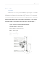
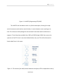
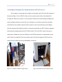
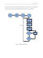
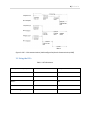
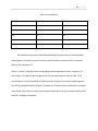
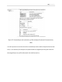
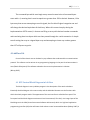
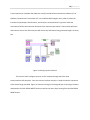
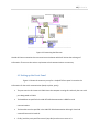
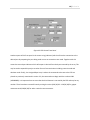
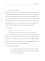
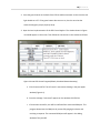
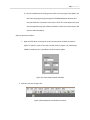
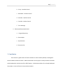
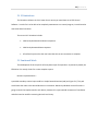
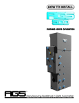
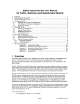
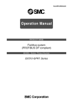
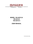
FLORIDA GULF COAST UNIVERSITY
UMI RTX CONTROL V2
LabView 8.2 Serial Communication
By. Jaime Zabala
Mentor. Janusz Zalewski
Spring 2009
2|Zabala
Contents
1. Introduction .............................................................................................................................................. 3
1.1 UMI RTX .............................................................................................................................................. 3
2. Intelligent Peripherals Communications (IPC) Protocol –......................................................................... 5
2.1 The structure of the IPC protocol ....................................................................................................... 6
2.2 Using the IPCs...................................................................................................................................... 8
3. Serial Communication ............................................................................................................................. 11
3.1 How to talk to a serial device ............................................................................................................ 11
3.2The data structure ............................................................................................................................. 12
4. LabView 8.6 ............................................................................................................................................. 13
4.1 RTX Control Block Diagram in LabView ............................................................................................. 13
4.2 Setting up the Front Panel ................................................................................................................ 15
4.3 Controlling the RTX ........................................................................................................................... 17
4.4 User Manual ...................................................................................................................................... 17
4.4.1 How to Operate the Robot in LabView ...................................................................................... 17
4.4.2 How the LabView Software Was Developed ............................................................................. 20
5. Conclusion ............................................................................................................................................... 21
5.1 VI Limitations .................................................................................................................................... 22
5.2 Continued Work ................................................................................................................................ 22
6. References .............................................................................................................................................. 23
3|Zabala
1. Introduction
1.1 UMI RTX
The Robotic arm that I am using is the UMI RTX Robot (Figure 1.1), was first available in
1986, designed with 6 degrees of freedom (Knight, 1999). The number of DOFs (degrees of
freedom) that a manipulator possesses is the number of independent position variables that
would have to be specified in order to locate all parts of the mechanism. In other words, it
refers to the number of different ways in which a robot arm can move (see Figure 1.2):
1. Linear- consisting of a simple up and down movement.
2. Shoulder- allows for rotation of arm.
3. Elbow- allows the rotation of the arm.
4. Wrist- control of yaw
5. Wrist – control of pitch
6. Wrist- control of roll
4|Zabala
Figure 1.1: UMI RTX (Programming RTX,1985)
The UMI RTX was intended to work in a cylindrical workspace, allowing for simple
vertical movements and rotation around its base, it cannot however access anything on its
back. This robot was initially designed to be used with Turbo Pascal which had libraries to
support it. Turbo Pascal was available from 1983 until 1992 (Knight, 1999). One note on the
operation of the RTX is that it must be initialized before every use. This will be discussed in
further detail later in this report.
Figure 1.2: The motion of the UMI (Universal Machine Intelligence) RTX is comparable to that of
a real arm.
5|Zabala
2. Intelligent Peripherals Communications (IPC) Protocol –
The computer is connected to the robotic arm through a serial link from the computer’s
Serial port (Figure 2.1) to a RS-232 socket at the connection panel of the robot (Figure2.2).
Through this cable seen in Figure 3.1, the computer sends binary commands generated by the
control software directly to control the arm. Ultimately, once all the connections have been
made (further set up details may be found in section 5), the communication process begins
with the opening of the COM port which is currently connected to the RTX. A distinct change in
the buzzing sound generated by the RTX will be heard. This is the RTX’s motors turning to a
ready state. All data sent from the COM port to the RTX will be bytes in unsigned byte arrays
which make up commands. These commands come in three byte segments (which must be
passed at once inside a byte array) followed by a response.
Figure 2.1 : Computer COM Port (right cable)
Figure 2.2 RTX RS-232 Serial Jack(top cable)
6|Zabala
2.1 The structure of the IPC protocol
The IPC protocol is multiplexed relating to a system of simultaneous
communication of two or more messages on the same wire or radio channel between two
intelligent peripherals. The IP’s loops fluctuate at 62.5 Hz, meaning that they make a new
demand every 16ms. This period defines the communication time frame and our time limit for
inputting single command series (UMI Intelligent Peripherals Communications, 1985).
The switching between IPs is normally done automatically after a response is sent to the
computer. You can disable the automatic switching by sending a specific command to the
Intelligent Peripherals. This allows you to switch between the IPs manually using another raw
command. Each communication frame begins with single command type byte being sent to IP0.
This byte contains the command type code. It may be followed by two more command bytes if
the whole command cannot be specific in the one byte. The command type code and the
command bytes together form the command.
Example Command Types (X means 1 or 0)
Directive Commands – 10XXXXXX – Initiate movement in manual or numeric modes.
Interpolation Commands - 110XXXXX - Increments a particular motor to its next time segment
The command is then followed by the response which is sent back from IP0 to the
computer. This consists of a single byte containing the response type code, and possibly two
further bytes if the whole response cannot be specified in one byte. The response type code
and the response bytes together form the response.
7|Zabala
The communication link then automatically switches to IP1 as seen in figure 2.4. (assuming the
automatic switching has not been disabled) and then the same process is repeated.
Wiring
Connect
Turn on
Robot /
E-Stop
Initialize
START
Command
Type
Command
Byte 1
Next IP
Command
Byte 2
Rtx
Busy?
Yes
No
Respo
nse?
Yes
Figure 2.3 RTX Operational Flowchart
No
Wait
8|Zabala
Figure 2.4 IPC – CPU communications (UMI Intelligent Peripherals Communications,1985)
2.2 Using the IPCs
Table 2.1 RTX IP1 Motors
Motor (controlled by IP1)
Controller Decimal
Binary Number
Base 1
0
000
Base 2
1
001
Wrist 1
2
010
Wrist 2
3
011
Ultra sonic ranger
4
100
9|Zabala
Table 2.2 RTX IP0 Motors
Motor (controlled by IP0)
Controller Decimal
Binary Number
Elbow
0
000
Shoulder
1
001
Zed
2
010
Yaw
3
011
Gripper
4
100
The individual motors are controlled independently by each series of command bytes,
meaning that if you wish to control 3 motors, you will need to send three sets of command
bytes to the respective IP’s.
Tables 2.1 and 2.2 both show the corresponding motor assignments for their respective IP’s,
while Figure 2.5 shows the bit arrangement for the command bytes as well as order. Each
command sent in manual mode will be directed at the IP which is currently occupied queued.
The RTX Operational Flowchart (Figure 2.3) shows the IP behavior from command to command
more clearly. This pattern of command / response holds true for all serial communications with
the RTX’s intelligent peripherals.
10 | Z a b a l a
Figure 2.5 Command byte order and make up (UMI, Intelligent Peripherals Communications,
1985)
It is also important to note that the entire command byte series needs to be passed at the same
time, i.e. the necessity for the bytes to be placed inside an unsigned byte array (the reason for
the unsigned byte array will be discussed in the LabView section.)
11 | Z a b a l a
3. Serial Communication
Figure 3.1: Serial to RS-232 cable
Serial communications can only transmit data one bit at a time. In theory, this means
that only one signal line and one return line are needed, each sending 1 bit at a time. However,
since our commands and command types are byte segments (which need to be received
together), we need to find a more practical data structure to send a complete command (see RS
232-C standard).
3.1 How to talk to a serial device
The IPC is a handshaking protocol, meaning that within each communication frame a
command is sent to and a response is received from each of the two IPs.
In this case, the handshaking is the synchronized automated process of negotiation that sets
the parameters of the communications channel established between two devices before any
other communication or data transfer can begin.
12 | Z a b a l a
In order to set up the correct handshaking relationship, not to mention any form of successful
communication, the computer must know certain parameters for data transfer unique to the
device being controlled.
Port – the port to which the device is connected.
Baud rate – essentially the bit transfer rate or how many bits are passed every second.
Data bits – the number of data bits to be passed per signal
Parity – simple error detecting, ensures that the bits are either even or odd.
Stop bits- not necessary for synchronous serial communication
3.2The data structure
As mentioned previously, the serial connection ensures that each command is passed 1
bit at a time. So this means that each command is put together by the computer, taken apart,
transmitted through the RS 232 serial cable, and reassembled by the RTX. When the RTX has
received an entire command series, the bits will be reassessed as bytes and reordered to
associate with a certain action. In order for the RTX to assess the entire command series as one
unit, the CPU must pass it as one unit which can be broken down into bytes and then to bits. A
byte array is ideal for this purpose because it consists of a relatively simple structure which is
capable of serial transmission under the RS 232-C standard. More over, an unsigned byte array
is necessary for our purposes because of what we intend to pass through the serial connection.
Remember the manual transmission bit segment in Figure 2.2?
13 | Z a b a l a
The command byte which must begin every manual transmission of command bytes
starts with a 1, meaning that it must be equal to or greater than 128 in decimal. However, if the
byte array that we are attempting to send is signed, the first bit will signal a negative one and
will change the decimal equivalent of the binary. Where this comes into play during the
implementation of RTX control, is that we are filling an array with decimal number commands
and translating them into bytes which are then passed through the serial connection. A simple
test of setting the array to a signed byte array and attempting to insert any number greater
than 127 will prove my point.
4. LabView 8.6
Control of the robotic arm can be done by any software that understands the communications
protocol. This software can be written in any programming language. In the past it has been written in
Java (Zabala & Bejerano).The software selected to the current implementation is Labview
(Bishop,2007).
4.1 RTX Control Block Diagram in LabView
The block diagram in every LabView program is the description of the work to be done.
Essentially the block diagram is the source code, and the individual elements are the functions with
which the whole program works. The appearance of the user interface is called the front panel. The
front panel and the block diagram constitute a Virtual Instrument (VI for short). An integral part of the
block diagram is the VISA (Virtual Instrument Software Architecture) which is a high level application
programming interface (API) that calls lower-level code to control connected hardware (Bishop, 2007). It
14 | Z a b a l a
is also important to remember that VISAs are actually considered instrument driver software (VI’s in
LabView). Located under “Instrument I/O” in the LabView Block Diagram menu, VISA VI’s allows for
Instrument input/output, GPIB functions, and Serial port communications. Figure 4.1 shows the
connection of all the communication elements to the VISA serial port which is then used to define the
VISA resource name. This VISA serial port will convert any information being passed through it to binary
bits.
Figure 4.1 Setting up the VISA Serial
The resource name configures the port on the computer through which the serial
communications will take place. Once the resource has been named, it is used to make the connection
to the device being controlled. Figure 4.2 shows the wiring for the unsigned byte array being translated
and passed to the VISA SERIAL WRITE function as well as the return bytes coming from the VISA SERIAL
READ function.
15 | Z a b a l a
Figure 4.2 Connecting the Elements
Outside all these connections there must exist a write button which will initiate the exchange of
information. There must also exist a stop button to halt communications as necessary.
4.2 Setting up the Front Panel
Figure 4.3 shows the necessary set up for a simple RTX front panel. It contains the
information for the serial communication (baud, stop bits, parity).
•
The port name in this instance is COM1 since the computer running this code only has one serial
port designated as COM1.
•
The Baud Rate as specified in the UMI RTX 100 Documentation is 9600 for serial
communications.
•
The Data bits are also specified in the UMI RTX 100 documentation although I have had
successful tests with 10 and 16.
•
Finally, both the parity and flow control (stop bits) must be set to none or 0.
16 | Z a b a l a
Figure 4.3 RTX Control Front Panel
Another aspect of this front panel is the return string (indicator) which confirms the connection to the
desired port by outputting the port being used as soon as connections are made. Together with this
comes the return bytes indicator which will output in decimal form the bytes returned by the array. This
may be used to expand this project to other forms of communication including numeric mode and
absolute mode. Finally, the Unsigned Byte Array is where the commands to be sent to the RTX are
placed. As previously mentioned in section 3.2, the command must begin with the number 128d
(10000000b). It is important here to stress that the third element is not read by the RTX and may be any
number. There have been successful tests by writing the series (128|16|03 – 128|32|03) for gripper
movement and (128|64|03) for zed or vertical motor movement.
17 | Z a b a l a
4.3 Controlling the RTX
Since the final goal is after all to control the RTX robot using LabView controls, more work will have to
be put toward the stand alone capabilities of the LabView RTX Control VI. As previously mentioned in
section 1, the UMI RTX requires initialization before it may be used (only if previously power off). For
this, one can use the existing Java Code which contains a connect and initialize (home) function within
(Zabala, Simulated Human Anatomy). After the initialization is complete, the Java applet may be shut
down and the RTXControl.VI may be run and executed without a problem. It is also important to note
that there is a C++ library available online with a similar executable for initializing the RTX.
4.4 User Manual
4.4.1 How to Operate the Robot in LabView
In order to be able to operate the RTX robot, there are some critical points that must be
observed. Firstly, the RTX must have a null signal coming from the external Emergency Stop, which may
be a plug connecting an unengaged “STOP” button or simply a serial connector leading to nothing(see
the D-9 connector next to the lights in Figure 2.2). Secondly, the RTX to computer communications will
always need to be initialized before use. Thirdly, the robot must be homed or zeroed back to a starting
position before use. This serves as a zero point for all numeric positions.
Steps to begin communications with RTX –
1. Be sure that both computer and RTX are powered on. A red light should be on in the
back panel of the RTX (see Figure 2.2). The RTX power switch is located on the back
panel, just above the power cable plug.
18 | Z a b a l a
2. Press the green button on the back of the RTX to enable movement. At this time the red
light should turn off. If the green button does not turn on, then be sure that the
external emergency stop is properly setup.
3. Open the Java implementation of the RTX Control Applet . The window shown in Figure
4.4 should appear on the screen. Then follow the instructions in this window as follows.
Figure 4.4 Java RTX Control Program(Zabala, Simulated Human Anatomy)
a. Click Connect to RTX. This will result in new status showing in the java applet
window (Figure 4.4)
b. Once the message “connected” appears on the window click RTX ON.
c. If connection successful, user will be notified of the connected COM port. This
program determines the COM port by successfully pinging the device and
receiving a response. The connected COM port will appear in the debug
window of the java IDE.
19 | Z a b a l a
d. Close the window by left clicking on the red X on the top right of the applet. DO
NOT close the program by pressing the EXIT PROGRAM button because that
may shut down the connection to the robot. NOTE: This same objective may be
also accomplished using the software available on the Internet (see Wayne, RTX
Libraries and Executables)
Steps to Operate the Robot 1. Open the RTX Write VI and set the serial communication variables as shown in
Figure 4.5 (which is a part of the user interface shown in figure 4.3), substituting
COM1 for whatever port is specified in the RTX Control Applet.
Figure 4.5 Serial Communication Variables
2. Click Run as shown in Figure 4.6.
Figure 4.6 Run Operation in LabView Front Panel
20 | Z a b a l a
3. Enter a series of decimal numbers in the allocated spaces labeled “Array” following the
RTX’s intelligent peripherals protocol. You may use the test sequence from section 4.2.
4. Press the “Write” button. The robot arm should move as programmed.
5. Allow for the RTX to complete its full movement before entering another command. If
not the RTX queue may be filled and overload the computer.
6. Press “STOP” to terminate the RTX robot’s operation.
4.4.2 How the LabView Software Was Developed
The development of the LabView VI titled RTX Write came from the idea that we can talk to
another computer using the hyper terminal. In order to do this, we had to be able to effectively use VISA
VI’s to establish communications. Once this was done, we would pass strings to it which would in turn
be turned to binary for the trip to the connected computer. This RTX VI uses these same principles to be
able to communicate with the robot.
RTX Design Principles (From Block Diagram Figure 4.1 and 4.2) –
1. Setup communication components for external device
a. VISA Configure Serial Port
b. Resource Name In / Resource Name Out
c. VISA Serial Write / VISA Serial Read
2. Setup RTX control parameters
a. Port Name - String Control
21 | Z a b a l a
b. Parity – Number Control
c. Baud Rate – Number Control
d. Data Bits - Number Control
e. Stop Bits - Number Control
f.
Error Message
3. Setup input/output parameters
a. Unsigned Byte Array
b. Return Bytes
c. Bytes Written
d. Resource Out
5. Conclusion
There remains a good amount of work to be done in order to wholly develop a working RTX
Control LabView Virtual Instrument. What has been done in this project is merely the basis and needs
to be broadened to include more of the RTXs features. A LabView translation of an already developed
Java project, in terms of structure may also be an option.
22 | Z a b a l a
5.1 VI Limitations
The limitations inherent in this VI mean that it cannot yet stand alone as an RTX Control
Software. In order for it to be able to be completely autonomous as a control program, it would need to
overcome these limitations.
The current VI’s limitations include:
•
LabView implemented initialization sequence
•
LabView implemented home sequence
•
A feed back system to let the user know that the current movement is complete.
5.2 Continued Work
The development of this simple VI left many doors open for expansion. As previously stated, the
RTX Write VI is merely a basis for a more complete system.
Numeric Implementation –
A possible secondary motion input could be a simple button directional pad (see Figure 5.1). This pad
would move the robot in the desired direction in increments. Obviously individual control of motors is
going to need to be implemented in each button, however this system would increase user friendliness
and eliminate the need for converting decimal intro binary.
23 | Z a b a l a
Figure 5.1 Possible Numeric and Cluster Implementation
Cluster OutputAn excellent way to signal that a movement is done executing would be through Boolean LED’s
(Figure 5.1). By implementing a cluster either as a Boolean array or with the individual motors returning
an on/off signal, it is possible to easily check for a completed movement. Essentially, if all lights on the
LED are off, then the user may enter another command.
6. References
Bishop, R. (2007, January) LabView 8 Student Edition.
Knight, G. (1999, June 18). UMI ROBOT USER AND PROGRAMMER’S MANUAL. Retrieved
24 | Z a b a l a
from Computer Systems Design:
http://services.eng.uts.edu.au/~carlo/pdf/Hitsquad_Robot_Manual.pdf
Universal Machine Intelligence Limited (1985, November) Using Intelligent Peripherals Communications.
Universal Machine Intelligence Limited (1985, November) Programming RTX.
Wayne, S. RTX Libraries and Execuatables
http://www.staffs.ac.uk/personal/engineering_and_technology/sow1/Robotics/RTX/rtx.htm
Zabala, J., & Bejerano, F. (2008, April). RTX Control Applet.
Zabala, J., & Bejerano, F. (2008, April). Simulated Human Anatomy.