1
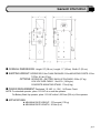
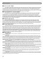
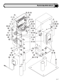
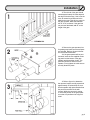
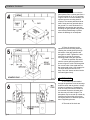
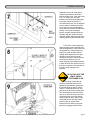
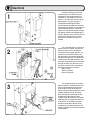
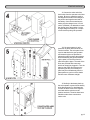
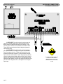
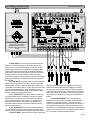
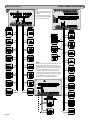
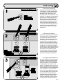
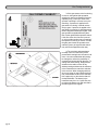
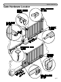
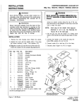
pg 1 Contents Page General Information...........................................................................................................3-4 Features...............................................................................................................................5-6 Parts Identification..............................................................................................................7-8 Installation.........................................................................................................................9-11 Electrical..........................................................................................................................12-16 Fine Tuning.......................................................................................................................17-18 Master/Slave........................................................................................................................19 Wiring Diagrams..............................................................................................................20-24 Safety Edge..........................................................................................................................25 Options............................................................................................................................26-27 Maintenance & Safety........................................................................................................28 Troubleshooting...............................................................................................................29-31 Notes......................................................................................................................................32 IMPORTANT INSTALLATION INSTRUCTIONS WARNING-To reduce the risk of severe injury or death: 1) READ AND FOLLOW ALL INSTALLATION INSTRUCTIONS. 2) Make sure that the gate is properly installed. An improperly installed door could cause severe injury. Have a qualified service person make repairs to the gate and other hardware before installing the opener. 3) Do not connect the opener to source of power until unstructed to do so. 4) Locate the control button: (a) within sight of the door, (b) at a minimum hight of 5 feet so small children cannot reach it, and (c) away from all moving parts of the door. pg 2 General Information m OVERALL DIMENSIONS: Height: 23" (58 cm) Length: 11" (28 cm) Width: 8" (20 cm) m SHIPPING WEIGHT: OPERATOR:53 lbs CHAIN PACKAGE:12 lbs MOUNTING POSTS:16 lbs TOTAL: 81 lbs (37 kg) OPTIONS: OPERATOR + BATTERY BACK-UP PACKAGE: 59 lbs (27 kg) LOW VOLTAGE CABLE: 1 lbs/10 ft (.149 kg/m) CONCRETE MOUNTING STAND: 17 lbs (8 kg) m POWER REQUIREMENT: Dedicated 115 VAC (+/- 10V) , 5A Power Circuit NOTE: For standard operator, place 115 VAC at or near the operator. For Battery Back-Up operator, place 115 VAC within 1,000 feet (305 m) of the operator. m APPLICATIONS: l MAXIMUM GATE WEIGHT: 375 pounds (170 kg) l MAXIMUM GATE LENGTH: 20 feet (6 m) pg 3 General Information m INCLUDED WITH OPERATOR: Check package to make sure it contains the following items. STANDARD GATE OPENER l 1-Model AGS 900 gate operator l 2-Mounting Posts 2" Diameter x 30" l 2-Gate/Chain Brackets, U-Bolt type l 2-U-Bolts Round l 2-U-Bolts Square l 1-Chain #41 x 25 ft l 2-Master Links #41 l 2-Chain Bolts l 2-Self Tapping Screws l 1-Hex Key for Cover l 2-Manual Release Keys BATTERY BACK-UP ONLY l 1-Burial cable, 10 ft l 1-Charger, 12 Volt l 1-Battery, 12 Volt (installed) SOLAR ONLY l 3-Pipe sections, 1" X 24" l 2-Pipe couplings, 1" l 1-Solar Panel Assembly l 5-Lock Rings l 2-Batteries, 12 Volt (installed) (See parts identification.) m POWER REQUIREMENT: There are three possibilities for supplying power to the AGS 900 gate operator. The standard power supply version is made to connect directly to 115 Volt, 5 Amp power source and is available for standard capability and full systems capability models. This power supply must be at or near the gate operator location. Because of the low current draw, 115 Volt power may be run as far as 1000 feet with 12 gauge wire from the main breaker panel and can be run much farther with larger wire. Another possibility for supplying power to the operator is with the low voltage battery back-up version of the AGS 900. To supply power to the AGS 900 battery back-up, wire as small as 16 gauge can be run as far as 300 feet from a charger that is plugged in remotely. Because the power is low 12 Volt DC, the wire can be direct burial wire which eliminates the need for expensive conduit runs. The other possibility for supplying power to the AGS 900 is with the Solar power version of the operator. The Solar model does not require any power to be run because the operator and solar power supply are self contained. The panel may be placed several hundred feet from the operator if this is necessary to achieve maximum sunlight conditions. m MOUNTING: There are two ways to mount the AGS 900 operator. One way to mount the operator is to attach it with bolts to a concrete surface using the optional concrete mounting stand and sleeve anchors. In some cases there will already be an existing concrete surface or pad available to bolt the operator to. If there is no existing concrete surface or pad, it is very easy to fashion one so that the operator can be bolted down at a later time using sleeve anchors. The other way to mount the AGS 900 operator is directly into the earth with the two 2" X 30" mounting posts that have been provided. For this installation the posts are attached to the operator, one post hole is made in the earth and then the operator with posts attached is set in place. The cement can then be poured into the post hole and will dry within minutes if concrete accelerator is used. The operator can be put into full operation the very same day. pg 4 Features STANDARD AND FULL SYSTEMS CAPABILITY m SENSITIVITY As with other AGS gate openers, the AGS 900 has a built-in safety feature which when adjusted properly will deliver only enough power to the motor to overcome the resistance of the gate. What this means is that if the gate runs into a vehicle or pedestrian, the gate will immediately stop or reverse. This "gate sensitivity" feature is unique from others because it functions while the gate is both opening and closing. Because of the DC motor technology incorporated into the AGS 900, the sensitivity feature is much more sensitive and is at least 50% more effective than traditional AC current sensors. m SOFT START/SOFT STOP A unique feature of the AGS 900 is the Soft Start/Soft Stop feature. Traditional gate openers will begin opening the gate with full power causing a yanking or jerking effect that severely decreases the life of mechanical parts. The AGS 900 will begin opening or closing the gate very slowly and will gradually increase to full speed. This creates a very gentle gate translation which considerably reduces the amount of wear and tear on all mechanical parts. m MANUAL RELEASE KEY SWITCH This simple on-off key switch is built into the side of the operator. In an emergency, even with the power off, the gate can be pushed open manually after turning the key counter-clockwise. m ELECTRONIC BRAKE Traditional gate openers typically have a mechanical brake or clutch which requires special maintenance. The DC motor technology that is incorporated into the AGS 900 provides the gate opener with a brake that will never wear out. This patented feature causes the gate to come to a stop and keeps the gate locked when stopped in any position. m BATTERY BACK-UP/LOW VOLTAGE The AGS 900 is available in both battery back-up and solar versions. The main and most obvious benefit to having battery back-up or solar is the ability to open and close the gate even when there is no power. This in itself provides an extremely high level of convenience. If there is a power failure the gate will operate as it normally does and can be opened up to 150 times before power is restored. Another very important benefit to having battery back-up is that it is not necessary to have 115 Volts at the operator location because running high voltage is typically very expensive and highly regulated. All that is needed to supply power to a battery back-up version of the AGS 900 is some inexpensive low voltage burial cable. If the cable is 16 gauge it can be run as far as 300 feet. For solar versions of the AGS 900, no power needs to be run to the operator. The solar version has a solar panel which is normally attached to the gate opener but can placed anywhere that allows the panel to receive maximum sunlight. m STANDARD CAPABILITY INPUT FUNCTIONS The standard capability circuit board has two input functions, open and stop. Both inputs require normally open contacts. The open input function is used to both open and close the gate and the stop input function is used to interrupt the gate while it is running and bring it to a stop. Stop input can also be used as a simple safety input to stop the gate before contacting a vehicle or pedestrian. FULL SYSTEMS CAPABILITY ONLY m VISUAL FEEDBACK The AGS 900 Full Systems Capability circuit board has been equipped with visual feedback LED's (small indicator lights) to help simplify installation and troubleshooting. There are LED's located directly beside each input terminal to indicate if any input devices are active. There are also two LED's which indicate that the circuit board is delivering power to the motor and are labeled O and C for either the Opening or Closing directions of travel respectively. Collectively, all of the LED's combined provide quick glance information to the installer or service technician showing visually what is happening in the normally invisible operation of the circuit board. pg 5 Features continued... m AUTO CLOSE TIMER The operator comes factory preset with the auto close timer function OFF. The auto close timer will close the gate automatically after a specific amount of time has elapsed. The amount of time can be easily adjusted between 0 and 45 seconds by turning a small "pot" located on the edge of the circuit board (See page 17). The timer can be disabled or activated by flipping a single switch located on the top edge of the circuit board. If the timer will be used it is recommended that some type of supplementary safety device (loops, photo beam etc.) be installed. m GATE SENSITIVITY ADJUSTMENT The amount of force necessary to stop the gate can be adjusted to conform to the various sizes and weights of any particular gate. The full systems capability circuit board provides separate adjustments for both the opening and closing direction. When adjusting the sensitivity, the operator can be given only as much energy as is necessary to overcome the resistance of the gate. If the gate should strike an obstruction in the closing direction, the gate will reverse to the open position. If the gate should strike an obstruction in the opening direction, the gate will stop and remain stopped until commanded to return to operation. (See page 17) m MASTER AND SLAVE Some very large entrances may require the use of two gates. If this is the case, the two gates can be easily automated using the "master and slave" configuration. This configuration uses two gates and two operators in ONE driveway. Although models equipped with standard capability can be connected as master and slave, they may not always give satisfactory performance and may not work simultaneously. Full systems capability models have terminals provided especially for master and slave applications and will reliably operate simultaneously all of the time. m PULSE OPEN INPUT The Pulse Open input feature is an open input on the circuit board which will increase the security of the AGS 900 gate operator system. When an open input device such as a radio receiver is connected to the Pulse Open input, and the radio transmitter is pressed, the gate operator will activate but will then ignore the input if the input is prolonged. What is significant about this feature is that there is the possibility of a transmitter button being stuck and if the radio receiver is connected to the standard open input the gate will be held open. If the radio receiver is connected to the Pulse Open input on terminals 6 and 7, the circuit board will ignore the stuck input and will allow the gate to close. The pulse open input is designed for but not limited to a radio receiver. For added security any open input device may be used with Pulse Open including push buttons, key switches, numerical key pads etc. m PERIPHERALS POWER SUPPLY: There is 12 Volts DC .1 AMP available on the circuit board which is used to supply power to a radio receiver or other device. OPEN INPUT: Normally open devices are connected to terminals 5 and 6 on the circuit board to cause the gate to open and/or close in PUSH-TO-OPEN/PUSH-TO-CLOSE (Timer switch OFF) mode of operation. Normally open devices are connected to terminals 5 and 6 to cause the gate to open in AUTO CLOSE TIMER (Timer switch ON) mode of operation. In this mode of operation the AUTO CLOSE TIMER will automatically close the gate after a specific amount of time has elapsed. The Auto Close Timer is adjustable between 0-45 seconds. These normally open devices can be push buttons, radio receivers, key switches, loop detectors, photo electric beams, 24 hour timers, etc. See FEATURES on the next page for other open input capabilities. PULSE OPEN INPUT: Normally open devices are connected to terminals 6 and 7 on the circuit board to cause the gate to open. Pulse Open Input functions identical to Open Input with the exception that it will not hold open the gate. If a transmitter or other open device is stuck on, the gate will still close. This feature is sometimes used to provide a higher level of security but should be used only in addition to another open device connected to Open Input so the gate can still be opened if necessary. SAFETY INPUT: Normally open devices are connected to terminals 4 and 6 on the AGS 900 circuit board to cause the gate operator to open and/or hold the gate open in any position except the fully closed position. Normally open safety input devices that can be used are push buttons, radio receivers, key switches, loop detectors, photo electric beams, 24 hour timers, etc. N.C. STOP INPUT: Normally closed devices are connected to terminals 8 and 9 on the circuit board after removing the stop jumper that is on terminals 8 and 9. The N.C. Stop Input will cause the gate to stop at any position and will remain stopped until activated to open or close. N.O. STOP INPUT: Normally open devices are connected to terminals 9 and 11 to cause the gate to stop in any position until the gate is again activated to open or close. N.O. Stop Input functions identical to N.C. Stop input with the exception that it requires normally open contacts instead of normally closed contacts. CLOSE INPUT: Normally open devices are connected to terminals 9 and 10 on the circuit board to cause the gate operator to close the gate when in any position. Normally open input devices that can be used are push buttons, radio receivers, key switches, loop detectors, photo electric beams, 24 hour timers, etc. pg 6 Parts Identification pg 7 Parts Identification continued... PART # QNTY. 001 002 003 004 005 006 007 008 009 010 011 012 013 014 015 016 017 018 019 020 021 022 023 024 025 026 027 028 029 030 031 032 033 034 035 036 037 038 039 040 041 042 043 044 045 1 1 2 1 1 1 2 1 1 3 3 1 1 2 4 6 6 1 2 2 1 1 4 4 1 8 1 1 1 2 15 15 15 4 7 1 1 2 1 1 1 1 1 1 4 pg 8 QNTY. SUBSTRATE (FRAME) BEARING PLATE SIDE PLATE COVER FIRE WALL GEAR MOTOR, 12 VDC LIMIT NUT SPROCKET, DRIVE 41B9, 1/2" BORE BUSHING, DRIVE SHAFT 1/2" BORE BOLT, HEX HEAD, 5/16"-18 X 3/4" WASHER, SPLIT RING, 5/16" ID LIMIT GUIDE PLATE LIMIT SWITCH MOUNTING PLATE LIMIT SWITCH SCREW, PAN HEAD PHILLUPS, 6-32 X 1" SCREW, SOCKET HEAD CAP, 10-32 X 5/8" LOCKNUT, 10-32 STAR LOCK, HEX SCREW, SOCKET HEAD CAP, 10-32 X 1" LIMIT PLATE COMPRESSION SPRING LOCKNUT, 8-32 NYLON INSERT, HEX TRANSFORMER (115 V MODELS ONLY) CONTROL BOARD (FULL SYSTEMS OPTIONAL) HEX STANDOFF, 6-32 X 1/2" F/F HEX STANDOFF, 6-32 X 1" M/F (FULL SYSTEMS ONLY) PLEXI GLASS COVER (FULL SYSTEMS ONLY) SCREW, 6-32 X 3/8" PAN HEAD PHILLUPS SPROCKET, IDLER 41B11 3/4" BORE BUSHING 5/8" BORE HEX BOLT 5/8" HEX JAM NUT 5/8" WASHER, FLAT 3/8" ID WASHER, SPLIT RING 3/8"ID NUT, 3/8"-16 U-BOLT, ROUND HEX BOLT, 3/8"-16 RESISTOR, 1 OHM HEX BOLT, 5/16"-18 X 3" FIBER WASHER 3/8" ID HEX NUT, 5/16"-18 BRIDGE RECTIFIER, 35 AMP, 800 VOLT LOCK NUT, 8-32 STAR LOCK, HEX CIRCUIT BREAKER, 1.5 AMP KEY SWITCH, MANUAL RELEASE RECEIVER ENCLOSURE SCREW, PAN HEAD PHILLUPS, 10-32 X 1/2" PART # QNTY. 046 047 048 049 050 051 052 053 054 055 056 057 058 059 060 061 062 063 064 065 066 067 068 069 070 071 072 073 074 075 076 077 078 079 080 081 082 083 084 085 086 087 088 089 090 3 4 2 1 2 1 4 1 1 1 1 1 2 1 2 2 1 1 1 1 1 1 1 1 1 1 4 3 QNTY. PLUG 1-3/8" PLUG 5/8" PLUG 7/16" CONDUIT FITTING, 90 DEGREE FLEX MOUNTING POST, 2" DIAMETER MOUNTING STAND FOR CONCRETE (OPTIONAL) SLEAVE ANCHOR, 3/8" X 3" RADIO RECEIVER (OPTIONAL) FLOAT CHARGER (OPTIONAL) BURIAL CABLE (OPTIONAL) GATE/CHAIN BRACKET (RIGHT) GATE/CHAIN BRACKET (LEFT) CHAIN BOLT CHAIN #41 MASTER LINK #41 SELF TAPPING SCREW (FOR GATE BRACKET) SCREW, SOCKET HEAD CAP (FOR COVER) NYLON WASHER 3/8" ID FOR COVER SCREW ALLEN WRENCH, 5/16" AGS 900 LOGO, DIE CAST ZINC STICKER, WEATHER STICKER, CAUTION STICKER, FLAG BATTERY BACK-UP AND SOLAR BATTERY, 12 VDC (2 FOR SOLAR) BATTERY/RECEIVER ENCLOSURE SOLAR PANEL SOLAR PANEL MOUNTING POSTS MODULAR ELECTRICAL CONNECTORS Installation m The tail end of the gate should extend approximately 18 inches beyond the edge of the driveway. If this is not the case, an extension tail will need to be added to the gate. This will give room for the gate operator. Make the extension tail 18" X 18" as shown. If the gate has not yet been fabricated, add 18" to the length of the gate. m Remove the gate operator from it's package and make sure that all parts are included. Refer to General Information and Parts Identification. m If the gate operator will be post mounted, insert the two supplied mounting posts into the bottom of the gate operator and through the u-bolts. The posts should insert 5 inches into the operator. Firmly tighten the u-bolt nuts to securely fasten the posts. m Refer to figure 3 to determine the operator location and dig a post hole approximately 25 inches deep or more. Set the operator with posts attached into the post hole and fill the hole with cement. While the concrete is setting, re-check the position of the gate operator so that it is positioned as in figure 3 at left. pg 9 Installation Continued... ALTERNATIVE m If it is preferable to mount the gate operator onto a cement pad, form a cement pad that is 14" by 16" as shown in figure 4 at left. For this installation, an optional concrete mounting stand is required. The cement pad should be at least 6" deep and may protrude above the ground 4" or more as shown if it is desirable to elevate the gate operator. Elevating the gate operator may prevent unnecessary flood damage in places where the drainage is not adequate. m Place the operator on the optional concrete mounting stand by inserting the vertical pipes up through the bottom of the gate operator and through the u-bolts. Tighten the u-bolt nuts firmly to secure the concrete mounting stand to the gate operator. m Place the operator with stand onto the cement pad and position it as shown in figure 5 at left. Drill through the four corner holes of the stand and into the cement pad using a 3/8" masonry bit. The holes should be at least 3-1/2" deep. Drive 3/8" sleeve anchors into the holes and tighten firmly. ALTERNATIVE m The chain may be threaded through the sprockets in one of two ways as shown at left and the choice is simply a matter of preference. Threading the chain one way will make the chain low as it extends across the driveway and the other way will make it higher. The side plates may be moved up or down by loosening the nuts which secure them, moving the plate to it's alternate position, then re-tightening the nuts. m The ends of the chain are pg 10 Installation continued... attached to each end of the gate by using the gate brackets and chain bolts as shown at left. If the gate frame is 2" X 2" square tube, the gate brackets may bolted to the gate using the square u-bolts as shown. For round tubular frames, use the supplied round u-bolts for attaching the brackets. In this case use the self tapping screw which prevents the bracket from shifting. For irregular sized gate frames, the gate brackets should be welded to the gate. Attach the chain ends with master links and tension the chain by tightening the chain bolt nuts. m The limits of travel determine where the gate stops in both the open and closed positions. These limits may be adjusted very closely without any power to the gate operator. Before making these adjustments, the gate operator may be put into manual release by turning the manual release key switch as shown at left. This allows the gate to be pushed manually in either direction. Be careful not to run the limit nuts past the limit switches as this may cause damage to the switches. DO NOT ADJUST THE LIMITS WHILE THE POWER IS ON m The limits of travel are adjusted by positioning the limit nuts against the limit switches (pressing in the switch) while the gate is open or closed. To adjust the limit nuts, first push down on the limit nut guide plate. This allows the limit nuts to be freely spun up or down the screw. One limit nut should press in one limit switch when the gate is open, and the other nut should press in the other switch when the gate is closed. When finished, be sure that the limit guide plate firmly engages both limit nuts. pg 11 Electrical m Before making any electrical connections be sure that the power is switched off. If the gate operator is a standard 115 Volt model, run conduit from the 115 Volt power source into the gate operator. The gate operator is provided with a 90 degree flexible conduit fitting for installations where the electrical box is relatively close. Because of the 90 degree fitting, it is generally easier to run the electrical wires through the flexible conduit before attaching the conduit. Wiring for other devices such as push buttons may also be run at this time either in the same conduit or in another. m If not already done, run three 12 gauge wires (hot, neutral, and ground) from the power source, through the conduit and into the gate operator. It is easiest to run these wires back out of the large hole in the operator along with the three existing wires. This allows the connections to be made externally and then later inserted back into the operator through the large hole. Be sure to use wire nuts to secure these connections. Make the connections as follows: Black to (hot) White to (neutral) Green to (ground) m If the gate operator is a battery back-up model, it is packaged from the factory with the battery disconnected. Connect the red wire to the positive battery terminal and the black wire to the negative battery terminal. There are wires provided for connecting the low voltage burial cable from the float charger to the gate operator. The burial cable may be run through the knock-out in the bottom of the battery enclosure and then connected to the two wires provided. Be sure that the positive and negative match the positive and negative of the charger. pg 12 Electrical continued... m Connect the other end of the burial cable from the operator to the float charger. Be sure to match the positive and negative terminals of the charger to the positive and negative terminals of the battery. Once the connections are made, plug the charger into a 115 Volt outlet. If possible, it is desirable to locate the charger out of the weather. Let the charger charge the battery for a couple of hours before putting into operation. m If the gate operator is solar powered, no power will need to be run into the machine. The solar panel is set up to be attached to the gate operator and extension pipes are provided to elevate the panel up above the operator. While assembling the pipes and attaching the panel, run the wires from the panel through the pipes. The ends of the wires are provided with connectors which can simply be plugged in. Turn the panel so that it will get maximum sunlight during the day. If necessary the panel may be mounted away from the gate operator to get it out of the shade and into more consistent sunlight. m Similarly to the battery back-up, the solar operator comes with the battery wires disconnected. For both batteries, connect the black wires to the negative terminals and the red wires to the positive terminals. The wires have been labeled to make these connections easier to do. pg 13 Electrical continued... 7 m OPEN INPUT: Any device that is used to open the gate from a closed position is an open input device. The device used must provide normally open contacts. These normally open contacts are connected to terminals 4 and 5. These open input terminals will cause the gate operator to open and/or close. m STOP INPUT: Any device that is used to stop the gate operator while it is running in the open or closed directions is a stop input device. These stop input devices must provide normally open contacts. To connect these normally open contacts, use terminals 7 and 8. Stop input may also be used for simple external safety devices which can be used to stop the gate when there is a vehicle or a pedestrian present. When the gate operator is told to stop using the stop input, the gate will remain stopped until it is told again to run using the open input. pg 14 ACCESSORY CONNECTIONS STANDARD CAPABILITY TO AVOID POSSIBLE INJURY OR DAMAGE TO EQUIPMENT DO NOT MAKE ELECTRICAL CONNECTIONS WHILE POWER IS ON ACCESSORY CONNECTIONS FULL SYSTEMS CAPABILITY Electrical continued... 8 TO AVOID POSSIBLE INJURY OR DAMAGE TO EQUIPMENT DO NOT MAKE ELECTRICAL CONNECTIONS WHILE POWER IS ON m OPEN INPUT: Any device that is used to open the gate from a closed position is an open input device. The device used must provide normally open contacts. These normally open contacts are connected to terminals 5 and 6. These open input terminals will cause the gate operator to open and/or close if the timer switch is in the OFF position. If the timer switch is in the ON position, these open input terminals will cause the gate operator to open and will hold the gate open until the input is released and the hold open time has elapsed. m CLOSE INPUT: Any device that is used to close the gate is a close input device. The device used must provide normally open contacts. These normally open contacts are connected to terminals 9 and 10. These close input terminals will cause the gate operator to close the gate any time the gate is in a non-closed position and can be used to override the timer and close the gate prematurely. m N.C. STOP INPUT: Any device that is used to stop the gate operator while it is running in the open or closed directions is a stop input device. These stop input devices must provide normally closed contacts. To connect these normally closed contacts, remove the stop jumper from terminals 8 and 9 and then connect the contacts to these same terminals 8 and 9. m N.O. STOP INPUT: This input functions identical to N.C. Stop with the exception that it requires normally open contacts. These contacts are connected to terminals 9 and 11. m SAFETY INPUT: Any device that is used to open and/ or hold open the gate while the gate is in a non-closed position is a safety input device. The safety input device must provide normally open contacts. These contacts are connected to terminals 4 and 6. This function is especially useful when the auto close timer is being used in preventing the gate from accidentally closing on a pedestrian or vehicle. m PULSE OPEN INPUT: The pulse open input terminals were put on the circuit board as an alternative connection for the radio receiver. This input functions similarly to the standard open input with the exception that it will not hold the gate open if the input remains present. This feature will add additional security to the gate operator system in the event that there is a transmitter that is stuck on. Pulse open is found at terminals 6 and 7. pg 15 OTHER COMMON ACCESSORIES Electrical continued... 9 NOTE: All open and safety devices muse provide normally open contacts. For devices requiring power, refer to the specific diagram for that particular device. NOTE: Because on the standard capability circuit board open and close are the same, a vehicle open device must be connected so that the device can only activate the gate when it is fully closed. Connect one wire of the open device to Open (terminal 4). Connect the other wire of the open device to Limit Switch Orange (terminal 3) for right side installation or to Limit Switch Red (terminal 1) for left side installation. pg 16 Fine Tuning m This step is for sensitivity adjustment on the standard capability control board. To make the adjustment, use a small screw driver and turn the adjustment "pot" clockwise for less sensitivity or counter clockwise for more sensitivity. Try applying force against the gate while it is moving both open and close to test the setting (Caution: Do not stand directly in the path of the gate while doing this). The gate should stop easily if the adjustment has been set correctly and will remain stopped until a push button is pressed again. Caution: Disconnect power while making any adjustments. m This step is for sensitivity adjustments on the full systems capability control board. To make adjustments, use a small screw driver to turn the adjustment "pots" clockwise for more sensitivity or counter clockwise for less sensitivity. There are separate adjustments for both the opening and closing directions of travel and these must both be adjusted. Try applying force against the gate while it is moving both open and close to test the setting (Caution: Do not stand directly in the path of the gate while doing this). The gate should stop or reverse easily. Caution: Disconnect power while making any adjustments. m If the gate operator has the full systems capability control board there is the option of using the auto close timer which will close the gate automatically after it has opened. To turn this feature on, flip the auto close timer to the on position. To adjust the amount of time it takes for the gate to begin closing use a small screw driver to turn the adjustment "pot" clockwise for more time (45 sec max) or counter clockwise for less time. It is recommended that if the auto close timer function is used, that there be additional safety equipment installed to prevent the gate from closing into a vehicle or pedestrian. Caution: Disconnect power while making adjustments. pg 17 Fine Tuning continued... FULL SYSTEMS CAPABILITY m If the gate seems to be functioning in reverse, the right/left side operation switch may need to be flipped (full system capability only). One way to know if the operator is working in reverse is to try the sensitivity. If pressure is applied to the gate while it is closing, it should reverse and go open. If pressure is applied to the gate while it is opening, it should stop and remain stopped until activated again. If the gate operator responds differently than this, flip the right/left side operation switch. If the auto close timer function is turned on, this provides another way of knowing if the operator is working in reverse. If when the gate gets closed, the operator automatically opens, the right/left side switch may need to be flipped the other way. m The receivers and transmitters normally come from the factory with a preset switch setting that is the same in all units. It is recommended that this setting be changed to reduce the possibility of unauthorized access through the gate. To change the switch setting, simply set the switches in the radio receiver to any arbitrary setting and then set the switches in the transmitter/s to match the switches in the receiver. When changing switches, do not use a pen or pencil because these may cause debris to fall into the switches. Use a paper clip or other device that will not deposit debris. The battery in the transmitter may last 1 to 2 years. Be sure to replace the battery only with one that is the same type as the original. pg 18 Master/Slave Wiring AGS 900 Standard Capability 9/1/96 NOTE: If the gates stop before they get to the fully open or fully closed position, move the violet wire from terminal 3 to terminal 1 on the master and move this same wire from terminal 1 to terminal 3 on the slave. AGS 900 Full Systems Capability 9/1/96 NOTE: 1) The timer switch on the slave circuit board must be OFF at all times. 2) All peripheral devices must be connected to the master circuit board inputs. pg 19 Wiring Diagrams AGS 900 Full Systems Capability, 115 VAC pg 20 3/19/99 Wiring Diagrams 3/19/99 AGS 900 Full Systems Capability, Battery Back-Up pg 21 Wiring Diagrams AGS 900 Standard Capability, 115 VAC pg 22 3/19/99 Wiring Diagrams 3/19/99 AGS 900 Standard Capability, Battery Back-Up pg 23 Wiring Diagrams AGS 900 Standard Capability, Solar Powered pg 24 3/19/99 Safety Edge Installation Safety Edge Package m Place the safety edge against the surface of the close end of the gate to get an idea of where it will be permanently attached. It is best to attach the safety edge at a height that will cover the area that is most likely to strike an obstruction. Attach the safety edge permanently by driving screws through the flat surface of the edge and into the gate. If necessary, the edge can be shortened by cutting the end of the edge without the hose and then reinserting the plug into the cut end. m If transmitter/receiver is being used, attach the transmitter/air switch assembly to gate near the hose end of the edge, then connect the hose to the air switch. (1a) m If the safety edge is being used with an air switch and retractable cord (no transmitter), attach the air switch to the gate near the hose end of the edge and connect the hose to the air switch. Run a retractable cord from the air switch, to the gate operator. (1b) Miller Safety Edge m Place the safety edge against the surface of the close end of the gate to get an idea of where it will be permanently attached. It is best to attach the safety edge at a height that will cover the area that is most likely to strike an obstruction. Attach the safety edge permanently by driving screws through the C-Frame of the edge and into the gate. Slide the rubber edge into the C-Frame. m If transmitter/receiver is being used with the edge, attach the transmitter to gate near the end of the edge that has the cable, then connect the cable to the transmitter. (1a) m If the safety edge is being used without a transmitter, attach the safety edge to the gate as done above. Run a retractable cord from the edge, to the gate operator. (1b) m If a transmitter/receiver is being used with the safety edge, connect the receiver to the gate operator. Place the receiver so that the antenna can be extended from the operator for maximum range. m For installations with an air switch and retractable cord (no transmitter or receiver), connect a retractable cord to the two gate operator terminals as shown at left. m For transmitter/receiver installation, be sure to change the small DIP switches in both the transmitter and receiver to minimize unwanted signals and interference. The DIP switches in both transmitter and receiver must be set to match each other. m If a transmitter is being used with the safety edge, connect the receiver to the gate operator. Place the receiver so that the antenna can be extended from the operator for maximum range. m For installations with an air switch and retractable cord (no transmitter or receiver), connect a retractable cord to the two gate operator terminals as shown at left. m For transmitter/receiver installation, be sure to change the small DIP switches in both the transmitter and receiver to minimize unwanted signals and interference. The DIP switches in both transmitter and receiver must be set to match each other. pg 25 Options m If it is desired that the driveway illuminate when the gate is activated, a light delay timer may be installed. The light delay timer will switch power on to the light for two minutes, then shut power back off. The timer relay is capable of switching up to 10 Amps which will handle most flood or spot lights available. A general hook-up diagram for the light and timer is shown at left. m The standard auto close timer built into the circuit board can be adjusted to between 0 and 45 seconds. Some installations may require that the gate must stay open for more than 45 seconds before it automatically closes. The extended auto close timer may be hooked up as shown at left. This optional timer can be adjusted to automatically close the gate after the gate has been open between 1 and 100 minutes. The extended timer will add time onto the auto close timer already on the board. For more control, reduce the timer adjustment on the main control board to zero seconds and make all adjustments with the extended auto close timer knob. pg 26 m For added safety, a warning alarm may be installed in the gate operator to give audible warning that the gate is in motion. This will in some cases give extra time to get out of the way of the moving gate. The warning alarm is an ear piercing 120 decibel, dual tone, piezo siren that operates on 12 Volt DC. To install the alarm, mount the siren next to the circuit board and connect the positive wire to terminal 12 (12VDC). Connect the negative wire to limit switch 1 NC or limit switch 2 NC for the alarm to sound in the open or closed directions. Contact the manufacturer for connecting the alarm to sound in both directions. If the alarm is too loud, the sound may be partially muffled by applying tape over the two holes where the sound comes out. Options Continued... Gate Hardware Locator pg 27 Maintenance and Safety The AGS 900 is designed to be MAINTENANCE FREE. However, for optimum performance and safety, the following maintenance procedures should be taken. m GATE SENSITIVITY ADJUSTMENTS FOR SYSTEM PROTECTION The most important thing to maintain on any gate is the safety equipment. As the gate becomes older the amount of force necessary to move the gate will vary. When this happens, the gate sensitivity adjustments may need to be readjusted. Check to see whether the sensitivity may need adjustment at least once a month. Actuate the gate a few times and observe the amount of force that is needed to stop or reverse the gate in both directions. This can be done very easily by standing beside the gate and applying pressure with your hands against the gate while it is moving. Do not stand directly in the path of the gate while doing this experiment. The gate should stop or reverse relatively easy. If it does not stop or reverse easily or does not stop or reverse at all, make adjustments as shown on page 17 of Fine Tuning. m CONTROL DEVICES From time to time check to see whether all of the control devices that are connected to the operator are functioning. This is especially important of anything that was installed in regards to safety. m GATE Having a well maintained gate will ensure that the operator runs smoothly and safely. Occasionally inspect the chain to see whether it is well lubricated and oil the chain if necessary. Use CHAIN AND CABLE LUBE for best results (Available from the manufacturer). Check the wheels and grease them if needed. Check the guide rollers and spray oil on their bearings. IMPORTANT INSTALLATION INSTRUCTIONS WARNING-To reduce the risk of severe injury or death: 1) READ AND FOLLOW ALL INSTALLATION INSTRUCTIONS. 2) Never let children operate or play with door controls. Keep the remote control away from children. 3) Always keep the moving door in sight and away from people and objects until it is completely closed. NO ONE SHOULD CROSS THE PATH OF THE MOVING DOOR. 4) SAVE THESE INSTRUCTIONS. Safety Tips m CHILDREN DO NOT allow children to operate the gate or play with the gate or gate operator. DO NOT allow children to play in the gate area. m VISIBILITY DO NOT activate the gate from a location where you cannot see the gate. There may be children playing in the gate area or someone who will not be able to move away from the gate in time. m SERVICE DO NOT perform service on the gate or gate operator while the power is on. Always switch the power OFF when doing any kind of maintenance or service. DO NOT allow anyone to perform service on the gate or gate operator who is not a professional. Have only a qualified service company perform maintenance and repair. pg 28 Standard Capability Trouble Shooting m TRANSMITTER DOES NOT WORK Check the battery inside of the transmitter and/or try another transmitter. Make sure that the DIP switches inside of the transmitter are set exactly like the DIP switches inside of the receiver. Check the open push buttons or open switches if any are used. A stuck push button or any other stuck opening device connected to terminals 4 and 5 will cause the transmitter to malfunction. Disconnect opening devices one at a time if necessary to determine which opening devices if any are stuck. Look for stuck transmitters. A stuck transmitter may cause other transmitters to malfunction. Make sure there is power (10 to 16 VDC) to the receiver on terminals 6 and 7 and make sure that the circuit breaker button is pressed in. If a click is heard while the transmitter is being pressed and there is no response from the operator, check all receiver connections. (See page 14.) If there is still no response, see GATE WILL NOT OPEN OR CLOSE on this page. m GATE TRAVELS TOO FAR OR NOT FAR ENOUGH Adjust the gate sensitivity (see page 17). If the gate sensitivity adjustment is too sensitive, the gate will stop in mid-travel. It may be necessary to lubricate any mechanical parts on the gate including wheels and rollers and clean the track of any debris. Check the stop push buttons or stop key switches, if any are used. A faulty stop push button or any other faulty stopping device connected to terminals 8 and 9 may cause the gate to stop in mid-travel. Disconnect stopping devices one at a time if necessary to determine which one if any is at fault. Adjust the limits of travel (see page 11). This adjustment may change slightly as the chain stretches due to normal wear and it may change dramatically if the chain has been retightened or the limit plate is accidentally left unengaged with the limit nuts. If a limit nut has traveled past a limit switch, check the limit switch and all limit switch connections. (See pages 22, 23 and 24.) m GATE BEGINS TO OPEN OR CLOSE, THEN REVERSES A typical reason for this symptom is a stuck transmitter. Change the DIP switches in the receiver and change the DIP switches in the transmitter to match the receiver. If this solves the problem, there may be a stuck transmitter somewhere. Another common reason for this symptom is a faulty open push button or key switch. Disconnect opening devices one at a time if necessary to determine which opening device if any is stuck. m GATE WILL NOT OPEN OR CLOSE Test the operator to find out whether the open input devices are functioning by following these steps. If you are using a remote control to open your gate, try another remote control or try using a push button if there is one installed. If you are using a push button try using another push button or a remote control. If there is no push button installed you may operate your gate by connecting a jumper wire to terminal 4 and touching it to terminal 5. If the remote controls are not working , see TRANSMITTER DOES NOT WORK on this page. Check the manual release key switch to make sure it is in the operate (vertical) position. Check the open push buttons or open key switches if any are used. A stuck push button or any other opening device connected to terminals 4 and 5 will cause other open input devices to malfunction. Disconnect opening devices one at a time if necessary to determine which opening device if any is stuck. Check the circuit breaker button. If the circuit breaker is tripped, press it back in. Make sure there is power (10 to 16 VDC) on terminals 9 and 10. m THE GATE WILL NOT STOP WHEN IT MEETS AN OBSTRUCTION Adjust the gate sensitivity (see page 17). It needs to be adjusted for more sensitivity. This is done by turning the gate sensitivity adjustment counter-clockwise for more sensitivity. pg 29 Troubleshooting continued... Full Systems Capability m EXPLANATION OF VISUAL FEEDBACK LED's The AGS 900 Full Systems Capability circuit board has been equipped with Visual Feedback LED's to simplify installation and troubleshooting. These are small lights which are located directly beside the input terminals. These LED's give visual information to the installer or service technician indicating what commands are going into the circuit board from devices such as limit switches or from peripheral devices such as radio receivers or safety loops. There are also two LED's which show output to the motor for both the opening and closing directions. INPUT: Limit Switch 1: This LED indicates that one of the normally open limit switches is pressed in and the gate is in the open position. Limit Switch 2: This LED indicates that one of the normally open limit switches is pressed in and the gate is in the closed position. Safety: This LED indicates that there is a closed contact between safety input terminal 4 and common. Open: This LED indicates that there is a closed contact between open input terminal 5 and common. Pulse Open: This LED indicates that there is a closed contact between Pulse Open input terminal 7 and common. N.C. Stop: This LED indicates that there is a closed contact between stop input terminal 9 and common. Under normal operating conditions this LED must be in the on condition in order for the system to function. Close: This LED indicates that there is a closed contact between close input terminal 10 and common. OUTPUT: Motor A: For RIGHT SIDE INSTALLATION this LED indicates that the circuit board is delivering power to the motor for the opening direction of travel. For LEFT SIDE INSTALLATION this LED indicates that the circuit board is delivering power to the motor for the closing direction of travel. Motor B: For RIGHT SIDE INSTALLATION this LED indicates that the circuit board is delivering power to the motor for the closing direction of travel. For LEFT SIDE INSTALLATION this LED indicates that the circuit board is delivering power to motor for the opening direction of travel. m TRANSMITTER DOES NOT WORK Check the battery inside of the transmitter and/or try another transmitter. Make sure that the DIP switches inside of the transmitter are set exactly like the DIP switches inside of the receiver. Check to see which LED’s are illuminated on the circuit board. For normal operating conditions the only LED’s that should be illuminated are the stop input at terminal 9 and Limit Switch 1 input if the gate is in the fully open position or Limit Switch 2 input if the gate is in the fully closed position. If any of the input LED’s are illuminated on terminals 4, 5, 7 or 10, disconnect wires from that input terminal that is illuminated until the LED is extinguished to determine which input device may be stuck in an on condition. If it is the radio receiver that appears to be stuck in an on condition, check all transmitters to see if any of them are stuck on. Make sure that there is power (10 to 16 VDC) to the receiver on terminals 8 and 12 and make sure that the circuit breaker button is pressed in and that the motor fuse is not blown. If a click is heard while the transmitter is being pressed and there is no response from the operator, check all receiver connections. (See page 15.) If there is still no response, see GATE WILL NOT OPEN OR CLOSE on next page. m GATE TRAVELS TOO FAR OR NOT FAR ENOUGH Adjust the gate sensitivity (See page 17). If the gate sensitivity adjustment is too sensitive, the gate may stop in mid-travel. It may be necessary to lubricate any mechanical parts on the gate such as wheels and clean the gate track of any debris. Check the limit switch input LED’s on terminals 1 and 3 to see if either one is illuminated. If one of the limit switch input LED’s is illuminated and the gate has traveled too far or not far enough, this indicates that the limits of travel may need adjustment. Adjust the limits of travel (See page 11). This adjustment may change slightly as the chain stretches due to normal wear and it may change dramatically if the limit plate is accidentally left unengaged with the limit nuts. If the limit nut has traveled past a limit switch, check the limit switch and all limit switch connections. (See page 20 or 21). Watch the stop input LED on terminal 9 while the gate operator is running and see if the LED flickers or extinguishes. This may indicate a faulty stop input device or a poor connection between the stop input terminal 9 and common. If the stop input LED on terminal 9 flickers or extinguishes, check all connections to the stop input device and/or replace the faulty device. pg 30 Troubleshooting continued... m GATE BEGINS TO OPEN OR CLOSE, THEN STOPS OR REVERSES Adjust the gate sensitivity (See page 17). If the gate sensitivity adjustment is too sensitive, the gate may stop in mid-travel or reverse. It may be necessary to lubricate any mechanical parts on the gate such as wheels and clean the gate track of any debris. Watch the input LED’s on terminals 4, 5, 7 and 10 while the gate operator is running to see if any of the LED’s flicker or illuminate. If there is an input LED that flickers or illuminates while the gate is running, disconnect the wires one at a time from that input terminal until the LED does not flicker or illuminate to determine which input device may be activating. If it is the radio receiver that appears to be stuck in the on condition, check all transmitters to see if any of them may be stuck on. A stuck transmitter may cause the gate operator to reverse. m GATE WILL NOT OPEN OR CLOSE Test the operator to find out whether the open input devices are functioning by following these steps. If a remote control is being used to open the gate, try another remote control or try using a push button if there is one installed. If a push button is being used try using another push button or a remote control. If there is no push button installed the gate may be operated by connecting a jumper wire to terminal 6 and momentarily touching it to terminal 5 or 7. If the remote controls are not working, see TRANSMITTER DOES NOT WORK on the previous page. Check the motor fuse and replace it if necessary. Check to see which LED’s are illuminated on the circuit board. For normal operating conditions the only LED’s that should be illuminated are the stop input at terminal 9 and Limit Switch 1 input if the gate is in the fully open position or Limit Switch 2 input if the gate is in the fully closed position. If any of the input LED’s are illuminated on terminals 4, 5, 7 or 10, disconnect wires from that input terminal that is illuminated until the LED is extinguished to determine which input device if any may be stuck. If the stop input LED on terminal 9 is not illuminated, check the stop input device if any are installed and all connections to the device. If no stop input device is installed make sure that there is a jumper between terminals 8 and 9 and that it is securely fastened. Check the circuit breaker button. If the circuit breaker is tripped, press it back in. Make sure there is power to the circuit board on terminals 13 and 15. m THE GATE WILL NOT STOP OR REVERSE WHEN IT MEETS AN OBSTRUCTION Adjust the gate sensitivity. The operator may need to be adjusted for more sensitivity. This is done by turning the open and close gate sensitivity adjustments clockwise for more sensitivity. (See page 17). m GATE WILL NOT STAY CLOSED Make sure that the Right/Left side operation switch is in the correct position (See page 18). If the Right/Left side operation switch is in the incorrect position, the auto close timer feature may be working in reverse and telling the gate operator to open after the auto close time has elapsed. Check to see if any input LED’s on terminals 4, 5 or 7 flicker or illuminate when the gate gets to the closed position. If any of the input LED’s flicker or illuminate on terminals 4, 5, or 7, disconnect wires from that input terminal that is illuminated until the LED is extinguished to determine which input device if any may be activating. m TIMER WILL NOT CLOSE THE GATE Make sure that the Right/Left side operation switch is in the correct position (See page 18). If the Right/Left side operation switch is in the incorrect position, the auto close timer feature may be working in reverse and telling the gate operator to open instead of close after the auto close time has elapsed. Make sure the auto close timer switch is in the ON position (See page 17). The auto close timer switch is located on the top corner of the circuit board. Make sure that the radio receiver, push button or other open input device is connected to open input terminals 5 and 6. The timer may not work if any of these devices are connected to pulse open input terminals 6 and 7. Adjust the amount of auto close time (See page 17). The auto close time may be set too high and is simply taking a long time to close. Do not continue pressing the remote control or other open or safety input devices because each time an open or a safety input is given the timer will reset and begin counting over. m OPERATOR RUNS IN ONLY ONE DIRECTION Check to see which LED’s are illuminated on the circuit board. For normal operating conditions the only LED’s that should be illuminated are the stop input at terminal 9 and Limit Switch 1 input if the gate is in the fully open position or Limit Switch 2 input if the gate is in the fully closed position. If any of the input LED’s are illuminated on terminals 4, 5, 7 or 10, disconnect wires from that input terminal that is illuminated until the LED is extinguished to determine which input device may be stuck. pg 31 Notes m Be sure to read this entire manual before attempting to perform any type of installation or service to the gate opener. m Once the installation has been completed, this installation and service manual becomes the property of the home owner or end user and should be given to the new owner at that time. m For a personal copy of this manual, please contact an AGS distributor. WARNING Copyright © 1999 AGS pg 32 To reduce the risk of injury to persons- use this operator only with a sliding gate that is not larger than 20 feet (6.1 m) in length and not heavier than 375 pounds (170 kg).