1
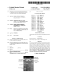
US 20080269589A1
(19) United States
(12) Patent Application Publication (10) Pub. No.: US 2008/0269589 A1
Thijs et al.
(43) Pub. Date:
(54) APPARATUS FOR THE DETECTION OF
(30)
Oct. 30, 2008
Foreign Application Priority Data
HEART ACTIVITY
Jul. 15, 2005
(75)
Inventors:
_
Aachen (DE); Robert B_ Elfring’
Aachen (DE); Jens Muehlsteff,
Aachen (DE); Olaf Such, Aachen
(51) Int CL
A61B 5/05
(DE)
(52)
PROPERTY
ELECTRONICS N. V., Eindhoven
(22)
App 1, No.1
PCT Filed;
(200601)
ABSTRACT
The invention relates to heart measurement and heart moni
KONINKLIJKE PHILIPS
(NL)
_
&
CLEVELAND, OH 44143 (US)
(73) Assignee:
_
US. Cl. ...................................................... .. 600/407
(57)
PHILIPS INTELLECTUAL
STANDARDS
595 MINER ROAD
_
Publication Classi?cation
Correspondence Address:
( 21 )
(EP) ................................ .. 051065449
Jeroen Adrianus Johannes Thijs,
toring, in particular the measurement of mechanical heart
activity, and includes a method and apparatus to using dop
pler radar to transmit an electromagnetic signal of a certain
frequency into, and detect a re?ected signal from out of, the
chest of the individual, to processing the detected signal to
produce an output signal representing the rate of change of the
doppler signal associated With the re?ected signal and to
11/995 , 543
1'd enti'fy fromt h e output s1gna
'
l a group 0 f at l east one 0 har
Jul, 14, 2006
acteristic point of the output signal, and further to calculate at
least one parameter representative of heart activity, this cal
PCT/[30652407
point. The apparatus provides a system for monitoring Which
Jan, 14, 2008
require repeated use of impedance cardiograms Which are
inappropriate for use by untrained personnel.
culation based on the at least one identi?ed characteristic
(86) PCT NO;
is particularly suitable for use in the home and Which does not
§ 371 (c)(1),
(2), (4) Date;
DR1 =
I
225
204
223
“V
q
’\/
/\_/
AU
DRZ
:
LP 100 Hz
Amplifier
HP 1 Hz
+5\/ >—|
GND
201
'53
-
>
x202
DC/DC
Doppler
Module
Patent Application Publication
Oct. 30, 2008 Sheet 1 0f 3
70
FIG. 1
US 2008/0269589 A1
Patent Application Publication
Oct. 30, 2008 Sheet 2 0f 3
Egon 2 82
How
Of’.
of
88 NIZ
New?
wow
mom
/
“J/Q
Ham
00Hm3NI
QzwA
US 2008/0269589 A1
Patent Application Publication
Oct. 30, 2008 Sheet 3 0f 3
US 2008/0269589 A1
‘I’.
‘I’.
T
T
0.
O.
T
T
m
\O.
\O.
m
|_I
l-?
m
IE
LO
LO
Ln
LO
0)
E
4-:
m
n!
m
N
m
Ln
Ln
I
|—|
N
LO
N
Ln
----0
_————>
————><
‘r.
N
m
‘r.
N
—|n——U
————m
-———-<:
c:
c:
N
LO
N
LO
Oct. 30, 2008
US 2008/0269589 A1
APPARATUS FOR THE DETECTION OF
HEART ACTIVITY
[0008]
The method includes transmitting an electromag
netic signal into the chest of an individual Which is then
re?ected back from any internal organs in its path. The elec
tromagnetic signal becomes doppler shifted in the event that
[0001]
The invention relates to a method to detect mechani
cal heart activity of an individual using doppler radar com
prising transmitting an electromagnetic signal of a certain
frequency into, and detecting a re?ected signal from out of,
the chest of the individual, and processing the detected signal
to produce an output signal representing the rate of change of
the doppler signal associated With the re?ected signal, the rate
of change With respect to time.
[0002] The use of frequency modulated doppler radar to
measure heart rate is knoWn. U.S. Pat. No. 4,958,638, for
example, describes a vital signs monitor utiliZing a frequency
modulated doppler radar beam Which When trained on the
surface of the chest from a distance provides a measurement
of heart rate. The frequencies of 3 and 10 GHZ used for the
vital signs monitor are reported as having minimal penetra
tion into the body.
[0003]
‘Less Contact: Heart-rate detection Without even
touching the user’ by Florian Michahelles, Ramon Wicki and
Bemt Schiele, Eighth International Symposium on Wearable
Computers, ISWC 2004, Volume: 1, pp. 4-7, 31 Oct.-3 Nov.,
2004, describes a system to measure heart-rate using micro
impulse radar pulses. The detected signal is ?ltered and the
distances betWeen all local maxima calculated and analyZed
for regularly occurring patterns . All maxima occurring Within
a certain distance are presumed to stem from the heart beat
and are used to derive the heart rate.
[0004] Us. Pat. No. 4,967,751 describes a system for mea
suring breathing rate using the transmission of a continuous
frequency electromagnetic Wave through the upper body of a
human being, the detection of the doppler shifted signal on
the other side of the upper body, the frequency modulation of
this detected signal and its retransmission back through the
upper body and eventual detection at the original transducer.
The signal contains cyclical information about the breathing
rate of the person. Further, the frequency modulation of the
doppler shifted signal alloWs the required signal to be identi
?ed With respect to any other stray signals detected by the
original transducer. These stray signals may originate from,
for example, back-scattering of the original signal by organs
in the body, for example the heart or lungs. U.S. Pat. No.
4,967,751 discloses that the movement of these organs intro
duces a doppler-frequency component into the back-scattered
signal and explains that this may originate from the breathing
rate, the beating rate of the heart and the movement of the
heart valves.
[0005] Us. Pat. No. 3,483,860 describes a method for
a re?ecting organ is moving relative to the transducer. This
doppler shifted signal is detected by the transducer and When
visually displayed shoWs a cyclical behavior representative of
heart activity. HoWever, if this signal is processed by a pro
cessor to produce the rate of change of the signal With respect
to time it is found that this outputted signal contains informa
tion Which alloWs information about mechanical heart activ
ity to be extracted from the further signal.
[0009] Speci?cally, the further signal contains cyclically
occurring features and surprisingly, When the further signal is
compared to a trace from an impedance cardiogram it can be
seen that equivalents of characteristic points found on the
trace of the impedance cardiogram can be identi?ed on the
further signal, alloWing parameters such as pre-ej ection
period and left ventricular ejection time, Which are normally
calculated using the impedance cardiogram, to be calculated
using the outputted signal. Therefore information represent
ing mechanical activity of the heart can be extracted from the
outputted signal and parameters can be calculated Which pro
vide a measure of mechanical heart activity. The method
requires no impedance cardiogram to be performed and yet
still alloWs the same parameters to be calculated. Equipment
to perform the method is easier to use, requiring simple place
ment of the transducer against the chest, and is therefore more
suitable for repeated measurement of heart activity and is
correspondingly more suited to repeated measurements, for
example in patient monitoring.
[0010]
The invention also relates to a system to detect
mechanical heart activity of an individual using doppler radar
comprising a transducer, to transmit electromagnetic signals
of a certain frequency into, and detect re?ected signals from
out of, the chest of the individual, a ?rst computer processor,
coupled to the transducer, to process the detected signal to
produce an output signal representing the rate of change of the
doppler signal associated With the re?ected signal, the rate of
change With respect to time, a second computer processor
arranged to identify from the output signal a group of at least
one characteristic point of the output signal, and a third com
puter processor arranged to calculate at least one parameter
representative of heart activity, the calculation based on the at
least one identi?ed characteristic point. This system has the
advantage that it alloWs the method of the invention to be
performed over multiple devices and thereby provide maxi
mum ?exibility in assessing the mechanical activity of the
heart of an individual. The computer processors can be situ
frequency signal into the body and detecting and processing
ated Within the same computer or be geographically separate
from each other. In the latter case, transmission of informa
tion betWeen the processors can be accomplished by any
knoWn Wireless means, or by modem connection, or by
the re?ected signal to produce an output signal. The output
knoWn computer network technology.
monitoring heart movement comprising transmitting a radio
signal is further differentiated to provide an indication of rate
of ejection of blood from the heart.
[0006] It is an object of the invention to provide an
improved measurement of mechanical heart activity.
[0007] This is achieved according to the invention Whereby
the method further comprises the steps of identifying from the
output signal a group of at least one characteristic point of the
output signal, and further calculating at least one parameter
representative of heart activity, the calculation based on the at
least one identi?ed characteristic point.
[0011]
The invention also relates to a Wearable apparatus to
detect mechanical heart activity of an individual using dop
pler radar, comprising a transducer to transmit electromag
netic signals of a certain frequency into the chest of the
individual, and to detect re?ected signals from out of the
chest, and to transmit a signal representative of the detected
signal to be received by a processing system, Which system is
arranged to use the received signal to calculate an output
signal representing the rate of change of the doppler signal
associated With the re?ected signal, the rate of change With
Oct. 30, 2008
US 2008/0269589 A1
respect to time, to identify from the output signal a group of at
least one characteristic point of the output signal, and to
calculate at least one parameter representative of heart activ
ity, the calculation based on the at least one identi?ed char
acteristic point.
[0012] This apparatus has the advantage that it can be Worn
by an individual While they move around and can therefore
acquire signals demonstrating mechanical heart activity
While the individual is ambulatory. It has the further advan
tage that the Wearable apparatus need only comprise a suit
able transducer for the production of electromagnetic signals
and need not comprise the processor, Which may itself be
remote from the Wearable apparatus, thereby saving space
and Weight in the Wearable apparatus. Thus the Wearable
apparatus has the advantage that it provides output signals to
a remote processor Which calculates the rate of change of the
originally detected signal With respect to time, identi?es the
characteristic points and calculates parameters. The remote
processor may be physically located in the same room as the
individual, or may even be located in another room in the
same house.
[0013]
The Wearable apparatus can be Worn by the indi
vidual on a strap or a harness or using other carrying means.
Because the electromagnetic signals can penetrate through
cloth and other Wearable materials the apparatus can also be
carried in a pocket constructed on the clothing of the indi
vidual and arranged to be situated in a position Where an
optimal signal is detected by the transducer.
[0014] The invention also relates to a processing system,
for receiving the signal transmitted from a Wearable apparatus
to detect mechanical heart activity of an individual using
doppler radar, the system arranged to receive a signal repre
sentative of a re?ected electromagnetic signal detected from
out of the chest of an individual, and further arranged to
calculate an output signal representing the rate of change of
the doppler signal associated With the re?ected signal, the rate
of change With respect to time, identify from the output signal
a group of at least one characteristic point of the output signal,
and calculate at least one parameter representative of heart
activity, the calculation based on the at least one identi?ed
to identify from the output signal a group of at least one
characteristic point of the output signal, and a third remote
computer processor arranged to calculate at least one param
eter representative of heart activity, the calculation based on
the at least one identi?ed characteristic point.
[0019] The system has the advantage that it alloWs the
ambulatory monitoring of mechanical heart activity using a
Wearable transducer Which emits electromagnetic signals and
detects doppler shifted re?ections of those signals, passes
those signals to a series of remote processors, and processes
those signals to produce a signal representative of mechanical
heart activity. The remote processors, for example, may be in
the same room as the individual and may even be in the same
computer, but could be in another room in the same building
or separated from each other geographically.
[0020] This system also has the further advantage that it can
be used to provide monitoring of mechanical heart activity
using a World Wide Web service. In this case, the individual
Who is monitored Wears the transducer in a housing, arranged
in some Way on his or her person, as above, so that a suitable
signal is detected Which has been re?ected from the heart, and
the processor Which calculates the rate of change of the
detected signal is contactable via the World Wide Web. In this
case the skilled person can arrange for the signal from the
Wearable apparatus to be transmitted to an intermediate pro
cessor, a computer With a connection to the World Wide Web,
say, Which is arranged to transmit the signal representative of
the detected signal through the World Wide Web to the remote
processor. Alternatively, the Wearable apparatus can be
equipped With suitable processing to alloW for the direct
transmission of the signal representative of the detected sig
nal into the World Wide Web to the remote processor.
[0021] Thus the system solves the problem of hoW to pro
vide monitoring of mechanical heart activity from a location
remote from the location of the individual being monitored.
[0022] The apparatus of the invention is particularly advan
tageously arranged When it emits continuous Wave electro
magnetic Waves, although as a feature this is not necessary.
characteristic point.
The apparatus of the invention achieves the desired result if
the emitted and re?ected signal is of such a duration that it is
able to encode information from at least a single heart beat.
[0015] This apparatus has the advantage that it processes
the signals from a portable apparatus arranged to detect dop
are emitted in the form of a continuous beam. HoWever,
pler radar signals from Within the chest of an individual and
processes them to produce signals representative of mechani
cal heart activity according to the method of the invention.
[0016] Thus the Wearable apparatus in combination With
This can de?nitely be achieved if the electromagnetic signals
pulsed electromagnetic signals can also be used if each single
pulse is long enough to encode the information from a single
heart beat, or, for example, if the time interval betWeen pulses
is very short in comparison With the time it takes the heart to
the remote processor together offer a solutions Which solves
beat once. In the later case, each pulse encodes some fraction
the problem of hoW to arrange for ambulatory monitoring of
mechanical heart activity of the individual.
of the information available in each heart beat about the heart
activity. In the case Where a train of very short pulses With a
very short time interval are used the information encoded in
[0017] The invention also relates to a system for the ambu
latory detection of mechanical heart activity of an individual
using doppler radar, comprising a transducer to transmit an
electromagnetic signal of a certain frequency, the transducer
positioned so that the doppler radar signal is emitted into the
the doppler shifted re?ected signals represents a sampling of
information from the heart.
[0023] The apparatus of the invention can be used With a
transducer arranged to produce electromagnetic signals of
chest of the individual, the transducer capable of detecting the
re?ected signal from out of the chest, and further arranged to
range produces re?ected signals from the heart. HoWever, the
transmit a signal representative of the detected signal, a ?rst
remote computer processor arranged to receive the signal
apparatus Works in a particularly advantageous manner When
the frequency is in a range of betWeen 800 MHZ and 4 GHZ.
representative of the detected signal, and arranged to:
[0018] process the detected signal to produce an output
signal representing the rate of change of the doppler signal
associated With the re?ected signal, the rate of change With
emits electromagnetic signals Which are of a single fre
quency, Within the limits of conventional operation of elec
tromagnetic antenna, as Will be appreciated by the person
respect to time, a second remote computer processor arranged
skilled in the art.
frequency in a range of betWeen 400 MHZ and 5 GHZ. This
[0024]
The apparatus is operated advantageously When it
Oct. 30, 2008
US 2008/0269589 A1
[0025] The invention is further elucidated and embodi
ments of the invention are explained using the following
[0033] A particularly advantageous embodiment utiliZes a
commercially available Microwave Motion Sensor KMY 24
?gures.
unit made by Micro Systems Engineering GmbH. It contains
[0026] FIG. 1 shoWs a typical trace from an ECG measure
ment of the heart.
a 2.45 GHZ oscillator and receiver in the same housing and
Works in continuous Wave mode. The dimensions of the beam
[0027] FIG. 2 shoWs a block diagram of the apparatus of the
invention.
[0028] FIG. 3 shoWs the output of the processor Which
antenna and in this case the unit contains an optimiZed patch
antenna With minimiZed dimensions and a Width of 3.5 cm,
processes the signal detected by the transducer.
[0029] As is commonly known, the heart is the organ Which
pumps blood around the body. It is subdivided into 4 cham
bers, consisting of 2 atria, Which receive blood entering the
heart, With deoxygenated blood returning from the body
entering into the right atrium and oxygenated blood from the
lungs entering into the left atrium, and 2 larger ventricles
Which are responsible for pumping blood out of the heart. The
right ventricle pumps deoxygenated blood received from the
right atrium out of the heart and to the lungs, Where it is
oxygenated. The left ventricle, the largest chamber in the
heart, is responsible for pumping oxygenated blood received
from the left atrium out into the rest of the body. As is also
are, amongst other things, dependent on the dimensions of the
producing a beam With a near ?eld radius of 2 cm. This
provides a Workable compromise betWeen too large an
antenna, Which Would produce a Wide beam easily contami
natable by re?ections from other structures, and too small an
antenna, Which Would produce a narroW beam Which is dif
?cult to position satisfactorily. In practice, a beam With a
Width in the range of 1 cm to 2.5 cm is advantageous because
it provides a Workable compromise betWeen the tWo extremes
described above. A beam With a Width in the range of 1.5 cm
to 3 cm is particularly advantageous for application of the
apparatus to large adults or adults With an enlarged heart. A
beam With a Width in the range of 0.5 cm to 1.75 cm is
advantageous for application of the apparatus to small chil
knoWn, measurements from electrocardiography, ECG, shoW
dren.
that the heart pumps in a cyclical fashion and ECG measure
ments alloW identi?cation of certain phases common to the
electrical sequence of the heart. FIG. 1 shoWs a typical output
trace from an ECG measurement. The characteristic spikes
shoWn in a typical trace are labeled P, Q, R, S and T, as
indicated. It is knoWn that the P spike, or Wave, is represen
[0034] The commercially available unit is utiliZed in the
folloWing Way. FIG. 2 shoWs a block diagram of the appara
tative of the depolarization, or excitation, of the atria. The
QRS spikes, knoWn commonly as the QRS-complex, are
representative of the excitation of the ventricles. The QRS
complex masks any signal from the repolarisation of the atria.
The T spike, or T Wave, is representative of the repolarisation
of the ventricles.
[0030]
Transducers for the detection of doppler shifted sig
tus. The doppler transducer 201 is poWered by a voltage
supply 202. The output of the doppler transducer 201 is pro
cessed through a high pass ?lter 203, a preampli?er 204 and
a loW pass ?lter 205. It Was found experimentally that the high
pass ?lter 203 should comprise a capacitance of 100 nF and a
resistor of 1 M9, as this enabled a faster decay of the signal
While removing the DC part of the signal from the doppler
module. The time constant "c of 0.1 s produces a cut-off
frequency of 1.59 HZ. Although the signal being detected is
re?ected from the heart Which beats With a frequency of the
order of 1 HZ, the attenuation of this ?rst order high pass ?lter
is loW enough not to destroy the signal. The gain of the
nals are commercially available, and are often used for the
purposes of detection of movement using the far ?eld of the
preampli?er 204 can be set in a range of 1 to 1000 but it Was
beam, for example in Radar measurements of tra?ic speed. It
found that a particularly advantageous gain Was 500. To
enable sampling, an 8th order loW pass ?lter Was realized With
is noW found, according to the invention that such transducers
can also be used for near ?eld measurements and are surpris
ingly suitable for detecting mechanical heart activity via the
detection of doppler shifted signals from the heart.
[0031] Generally in such doppler transducers, as is knoWn
in the art, an antenna emits an electromagnetic Wave Which,
a cutoff frequency of 100 HZ using operational ampli?ers.
[0035] FIG. 1 also shoWs tWo output signals, DR1 and
DR2, from the doppler transducer. As is knoWn in the art,
some commercially available transducers contain tWo mixer
diodes to provide additional information about the direction
of movement of the re?ecting object. HoWever, tWo signals
When it is re?ected from the surfaces of an object moving With
a component of velocity non-transverse to the impinging
electromagnetic Wave, produces a shift in the frequency of the
are not necessary for the apparatus to Work. If such a trans
electromagnetic Wave re?ected back to the antenna. This shift
from either mixer diode can be used for the calculation of rate
in frequency is called the doppler shift. This doppler shifted
of change.
re?ected Wave is detected by an antenna in the transducer,
Which may or may not be the same antenna as the emitting
[0036] It Was found that the Whole assembly is sensitive
enough to process signals that are re?ected by the heart.
antenna. The relative speed of movement of the re?ecting
object is encoded in the frequency shift of the detected
the transducer relative to the heart is important in detecting a
re?ected Wave and this value can be extracted using knoWn
useful signal. The electromagnetic signals must be re?ected
techniques.
from the heart itself in order for mechanical heart information
to be encoded in the re?ected signals. HoWever, it is found
[0032]
A transducer advantageously used in the apparatus
ducer is used to construct the apparatus the re?ected signal
[0037]
Experimental results shoW that the positioning of
of the invention contains a 2.45 GHZ oscillator operating in
continuous mode. It is knoWn that electromagnetic radiation
experimentally that individual variation betWeen subjects
is strongly absorbed in human tissue at around the frequen
cies of 2 to 10 GHZ, but it is found, according to this highly
advantageous embodiment of the invention, that the radiation
produced from an antenna operating at 2.45 GHZ, although
absorbed and scattered to some extent by layers of tissue,
produces a detectable signal.
respect of optimal signal detection for each individual. HoW
ever, if both the detected and output signals are visually
alters the correct position or positions of the transducer in
displayed on a display screen it is possible to see if the
transducer is correctly placed. If the transducer is placed in
such a Way that the heart is not in the emitted beam of signals,
or is not re?ecting the emitted signals back to the receiver,
Oct. 30, 2008
US 2008/0269589 A1
little or no cyclical activity Will be seen in the re?ected beam.
If the transducer is Well positioned a cyclical signal Will be
seen. A certain amount of experimentation is required in the
an impedance cardiagram, is more easily distinguishable
using the apparatus of the invention and the technical features
detailed in claim 1.
correct positioning of the transducer on the surface of the
chest of the individual before a suitable signal and therefore
the correct position identi?ed. It has been found that arrang
ing the sensor so that the emitted beam impinges on a plane
available ‘Niccomo’ hemodynamic monitor, supplied origi
structure predominantly parallel to the plane of the trans
ducer, for example a section of heart Wall muscle, is highly
nally by Medis GmbH, noW oWned by CardioDynamics, Sec
tion D, ‘Description of the calculated parameters’, pages
[0051] Using these characteristic points several parameters
can be calculated, as is commonly knoWn in the art, but see for
example user manual for the pc-softWare of the publically
advantageous in receiving an adequate re?ected signal.
55-64, detailing commonly knoWn clinically relevant param
[0038] The transducer can be incorporated in a suitable
housing Which is advantageously dimensioned so that it can
eters and details of their calculation using the knoWn charac
be arranged ?at against the chest, for example the sternum of
teristic points. These parameters include pre-ej ection period,
left ventricular ejection time, systolic time ratio and ejection
the individual. Suitable dimensions are betWeen 3 and 6 cm
time ratio. The parameter of left ventricular ejection time is
Wide and betWeen 4 and 7 cm long. These siZes alloW for the
sometimes referred to in the art as left ventricular ejection
hardWare to be contained in the housing While maintaining
phase. The calculation of these parameters proceeds along the
the housing at a siZe Which can be used effectively on an
same lines as for their calculation using the prior art method
individual.
of impedance cardiography and is therefore not the subject of
[0039] The technical steps to be performed in the process
ing of the recorded data to provide an output signal containing
this invention. HoWever, as can be seen from the Niccomo
the rate of change of the data With respect to time can be
undertaken by a person skilled in the art using knoWn data
processing techniques. For example, it can be achieved using
the Matlab computer language.
[0040] Similarly, the method used to extract a signal repre
sentative of the rate of change of the signal With respect to
time Will be knoWn to the person skilled in the art. For
example, the signal can be sampled and the rate of change of
each sample over the length of the sample extracted. HoW
ever, the output signal can also be calculated by inverse trans
forming the detected signal to derive the mathematical func
tion of the signal and mathematically deriving the function to
produce the ?rst order derivative.
[0041] FIG. 3 shoWs the output of the processor Which
processes the signal detected by the transducer. The ?rst trace
user manual, calculation of these parameters in the prior art
requires characteristic points derived from an impedance car
diogram. The invention provides a measure of mechanical
heart activity Which provides improved information concem
ing heart movement.
[0052] The computer processing arranged to calculate the
doppler signal, calculate the rate of change of the doppler
signal, identify the characteristic points and then calculate the
parameters from the characteristic points can be situated in
various items of equipment. Although the transducer itself
Will of necessity be positioned, When in use, in such a Way that
a doppler signal is produced Which encodes information
about the heart, the processing that occurs after the transducer
has received the initial signal need not be physically coupled
to the transducer but may be arranged to received the output of
the transducer Wirelessly using any knoWn Wireless means.
301 is the detected signal. The second trace 302 is the rate of
Similarly, the stages of processing may be separated and
change of the detected signal With respect to time. The third
on the trace representing the rate of change of the detected
undertaken in processing units Which are situated physically
apart from each other but arranged to relay or transmit their
results to each other using any knoWn method including, for
example, Wireless transmission, transmission doWn a tele
phone line or, say, along a ?xed, physical connection such as
signal. Speci?cally these characteristic points, knoWn to the
a Wire.
skilled person, are:
[0053] As an example of hoW the invention may be Worked,
the individual Whose heart activity is to be measured is pro
trace 303 is an example of a trace from an impedance cardio
gram. It can be seen from FIG. 3 that the characteristic points
of the impedance cardiogram 303 can be similarly identi?ed
[0042]
[0043]
A: representing the contraction of the atrium
B: representing the opening of the aortic valve and
the beginning of the systolic ejection phase
[0044] C: representing maximum systolic How
[0045] X: representing the closing of the aortic valve and
the end of the ejection phase
[0046] Y: representing the closing of the pulmonal valve
[0047] 0: representing the opening of the mitral valve
[0048] In other Words, points equivalent to knoWn charac
teristic points identi?able from an impedance trace are noW
also identi?able from a signal Which is the rate of change of a
detected doppler signal re?ected from the heart of an indi
vidual.
[0049] The characteristic points can be identi?ed using
knoWn techniques of signal processing and is a matter of
design for the person skilled in the art. For example, the
characteristic points can be identi?ed from analysis of the
morphology of the rate of change trace 302.
[0050] It Was further found experimentally that character
istic pointA, Which is normally not very clearly identi?able in
vided With a Wearable doppler transducer ?tted into a com
fortable harness and coupled to a transmitter arranged to
transmit the detected signal to a ?rst remote processor Which
performs the actions of processing the signal to produce a
doppler signal, calculating the rate of change of this doppler
signal, identifying the characteristic points and using these to
calculate any required parameters. In the case When the
resulting ?rst processor is in the same location as the indi
vidual, for example their home, residence or hospital Ward,
this ?rst processor can be arranged to further transmit the
resulting parameters, along With the doppler trace and/or a
trace of the rate of change of the doppler signal as appropriate,
to a remote second processor situated in a computer Worksta
tion. The results can be accessed at this Workstation by a
doctor or other medical professional for the purposes of
monitoring the health of the individual.
[0054] Alternatively, the ?rst processor could be arranged
to calculate only the doppler signal and communicate this to
the second processor Which can itself be arranged to perform
all further analysis.
Oct. 30, 2008
US 2008/0269589 A1
[0055] Alternatively, the ?rst processor could be arranged
to calculate only the doppler signal and calculate the rate of
change of this doppler signal and then communicate this to
the second processor Which can itself be arranged to perform
all further analysis. In this sense the step of processing the
detected signal to produce an output signal representing the
rate of change of the doppler signal associated With the
re?ected signal, can as an example be performed by ?rst
processing the detected signal to produce a doppler signal and
then processing the doppler signal to produce an output signal
representing the rate of change of the doppler signal With
also be transmitted directly to a processor Which is part of a
computer aided detection system designed to automatically
monitor the individual’s health and alert him or a doctor or a
health monitoring service in the event that the calculated
parameters indicate a deterioration in the individual’s condi
tion.
[0062] It can be seen in the light of the information above
that the invention provides a system for monitoring Which is
particularly suitable for use in the home and Which does not
require repeated use of impedance cardiograms Which are
inappropriate for use by untrained personnel.
respect to time. In fact calculation of the doppler signal itself
is not strictly necessary as an intermediate step and other
methods of calculating this rate of change of the doppler
signal may be performed by the person skilled in the art as a
matter of design, once he understands that it is the rate of
1. A method to detect mechanical heart activity of an indi
vidual using doppler radar comprising:
transmitting an electromagnetic signal of a certain fre
quency into, and detecting a re?ected signal from out of,
the chest of the individual,
change of the doppler signal information Which alloWs iden
ti?cation of the characteristic points.
[0056] Alternatively, the ?rst processor could be arranged
to calculate the rate of change of the doppler signal and
identify the characteristic points and then communicate these
to the second processor Which is arranged to perform the
processing, by processing system the detected signal to
produce an output signal representing the rate of change
of the doppler signal associated With the re?ected signal,
further analysis.
[0057] Alternatively, the ?rst processor could be arranged
the rate of change With respect to time, Wherein the
method further comprises the steps of:
to calculate the rate of change of the doppler signal, identify
the characteristic points and then calculate the parameters,
communicating any combination of these to a further proces
sor or Workstation Where the results can be examined by a
doctor or other medical professional.
[0058] In an alternative embodiment to the Wireless transfer
of information betWeen the transducer and processor, the
transducer may store the information contained in the
detected signal for transfer to a processor via a docking sta
tion or other ?xed connection after the measurement session
is complete. This removes the need for Wireless capability and
thereby reduces the possibility of signal interference in an
environment With a inherently large electromagnetic signal
transmitting a signal representative of the detected signal to
a processing system,
identifying, by the processing system from the output sig
nal a group of at least one characteristic point of the
output signal,
and further calculating, by the processing system at least
one parameter representative of heart activity, the calcu
lation based on the at least one identi?ed characteristic
point,
Wherein the signal representative of the detected signal is
transmitted Wirelessly to a computer With a connection
to the World Wide Web and from said computer through
the World Wide Web to the processing system.
2. (canceled)
3. A Wearable apparatus to detect mechanical heart activity
of an individual using doppler radar, comprising:
load.
Alternatively, the transducer may remain connected
a transducer to transmit electromagnetic signals of a cer
to the processor via a ?xed connection, such as a lead, during
tain frequency into the chest of the individual, and to
detect re?ected signals from out of the chest,
and to transmit a signal representative of the detected sig
nal to a processing system, Which system is arranged to
use the received signal to calculate an output signal
[0059]
the measurement session. This also reduces the possibility of
interference While alloWing interim results to be calculated
during the measurement session. This provides advantages in
the case Whereby the individual experiences a sudden
increase in symptoms and it becomes desirable to communi
cate information regarding the mechanical activity of the
heart urgently to a medical professional.
[0060] In an exemplary embodiment, the transducer, situ
ated in a comfortable harness is used by the individual once a
day for a short period of time, say 5 mins, to take readings of
the activity of the heart. The resultant data, either as raW data
or as identi?ed characteristic points or as calculated param
eters is transmitted to a geographically remote location Where
it is analyZed by a doctor or other medical professional for
monitoring of the individual over time.
[0061] In this case the correct position of the transducer on
the chest of the individual can be initially identi?ed using an
initially performed impedance cardiogram. Thereafter, the
individual simply places the transducer in the correctly iden
ti?ed position at regular intervals, say once a day, and oper
ates it himself to provide parameters Which provide informa
tion concerning the mechanical activity of his heart. The
resulting information is advantageously used When commu
nicated to a doctor or health monitoring service, but could
representing the rate of change of the doppler signal
associated With the re?ected signal, the rate of change
With respect to time,
identify from the output signal a group of at least one
characteristic point of the output signal,
and calculate at least one parameter representative of heart
activity, the calculation based on the at least one identi
?ed characteristic point,
Wherein the apparatus comprises means for transmitting
the signal representative of the detected signal Wire
lessly to a computer With a connection to the World Wide
Web, Wherein said computer is adapted to further trans
mit the signal representative of the detected signal
through the World Wide Web to the processing system.
4. A processing system, for receiving a signal transmitted
from a Wearable apparatus to detect mechanical heart activity
of an individual using doppler radar, the system arranged to
receive a signal representative of a re?ected electromagnetic
signal detected from out of the chest of an individual, and
further arranged to:
Oct. 30, 2008
US 2008/0269589 A1
calculate an output signal representing the rate of change of
the doppler signal associated With the re?ected signal,
the rate of change With respect to time,
identify from the output signal a group of at least one
characteristic point of the output signal,
9. The apparatus as claimed in claim 8, Wherein the trans
ducer emits continuous Wave electromagnetic signals at a
frequency in a range betWeen 800 MHZ and 4 GHZ.
10. The apparatus as claimed in claim 9, Wherein the trans
ducer emits continuous Wave electromagnetic signals at a
and calculate at least one parameter representative of heart
activity, the calculation based on the at least one identi
frequency of 2.45 GHZ.
?ed characteristic point,
Wherein the processing system is adapted to receive the
comprises a display screen for the display of the output signal.
signal representative of the detected signal through the
World Wide Web from a computer With a connection to
the World Wide Web, Wherein said computer is adapted to
receive the signal representative of the detected signal
Wirelessly from the Wearable apparatus.
5. (canceled)
6. The apparatus as claimed in claim 3, Wherein the rate of
change of the detected signal With respect to time is calculated
as the ?rst order derivative of the detected signal With respect
to time.
7. The apparatus as claimed in claim 3, Wherein the trans
ducer is arranged to emit continuous Wave electromagnetic
signals.
8. The apparatus as claimed in claim 3, Wherein the trans
ducer emits continuous Wave electromagnetic signals at a
frequency in a range betWeen 400 MHZ and 5 GHZ.
11. The apparatus as claimed in claim 3, Wherein it further
12. The apparatus as claimed in claim 3, Wherein the
parameters representative of heart activity include at least one
of pre-ejection period, left ventricular ejection time, systolic
time ratio and ejection time ratio.
13. The apparatus as claimed in claim 3, Wherein it is
further arranged to output the value of at least one calculated
parameter representative of heart activity.
13. The method of claim 1, Wherein the at least one param
eter representative of heart activity is transmitted to a com
puter aided detection system designed to automatically moni
tor the individual ’s health and output and alert in the event that
the parameter indicates a deterioration in the individual’s
condition.