1
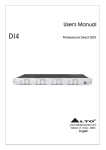
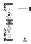
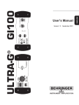
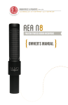
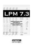
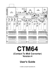
User's Manual
DI1
DIRECT BOX
www.altoproaudio.com
Version 2.4 September 2005
English
result in damage to the product and
possibly the user.
Unplug the product before electrical storms
occur and when unused for long periods of
time to reduce the risk of electric shock or
fire.
SAFETY RELATED SYMBOLS
CAUTION
RISK OF ELECTRIC SHOCK
DO NOT OPEN
This symbol, wherever used, alerts
you to the presence of un-insulated
and dangerous voltages within the
product enclosure. These are voltages
that may be sufficient to constitute the
risk of electric shock or death.
External Connection
Always use proper ready-made insulated
mains cabling (power cord). Failure to do
so could result in shock/death or fire. If
in doubt, seek advice, from a registered
electrician.
This symbol, wherever used, alerts
you to important operating and maintenance instructions. Please read.
Protective Ground Terminal
AC mains (Alternating Current)
Hazardous Live Terminal
Do not Remove any Covers
Within the product are areas where high
voltages may present. To reduce the risk
of electric shock do not remove any
covers unless the AC mains power cord
is removed.
Covers should be removed by qualified
service personnel only.
No user serviceable parts inside.
ON: Denotes the product is turned on.
OFF: Denotes the product is turned off.
WARNING
Describes precautions that should be
observed to prevent the possibility of
death or injury to the user.
Fuse
To prevent fire and damage to the
product, use only the recommended
fuse type as indicated in this manual.
Do not short-circuit the fuse holder.
Before replacing the fuse, make sure
that the product is OFF and disconnected
from the AC outlet.
CAUTION
Describes precautions that should be
observed to prevent damage to the
product.
Disposing of this product should
not be placed in municipal waste
and should be separate collection.
Protective Ground
Before turning the product ON, make sure
that it is connected to Ground. This is to
prevent the risk of electric shock.
Never cut internal or external Ground wires.
Likewise, never remove Ground wiring
from the Protective Ground Terminal.
WARNING
Power Supply
Ensure that the mains source voltage
(AC outlet) matches the voltage rating
of the product. Failure to do so could
1
Operating Conditions
Servicing
Always install in accordance with the
manufacturer's instructions.
To avoid the risk of electric shock and
damage, do not subject this product to
any liquid/rain or moisture. Do not use this
product when in close proximity to water.
Refer all servicing to qualified service
personnel only.
Do not perform any servicing other than
those instructions contained within the
User's Manual.
Do not install this product near any direct
heat source.
Do not block areas of ventilation. Failure
to do so could result in fire.
Keep product away from naked flames.
IMPORTANT SAFETY INSTRUCTIONS
Read these instructions
Follow all instructions
Keep these instructions. Do not discard.
Heed all warnings.
Only use attachments/accessories
specified by the manufacturer.
Power Cord and Plug
Do not tamper with the power cord or plug.
These are designed for your safety.
Do not remove Ground connections!
If the plug does not fit your AC outlet seek
advice from a qualified electrician.
Protect the power cord and plug from any
physical stress to avoid risk of electric shock.
Do not place heavy objects on the power
cord. This could cause electric shock or fire.
Cleaning
When required, either blow off dust from
the product or use a dry cloth.
Do not use any solvents such as Benzol
or Alcohol.
For safety, keep product clean and free
from dust.
2
Preface
Dear Customer:
Thanks for choosing LTO DI1 Direct Box and thanks for choosing one of the results of
LTO AUDIO TEAM job and researches.
For our LTO AUDIO TEAM, music and sound are more than a job...are first of all passion
and let us say...our obsession!
We have been designing professional audio products for a long time in cooperation with some
of the major brands in the world in the audio field.
The LTO line presents unparalleled analogue and digital products made by Musicians for
Musicians in our R&D centers in Italy, Netherlands, United Kingdom and Taiwan. The core
of our digital audio products is a sophisticated DSP (Digital Sound Processor) and a large
range of state of the art algorithms which have been developed by our Software Team
for the last 7 years.
Because we are convinced you are the most important member of LTO AUDIO TEAM
and the one confirming the quality of our job, we would like to share with you our work
and our dreams, pay attention to your suggestions and your comments.
Following this idea we create our products and we will create the new ones! From our side,
we guarantee you and we will guarantee you also in future the best quality, and the best fruits
of our continuous researches and the best prices.
The DI1 Direct Box has several basic functions: converting a high impedance signal to a
low impedance signal; converting a "hot" instrument or line level (and sometimes even
speaker level signal) signal to a microphone level signal suitable for connection to the Mic
Input of a mixing console etc. And it used to prevents hum and noise pick up due to special
transformer decoupling.
Nothing else to add, but that we would like to thank all the people that made the LTO
DI1 Direct Box a reality available to our customers, thank our designers and all the LTO
staff, there to make possible the realization of products containing our idea of music and
sound and there to support you, our customers, in the best way, conscious that you are
our best richness.
Thank you very much.
LTO AUDIO TEAM
3
TABLE OF CONTENT
1. INTRODUCTION ........................................................................................5
2. YOUR DI 1 FEATURES..............................................................................5
3. CONTROL ELEMENTS .............................................................................5
3.1 The Front Panel
3.2 The Rear Panel
4. APPLICATIONS...........................................................................................7
4.1 When the input signal is a Bass Guitar
4.2 When the input signal is a microphone
4.3 How to convert a strong signal into MIC level signal
4.4 How to isolate the instrument on stage from the mixing console
5. TECHNICAL SPECIFICATIONS .............................................................9
5.1 Specifications
5.2 Block Diagram
6. WARRANTY ...............................................................................................11
4
1. INTRODUCTION
DI stands for " Direct Injection" and DI Boxes are also called Direct Boxes. You need to
use Direct Boxes if you wish to convert a high impedance instrument signal or an unbalanced signal into a format that will be suitable for direct connection into a mixer.
With the
LTO DI 1 Direct Box,
a. You can convert a high impedance signal into a low impedance signal.
b. You can convert an unbalanced signal into a balanced signal.
c. You can convert a line level signal into a microphone level signal for connection into the
Microphone input of the mixer.
d. You can isolate the instrument on stage from the mixer. In such way you can eliminate
noise caused by the ground loop.
There are basically two different kind of Direct Boxes on the market: Passive and active.
Both will be connected to the MIC input of the Mixer but active boxes such as your DI 1
perform better and produce better frequency response.
2. YOUR DI 1 FEATURES:
XLR input and output connectors
Converts unbalanced input into balanced output
Phase problems instantly corrected through PHASE INVERSION switch
Ground loop problems eliminated via GND LIFT switch
8kHz High cut Filter available for guitar applications
1 CHANNEL Direct Box for applications in recording studio and stage
Special transformer decoupling in order to avoid hum and noise pick-up
Outstanding audio performances insured by ultra-low noise operational amplifiers
3. CONTROL ELEMENTS
3.1 The Front Panel
(2)
R
LTO
20dB
20dB
DI1
DIRECT BOX
PHASE
INPUT ATTEN.
(3)
GND LIFT
HIGH CUT(8kHz)
(4)
(5)
5
ON
Battery PWR
OUTPUT
(6)
(1)
1. Battery Power Switch
This push-button will activate the power supplied by the internal 9 Volt Battery (not
supplied). The (2) Led will blink at several seconds intervals. If you are using your
DI 1 with external phantom power you can release the switch in order to preserve
the battery life.
2. Power LED
When operating with phantom power this LED will light up continuously. If you are using
the internal 9 Volt battery, the LED will blink at several seconds intervals.
3. 20dB Attenuation Switches on input
Press either of these switches and you will attenuate the input signal by 20dB. In
such way you can produce increased headroom and reduce the risk of distortion
because of level peaks at input level when the input signal is quite hot.
4. Phase Inversion Switch
By pressing this switch you will reverse the signal phase by 180 . In normal situations,
just forget about this switch but in case of inversion of the connectors this switch becomes very useful to compensate the phase cancellation
5. GND Lift Switch
This switch disconnects the input signal ground from the output signal ground. In
this way you can avoid hum produced by ground loop.
6. High frequency Filter at 8 kHz
You can press this switch and activate the 8 kHz High Cut Filter when using an electric guitar with your DI 1 Direct Box.
3.2. The Rear Panel
(9)
9V BATTERY
LINK
TIP/PIN 2
SLEEVE/PIN 1/3
NEW TIDE
1
3
2
INPUT
INPUT
OUTPUT
(7)
(10)
(8)
7. The Battery compartment
You can insert or change the 9 Volt Battery by loosen the screw and open the
compartment.
6
8. Input Connectors
Both XLR and unbalanced 1/4" TRS jack input connectors are supplied in your DI 1
Direct Box for maximum flexibility
9. Link Connector
This 1/4" TRS jack will output the incoming signal directly being wired in parallel
with the Input Connectors.
10. Output Connector
Finally, the output signal at MIC level will be produced by this XLR output connector.
You must pay particular attention to the wiring of this XLR connector if phantom power
of +48V is supplied to your DI 1 box.
Phantom
Power Supply
XLR Connector
PIN1 ( Ground )
GND
+48V
+48V
PIN2
PIN3
4. APPLICATIONS
So, we are telling you that after you have spent a fortune for your gear, you still need
to by an extra piece of equipment such as the DI 1 box? You will be amazed how
the DI 1 will transform your audio system whatever for studio or for live applications:
No risk of miss-match impedance, no ground loop and hum.
Please look at the following examples of applications
4.1 When the input signal is a Bass Guitar
You can connect your bass guitar directly into your DI 1. Then you can connect
the DI 1 into the MIC input of your mixer. In such a way you do not need a Bass
Amplifier on stage but you can still feed a Bass Amp using the Link Output connector of your DI 1.
From a bass guitar
For monitoring
To Microphone Input of a mixing console
Input
LTO
20dB
Output
Link
R
20dB
INPUT ATTEN.
DI1
DIRECT BOX
PHASE
GND LIFT
OUTPUT
7
HIGH CUT(8kHz)
ON
Battery PWR
4.2 When the input signal is a microphone
In this way the unbalanced output of a microphone is converted into a balanced one.
In such way you can cover a longer distance from the microphone to the mixer still
avoiding noise problems.
From a Microphone
To a Microphone Input of a mixing console
Input
R
LTO
20dB
20dB
Output
DI1
DIRECT BOX
PHASE
INPUT ATTEN.
GND LIFT
HIGH CUT(8kHz)
ON
Battery PWR
OUTPUT
4.3 How to convert a strong signal into MIC level signal
If you connect a line level signal or a speaker signal into a MIC input you would create
a disaster. To avoid this just use either or both the 20dB Attenuation Switches on your
DI 1.
From a Strong Instrument
To a Microphone Input of a mixing console
Input
R
LTO
20dB
20dB
INPUT ATTEN.
Output
DI1
DIRECT BOX
PHASE
GND LIFT
OUTPUT
HIGH CUT(8kHz)
ON
Battery PWR
4.4 How to isolate the instrument on stage from the mixing console
Tricky stuffs now from your DI 1 box. OK in order to avoid ground problem the ground
connection of an instrument to the mixer should be made with the DI 1. But in some
case the instrument will be connected to an amplifier as well through the same DI 1,
so you have now a grounding point with the amplifier and another one with the mixer.
If small differences occur in the ground of the amplifier and the mixer, AC current will
flow into the shield. The resulting "ground loop" and 50/60 Hz noise will radiate from the
shield to the center conductor and will produce hum.
Fortunately your DI 1 is equipped with a GND Lift Switch that will eliminate the interference cause by the ground loop.
8
5. TECHNICAL SPECIFICATIONS
5.1 Specifications
Inputs
Inputs
Input Impedance
Maximum Input Level
1/4" jack unbal. In/ Link Out
XLR unbalanced In
max 250kOhm
+2/+22/+42 dBm
Outputs
Outputs
XLR balanced Out
Load Impedance
>600Ohm
Maximum Output Level +6dBm
System specifications
Bandwidth (100kOhm)
Bandwidth (600Ohm)
Bandwidth (High Cut)
Noise Level
THD+N @ 1 KHz/1dBm
10Hz to 200kHz( 3dBm)
10Hz to 45kHz( 3dBm)
10Hz to 8kHz( 3dBm)
-105dBm
<0.01%
Phantom power
Battery
18V DC to 48V DC
9V block cell 6LR91
Dimensions
Weight
128(W)
0.8Kg
Power supply
Physical
9
123.5(D)
44.2(H)mm
10
A
B
C
D
LINK
5e
3c
4d
2b
1a
CN3
CN-JY6351G-02
5e
3c
4d
2b
1a
CN2
XLMN-3PH
4
2
3
1
1
CN4
CN-JY6351G-02
INPUT
INPUT
1
BATTERY +9V
SW2
-20dBATTENUATION
2
SW6
BATTERY POWER
SW3
-20dBATTENUATION
2
LED1
LED CONTROL
SW1
8KHz HIGH CUT
3
IC1
T1
PHANTOMPOWER
STEP-DOWNCONVERTER
3
SW5
GND LIFT
SW4
PHASE
4
4
2
3
1
OUTPUT
A
B
C
D
5.2 Block Diagram
6. WARRANTY
1. WARRANTY REGISTRATION CARD
To obtain Warranty Service, the buyer should first fill out and return the enclosed Warranty
Registration Card within 10 days of the Purchase Date.
All the information presented in this Warranty Registration Card gives the manufacturer a
better understanding of the sales status, so as to purport a more effective and efficient
after-sales warranty service.
Please fill out all the information carefully and genuinely, miswriting or absence of this
card will void any of your warranty service.
2. RETURN NOTICE
2.1 In case of return for any warranty service, please make sure that the product is well
packed in its original shipping carton, and it can protect your unit from any other extra
damage.
2.2 Please provide a copy of your sales receipt or other proof of purchase with the returned
machine, and give detail information about your return address and contact telephone
number.
2.3 A brief description of the defect will be appreciated.
2.4 Please prepay all the costs involved in the return shipping, handling and insurance.
3. TERMS AND CONDITIONS
3.1
LTO warrants that this product will be free from any defects in materials and/or
workman-ship for a period of 1 year from the purchase date if you have completed the
Warranty Registration Card in time.
3.2 The warranty service is only available to the original consumer, who purchased this
product directly from the retail dealer, and it can not be transferred.
3.3 During the warranty service, LTO may repair or replace this product at its own
option at no charge to you for parts or for labor in accordance with the right side of
this limited warranty.
3.4 This warranty does not apply to the damages to this product that occurred as the
following conditions:
Instead of operating in accordance with the user's manual thoroughly, any abuse or
misuse of this product.
Normal tear and wear
The product has been altered or modified in any way .
Damage which may have been caused either directly or indirectly by another product/
force/etc.
Abnormal service or repairing by anyone other than the qualified personnel or technician.
And in such cases, all the expenses will be charged to the buyer.
11
3.5 In no event shall LTO be liable for any incidental or consequential damages. Some
states do not allow the exclusion or limitation of incidental or consequential damages,
so the above exclusion or limitation may not apply to you.
3.6 This warranty gives you the specific rights, and these rights are compatible with the state
laws, you may also have other statutory rights that may vary from state to state.
12
SEIKAKU TECHNICAL GROUP LIMITED
No. 1, Lane 17, Sec. 2, Han Shi West Road, Taichung 40151 Taiwan
http://www.altoproaudio.com Tel: 886-4-22313737
email: [email protected] Fax: 886-4-22346757
All rights reserved to ALTO. All features and content might be changed
without prior notice. Any photocopy, translation, or reproduction of part of this
manual without written permission is forbidden. Copyright c 2005 SEIKAKU GROUP
NF00968-2.4