1
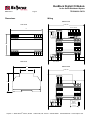
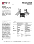
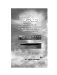
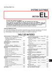
BusBlock Digital I/O Module
for the Smart Distributed System
BBK-4040-5
TECHNICAL DATA
0104
Description
The Holjeron BusBlock I/O Module is designed to handle small amounts of I/O in
a limited amount of space. The BusBlock
I/O Module comes in two versions: twelve
inputs/eight outputs and eight inputs/six
relay outputs. All I/O is optically isolated
from the bus.
Field terminations are captive screw terminals. Each input and output has its own
LED indication for immediate verification
of I/O states.
Specifications
Warranty/Remedy
Part Numbers
Seller warrants its products to be free
from defects in design, material and
workmanship under normal use and
service. Seller will repair or replace
without charge any such products it
finds to be so defective on its return to
Seller within 18 months after date of
shipment by Seller. The foregoing is
in lieu of all other expressed or implied warranties (except title), including those of merchantability
and fitness for a particular purpose. The foregoing is also purchaser’s sole remedy and is in lieu of
all other guarantees, obligations, or liabilities or any consequences incidental, or punitive damages attributable to
negligence or strict liability, all by way
of example.
Electrical
While Holjeron provides application
assistance, personally and through
our literature, it is up to the customer
to determine the suitability of the
product in the application.
All information contained herein, including illustrations, specifications and
dimensions, is believed to be reliable
as of the date of publication, but is
subject to change without notice.
Inputs
Outputs -DIG128
-DIG086
Environmental
Physical
12 Input / 8 Output
8 Input / 6 Relays
SDS Voltage Range
Current Consumption
Data Rates
Type
Number
BBK-DIG128
BBK-DIG086
Voltage Range
Maximum Current
Isolation
Type
Number
Voltage Range
Maximum Current
Isolation
Type
Number
Voltage Range
Maximum Current
Isolation
Temperature
Storage
Operating
Humidity
Vibration
Shock
Dimensions
Weight
Color
Case Material
Mounting
Terminations
Indication
Power
Error
SDS
I/O
BBK-DIG128
BBK-DIG086
11-25 VDC
60 mA
125, 250, 500 and 1000 kbps
Current Sinking (Sourcing load)
Twelve (12)
Eight (8)
10-28 VDC
20 mA per input
1500 Vrms
Current Sinking
Eight (8)
10-28 VDC
200 mA
1500 Vrms
Relay
Six (6)
10-125 VDC, 24-240 VAC
2 Amps @ 115 VAC
1500 Vrms
-30° to 70° C (-22° to 158° F)
0° to 60° C (32° to 140° F)
5-95% RH, non-condensing
2G at 10 to 500 Hz
10G
5.50" H x 3.48" W x 1.00" D
12 oz
Bone Gray
Polycarbonate
DIN Rail or foot mount
Captive Screw Terminal
Green
Red
Green
Green
th
Holjeron • 25599 SW 95 Avenue, Suite E • Wilsonville, OR 97070 • 503.582.0820 • Fax 503.582.9166 • www.holjeron.com
BusBlock Digital I/O Module
for the Smart Distributed System
BBK-4040-5
TECHNICAL DATA
Page 2
Dimensions
Wiring
BBK-DIG128
TOP VIEW
10-30 VDC
Power
Act. Error
0
1
2
3
4
5
6
3.47"
10
Out2
Out3
LOAD
LOAD
Out0
Out1
LOAD
LOAD
Out7
LOAD
Out6
5
6
7
Out0 Out1 Out2 Out3
Out4 Out5 Out6 Out7
In4
In5
In6
In7
COM COM COM COM
In0
In1
In2
In3
COM COM COM COM
1
2
3
4
5
6
7
8
1
9 0
1
1
4
5
7
11
In3
9
4
In10 In11
In2
8
2 3
In9
In1
7
1
In8
In0
6
In7
5
In6
4
In5
3
In4
2
0
DC+ DC- Bus+ Bus-
0
1
LOAD
Out4
7
Er
ror
0
LOAD
LOAD
Bus-
DC-
Bus+
In11
DC+
In9
In10
In8
SDS CONNECTOR
Out5
OUTPUT WIRING
5.50
INPUT WIRING
END VIEW
3.53
BBK-DIG086
1.77"
10-30 VDC
Bus-
DC-
Bus+
DC+
SDS CONNECTOR
2.27"
Er
ror
2 3
6
DC+ DC- Bus+ Bus-
V-
V-
V+
V+
In5
In6
In7
In0
In1
In2
In3
In3
In2
In1
INPUT WIRING
Out4 Out5
Out0 Out1 Out2 Out3
1
2
3
4
5
6
7
8
1
9 0
1
1
OUTPUT
WIRING
(Typical of 6)
LOAD
In4
In0
In7
In6
In5
1
COM COM COM COM
0
In4
0
10-125 VDC
24-240 VAC
th
Holjeron • 25599 SW 95 Avenue, Suite E • Wilsonville, OR 97070 • 503.582.0820 • Fax503.582.9166 • www.holjeron.com
BusBlock Digital I/O Module
for the Smart Distributed System
TECHNICAL DATA
BBK-4040-5
Page 3
Configuration
Quick Start
Operation
A BusBlock module can be configured using several tools. The information below
summarizes the configuration tools available and hardware requirements for each
tool.
The following steps are the minimum
steps to configure BusBlock module.
Default values are shown in bold typeface.
BusBlock modules are simple digital input/output devices. Each input and output
is available to the host controller. There
are minimal configuration options to affect
the behavior of the BusBlock Module, as
described on the following pages.
Holjeron Device Manager for SDS
Set Device Address
Requires an HSIM Portable (RS-232 to
CAN converter) that connects to the serial
port of a personal computer. The bus or
the HSIM Portable must have power.
Using one of the tools described above,
change the device address from the default. All units are shipped from the factory as address 126.
Honeywell hand-held activator
The Honeywell activator may not supply
enough power by itself. The SDS bus
might require external power to be applied.
Note
Set the address before attaching any
component to a complete bus. This
will help prevent duplicate addresses
on a bus.
Note
When using a packaged control system, such as Think & Do Software, it is
not necessary to explicitly read input
and output variables. The SDS I/O
Driver and Interface Card perform this
function. All that is required is to map
inputs and outputs as described in the
software user manual.
Think & Do Software
Requires a Honeywell PC Interface Card
with separate bus power. Follow the instructions for installing the SDS Driver in
I/O View.
th
Holjeron • 25599 SW 95 Avenue, Suite E • Wilsonville, OR 97070 • 503.582.0820 • Fax 503.582.9166 • www.holjeron.com
BusBlock Digital I/O Module
for the Smart Distributed System
BBK-4040-5
Inputs
Bit
0
1
2
3
4
5
6
7
8
9
10
11
TECHNICAL DATA
Page 4
Input Variable
Name
In0
In1
In2
In3
In4
In5
In6
In7
In8
In9
In10
In11
Description
Input 0
Input 1
Input 2
Input 3
Input 4
Input 5
Input 6
Input 7
Input 8 (-DIG128 Only)
Input 9 (-DIG128 Only)
Input 10 (-DIG128 Only)
Input 11 (-DIG128 Only)
The BusBlock Digital I/O module processes inputs as follows:
Input Change
of State
Attribute 18 functions as the input attribute for the BusBlock Digital I/O Module.
Whenever an event is generated that reports the state of inputs, the data in attribute 18 will be passed.
Input Event Mode
Most systems will require a BusBlock I/O
Module to generate an event whenever
one or more inputs change state. This requires the Unsolicit Mode (attribute 6)
be enabled by setting its value to 1. Other
options are to disable change of value
events (Unsolicit Mode = 0) or use the
Cyclic Timer (Attribute 10) by setting it
to some non-zero value. The Cyclic Timer
will transmit the input variable on an interval equal to the value in the Cyclic Timer
attribute times 10 milliseconds (0.01 seconds).
Outputs
Bit
0
1
2
3
4
5
6
7
Name
Out0
Out1
Out2
Out3
Out4
Out5
Out6
Out7
Description
Output 0
Output 1
Output 2
Output 3
Output 4
Output 5
Output 6 (-DIG128 Only)
Output 7 (-DIG128 Only)
Outputs received by the BusBlock from
the host controller are processed per the
chart below:
SDS
Output Value
Update Output
Variable
Attribute 34
Input NO/NC
NO/NC?
Attribute 60
The BusBlock Digital I/O Module can be
configured to invert the state of an incoming input point by turning on the corresponding bit in Input NO/NC (attribute
60).
Yes
Invert Input
Output
Change of
State
No
Output Variable
Update Input
Variable
Attribute 18
Attribute 34 functions as the output attribute for the BusBlock Digital I/O Module. Whenever the host controller
changes the state of an output it is writing
to attribute 34.
Change of Value
Event
SDS
th
Holjeron • 25599 SW 95 Avenue, Suite E • Wilsonville, OR 97070 • 503.582.0820 • Fax503.582.9166 • www.holjeron.com
BusBlock Digital I/O Module
for the Smart Distributed System
BBK-4040-5
Page 5
TECHNICAL DATA
Diagnostics
The Diagnostics Register (attribute 9) is
one byte and contains the minimum diagnostics required for the Smart Distributed
System.
CHKSUM
Other Useful Diagnostics
A ROM checksum error is generated on
power up if there is a memory error test.
BusBlock modules are equipped with two
attribute settings for managing the service
life of the module.
WDOG
Diagnostic Register Bit Definitions Byte 0
Bit
0
1
Name
CHKSUM
WDOG
2
BUSOFF
3
4
5
6
7
DEVERR
NODE
RSVD
RSVD
EPRM
Description
ROM checksum error
Output watchdog timer
expired
Off us communications
error
Fatal component error
Missing node detected
Reserved
Reserved
EEPROM error detected
SDS host controllers are equipped to receive a diagnostic event, then automatically obtain the information from the Diagnostic Register (attribute 9). Consult
the documentation for the host controller
being used to determine how errors are
handled.
The WDOG diagnostic occurs whenever
the Output Watchdog Timer (attribute
50) times out.
The Output Watchdog Timer is reset
whenever the BusBlock module receives
a message over SDS. If a message is not
received in the time entered any point
configured as an output will be set to the
state for that bit in the Default Output
(attribute 51).
The first, Reset Count (attribute 53) is
the number of times the module has been
reset. This can be due to a power cycle,
or to some other external factor. A product on a network that is being reset more
often than other products on the same
network is experiencing difficulties and
should be replaced.
The second, Service Time (attribute 54)
is the number of hours the module has
been in operation.
The Output Watchdog Timer is entered in
increments of 10 milliseconds (0.01 seconds). For example, a value of 100
equals 1 second.
BUSOFF
The CAN controller on the BusBlock
module counts error messages. Every error message increments a counter by 8,
every good message decrements the
counter by 1. If the counter reaches 128
then the module will go BUSOFF, and will
need to be reset by the host controller.
DEVERR
The DEVERR diagnostic bit will be set if a
fatal error is detected within the component.
NODE
The host controller will report the node is
missing using the NODE bit.
EPRM
The EPRM error will occur when the microprocessor on the BusBlock module is
unable to read or write EEPROM.
th
Holjeron • 25599 SW 95 Avenue, Suite E • Wilsonville, OR 97070 • 503.582.0820 • Fax503.582.9166 • www.holjeron.com
BusBlock Digital I/O Module
for the Smart Distributed System
BBK-4040-5
Attributes
Actions
Events
TECHNICAL DATA
Page 6
R/W
Data Type
Size
R
R
R
R
R
W
R
R
W
W
R
R
R
R
W
R
W
W
W
R
R
R
W
W
Unsigned
Unsigned
Unsigned
Unsigned
Unsigned
Boolean
Character
Unsigned
Unsigned
Unsigned
Unsigned
Character
Character
Character
Character
Boolean
Boolean
Unsigned
Boolean
Unsigned
Unsigned
Unsigned
Character
Boolean
Byte
Byte
Byte
Word
Byte
Undef
Undef
Byte
Byte
Word
Long
Undef
Undef
Undef
Undef
Undef
Undef
Word
Undef
Word
Word
Byte
Undef
Undef
Count
ID
Description
0
1
2
3
4
6
7
8
9
10
11
12
13
14
15
18
34
50
51
53
54
55
56
60
Network Data Descriptor
Baud Rate
Object Model
Vendor Id
Logical Address
Unsolicit Mode
Software Version
Diagnostic Counter
Diagnostic Register
Cyclic Timer
Serial Number
Date Code
Catalog Listing
Vendor
Description
Input Variable
Output Variable
Output Watchdog Timer
Default Output
Reset Count
Service Time
Manufacturing Codes
Tag Name
Input NO/NC
ID
Description
Request Data
Response Data
0
1
2
6
8
10
51
52
53
57
60
NOOP
Change Address
Self Test
Clear All Errors
Enroll Logical Device
Change Baud Rate
Force State
Remove Forced States
Read Attribute Descriptor
Password
Reset Factory Defaults
--New logical address (0…125)
----Address
New baud rate (0…4)
Input variable value (0…4095)
---
Attribute Id (0…255)
Password
Attribute ID, Attribute Descriptor
ID
Description
Event Data
Diagnostic Event
End-Of-Timer
Change of Value
NOOP
Number of diagnostic bits enabled in attribute 9
Attribute, Input variable
Attribute, Input variable
---
0
3
6
7
6
1
4
1
1
1
12
1
1
1
1
4
32
32
32
12/8
8/6
1
8/6
1
1
1
32
12/8
Default
Dependent on product
0 [autobaud]
1, 41, 5, 4
9 [Holjeron]
125
1 [enabled]
0 [disabled]
BBK-DIG128 (086)
Holjeron
BusBlock I/O Module
00h
0 [disabled]
00h
140
000h (N.O.)
----Vendor Id, Serial Number
th
Holjeron • 25599 SW 95 Avenue, Suite E • Wilsonville, OR 97070 • 503.582.0820 • Fax 503.582.9166 • www.holjeron.com