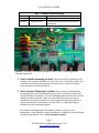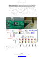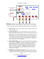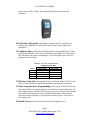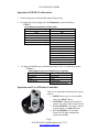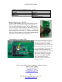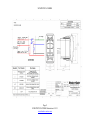
1
SCM-PD-PLUS-COMBO
SCM-PD-PLUS shown with optional SCM-WC-SN wireless controller installed
SCM-Power Distribution PLUS-COMBO system, Installation and User
Instructions:
Page 1
SCM-PD-PLUS-COMBO Instructions 2-5-15
www.shadow-caster.com
SCM-PD-PLUS-COMBO
SCM-PD-PLUS-COMBO includes:
1ea
1ea
6ea
4ea
1ea
1ea
NEMA Box with Power distribution Board and 6 outputs
Box Lid and 6 screws
7.5 Amp Fuses (Installed)
SS 316 PH,#8 x1/2" Mounting Screw
Pre-wired Lighted, OFF/ON, Momentary Switch
2 Button Waterproof Key FOB
1ea
1ea
1ea
1ea
1ea
Wireless Receiver Stamp Electronics Board
Stubby 1/4 Wave Antenna
5" SMA to U.FL Coax Jumper
90 Degree Male to Female SMA Adapter
Shadow-Caster Lanyard
Tools Required: Phillips head screwdriver, wire strippers, .257"-.261” (F or G) Diameter
Drill, and RTV for sealing the antenna bulkhead.
The Shadow-Caster Power Distribution PLUS (SCM-PD-PLUS) provides a convenient
way to connect and control multiple Shadow Caster Lights. The incorporated ShadowNet communications enables compatibility with Shadow-Caster’s color changing and
single color lights. The SCM-PD-PLUS-COMBO includes a wireless controller for
remote control of Shadow-Caster lights.
The SCM-PD-PLUS has “on board” power switching, for 6 lights and up to 100 amps.
Each light is individually switched and has its own fuse. The “on-board” power switching
feature greatly simplifies installation by allowing the power to be taken locally from a
main breaker, as opposed from the helm. The lights are controlled with a pre-wired
waterproof switch.
Shadow-NET is a communication protocol that allows the SCM-PD-PLUS to
communicate with and coordinate the color changing feature of all Shadow-Caster color
changing lights. The SCM-PD-PLUS is also fully compatible with Shadow-Caster single
color lights. The SCM-PD-PLUS will support a full range of color changing, fading,
strobing, flashing and chase modes.
Installation Steps
1. Configure the SCM-PD-PLUS: Set the 6 position dip switch (SW3) and
the 3 position switch (SW2). On SW3, each switch enables corresponding
channels 1 through 6. The install locations do not have to be consecutive. SW2,
(three position switch), functions are listed below. The SCM-PD-PLUS comes
pre-configured with network communications enabled, “chase mode” disabled,
and standard color range selected. See Picture 1.
Page 2
SCM-PD-PLUS-COMBO Instructions 2-5-15
www.shadow-caster.com
SCM-PD-PLUS-COMBO
SW2, 3 Position Switch Settings
Switch 1
Switch 2
Network Enable
Chase Mode
Switch 3
Extended Colors
Enables Shadow-Net
Enables Chase Mode
Moves Color Support from 4 to 12 (only
works with Accent Lighting Controller and full
color SC-40s
Programming Button
Location of remote
bypass jumper
SW2 Mode switches
SW3 Enable switches
Picture 1: PD-PLUS box showing locations of SW-2, SW-3, remote bypass and
Programming button.
2. Find a suitable mounting location: This box should be mounted in a dry
location, such as high in the bilge area, below the deck or inside the console. It is
preferred to not have the cable glands or the power wire connector facing up
where moisture will drain into the box.
3. Select Antenna Mounting Location: Once the power distribution box
mounting location and orientation has been selected, a suitable location for the
antenna should be determined. The ideal mounting option will have the Antenna
mounted as high as possible, and as far as possible from large metal objects.
Additionally, the antenna should be as far as possible from potential sources of
electrical interference and oriented vertically. There is a right angle adapter
included to increase mounting options.
If a suitable mounting position still cannot be found, or if there is poor
performance, contact Shadow-Caster regarding the availability of a remote-mount
extended range antenna. Part # SCM-Antenna-Extended
Page 3
SCM-PD-PLUS-COMBO Instructions 2-5-15
www.shadow-caster.com
SCM-PD-PLUS-COMBO
4. Mount Antenna in box: Verify that the 5" SMA to U.FL Coax Jumper will
reach from the Antenna PCB to the chosen location. Once Verified, drill a
slightly larger than .25” diameter hole through the PD-PLUS box. Exercise
Caution to not damage any components on the PCB. Install the SMAbulkhead with included nut and washer. Use RTV or silicon to seal around the
SMA bulkhead. Screw in stub antenna to the bulkhead.
5. Insert Wireless Card into PD-PLUS: Simply slide the Wireless Card as shown
in Figure 1. If the U.FL connection to the board has become disconnected, simply
press together to snap back on.
Diagram 1: Typical installation of SCM-PD-PLUS, shown with 6 Color Caster Lights.
(Note that Green Wire from Color Casters are not connected)
Page 4
SCM-PD-PLUS-COMBO Instructions 2-5-15
www.shadow-caster.com
SCM-PD-PLUS-COMBO
IN S T A L L J U M P E R
1 2 3
PD-PLUS
BOX
Power Switch Bypass
Push Button Switch
Optional
5
ON
Shadow-NET(H)
Shadow-NET(L)
GND
12V+ In Switched
Indicator LED(-)
Push Button
6
6 P o s i ti o n D i p S w i tc h :
S e t to O N w h e n
10V-30VDC
L ig h t is
p re s e n t
FUSE or
Located at connection to
Circuit
power source
2. (OFF) Chase mode Enable
3. (OFF) Color Range
Light Position Setup (SW3)
1. (ON) Color Caster Installed
3. (ON) Single Color Light Installed
4. (ON) Single Color Light Installed
ON
5. (OFF) No Light Installed
1 2 3 4 5 6
2
1. (ON) NetworkEnable
2. (ON) Color Caster Installed
Breaker
3
Mode Setup (SW2)
6. (OFF) No Light Installed
PWR(+)
Light 4
Light 3
Light 2
Light 1
GND(-)
Diagram 2: Optional wiring Configuration for SCM-PD-PLUS shown with Color
Caster Lights on locations 1 and 2, Single Color Lights on locations 3 and 4. Note that
the jumper on the upper left corner of the board is installed for this power configuration.
6. Mount the Box: The box can be mounted with the included #8 stainless steel
pan head mounting screws.
7. Connect the Lights: Loosen the cable glands and route the cable through.
Strip the outer cable pack approximately 1.5 inches, and the ends of the wire back
approximately .25 of an inch. The connectors are color coded. Insert each wire
into the respective location and snap the connector down. Note that the green wire
from the Color-Casters is left unconnected. The blue connector is for the blue
wire on Shadow-Caster single color lights. Note that the lights should typically be
connected consecutively for implementation of chase modes. (I.e. light moves
from one light to the next in a linear pattern).
8. Connect Input Power: Route power into the box directly from a breaker, or
main fuse panel. See Diagram 1. The breaker and incoming wire should be sized
appropriately to the number and current draw of the lights being connected.
Pwr(+) and Gnd(-) are clearly marked on the printed circuit board. The power
connector will accept from 2awg to 20awg wire. For installations where it is
desired to switch the power directly, see Diagram 2. Installation of the blue
jumper on the upper left hand corner of the board will be necessary for this
configuration. See Picture 1.
9. Install the pre-wired switch: Diagram 1 shows the pre-wired switch
configuration. The switch power can be taken from the same source as the lights
or from a local source at the installation of the switch. The current draw for the
Page 5
SCM-PD-PLUS-COMBO Instructions 2-5-15
www.shadow-caster.com
SCM-PD-PLUS-COMBO
switch circuit will be 250mA. See attached drawing for dimensions and
schematic.
10. Cinch the cable glands: Hand tighten all cable glands. Verify that any
unused cable glands have a nylon dowel inside so that a water-tight seal is
maintained.
11. Configure Fuses: The Power Distribution box comes standard with 7.5Amp
fuses to accommodate Color-Casters and SCM-10 size lights on a 12Volt power
bus. If different size lights or installing on a 24Volt bus please see Chart 1 for
appropriate fuse selection.
Chart 1: Fuse Recommendations
model
SC-40
SC-10
SC-6
SC-4
Suggested Fuse Size
12V system
24V system
30
7.5
5
3
15
3
3
3
12. Wireless Controller: If Installing Wireless Controller Model SCM-WC-SN,
please see the documents included for installation and operating instructions.
13. Final Setup and Auto Programming: Power up the SCM-PD-PLUS box.
Press and hold the “auto programming” button for three seconds and release. All
of the lights will turn off, then cycle back on one at a time, starting with light one.
The system will communicate with each light and determine what is present.
Once this process completes, cycle the power to the box again. The system is
now ready to use.
14. Install Cover: Install clear enclosure lid with 6 supplied screws.
Page 6
SCM-PD-PLUS-COMBO Instructions 2-5-15
www.shadow-caster.com
SCM-PD-PLUS-COMBO
Operation of PD-PLUS with switch:
1. Turn on the power switch and the lights will power up.
2. To change the color, simply press the Momentary switch and release.
Chart 2:
Press Momentary Button to Change Color
Normal Color setting
Extended Colors Enabled
Blue
White
Red
Green
Blue/White (fade mode only)
All colors (fade mode only)
Blue
White
Red
Green
Super White (all LEDs On)
Aqua
Blue-Violet
Violet
Magenta
Yellow
Purple
Orange
Green Yellow
Blue/White (fade mode only)
All colors (fade mode only)
3. To Change the MODE press and hold the switch in for 2 seconds then release.
Chart 3:
Change Mode: Press and hold button for 2 seconds
Normal Mode Settings Chase Mode Enabled
On Normal
Fade
Flash/Strobe
On Normal
Fade
Flash/Strobe
chase between all lights
Operation and Use of Wireless Controller:
There are 4 commands issued from the remote
control.
1. MODE: Press to go to next available
color. See Chart 2 above.
2. CONTROL: Changes the speed of a
routine. (No effect when on solid color)
3. Holding MODE for 2 seconds: Moves
to next routine, see Chart 4 below.
4. Hold CONTROL for 2 seconds:
Powers off all lights, and puts the
system into standby.
Page 7
SCM-PD-PLUS-COMBO Instructions 2-5-15
www.shadow-caster.com
SCM-PD-PLUS-COMBO
Chart 4: Press and hold MODE button for 2 seconds
Normal Mode Settings
Chase Mode Enabled
On Normal
Fade
Flash/Strobe
On Normal
Fade
Flash/Strobe
chase between all lights
Replacing the battery in the FOB:
The Key FOB transmitter uses a CR2032 lithium coin cell
battery. These are commonly available where batteries are
sold. To replace the battery, remove the two Phillips head
screws on the back of the transmitter. The battery slides out
as shown in figure 10. Be careful to have the “+” side of the
battery facing as shown in figure 10. When reassembling the
FOB case, exercise caution to verify that the watertight seal
is properly seated on the perimeter of the case.
Programming a new remote FOB:
Programming Button
If the remote FOB must be replaced,
the new one can easily be coded to
the wireless receiver. To do this,
power on the PD-PLUS system, then
press the programming button on the
receiver and release. Then press and
release the MODE button on the
wireless receiver, repeat this until the
code is picked up by the receiver.
This can be verified by seeing the
Shadow-Caster Lights changing
color. Note that the wireless
controller will only support one
remote at a time.
Please contact Shadow-Caster Lighting for additional support:
Shadow-Caster Lighting
1237 Lady Marion Lane
Dunedin, FL 34698
[email protected]
727-474-2877
Page 8
SCM-PD-PLUS-COMBO Instructions 2-5-15
www.shadow-caster.com
SCM-PD-PLUS-COMBO
Page 9
SCM-PD-PLUS-COMBO Instructions 2-5-15
www.shadow-caster.com
SCM-PD-PLUS-COMBO
Page 10
SCM-PD-PLUS-COMBO Instructions 2-5-15
www.shadow-caster.com