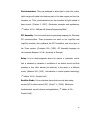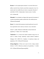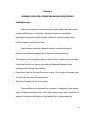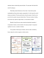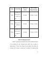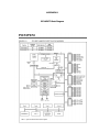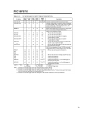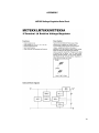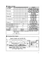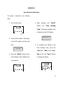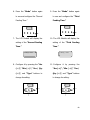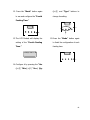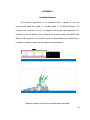
1
Microcontroller Based Fish Feeder
By
Patrick Henry G. Baniqued
Martin Joseph C. De Castro
Chael Triston T. Luzano
A Design Report Submitted to the School of Electrical Engineering,
Electronics and Communication Engineering, and Computer
Engineering in Partial Fulfilment of the Requirements for the Degree
Bachelor of Science in Computer Engineering
Mapua Institute of Technology
January 2009
ii
ACKNOWLEDGEMENT
First of all, the group members would like to thank the Almighty Father, for
giving them knowledge, strength to carry on, and patience to finish this design.
Likewise, they are very grateful to the following persons: hence, Engr. Noel B.
Linsangan, for approving their proposed design, and for citing examples on how to
improve the device and how to put it in good use;
The two important women in the team, their advisers, Engr. Annalyn Yumang
and Engr. Maribelle Pabiania, for being with them throughtout the duration of the
design;
And lastly, their beloved parents, for giving them the spiritual and financial
support they need to finish this design.
PH G. Baniqued
MJ G. De Castro
CT T. Luzano
iii
TABLE OF CONTENTS
TITLE PAGE
i
APPROVAL SHEET
ii
ACKNOWLEDGEMENT
iii
TABLE OF CONTENTS
iv
LIST OF TABLES
vi
LIST OF FIGURES
vii
ABSTRACT
viii
Chapter 1: DESIGN BACKGROUND AND INTRODUCTION
Design Setting
Statement of the Problem
Objective of the Design
Significance of the Design
Conceptual Framework
The Scope of Delimitation
Definition of Terms
1
1
2
3
3
4
6
8
Chapter 2: REVIEW OF RELATED LITERATURE AND RELATED STUDIES
Automatic Fish Feeder
Type of Feeds
Types of Fish
Automatic Fish Feeder
14
14
17
18
20
Chapter 3: DESIGN METHODOLOGY AND PROCEDURES
Design Methodology
Project Design Flowchart
Design Procedure for Actual Design
Hardware Design
Block Diagram
Schematic Diagram
List of Materials
Software Design
23
23
23
25
27
27
28
29
30
iv
System Flowchart A
System Flowchart B
Prototype Development
30
31
32
Chapter 4: TESTING, PRESENTATION, AND INTERPRETATION OF DATA
37
Chapter 5: CONCLUSION AND RECOMMENDATION
Conclusion
Recommendation
Bibliography
54
54
54
56
Appendices
57
APPENDIX A – Source Program
APPENDIX B – List of Materials
APPENDIX C – PIC16F87X Data Sheet
APPENDIX D – PIC16F87X Block Diagram
APPENDIX E – LM7805 Voltage Regulator Data Sheet
APPENDIX F – LCD Module
APPENDIX G – User Manual
APPENDIX H – Installation Manual
57
67
69
72
74
76
79
82
v
LIST OF TABLES
Table
Table
Table
Table
Table
Table
Table
Table
Table
Table
Table
Table
Table
3.1:
4.1:
4.2:
4.3:
4.4:
4.5:
4.6:
4.7:
4.8:
4.9:
4.10:
4.11:
4.12:
List of materials
Testing of Container 1
Testing of Container 2
Testing of Container 3
Default Setting of each Feed
Pellets Feed
Flakes Feed
Powder Feed
Trial 4
Trial 5
Trial 6
Capacity of Each Feed
Release of Feeds
29
38
39
40
41
43
44
45
47
48
49
50
52
vi
LIST OF FIGURES
Figure
Figure
Figure
Figure
Figure
Figure
Figure
Figure
Figure
Figure
Figure
Figure
1.1:
2.1:
3.1:
3.2:
3.3:
3.4:
3.5:
3.6:
3.7:
3.8:
3.9:
3.9:
Conceptual Framework
Types of Mechanical Feeder
Design Procedure
Block Diagram
Schematic Diagram
System Flowchart A
System Flowchart B
The Containers
The Controller
Ideal State
Mode State
Switch
4
15
25
27
28
30
31
32
33
34
34
36
vii
ABSTRACT
The design is all about the microcontroller-based fish feeder. The
microcontroller-based fish feeder is very useful in providing people who
are always away from their home to have their fish fed regularly and on
time keeping the fish healthy and safe. The main purpose of this design is
the automation of the fish feeding device with accurate and precise set
time of feeds to be released, the usage of LCD monitor for user interface,
the implementation of alarm or signal to know if the container is almost
empty, and the use of relay as electronic switch for the dc motor. This
design will be installed in aquariums, operated and controlled by a PIC
microcontroller. It is operated by inputting the real time and assigning a
desired time the fish will be fed which will be displayed on the LCD.
Keywords: fish feeder, microcontroller, LCD monitor, Alarm or Signal, Relay
viii
Chapter 1
DESIGN BACKGROUND AND INTRODUCTION
Design Setting
Automation is defined as self-regulating control of equipment,
systems or processes without human intervention. These ideas of
automation hold favor with those technologists and lazy people who do
not want to do tough work particularly manual operations. The scientific
wizardry of achieving automations undoubtedly makes it apparent that the
day will surely come when all of the things will be automatically operated.
It is true that most fish can miss a meal without being in any
danger. Some fishes can easily go a week or more without food if they
are healthy. As fish owners, it will determine how they are concerned
about their fish while being away for an extended period of time.
In addition, having to design and manufacture a fish feeder that
can greatly assist fish farmers and the productivity of the farm can help
them operate more without bearing too much of a cost on other things.
The design project is that it will be also very inconvenient on the
part of the owners when on vacation and for those living a busy lifestyle
1
because some sensitive and expensive fish normally need to be fed once
or twice a day.
Thus, the purpose of the design project was to provide the fish
owners a device that can actually feed their fish regularly whenever they
are away or on a vacation for a while. These reasons led to the invention
creation of an automatic fish feeder.
Statement of the Problem
Different fish have different diets, depending on what food they
eat. Available designs of automatic fish feeder have only one container so
the device is only good for one fish, or it will depend on what food is it the
container. Also, if there are different kinds of fish in a certain aquarium,
that feeder will be useless because the device cannot accommodate or
release different kinds of feed at the same time. In addition, other fish
feeders releases foods in a fixed amount causing some of the food to
become just a waste in the aquarium, or if the fish have a bigger diet,
there is a tendency that the food will not be enough. These problems
resulted in certain inquiries:
1. How can a device feed different kinds of fish on a single container?
2. How can a user-friendly device be developed?
2
3. How can it release different kinds of food at the same time with
different amount?
4. How can an exact and accurate amount of food for the fish be
released?
5. How can the time and the amount of food to be released by the
device be controlled?
Objective of the Design
The primary objective of the design was to create a device that
would automatically feed the fish via a microcontroller in the aquarium.
This would include having an accurate process like time setting and
regulated amount of feeds to be released. In addition, since there are
different kinds of fish in a certain aquarium, the device will release three
different kinds of feed such as pellets, flakes and, powder either at the
same time or separately. For ordinary fish owners, the device will come
very simple and easy-to-use. Feeding the fish in the aquarium regularly
and on time is taxing, that is why designing an automatic fish feeder can
help ease up the task.
Significance of the Design
The design will aid in providing information in the development of
microcontroller-based fish feeder. These can also help the students to
3
have a background on micro-controller based devices to help them
improve
or
develop
some
industrial
controller
based
products.
Furthermore, creating the device will help in promoting the school’s
technological advancement through the innovation of different kinds of
equipment via a micro-controller. Creating the device can also identify
some of the advantages and disadvantages of using this kind of process
by analyzing how the fish will react and grow when given enough amount
of food. These will also help some designers to know or to see if there are
still ways on how to improve the device depending on how it will affect
the fish or the environment.
Conceptual Framework
Input
Process
- Power
Microcontroller
- Push button
- Timer set
(Time set, qty set, &
mode set)
- Amount set
- Reset mode
Sensor
- Fish Food
- Phototransistor
and LED
Output
- LCD
- Releasing of
Food
- Alarm (if the
container is empty)
Figure 1.1 Conceptual Framework
4
Figure 1.1 presents the conceptual framework of the design. The
input variables will be done by the client or user. First, the user will turn
on the power for the device to work. Afterwards, the user will set the time
on when the food will be released and the amount of food to be given.
After that, the user will put the fish food on specific containers. Different
kinds of food will be placed on separate containers for easy identification.
These kinds of food are the pellets, flakes and powder. A push button is
used to select the appropriate data. From the input variables, it will now
go to its processing stage upon which the microcontroller will process the
time of release as well as the amount of food. The machine will also
release the food on a random or fixed place of location in the aquarium.
The reset mode is an automatic process in case of a power failure. The
sensor acts independently in the prototype. A signal from the
phototransistor will be processed after sensing the LED. After the
processing stage, the food will be released as the output stage of the
machine. The LCD will act as the visual representation of the device
displaying the set time and amount of food making the device userfriendly. An alarm will activate whenever the containers are almost empty.
5
Scope and Delimitations
The scope covers the lists of capabilities that a microcontroller-based
fish feeder can perform while limitations are the operations that the
device is restricted to execute because it is outside the boundaries of the
project.
This part of the design opens an inventor’s mind for further
research study.
The scope of the design includes the following:
1. Automation of fish feeding device was mainly controlled by the PIC
microcontroller.
2. Pushbuttons were used for accuracy and precision to set time to
release or discharge feeds.
3. LCD monitor was used as user output interface.
4. Phototransistor was used as a sensor to indicate that the container
has amount to be emptied.
5. Three relays were used as electronic switch for the dc motor to aid
the dispensing of feeds from the container.
6. Three containers were controlled. One, two or three containers can
be set to release feeds one at a time or all at the same time.
7. The amount of feeds depends on the rotation of the plate
underneath the funnel. Based on the testing 0.1 gram per rotation
for pellets and powder while 0.05 gram per rotation for flakes.
6
For the delimitations:
1. The prototype was limited to the kind of feeds placed on the
container. The feeds may vary only with pellets, flakes, and
powder.
2. The design was capable of releasing feeds at the set time. Thus, it
does not matter even if there are still foods on the aquarium it will
still release feeds on the given time. It will depend on the user to
set time in order not overfeed the fish or turn the feeds into a
waste.
3. The first two limitations compensated for the third limitation. The
kind of feeds and the amount of feeds that the device can release
is controlled. Basically, one fish will not benefit using the
microcontroller-based fish feeder. Same with any fish that does not
eat the three given kinds of feeds.
4. The size of the location for the device could be used in an
aquarium or in an outdoor mini-fishpond.
5. The device could not operate during black-out or brown-out and all
data will be reset.
7
Definition of Terms
Accuracy. It is the degree of agreement between the experimental result
and the true value. (Britannica Encyclopedia)
Alarm. It refers to a signal (as a loud noise or flashing light) that warns
or alerts. (Merriam Webster Dictionary)
Aquarium. It is a container (as a glass tank) or an artificial pond in
which living aquatic animals or plants are kept. (Merriam Webster
Dictionary)
Aquarium fish feeders. They are electric or electronic gadgets designed
to feed aquarium fish at regular intervals. They are often used to feed fish
when the aquarist is on vacation or is too busy to maintain a regular
feeding schedule. (Sanford, G. (1999). Aquarium Owner's Guide. New
York: DK Publishing.)
Capacitor. It is a passive element designed to store energy in its electric
field, the most common electrical components. It is consisted of two
conducting plates separated by an insulator (or dielectric). It is an open
circuit to dc used extensively in electronics, communications, computer,
and power systems. (Alexander, C.; Matthew S. (2003). Fundamentals of
electric circuits, 2nd edition. New York: McGraw-Hill)
8
Crystal Oscillator. It refers to an electronic circuit that uses the
mechanical resonance of a vibrating crystal of piezoelectric material to
create an electrical signal with a very precise frequency. (Floyd T.L.,
(2006). Electronics fundamentals: circuits, devices and applications, 7th
edition. U.S.A.: Prentice Hall.)
DC Motors. They are extremely versatile drives capable of reversible
operation over a wide range of speeds, with accurate control of speed at
all times. (Robert N. B. (2001). Introduction to control system technology,
7th edition. U.S.A.: Prentice hall.)
Fish. They are aquatic vertebrate animals that are typically ectothermic
(cold-blooded), covered with scales, and equipped with two sets of paired
fins and several unpaired fins. (Nelson, S. (2006). Fishes of the world.
John Wiley & Sons, Inc.)
Fish Food. It can be plant or animal material intended for consumption
by pet fish kept in aquariums or ponds. Fish foods normally contain macro
nutrients, trace elements and vitamins necessary to keep captive fish in
good health. (Riehl, R. and Baensch, HA. (1996). Aquarium Atlas.
Germany: Tetra Press.)
Flowchart. It is a graphical representation of a process, such as a
manufacturing operation or computer operation, indicating the various
9
steps that are taken as the product moves along the production line or the
problem moves through the computer. (Boillot M.H., Gleason G.M., Horn
L.W. (1997). Essentials of flowcharting, 5th edition, U.S.A.: William C.
Brown Pub)
Heatsink. It is an environment or object that absorbs and dissipates heat
from another object using thermal contact (either direct or radiant). Heat
sinks are used in a wide range of applications wherever efficient heat
dissipation is required. (Flanagan, W.M. (1993-01-01). Handbook of
transformer design and applications. U.S.A.: McGraw-Hill Professional)
LCD (Liquid Crystal Display). It is a thin, flat display device made up of
any number of colors or monochrome pixels arrayed in front of a light
source or reflector. It is often utilized in battery-powered electronic
devices because it uses very small amount of electric power. (Alexander C.
and Sadiku M. (2003). Fundamentals of electric circuits, 2nd edition.
U.S.A.: McGraw-Hill)
LED (Light Emitting Diode).
It is a semiconductor diode that emits incoherent narrow-spectrum
light when electrically biased in the forward direction of the p-n junction,
as
in
the
common
LED
circuit.
This
effect
is
a
form
of
electroluminescence. (Charles S. (2007). Electronics principles and
applications, 7th edition. U.S.A.: McGraw-Hill Science/Engineering/Math )
10
Microcontroller. It is a single chip that contains the processor (the
CPU), non-volatile memory for the program (ROM or flash), volatile
memory for input and output (RAM), a clock and an I/O control unit. And
it is called a "computer on a chip". (James L.A. (2006). The Intel®
microprocessor family: Hardware and software principles and applications.
U.S.A.: Delmar Cengage Learning)
MPLAB. MPLAB Integrated Development Environment (IDE) is a free,
integrated
gcc-based
toolset
for
the
development
of
embedded
applications employing Microchip's PIC and dsPIC microcontrollers.
(MPLAB User Manual)
OrCad. It is a proprietary software tool suite used primarily for electronic
design automation. The software is used mainly to create electronic prints
for manufacturing of printed circuit boards, by electronic design engineers
and electronic technicians to manufacture electronic schematics and
diagrams, and for their simulation. (ORegonCAD User Manual)
PCB (Printed Circuit Board). It is used to mechanically support and
electrically connect electronic components using conductive pathways, or
traces, etched from copper sheets laminated onto a non-conductive
substrate. (PCB Design by Chris Stahl)
11
Phototransistors. They are packaged to allow light to enter the crystal.
Light energy will create hole-electron pairs in the base region and turn the
transistor on. Thus, phototransistors can be controlled by light instead of
base current. (Charles S. (2007). Electronics principles and applications,
7th edition. U.S.A.: McGraw-Hill Science/Engineering/Math )
PIC Assembly. It is the lowest-level programming language for Microchip
PIC microcontrollers. These processors are used on the LogoChip and
LogoChip modules, the LogoBoard, the PIC Foundation, and every layer in
the Tower system. (Covington M.A. (1999). PIC Assembly language for
the complete Beginner. U.S.A.: University of Georgia)
Relay. It is an electromagnetic device for remote or automatic control
that is actuated by variation in conditions of an electric circuit and that
operates in turn other devices (as switches) in the same or a different
circuit. (Bateson R.N. (2001). Introduction to control system technology,
7th edition. U.S.A.: Prentice hall.)
Rectifier Diode. It is an electrical device that converts alternating
current (AC) to direct current (DC). (Floyd T.L., (2006). Electronics
fundamentals: circuits, devices and applications, 7th edition. U.S.A.:
Prentice Hall.)
12
Resistor. It is the simplest passive element. It is a device that has the
ability to resist the flow of electric current that is measured in ohms. It is
usually made from metallic alloys and carbon compounds. (Alexander C.
and Sadiku M. (2003). Fundamentals of electric circuits, 2nd edition.
U.S.A.: McGraw-Hill)
Schematic. It is a schematic is a diagram that represents the elements of
a system using abstract, graphic symbols rather than realistic pictures.
(Britannica Encyclopedia)
Sensor. It is a device that measures a physical quantity and converts it
into a signal which can be read by an observer or by an instrument.
(Floyd T.L., (2006). Electronics fundamentals: circuits, devices and
applications, 7th edition. U.S.A.: Prentice Hall.)
Transformer. It is a device that transfers electrical energy from one
circuit to another through inductively coupled electrical conductors.
(Flanagan W.M. (1993-01-01). Handbook of transformer design and
applications. U.S.A.: McGraw-Hill Professional)
Voltage Regulator. A Diode can be used to hold a voltage constant.
(Charles S. (2007). Electronics principles and applications, 7th edition.
U.S.A.: McGraw-Hill Science/Engineering/Math )
13
Chapter 2
REVIEW OF RELATED LITERATURE AND RELATED STUDIES
Feeding Devices
There are a number of mechanical aids to hand feeding and many types
of automatic feeders on the market. Automatic feeders are particularly
appropriate to intensive systems and the feeding of nursery fry tanks which
require frequent, small doses of feed.
Some feeders, particularly demand feeders, are relatively easy to
construct using simple materials like oil drums or plastic containers.
•
The amount of food that will be given to the fish can be measured or controlled.
In that way the fish can have a good and well balanced diet and a clean
aquarium that can keep them healthy.
•
Feeders can feed the fish even the owner is away. This is a very convenient way
for the people who are very busy at work.
•
The time of feeding the fish is controlled.
These devices can be grouped into a number of categories. Some require
mains or battery electrical power. Some rely on water power while, others on the
weight of the feed and the action of the feeding fish. A good example of
14
stationary device is electrically powered feeder. The automatic fish feeder falls
under this category.
Electrically powered feeders are of two kinds - those which operate
mechanically and those which employ compressed air. In both cases the control
devices are electrical. The time and duration (thus the amount of feed) can be
pre-set by the operator using an electrical timer. This may be mains or battery
driven and it may operate a single feeder or a whole bank of feeders.
Basically, though there are many variants and patented examples of
compressed air feeders, most are based on the same principle. A compressor
supplies air to one or a number of feeders.
The operation of these types of feeders, which are also controlled by
timers, depends on electro-magnets or electric motors.
Type C
Type B
Type A
Type E
Type F
Type D
Type G
15
Figure 2.1 Types of Mechanical Feeders
Type A (Figure 2.1). Movement of the slug is controlled by an electro-magnet.
The space governs the amount of feed released at each movement of the slug.
Type B (Figure 2.1). Here the feed through consists of two parts, one inside the
other. The movement of the inner one is controlled by an electro-magnet. When
the holes in the two parts of the feeder coincide, the feed falls through.
Type C (Figure 2.1). In this version the feed falls from the hopper on to a disc
which is rotated by an electrical motor at intervals to eject a portion of feed. The
motor also releases the feed from the hopper on to the disc by operating a valve.
The feed can either be released directionally, using the guide shield or, if the
latter is removed, throughout a 360 angle.
Type D (Figure 2.1). A series of spikes on a revolving spindle overturns a row of
feed containers in turn. The frequency depends on the speed of revolution of the
spindle.
Type E (Figure 2.1). An endless screw mechanism transfers the feed from the
hopper to the outlet. The amount of feed released depends on the number of
revolutions of the motor drive screw, which is controlled by a timer as is the
periodicity of feeding.
16
Type F (Figure 2.1). Similar to type D except that a blower is added, which
distributes the feed over a greater distance.
Type G (Figure 2.1). The feed is delivered on a conveyor belt driven, at selected
intervals, by a motor controlled by a time switch.
The microcontroller-based Fish feeder falls under type A but instead of a
slug it is replaced by a rotating disc. The hole of the disc governs the amount of
feed released at each rotation of the disc. (Michael, 1987)
Types of feeds
Most
commonly,
fish
food
can
be
divided
into
3
main
categories:
1. Manufactured food. This includes floating and sinking pellet, granular and
flake food.
2.
Freeze-dried
feeds.
Worms,
larvae,
brine
shrimp
and
krill
etc.
3. Live foods. Maggots, fresh insect larvae, live worms, and feeder fish – all
come under this category.
The microcontroller-based fish feeder uses manufactured foods. The
prototype can released flakes, granules, and pellets from the container.
Flake food refers to a kind of food that is most commonly eaten by both
marine as well as tropical freshwater fish. This is ideally suited for top dwellers
17
and mid-water fish. Once the flake food has settled down, it can be eaten by the
bottom dwellers, too. If one’s aquarium consists of bottom dwellers mainly, it
would be a good idea to pre-soak the flake food so that it will sink to the bottom
as soon as it is introduced into the water.
Pellets come in various sizes and shapes, suited for fish of different sizes.
Pellet fish foods come in many different types for the growth of wens, color
enhancer and other things. They also come in sinking and the floating kind.
Granular feed needs to be used only if the bottom feeders are not getting
enough sunken flakes or seem hungry. Bottom dwellers often need to be fed
separately, so granular food is ideal for this kind of fish. (Michael, 1987)
Regardless of the type of foods to feed the fish, a variety of foods should
be provided. Variety in the diet reduces the chance of any nutritional
shortcomings of one or more of the selected foods becoming a health or
longevity problem for the fish. Providing a variety of foods will also reduce the
chances that the fish lose interest in the foods that they are offered and go on a
"hunger strike." (Mark, 2004)
Types of fish
As we all know, not all fish eat the same kind of feeds. There are some
fish that eat pellets, granules and/or flakes while others eat small fishes. But the
types of fish that will benefit the design come from the types of feeds that are
18
used in the microcontroller-based fish feeder container to be released and these
are pellets, granules and flakes.
According to Shirlie (2001), fish are classified on their dietary or
preferences of what they eat. The classifications are carnivores, herbivores, and
omnivores.
Carnivores are meat-eating fish. Some prefer live prey that they can hunt
down and kill before eating, such as other fish or insects.
Herbivores require a diet of all, or most likely, vegetable matter. True
herbivores do not have a large stomach, and therefore must eat more
frequently. Some herbivores may learn how to eat other foods like flakes and
pellets.
The majority of aquarium fish are omnivores, meaning they will eat both
meat and vegetables. To keep the fish healthy, they must be fed with a varied
diet that includes all types of foods. Here are some popular omnivores, with
notes about their preferred diet.
Angelfish - accepts all types of foods, but prefers live foods.
Goldfish - accepts all types of foods, but diet should not be too high in protein.
Gourami - accepts all types of foods, but prefers additional meat in the diet.
Guppy - accepts all types of foods, but prefers mosquito larvae.
19
Koi – accepts flakes, pellet and live foods.
Kribensis - accepts flakes, pellets and live foods.
Mbuna - accepts flakes, pellets and live foods.
Orandas – accepts flakes, pellets and live foods.
Rams - accepts flakes, pellets and live foods.
Severum - accepts flakes, pellets and live foods.
Zebra Danio - accepts flakes, pellets and live foods.
Automatic Fish Feeder
The present design relates to a device for automatic feeding of fish in fish
cages.
Automatic feeding devices for fish cages exist in different designs adapted
according to specific parameters like the nature of feed, the species of the fish,
etc. Automatic feeding devices on the market today are mainly based on the use
of dry feed (dry pellets) and the feeding is carried out on the water surface. This
technology is not desirable for feeding of pellets based on wet feed, soft feed or
gel feed which should be stored and handled together with water: fresh- or
seawater. (Newton, 2001)
20
Another important condition is that some fish species prefer the feed
"served" on a certain depth and not at the surface.
Previously automatic feeding devices have been used for wet feed, but
not based on feeding of wet pellets. This technology was based on a pellet
machine being placed by/above the fish cage and the pellets being produced and
dropped directly into the water surface of the fish cage. This technology cannot
be used just like that for the feeding of readymade pellets based on wet feed,
soft feed or gel feed.
There exists a need for a controlled and automatic feeding of readymade
pellets for fish feed based on wet feed, soft feed or gel feed. An automatic
feeding device in this connection should comprise a complete concept which
makes it possible to store the pellets submerged in sea- or freshwater as well as
a controlled and automatic feeding under water. (George, 2001)
The Human Fish Feeder/House Sitter
If, instead of a mechanical feeder the fish owner chooses to arrange for
someone else to stop into the house to check on things and also feed the fish,
the following are words of warning and suggestions to keep the fish safe while
the owners are out of town. First off, pre-measure all the food. Do not give a
novice fish keeper a big can of food and expect to come home to anything but a
tank full of dead fish and a mass of rotting excess food at the bottom of the
21
aquarium. Instead, use the little containers that one can buy at the local drug
store which are designed to hold daily doses of medication. They have seven
small, separate compartments and are marked for each day of the week. These
are perfect for holding small amounts of dry fish food. If the fish also receive
frozen food, purchase the frozen food that comes in little cubes (like small ice
cube trays) and tell the house sitter exactly how many cubes of food per day.
Alternatively, one could purchase a second pill container and placed portions of
large slab frozen foods in each compartment.
Last, hide the rest of the fish food. Do not leave cans sitting around the
tank. Inevitably, the part-time novice fish feeder will feel that the fish are not
getting enough to eat and will feel some sort of compulsion to give them more.
Help them resist this urge by removing and hiding the food reserves and force
them to stick with the rationed portions. (Evans, 1998)
22
CHAPTER 3
DESIGN METHODOLOGY AND PROCEDURE
Design Methodology
This type of design is a constructive research which means that it
develops solutions to a problem that has to be solved through the development
of a system. The group needs to find ways on how to automate a fish feeding
device that is usually done in manual process. The automation should include
accuracy of time, amount of food to be given, indication of the food in the
container if it is almost empty, and the interface of the user to the machine.
Project Design Flowchart
Figure 3.1 defines the procedure in developing the design. Identifying the
problem would be the first step. In this case, brainstorming is done on how to
come up with the design project was done. Questions on how the group could
automate a fish feeding process were asked. Is it possible to control time as well
as quantity of release of food? Is it possible to control three containers at the
same time?
The second step supported the first step. Gathering information related to
the design would help to further develop the prototype. Previous designs were
considered to know what to innovate to come up with a new design.
23
Developing a new design would include among others, sketching of
circuits and creating possible PCB layouts. Gathering information about the
needed components was necessary. Adequate research of materials to back up
the design was likewise done. Choosing the right microcontroller, LCD, relay,
motor, among others were accomplished. There were a few components that
were bought, but were not need or used during the actual creation. This was
expected in the trial and error testing of the device.
Identifying the problem
How to automate a fish feeder with 3
different containers, included time
and quantity
Drafting or outlining the possible
solution to the problem
A
24
A
Gathering information about
the materials and components
suited for the design
No
Is the
component
useful?
Yes
Start Building the prototype
STOP
Figure 3.1 Design Methodology Flowchart
The flowchart shows the points of input and output, the logic or sequence of the
various processing steps in the system, and the relationship of one element of the
system to the other parts of the system or to other information systems.
Design Procedure for Actual Design
The prototype is made up of a controller box and a container box. All
circuit components are in the controller box; from power supply, microcontroller,
to LCD monitor are in the controller box. The controller box is the user interface
of the device which contains buttons for selection in which the user will input all
the data he or she wants. The container box, on the other hand, is where the
25
feeds of the fish will be placed. It is a funnel type container in which the fish
feed will go directly to the aquarium. A rotating motor is placed underneath the
funnel to make the hole in the plate to reach the bottom of the funnel. The
motor is controlled by the relay inside the controller box.
Procedures in creating the prototype:
1. Prepare all the things needed for starting a prototype (e.g. research, materials,
etc.)
2. Use ORCAD (circuit generating software) to create a circuit design and PCB
design.
3. Create a power supply with a bridge type rectifier connected to a voltage
regulator. The rectifier will convert ac signal into dc signal. Connect it to a
voltage regulator LM7805 that will produce another voltage 5V appropriate for
some components like microcontroller and LCD monitor.
4. Prepare the microcontroller PIC16F877 for programming and burning. Burn the
PIC microcontroller using MPLAB. The generated code is located at appendix B.
5. Connect all necessary components or other circuits to the microcontroller switches for selection keys, power supply, LCD module for visual interface, and
relays.
6. Prepare the container for three different kinds of feeds.
26
Design Procedure
A. Hardware Design
DC Motor
220V Source
Transformer
Voltage Regulator
Relay
Sensor
PIC
Micro – Controller
LCD Display
Figure 3.2 Block Diagram
The PIC Micro-controller is the one responsible for showing the settings in
the LCD display for triggering the relay to the DC motor in dispensing the food,
and for activating the sensor if one of the containers is empty. It is like the brain
of the whole circuit for it processes all the controls inside the design. It can be
powered by +5 volts of voltage.
The whole design is also being powered by a voltage regulator where it
output +5 volts for the micro-controller, and +12 volts for the relay. The block
diagram shows the whole hardware implementation of the design.
27
28
Figure 3.3 Schematic Diagram of the Controller
List of Materials
PIC16F877
16 X 2 LCD
ASSTD 1/4 W Resistor (1 Pack)
8 MHz Crystal
10K Array Resistor
1200µF / 16V Elect Cap
7805 Voltage Regulator
W106 Rectifier Diode
8 Pins Connector
100µF / 25V Elect Cap
22 PicoF Ceramic Cap
105 Multilayer Cap
Relay Module
UNL2003 IC
16 Pins IC Socket
12V Relay
3 Pins Terminal Block
5 Pins Connector
DC Motor
Photo Transistor
Limit Switch
4700µF / 25V Elect Cap
PBPC Rectifier Diode
Amp Transformer
Fuse w/ Fuse Holder
AC Cord
Box Case
Heat Sink
1
1
1
1
2
2
1
1
2
1
2
1
3
3
1
3
3
1
3
3
8
1
3
1
1
1
1
1
Table 3.1 List of Materials for Microcontroller-based Fish Feeder
All of the components listed in Table 3.1 are used in creating the
microcontroller-based fish feeder. Some materials like aquarium and fiber
glass (for the 3 containers) are used to support in building the design.
29
B. Software Design
There are two systems used for the design. One is for dispensing
the food, and the other is for enabling the sensor if one of the containers
is almost empty. Both act independently from each other once the device
is turned-on.
START
Turn – on Device
No
Set time, type
and quantity
of feed?
Yes
Default Mode
Settings
Feed [1]:6:00
Type: A
Qty: 2
Feed [2]:12:00
Type: B
Qty: 2
Feed [3]:18:00
Type: C
Qty: 2
Feed [4]:22:00
Type: A
Qty: 2
Configure Time, Type and
Quantity
Dispense Food
STOP
Figure 3.4 System Flowchart A
30
Figure 3.4 shows that whenever the device is turned-on, the user
can change the default time that was set by the device. If the user
chooses not to change the configuration, the default feeding time is
shown on the flowchart, and dispenses the food according to the time
that was set on it. On the other hand, changing the setting of the feeding
time can enable the user to configure or change the time and the type
and quantity of feed to be dropped by the device before it dispenses the
foods.
Sensor Flowchart
START
Turn – on Device
Turn – off LED
No
Container
[n] almost
empty?
Yes
Turn – on LED
STOP
Figure 3.5 System Flowchart B
31
The sensor of the containers, which shows how the device reacts
whenever one of it is almost empty, is being shown on system flowchart B
(Figure 3.5). The LED will light-up, depending on what container is almost
empty, as the sensor detects it. It is entirely a different system because it
only detects the feeds inside the containers.
C. Prototype Development
The Containers
Figure 3.6 The Containers
The microcontroller-based fish feeder consists of 3 containers that
are operated using a dc motor powered by a 12V source. The amount of
32
feed given to the fish is controlled by a dc motor. While the dc motor is
spinning the disk with a small hole and when the funnel hole and the hole
in the disk met, the feeds will be dropped from the container. The amount
of feeds will be controlled by the numbers of rotation of the disks. The
sensor is placed at the funnel one inch above the tip. This will indicate
that the feed is almost empty.
The Controller
Figure 3.7 The Controller
The design consists of eight buttons that control the whole design and
each button has its own function.
1. LCD Module
2. Push Buttons
33
3. LED Alarm Signals
4. Main Switch
1. LCD Module - The LCD Module is the one responsible for displaying the
real-time, quantity of amount to be fed, type of feed to be dispensed,
and time setting of each feeding time.
Figure 3.8 Ideal State
The LCD monitor in Idle State shows the title “Fish Feeder” together with
the real time. The real time format is in military form or 24 hours: 60 minutes:
and 60 seconds.
Figure 3.9 Mode State
34
The LCD monitor in Mode State shows the following:
1. Memory Set / Mode Set
2. Qty
3. Time Set
4. Type of feeds
2. Push Buttons – There are eight push buttons on the entire controller,
and each has its own function.
Mode - The mode button allows the user to change and view the
settings of each feeding time, type of feed, and its quantity. It
also serves as memory for any user input.
Type - The type of feed button allows the user to choose
different kinds of feed to be dispensed on the container.
Sec / Qty (-+) – In configuring the real time, the user can use
this button to change the seconds of the time. Also, in configuring
the setting of each feeding time, this button can help the user
change the amount or quantity of feed to be dispensed.
Min (-+) – It is used in changing the minutes of the time, both in
real time and configuration setting of the feeding time.
Hrs (-+) – It is used in changing the hours of the time, both in
real time and configuration setting of the feeding time.
35
3. LED Alarm Signals – It represents the status of each container whether
it is almost empty or not. The LED will turn-on if one of the containers is
almost empty, and it will turn-off if it still has a feeds in it.
4. Main Switch – It is used to switch the design on or off. It is at the ON
setting if the switch is flipped upwards and OFF when flipped downwards.
Figure 3.9 Switch
The design is operated by following these steps:
1. Turn-on the device.
2. Put in the real time.
3. Put it the desired time when the feeds will be dropped.
4. Lastly, put in the type of feeds to use, and its quantity.
36
Chapter 4
TESTING, PRESENTATION, AND INTERPRETATION OF DATA
Testing
The microcontroller-based fish feeder, which can automatically feed
the fish on time, has four feeding time which means that the feeder can
perform up to four maximum memory slots for feeding. On each feeding
time, the user can change the type of feed to be dropped, the time of
dispense, and the quantity or amount of food to be release.
Accuracy of time feed
In determining the accuracy of the time set by the user, the
prototype was tested on a weekly basis. It was tested on a 15-gallon
aquarium with 7 gold fish. The 3 containers will feed, at any time interval.
By pressing the Hrs, Min, Sec/Qty, and Type buttons of the device,
the settings of each feeding time is changed. The succeeding tables show
the time and day in which the feeder will dispense. The record also shows
that at any time set, the feeder will release food for the fish.
37
Time
Monday
Tuesday
Wednesday
Thursday
Friday
Saturday
Sunday
7:00 am
Yes
Yes
Yes
Yes
Yes
Yes
Yes
10:00 am
Yes
Yes
Yes
Yes
Yes
Yes
Yes
1:00 pm
Yes
Yes
Yes
Yes
Yes
Yes
Yes
4:00 pm
Yes
Yes
Yes
Yes
Yes
Yes
Yes
7:00 pm
Yes
Yes
Yes
Yes
Yes
Yes
Yes
10:00 pm
Yes
Yes
Yes
Yes
Yes
Yes
Yes
Table 4.1 Testing of Container 1
Table 4.1 shows the testing of container 1. The time is set from
7:00am – 10:00pm with an interval of two hours. For one whole week the
prototype was observed if it would work properly or not. Based on the
data, the container 1 of the prototype worked properly.
38
Time
Monday
Tuesday
Wednesday
Thursday
Friday
Saturday
Sunday
8:30 am
Yes
Yes
Yes
Yes
Yes
Yes
Yes
11:30 am
Yes
Yes
Yes
Yes
Yes
Yes
Yes
2:30 pm
Yes
Yes
Yes
Yes
Yes
Yes
Yes
5:30 pm
Yes
Yes
Yes
Yes
Yes
Yes
Yes
8:30 pm
Yes
Yes
Yes
Yes
Yes
Yes
Yes
11:30 pm
Yes
Yes
Yes
Yes
Yes
Yes
Yes
Table 4.2 Testing of Container 2
Table 4.2 shows the testing of container 2. The time was set from
8:30am – 11:30pm with an interval of two hours. For one whole week the
prototype was observed if it would work properly or not. Based on the
data, the container 2 of the prototype worked properly.
39
Time
Monday
Tuesday
Wednesday
Thursday
Friday
Saturday
Sunday
9:20 am
Yes
Yes
Yes
Yes
Yes
Yes
Yes
12:45 am
Yes
Yes
Yes
Yes
Yes
Yes
Yes
2:50 pm
Yes
Yes
Yes
Yes
Yes
Yes
Yes
6:20 pm
Yes
Yes
Yes
Yes
Yes
Yes
Yes
9:30 pm
Yes
Yes
Yes
Yes
Yes
Yes
Yes
1:30 am
Yes
Yes
Yes
Yes
Yes
Yes
Yes
Table 4.3 Testing of Container 3
Table 4.3 shows the testing of container 3. The timer was set at any
time from 9:20am up to 1:30am. For one whole week the prototype was
observed if it would work properly or not. Based on the data, the
container 3 of the prototype worked properly.
All the 3 containers were tested in different modes as shown on the
tables above. Some tests were done when all of the containers would
dispense the food at the same time, or any two combinations of the
containers would dispense the feed (type A and type B, type A and type
C, and type B and type C).
40
The Default Setting
If the user accidentally shuts down the device, or the power goes
out, the device will reset the setting on its default time and will not retain
the previous data that the user has put in. The default setting will
automatically be applied in the prototype. By turning ON the device and
clicking the mode button to see each feeding time, Table 4.4 shows the
default settings whenever the device is switched ON or whenever a power
failure occurs.
Type A represents a pellet type of feed; Type B, a flake type of
feed; and Type C, a powder type of feed. The time is in military format.
Feed
No.
Type
Time
Qty
1
A
6:00
2
2
B
12:00
2
3
C
18:00
2
4
A
22:00
2
Table 4.4 Default Setting of each Feed
41
It shows that all feeding time have the same quantity allotted for
each container with different times and types of feed to be dispensed. The
first and fourth feeding time will dispense a pellet type of feed at 6:00am
and 10:00pm respectively; the second feeding time will dispense a flake
type of feed at 12:00nn, and the third feeding time will dispense a powder
type of feed at 6:00pm.
The Amount of feeds
To know the amount of food that to be dropped by the device, and
its behavior if the feeding time is the same, different kinds of test were
done on each type of feed.
For Container 1, a pellet type of feed was used; Container 2, a
flake type of feed; Container 3, a powder type of feed. The data on Table
4.5 was done or gathered by measuring the amount of feed which was
being dropped on each rotation of the motor using a digital electronic
weighing scale.
The Trial 1 test identified the amount of pellet food being dropped
by the device on a specified time and the number of rotations being
applied.
42
Trial 1
Feed
No.
Type
Time
1
Qty
1
Output
1
Amount
(grams)
1
A
4:00
1
1
0.10 g
2
A
8:00
2
2
0.19 g
3
A
12:00
3
3
0.29 g
4
A
16:00
4
4
0.39 g
Table 4.5 Pellets Feed
Table 4.5 shows the different times and quantities that are set on
the device to dispense a pellet type of feed to the fish. In the first trial,
where the pellet feed was tested, at exactly 4:00, it dispensed an amount
of approximately 0.10g of pellets in 1 rotation.
At exactly 8:00, it
dispensed an amount of approximately 0.19g of pellets in 2 rotations. At
exactly 12:00, it dispensed an amount of approximately 0.29g of pellets in
3 rotations. At exactly 16:00, it dispensed an amount of approximately
0.39g of pellets in 4 rotations. This showed that an average of 0.10 gram
was being dropped on the aquarium every time it released feed.
43
The Trial 2 test identified the amount of flakes food being dropped
by the device on a specified time and the number of rotations being
applied.
Trial 2
Feed
No.
Type
Time
2
Qty
2
Output
2
Amount
(grams)
1
B
4:00
1
1
0.05 g
2
B
8:00
2
2
0.10 g
3
B
12:00
3
3
0.15 g
4
B
16:00
4
4
0.20 g
Table 4.6 Flakes Feed
Table 4.6 shows the same time and quantity allotted for the device
to drop food, but the type of feed to be released was flakes. In the
second trial, where the flake feed was tested, at exactly 4:00, it dispensed
an amount of approximately 0.05g of flakes in 1 rotation. At exactly 8:00,
it dispensed an amount of approximately 0.10g of flakes in 2 rotations. At
exactly 12:00, it dispensed an amount of approximately 0.15g of flakes in
3 rotations. At exactly 16:00, it dispensed an amount of approximately
0.20g of flakes in 4 rotations. It was observed that an average of 0.05
gram of flakes was being dropped on the fish.
44
The Trial 3 test identified the amount of powder food being
dropped by the device on a specified time and the number of rotations
being applied.
Trial 3
Feed
No.
Type
Time
3
Qty
3
Output
3
Amount
(grams)
1
C
4:00
1
1
0.1 g
2
C
8:00
2
2
0.21 g
3
C
12:00
3
3
0.30 g
4
C
16:00
4
4
0.40 g
Table 4.7 Powder Feed
Table 4.7 shows the same time and quantity allotted for the device
to drop a food, but the type of feed to be released was powder. In the
third trial, where the powder feed was tested, at exactly 4:00 it dispensed
an amount of approximately 0.1g of powder in 1 rotation.
At exactly
8:00, it dispensed an amount of approximately 0.21g of powder in 2
rotations.
At exactly 12:00, it dispensed an amount of approximately
0.30g of powder in 3 rotations. At exactly 16:00, it dispensed an amount
45
of approximately 0.40g of pellets in 4 rotations. It was observed that an
average of 0.1 gram of powder is being dropped by the feeder.
After knowing the amount of food that the device had dispensed, it
showed that for a pellet type of feed, it dropped an average of 0.1 gram
for each rotation; for flake type, an average of 0.05 gram; and for
powder type of feed, and average of 0.1 gram.
Other Testing
In conducting on how the device would react if same time was set
on the same type of feed, with different amounts or quantities to be
dropped, different tests were performed.
On the table below, Feed No. 1 and Feed No. 2 were set with the
same type and time of feeding time, but with different amounts or
quantities to be dispensed. By doing this, the users could observe the
behavior of the device if applied with these kinds of setting.
The Trial 4 test identified how the device would react if 2 sets of
pellet feed were set to be fed on the same time with different quantities.
46
Trial 4
Feed
No.
Type
Time
4
Qty
4
Output
4
Amount
(grams)
1
A
4:00
2
4
0.40 g
2
A
4:00
4
4
0.40 g
3
B
12:00
6
6
0.30 g
4
C
16:00
8
8
0.8 g
Table 4.8 Trial 4
Table 4.8 shows that at the first feed, where the time was set to
4:00 with 2 quantities, the output was 4, or 0.40 gram. This is because
the second feed overwrites the first feed, or the device reads the latest
feeding time that was set on it. Before the device dispenses the food, it
first scan all the feeding time that was set on it, beginning on the first
feed, down to the fourth feeding time. So, when the device reads the
second feeding time, it automatically overwrites the first feeding time and
sets the amount of food to be dropped according to the quantity that was
set on the second feed; that is why the output is 4, or 0.40 gram.
The Trial 5 test identified how the device would react if 2 sets of
flake feed were set to be fed on the same time with different quantities.
47
Trial 5
Feed
No.
Type
Time
5
Qty
5
Output
5
Amount
(grams)
1
A
5:00
10
10
0.98 g
2
B
15:00
12
14
0.70 g
3
B
15:00
14
14
0.70 g
4
C
21:00
16
16
1.6 g
Table 4.9 Trial 5
Table 4.9 shows that at the second feed, where the time was set to
15:00 with 2 quantities, the output was 14, or 0.70 gram. This is because
the third feed overwrites the second feed, or the device reads the latest
feeding time that was set on it. Before the device dispenses the food, it
first scans all the feeding time that was set on it, beginning on the first
feed, down to the fourth feeding time. So, when the device reads the
third feeding time, it automatically overwrites the second feeding time and
sets the amount of food to be dropped according to the quantity that was
set on the second feed; that is why the output is 14, or 0.70 gram.
The Trial 6 test identified how the device would react if 2 sets of
powder feeds are set to be fed on the same time with different quantities.
48
Trial 6
Feed
No.
Type
Time
6
Qty
6
Output
6
Amount
(grams)
1
A
6:00
17
17
1.66 g
2
C
18:00
20
18
1.81 g
3
B
12:00
19
19
0.95 g
4
C
18:00
18
18
1.81 g
Table 4.10: Trial 6
Table 4.10 shows that at the second feed, where the time was set
to 18:00 with 2 quantities, the output was 18, or 1.81 gram. This is
because the fourth feed overwrites the second feed, or the device reads
the latest feeding time that was set on it. Before the device dispenses the
food, it first scans all the feeding time that was set on it, beginning on the
first feed, down to the fourth feeding time. So, when the device reads the
fourth feeding time, it automatically overwrites the second feeding time
and sets the amount of food to be dropped according to the quantity that
was set on the second feed; that is why the output is 18, or 1.81 gram.
Maximum Capacity
Each container has its own maximum capacity depending on what
feed it is supplying. The data below was gathered by filling up the entire
49
container with its designated type of feed and was measured using a
digital electronic weighing scale.
Container
Type
Capacity (in grams)
A
Pellet
80 g
B
Flakes
80 g
C
Powder
90 g
Table 4.11 Capacity of Each Container
Table 4.11 shows that for a pellet type of feed, its maximum
allowable capacity is 80 grams. It is the same for the flake feed which can
also supply 80 grams. Powder on the other hand can have a maximum
allowable capacity of 90 grams.
50
Test Settings
For Table 4.12 the data came from an actual aquarium testing. The
settings are:
Fish: Gold Fish
Size of the Aquarium: 15 gallons
Number of Fish: 7
feeding time interval: 12 hours
Feeds: Pellets, Powder, Flakes
The container of the microcontroller-based fish feeder can
accommodate three types of feeds. Since the release of feeds may vary,
the rate on how long the container will be empty depends on the set time
and set amount of the fish owner. Table 4.12 shows samples for three
types of feeds on how long they can be consumed.
51
Types
Capacity (in
Rate of release
grams)
(Approximately)
80 grams
27 days or 1 month
80 grams
27 days or 1 month
90 grams
30 days or 1 month
Grams/day
0.1 gram x 30
turns per day
Pellet
= 3 grams per
day
0.05 gram x 60
turns per day
Flakes
= 3 grams per
day
0.1 gram x 30
turns per day
Powder
= 3 grams per
day
Table 4.12 Release of feeds
Table 4.12 presents the feeds that were tested on different amount
to be released per day. Container with pellets can be empty in
approximately 27 days. Since Flakes are much lighter than pellets, the
container will be empty in longer days. For powder, the maximum feed
52
that the container can hold is 90 grams; it can dispense up to 30 days or
1 month.
At the end of the testing, the feeding process of gold fish turned
out to be satisfactory. The seven gold fish ate all the feeds that the
microcontroller-based fish feeder dispensed at different times and in
different quantities.
53
Chapter 5
CONCLUSION AND RECOMMENDATION
CONCLUSION
The group found that the design is capable of dispensing food
automatically by using a micro-controller in the aquarium. In addition,
based on the design of the prototype, it is a user-friendly or easy-to-use
device. Moreover, the group was able to observe that by using an
automated fish feeder, fish owners will have an easy time in their
schedule because they do not have to worry about regularly feeding their
fish on time. With the addition of the three containers, the automated
feeder can also feed different kinds of fish because the device can control
the amount of food that is being dropped on the aquarium, and can keep
the fish healthy and safe from any health problems.
RECOMMENDATION
Improvements on the device can be applied to further enhance its
capabilities and functionalities, like having an additional back-up power on
the device so that whenever it is shutdown accidentally or the power goes
out, the data that have been set on each feeding-time will not be lost or
will be retained. Furthermore, other aquariums are placed on a side that is
far from an electric socket so a battery-operated fish feeder device is
54
advisable. Also, knowing the amount of food that the devices releases is a
great help so that the user will know whether it is too much or less than
the fish need to eat. Also, the device can only accommodate home fish
food like pellets, flakes, and powder, so it is best to have an additional
container that can accommodate frozen and dry fish foods like dry worms,
sludge worms, water fleas, among others. In addition, since the device
dispenses three different types of feeds, it is best to apply it on a
medium-scale fish pond by adding some kind of a device, like a blower, so
that every time it drops feeds, it will not just stay on a certain spot, but
instead it will spread throughout the entire pond. It is likewise
recommended that an additional device that can detect dirt, temperature,
and light on the water be created. This device can help the user to know
whether it is still safe to drop or dispense food on the aquarium.
55
BIBLIOGRAPHY
Alexander, C.; Matthew S. (2003). Fundamentals of electric circuits, 2nd
edition. New York: McGraw-Hill
Bateson R.N. (2001). Introduction to control system technology, 7th
edition. U.S.A.: Prentice hall.
Boillot M.H., Gleason G.M., Horn L.W. (1997). Essentials of flowcharting,
5th edition, U.S.A.: William C. Brown Pub
Charles S. (2007). Electronics principles and applications, 7th edition.
U.S.A.: McGraw-Hill Science/Engineering/Math
Covington M.A. (1999). PIC Assembly language for the complete Beginner.
U.S.A.: University of Georgia
Evans, C.R. & Mankowski, J. (1998). Refrigerated Fish feeder, Centrifugal
fish feeder, 1.
Flanagan W.M. (1993-01-01). Handbook of transformer design and
applications. U.S.A.: McGraw-Hill Professional
Floyd T.L. (2006). Electronics fundamentals: circuits, devices and
applications, 7th edition. U.S.A.: Prentice Hall.
56
Hayes, M.T. (2004). Automatic Fish Feeder, Freshwater and Marine
Aquarium, 10.
James L.A. (2006). The Intel® microprocessor family: Hardware and
software principles and applications. U.S.A.: Delmar Cengage Learning
Nelson, S. (2006). Fishes of the world. John Wiley & Sons, Inc.
New, B.M. (1987). Feed and Feeding of Fish and Shrimp, Aquaculture
development and coordination programme, 2.
Newton, M. & Spector, G. (2001). Automatic Fish feeder. Centrifugal fish
feeder, 1.
Riehl, R. and Baensch, HA. (1996). Aquarium Atlas. Germany: Tetra Press.
Robert N. B. (2001). Introduction to control system technology, 7th
edition. U.S.A.: Prentice hall.
Sanford, G. (1999). Aquarium Owner's Guide. New York: DK Publishing.
57
APPENDIX
APPENDIX A
Source Program
;***********************************************************
*****************
;
File FISHFDR8.ASM @ 4Mhz
processor
16F877
include
<P16F877.inc>
__config _XT_OSC & _WDT_OFF &
_PWRTE_ON & _LVP_OFF & _BODEN_OFF &
_CP_ALL
;***********************************************************
*****************
;
Variable Declaration
PortA_New equ H'20'
;
PortA_Prev equ H'21'
;
PortC_New equ H'24'
;
PortC_Prev equ H'25'
;
Nth_Select equ H'28'
;
;
Cur_Hour
equ H'30'
;
Cur_Min
equ H'31'
;
Cur_Sec
equ H'32'
;
Clock_Pres equ H'34'
;
Tmr1_Sec
equ H'35'
;
Tmr1_Pres equ H'36'
;
Tmr2_Sec
equ H'37'
;
Tmr2_Pres equ H'38'
;
Tmr3_Sec
equ H'39'
;
Tmr3_Pres equ H'3A'
;
Qty1
equ H'3B'
;
Qty2
equ H'3C'
;
Qty3
equ H'3D'
;
;
Feed1_Hour equ H'40'
;
Feed2_Hour equ H'41'
;
Feed3_Hour equ H'42'
;
Feed4_Hour equ H'43'
;
Feed1_Min equ H'44'
;
Feed2_Min equ H'45'
;
Feed3_Min equ H'46'
;
Feed4_Min equ H'47'
;
Feed1_Qty equ H'48'
;
Feed2_Qty equ H'49'
;
Feed3_Qty equ H'4A'
;
Feed4_Qty equ H'4B'
;
Feed1_Type equ H'4C'
;
Feed2_Type equ H'4D'
;
Feed3_Type equ H'4E'
;
Feed4_Type equ H'4F'
;
;
Key_Seq
equ H'60'
;
;
Wait1_Val equ H'74'
;
Wait2_Val equ H'75'
;
Msg_Num
equ H'76'
;
;
Temp1
equ H'79'
; temporary variable.
Temp2
equ H'7A'
;
Temp3
equ H'7B'
;
Temp4
equ H'7C'
;
PCLATH_TEMP equ H'7D'
;
W_TEMP
equ H'7E'
; temporary variable
for W.
STAT_TEMP equ H'7F'
; temporary variable
for STATUS.
;-------------------------------------------------------------------------LCD_RAM_Buf equ H'20'
; Bank 1
;************************************************************
****************
;
Reset Vector Starts at Address 0x0000.
org 0x0000
; start of reset vector.
goto Initialize ;
org 0x0004
; start of interrupt service
routine.
goto ISR_routine ;
;************************************************************
****************
Initialize: clrf TMR0
; Clear TMR0
clrf INTCON
; Disable Interrupts and
clear T0IF
bcf STATUS,RP1 ;
bsf STATUS,RP0 ; Select Bank 1
movlw B'11000011' ;
movwf OPTION_REG ; prescaler of 1:16
;
movlw H'06'
;Set all Digital input
movwf ADCON1
;
movlw B'11111111' ;
0=OUT 1=IN
movwf TRISA
; Port A. 11xx
xxxx:TTL
movlw B'00000000' ;
0=OUT 1=IN
movwf TRISB
; Port B. xxxx
xxxx:TTL
;
58
movlw B'11111111'
;
movf W_TEMP,W
0=OUT
;
W_TEMP
1=IN
-> W
movwf TRISC
; Port C. xxxx
xxxx:schmitt
;
movlw B'00000000' ;
0=OUT
1=IN
movwf TRISD
; Port D. xxxx
xxxx:schmitt
;
movlw B'00000000' ;
0=OUT
1=IN
movwf TRISE
; Port E. 0000
0xxx:schmitt
;
bcf STATUS,RP0 ; Select Bank
0
;
call Init_Var
;
call Init_LCD
;
call Disp_LCD
;
;
bsf INTCON,T0IE ; Enable
TMR0 Interrupt.
bsf INTCON,GIE ; Enable All
Interrupts.
;**************************************************
**************************
;
Main Program Starts Here.
Main:
nop
;
goto Main
;
;**************************************************
**************************
;
The Interrupt Service Routine.
ISR_routine:
; Save Registers
movwf W_TEMP
;
W ->
W_TEMP
movf STATUS,W
; STATUS ->
W
movwf STAT_TEMP
;
W ->
STAT_TEMP
bcf STATUS,RP0 ; Bank 0
; Check which
interrupt has occurred.
btfsc INTCON,T0IF ; Timer0
Interrupt ?
goto TMR0int
;
; Other causes,
disregard!
RestoreReg:
; Restore
Registers
movf STAT_TEMP,W ;
STAT_TEMP -> W
movwf STATUS
;
W ->
STATUS
;
retfie
; Return from
Interrupt.
;**************************************************
**************************
;
TIMER 0 (TMR0) Interrupt Service
Routine.
TMR0int:
bcf INTCON,T0IF ; Reset
TMR0 Overflow Flag.
movlw D'07'
; store value to
TMR0
movwf TMR0
;
;
movf PORTC,W
;
movwf PortC_New
;
;
call Get_Time
;
call Key_Seq0
;Display Time
call Key_Seq1
;Display Feed
Schedule
call Do_Tmr1
;
call Do_Tmr2
;
call Do_Tmr3
;
;
call Disp_Time
;
call Disp_NSelect ;
call Disp_LCD
;
;
movf PortC_New,W ;
movwf PortC_Prev ;
;
comf PORTA,W
;
andlw H'07'
;
movwf PORTE
;
;
goto RestoreReg ; done!
Restore registers & exit.
;**************************************************
**************************
Init_Var: clrf Msg_Num
;
call Ld_Msg2RAM
;
;
clrf Cur_Hour
;
clrf Cur_Min
;
clrf Cur_Sec
;
clrf Clock_Pres
;
movlw H'06'
;
movwf Feed1_Hour
;
movlw H'12'
;
movwf Feed2_Hour
;
movlw H'18'
;
movwf Feed3_Hour
;
movlw H'22'
;
59
movwf Feed4_Hour
;
clrf Feed1_Min
;
clrf Feed2_Min
;
clrf Feed3_Min
;
clrf Feed4_Min
;
movlw D'2'
;
movwf Feed1_Qty
;
movlw D'2'
;
movwf Feed2_Qty
;
movlw D'2'
;
movwf Feed3_Qty
;
movlw D'2'
;
movwf Feed4_Qty
;
movlw D'1'
;
movwf Feed1_Type
;
movlw D'2'
;
movwf Feed2_Type
;
movlw D'3'
;
movwf Feed3_Type
;
movlw D'1'
;
movwf Feed4_Type
;
;
clrf Tmr1_Sec
;
clrf Tmr1_Pres
;
clrf Tmr2_Sec
;
clrf Tmr2_Pres
;
clrf Tmr3_Sec
;
clrf Tmr3_Pres
;
clrf Qty1
;
clrf Qty2
;
clrf Qty3
;
;
clrf PORTE
;
movf PORTC,W
;
movwf PortC_New
;
movwf PortC_Prev
;
clrf Key_Seq
;
;
clrf PORTD
;
clrf PORTB
;
;
return
;
;**************************************************
**************************
Add_Adj:
movf Temp2,W
;
andlw H'0F'
;
sublw D'9'
;
btfsc STATUS,C
;
goto Add_Adj10
;
movlw D'6'
;
addwf Temp2,F
;
Add_Adj10: swapf Temp2,W
;
andlw H'0F'
;
sublw D'9'
;
btfsc STATUS,C
;
goto Add_AdjX
;
movlw H'60'
;
addwf Temp2,F
;
Add_AdjX: return
;
;**************************************************
*************************
Sub_Adj:
movf Temp2,W
;
andlw H'0F'
;
sublw D'9'
;
btfsc STATUS,C
;
goto Sub_Adj10
;
movlw D'6'
;
subwf Temp2,F
;
Sub_Adj10: swapf Temp2,W
;
andlw H'0F'
;
sublw D'9'
;
btfsc STATUS,C
;
goto Sub_AdjX
;
movlw H'60'
;
subwf Temp2,F
;
Sub_AdjX: return
;
;**************************************************
*************************
Key_Seq0: movlw D'0'
;Display
Time
subwf Key_Seq,W
;
btfss STATUS,Z
;
goto Key_Seq0X
;
;
Key_Seq00: btfsc PortC_New,0
; Inc
Hour
goto Key_Seq00X
;
btfss PortC_Prev,0
;
goto Key_Seq00X
;
incf Cur_Hour,F
;
movf Cur_Hour,W
;
movwf Temp2
;
call Add_Adj
;
movf Temp2,W
;
movwf Cur_Hour
;
movlw H'24'
;
subwf Cur_Hour,W
;
btfss STATUS,C
;
goto Key_Seq00X
;
clrf Cur_Hour
;
Key_Seq00X: nop
;
;
Key_Seq01: btfsc PortC_New,1
; Dec
Hour
goto Key_Seq01X
;
btfss PortC_Prev,1
;
goto Key_Seq01X
;
decf Cur_Hour,F
;
movf Cur_Hour,W
;
movwf Temp2
;
60
call Sub_Adj
;
movf Temp2,W
;
movwf Cur_Hour
;
movlw H'99'
;
subwf Cur_Hour,W
;
btfss STATUS,C
;
goto Key_Seq01X
;
movlw H'23'
;
movwf Cur_Hour
;
Key_Seq01X: nop
;
;
Key_Seq02: btfsc PortC_New,2
Min
goto Key_Seq02X
;
btfss PortC_Prev,2
;
goto Key_Seq02X
;
incf Cur_Min,F
;
movf Cur_Min,W
;
movwf Temp2
;
call Add_Adj
;
movf Temp2,W
;
movwf Cur_Min
;
movlw H'60'
;
subwf Cur_Min,W
;
btfss STATUS,C
;
goto Key_Seq02X
;
clrf Cur_Min
;
Key_Seq02X: nop
;
;
Key_Seq03: btfsc PortC_New,3
Min
goto Key_Seq03X
;
btfss PortC_Prev,3
;
goto Key_Seq03X
;
decf Cur_Min,F
;
movf Cur_Min,W
;
movwf Temp2
;
call Sub_Adj
;
movf Temp2,W
;
movwf Cur_Min
;
movlw H'99'
;
subwf Cur_Min,W
;
btfss STATUS,C
;
goto Key_Seq03X
;
movlw H'59'
;
movwf Cur_Min
;
Key_Seq03X: nop
;
;
Key_Seq04: btfsc PortC_New,4
Sec
goto Key_Seq04X
;
btfss PortC_Prev,4
;
goto Key_Seq04X
;
incf Cur_Sec,F
;
movf Cur_Sec,W
;
; Inc
; Dec
; Inc
movwf Temp2
;
call Add_Adj
;
movf Temp2,W
;
movwf Cur_Sec
;
movlw H'60'
;
subwf Cur_Sec,W
;
btfss STATUS,C
;
goto Key_Seq04X
;
clrf Cur_Sec
;
Key_Seq04X: nop
;
;
Key_Seq05: btfsc PortC_New,5
; Dec
Sec
goto Key_Seq05X
;
btfss PortC_Prev,5
;
goto Key_Seq05X
;
decf Cur_Sec,F
;
movf Cur_Sec,W
;
movwf Temp2
;
call Sub_Adj
;
movf Temp2,W
;
movwf Cur_Sec
;
movlw H'99'
;
subwf Cur_Sec,W
;
btfss STATUS,C
;
goto Key_Seq05X
;
movlw H'59'
;
movwf Cur_Sec
;
Key_Seq05X: nop
;
;
Key_Seq07: btfsc PortC_New,7
;
Mode
goto Key_Seq07X
;
btfss PortC_Prev,7
;
goto Key_Seq07X
;
movlw D'1'
;
movwf Key_Seq
;
movwf Msg_Num
;
clrf Nth_Select
;
call Ld_Msg2RAM
;
movf PortC_New,W
;
movwf PortC_Prev
;
Key_Seq07X: nop
;
;
Key_Seq0X: return
;
;
;**************************************************
*************************
Key_Seq1: movlw D'1'
;Disp
Feed Schedule
subwf Key_Seq,W
;
btfss STATUS,Z
;
goto Key_Seq1X
;
;
61
Key_Seq10: btfsc PortC_New,0
Hour
goto Key_Seq10X
;
btfss PortC_Prev,0
;
goto Key_Seq10X
;
movlw Feed1_Hour
;
addwf Nth_Select,W
;
movwf FSR
;
movf INDF,W
;
addlw D'1'
;
movwf Temp2
;
call Add_Adj
;
movf Temp2,W
;
movwf INDF
;
movlw H'24'
;
subwf Temp2,W
;
btfss STATUS,C
;
goto Key_Seq10X
;
clrf INDF
;
Key_Seq10X: nop
;
;
Key_Seq11: btfsc PortC_New,1
Hour
goto Key_Seq11X
;
btfss PortC_Prev,1
;
goto Key_Seq11X
;
movlw Feed1_Hour
;
addwf Nth_Select,W
;
movwf FSR
;
movlw D'1'
;
subwf INDF,W
;
movwf Temp2
;
call Sub_Adj
;
movf Temp2,W
;
movwf INDF
;
movlw H'99'
;
subwf Temp2,W
;
btfss STATUS,C
;
goto Key_Seq11X
;
movlw H'23'
;
movwf INDF
;
Key_Seq11X: nop
;
;
Key_Seq12: btfsc PortC_New,2
Min
goto Key_Seq12X
;
btfss PortC_Prev,2
;
goto Key_Seq12X
;
movlw Feed1_Hour
;
addwf Nth_Select,W
;
addlw D'4'
;
movwf FSR
;
movf INDF,W
;
addlw D'1'
;
movwf Temp2
;
; Inc
; Dec
; Inc
call Add_Adj
;
movf Temp2,W
;
movwf INDF
;
movlw H'60'
;
subwf Temp2,W
;
btfss STATUS,C
;
goto Key_Seq12X
;
clrf INDF
;
Key_Seq12X: nop
;
;
Key_Seq13: btfsc PortC_New,3
Min
goto Key_Seq13X
;
btfss PortC_Prev,3
;
goto Key_Seq13X
;
movlw Feed1_Hour
;
addwf Nth_Select,W
;
addlw D'4'
;
movwf FSR
;
movlw D'1'
;
subwf INDF,W
;
movwf Temp2
;
call Sub_Adj
;
movf Temp2,W
;
movwf INDF
;
movlw H'99'
;
subwf Temp2,W
;
btfss STATUS,C
;
goto Key_Seq13X
;
movlw H'59'
;
movwf INDF
;
Key_Seq13X: nop
;
;
Key_Seq14: btfsc PortC_New,4
Qty
goto Key_Seq14X
;
btfss PortC_Prev,4
;
goto Key_Seq14X
;
movlw Feed1_Hour
;
addwf Nth_Select,W
;
addlw D'8'
;
movwf FSR
;
movf INDF,W
;
addlw D'1'
;
movwf Temp2
;
call Add_Adj
;
movf Temp2,W
;
movwf INDF
;
movlw H'21'
;
subwf Temp2,W
;
btfss STATUS,C
;
goto Key_Seq14X
;
clrf INDF
;
Key_Seq14X: nop
;
;
; Dec
; Inc
62
Key_Seq15: btfsc PortC_New,5
Qty
goto Key_Seq15X
;
btfss PortC_Prev,5
;
goto Key_Seq15X
;
movlw Feed1_Hour
;
addwf Nth_Select,W
;
addlw D'8'
;
movwf FSR
;
movlw D'1'
;
subwf INDF,W
;
movwf Temp2
;
call Sub_Adj
;
movf Temp2,W
;
movwf INDF
;
movlw H'99'
;
subwf Temp2,W
;
btfss STATUS,C
;
goto Key_Seq15X
;
movlw H'20'
;
movwf INDF
;
Key_Seq15X: nop
;
;
Key_Seq16: btfsc PortC_New,6
Type
goto Key_Seq16X
;
btfss PortC_Prev,6
;
goto Key_Seq16X
;
movlw Feed1_Hour
;
addwf Nth_Select,W
;
addlw D'12'
;
movwf FSR
;
movf INDF,W
;
addlw D'1'
;
movwf Temp2
;
call Add_Adj
;
movf Temp2,W
;
movwf INDF
;
movlw H'04'
;
subwf Temp2,W
;
btfss STATUS,C
;
goto Key_Seq16X
;
movlw D'1'
;
movwf INDF
;
Key_Seq16X: nop
;
;
Key_Seq17: btfsc PortC_New,7
Mode
goto Key_Seq07X
;
btfss PortC_Prev,7
;
goto Key_Seq07X
;
incf Nth_Select,F
;
movlw D'4'
;
subwf Nth_Select,W
;
btfss STATUS,C
;
; Dec
; Inc
;
goto Key_Seq17X
;
movlw D'0'
;
movwf Msg_Num
;
movwf Key_Seq
;
call Ld_Msg2RAM
;
movf PortC_New,W
;
movwf PortC_Prev
;
Key_Seq17X: nop
;
;
Key_Seq1X: return
;
;**************************************************
*************************
Chk_Time: clrf Temp1
;
;
Chk_Time1: movf Cur_Hour,W
;
subwf Feed1_Hour,W
;
btfss STATUS,Z
;
goto Chk_Time1X
;
movf Cur_Min,W
;
subwf Feed1_Min,W
;
btfss STATUS,Z
;
goto Chk_Time1X
;
movf Feed1_Qty,W
;
btfsc STATUS,Z
;
goto Chk_Time1X
;
;
Time1_Type1: movf Feed1_Type,W
;
sublw D'1'
;
btfss STATUS,Z
;
goto Time1_Type1X
;
movf Feed1_Qty,W
;
movwf Qty1
;
Time1_Type1X: nop
;
;
Time1_Type2: movf Feed1_Type,W
;
sublw D'2'
;
btfss STATUS,Z
;
goto Time1_Type2X
;
movf Feed1_Qty,W
;
movwf Qty2
;
Time1_Type2X: nop
;
;
Time1_Type3: movf Feed1_Type,W
;
sublw D'3'
;
btfss STATUS,Z
;
goto Time1_Type3X
;
movf Feed1_Qty,W
;
movwf Qty3
;
Time1_Type3X: nop
;
;
Chk_Time1X: nop
;
;
Chk_Time2: movf Cur_Hour,W
;
subwf Feed2_Hour,W
;
btfss STATUS,Z
;
63
goto Chk_Time2X
;
movf Cur_Min,W
;
subwf Feed2_Min,W
;
btfss STATUS,Z
;
goto Chk_Time2X
;
movf Feed2_Qty,W
;
btfsc STATUS,Z
;
goto Chk_Time2X
;
;
Time2_Type1: movf Feed2_Type,W
;
sublw D'1'
;
btfss STATUS,Z
;
goto Time2_Type1X
;
movf Feed2_Qty,W
;
movwf Qty1
;
Time2_Type1X: nop
;
;
Time2_Type2: movf Feed2_Type,W
;
sublw D'2'
;
btfss STATUS,Z
;
goto Time2_Type2X
;
movf Feed2_Qty,W
;
movwf Qty2
;
Time2_Type2X: nop
;
;
Time2_Type3: movf Feed2_Type,W
;
sublw D'3'
;
btfss STATUS,Z
;
goto Time2_Type3X
;
movf Feed2_Qty,W
;
movwf Qty3
;
Time2_Type3X: nop
;
;
Chk_Time2X: nop
;
;
Chk_Time3: movf Cur_Hour,W
;
subwf Feed3_Hour,W
;
btfss STATUS,Z
;
goto Chk_Time3X
;
movf Cur_Min,W
;
subwf Feed3_Min,W
;
btfss STATUS,Z
;
goto Chk_Time3X
;
movf Feed3_Qty,W
;
btfsc STATUS,Z
;
goto Chk_Time3X
;
;
Time3_Type1: movf Feed3_Type,W
;
sublw D'1'
;
btfss STATUS,Z
;
goto Time3_Type1X
;
movf Feed3_Qty,W
;
movwf Qty1
;
Time3_Type1X: nop
;
;
Time3_Type2: movf Feed3_Type,W
;
sublw D'2'
;
btfss STATUS,Z
;
goto Time3_Type2X
;
movf Feed3_Qty,W
;
movwf Qty2
;
Time3_Type2X: nop
;
;
Time3_Type3: movf Feed3_Type,W
;
sublw D'3'
;
btfss STATUS,Z
;
goto Time3_Type3X
;
movf Feed3_Qty,W
;
movwf Qty3
;
Time3_Type3X: nop
;
;
Chk_Time3X: nop
;
;
Chk_Time4: movf Cur_Hour,W
;
subwf Feed4_Hour,W
;
btfss STATUS,Z
;
goto Chk_Time4X
;
movf Cur_Min,W
;
subwf Feed4_Min,W
;
btfss STATUS,Z
;
goto Chk_Time4X
;
movf Feed4_Qty,W
;
btfsc STATUS,Z
;
goto Chk_Time4X
;
;
Time4_Type1: movf Feed4_Type,W
;
sublw D'1'
;
btfss STATUS,Z
;
goto Time4_Type1X
;
movf Feed4_Qty,W
;
movwf Qty1
;
Time4_Type1X: nop
;
;
Time4_Type2: movf Feed4_Type,W
;
sublw D'2'
;
btfss STATUS,Z
;
goto Time4_Type2X
;
movf Feed4_Qty,W
;
movwf Qty2
;
Time4_Type2X: nop
;
;
Time4_Type3: movf Feed4_Type,W
;
sublw D'3'
;
btfss STATUS,Z
;
goto Time4_Type3X
;
movf Feed4_Qty,W
;
movwf Qty3
;
Time4_Type3X: nop
;
;
Chk_Time4X: nop
;
64
;
Chk_TimeX: return
;
;**************************************************
*************************
Do_Tmr1:
movf Tmr1_Sec,W
;0.1
second count
btfsc STATUS,Z
;
goto Do_Tmr1Z
;
incf Tmr1_Pres,F
;
movlw D'25'
;
subwf Tmr1_Pres,W
;
btfss STATUS,Z
;
goto Do_Tmr1A
;
clrf Tmr1_Pres
;
decf Tmr1_Sec,F
;
movf Tmr1_Sec,W
;
btfsc STATUS,Z
;
decf Qty1,F
;
Do_Tmr1A: movlw D'34'
;
subwf Tmr1_Sec,W
;
btfss STATUS,C
;
bcf PORTD,0
;
btfsc STATUS,C
;
bsf PORTD,0
;
goto Do_Tmr1X
;
Do_Tmr1Z: bcf PORTD,0
;
movf Qty1,W
;
btfsc STATUS,Z
;
goto Do_Tmr1X
;
movlw D'40'
;
movwf Tmr1_Sec
;
Do_Tmr1X: return
;
;**************************************************
*************************
Do_Tmr2:
movf Tmr2_Sec,W
;0.1
second count
btfsc STATUS,Z
;
goto Do_Tmr2Z
;
incf Tmr2_Pres,F
;
movlw D'25'
;
subwf Tmr2_Pres,W
;
btfss STATUS,Z
;
goto Do_Tmr2A
;
clrf Tmr2_Pres
;
decf Tmr2_Sec,F
;
movf Tmr2_Sec,W
;
btfsc STATUS,Z
;
decf Qty2,F
;
Do_Tmr2A: movlw D'34'
;
subwf Tmr2_Sec,W
;
btfss STATUS,C
;
bcf PORTD,1
;
btfsc STATUS,C
;
bsf PORTD,1
;
goto Do_Tmr2X
;
Do_Tmr2Z: bcf PORTD,1
;
movf Qty2,W
;
btfsc STATUS,Z
;
goto Do_Tmr2X
;
movlw D'40'
;
movwf Tmr2_Sec
;
Do_Tmr2X: return
;
;**************************************************
*************************
Do_Tmr3:
movf Tmr3_Sec,W
;0.1
second count
btfsc STATUS,Z
;
goto Do_Tmr3Z
;
incf Tmr3_Pres,F
;
movlw D'25'
;
subwf Tmr3_Pres,W
;
btfss STATUS,Z
;
goto Do_Tmr3A
;
clrf Tmr3_Pres
;
decf Tmr3_Sec,F
;
movf Tmr3_Sec,W
;
btfsc STATUS,Z
;
decf Qty3,F
;
Do_Tmr3A: movlw D'34'
;
subwf Tmr3_Sec,W
;
btfss STATUS,C
;
bcf PORTD,2
;
btfsc STATUS,C
;
bsf PORTD,2
;
goto Do_Tmr3X
;
Do_Tmr3Z: bcf PORTD,2
;
movf Qty3,W
;
btfsc STATUS,Z
;
goto Do_Tmr3X
;
movlw D'40'
;
movwf Tmr3_Sec
;
Do_Tmr3X: return
;
;**************************************************
*************************
Get_Time: incf Clock_Pres,F
;
movlw D'250'
;
subwf Clock_Pres,W
;
btfss STATUS,C
;
goto Get_TimeX
;
clrf Clock_Pres
;
;
Inc_Sec:
incf Cur_Sec,F
;
movf Cur_Sec,W
;
andlw H'0F'
;
sublw D'9'
;
btfsc STATUS,C
;
goto Get_TimeX
;
movlw D'6'
;
addwf Cur_Sec,F
;
movlw H'60'
;
65
addlw D'8'
movwf FSR
movf INDF,W
andlw H'0F'
addlw H'30'
call Disp_N
;
;
;
;
;
;
;
Disp_Type: movlw D'30'
;
movwf Temp2
;
movf Temp1,W
;
addlw D'12'
;
movwf FSR
;
movf INDF,W
;
andlw H'0F'
;
addlw H'30'
;
call Disp_N
;
;
Disp_NSelX: return
;
;**************************************************
*************************
Disp_Time: movlw D'0'
;
subwf Key_Seq,W
;
btfss STATUS,Z
;
goto Disp_TimeX
;
;
movlw D'23'
;
movwf Temp2
;
swapf Cur_Hour,W
;
andlw H'0F'
;
addlw H'30'
;
call Disp_N
;
incf Temp2,F
;
movf Cur_Hour,W
;
andlw H'0F'
;
addlw H'30'
;
call Disp_N
;
;
movlw D'26'
;
movwf Temp2
;
swapf Cur_Min,W
;
andlw H'0F'
;
addlw H'30'
;
call Disp_N
;
incf Temp2,F
;
movf Cur_Min,W
;
andlw H'0F'
;
addlw H'30'
;
call Disp_N
;
;
movlw D'29'
;
movwf Temp2
;
swapf Cur_Sec,W
;
andlw H'0F'
;
addlw H'30'
;
call Disp_N
;
incf Temp2,F
;
movf Cur_Sec,W
;
andlw H'0F'
;
addlw H'30'
;
call Disp_N
;
;
Disp_TimeX: return
;
;
Disp_N:
movwf Temp3
;
movlw LCD_RAM_Buf
;
addwf Temp2,W
;
movwf FSR
;
bsf FSR,7
;Ind_Addr
Select Bank 1
movf Temp3,W
;
movwf INDF
;
return
;
;**************************************************
**************************
include <FISH8LCD.INC>
;**************************************************
**************************
end
;
;**************************************************
**************************
;
66
APPENDIX B
COST OF MATERIALS
ITEM
QTY
PRICE
TOTAL
PIC16F877
1
530
530
16 X 2 LCD
1
1200
1200
ASSTD 1/4 W Resistor (1
Pack)
1
40
40
8 Mhz Crystal
1
50
50
10K Array Resistor
2
12
24
1200µF / 16V Elect Cap
2
6
12
7805 Voltage Regulator
1
15
15
W106 Rectifier Diode
1
10
10
8 Pins Connector
2
37
74
100µF / 25V Elect Cap
1
2
2
22 PicoF Ceramic Cap
2
1
2
105 Multilayer Cap
1
2
2
Relay Module
3
490
1470
67
UNL2003 IC
3
28
84
16 Pins IC Socket
1
4
4
12V Relay
3
30
90
3 Pins Terminal Block
3
15
45
5 Pins Connector
1
8
8
DC Motor
3
350
1050
Photo Transistor
3
39
117
Limit Switch
8
38
304
4700µF / 25V Elect Cap
1
35
35
PBPC Rectifier Diode
3
28
84
Amp Transformer
1
205
205
Fuse w/ Fuse Holder
1
15
15
AC Cord
1
45
45
Box Case
1
150
150
Heat Sink
1
20
20
Total
5687
68
APPENDIX C
PIC16F87X Data Sheet
69
70
71
APPENDIX D
PIC16F877 Block Diagram
72
73
APPENDIX E
LM7805 Voltage Regulator Data Sheet
74
75
APPENDIX F
LCD Module
76
77
78
APPENDIX G
User Manual for the Design
The design is operated by the following
steps:
1. Turn-on the device.
4. After
button,
pressing
the
the
“Mode”
“First
Feeding
Time” will appear together with
its setting on the LCD Display.
FEED [1] TYPE: 1
2. A text (“Fish Feeder”) will appear
on the LCD together with the real
time.
5. To configure the setting of the
FISH FEEDER
First Feeding Time, press the
“Hrs (-+)”, “Min (-+)”, “Sec /
3. Press the “Mode” button to see
and configure each feeding time
Qty (-+)”, and “Type” buttons
to change its setting.
of the device.
79
6. Press the “Mode” button again
9. Press the “Mode” button again
to see and configure the “Second
to see and configure the “Third
Feeding Time.”
Feeding Time.”
7. The LCD Module will display the
10. The LCD Module will display the
setting of the “Second Feeding
setting of the “Third Feeding
Time.”
Time.”
FEED [2] TYPE: 2
FEED [3] TYPE: 2
8. Configure it by pressing the “Hrs
11. Configure it by pressing the
(-+)”, “Min (-+)”, “Sec / Qty
“Hrs (-+)”, “Min (-+)”, “Sec /
(-+)”, and “Type” buttons to
Qty (-+)”, and “Type” buttons
change its setting.
to change its setting.
80
12. Press the “Mode” button again
to see and configure the “Fourth
(-+)”, and “Type” buttons to
change its setting.
Feeding Time.”
13. The LCD Module will display the
15. Press the “Mode” button again
setting of the “Fourth Feeding
to finish the configuration of each
Time.”
feeding time.
FEED [4] TYPE: 2
14. Configure it by pressing the “Hrs
(-+)”, “Min (-+)”, “Sec / Qty
81
APPENDIX H
Installation Manual
The minimum requirement of an aquarium that is capable to hold the
microcontroller-based fish feeder is 10 gallon leader or 20”x10”x12”(LxWxH). The
Container box is placed on top of the aquarium with proper base alignment. It is
necessary to find the balance of the Container box so that it could work without from
falling into the aquarium. The Controller box can be placed beside the Container box or
in a different platform, away from the container and the aquarium.
Aquarium together with the microcontroller-based fish feeder
82