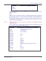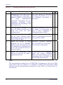
1
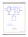
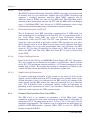
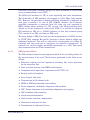
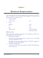
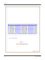
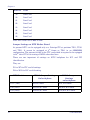
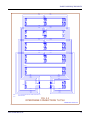
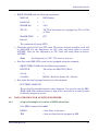
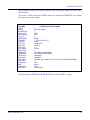
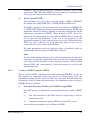
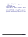
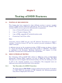
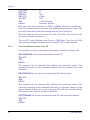
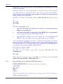
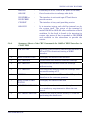
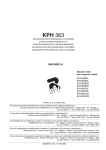
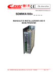
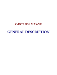
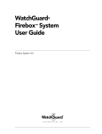
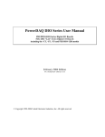
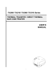
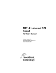
C-DOT DSS MAX
ISDN USER MANUAL
Section No. 400-027-0777
System
Practices
Draft 01, August 2000
C-DOT DSS MAX
ISDN USER MANUAL
© 2000, C-DOT
Printed in India
C-DOT DSS MAX
ISDN USER MANUAL
DRAFT 01
AUGUST 2000
BHADRA 2057
SERIES 000 : OVERVIEW
CSP SECTION NO. 400-027-0777
THIS C–DOT SYSTEM PRACTICE REFERS TO THE C–DOT DIGITAL SWITCHING SYSTEM
MAIN AUTOMATIC EXCHANGE (ABBREVIATED AS C–DOT DSS MAX IN THE REST OF THIS
PUBLICATION).
THE INFORMATION IN THIS SYSTEM PRACTICE IS FOR INFORMATION PURPOSES AND IS
SUBJECT TO CHANGE WITHOUT NOTICE.
A COMMENT FORM HAS BEEN INCLUDED AT THE END OF THIS PUBLICATION FOR
READER'S COMMENTS. IF THE FORM HAS BEEN USED, COMMENTS MAY BE
ADDRESSED TO THE DIRECTOR (SYSTEMS ), CENTRE FOR DEVELOPMENT OF
TELEMATICS, 39, MAIN PUSA ROAD, NEW DELHI - 110 005
© 2000 BY C–DOT, NEW DELHI.
Table of Contents
Chapter 1.
Introduction ..............................................................................................................................5
Chapter 2.
ISTU Architecture ....................................................................................................................6
2.1. Integrated services digital network (ISDN)....................................................................6
Chapter 3.
Hardware Requirements........................................................................................................13
Chapter 4.
Equipage of ISTU ...................................................................................................................20
4.1. Procedure of equipage ....................................................................................................20
4.2. Data Creation for an ISDN Subscriber .........................................................................21
Chapter 5.
Testing of ISDN Features ......................................................................................................27
5.1. Testing of ISDN Services ...............................................................................................27
5.2. ISDN U-Interface Testing ..............................................................................................27
5.3. ISDN Bearer Services ....................................................................................................32
5.4. ISDN Supplementary Services ......................................................................................35
5.5. Video conferencing and file transfer using vcon software ...........................................40
Annexure –I
Details of test sets for ISDN terminals .................................................................................44
Annexure - II
Operation Procedures for Supplementary Services in C-DOT ............................................46
H:\HOME\MAX\WORD\APISDNAR.doc
September 26, 2001
Chapter 1.
Introduction
This document describes about architecture and implementation of the Integrated
Services Digital Network capability in C-DOT DSS MAX. This capability in existing
exchanges can be implemented by replacing any one Terminal Unit by Integrated
Services Terminal Unit (ISTU). At present this unit can be equipped only at the
Principal Terminal Unit position of TI-01, 05 or 09. It cannot have any
concentration.
The ISTU just like any other TU communicates via the ICC (ISDN concentration.
Controller card) with the Time Switch Controller (TSC). This approach makes it
easier to the provisioning of ISTU without disturbing exchange operations.
Chapter 2 explains briefly the architecture of ISDN ‘Terminal Unit’ and various
cards being used in C-DOT DSS.
Chapter 3 describes the hardware requirements and interconnections and chapter 4
describes the procedures for equipping of ISTU and the necessary data creation.
Testing of various ISDN features is explained in Chapter 5.
ISDN USER MANUAL
5
Chapter 2.
ISTU Architecture
2.1.
INTEGRATED SERVICES DIGITAL NETWORK (ISDN)
The ISDN-traffic is of two distinct types i)
Circuit switched voice & data
ii)
Packet switched data.
In case of Circuit switched voice & data, the traffic is routed through ISDN/PSTN
network. In case of packet switched data, the packet traffic is routed/circuit
switched to PSPDN where packet processing takes place. This is a economical
solution and meant for quick implementation and deployment of ISDN-Service
C-DOT has implemented ETSI - PHI 300 099 interface to PSPDN - Network (INET) which is being expanded as overlay network, across the country to offer wide range of data communication services including 64/128 kbps frame relay service.
Both the cases of routing the packet data traffic on Bd and Bb channels, are
supported in C-DOT DSS.
2.1.1.
Architecture of ISDN Terminal Unit (Figure 2.1)
In C-DOT DSS architecture, the ISDN interfaces are terminated on a new
add-on terminal unit as ISTU. A max. of 256 bearer channels are provided by
integrating one ISTU which can be configured to support any combination of
BRI or PRI - interfaces. If the requirement of PRI/BRI interfaces are more
than 256 bearer channels, one or more ISTUs can be integrated in C-DOT
DSS with the option of equipping them in the same BM or distributed across
different BMs in the exchange.
The architecture also supports different level of concentration ensuring the
connectivity of every subscriber for signalling and providing uniform
allocation of time slots for switching of Bearer channels, carrying data and
voice.
The circuit switched traffic is separated at ISTU and routed towards CS
(Time Switch Unit of C-DOT DSS). Similarly packet switched traffic is routed
towards PSPDN on ETSI-PHI interface.
6
C-DOT DSS MAX
ISTU ARCHITECTURE
LCØ
8 PCM LINKS,
EACH OF 32 B-CHANNELS.
LC1
*
2Nos. 128 B-Ch., 8Mbps PCM LINKS
AS LINKØ AND LINK1
256x256
ITCØ
ICCØ
CS
ICC1
PS
256 Kbps
HDLC
ITC1
LC14
1 Mbps SERIAL LINK
FOR D-CHANNEL
LC15
PS : PACKET SWITCH
CS : CIRCUIT SWITCH
PCM
SIGNALLING
*
: 32 B-Ch. ONLY IN CASE OF CONCENTRATION
FIG. 2.1
ISTU ARCHITECTURE
\DESIGN\ISTU-AP\IST-ARCH
ISDN USER MANUAL
7
Chapter 2.
As explained earlier, the core switching element of C-DOT DSS i.e. 'T’ or 'T-ST’ functions as 'CS’ element for ISDN-traffic.
Basic Rate Interface (BRI) is through a twisted pair of copper cable
conforming to G.961 standard. It provides support for continuous powering
up of NT and in emergency condition, to support one TE for POTS service
with current limiting. The Primary Rate Interface (PRI) is standard 2.048
Mbps link, driven on symmetric twisted pairs with characteristic impedance
of 120 ohms, conforming to CCITT I.431 standard.
The ISDN terminal cards are Basic Rate Line (BRL) and Primary Rate Line
(PRL) cards.
2.1.2.
Basic Rate Line (BRL) Card (Figure 2.2)
The Basic Rate Line card (BRL) is an interface to the switching system
supporting '8’ U-interfaces towards the user. It interfaces with the ISDN
Terminal Controller (ITC)/Switching Network for signalling and switching of
voice and packet information.
The functions of the BRL card include HYBRID for 2 to 4 conversion and echo
cancellation, monitoring of line status, its activation and deactivation, over
voltage protection (to protect the exchange and the BRL card from high
voltages), test access (for testing the line side and exchange side of the Uinterface), power feeding (emergency or sealing current feeding) and 2B1Q
coding for U-interface. The B and D channels are separated and 2 B-channels
of each interface (total 16 B channels of each BRL-Card) are multiplexed on
2.048 Mbps link, similar to TG of ATU/DTU. The D channel signalling and
packet information is sent on shared signalling link (1.024 Mbps HDLC) to
the ITC. The BRL card can be equipped in any one of the 16 slots, assigned
for ISDN termination cards in the ISTU.
2.1.2.1.
U-interface Transceiver Sections
The U-interface is terminated on this block. A test access relay is used to
isolate line side and exchange side of the U-interface for testing purpose.
Emergency power or sealing current is fed to the NTs over U-interface. The
U-Interface Device (UID) along with associated circuitry like transformer,
protection device etc., sends and receives 2 B+D channels on user (NT)
interface. The U line interface also meets ANSI recommendation for return
loss and longitudinal balance, the timeslot of each subscriber for send and
receive of 2 B+D channel information towards the ITC. The 2 B channels and
D channel of each subscriber is separated by the UID. The B channels of 8
subscribers are multiplexed over 2.048 Mbps B channel bus towards ITC. The
separated D channel information is sent to ISDN D Channel Exchange
Controller (IDEC). Monitoring of the U line status and programming of the
UID is done by the onboard micro processor.
8
C-DOT DSS MAX
ISTU ARCHITECTURE
2Mbps PCM LINKS FOR 32 B-Ch.
2B+D
U-INT
D-Ch.
2B+D
D-Ch. (P+S)
LAPD
SIG. CTRL.
1 Mbps SERIAL LINK
LCP
LCP : LINE CARD PROCESSOR
P+S : PACKETS AND SIGNALLING
LAPD : LINK ACCESS PROTOCOL ON D CHANNEL
FIG. 2.2
BRI LINE CARD
\DESIGN\ISTU-AP\IST-BLC
ISDN USER MANUAL
9
Chapter 2.
2.1.2.2.
IDEC Section
The ISDN D channel Exchange Controller (IDEC) transmits and receives the
D channel data of each subscriber, handles the basic HDLC functions and
supports a standard processor interface. Each IDEC supports four D
channels, hence 2 IDECs are used on each BRL-card. The Signalling and D
channel packet information between the ITC and the BRL card is exchanged
over a 1.024 Mbps HDLC link, shared by 16 ISDN termination cards, using
collision detection through priority mechanism to resolve collision.
2.1.2.3.
B-channel Interface to ITC/SN
The 32 B channels of 16 BRI subscribers, terminated on '2’ BRL-cards, are
time multiplexed to 2.048 Mbps serial link (TG). For 16 termination cards, 8
nos. 2.048 Mbps serial links are used to carry B-channels between
termination cards and ITC-card. The ITC card generates one card select
signal for each card which is also fed to all the UIDs and they use it to place
the B channels data on 2.048 Mbps bus and extract the B channels data from
the 2.048 Mbps bus as per the programmed time slots. Between two BRL
cards of a TG, the first 16 timeslots are allotted to 1st BRL and last 16 time
slots to 2nd BRL card. The 2.048 MHz clock from ITC is used as the B Clock
by the UIDs.
2.1.2.4.
Power Feeding Section
Power is fed to the NTs by an ONBOARD Power Supply (DC -DC Converter).
The -48 V supply received from the back plane is converted to -96±3V and fed
to the NTs. The maximum current needed by a NT during emergency for the
longest loop is 25mA. The current fed (sealing or emergency) is limited by the
current limiting circuit provided by the thermistors on the card.
2.1.2.5.
Duplication & Protection
To ensure continuous operation of the system in the event of fault all the
signals are fed to BRL card from 2 ITCs working in hot-standby mode. If one
of them develops a fault, it is indicated to the BRL card by the change of the
status signal and the BRL selects the other copy through its 2 to 1 selection
logic. The U-Interface card is protected against surges and lightning by
providing transit protection on each U line interface. Additionally clamping
diodes are used to protect the UIDs against surges.
2.1.3.
Primary Rate Interface Line Card (PRL)
The PRL Card is an interface to terminate a 2.048 Mbps link, using
symmetric twisted pair cable with characteristic impedance of 120 Ohms. It
conforms to ITU-T recommendations I.431, I.604, G.703, G.704 and G.706 for
functional requirements. The interface can be configured for applications as
(30B+D) ISDN-PRI-Interface towards ISDN PBX as well as ETSI-PHI
Interface towards PSPDN.
10
C-DOT DSS MAX
ISTU ARCHITECTURE
Each PRL card forms a terminal group (TG) and a maximum of 8 PRL cards
can be accommodated in each ISTU.
The PRL-Card interfaces to ITC to route signalling and voice information.
The B-channels of PRI-interface are mapped on 2.048 Mbps link towards
ITC. However, the procedure to handle signalling information is different for
each type of interface. In case of PRI (30B+D) interface, the D-channel
signalling information is extracted from 16th time slot and converted to
HDLC format before sending it to ITC card on 1.024 Mbps signalling link,
shared by all the termination cards of the ISTU. It is possible to configure
PRI interface as PRI-16 i.e. (16B+D) interface so that each terminal group
(TG) consists of one PRL card and one BRL card.
The basic design of PRL-Card and also the implementation of ISDN services
in C-DOT DSS, supports H0 and H1 channels in future without adding any
additional hardware. This will be achieved by concatenating of 64 Kbps BChannels and they need not be contiguous, but should be progressive. Hchannels are used for higher bandwidth requirement e.g. LAN, high speed
data communication and Video transmission.
2.1.3.1.
PRI Interface Block
The PRI interface forms the most important block of the card doing almost all
the main functions of the card. The functions performed by this block are as
follows :
♦ Electrical coupling and line impedance matching, line access protection
for the subscriber line.
♦ Data and clock recovery from HDB3 coded signals.
♦ Compliance with input jitter requirements of CCITT I.431.
♦ Remote and local loopback
♦ Loss of signal indication
♦ Transmission of idle channel code.
♦ HDB3 to NRZ data decoding and encoding.
♦ Frame alignment, multiframe alignment and synthesis.
♦ CRC, Frame alignment and multiframe alignment error logging.
♦ CRC4 checking and generation.
♦ Alarm extraction/insertion.
♦ Clock wander and jitter compensation.
♦ Detection of unframed all ones.
♦ Transmission of unframed all ones.
ISDN USER MANUAL
11
Chapter 2.
This block is implemented using four major functional blocks namely
transmitter line interface, receiver line interface, the transceiver and twoframe deep elastic buffer. Elastic buffer is able to provide automatic buffer
recentering on occurrence of slip due to buffer full/empty while controlling
jitter and clock wander.
2.1.3.2.
D-Channel Protocol Handling
The D channel data is available in the 16th timeslot. This block extracts the
information of 16th timeslot and performs basic HDLC functions using HDLC
controllers. The processed information is forwarded towards ITC. Main
functions of this block are : Flag detection/generation, Zero delete/insertion,
Check for abort, Check for idle, Maximum frame length checking, CRC
generation and support collision detection for the sharing of 1.024 Mbps
signalling link.
2.1.4.
ISTU Control Unit
The control unit interfaces BRL and PRL cards on one end and TSU on the
other end. It has a 256 x 256 switch. The 256 channels are switched on to a
128 channel, 8Mbps link towards Time Switch Unit.
The D channel data traffic is switched towards ISTU where ETS1-PHI
interface has been configured. Signalling data received from BRL/PRL cards,
is forwarded to BP after LAPD to C.85 conversion.
The traffic on BP from an ISDN subscriber can be potentially 8-times the
traffic of a non-ISDN subscriber. To reduce the load on BP, some of the
functions like ISTP (terminal process), overload and concentration control are
shifted to the control unit of ISTU.
The active/standby status of control units is communicated to terminal cards
through the status information. The control units themselves update the
dynamic events at OS/application level so that switchovers are handled
properly.
12
C-DOT DSS MAX
Chapter 3.
Hardware Requirements
This section deals with the hardware requirements for installation of an ISTU in
terms of motherboard, cards and cables. Before equipping it is ensured that the
following items are available at the site.
1.
Motherboard ISTU
with card frame
2.
-
1 No.
PSU-A05
-
2 Nos
ITC
-
2 Nos
ICC
-
2 Nos
ISDN line cards
-
As per requirement
(Details given below)
Cards
ISDN Line Cards
There are two types of terminal cards which can be equipped in an ISTU in any
combination based on the requirement.
a)
BRI (Basic Rate Interface)
The valid slots for BRI cards are from 5 to 12 and 19 to 26 i.e. total 16 BRI
cards can be equipped in an ISTU.
Each BRL card has got 16 Bearer channels (B Channels) supporting 8
subscribers each with (2B+D) channels.
b)
PRI (Primary Rate Interface)
A maximum of 8 PRL cards can be equipped in an ISTU. Each PRI supports
(30 B + D) channels.
ISDN USER MANUAL
13
Chapter 3.
1
P
S
U
2
3
P
S
U
4
5
6
7
L L L
C C C
8
9 10 11 12 13 14 15 16 17 18 19 20 21 22 23 24 25 26
L L
C C
L L
C C
L
C
I I
T C
C C
Ø Ø
I I
C T
C C
1 1
L L L
C C C
L L
C C
L L
C C
L
C
NOTE : LC CAN BE BRL OR PRL
FIG. 3.1
ISTU CARD EQUIPAGE
\DESIGN\ISTU-AP\IST-FM
14
C-DOT DSS MAX
HARDWARE REQUIREMENTS
The valid slots are from 5 to 12 and 19 to 26. Each PRI card occupies two
consecutive slots. PRL card can also be equipped as PRI-16 for supporting
(15B+D) interface. In PRI-16 interface all the 16 cards can be equipped, the
valid slots are 3 to 12 and 19 to 26. Any combination of PRI (30B+D) & PRI
(15B+D) is feasible.
3.
Cables
No extra cables are required for ISTU to TSU connectivity. Existing flat
cables used for ATU/DTU/TSU connectivity can be used.
4.
Filter Boxes
Filter boxes 4 Amp, 2 mH – 4 Nos.
Slot No.
Card
1.
PSU-II – Copy 0
2.
-
3.
PSU-II – copy 1
4.
-
5.
Line Card
6.
Line Card
7.
Line Card
8.
Line Card
9.
Line Card
10.
Line Card
11.
Line Card
12.
Line Card
13.
ITC (ISDN Terminal Controller Copy 0)
14.
ICC (ISDN Concentration Controller Copy 0)
15.
-
16.
-
17.
ICC (ISDN Concentration Controller Copy 1)
18.
ITC (ISDN Terminal Controller Copy 1)
ISDN USER MANUAL
15
Chapter 3.
Slot No.
Card
19.
Line Card
20.
Line Card
21.
Line Card
22.
Line Card
23.
Line Card
24.
Line Card
25.
Line Card
26.
Line Card
Note: Line Card Can be BRL or PRL
Jumper Settings on ISTU Mother Board
At present ISTU can be equipped only as a Principal TU at positions TU11, TU21
and TU31. It cannot be equipped at 4th frame as TU41 in an SBM/MBM
configuration. The reasons for this is the TTC card which is required to be equipped
in 24th slot of TU41 for testing of ISDN subscriber lines.
There are two important id settings on ISTU backplane for ICC and ITC
identification.
They are
W1 to W7 for ITC card id settings
W9 to W15 for ICC card id setting.
ISTU Position as
ITC id Jumper Settings
On back plane
ICC id Jumper
Settings
on back plane
TU11 (TI01)
W5,W7 short
W14, W15 short
TU21 (TI05)
W3,W5,W7 short
W9,W14,W15 short
TU31 (TI09)
W4,W5,W7 short
W10,W14,W15 short
16
C-DOT DSS MAX
HARDWARE REQUIREMENTS
W1
•
•
W9
•
W2
• •
W10
• •
W3
• •
W11
• •
W4
• •
W12
• •
W5
• •
W13
• •
W6
• •
W14
• •
W7
• •
W15
• •
(ITC)
•
(ICC)
ISTU Power Supply Connections
Refer Fig 3.2 for Power Connection Details
ISTU – BM Interconnection
The connections of ISTU frame to the Time Switch Unit (TSU) frame are same as
that of any analog TU cables from each copy of ICC will be connected to the TSI
card of TSU on the backplane. The connections are shown in Fig. 3.3.
Cables
TSU to ISTU connections are given below. Example is being taken as ISTU to be
equipped in 2nd frame of a BM.
CABLE
ISTU Side
Slot/Conn./Tab.
TSU Side
Slot/Conn./Tab.
TT06
14/B/1
10/A/3
TT07
17/B/1
10/A/4
TT08
14/B/2
17/A/3
TT09
17/B/2
17/A/4
ISDN USER MANUAL
17
18
BLUE
BLACK
FB3
FB2
RED
0V
RING
-48V
RING
0V_1
-48V_1
-48V
DIG. GND
GND
FIG. 3.2
ISTU POWER CONNECTIONS
ISTU
FROM OVER HEAD TROUGH
C1
PSU2
3
C0
SPEECH
0V
SPEECH
-48V
0V_0
-48V_0
1
PSU1
-48V
DIG. GND
GND
RED
\DESIGN\ISTU-AP\IST-CFB
FB1
FB0
BLACK
BLUE
Chapter 3.
C-DOT DSS MAX
HARDWARE REQUIREMENTS
TT04
TT03
TT02
TT01
A
A
A
B
B
B
B
B
26
14
13
2
1
A
A
B
B
2
1
A
A
TU1
TT08
TT07
TT06
TT05
A
B
17
26
ISTU
14
TT12
TT10
TT09
TT11
A
B
B
B
B
B
26
14
13
2
1
A
A
TU3
TT16
TT14
TT15
TT13
A
B
B
B
B
B
26
14
13
2
1
A
A
B
B
B
26
2
1
A
A
B
B
2
1
TU4
BPU
A
TT03
TT04
TT07
TT08
TT01
TT02
TT05
TT06
A
TSU
B
17
26
TT11
TT12
TT15
TT16
NOTE -
10
TT09
TT10
TT13
TT14
1. TU-TSU INTERCONNECTIONS ARE SAME FOR DIFFERENT TU
CONFIGURATIONS.
FIG. 3.3
INTERFRAME CONNECTIONS TU-TSU
\DESIGN\ISTU-AP\IST-ICTU
ISDN USER MANUAL
19
Chapter 4.
Equipage of ISTU
4.1.
PROCEDURE OF EQUIPAGE
If an ISTU frame is being added, connect flat cables from ISTU to TSU. If it is
already fitted in a BM then this is not required. Switch on the power supply cards
after jacking them in. Ensure power supply cards are working ok. Jack in ITC and
ICC cards (both copy0 and copy1)
•
To equip ISTU in an MBM Exchange in a principal TU position the following
procedure is followed.
•
In a working switch if all PTU (Principal TU) positions are already equipped,
unequip a non-ISTU type TU (ATU-DTU) from the BM.
•
Follow the standard procedure for deleting routes/subs, TGP cards etc. and
unequip the frame.
Use the command. UNEQ-FRAME with following parameters.
MOD-NO
=
BM Number
RACK-NO
=
1
FRAME-NO
=
1/2/3
With this, the status of the frame becomes unequipped.
(In case of a new BM having ISTU frame a PTU position, in the above step
may be skipped.)
•
Insert ISTU frame in place of the ATU/DTU removed.
•
Complete all physical connections of ISTU.
•
Replace 3mH 2A-filter boxes on the busbar with 4A, 2mH and connect the power
supply.
In case of new BM with ISTU frame, this replacement is not required.
•
20
EQUIP the ISTU frame using the following command.
C-DOT DSS MAX
EQUIPAGE OF ISTU
•
EQUIP-FRAME with the following parameters.
MOD-NO
=
BM Number
RACK-NO
=
1
FRAME-NO
=
1/2/3
TIC-ID
=
TIC ID of the frame to be equipped e.g.Ti01 or Ti05
or Ti09
FRAME-TYPE
=
ITU
Execute
The command will equip ISTU
•
Check the status of ICC and TIC cards. The status of these controller cards will
be OOS-OPR. Do the diagnostics on ICC cards and bring them in service
ACT/SBY. Then do the diagnostics on TIC cards and bring them in-serviceACT/SBY.
Note:
•
For Diagnostics of ‘TIC’, ICC must be inservice.
Now line cards (BRL,PRL) cards can be equipped using the command
EQUIP-TRML-CARD with the following parameters.
•
HW-TYPE
:
The values are BRI, PRI, PRI-16
Ver-No.
:
1
Card-Slot
:
BM-No.- Rack No.-Frame No.- Slot-No.
Now make the trml equipped inservice by the command.
PUT-TRML-CARD-INS
The card will be brought inservice after diagnosis. You can also use the FRCTRML-ARD-INS command where by dgn of the card will not be done but will
be directly brought in-service.
4.2.
4.2.1
DATA CREATION FOR AN ISDN SUBSCRIBER
A typical example of creation of ISDN subscriber.
Give MMC command ‘cre-sub’.
DIRNO.
:
a free dirno. to be given
TEN
:
a free ten from the slot equipped as BRI
ISDN USER MANUAL
21
Chapter 4.
[LIN-TYPE]
:
PTM
[INS-TYP]
:
DIGITAL
[SUB-PRI]
:
[CALL-MOD]
:
[ORG-REG]
:
[TRM-REG]
:
[MTR-CLS]
:
[DET-BLG]
:
[ACC-BARR]
:
[LIN-CAT]
:
[SUB-CTG]
:
[CAB-ID]
:
[OPR-ACC]
:
[BS]
:
[B-SELECT]
:
[CHNL-BS]
:
2 – All - BS
[CALL-BS]
:
2 – All - BS
[ACS-OPT]
:
TONE-ANNC
BS123
EXECUTE
*
BS12 -
For speech and audio
BS3
For data
-
BS123
-
For speech, audio and data
The parameter left blank may be given default value or a valid parameter to
provide a certain facility to subscriber.
4.2.2.
Creation of Hunt Group for PRI subscriber
A hunt group is represented by one Principal Directory Number (PDN). All
its members may be already created directory numbers as member directory
numbers or free TENs as member-TENs or a combination of both.
Similarly, a DDI group is represented by its PDDI - Number and all its
members as free directory numbers. The TENs of DDI group are used as pool
22
C-DOT DSS MAX
EQUIPAGE OF ISTU
of resources to carry the traffic between Local Exchange and ISPBX for DDI Subscribers.
To create a Hunt Group for ISPBX issue the command CRE-HGP and obtain
the parameter entry form:
CRE-HGP
[PDN]
[PDDI]
[NUM-DGTS]
[HNT-TYP]
[METER-NO]
[Q-LGT]
[MEM-DIRN]
[TEN-BW]
[TEN-IC]
[LIN-TYP]
[INS-TYP]
[SUB-PRI]
[CAL-MOD]
[SUB-CTG]
[ORG-REG]
[TRM-REG]
[MTR-CLS]
[DET-BLG]
[ACC-BAR]
[LIN-CAT]
[OPR-ACC]
[BS]
[B-SELECT]
[ACS-OPT]
:
:
:
:
:
:
:
:
:
:
:
:
:
:
:
:
:
:
:
:
:
:
:
:
CREATION OF HUNT GROUP
< >
Any Free DIRNO
1
SEQ
MET
0
NONE
st
1 ‘TEN’ of PRI SLOT
NONE
ISPBX-PTP
DIGITAL
< >
NO-INT
1
NO-ORG (AS REQUIRED)
NO-TRM (AS REQUIRED)
NRM-MTR
ORD-BLG
INCMNG_NOT_BAR-OG_UPTO_LCL-ALL_BS (AS REQUIRED)
1
YES
BS123
SEQ
TONE-ANNC
The parameters PDDI and NUM-DGTS are used for DDI – group.
ISDN USER MANUAL
23
Chapter 4.
After obtaining the parameter entry form, the different parameters can be
defined as per their functions, explained below:
i)
Principal Directory Number (PDN) :
A free directory number is assigned to this parameter. When dialled to
PDN, the call is terminated on any one of the free circuit (Member
TEN or Member Directory Number) which is selected using
progressive hunting procedure. However, when the call is made to
member directory number, it is directly terminated on the dialled
number if it is free. In case of dialled number is busy/faulty or access
barred, the call fails.
Note: Not required for ‘PRI’ Hunt Group.
ii)
Hunting Type (HNT-TYP):
Only one type of hunting procedure as "Progressive" is implemented.
As such, this parameter has default value and need not be modified.
iii)
Queuing Length (Q-LGT):
This parameter decides the maximum number of calls that can wait in
queue if dialled through PDN and all the circuits are already busy. The
maximum value of this parameter is 200.
iv)
Member Directory Numbers (MEM-DIRN)
One or more directory numbers can be member of the hunt group. The
directory numbers should have been created and its status should be
OOS-OPR before they become member of the hunt group.
Note :
All the member directory numbers of a hunt group should be either
Analog Subscribers or ISDN-Subscribers. A mix of both the types in
single hunt group is not allowed. This is also true for member TENs,
defined as TEN-BW or TEN-IC. All the members of a hunt group
should be same type i.e. PSTN or ISDN.
v)
Member TENs (TEN-IC/TEN-BW):
The member TENs may be defined as incoming only or both way or
any combination of them. If one or more free TENs are defined as
member TENs using parameter TEN-IC, these TENs are not used to
terminate the call on the user. In other words, the exchange can not
use these circuits to terminate the call. Only the calls are originated on
these circuits by the user. For all the calls being received from the
user, the common characteristics of the hunt group is used to route the
call.
24
C-DOT DSS MAX
EQUIPAGE OF ISTU
Similarly, one or more free TENs, defined as member TENs using
parameters TEN-BW, these TENs are used to receive or terminate the
call as per the characteristic of the hunt group.
vi)
Line Type (LIN-TYP) :
This parameter may have any one of the values as PBX or PBX-REV
for Analog lines and ISPBX-PTP or ISPBX-PTM for ISDN-lines.
For ISDN - interfaces, the parameter has to be defined as ISPBX-PTP
or ISPBX-PTM. When the hunt group in terminated on the ISPBX, the
parameter should be defined, keeping in view the configuration of the
terminating interfaces on ISPBX. When defined as PTP, the call is
offered on a B-channel and the user (CPE or ISPBX) has to accept the
call on the selected B-channel. If the call is not accepted on the
specified B-channel, it fails with suitable cause value. When defined as
PTM, the call is offered on a B-channel with option to the user to
accept the call on any other free B-channel.
All other parameters may have default values or modified values as
explained previously as part of CRE-SUB command.
Note:
In case of the member directory nos., the characteristics of individual
subscriber is valid for originating calls and also for the terminating
calls when dialled through its own directory number. When dialled
through PDN, the characteristic of the hunt group are valid for the
terminating calls.
4.2.3.
Creation of DDI Group for ISPBX
This is valid for ISDN - interfaces and same command CRE-HGP is used for
this purpose as explained earlier for creation of Hunt Group. Only the
parameters having specific values for DDI are explained. For definition and
its possible values of remaining parameters, the explanation given in part of
CRE-HGP may be referred.
i)
Principle Directory Number of the DDI Group (PDDI)
Any DDI group is recognised by its principle directory number (PDDI)
for:
i)
The characteristics of the DDI users for originating as well as
terminating calls.
ii)
Cumulative metering against PDDI for all the DDI - users.
Any free directory number can be defined as PDDI.
ISDN USER MANUAL
25
Chapter 4.
ii)
Number of Digits (NUM-DGTS)
This parameter defines the number of DDI digits, to be sent towards
ISPBX to terminate the call on the DDI-user, which is also an
extension of ISPBX.
iii)
Directory Number (DIRNO)
The directory number of the DDI users are allocated from the free list of
directory numbers. It is preferred that such directory nos. should be derived
in a block e.g. if 10,000 directory numbers are created on exchange code 548
and they are 548XXXX, the DDI users for one ISPBX may be reserved as
5481XXX to 5481YYY for XXX to YYY as DDI users. For example, 160 DDI
users may be created as 5481520 to 5481680. However, any block of free
directory numbers 548XXXX can be DDI users and depending on the value of
the parameter "NUM-DGTS", the last digits are sent to the ISPBX.
26
C-DOT DSS MAX
Chapter 5.
Testing of ISDN Features
5.1.
TESTING OF ISDN SERVICES
This chapter has been organised in three different sections to ensure complete
testing of ISDN services within the exchange as well as across the network. The
testing of ISDN services require the following add-on equipments.
1.
2 nos. of Network Terminator (NT)
2.
2 nos. of Terminal Adapter (TA)
3.
2 nos. of IBM compatible PC with add-on data cards
4.
Connecting U and S bus cables.
Note :
Connection between ISDN sub line and NT (Network Termination) is called U
interface. Connection between NT and the customer premises equipment (CPE) is
called S interface.
A reference test set up for acceptance testing of ISDN services is shown in figure
5.1. Create the Directory Numbers with service profile as “DIGITAL” subscribers,
as explained in the document “Exchange Operations” and chapter 4 of this
document. Now the tests on the interface can be performed.
5.2.
ISDN U-INTERFACE TESTING
The U-Interface (LT) in C-DOT DSS confirms to 2BIQ line coding and Embedded
Operational Channel (EOC) functions are part of 2BIQ line coding. The EOC
functions are used to support the functional testing on LT in the exchange as well
as NT in the customer premises up to S-Interface. The integrated tests are
sufficient to test and isolate the faults in the interface.
5.2.1.
Test Procedures for ISDN U-Interface
The CRP command TST-TRM is used to perform the tests on the U-interface
in C-DOT DSS. On execution of CRP command, the following parameter
entry sheet is displayed on the screen.
ISDN USER MANUAL
27
Chapter 5.
RTN-COD
RPT-FMT
REPEAT
TML-TYP
TST-SET
TEN
DIRNO.
:
:
:
:
:
:
:
G
B
NO
LINE
60X
Circuit Number
Directory Number
Only one of the two parameters as TEN or DIRNO, should be specified at a
time. The command can be executed after defining the parameter values. The
successful execution of the tests confirm that the line is fault free.
The valid value for the test sets are 607, 608, 609 & 610. The details of the
test sets are listed in Annexure - I.
Test set 607 covers Exchange side Tests on ISDN Line. Test Sets 608, 609
cover outside exchange functional tests, for which ‘TTC’ card is required.
5.2.2.
Activation/Deactivation from LT
It is possible to activate to deactivate the interface from the exchange side.
FRC-TRM-OOS (to deactivate the interface from LT)
TML-TYP
TEN
DIRNO
:
:
:
The command can be executed after defining the parameter values. The
successful execution of the command confirms that the interface has been
deactivate.
FRC-TRM-INS (to activate the interface from LT without tests)
TML-TYP
TEN
DIRNO
:
:
:
The command can be executed after defining the parameter values. The
successful execution of the command will result in activation attempt, being
initiated from LT. However, in case of fault of LT or NT, the interface will be
deactivated with its status, marked as OOS-SO.
PUT-TRM-INS (to activate the interface from LT after successful testing)
TML-TYP
TEN
DIRNO
28
:
:
:
C-DOT DSS MAX
TESTING OF ISDN FEATURES
The command can be executed after defining the parameter values subject to
the condition that the TLC is already created. The successful execution of the
command confirms that there is no fault in LT. The line status is marked as
INS-FREE. In case of fault in DLL or NT, the interface will be deactivated
with its status, marked as OOS-SO.
5.2.3.
Procedure for Testing of ISDN Termination Card
In case, more than 50% interfaces corresponding to a Interface Card is
reported as faulty, it is advised to perform the tests on the BRL card. The
card can be tested using CRP command TST-TRML-CARD with parameters
as :
RTN-COD
RPT-FMT
REPEAT
TML-CRD-TYP
TST-SET
CARD-SLOT
:
:
:
:
:
:
G
B
NO
BRI
605 or 606
The status of the BRL card can be displayed by using CRP command DISPLTRML-CARD-STATUS with parameter as :
TML-CRD-TYP
CARD-SLT
:
:
BRI
The status of the card can be displayed as INS-NRM, INS-FRC or OOS-SE.
INS-NRM
:
Card has been brought INSERVICE
performing the complete tests, successfully.
after
INS-FRC
:
The card has been made INSERVICE, forcibly
without performing any tests.
OOS-SE
:
The card is faulty.
The status of a BRL card can be modified to “Out of Service” by using CRP
command FRC-TRML-CARD-OOS. Similarly, its status can be modified to
“In service” by using CRP command FRC-TRML-CARD-INS without testing
or PUT-TRML-CARD-INS after successful testing.
5.2.4.
Creating a Reference Test Circuits (TLC) in C-DOT DSS
The TLC is created to simulate the functions of LT when tests set 608 is
executed to verify the functioning of NT up to S-Interface. Similarly, it
simulates the functions of NT to test the LT in the exchange. This helps in
integration of all the functional requirements of testing of ISDN-Interface in
C-DOT DSS as the tests are simulated in conformance to actual functional
ISDN USER MANUAL
29
Chapter 5.
requirement. This avoids the use of any additional test equipment to isolate
and locate the fault.
Sufficient checks are also incorporated to verify the sanity of TLC, time to
time. This possible by testing the TLC at the time of creation itself. The TLC
is functionally tested in totality before making it available for testing of other
ISDN-interfaces in C-DOT DSS.
The TLC is created by using CRP command CRE-TST-CKT with parameters
as :
TLC-TEN
TST-TEN
:
:
The basic requirements are :
1.
The TLC-TEN should be the first free circuit (i.e. not associated with
DIRNO) of any BRL card.
2.
The status of the BRL card should be INS-NRM. This can be ensured
by executing the command TST-TRML-CARD
3.
The TST-TEN should be any free circuit (i.e. not associated with
DIRNO) of the same BRL card or any other BRL card in the ISTU.
After executing the command, the TLC is created and subjected to functional
tests by using the TST-TEN as reference circuit. Once the functional tests are
executed and passed, the status of the circuit is marked as INS-FREE which
be verified using command DISPL-TRM-STATUS.
Procedure to Delete a TLC
The TLC can be deleted using CRP command DEL-TST-CKT with
parameters as :
TLC-TEN
:
Note : Before deleting the test circuit, BRL card should be made OOS-OPR
using CRP command FRC-TRM-CARD-OOS.
5.2.5.
How to Observe the Status of ISDN-Interface ?
DISPL-TRM-STATUS (to monitor the status of interface)
STAT-TRM
TML-TYP
TEN
DIRNO
:
:
:
:
On execution of the above command, the current status of the U-interface is
displayed which may be as:
30
C-DOT DSS MAX
TESTING OF ISDN FEATURES
5.2.6.
OOS-SO
:
Fault may be in LT, DLL or NT (fault is out side)
OOS-SE
:
Out of service due to exchange side fault.
INS-FREE or
INSF-FREE
:
The interface is activated upto NT and free to
provide service.
CP-BUSY
:
The interface is busy and providing service.
OOS-SUS
:
It is transient status and valid for internal use by
the system itself. The status of the terminal is
made OOS-SE or OOS-SO after verification of fault
condition. It the fault is found to be transient in
nature, the status of line is marked as INS-FREE
and available to the subscribers to provide the
service.
Summary Sheet of the CRP Commands for O&M of ISDN Interface in
C-DOT DSS
1.
CRE-TST-CKT
To create a test circuit to simulate the functions of
LT and NT for functional testing of ISDNinterface.
2.
DISPL-TRM-STATUS
To display the status of the interface
3.
FRC-TRM-OOS
To deactivate the interface from the exchange
4.
FRC-TRM-INS
To activate the interface from the exchange
without testing
5.
PUT-TRM-INS
To activate the interface from the exchange after
successful testing of LT
6.
TST-TRM
To test the interface as LT as well as NT up to SInterface at the customer premises
7.
DISPL-TRML-CARDSTATUS
To display the status of the card
8.
FRC-TRML-CARD-OOS
To make the card out of service for replacement or
as a mandatory requirement to delete the test
circuit.
9.
FRC-TRML-CARD-INS
To make the card in service forcibly i.e. with out
performing the detail tests
ISDN USER MANUAL
31
Chapter 5.
10.
PUT-TRML-CARD-INS
To make the card in service after performing the
detail tests on the card as well as all the 8 LTs.
11.
TST-TRML-CARD
To test the card
12.
DEL-TST-CKT
To delete the test circuit if it is faulty
5.3.
ISDN BEARER SERVICES
Using the setup as shown in figure 5.1, different calls are made to test ISDN to
ISDN, ISDN to PSTN and PSTN to ISDN interworking tests. The details of the
tests are given in the following table. The successful tests will ensure the
ISDN&PSTN interworking across the network. “Packet Mode” Bearer services need
not be tested as they are not available in C-DOT DSS at present but likely to be
available in immediate future.
Tests for Teleservices
S. No
1
2
3
Test Description
ISDN to ISDN Call
(i)
Basic ISDN to ISDN local Call
(ii)
ISDN to ISDN Call through DECADIC routes
(iii)
ISDN to ISDN Call through MOD-R2 route
(iv)
ISDN to ISDN Call through CCS7 route
(i)
The calls are originated from two ISDN subscribers A1
& A2 on the same ISDN line and terminated on the
two ISDN subscribers B1 & B2 on another ISDN line.
(ii)
The calls are originated from two ISDN subscribers A1
& B1 on the different ISDN lines and terminated on
the two ISDN subscribers A2 & B2 on different ISDN
lines.
The calls should be successful
The calls should be successful
ISDN Calls with in the Interface
The call is offered to the second
ISDN phone on the same line
and connection is established
on answer.
Two Simultaneous ISDN Calls with same and different
Bearer Services.
The calls are originated from two ISDN subscribers
A1(SPEECH) & A2 (3.1 KHz) on the one ISDN line and
terminated on the two ISDN subscribers B1(SPEECH) & B2
(3.1KHz) on another ISDN line. (A1&B1 are PHILIPS ISDN
Phones and A2&B2 are TAs).
Note : ‘SPEECH’ means normal voice call, while ‘3.1 KHz,
Audio means a ‘FAX’ call.
32
The calls should be successful
Two Simultaneous ISDN Calls
The two ISDN phones are connected on the same interface
using multi-drop connector. The call is made from B by
dialling its own directory number.
4
Expected Result / Response
The calls should be successful
C-DOT DSS MAX
TESTING OF ISDN FEATURES
Tests for G3 FAX Services
S. No
1
Test Description
ISDN to ISDN using TA
The test set up is made by connecting two TAs on lines A &
B. The Analog Ports at TAs, are configured as FAX ports.
The call is made from FAX connected to A , by dialling the
number B .
2
The call should be successful
between two FAX machines
and the FAX transmission is
also through.
ISDN to Analog
The test set up is made by connecting TA on ISDN line A
and its Analog Port is configured as FAX port. A FAX
machine is connected to TA of ISDN line A and another
FAX machine is connected to Analog Line C. The call is
made from FAX connected to A , by dialling the number C .
3
Expected Result/Response
The call should be successful
and the FAX transmission is
also through.
Analog to ISDN
The test set up is made as explained in Step-2. The call is
made from FAX connected to C, by dialling the number of
ISDN line A.
The call should be successful
and the FAX transmission is
also through.
Tests for Misc. Services
S. No.
1
Test Description
Expected Result / Response
ISDN Call to Level 1 Services
Level 1 positions , 198 as non metered services and 131 as
metered services are already created in the Exchange.
A call is made from ISDN Phone A to 198.
A call is made from ISDN Phone A to 131.
The call is put through
successfully without
incrementing meters.
The call is put through
successfully, incrementing the
meter of A.
Tests for Bearer Services
S.No.
1
Test Description
Expected Result / Response
File Transfer Using PC ( 64 Kbps UDI data call )
The test set up is made by connecting two TAs on ISDN
lines A & B. The TAs are configured as Synchronous DTEs.
The PCs are connected at the asynchronous data ports .The
call is made from A by dialling the number B, from the
keypad.
ISDN USER MANUAL
The call is put through
successfully
with
bearer
service as “ 64 Kbps UDI “ and
the file is transferred from
terminal A to B.
33
Chapter 5.
H:\home\max\word\isdnbr02.jpg
Fig. 5-1
ISDN TEST SETUP
34
C-DOT DSS MAX
TESTING OF ISDN FEATURES
5.4.
ISDN SUPPLEMENTARY SERVICES
In C-DOT DSS, all the PSTN feature available for analog subscribers, are also
available to ISDN subscribers except multi-party services. For details of
supplementary services, refer Annexure-II of this document. The ISDN specific
supplementary services are tested as per the procedure, explained subsequently in
this section.
Even though the supplementary services DDI and SUB addressing are supported in
C-DOT DSS and validated by TEC for its functioning, it is not feasible to test at site
due to unavailability of suitable test equipments. The supplementary services
as CD, UUS, CUG, CONF and 3 PTY are not supported in C-DOT DSS at
present.
5.4.1.
Connected Line Identification Presentation (COLP) and Connected
Line Presentation Restriction (COLR).
This facility is used by the subscriber to know that who is the ultimate
destination, being connected against his dialled number. This is important in
case of diversion when the call is being diverted to some other number.
5.4.2.
i)
A has subscribed COLP
ii)
B has subscribed to diversion and diversion is activated with
destination directory number ‘C’.
iii)
A calls to B but the call land on C.
iv)
Now C answers the call and A gets the information on the LCD display
that the connected number in C and not the dialled number B.
Advice of Charge (AOC)
This facility is used to know the charge for the call as it is the case of 16 KHz
metering pulse in case of Analog line.
5.4.3.
i)
Subscribe the facility AOC-E on A.
ii)
Make a call from A to the network.
iii)
Release the call after successful conversation and verify the total
charge units being displayed on the LCD display.
iv)
Now subscribe AOC-D on A and repeat (ii) and (iii). The charge units
are periodically updated on the LCD display with periodicity defined
and controlled by a system parameter AOC-D timer.
Terminal Portability (TP)
This feature is used by the subscriber to suspend the call and resume it later
on.
i)
ISDN USER MANUAL
Subscribe the facility TP on A.
35
Chapter 5.
ii)
Make a call to B
iii)
Press “SUSPEND” on the ISDN terminal equipment.
iv)
The call is suspended. Now remove S-BUS and reconnect. Press
“Resume” and A is again connected to B.
5.4.4.
Multiple Subscriber Number (MSN)
5.4.4.1.
This service provides the facility of assigning multiple ISDN numbers to
more than one user on a single interface. This service allows direct dialling to
one of the terminals connected to an access and enables the network to
determine ISDN number which is applicable for originating calls for
subscriber characteristics and charging services. The addressing of terminals
is achieved by applying a set of ISDN numbers which need not be
consecutive. When a call with one of these ISDN numbers is delivered the
corresponding MSN number is indicated to the MSN user.
5.4.4.2.
Grant Multiple Subscriber Number (GRNT-MSN)
MSN is one of the most important facility extended to ISDN subscriber which
is very useful in Group or Business Environment. The resources of single
ISDN interface i.e. 2B channels can be shared by more than one user with
the advantage of its own directory number and service profile. For example, a
subscriber 5481500 is created as ISDN subscriber. It is possible to add 6
other directory numbers 5481501, 5481555 etc. with the advantages as listed
below:
♦ Each subscriber has its own directory number
♦ Each subscriber has its own service profile e.g. different access level for
O/G calls, a set of facilities etc.
♦ Each subscriber can have specific bearer service.
♦ Individual detail bill records for long distance calls as well as separate
meter readings for each subscriber are available.
To programme the MSN in C-DOT DSS, an ISDN subscriber is created with
MSN facility. If already created, the MSN facility can be assigned using
command MOD-SUB-FAC. The facility should be granted using CRP
command GRNT-MSN. The parameter MAPD-NO can be any coded sequence
of digits with the option of retaining subscribers' own directory number as
mapped number. Now one or more MSN subscribers can be added using
command ADD-MSN-DN. The command provides the flexibility to define the
service profile of the MSN subscribers with unique mapped number.
To grant MSN facility to a normal ISDN subscriber, input parameters for the
command GRNT-MSN are:
36
C-DOT DSS MAX
TESTING OF ISDN FEATURES
GRNT-MSN
GRANT MULTIPLE SUBSCRIBER NUMBER
DIRNO
:
MAPD-NO
:
On successful execution of the command, type of DIRNO is changed from
NRML to PMSN.
Note :
MSN service is activated only when the ISDN equipments being installed in
the subscriber premises, is also programmed properly. For programming of
PHILIPS ISDN phone and TA the user manual may be referred. However,
the flexibility of receiving the call in broadcast mode if desired, may or may
not exist in all the equipments.
5.4.4.3.
Addition/Creation of more Directory Numbers on an ISDN Interface
(ADD-MSN-DN)
This command will be used for adding MSN subscriber after MSN facility has
been granted (through GRNT-MSN command).
ADD-MSN-DN
ADDITION/CREATION OF MORE DIRECOTORY NUMBERS
PMSN
:
ISDN DIRNO WITH MSN FACILITY
MSN-DN
:
ANY FREE DIRNO
MAPD-NO
:
Same as MSN-DN
[SUB-PRI]
:
1
[CAL-MOD]
:
NO-INT
[OPR-ACC]
:
YES
[SUB-CTG]
:
1
[ORG-REG]
:
NO-ORG
[TRM-REG]
:
NO-TRM
[MTR-CLS]
:
NRM-MTR
[DET-BLG]
:
ORD-BLG
[ACC-BAR]
:
INCMNG_NOT_BAR-OG_UPTO_LCL-ALL_BS
[B-SELECT]
:
SEQ
[BS]
:
BS12
[CHNL-BS]
:
1-ALL_BS
[CALL-BS]
:
1-ALL_BS
ISDN USER MANUAL
37
Chapter 5.
5.4.4..4
Sl. No.
Testing procedure for MSN facility
Details of Test Description
Expected Response
1
Register the facility MSN with A
as TRM-REG and programme 5
additional MSNs as A1 to A5 for
A,
using
ADD-MSN-DN
commands. Programme the user
equipment accordingly. Verify
originating and terminating calls
for A & A1 to A5.
The calls should be successful,
indicating that MSNs A1 to A5
are configured successfully on
interface A.
2
Note down meter readings of A &
A1 to A5. Make calls from each of
them and verify the meter
readings again.
The meter readings for A & A1 to
A5 should be incremented for
each of them, conforming to
billing operations for MSN.
3
Modify the access barring as STD New access barring should be
for A5 using command MOD- effective, conforming to individual
SUB-CHAR and also register the service profile of MSN
facility SUB-OG-BAR.
4
Modify the facility to grant Successful diversion, conforms
diversion for A5 as DOB-SEL- that each MSN can subscriber a
NUM. Activate the diversion from set of services, individually.
A5 and verify it by dialling from A
to A5. The call should mature on
diverted number.
5
Modify the subscribed bearer It should fail as A5 in PHILIPS
services as BS3 for A5. Make a phone and request SPEECH
origination from A5.
which is not subscribed by A5 and
conforming that each MSN can
subscribe BS independently.
!
✕
Note:
The programming considerations in C-DOT DSS is transparent to the type of CPE,
being used by the user. However, it is different in CPEs. The functioning of MSN
depends upon the programming considerations of the CPE, to be derived from its
user manual.
38
C-DOT DSS MAX
TESTING OF ISDN FEATURES
5.4.5
Call Hold (CH-WR / CH-WOR)
The call hold service allows a user to place a existing call on ‘hold’ and
subsequently re-establish communication as and when desired. A B-Channel
may or may not be reserved after the call is ‘put on hold to allow the
origination or possible termination of other calls. The option of reserving or
not reserving a B-Channel when a call is ‘held’, is based on the type of
registration in the exchange.
Facility registration/activation/deactivation
The facility call hold-with reservation (CH-WR) or call hold-without
reservation (CH-WOR) is subscribed as REG-TRM. The existing call is put on
hold by pressing ‘Hold’ key on the ISDN CPE. A new call may be received if
in waiting or new call can be originated. The call, put on hold can be
retrieved by using ‘Hold’ key once again.
Setup Requirement
♦ A and B as ISDN subscriber
♦ C and D as PSTN subscriber
♦ CCS7 loopback route
Note:
The facility is tested with both the option as B-Channel reservation or
without reservation. Also the facility is tested by putting the originating as
well as terminating call on hold.
5.4.6
Sub Addressing
This feature is offered to the called user to expand its addressing capability
beyond that provided by the ISDN number i.e. the Directory Number. The
sub address is used by the served user to identify a particular terminal on a
multi-drop access or a virtual terminal or process within the terminal. At the
time of offering the call to the user, the sub-address, if received from the
calling party, is delivered to the user. It is the functionality of the user CPE
to interpret and act on the sub-address information.
Registration/Activation/Deactivation
The facility “SUB” should be registered as TRM-REG i.e. terminating facility.
There is no procedure for activation or deactivation as the facility is activated
by default on registration.
Setup Requirement
♦ ISDN subscribers A and B
♦ CCS7 loopback with route code = 02
ISDN USER MANUAL
39
Chapter 5.
Test Procedure:
As there is no terminal to allow interleaving of SUB address at the time of
originating the call, the facility is tested using protocol tester by originating a
call from Protocol tester and monitoring the SUB-Address information on the
called user interface. As per the definition of the service, the network has to
deliver the information without any processing or action which is the part of
functional requirement of CPE. The test procedure is sufficient to validate
the ‘SUB’ facility as far as Switching System is concerned.
5.4.7
Line Hunting for Hunt Group
Line Hunting is a supplementary service that distributes all the incoming to
a specific ISDN number, over a group of ISDN interfaces. When dialed
through the Group ISDN number, one of the free ISDN interface from group
of interfaces is identified to put through the call. However, if the ISDN
number of the individual interface in the group is directly dialed, the call is
terminated if the interface is free otherwise it fails. In other words, such calls
are offered as normal terminating calls.
Registration/Activation/Deactivation
The facility is automatically assigned to the ISDN number when it is created
as ‘Hunt Group’ with free ISDN interfaces without directory number and/or
ISDN subscribers as its group members. For all the incoming calls, the
common service profile of the group is effective when dialed through group
number. The same is valid for outgoing calls, if originated from the ISDN
interface without DIRNO. In case of individual subscriber which is also the
part of Hunt Group, its own characteristics remain effective when making
outgoing calls.
Commands:
CRE-HGP
SETUP
♦ A, B, C, D, E & F as ISDN subscriber
♦ CCS7, MOD-R2 and Decadic signalling loopbacks.
5.5.
VIDEO CONFERENCING
SOFTWARE
AND
FILE
TRANSFER
USING
VCON
Video conferencing through ISDN line can be done using VCON software and
VCON hardware kit provided by VCON International. Minimum requirements for
this package are
40
1.
Pentium PC with 200 MHz processor
2.
Windows 95 or 98 Loaded on the PC
C-DOT DSS MAX
TESTING OF ISDN FEATURES
5.5.1.
3.
32 MB RAM
4.
PCI Bus interface
VCON Kit Comprises of following items:i)
Cruiser 75/150 PCI card on which one ISDN line can be terminated.
OR
Cruiser 384 PCI card on which 3 lines can be terminated.
ii)
Analog desktop camera
iii)
Telephone hand set
iv)
ISDN interface cables
v)
Meeting Point setup CD-ROM.
Note :
For local testing, two VCON kits and two PCs will be required.
5.5.2.
Hardware Installation
♦ Insert PCI cruiser card in the free PCI slot at Motherboard of the PC.
♦ Connect ISDN Line pair to ‘NT’ and from NT to PCI card jack.
♦ Connect the Main Analog camera in the designated jack of PCI card.
♦ Connect the handset to PCI card for speech purpose.
♦ Switch on the PC to boot it.
5.5.3.
Installation of Meeting Point Software Package
♦ Note down Licence Number of Meeting Point S/W as written on the CDROM provided.
♦ Insert CD ROM in the CD Drive. In D drive, select Meeting Point
Installation Utility. From this window install MSDUN version 1.3
winsock 2 and Meeting Point 4.0.
♦ Once Meeting Point 4.0 is installed Welcome Window will open. Click
‘Next’ in this window.
♦ In ‘User Information’ window, fill the name & company (say ‘Nainital’ &
‘DOT’ respectively). In serial No. fill Licence No. as already noted from
CD-ROM. Click Next.
♦ In “Software Licence Agreement” window click NEXT.
♦ In “Setup Type” window, select Typical and then click next.
♦ In “Start Copying Files” window, click next.
ISDN USER MANUAL
41
Chapter 5.
♦ In “Setup complete” window, select yes and click next.
♦ In “configuration wizard – User Information” window, fill up all
informations and click next.
♦ In “configuration wizard – switch Type” window, select ‘INDIA’ and
Switch Type EURO-ISDN NET3. Then click next.
♦ In “configuration wizard – phone Number” window, fill up the Number of
ISDN Lines = 2 and fill up the Phone No. of ISDN Line in front of #1 as
well as #2. Then click next.
♦ In “configuration wizard – H323” window, fill all the informations as
default and select “Allow adaptive Bandwidth Adjustment” and
“Automatic buffering control” Then click next.
♦ In “configuration wizard – Multi VGA Support” window, select Disable
and click next.
♦ In “On-line Directories” window, select file “ISS.VCON.CO.ie (DVC
server)” and click next.
♦ In “configuration wizard – Dan/Zoom/Tilt camera” window, select camera
Type as others and Com port as Com1. Then click next.
♦ In “configuration wizard – MSN” window, select No and click next.
♦ In “sub-Addressing” window, click next.
♦ In “Confirmation window, click finish.
♦ This will install the Meeting Point Software completely.
♦ Shut down and reboot the P.C.
5.5.4.
Dialling Procedure
♦ Click start in windows taskbar. Go to programmes and select Meeting
Point.
♦ Switch on the Camera, mounted on Top of your PC cabinet.
♦ Local video image will appear on a window on the Monitor Screen. Adjust
the camera, to get sharp and focussed images.
♦ On user array, select “Dial” and dial the telephone No. of distant end
ISDN line (or 2nd ISDN Line for testing purpose, on which similar set up
is available). Now video images of called party will appear on the Monitor.
Thus video conference will began. One can speak to other end using
handset provided along with.
42
C-DOT DSS MAX
TESTING OF ISDN FEATURES
5.5.5.
Data Transfer Using ‘VCON’ Software
In user array, select Transfer. It will ask for the file name to be transferred.
Give the file name along with full directory path. Click OK. Data Transfer
will start. Speed of Data transfer time taken will be shown.
ISDN USER MANUAL
43
Annexure –I
Details of test sets for ISDN terminals
1.
TEST SET NO. = 605
1.
2.
Essential and non-essential power on tests on the BRI/PRI terminal cards.
TEST SET NO. = 606: Terminal inside exchange tests for BRL/PRI card
Test Set No. 606 Details
3.
I.
44
1.
B-Channel loop back test at LT end
2.
D Channel loop back test at LT end
3.
Line activation / deactivation test
4.
IDEC functionality test
5.
NT activation / deactivation test using TLC
6.
CRC generation recognition test using TLC
7.
TLC indication bit test or UID event detection test
8.
TLC line loop back test.
9.
Power-On test on the terminal card.
TEST SET NO. = 607 : inside exchange line side tests (BRI only) and inside
exchange TLC functional tests.
Inside Exchange Line Side Tests
1.
Constant current limiting circuit test.
2.
-48 Volt links constant current limiting ckt test.
3.
B channel loop back test at LT end
4.
D channel controller test
5.
D channel loop back test with LT.
C-DOT DSS MAX
DETAILS OF TEST SETS FOR ISDN TERMINALS
II.
4.
5.
6.
Inside Exchange TLC Functional Tests
1.
TLC-LIN-CKT activation and deactivation test.
2.
TLC CRC generation recognition test.
3.
TLC indication bits test
4.
TLC line loop back test
5.
PRI-SYN-FAIL Test
TEST SET NO. 608 : Terminal Outside Exchange Functional Tests.
1.
Line circuit activation and deactivation test.
2.
B1+B2 channel loopback with NT.
3.
2B+D channel loopback with NT.
4.
S/T interface activation and deactivation test.
5.
Non-destructive test, consists of
a)
Block error counter preset test.
b)
NT embedded operational channel capability test.
c)
NT/UID CRC error recognition logic test.
d)
LT/UID CRC error recognition logic test.
TEST SET NO. = 609 : Terminal Outside Exchange Electrical Tests.
1.
Interference (foreign potential) voltage, test
2.
Insulation resistance
3.
Insulation capacitance
TEST SET NO. = 610 : Inside and Outside Exchange Functional Tests. (Test
607 + 608+609)
ISDN USER MANUAL
45
Annexure - II
Operation Procedures for
Supplementary Services in C-DOT
A.1
Sl.
NUMBER IDENTIFICATION SUPPLEMENTARY SERVICES
Facility
No.
Registration
as TRM-FAC
Activation
Deactivation
Remarks
CLIP
NO
NO
In
case
of
PSTN
Subscriber, the telephone
instrument should support
CLI display.
NO
NO
1.
CLIP
2.
CLIR
3.
CLIRO
CLIP&CLIRO
NO
NO
4.
MCID
MCID
See Note-1
NO
Subscriber is put under
malicious
observation
using command MODSUB-OBS
with
OBSTYP=MALC
5.
MSN
MSN
NO
NO
Only for ISDN
6.
DDI
NO
NO
Only for ISDN . Applicable
to DDI groups , created
using command CRE-HGP.
7.
SUB
NO
NO
Only for ISDN. GRNTMSN to grant the facility
and ADD-MSN-DN to add
additional
MSN
Subscribers.
8.
COLP
NO
NO
Only for ISDN. Can be
used with C-DOT-TA210 as
PHILIPS Phone does not
support the feature. The
facility is available by
default
to
all
the
subscribers
and
no
registration is required.
9.
COLR
NO
NO
Only for ISDN
10.
COLRO
NO
NO
Only for ISDN
Note-1 :
46
Registration
as ORG-FAC
CLIR-PR
SUB
COLR-PR
COLRO
The PSTN subscriber can invoke the service just by HSF. A ISDN
subscriber can invoke the service by * 65 # after switching over to
C-DOT DSS MAX
OPERATION PROCEDURES FOR SUPPLEMENTARY SERVICES IN C-DOT
“Keypad Dialling Mode” from conversation stage. Procedure to switch
over to “Keypad Dialling “ is specific to the user’s equipment e.g for
PHILIPS Phone , the keys < Memory > <Display> are to be pressed .
The complete procedure for invocation of MCID service from PHILIPS
ISDN Phone is : <Memory> <Display> *65# . In the absence of any
procedure from TEC for ISDN Subscribers , the in built capability of
PHILIPs telephone has been exploited to support the feature.
A.2
Sl.
CALL OFFERING SUPPLEMENTARY SERVICE
Facility
Registration
as ORG-FAC
No.
Registration
as ORG-FAC
Activation
Deactivation
NO
NO
Remarks
11.
LH
12.
CFU(FXD)
ABSNT-FXDNUM
*28#
#29#
GNT-ABS-SRV
13.
CFU(SEL)
ABSNT-SELNUM
*14 B#
#15#
Subscriber
has
activate the facility
14.
CFB(GRP)
DOB-SETNUM
*66#
#67#
GRNT-DIV
15.
CFB(SEL)
DOB-SELNUM
*220 B#
#221#
Subscriber
has
activate the facility
16.
CFNR(GRP)
DONA-SETNUM
*224#
#225#
GRNT-DIV
17.
CFNR(SEL)
DONA-SELNUM
*222 B#
#223#
Subscriber
has
activate the facility
A.3
Sl.
Applicable to HGP and
DDI groups , created
using command CREHGP.
to
to
to
CALL COMPLETION SUPPLEMENTARY SERVICES
Facility
No.
18.
Call Waiting
19.
Call Hold
Registration
as ORG-FAC
CH-WR or
Registration
as TRM-FAC
Activation
Deactivation
Remarks
CLD-CALLWTNG
* 18 #
# 19 #
See Note-2
HOLD
NO
Only for ISDN
SUSPEND/
NO
Only for ISDN
# 21 #
GRNT-HTLN to activate
the facility first time or
when deactivated by the
subscriber.
CH-WOR
20.
Terminal
TERMPORT
Portability
21.
Hot Line
(Timed)
RESUME
TMD-HT-LN
ISDN USER MANUAL
* 20 B #
47
Annexure - II
Sl.
Facility
No.
22.
Hot-Line
( Un-timed)
Note-2 :
Sl.
Facility
No.
23.
CNF3PTY
Registration
as ORG-FAC
Registration
as TRM-FAC
UNTMD-HTLN
Activation
Deactivation
NO
NO
Remarks
GRNT-HTLN
Invocation procedure for ISDN and PSTN subscribers are different. A
ISDN subscriber uses functional keys to put the existing call to wait to
receive another call in waiting. The PSTN subscriber has to invoke
the feature by HSF and can toggle between two subscribers repeatedly
by using HSF. Also for ISDN subscriber, CH should also be subscribed
on the interface.
Registration
as ORG-FAC
CNF-3W
Registration
as TRM-FAC
Activation / Usage Procedure
Remarks
HSF *250 B # to add B
HSF *253# to toggle
Only for PSTN
HSF * 254 B # to drop B
HSF * 254 # to drop last party
HSF * 252 # to activate
24.
48
CNF6PTY
CNF-6W
As above with difference that dial 251 in
place of 250 to add a
party B as
conference member. Subsequently , before
adding a new member
into the
conference , the procedure HSF * 252 #
to activate the conference should be
followed , before attempting to add a
new party C using procedure HSF * 251 C
#.
Only for PSTN
C-DOT DSS MAX
OPERATION PROCEDURES FOR SUPPLEMENTARY SERVICES IN C-DOT
A.4
Sl.
DYNAMIC LOCKING FOR ACCESS LEVELS
Facility
No.
25.
Dynamic
STD Locking
Registratio
n as ORGFAC
Registratio
n as TRMFAC
SUB-OGBRRD
Activation / Usage Procedure
* 23 ABCD ABCD #
password
to select the
* 23 ABCD PQRS # to change the
password
* 24 ABCD N #
current access
Note-3 :
A.5
where ‘N’ is the
Remarks
N=0 for all allowed
N=1 for Local Access
N=3 for STD Access
N=4 for 10X Access
N=5 for Regional i.e. 90
Access
The values for ‘N’ are valid , subject to the condition that the access
level , being selected , is allowed by registration.
MISCELLANEOUS SUPPLEMENTARY SERVICES
Sl.
No.
Facility
Registration
as ORG-FAC
26.
Alarm
(Once)
ALRM-AUTO
27.
Queuing
Registration
as TRM-FAC
QUING-NODCTV
Activation
Deactivation
Remarks
* 16 hh mm#
#17 hh mm #
Alternatively, a subscriber
can
subscriber
can
register an alarm call with
help of OPERATOR . It
possible by registering the
facility ALRM-SEMI and
then granting it using
command GRNT-ALARM.
*686 #
#685#
Use HSF *684 # for
suspending the Queue to
make an originating call .
Or
Only for
Note-4)
QUING-DCTV
PSTN
(See
28.
AOC-E
AOC-E
NO
NO
Only for ISDN.
29.
AOC-D
AOC-D
NO
NO
Only for ISDN.
30.
16 Khz for
NO
NO
Only for PSTN.
The
subscriber
should
be
created with MTR-CLS
=CHK-MTR.
Home
Meters
Note-4 :
ISDN USER MANUAL
The facility is valid for ISDN interface when configured as Hunt
Group. However for individual ISDN subscriber , more than one call
can wait on an ISDN interface as specified/allowed by the
administrator for that interface.
49
System
Practices
COMMENTS
The following comments pertain to:
Document Name
CSP Section
-
Issue/Draft
,
No.
-
(Month)
(Year)
COMMENTS :
(Use a separate sheet if required)
Please mail your comments to:
Centre for Development of Telematics
Attn:
Mr. Y.K. Pandey
Director, Systems
39, Main Pusa Road
New Delhi 110 005
Tel.: +91-11-5740374
Fax: +91-11-5756378
Your Reference:
Name
:
Designation :
Company
:
Address
:
Tel. :
Fax :