1
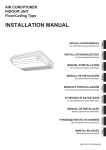
254mm SLIDING MITRE SAW WITH LASER
TSMS250LJ
User Manual-Please read and retain for future reference.
Exploded Assembly Diagram
NOTICE: Actual product may vary from pictures shown.
1
9
2
24
23
28
6
7
27
14
20
10
19
17
18
15
16
Fig. A
1
22
3
2
5
6
4
7
25
8
10
21
11
10
13
12
17
14
Fig. B
26
1. Handle
2. ON/OFF switch
3. Release lever
4. Motor
5. Saw shaft lock
6. Movable blade guard
7. Saw blade
8. Clamping device
9. Top handle
10. Workpiece support
11. Stop rail
12. Table insert
13. Adjustable supporting foot
14. Locking screw
15. Pointer
16. Scale
17. Turntable
18. Fixed saw table
19. Scale
20. Pointer
21. Locking screw
22. Dust bag
23. Drag guide
24. Locking screw for drag guide
25. Safety pin
26. Hex key
27. Laser
28. Battery box
Fig.1
Fig.2
10
Fig.3
Fig.4
14
Fig.5
Fig.6
Fig.7
Fig.8
Fig.9
Fig.10
Fig.11
Fig.12
Fig.13
Fig.14
Fig.15
Fig.16
Fig.17
Fig.18
Contents
Parts List
Technical Information
Safety Instructions
Using your tool
Maintenance
Warranty
Parts List
1
Hex bolt
76
2XWHUÀDQJH
2
%DVH
77
%ODGH
3
%DVHIRRW
78
/RFNZDVKHU
4
+H[VFUHZ
79
,QQHUÀDQJH
5
6WHHOEDOOVSULQJ
80
2XWSXWD[LV
6
6WHHOEDOO
81
.H\ZD\
7
([WHQVLRQURG
82
3KLOOLSVVFUHZ
8
6WDELOL]HUEDU
83
)ODWZDVKHU
9
3KLOOLSVVFUHZ
84
%HDULQJFDS
10
/RFNKDQGOH
85
%HDULQJ
11
3KLOOLSVVFUHZ
86
%HDULQJKRXVLQJ
12
6SULQJZDVKHU
87
%LJJHDU
13
)ODWZDVKHU
88
&LUFOLS
14
3RLQWHU
89
5ROOHUSLQEHDULQJ
15
5RWDWLQJWDEOH
90
'XVWEDJ
16
)ODWZDVKHU
91
'XVWEDJEDU
17
/RFNVFUHZ
92
+H[QXW
18
6FDOH
93
+H[VFUHZ
19
5LYHW
94
Hex bolt
20
3KLOOLSVVFUHZ
95
'HSWKDGMXVWPHQWEORFN
21
.HUI
96
/LQN
22
)ODWZDVKHU
97
3KLOOLSVVFUHZ
23
/RFNVFUHZ
98
6PDOOSODWH
24
Hex bolt
99
*XDUG
1
25
Fence
100
26
Friction plate
101
Guard spring
27
Phillips screw
102
Protection plate
28
%XWWHUÀ\VFUHZ
103
Flat washer
29
Fixed rod
104
Lock nut
30
Link rod
105
Shroud block
31
Step screw
106
Guard shroud block
32
Pressure cover
107
Blade guard
33
Flat washer
108
%ODGHJXDUG¿[HGFRYHU
34
Bolt
109
Lock
35
Phillips screw
110
Phillips screw
36
Support plate
111
Small spring
37
Step screw
112
Axis
38
Roller
113
Self-locking cover
39
Nut
114
Spring seat
40
Big spring
115
Ring
41
Protection guard pin
116
Bearing
42
Stand
117
3URWHFWLRQJXDUG¿[HGFRYHU
43
Step screw
118
Lock screw
45
Washer
119
Self-locking spring
46
Locking pin
120
Lock
47
Locking spring
121
Fan shroud
48
Hollow pin
122
Rotor
49
Guard locking pin
123
Bearing
50
Laser
124
Self tapping screw
51
Laser seat
125
Stator
52
Fixed seat
126
Housing
53
Self tapping screw
127
Label
54
Phillips screw
128
Brush holder
55
%DWWHU\
129
Carbon brush
56
%DWWHU\ER[
130
Brush holder cover
57
Phillips screw
131
Phillips screw
2
Guard ring
58
Battery
132
Spring washer
59
Battery box cover
133
Self tapping screw
60
End cap
134
Handle
61
Rubber pad
135
Self tapping screw
62
Pointer
136
Handle cover
63
Rotating table stand
137
Phillips screw
64
Locking spring
138
Switch
65
Lock handle
139
Handle
66
Spring
140
Induction
67
Double head bolt
141
Cable clamp
68
Flat washer
142
Self tapping screw
69
Locking screw
143
Cable cover
70
Locking handle
144
Cable plug
71
Linear bearing
145
Capacitor
72
Slide rod
146
Key switch
73
Bearing cover
147
Spring
74
Cord clip
148
Rubber screw
75
Hex bolt
149
Locking screw
3
Technical Information
Voltage:
Rated Power:
No Load Speed:
Blade Size:
Cutting Capacity:
NW/GW:
230-240V ~ 50Hz
S1 1600W, S6 2000W (25%)
5000 RPM
254 X 16mm
0º/90º(H x L):78 mm x 340 mm
45º/90º (H x L) : 78 mm x 240 mm
0º/45º(H x L) : 42 mm x 340 mm
45º/45º(H x L) : 42 mm x 240 mm
16/18 kg
Read this entire manual before using this
product. Failure to do so can result in serious injury. Save
this manual for future reference.
Copyright© 2013 by ACL Group Ltd. All rights reserved. This manual or any artwork
contained herein must not be reproduced in any shape or form without the express written
consent of ACL Group Ltd. Diagrams within this manual may not be drawn proportionally.
Due to continuing improvements, actual product may differ slightly from the product
described herein.
4
Read and Keep This Manual
Please read carefully all instructions within this manual. Failure to follow all safety
warnings can result in serious personal injury. The term “Power Tool” in all of the
following warnings refers to your mains operated (corded) or battery operated (cordless) power tool
Important SAFETY Information
This symbol is to warn you of potential personal
injury hazards. Please read carefully the notes along side
this warning to avoid possible injury or death.
General Safety Rules
WARNING! Read all instructions. Failure to follow all instructions listed below may
result in electric shock, fire and/or serious injury. The term “power tool” in all of the
warnings listed refers to corded or cordless power tools.
Work area safety
Keep work area clean and well lit. Cluttered or dark areas invite accidents.
Do not operate power tools in explosive atmospheres, such as in the presence of
flammable liquids, gases or dust. Power tools create sparks which may ignite the
dust or fumes.
Keep children and bystanders away while operating a power tool. Distractions can
cause you to lose control.
Electrical safety
Before use, ensure that the power outlet you are using matches the plug on your power
tool and that the voltage of the outlet matches that of your power tool.
Only use grounded extension cords with power tools fitted with 3 pin plugs and if using
outdoors ensure any extension cord is suitable for outdoor use.
Always try to avoid body contact with grounded surfaces, such as radiators, cooking
ranges and any other fixed appliance with metal surfaces.
5
Do not expose your power tool to wet or damp conditions and NEVER use in rain.
Check regularly the power cord of your machine and any extension cord that you
are using for damage.
Do not carry or pull the machine with the power cord.
Ensure the cord is clear from hot surfaces, oil or sharp objects.
Personal safety
Never use your power tool whilst under the influence of alcohol, drugs or medication.
Tiredness can often cause accidents, stay alert.
Never use your power tool without the correct guards in place.
Always use ANSI approved eye protection and dust mask. Non slip safety shoes and
hearing protectors should be worn at all times when using your power tool.
Ensure any dust collecting device supplied with your machine is connected correctly
before use.
Ensure all loose clothing, long hair or jewelry is kept clear of the machine.
Before plugging your power tool into the power outlet ensure the power tool is in the
OFF position.
Check that wrenches or adjusting keys have been removed. Any wrench or key left
attached to a moving part can result in injury.
Power tool use and care.
Keep your power tool clean and well serviced at all times.
Never adjust or service any power tool before disconnecting from the mains electricity
supply.
Always use the correct tool for the job.
Never force the tool to work harder than it is designed to do.
Never use your power tool with broken parts such as switches, guide fences or leg
stands.
ALWAYS keep your power tools away from children.
Keep cutting tools sharp to ensure less stress on the motor.
Only have your power tool serviced by a qualified repair agent using manufacturers
recommended parts.
Service
Have your power tool serviced by a qualified repair person using only identical replacement parts. This will ensure that the safety of the power tool is maintained.
Develop a periodic maintenance schedule for your tool. When cleaning a tool be careful
not to disassemble any portion of the tool since internal wires may be misplaced or
pinched or safety guard return springs may be improperly mounted. Certain cleaning
agents such as gasoline, carbon tetrachloride, ammonia, etc. may damage plastic parts.
6
When servicing a tool, use only identical replacement parts. Follow instructions in the
Maintenance section of this manual. Use of unauthorized parts or failure to follow
Maintenance Instructions may create a risk of electric shock or injury.
WARNING: For your own safety read Instruction Manual before operating grinder.
A) Wear eye protection.
B) Keep hands out of the path of blades/cutters.
C) Do not operate tool without guards in place.
D) Do not perform any operation freehand.
E) Never reach around cutting tools.
F) Turn off tool and wait for blade/cutter to stop before moving workpiece or changing
settings.
G) Disconnect power(or unplug tool) before changing blade/cutter or servicing.
GENERAL SAFETY INSTRUCTIONS
Read this owner's manual completely and make sure you understand all of its
safety guidelines.
1. KEEP GUARDS IN PLACE and in working order.
2. REMOVE ADJUSTING KEYS & WRENCHES. Before turning on the power tool, make
sure the keys and adjusting wrenches have been removed.
3. KEEP WORK AREA CLEAN. Cluttered areas and benches invite accidents.
4. ALWAYS REMAIN ALERT WHEN THE TOOL IS IN USE. Inattention on the part of
the operator may lead to serious injury.
5. DON’T USE IN A DANGEROUS ENVIRONMENT. Don’t use power tools in damp or
wet locations or expose them to rain. Keep work area well lit.
6. KEEP CHILDREN AWAY. All visitors should remain at a safe distance from work area.
7. MAKE WORKSHOP CHILD-PROOF with padlocks, master switches or by removing
starter keys.
8. USE THE RIGHT TOOL. Don’t force a tool or attachment to do a job for which it was
not designed.
9. USE THE PROPER EXTENSION CORD. Make sure your extension cord is in good
condition. When using an extension cord, be sure to use one heavy enough to carry
the current your product will draw. An undersized cord will cause a drop in line voltage
resulting in loss of power and overheating. Table (see Table 1) shows the correct size
to use depending on cord length and nameplate ampere rating. If in doubt, use the
next heavier gauge. The smaller the gauge number, the heavier the cord.
10. DON’T FORCE THE TOOL. It has been designed to operate at maximum safety
and performance levels.
11. DO NOT FORCE THE MATERIAL BEING CUT. Always let the tool cut at its own
speed.
12. WEAR PROPER APPAREL. Do not wear loose clothing, neckties, rings, bracelets
or other jewelry which may get caught in moving parts. Non-slip foot wear is recommended. Wear protective hair covering if you have long hair.
7
13. ALWAYS USE SAFETY GLASSES. Also use face or dust mask for commercial
cutting operations. Everyday eyeglasses only have impact-resistant lenses, they
are NOT safety glasses.
14. SECURE WORK. Use clamps or a vise instead of your hand to hold work when
practical. This safety precaution allows for proper tool operation using both hands.
15. DON’T OVERREACH. Keep proper footing and balance at all times.
16. MAINTAIN TOOLS WITH CARE. Keep tools clean and in good working condition
for maximum safety performance. Follow instructions for lubricating and changing
accessories.
17. DISCONNECT TOOLS BEFORE SERVICING – when changing accessories, such
as blades, bits, cutters, etc.
18. REDUCE THE RISK OF UNINTENTIONAL STARTING. Make sure switch is in OFF
position before plugging in.
19. USE RECOMMENDED ACCESSORIES. Consult the owner’s manual for recommended accessories. The use of improper accessories may increase risk of injury.
20. MAKE SURE YOU USE THE CORRECT TOOL for the job you are doing.
21. NEVER STAND ON TOOL. Serious injury could occur if the tool is tipped or if the
cutting tool is unintentionally contacted.
22. CHECK DAMAGED PARTS. Before further use of the tool, damaged part(s), (i.e.,
guard) should be carefully checked to determine that it will operate properly and
perform its intended function. Check for alignment of moving parts, binding of moving parts, breakage of parts, mounting and any other condition that may affect the
tools operation. A guard or other part that is damaged should be properly repaired
or replaced.
23. Replace damaged wheels/cutters immediately.
DO NOT USE DAMAGED WHEELS/CUTTERS. They may cause bodily injury.
24. DIRECTION OF FEED. Feed work into the wheel/cutter against the direction of
rotation of the wheel/cuter only.
25. NEVER LEAVE TOOL RUNNING UNATTENDED.
Turn power off. Don’t leave tool until it comes to a complete stop.
26. Double Insulated tools are equipped with a polarized plug (one blade is wider than
the other). This plug will fit in a polarized outlet only one way. If the plug does not
fit fully in the outlet, reverse the plug. If it still does not fit, contact a qualified electrician to install a polarized outlet. Do not change the plug in any way. Double Insulation eliminates the need for the three wire grounded power cord and grounded
power supply system.
This power tool is supplied with all the relevant safety guards and features, it should be
checked before every operation, this manual should be read and kept in a safe place.
Whilst we warn of all the possible risks attached to using power tools any operator must
have read and understood the manual and apply their own caution and common sense
when using this power tool.
8
Following this guide will greatly reduce your risk of electric shock or injury.
Only use qualified repair agents to service this power tool.
Only use qualified electrician to repair any damaged wiring.
NEVER remove the grounding prong from the power toll or extension cord.
Symbols
IMPORTANT: Some of the following symbols may be used on your tool.
V……………….volts
W...................... Wattage
Hz………………hertz
~………………. alternating current
…/m……………revolutions per minute
......................class II construction (double insulated)
Kg………………kilograms
No………………No load speed
DC …………...Direct Current
………………..Conforms to relevant safety standards
…………
Wear hearing protection.Wear eye protection.Wear respiratory protection.
.....................Read the instruction manual
…………... Electric products should not be disposed of with household waste,
please recycle where facilities exist, Check with your Local Authority or
retailer for recycling.
……………..ATTENTION!
……………....Keep hands away, do not touch.
……………....Keep the children away.
Specific Safety Rules
1. Wear eye protection.
2. Keep hands out of path of saw blade. Avoid contact with any coasting blade. It can
still cause severe injury.
3. Do not operate saw without guards in place.
Check blade guard for proper closing before each use. Do not operate saw if blade
guard does not move freely and close instantly. Never clamp or tie the blade guard
into the open position.
4. Do not perform any operation freehand. The workpiece must be secured firmly
against the base and guide fence with a vise during all operations. Never use your
hand to secure the workpiece.
5. Never reach around saw blade.
6. Turn off tool and wait for saw blade to stop before moving workpiece or changing
settings.
7. Unplug tool before changing blade or servicing.
8. To reduce the risk of injury, return carriage to the full rear position after each crosscut
operation.
9. Stopper pin which locks the cutter head down is for carrying and storage purposes
only and not for any cutting operations.
10. Do not use the tool in the presence of flammable liquids or gases.
9
11. Check the blade carefully for cracks or damage before operation. Replace cracked
or damaged blade immediately.
Gum and wood pitch hardened on blades slows saw and increases potential for
kickback. Keep blade clean by first removing it from tool, then cleaning it with gum
and pitch remover, hot water or kerosene. Never use gasoline to clean blade.
12. While making a slide cut, KICKBACK can occur. KICKBACK occurs when the blade
binds in the workpiece during a cutting operation and the saw blade is driven back
rapidly towards the operator. Loss of control and serious personal injury can result.
If blade begins to bind during a cutting operation, do not continue to cut and release
switch immediately.
13. Use only flanges specified for this tool.
14. Be careful not to damage the arbor, flanges (especially the installing surface) or bolt.
Damage to these parts could result in blade breakage.
15. Make sure that the turn base is properly secured so it will not move during operation.
Use the holes in the base to fasten the saw to a stable work platform or bench.
NEVER use tool where operator positioning would be awkward.
16. For your safety, remove the chips, small pieces, etc. from the table top before operation.
17. Avoid cutting nails. Inspect for and remove all nails from the workpiece before
operation.
18. Make sure the shaft lock is released before the switch is turned on.
19. Hold the handle firmly. The saw moves up or down slightly during start-up and
stopping.
20. Make sure the blade is not contacting the workpiece before the switch is turned on.
21. Before using the tool on an actual workpiece, let it run for a while. Watch for vibration
or wobbling that could indicate poor installation or a poorly balanced blade.
22. Wait until the blade attains full speed before cutting.
23. Stop operation immediately if you notice anything out of the ordinary.
24. Do not attempt to lock the trigger in the on position.
25. Stay alert. Blades are extremely dangerous
26. Use only accessories recommended in this manual. Use of improper accessories
such as abrasive wheels may cause an injury.
27. NEVER hold workpiece on right side of blade with left hand or vice versa. This is
called cross armed cutting and exposes user to risk of SERIOUS PERSONAL INJURY.
ALWAYS use vise to secure workpiece.
28. Do not abuse cord. Never pull on the cord to disconnect it from the receptacle.
Keep cord away from heat, oil, water and sharp objects.
29. Some materials contain chemicals which may be toxic. Take appropriate measures
to prevent dust inhalation and skin contact. Follow material supplier safety data.
30. Some materials contain chemicals which may be toxic. Take appropriate measures
to prevent dust inhalation and skin contact. Follow material supplier safety data.
Additional Safety rules for Laser
WARNING: This saw is equipped with a Laser light, DO NOT stare into the beam because
serious injury may occur.
LASER LIGHT - DO NOT STARE INTO BEAM, APERTURE, or into a reflection from
a mirror-like surface.
AVOID EXPOSURE - LASER LIGHT IS EMITTED FROM FRONT GUARD APERTURE.
CAUTION: Use of controls or adjustments, or performance of procedures other than
those specified herein may result in hazardous laser light exposure.
10
DO NOT DISASSEMBLE LASER MODULE. The laser is a CLASS II LASER PRODUCT
that can emit laser power up to 1 mw 650nm, which could result in exposure with the
module disassembled. The laser unit complies with EN60825-1:2007 .
USE OF CONTROLS OR ADJUSTMENTS OR PERFORMANCE OF PROCEDURES OTHER
THAN THOSE SPEC IFIED HEREIN MAY RESULT IN HAZARDOUS RADIATION EXPOSURE.
CAUTION
LASER RADIATION.
DO NOT STARE INTO BEAM.
$92,'(;32685(
/DVHUUDGLDWLRQLV
HPLWWHGIURPWKLVDSHUWXUH
Wave length: 650nm CLASS 2
Max. power output: 1 mW
EN60825-1:2007
WARNING: Do not attempt to repair or disassemble the laser level. If unqualified persons
attempt to repair this laser product, serious injury may result. Any repair required on
this laser product should be performed by authorized service center personnel.
CAUTION: The use of optical instruments with this product will increase eye hazard.
Unpacking
Carefully remove the product and any accessories from the box. Make sure that
all items listed in the packing list are included.
Package contents
A) Saw
B) Clamp
C) Wrench
D) Dust bag
E) Supports
F) User manual
Functional Description
WARNING:Disconnect the plug from the power source before making any
assembly, adjustments or changing accessories.
Such preventive safety measures
reduce the risk of starting the tool accidentally.
Assembly
WARNING:Disconnect the plug from the power source before making any
assembly, adjustments or changing accessories.
Clamp
To install clamp simply insert it into the provided hole on the fence on the right or left
side depending on the cut you are doing and tighten nut. (Fig.1)
Dust bag
Squeeze metal clamp and place over dust outlet and release clamp. (Fig.2)
11
Supports
Insert supports in both ends of table and secure with screw. (Fig.3)
On-Off Switch
Ensure that the switch is in the “OFF” position. If the plug is connected to a receptacle
while the switch is in the “ON” position, the power tool will start operating immediately
and can cause serious injury.
To turn the saw on or off, squeeze and release the on/off switch. (Fig.4)
Turning Laser Beam ON/OFF
CAUTION: LASER RADIATION
Do not stare into beam
To turn on the laser beam, press the upper position (Fig.13) of the switch. Press the
lower position to turn off. Laser line is factory adjusted so that it is positioned within 1
mm (0.04”) from the side surface of the blade (cutting position). Make a test cut and
position material to be cut accordingly.
NOTE: When laser line is dim and almost or entirely invisible because of the direct
sunlight, relocate the work area to a place not exposed to the direct sunlight.
Using your miter saw
Important Note:
Transporting or moving this machine must only be done with the arm in the
locked position using the transit lock pin. (Fig.5)
When assembling your machine do not connect to the power supply until you have
fully read and understood this manual. After carrying out all checks and making any
necessary adjustments check that the machine switch is in the off position, connect to
the power supply and then switch the machine on and off quickly, this will allow you to
check for any loose blades or accessories without the machine gaining full
speed. Disconnect from the power supply before attempting any adjustments.
During manufacturing your machine is set and calibrated to cut accurately however
movement can occur during transit. If you ¿nd that your machine is not cutting
accurately you can make several small adjustments easily.
Resetting the Table to 90 degrees with the Blade
1. Disconnect the machine from the mains.
2. Lock the arm in the transit position
3. Loosen the locking screw (14). (Fig.6)
4. Align the pointer and table to 0 degrees.
5. Tighten locking screw (14).
6. Loosen the Bevel Lock Handle. (Fig.7)
7. Position the saw arm to 0 degrees with the blade 90 degrees to the table surface.
8. Tighten the Bevel Lock Handle.
9. Place a 90 deg. Set square against the table and blade (avoiding contact with the
blade teeth) rotate the blade slowly with a gloved hand, checking that it is aligned
correctly. (Fig.10)
10. Adjust the pointer to read 0 degrees. (Fig.11)
11. Retighten Bevel lock handle.
12
Fence to Table Adjustment
1. Disconnect the machine from the mains.
2. Lock the arm in the transit position
3. Loosen locking screw (14).
4. Align the pointer and table to 0 degrees.
5. Tighten locking screw (14).
6. Loosen the 4 fence screws (Pt. #24)
7. Place a set square against the fence and blade (avoiding the blade teeth) (Fig.10)
8. Adjust the fence until square.
9. Retighten the fence screws.
10.Adjust the pointer to read 0 degrees.
Blade Cutting Depth Adjustment (for use when trenching)
The blade is factory set to cut all the way through a piece of timber under normal use.
If you require a trench cut the blade can be adjusted to cut to your pre-determined
depth.
1. Disconnect from the power supply.
2. Lift the saw Arm
3. Adjust the depth cut (Trenching) stop screw to the desired position. (Fig.12)
Always Use clamp (Fig.1) to secure the material. This clamp can be moved to either
side of the table by loosening the locking knob. Ensure this knob is retightened
before using the saw. Support long lengths using roller support stands.
4. Check depth on waste timber before commencing.
Compound Miter Cuts
A compound miter cut uses a Miter cut and a Bevel cut together.
The main uses for this type of cut are: picture frames, cutting moldings, roof framing
and for making boxes with sloping sides.
It is advisable to make a test cut on a piece of scrap wood before cutting into your
actual work piece.
Basic Cross Cutting with Fixed Blade
1. Pull the release knob and lift the saw arm.
2. Loosen locking screw (14).(Fig.6)
3. Move the table to the required angle.
4. Fully tighten the Miter lock handle. (If the table is not loFNHG¿UPO\LWFDQUHVXOWLQ
personal injury).
Always Use clamp to secure the material. This clamp can be moved to either side of
the table by loosening the locking knob. Ensure this knob is retightened before using
the saw.
Support long lengths using roller support stands.
5. Turn the Laser guide on. (Fig.13)
6. Align the marked location of the cut on the material with the saw blade.
7. Grasp the operating handle and squeeze trigger to turn on the machine.
8. Allow the machine to free run to its maximum speed before making the cut.
9. Push down the release lever (3) to release the machine head (4). Then make the cut.
10. Allow blade to completely stop before raising the arm to retrieve the work piece.
13
IMPORTANT:
Always Use clamp to secure the material. This clamp can be moved to either side of the
table by loosening the locking knob.
Ensure this knob is retightened before using the saw.
Support long lengths using roller support stands.
Slide Cutting
1. Pull and twist the release knob (Fig.9)
2. Pull the saw arm towards you.
3. Position and lock the work piece using the clamp.
4. Grasp the operating handle and squeeze trigger to turn on the machine
5. Allow the machine to free run to its maximum speed before making the cut.
6. Press the guard release trigger
7. Make the cut.
8. Allow blade to completely stop before raising the arm to retrieve the work piece.
Angle (Bevel) Cutting
This type of cut is obtained when the Table is set at 0 degrees and the blade at any
angle required between 0 and 45 degrees left or right (dual bevel).
1. Loosen the Bevel lock. (Fig.7)
2. Move the saw arm to the required angle. (Fig.14)
3. Re-tighten the Bevel lock.
4. Grasp the operating handle and squeeze trigger to turn on the machine.
5. Allow the machine to free run to its maximum speed before making the cut.
6. Make the cut.
7. Allow blade to completely stop before raising the arm to retrieve the work piece.
Changing the blade
DANGER: Do not use any blade larger than the stated capacity of the saw. It may
come into contact with the blade guard and cause harm.
Do not use a blade too thick to allow the outer blade washer to engage with the Àats on
the spindle. This will prevent the blade screw from securing the blade on the spindle.
Do not use this saw to cut metal or masonry
1. Disconnect the machine from the power supply
2. Disengage the saw arm by pushing down on the operating handle pull and twist the
release knob.
3. Raise the arm to its highest position.
4. Hold blade guard in the up position and press spindle lock, (Fig.15) (Rotate blade
carefully until blade locks)
5. Use hex key to remove the blade bolt (Fig.8 & 16) by loosening in a clockwise
direction. Note: This bolt has a left hand thread
6. Remove outer blade washer and blade.
7. Clean and lightly oil outer and inner blade washers, do not remove inner blade
washer.
8. Replace blade ensuring the teeth are in the correct direction for rotation. The blade
has a direction indicator arrow printed on it, the teeth must always face down.
9. Fit outer blade washer.
10. Depress the spindle lock.
11. Replace and tighten the blade lock bolt using the hex key to secure tightly.
+ROGURWDWLQJORZHUEODGHJXDUGDQGEROWFRYHULQSRVLWLRQDQGUH¿WWKH¿[LQJ
screws.
14
13. Attach blade guard retracting arm to the rotating blade guard.
14. Check guard operates freely.
15. Rotate blade carefully ensuring it does not foul the guard.
16. Reconnect to power supply
17. Switch saw on and off before it reaches maximum speed to check for free running.
Maintenance
WARNING: For your own safety, make sure switch is off and unplugged from the
power source before doing any maintenance or adjustments. Replace the power cord
immediately if it is cut, worn, or damaged in any way.
Accessories
CAUTION: Use only accessories or attachments recommended for use with your
THUUDWHNWRROVSHFL¿HGLQWKLVPDQXDO The use of any other accessories or attachments
might present a risk of injury to persons. Only use accessory or attachment for its
stated purpose.
General Maintenance
1. Keep the air vents free from obstruction and clean regularly
2. Check regularly for any dust particles entering the grills around the motor and the
trigger switch. Use a soft brush to remove any dust particles. Wear safety glasses to
protect your eyes whilst cleaning.
3. Regularly wipe any saw dust from the fence. A build-up of dust on the fence can
prevent accurate cutting.
4. Monitor the dust bag and empty when approximately half full. Always empty into an
appropriate container5(0(0%(5GXVWFDQEHKRWDQGFDXVH¿UH
5. If the blade has become dirty, use a blade cleaner (not included) to clean it. Dirty
blades will bind more easily, and will more often overheat and burn the wood as it
cuts. Overheated blades dull more easily.
6. If the Blade has become dull, replace it. Dull blades will cause increased tear-out
and ragged edges on the cuts.
7. Lubricate all moving parts at regular intervals
8. To clean the body of the power tool, only use a soft damp cloth. Do NOT immerse in
water. A mild detergent can be used but NOT petrol or any alcohol based product.
9. After extensive use of this power tool the grease in the gearbox will require replacing
6KRXOGWKHSRZHUFRUGEHFRPHGDPDJHGRQO\DOORZDIXOO\TXDOL¿HGHOHFWULFLDQWR
replace or repair
Replacing carbon brushes
Remove and check the carbon brushes regularly. Replace when they wear down to the
limit mark. Keep the carbon brushes clean and free to slip in the holders. Both carbon
brushes should be replaced at the same time. Use only identical carbon brushes.
Use a screwdriver to remove the brush holder caps. (Fig.17) Take out the worn carbon
brushes, insert the new ones (Fig.18) and secure the brush holder caps.
15
Declaration of Conformity
We ACL Group (Intl.) Ltd, England DN6 8LZ declare that the 254mm mitre saw has been
manufactured according to our full quality assurance procedures.
The declaration is to certify that it conforms to CE, EMC, LVD, MD and RoHS directives:
EN55014-1/A1:2009
EN55014-2/A2:2008
EN61000-3-11: 2000
EN61000-3-2/A2: 2009
All provisions of Annex 1 of Council Directive 2004/108/EC – EMC directive
EN61029-1/A11: 2010
EN61029-2-9: 2009
All provisions of Annex 1 of Council Directive 2006/42/EC – Machinery Directive
2006/95/EC – Low Voltage Directive
RoHS 2011/65/EU
2011/65/EU
Mr. Alan Garnett, UK QA Manager
16
Environmental Protection
RECYCLING: WASTE ELECTRICAL PRODUCTS SHOULD NOT BE DISPOSED OF WITH
HOUSEHOLD WASTE. PLEASE RECYCLE WHERE FACILITIES EXIST. CHECK WITH YOUR
LOCAL AUTHORITY OR RETAILER FOR RECYCLING ADVICE.
Please read the following carefully
ACL Group (Intl) Ltd. and/or it’s distributor has provided the parts list and assembly diagram
as a reference tool only. Neither ACL Group (Intl). Ltd. or its distributor makes any
representation or warranty of any kind to the buyer that he or she is qualified to do any
repairs or replace any parts of this product. ACL Group (Intl) Ltd. and its distributor expressly
state that all repairs or parts replacement should be done by certified or licensed technicians.
The buyer assumes all risk and liability arising out of his or her repairs or parts replacement to
the original product.
12 Months Limited Warranty
If within 12 months from the date of purchase you experience any problems with your product,
please return the product to its distributor/dealer for repair or replacement. This warranty
DOES NOT COVER normal wear, or any damage as a result of accidents, misuse, abuse or
negligence.
ACL Group (Intl) Ltd
Doncaster, England
Email: [email protected]
www.terratekintl.com
17