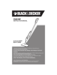
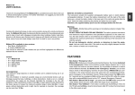
1
Power Stak PPS2200-62NAS This manual covers PowerStak units with frame numbers starting with GC stamped into the mast and shipped March 2014 and after. Installation, Operation and Service Manual Model Number ___________________ Serial # _________________________ Date Placed in Service _____________ IMPORTANT: READ CAREFULLY BEFORE INSTALLING OR OPERATING LIFT FEB 2015 Presto Lifts Limited Power Stacker Warranty Policy Presto Lifts warrants the Power Stacker against defects on the mast, fork carriage, chains, pumps, DC motors, controllers, cylinders and wiring harnesses from faulty material and workmanship for a period of one (1) year from the date of invoice. All wear items such as batteries, wheels, motor brushes, seals, bearings, hydraulic hoses, all switches, battery chargers and forks have a limited warranty against defects in faulty material and workmanship for a ninety (90) day period from the date of invoice and 30 day limited warranty on labor. Please note that prior authorization from Presto Lifts is required on all warranty work. 7KHUHDUHQRLPSOLHGZDUUDQWLHVRIDQ\NLQGPRUHVSHFL¿FDOO\WKHUHDUHQRZDUUDQWLHVRIPHUFKDQWDELOLW\RU¿WQHVVIRUDQ\SDUWLFXODUSXUSRVH3UHVWR/LIWV¶VROHZDUUDQW\VKDOOEHDVVHWIRUWKLQWKLV limited warranty. Presto Lifts will elect to repair or replace a defective component without charge, if any components should become defective within the limited warranty period. Proof of purchase is required for warranty. The charge for shipping the defective component is the responsibility of the buyer and must be accompanied with an RMA number. The shipping charge to return the component to the buyer is the responsibility of Presto Lifts, Inc. This limited warranty does not cover labor expense for removal or reinstallation of components after thirty days. This limited warranty shall not cover, among other things: damages resulting from foreign matter or water, failure to provide reasonable and necessary maintenance, and if applicable, use of product while charger is plugged into an AC outlet, or failure to follow operating instructions. The limited warranty is not valid for damage resulting from negligence, accident, unreasonable use, abuse or misuse, exceeding data plate capacities or altering the product without Presto Lifts authorization. Presto Lifts expressly disclaims and excludes any liability for consequential, incidental, indirect RUSXQLWLYHGDPDJHVRU¿QDQFLDOORVVWRSHRSOHRUSURSHUW\UHVXOWLQJIURPDQ\EUHDFKRIZDUUDQW\RU the operation or failure of this product. Presto Lifts makes no representation that this product complies with local, state, or federal safety/ product standards codes. Should this product fail to comply in any way with those codes, it shall not be considered a defect of materials or workmanship. Presto Lifts shall not be held liable for any damages resulting from noncompliance. It is the dealer’s responsibility to exercise this limited warUDQW\7KLVOLPLWHGZDUUDQW\LVSURYLGHGWRWKHRULJLQDOSXUFKDVHUGH¿QHGDVWKHRULJLQDOHQGXVHU DQGLVQRQWUDQVIHUDEOH7KLVFRQVWLWXWHVWKHFRPSOHWHDQG¿QDODJUHHPHQWLQYROYLQJ3UHVWR/LIWVDQG limited warranty obligations for products. This manual was current at the time of printing. To obtain the latest, most updated version, please contact the &XVWRPHU6HUYLFH'HSDUWPHQWRUJRWRRXUZHEVLWHZZZ3UHVWR/LIWVFRP\RXZLOO¿QGDFRPSOHWHOLVWRIFXUrent Owner’s Manuals to print. PRESTO OWNER’S MANUAL Page 2 POWER STAK TABLE OF CONTENTS S E C T I O N 1: Limited Warranty ................................................................................................................................................2 Wheel Traction and Straddle Leg Set-Up ...........................................................................................................4 Introduction .........................................................................................................................................................5 Responsibility of Owners and Users ...................................................................................................................6 S E C T I O N 2: &HUWL¿HG2SHUDWRU7UDLQLQJ .................................................................................................................................7 Safety .................................................................................................................................................................7 S E C T I O N 3: Installation...........................................................................................................................................................9 A. Inspection ....................................................................................................................................................9 B. Removing from Pallet ..................................................................................................................................9 C. Preparation for Use.......................................................................................................................................9 S E C T I O N 4: Operation...........................................................................................................................................................10 A. Operating Instructions .................................................................................................................................10 B. Daily Operations Maintenance Checks .......................................................................................................11 Suggested Daily Operator Checklist .................................................................................................................12 S E C T I O N 5: Battery Maintenance .........................................................................................................................................13 A. Preparing to Charge a Battery ....................................................................................................................13 B Charging the battery ....................................................................................................................................13 C. Warnings and Battery Info...........................................................................................................................13 D. Battery maintenance ....................................................................................................................................13 E. Charger Operations ......................................................................................................................................13 S E C T I O N 6: Maintenance ......................................................................................................................................................14 A. Weekly Operations Maintenance Checks....................................................................................................14 B. Monthly Operations Maintenance Checks .................................................................................................14 S E C T I O N 7: Troubleshooting ................................................................................................................................................15 ORDERING REPLACEMENT PARTS ...........................................................................................................................29 RESTOCKING POLICY ..................................................................................................................................................30 RETURN MATERIALS AUTHORIZATION .................................................................................................................31 LIST OF FIGURES: Figure 1: Operational Buttons......................................................................................................... 7 Figure 2: Stacker Body Components............................................................................................ 16 Figure 3: Control Pod ................................................................................................................... 17 Figure 4: Steering Component ..................................................................................................... 18 Figure 5: Drive Unit....................................................................................................................... 19 Figure 6: Carriage Assembly ........................................................................................................ 20 Figure 7: Mast Components ......................................................................................................... 21 Figure 8: Power Unit ..................................................................................................................... 22 Figure 9: Hydraulic System .......................................................................................................... 23 Figure 10: Hydraulic Schematic.................................................................................................... 24 Figure 11: Control Panel ............................................................................................................... 25 Figure 12a & b: Electrical Schematic Diagram ........................................................................ 26-27 Figure 13: Battery Connection ...................................................................................................... 28 PRESTO OWNER’S MANUAL Page 3 POWER STAK CRITICAL PROCEDURE FOR PROPER WHEEL TRACTION Proper Drive Wheel traction is obtained for the PowerStak Straddle unit using this Procedure $OO3RZHU6WDN0RGHOVDUHGHVLJQHGDQGLQWHQGHGWRRSHUDWHRQDQXQ¿QLVKHGFRQFUHWHÀRRUVXUIDFH,IDQ\ 3RZHU6WDNLVRSHUDWHGRQVPRRWKRUSROLVKHGFRQFUHWHVHDOHGFRQFUHWHHSR[\VHDOHGÀRRUOLQROHXPRU RWKHUVPRRWKVXUIDFHV'ULYH:KHHOWUDFWLRQSHUIRUPDQFHPD\EHDIIHFWHG,IWUDFWLRQLVVXHVDUHHQFRXQWHUHG Rubber Drive Wheels are available through special order. Please contact Customer Service at Presto Lifts 1-800-343-9322 When any PowerStak is operated on a wet, oily, powdery, sandy or non-uniform liquid or granular surface Drive Wheel traction performance will be affected and loss of traction will occur. SET-UP PROCEDURE FOR POWERSTAK STRADDLE LEGS NOTE: STRADDLE LEGS MUST BE ADJUSTED IN ACCORDANCE WITH THIS PROCEDURE 1. 3RZHU6WDNXQLWORFDWHGRQÀDWFOHDQXQLIRUPVXUIDFHXQORDGHGIRUNVUDLVHGDPLQLPXPRI´RIIWKHÀRRU 2. 'HWHUPLQHWKHGHVLUHGUHTXLUHGVWUDGGOHZLGWKGLPHQVLRQLQFKHVJUHDWHUWKDQSDOOHWZLGWK´RQHDFKVLGHRI the pallet or load, up to a maximum of 50 inches inside width) 3. Be sure to fully loosen all bolts before moving stabilizing legs. Adjust one stabilizer leg at a time – using a pry bar, pinch bar, rubber mallet etc. move the straddle leg out from the base tube to the desired position. Do not PRYHWRRIDUVHHSLFWXUHEHORZLIWKHó´ZLGHSDLQWHG:KLWH/LQHLVYLVLEOHWKHOHJLVSXOOHGRXWWRRIDU0D[LPXPPRYHPHQWò´IRUHDFKOHJIRUSRXQGXQLWV 4. Adjust second Straddle Leg – using a pry bar, pinch bar, rubber mallet etc. move the straddle leg out from inside the base tube to the desired straddle width position. 5. Straddle Legs must be symmetrically adjusted, both legs adjusted to the same extended dimension! CRITICAL – STRADDLE BOLT TIGHTENING SEQUENCE & PROCEDURE Set up procedure for PowerStak Straddle legs with 5 Bolts: 5() %2/76 %2/7 %2/76 %2/7 %2/7 %2/7 :+,7(/,1( -8676+2:,1* 0$;,080 Back off all bolts and follow steps. First - tighten Bolt 1 to 85 foot pounds Second - tighten Bolts two (2) to 85 foot pounds Third - tighten Bolt 3 to 85 foot pounds Fourth – tighten Bolt 4 to 25 foot pounds - NOT 85 foot pounds! Last - securely tighten all lock nuts PRESTO OWNER’S MANUAL Page 4 NOTE: When adjusted correctly, white line cannot be seen. POWER STAK SECTION 1 INTRODUCTION This manual attempts to provide all of the information necessary for the safe and proper installation, operation and maintenance of Presto Lifts Inc. battery operated, Power Stak. It is important that all personnel involved with the installation, maintenance or operator of the stacker read this manual. Additional manuals are available upon request or at www.PrestoLifts.com. Each Presto stacker is equipped with nameplate, serial QXPEHUDQGPRGHOLGHQWL¿FDWLRQV3OHDVHUHIHUWRWKHVH numbers when ordering parts or requesting further information. The Presto stackers are designed for lifting, lowering and positioning a wide variety of loads. WHERE UNIQUE SITUATIONS ARISE, WHICH ARE NOT COVERED IN THIS MANUAL, CALL PRESTO LIFTS FOR FURTHER INSTRUCTIONS. The battery operated stackers are designed for inplant/non-hazardous locations only. They can be used in a 8' or larger aisle. These units are not for personnel lifting. PRESTO OWNER’S MANUAL This machine is designed for powered travel and should not be manually moved by applying force to the Control Pod Handles The Control Pod and steering arm should only be moved side to side when the machine is under power The Control Pod and steering arm should be lowered to the drive position and power, Forward or Reverse, is engaged by moving the thumb wheel in the direction of desired travel then the steering arm can be moved side to side for directional steering. Pushing or pulling on the Control Pod Handles when the unit is not powered can lead to damage and/or breakage Page 5 POWER STAK Responsibility of Owners and Users Inspection and Maintenance The device shall be inspected and maintained in proper working order in accordance with Presto’s owner’s manual. Removal from Service Any device not in safe operating condition such as, but not limited to, excessive leakage, missing rollers, pins, or fasteners, any bent or cracked structural members, cut or frayed electric, hydraulic, or pneumatic lines, damaged or malfunctioning controls or safety devices, etc. shall be removed from service until it is repaired to the original manufacturer’s standards. Repairs $OOUHSDLUVVKDOOEHPDGHE\TXDOL¿HGSHUVRQQHOLQFRQIRUPDQFHZLWK3UHVWR¶VLQVWUXFWLRQV Operators Only trained personnel and authorized personnel shall be permitted to operate PowerStak. Before Operation Before using the device, the operator shall have: Read and/or had explained, and understood, the manufacturer’s operating instructions and safety rules. Inspected the device for proper operation and condition. Any suspect item shall be carefully exDPLQHGDQGDGHWHUPLQDWLRQPDGHE\DTXDOL¿HGSHUVRQDVWRZKHWKHULWFRQVWLWXWHVDKD]DUG$OO LWHPVQRWLQFRQIRUPDQFHZLWK3UHVWR¶VVSHFL¿FDWLRQVKDOOEHFRUUHFWHGEHIRUHIXUWKHUXVHRIWKH PowerStak. During Operation The device shall only be used in accordance with this owner’s manual. Do not overload. Ensure that all safety devices are operational and in place. 0RGL¿FDWLRQVRU$OWHUDWLRQV 0RGL¿FDWLRQVRUDOWHUDWLRQVWRDQ\3UHVWRLQGXVWULDOSRVLWLRQLQJHTXLSPHQWVKDOOEHPDGHRQO\ZLWK written permission from Presto. PRESTO OWNER’S MANUAL Page 6 POWER STAK SECTION 2 CERTIFIED OPERATOR TRAINING <RXPXVWEHWUDLQHGDQGFHUWL¿HGWRRSHUDWHWKLVSRZHUHGVWDFNHU)HGHUDOODZVWDWHVWKDWRQO\SURSHUO\ trained operators are permitted to operate a powered industrial stacker and that your employer must train \RXDQGFHUWLI\WKDW\RXDUHTXDOL¿HG26+$4)5(GLWLRQ Presto lifts does not offer operator training. Operator training programs may be offered by your local Presto Lifts dealer or obtained online. Enter, "powered industrial truck operator training" into a search engine. SAFETY ALERT SYMBOLS AND SIGNAL WORDS The safety of all persons operating, maintaining, repairing, or in the vicinity of this equipment is of paramount concern. This is a powerful machine with moving parts, and is capable of causing personal injury if proper precautions DUHQRWWDNHQ7KHUHIRUHWKURXJKRXWWKLVPDQXDOFHUWDLQKD]DUGVKDYHEHHQLGHQWL¿HGZKLFKPD\RFFXULQWKHXVH of the machine, and there are appropriate instructions or precautions which should be taken to avoid these hazards. In some cases, there are consequences which may occur if instructions or precautions are not followed. Below are WKHV\PEROVDQGVLJQDOZRUGVDORQJZLWKWKHLUGH¿QLWLRQVUHIHUHQFHGIURP$16,=3URGXFW6DIHW\6LJQV and Labels. Safety Alert Symbols These are the safety alert symbols.. They are used to alert you to potential physical injury hazards. Obey all safety messages that follow this symbol to avoid possible injury or death. For use with DANGER signal word (Red Background) For use with WARNING signal word (Orange Background) For use with CAUTION signal word (Yellow Background) Signal Words 7KHPHDQLQJRIGLIIHUHQWVLJQDOZRUGVDVGH¿QHGE\$16,6WDQGDUG=LQGLFDWHVWKHUHODWLYH seriousness of the hazardous situation. DANGER indicates a hazardous situation which, if not avoided, will result in death or serious injury. (Red Background) WARNING indicates a hazardous situation which, if not avoided, could result in death or serious injury. (Orange Background) (Yellow Background) CAUTION, used with the safety alert symbol, indicates a hazardous situation which, if not avoided, could result in minor or moderate injury. NOTICE is used to address practices not related to personal injury. (Blue Background) A. B. SAFETY INSTRUCTIONS (or equivalent) signs indicate safetySAFETY related instructions or procedures. INSTRUCT I OBackground) NS (Green PRESTO OWNER’S MANUAL Page 7 POWER STAK The battery operated stackers are very powerful lifts capable of doing large amounts of work. DO NOT OPERATE THESE LIFTS WITHOUT CAREFULLY READING THIS MANUAL. In order to provide for the safe operation of these stackers, 3UHVWR /LIWV ,QF KDV LGHQWL¿HG FHUWDLQ KD]DUGV WKDW may occur during the maintenance and use of these lifts. For safety reasons these units are designed to be serviced or repaired in the fully lowered position. If performed properly, this will greatly reduce the possibility of injury. FDXJKWEHWZHHQWKHVWDFNHUDQGD¿[HGREMHFWZLOO be crushed or even cut off. ,IWUDYHOLQJIRUNV¿UVWNHHSERWKKDQGVRQ the control handle and be careful when changing direction of travel. Keep your feet clear of the stacker. Keep the stacker under control at all times. Operate at a speed that allows you to stop safely. Be even more careful on slippery or uneven surIDFHV'RQRWUXQRYHUREMHFWVRQWKHÀRRU Perform all stacker movements smoothly and at a speed that will give you time to react if an emergency occurs. WARNING! When servicing the unit: 1. Key should be in "OFF" position. 2. E-stop should be depressed. 3. Disconnect the batteries at the terminals. Do not perform any repair work on lifts if there is a load on the forks or platform. Do not perform any repair work if the forks or platform is in the raised position. All personnel must stand clear of the lift while in motion. Do not put hands or feet under the forks or platform. Do not stand underneath the forks or platform. Do not stand in front of the stacker while in motion. Do not stand, sit or climb on the lift. Do not use the lift on soft, uneven or unstable surfaces. Do not exceed the load center or capacity. WARNING! 7LSRYHUVDQGIDOOVDUHYHU\VHULRXVDFFLGHQWV\RXFDQ be crushed or even killed. To prevent injury, know where you are at all times and follow the rules of safe stacker operation. Be careful when working around docks, dockboards and trailers. Stay away from the edge of docks and ramps. Check to make sure the wheels of truck or trailers are chocked. Travel with the load or forks close to the ground. Watch for overhead obstructions. Perform all stacker movements smoothly and at a speed that will give you time to react in an emergency. Keep your hands and feet away from all moving parts such as masts, chains, forks or wheels. Never stand on or under the forks, or allow anyone else to stand on or under them. Never ride on the stacker or allow anyone else to ride. There is no safe place to sit or stand. Before you leave your stacker, be sure to ORZHUWKHIRUNVWRWKHÀRRU6KXWWKHVWDFNHURII with the key. You or others around you can be seriously injured or even killed if you don't use this stacker correctly. Read and obey all warnings and instructions in this manual and on the stacker. It is your responsibility before starting work to make sure it is in good working order. Always be alert to the area around you and watch where you are walking. Be careful that you don't get pinned RUFUXVKHGEHWZHHQWKHVWDFNHUDQGD¿[HGREMHFWVXFK as a wall or post. Watch your hands and feet. A foot or hand PRESTO OWNER’S MANUAL Page 8 POWER STAK WARNINGS DO NOT use this stacker until you have been trained and authorized to do so. DO NOT operate until you have read all warnings and instructions. DO NOT exceed load center or load weight capacities (check capacity plate). DO NOT operate until you have checked the conditions of the stacker: lift systems, forks, chains, and cables. DO NOT use if any part is damaged, worn or not working properly. DO NOT use on ramps or inclines. Only smooth level surfaces. DO NOT use for lifting or carrying people. DO NOT handle unbalanced, unstable or loosely stacked loads. DO NOT travel with forks or platform in an elevated position. DO NOT handle tall, unsecured or unstable loads that could fall. DO NOT allow people to stand or pass under forks or platform with or without load. DO NOT operate when parts of anyone’s body may be close to mast structure or any moving parts. DO NOT drop loads on platform or forks. DO NOT alter or modify this stacker in any way. SECTION 3 INSTALLATION A. INSPECTION: Upon receipt of the stacker, inspect the equipment completely to determine if there is any shipping damage, and that the lift is complete. Presto tests and inspects every piece of equipment prior to shipment. If damage LVDSSDUHQWDIUHLJKWFODLPPXVWEH¿OHGZLWKWKHIUHLJKW company. Do not use the stacker if there appears to be any damage. With the stacker in a lowered position, check the following: Check for signs of damage especially to the back cabinet that houses the battery, electrical/ hydraulic power pack. Check all electrical and hydraulic connections for tightness. Remove back panel. 1. Turn key switch to "OFF" position. 2. Push in E-stop and unscrew the red knob, 3. Lift off back panel. There is enough wire to the key switch to allow the panel to be set aside. PRESTO OWNER’S MANUAL Inspect for any bent or damaged parts. B. REMOVING FROM PALLET PowerStak is shipped out on a pallet or skid. Prior to removing the unit from the pallet or skid, remove all tie down straps and packaging. Visually inspect the unit as closely as possible. With an overhead hoist or forklift, carefully pick up the unit taking into consideration the center of gravity of the unit. If you choose to pick the unit with an overhead hoist, use a nylon sling and hoist with a minimum of 2,000-lb. capacity. The nylon sling will not do any damage to the steel construction of stacker. Pick the unit up. On conventional masts use the top crossmember of the lift. On narrow masts the cover must be removed to access lifting equipment. Be careful of the stacker swinging once fully lifted off the pallet or skid. Have all personnel completely cleared from the area. Pick the unit up approximately six inches above the pallet or skid. Once raised, remove the pallet or skid from below the lift. Do not move the lift around in the air. Lower the stacker on the ground. C. PREPARATION FOR USE PowerStak left our factory in new condition. It has been inspected and weight tested to assure all performance standards have been met. Visually inspect the stacker for damage. Check for attachments and accessories that may have been ordered. If there is any damage or missing parts, report it to your carrier and your Presto dealer immediately. Remove all metal/plastic bands, cardboard and other material used for shipping purposes. Check to see if chains are in place, and that the lift system is in working order. Inspect for oil leaks. Connect battery cable. Check cables and wires on battery charger as well as battery. Note: The travel speed is preset at the factory. For travel speed adjustment, please contact customer service at Presto Lifts 1-800-343-9322 Page 9 POWER STAK SECTION 4 OPERATION A. OPERATING INSTRUCTIONS: To Raise and Lower: There are two buttons located on both sides of the handle. The inside one is for lowering the forks. The outside one is for raising the forks. When operating, always make sure the load being lifted is within the loading capacity of your stacker and the load has been stacked safely on the pallet. Also, make sure that the length of the forks corresponds to the length of the pallet. In this way, the load rollers will place themselves in the opening at the end of the pallet, so that when you raise the forks, you will not break the bottom boards of the pallet. Always make sure that when entering the pallet that the forks are in the fully lowered position. Be careful when lifting pallets that are too short or too long for the stacker. It might destroy your pallet by breaking the bottom boards, and if the forks project through the end of the pallet, the tips of fork may go into the next pallet that is behind the pallet that you are lifting, which may bend the tips of forks and overload the capacity of the stacker. Travel Function: 7RWUDYHOURWDWHWKHEXWWHUÀ\FRQWUROVWKURWWOHRQWKHXSSHUSDUWRIWKHKDQGOH:KHQURWDWLQJWKHEXWWHUÀ\FRQtrol towards the forks, the stacker runs forwards in the Figure 1: Operational buttons IRUNV¿UVWGLUHFWLRQ:KHQURWDWLQJWKHEXWWHUÀ\WRZDUGV the operator, the stacker runs in the reverse direction. Always make sure the stacker clears any obstruction when traveling, and that your path of travel is clear of people. Never carry loads above the loading capacity of the stacker. It is suggested that when traveling without a load, the forks be in the lowered position. The speed of the stacker is increased by the degree of the rotation LQHLWKHUGLUHFWLRQLWIXQFWLRQVOLNHDWKURWWOH:KHQ\RX UHOHDVH\RXUKDQGIURPWKHEXWWHUÀ\FRQWUROLWDXWRPDWLcally will resume to the neutral position and the speed of the stacker will slow down, and come to a stop Turtle Speed Travel: :KHQWKHEXWWHUÀ\FRQWUROLVHQJDJHGIRUZDUGWRZDUG the forks) or reverse (toward the operator if the operator simultaneously engages the turtle speed button the forward and/or reverse speed is limited to 50% of full speed or turtle speed. 7KHRSHUDWRUFDQHQJDJHWKHEXWWHUÀ\IRUZDUGZLWKWKH right hand and engage the turtle speed button with the left hand. 7KHRSHUDWRUFDQHQJDJHWKHEXWWHUÀ\IRUZDUGZLWKWKH left hand and engage the turtle speed button with the right hand. The reverse operation is also controlled with either hand. The turtle speed is maintained only when the turtle speed button is engaged. When the turtle speed button is not engaged the unit will operate at full speed. The turtle speed button is a maintained contact operation. Control Pod Top Turtle Speed Control Pod Bottom PRESTO OWNER’S MANUAL Page 10 POWER STAK Inspect the lift for damaged or worn parts. Do not use if not in safe operating condition. Use lift on hard level surfaces only. Make sure load is evenly distributed, not loose or unstable, and is as far back on platform or forks as possible. Do not pick up loads on tips or forks or edge of platform. For fork models, adjust forks to the maximum practical width. Pick up loads on both forks. Do not overload. Check load center and load weight capacities on the nameplate. Make sure travel and work area is clear of obstructions. Check overhead clearance before lifting loads or transporting. Electric Brake: Your stacker is equipped with an electric magnetic brake. The brake is applied when the handle is in its vertical position between 10 – 15 degrees and lowered position between 80 – 90 degrees. The brake could be released when you pull down the handle at any point between 15 – 80 degrees. Always make sure the brake is released before operating the stacker. When the stacker is running, you could brake the stacker by raising the handle to its vertical position or lowering the handle to LWVORZHVWSRVLWLRQ2UWRWXUQWKHEXWWHUÀ\FRQWUROVLQ the opposite direction, the change in direction of the motor will slow down, stop, and reverse the direction of stacker. When parked, the handle will spring back to the full vertical position with the brake applied and the forks in lowered position. Reversing Safety: At the end of the handle there is a large, red reversing bar (belly button switch) that is designed to protect the operator from injury. When the operator runs the stacker backwards, and the end of the handle comes in contact with the operator’s body, the stacker will automatically reverse direction and travel away from the operator. When the reversing safety bar comes in contact with your body during operation, immediately UHOHDVH\RXUKDQGVIURPWKHEXWWHUÀ\FRQWURODQGSXWWKH handle up to its vertical position or down to its lowest position and the brake is on. The reversing safety bar will automatically resume to its original position after being activated. Horn: As standard equipment, a horn that is located on the top of the handle. AUTHORIZED OPERATORS SHOULD READ AND UNDERSTAND ALL INSTRUCTIONS, PRECAUTIONS AND WARNINGS. IMPROPER USE OF THIS LIFT TRUCK COULD RESULT IN INJURY AND/OR DAMAGE TO LOAD AND EQUIPMENT. PRESTO OWNER’S MANUAL B. DAILY OPERATIONS MAINTENANCE CHECKS: 1. Battery A. Check for corroded and loose terminals. A white powder substance will be present if there is any existing corrosion. B. Visually inspect for any cracks or damage to the casing. C. Check for loose battery tie-downs. 2. Charger A. Inspect wire connections. B. Check power cord for nicks/damage. C. Check power charger for proper mounting. 3. Hydraulic System D. E. ) G. 4. Inspect pump and cylinder for oil leaks. Check hydraulic oil level. &KHFNK\GUDXOLF¿WWLQJVDQGKRVHV Check ram for nicks/damage. Frame Assembly A. Check chain roller assembly connections. B. Check for any worn or damaged parts. Page 11 POWER STAK DAILY OPERATOR CHECK LIST CHARGE CONDITION/BATTERY CHECK LIST 1. Check Battery Discharge Indicator (Fuel Gage and Hour Meter) – Be sure unit is showing proper Charge Level before operating unit 2. Check to be sure Charging Cord is Unplugged and properly stowed before operating unit 3. Inspect Battery Wire Connections – All connections should be tight with No Corrosion (white powder) showing at the Battery Terminals 4. Inspect Battery Case – There should be no cracks or visible damage to the Battery Case WALK AROUND INSPECTION 1. Check general condition of Stacker (loose or broken parts, oil, dangling wires, dents, cracked covers etc.) 2. Check metal frame, mast, carriage and font load supports for cracked welds, worn or ÀDWUROOHUVORRVHRUGLVFRQQHFWHGFKDLQVORRVHSLQVPLVVLQJVQDSULQJVDQGORRVHRU missing hardware – bolts, nuts washers etc. 3. Check for evidence of hydraulic leaks 4. Make sure all precautionary labeling is in place and legible FUNCTIONAL INSPECTION 1. 2. 3. 4. 5. Check Drive – Forward and Reverse Function Check Lift – Up and Down Function Check Function for Belly Button Reverse Check Horn Function Check Brake Function OPERATOR ID DATE DO NOT USE OR OPERATE STACKER IF ANY FUNCTION IS NOT OPERATING PROPERLY OR IF STACKER APPEARS UNSAFE IN ANYWAY REPORT CONCERNS TO SUPERVISOR IMMEDIATELY! PRESTO OWNER’S MANUAL Page 12 POWER STAK SECTION 5 A. PREPARING TO CHARGE A BATTERY DANGER Never alter the AC cord or plug provided. If it will QRW¿WRXWOHWKDYHSURSHURXWOHWLQVWDOOHGE\DTXDOL¿HGHOHFWULFLDQ,PSURSHUFRQQHFWLRQFDQUHVXOWLQD risk of an electric shock. 1. Always turn off E-stop and key switch before working with the batteries. 1. Disconnect the charger from the 115 volt wall outlet once the indicators read fully charged. BATTERY MAINTENANCE 2. Be sure the area around the stacker and the battery is well ventilated while battery is being charged. 3. The battery terminals, connections and wiring connections should be clean and free of corrosion. When cleaning any of these components wear a face shield or other suitable protective eyewear. B. BATTERY CHARGING Charging must be performed with the charger that is provided with or prewired into the machine. During charging, the temperature in the battery must not exceed 120 F. Charging simultaneously with truck operation is not recommended. Plug the charger into a 115 volt outlet. Charge until the battery gauge indicator lights show fully charged (approximately 6-8 hours). E. CHARGER OPERATION LED Instruction: Red light on: Charge error (Voltage <11V) 5HGÀDVKLQJOLJKW%DWWHU\UHYHUVHGSRODULW\ <HOORZÀDVKLQJOLJKW1REDWWHU\FRQQHFWHG Yellow light on: Normal charging *UHHQÀDVKLQJOLJKWFKDUJHG Green light on: Fully charged %DWWHU\'LVFKDUJH,QGLFDWRU%', Operation C. WARNINGS AND BATTERY INFORMATION $YRLGXVHRIRSHQÀDPHQHDUEDWWHULHV$WWHPSHUDWXUHV around freezing point, battery capacity is reduced by 30%. The battery terminals, connections and wiring should be clean and free of corrosion. When cleaning any of these components, wear a face shield or other suitable protective eyewear. Read, understand, and folORZDOOEDWWHU\DQGEDWWHU\PDQXIDFWXUHU VVSHFL¿FSUHcautions while working with and/or charging batteries. D. BATTERY MAINTENANCE To measure the voltage, use a digital voltmeter (DC) on the battery poles. The truck must not have been in use for the previous 30 minutes. Here, second from left LED blinks indicating reserved power is above 70% At this point we recommend charging the system Two leftmost LEDs blinking indicate EMPTY RECOMMEND charging the system BEFORE the BDI indicates EMPTY IN ORDER TO EXTEND BATTERY LIFE VOLTAGE Approx. 12.7 V Fully charged Approx. 12.2 V 1/2 charged Approx. 12.0 V 1/4 charged Approx. 11.6 V Discharged PRESTO OWNER’S MANUAL Page 13 POWER STAK SECTION 6 MAINTENANCE B. MONTHLY OPERATIONS MAINTENANCE CHECKS: %DWWHU\PDLQWHQDQFHIUHH Operation of Presto Power Stak is very simple — as is their construction. They require very little maintenance. Reasonable care will result in excellent trouble-free performance. The Power Stak is designed for one-man operation and ease of performance. *UHDVHÀRRUZKHHOVDQGFDVWHUVDWOHDVWRQFH a month Use only Hydraulic Oil AW32 or Dextron III in the hydraulic system. Do not overload your lift. Check brakes, steering mechanisms and controls before each use. A. Clean terminals. B. Clean battery compartment area if there are signs of corrosion. 2. A. Clean and inspect hydraulic cylinder. B. Lubricate chain with a rust inhibitive lubricant (light machine oil). C. Check chain tension. It should be even on both chains. The chain should be tight enough so that it does not come off of the roller assembly. 3. A. WEEKLY OPERATIONS DAMAGE: Check for bent, dented, worn or broken parts. LEAKS: Check hydraulic system for leaks and hydrualic oil level. WHEELS AND CASTERS: Check for wear and that they are turning smoothly. LIFT CHAINS: Check to see that they are in place and not loose. Frame Assembly A. Clean and lubricate all roller bearings, cam followers and all moving parts. B. Clean and inspect all welds. C. Check wheels for wear and damage. D. Inspect nameplate for legibility. Place the serial and model number shown on the nameplate on the cover of the manual for future reference. MAINTENANCE CHECKS: LIFT SYSTEM: Check to assure that there is no binding or excessive play in the forks. Check for quiet and smooth operation of the lift cylinder. Check all moving parts and linkage. Hydraulic System 4. Electrical A. Check batteries, motors, controllers, limit switches, electrical conductors and connections. CAUTION: DO NOT USE LIFT IF IT IS NOT OPERATING PROPERLY, OR APPEARS UNSAFE IN ANY WAY! FORKS: Check that they are not bent or cracked. BRAKE: Ensure the brake works properly. CABLES; WIRES: Check that there are no loose cables or wires. LABELS: Ensure all precautionary labels and guards are in place. PRESTO OWNER’S MANUAL Page 14 POWER STAK SECTION 7 TROUBLESHOOTING Before starting the troubleshooting, you have to: A. Put the truck on an even and solid surface. B. Turn off key switch or disconnect the battery terminals. 8QLWZLOOQRWOLIWPRWRUGRHVQRW UXQ )DXOW\ZLULQJIURPIXVHWROLIWVZLWFKLQKDQGOH )DXOW\OLIWVZLWFK )DXOW\ZLULQJIURPEDWWHU\SRVLWLYHWHUPLQDOWR pump contactor to pump motor %XUQHGRXWEUXVKHVLQSXPSPRWRU /RZK\GUDXOLFSUHVVXUHFDXVHGE\ ¨ Pressure relief valve needs adjustment ¨ Pump check valve stuck open ¨ Faulty solenoid valve )DXOW\ZLULQJIURPOLIWVZLWFKWRVROHQRLG )DXOW\OLIWFRQWDFWRU 'HIHFWLYHFRQWUROFLUFXLWIXVH &KDLQRUUROOHUERXQG &KHFNRLOOHYHO 2. Forks will not lower /RRNIRUELQGLQJLQFKDLQVRUUROOHUV 3. No electrical power Dead Batteries: ¨ Keyswitch on "OFF" position ¨ E-stop button depressed ¨ Loose or dirty battery connections ¨ Blown fuse(s) )DXOW\ZLULQJIURPIXVHWRWUDYHOFRQWUROVZLWFK )DXOW\FRQWUROVZLWFK )DXOW\ZLULQJIURPWUDYHOFRQWUROVZLWFKGLUHFWLRQ contactor )DXOW\FRQWDFWRU PRESTO OWNER’S MANUAL Page 15 POWER STAK Figure 2: Stacker Body Components Item 1 2 3 4 5 6 7 8 9 10 11 12 Description Spacer Load Wheel Bearing Spindle Bolt Straddle Leg (RH) Nut Bolt Bolt Seat Drive Wheel Cover Rear Cover Qty 4 2 4 2 4 1 10 10 2 1 1 1 PRESTO OWNER’S MANUAL Item 13 14 15 16 17 18 19 20 21 22 23 Description Chain Cover Straddle Leg (LH) Limit Cover Bolt Top Cover Stacker Body Assembly Screw Caster Assembly Bolt Spring Washer Nut Page 16 POWER STAK Qty 1 1 1 8 1 1 10 1 4 4 4 Figure 3: Control Pod 6 Control Pod Bottom Item 1 2 3 4 5 6 Description Lifting Switch Lowering Switch %XWWHUÀ\6ZLWFK Belly Button Stop Switch Horn Button Turtle Speed Switch Qty 2 2 1 1 1 1 PRESTO OWNER’S MANUAL Page 17 POWER STAK Figure 4: Steering Component Item 1 2 3 4 5 6 7 8 9 10 11 12 13 14 15 Description Drive wheel Assy Spindle Assy Spring Washer Bolt Seal Bearing Spindle Seat Bearing Bolt Spring Washer Washer Fixing Board Bolt Collar Spindle Lock Nut Qty 1 1 4 4 1 1 1 1 4 4 1 1 2 2 1 PRESTO OWNER’S MANUAL Item 16 17 18 19 20 21 22 23 24 25 26 27 28 29 30 31 32 33 34 35 Description Seat Connection Bolt Anchor Spindle Cover Lock Washer Nut Spindle Cover Screw Spring Washer Nut Micro Switch Bolt Snap Ring Spindle Collar Air Spring Fixing Shaft Control Handle Anchor Handle Control Pod Bolt Flat Key Page 18 POWER STAK Qty 1 2 1 1 1 1 2 2 2 1 2 1 2 1 1 1 1 1 3 1 Figure 5: Drive Unit Item 1 2 3 4 5 6 7 8 9 10 11 12 13 14 Description Casing Gear Key Dust Cover Shaft Gear Bearing C Clip Electric Brake Bearing Key C Clip Gear Screw Flange Qty 1 1 1 1 1 2 1 1 1 2 1 1 4 1 PRESTO OWNER’S MANUAL Item 15 16 17 18 19 20 21 22 23 24 25 26 27 28 Description Screw Bearing Seal Ring Gear Wheel C Clip Seal Ring Traction Motor Dust Ring Screw Screw Spacer Panel Page 19 POWER STAK Qty 3 1 1 1 1 1 1 1 1 1 10 3 1 1 Figure 6: Carriage Assembly Item 1 2 3 4 5 6 7 8 9 10 11 Description Block Roller Washer Bolt Fixed Pin, Chain Carriage Assembly Snap Ring Feed Shaft Bolt Nut Fork Assembly PRESTO OWNER’S MANUAL Page 20 Qty 4 4 4 4 1 1 2 1 2 2 2 POWER STAK Figure 7: Mast Components Item 1 2 3 4 5 6 Description Chain Assembly Pivot Pin Spacer Wheel Chain Seat, Chain Wheel Snap Ring Qty 1 1 2 1 1 1 PRESTO OWNER’S MANUAL Item 7 8 9 10 11 12 Description Bolt Lift Cylinder U Bolt Outer Mast Assy Nut Control Valve Page 21 POWER STAK Qty 1 1 1 1 2 1 Figure 8: Power Unit Item 1A 1B 1C 2 3 4A 4B 5 6 6A Description Valve Block Relief Valve Unilateral Valve Throttle Valve Solenoid Valve Screw Plug, Metal Screw Plug, Plastic Coupling Motor Start Switch Qty 1 1 1 1 1 1 1 1 1 1 PRESTO OWNER’S MANUAL Item 6C 7 8 8A 9 10 11 12 12A 12B Description Bolt, Spring Washer O-Ring Gear Pump Bolt, Spring Washer Oil Hose, Return Oil Hose, Suction Oil Filter Oil Tank, Plastic Bolt, Spring Washer Cover, Oil Tank Page 22 POWER STAK Qty 2 1 1 4 1 1 1 1 4 1 Figure 9: Hydraulic System Item 1 2 3 4 5 6 7 Description Screw Washer Hydraulic Assembly L-Adaptor O-ring Oil Hose Adaptor PRESTO OWNER’S MANUAL Page 23 Qty 2 2 1 1 1 1 1 POWER STAK Figure 10: Hydraulic Schematic PRESTO OWNER’S MANUAL Page 24 POWER STAK Figure 11: Control Panel Item 1 2 3 4 5 PRESTO OWNER’S MANUAL Page 25 Description Controller Fuse Fuse Travel Contactor Lifting Contactor POWER STAK Qty 1 1 1 1 1 PRESTO OWNER’S MANUAL Page 26 POWER STAK 7ZR9ROW%DWWHULHV&RQQHFWHGLQ6HULHV Figure 12a: Electric Schematic Diagram - 24 Volt System PRESTO OWNER’S MANUAL Page 27 POWER STAK 7ZR9ROW%DWWHULHV&RQQHFWHGLQ6HULHV Figure 12b: Electric Schematic Diagram - 24 Volt System Figure 13: Battery Connection B+ BATTERY CHARGER POSITIVE CABLE 12V DC BATTERY BATTERY CHARGER MAIN POSITIVE BATTERY CABLE 92/7 6<67(0 BATTERY CONNECTING CABLE B+ B120 VAC 12V DC BATTERY B- BATTERY CHARGER NEGATIVE CABLE PRESTO OWNER’S MANUAL Page 28 POWER STAK MAIN NEGATIVE BATTERY CABLE Ordering Replacement Parts Presto Lifts has carefully chosen the components in your unit to be the best available for the purpose. Replacement parts should be identical to the original equipment. Presto Lifts will not be responsible for equipment failures resulting from the use of incorrect replacement parts or from unauthorized PRGL¿FDWLRQVWRWKHXQLW Presto Lifts can supply all replacement parts for your lift. With your order, please include the model QXPEHUDQGWKHVHULDOQXPEHURIWKHXQLW<RXFDQ¿QGWKHVHQXPEHUVRQWKHQDPHSODWH7KLVSODWH is located within the cabinet, or the angle iron cylinder cross support. To order replacement parts, please call the Presto Parts Department. Parts are shipped subject to the following terms: )2%IDFWRU\ 5HWXUQVRQO\ZLWKWKHDSSURYDORIRXU3DUWV'HSDUWPHQW &UHGLWFDUGVSUHIHUUHGH[FHSWSDUWVFRYHUHGE\ZDUUDQW\ )UHLJKWFROOHFWIRUWUXFNH[FHSWSDUWVFRYHUHGE\ZDUUDQW\ Freight - prepaid and invoice for small parcel shipments (except parts covered by warranty). 3DUWVUHSODFHGXQGHUZDUUDQW\DUHRQD³FKDUJHFUHGLW´EDVLV:HZLOOLQYRLFH\RXZKHQZHVKLSWKH replacement part, then credit you when you return the worn or damaged part, and we verify that it is covered by our warranty. Labor is not covered under warranty for Parts orders. Presto Lifts Parts Department 50 Commerce Way, Norton, MA 02766 Telephone: 800-343-9322 FAX: 888-788-6496 Email: [email protected] www.PrestoLifts.com PRESTO OWNER’S MANUAL Page 29 POWER STAK RESTOCKING POLICY PARTS 6WDQGDUGSDUWVPD\EHUHWXUQHGZLWKDUHVWRFNLQJIHH0RGL¿HGRUFXVWRPHQJLQHHUHGSDUWV are not returnable. Unfortunately, due to potentially concealed damage, all sales of electrical DVVHPEOLHVDUH¿QDO QUALITY ISSUES Should you feel there is a quality problem, please contact the seller to ask questions and gather information on how to rectify the issue. Presto Lift Inc. reserves the right to determine potential credits, as a result of factory defects, based on its inspection of the merchandise. GENERAL All products shipped from our factory have passed Quality Assurance inspection and testing. The carrier of choice has signed for, and accepted the product in new working condition. The customer should inspect to ensure it is not received damaged, has no concealed damage or is not incomplete. Parts orders are determined to be complete based upon Presto Lift, Inc. inspection sheets and carrier shipping weights. PRESTO OWNER’S MANUAL Page 30 POWER STAK RETURN MATERIALS AUTHORIZATION POLICY 3UHVWR/LIWVSURYLGHVWKH5HWXUQ0DWHULDOV$XWKRUL]DWLRQ50$3ROLF\IRUVSHFL¿FPRGHOVDVD courtesy to our distributors in the event they do not receive what they ordered. If a customer wishes to return a Presto Lifts product, please contact the Customer Service Department and request an 50$QXPEHU7KLVUHTXHVWPXVWEHPDGHRQRUEHIRUHWKH¿IWHHQWKFDOHQGDUGD\IROORZLQJWKHGDWH of Presto Lifts’ invoice for the merchandise. Not all units are returnable. Quantity orders and special designs cannot be returned under any circumstances. Presto Customer Service reserves the right for ¿QDOMXGJPHQWRQDOOSURGXFWUHWXUQV The RMA number must appear on the outside of any packaging material for a return to be accepted and processed by Presto Lifts. Customers shipping returns from the Continental US, Canada, or Mexico have thirty (30) days from date of RMA issue to have the product arrive at Presto Lifts’ facility. All merchandise must arrive Free on Board at Presto Lifts’ facility or the shipment will be refused and returned to the sender. All credits are issued less restocking and refurbishing charges, regardless if the merchandise was damaged in transit. Return addresses: please refer to your RMA for the address to which your product should be returned. Presto Lift Inc. 715 Highway 77 Manila, Arkansas 72442 Telephone: 800-343-9322 Fax: 888-788-6496 PRESTO OWNER’S MANUAL Page 31 POWER STAK MANY NEEDS REQUIRE MANY OPTIONS... LET PRESTO MEET THOSE NEEDS! Call Presto Sales for stock or customized lift inquiries: 800-343-9322 Email: [email protected]