1
8’–24’ POWERFOIL®X2.0 WASHDOWN & POWERFOIL®X2.0PLUS WASHDOWN
Installation Checklist
Do you have the appropriate mount to accommodate your roof pitch? If you are uncertain or
feel you have the incorrect mount for your building structure, please contact Customer Service at
1-877-BIG-FANS.
Did a structural engineer approve the mounting structure? See page 9 for Big Ass Fans-approved
mounting structures.
Are you familiar with the function and use of the safety cable? See page 19 for information on
properly securing the safety cable.
:LOOWKHIDQEHLQVWDOOHGVRWKDWWKHDLUIRLOVDUHDWOHDVWIWPDERYHWKHÀRRU"
Will the fan be installed so that the airfoils have at least 2 ft (0.61 m) of clearance from
obstructions?
Will the fan be installed so that it is not subjected to high winds such as from an HVAC system
or near a large garage door? If the fan is mounted at the same level or higher than a diffuser, the
winglets must be at a distance that is at least 1x the measure of the fan’s diameter. If the fan is mounted
at the same height or below a diffuser, the winglets must be at a distance that is at least 2x the measure
of the fan’s diameter.
Will the distance between multiple fans be at least 2.5x the fans’ diameter when measured from
the centers of the fans.
If installing the fan on an I-beam, ensure the upper yoke is the correct size. See page 12 for more
information on installing the fan to an I-beam.
If you ordered multiple fans, did you keep the parts for each fan together? It is critical that the airfoils
be properly matched with the motor unit.
Do you have the correct power circuit for the fan controller? See pages 2–3 for information
concerning power requirements for the fan controller.
Customer Service: 1-877-BIG-FANS
(International: 1-859-233-1271)
WWW.BIGASSFANS.COM
©2012 DELTA T CORP.
DBA BIG ASS FAN CO.
ALL RIGHTS RESERVED
8’–24’ POWERFOIL®X2.0 WASHDOWN & POWERFOIL®X2.0PLUS WASHDOWN
i
Installation Guide
8’–24’ Powerfoil® X2.0 Washdown
Installation Guide:
Oct. 2013
Rev. F
3128438
Conforms to ANSI/UL STD 507: Electric Fans
&HUWL¿HGWR&$1&6$&1R)DQV9HQWLODWRUV
This product was manufactured in a plant whose Management
6\VWHPLVFHUWL¿HGDVEHLQJLQFRQIRUPLW\ZLWK,62
Contact Information
Manufacturing
2425 Merchant Street
Lexington, KY 40511
1-877-BIG-FANS
www.bigassfans.com
Customer Service
2348 Innovation Drive
Lexington, KY 40511
1-877-BIG-FANS
www.bigassfans.com
Warranty Returns
800 Winchester Road
Lexington, KY 40505
1-877-BIG-FANS
www.bigassfans.com
$XVWUDOLD2I¿FH
Unit 4, 5 McPhall Road
Coomera QLD 4209
(07) 550 0690
www.bigassfans.com.au
EU Authorized Representative
ALURA GROUP
Zwolsestraat 156
2587 WB The Hague,
The Netherlands
Ph.: +31 70 250 0353
Powerfoil X 2.0 and the Powerfoil X 2.0 logo are trademarks of Delta T Corporation, registered in the United States and/or other countries. All other trademarks used herein are the properties
of their respective owners. No part of this document may be reproduced or translated into a different language without the prior written consent of Big Ass Fan Company. The information
contained in this document is subject to change without notice.
May be covered by one or more of the following United States Patents: 6244821; 6589016; 6817835; 6939108; 7252478; 7284960; D607988; D587799; 7654798; D642674; 7934907;
8079823; D635237; D641075; D650893; D642674; 8075273; D650893; 8147182; 8147204; 8152453; and other patents pending.
WWW.BIGASSFANS.COM
©2012 DELTA T CORP.
DBA BIG ASS FAN CO.
ALL RIGHTS RESERVED
8’–24’ POWERFOIL®X2.0 WASHDOWN & POWERFOIL®X2.0PLUS WASHDOWN
ii
IMPORTANT SAFETY INSTRUCTIONS
READ AND SAVE THESE INSTRUCTIONS
TO REDUCE THE RISK OF FIRE, ELECTRIC SHOCK, OR INJURY TO PERSONS, OBSERVE THE FOLLOWING:
WARNING: Before servicing or cleaning unit, switch power off at service panel and lock the service disconnecting means to
prevent power from being switched on accidentally. When the service disconnecting means cannot be locked, securely fasten a
prominent warning device, such as a tag, to the service panel.
WARNING: Big Ass Fans must be installed with Big Ass Fan-supplied controllers. Other parts cannot be substituted.
CAUTION: The installation of a Big Ass )DQPXVWEHLQDFFRUGDQFHZLWKWKHUHTXLUHPHQWVVSHFL¿HGLQWKLVLQVWDOODWLRQPDQXDO
and with any additional requirements set forth by the National Electric Code (NEC), ANSI/NFPA 70-2011, and all local codes. Code
compliance is ultimately YOUR responsibility! Failure to comply with these codes could result in personal injury or property
damage.
WARNING: The fan controllers contain high voltage capacitors which take time to discharge after removal of mains supply. Before
servicing the fan controller, ensure isolation of mains supply from line inputs at the controller. Wait three minutes for capacitors
to discharge to safe voltage levels. Failure to do so may result in personal injury or death. Note: Darkened display LEDs are not an
indication of safe voltage levels.
CAUTION: Exercise caution and common sense when powering the fan. Do not connect the fan to a damaged or hazardous power
source. Do not attempt to resolve electrical malfunctions or failures on your own. Contact Big Ass Fans at 1-877-BIG-FANS if you
have any questions regarding the electrical installation of this fan.
CAUTION: When service or replacement of a component in the fan requires the removal or disconnection of a safety device, the
safety device is to be reinstalled or remounted as previously installed.
:$51,1*5LVNRI¿UHHOHFWULFVKRFNRULQMXU\WRSHUVRQVGXULQJFOHDQLQJDQGXVHUPDLQWHQDQFH'LVFRQQHFWWKHIDQIURPWKH
power supply before servicing.
CAUTION: Do not bend the airfoils when installing, adjusting, or cleaning the fan. Do not insert foreign objects between rotating
fan airfoils.
WARNING: Stay alert, watch what you are doing, and use common sense when installing fans. Do not install fans if tired or under
WKHLQÀXHQFHRIGUXJVDOFRKRORUPHGLFDWLRQ$PRPHQWRILQDWWHQWLRQZKLOHLQVWDOOLQJIDQVPD\UHVXOWLQVHULRXVSHUVRQDOLQMXU\
&$87,21,QVWDOODWLRQZRUNDQGHOHFWULFDOZLULQJPXVWEHGRQHE\TXDOL¿HGSHUVRQVLQDFFRUGDQFHZLWKDOODSSOLFDEOHFRGHVDQG
standards.
CAUTION: Use this fan only in the manner intended by the manufacturer. If you have questions, contact the manufacturer.
CAUTION: The installation of this fan requires the use of some power tools. Follow the safety procedures found in the owner’s
manual for each of these tools and do not use them for purposes other than those intended by the manufacturer.
CAUTION: The Big Ass Fans product warranty will not cover equipment damage or failure that is caused by improper installation.
CAUTION: Do not operate fan with a damaged cord or plug. Return fan to an authorized service facility for examination or repair.
WARNING: This appliance is not intended for use by persons (including children) with reduced physical, sensory or mental
capabilities, or lack of experience and knowledge, unless they have been given supervision or instruction concerning use of
the appliance by a person responsible for their safety. Children should be supervised to ensure that they do not play with the
appliance.
Leave this installation guide with the owner of the fan after installation.
Suitable for use in wet locations and outdoor use when installed in a GFCI protected branch circuit.
ATTENTION: If installing the fan in the United States, the fan must be installed per the following National Fire Protection
Association (NFPA) guidelines:
• The fan must be centered approximately between four adjacent sprinklers.
• 7KHYHUWLFDOGLVWDQFHIURPWKHIDQWRWKHVSULQNOHUGHÀHFWRUPXVWEHDWOHDVWIWFP
• 7KHIDQPXVWEHLQWHUORFNHGWRVKXWGRZQLPPHGLDWHO\XSRQUHFHLYLQJDZDWHUÀRZVLJQDOIURPWKHDODUPV\VWHP
WWW.BIGASSFANS.COM
©2012 DELTA T CORP.
DBA BIG ASS FAN CO.
ALL RIGHTS RESERVED
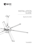
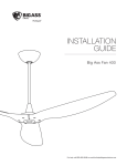
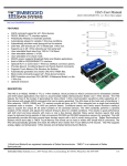
See page 13 for mounting
instructions.
See page 12 for mounting
instructions.
WWW.BIGASSFANS.COM
Bar Joists
I-Beam
©2012 DELTA T CORP.
See complete instructions
included with the L-Bracket
Installation Kit.
Solid Beam
DBA BIG ASS )$1&2$//5,*+765(6(59('
See complete instructions
included with the Z-Purlin
Installation Kit.
Z-Purlins
See complete instructions
included with the Compound
Angle Mount Installation Kit.
I-Beam (Angled)
The following is intended as a reference guide for Powerfoil®X 2.0 Washdown and Powerfoil®X2.0Plus Washdown fan mounting methods. See the referenced pages for complete fan
installation and operating instructions. Consult a structural engineer to determine which mounting method best suits your building structure.
Mounting Reference Guide
8’–24’ POWERFOIL®;:$6+'2:132:(5)2,/®X2.0PLUS WASHDOWN
8’–24’ POWERFOIL®X2.0 WASHDOWN & POWERFOIL®X2.0PLUS WASHDOWN
Contents
Introduction
Safety Instructions
Mounting Reference Guide
Thank You
About Big Ass Fans
About the Fan
7HFKQLFDO6SHFL¿FDWLRQV
Pre-Installation
What’s in the Box
Parts and Hardware
Tools Needed
Understanding Roof Pitch
Fan Diagram
Controller Diagram
Preparing the Work Site
8QGHUVWDQGLQJ$LUÀRZ3DWWHUQV
4
5
6
6
7
8
9
10
Mounting Structure:
I-Beam
Attach Upper Yoke (to I-Beam)
12
Mounting Structure:
Bar Joists
1. Select Proper Angle Irons
2. Pre-drill Angle Irons
3. Secure Angle Irons (span is longer than 8 ft)
4a. Fasten Single Angle Irons to Roof Structure
4b. Fasten Double Angle Irons to Roof Structure
5a. Attach Upper Yoke (to Angle Irons)
5b. Attach Main Fan Unit (to Angle Irons)
13
14
14
15
16
17
18
Hanging the Fan
1. Attach Extension Tube (to Upper Yoke)
2. Secure Upper Safety Cable
3. Attach Lower Yoke (to Extension Tube)
4. Attach Main Fan Unit (to Lower Yoke)
&RQ¿UP2ULHQWDWLRQ
19
19
20
20
20
Installing Guy Wires
1. Attach Locking Carabiners to Main Fan Unit
2. Attach Beam Clamp
3. Route Guy Wire through Gripple®
4. Install Remaining Guy Wires
21
21
23
23
Installing Airfoils
1. Attach Winglets to Airfoils
2. Position Airfoils
3. Attach Airfoils to Hub
24
24
25
Electrical Installation
Safety Guidelines
Delta Secondary
Branch Circuit Protection
Mounting the Variable Frequency Drive (VFD)
Wiring: Fan Controller (200V–250V Single-Phase, 1 HP)
Wiring: Fan Controller (200V–250V Single-Phase, 2 HP)
Wiring: Fan Controller (200V–250V Three-Phase, 1 HP & 2 HP)
Wiring: Fan Controller (400V–480V Three-Phase, 1 HP & 2 HP)
Daisy Chaining
%DVLF'LVWULEXWHG,2,QWHUIDFH/2&$/&RQWURO
%DVLF'LVWULEXWHG,2,QWHUIDFH(;7(51$/&RQWURO
,QWHUIDFLQJZLWK%DVLF7LPHUV7KHUPRVWDWVDQG2WKHU(TXLSPHQW
&RQWUROOHU2SHUDWLRQ
Starting, Stopping, and Direction Control
Changing the Fan Speed
Cycling through the LED Display Modes
Toggling the Fan’s Command Source
26
27
28
29
30
31
32
33
34
36
37
38
39
39
39
40
40
WWW.BIGASSFANS.COM
©2012 DELTA T CORP.
DBA BIG ASS FAN CO.
ii
iii
1
1
1
2
ALL RIGHTS RESERVED
8’–24’ POWERFOIL®X2.0 WASHDOWN & POWERFOIL®X2.0PLUS WASHDOWN
Contents (cont.)
Electrical Installation
(cont.)
Understanding and Clearing Fan Faults
Programming and Parameter Changes
Locking and Unlocking Procedures
41
41
42
Operating the Fan
Heating Season
Cooling Season
44
44
Preventive Maintenance
Annual Preventive Maintenance
General Preventive Maintenance
Annual Maintenance Checklist
45
45
47
Troubleshooting
General Troubleshooting
E Series Fan Error Codes
M Series Fan Error Codes
49
50
52
Warranty Return
Instructions
Return Instructions
Warranty Claim Form Instructions
Warranty Claim Form
Responsibility Agreement
54
55
57
58
Big Ass )DQ&HUWL¿HG
Installers
Check-In Procedure
&ORVH2XW3URFHGXUH
59
61
WWW.BIGASSFANS.COM
©2012 DELTA T CORP.
DBA BIG ASS FAN CO.
ALL RIGHTS RESERVED
8’–24’ POWERFOIL®X2.0 WASHDOWN & POWERFOIL®X2.0PLUS WASHDOWN
Introduction
1
7KDQN\RXDQGFRQJUDWXODWLRQVRQ\RXUSXUFKDVHRID%LJAss )DQDQHI¿FLHQWDQGFRVWHIIHFWLYHZD\WRVWD\FRROLQWKHVXPPHUDQG
ZDUPLQWKHZLQWHU7KHUHYROXWLRQDU\GHVLJQRIRXUIDQVFRPELQHVWKHEHVWRIERWKIRUPDQGIXQFWLRQWREULQJSRZHUSHUIRUPDQFHDQGD
VOHHNORRNWRDQ\VHWWLQJ0RUHLPSRUWDQWO\\RXKDYHSXUFKDVHGDSURGXFWWKDWLVEDFNHGE\H[WHQVLYHUHVHDUFKWKRURXJKWHVWLQJDQG
TXDOLW\PDQXIDFWXULQJ:H¶UHUHDG\WRDQVZHUDQ\TXHVWLRQVRUFRPPHQWVDW%,*)$16RUYLVLWRXU:HEVLWHDW
ZZZELJassIDQVFRP
Who we are and what we do
%LJAss )DQVKDVEHHQWKHSUHHPLQHQWPDQXIDFWXUHURIODUJHGLDPHWHUORZVSHHGIDQVVLQFH:LWKDZRUOGZLGHSUHVHQFHDQG
ORFDWHGLQEHDXWLIXO/H[LQJWRQ.<ZHUHVHDUFKGHVLJQDQGPDQXIDFWXUHWKHPRVWHIIHFWLYHDLUPRYHPHQWVROXWLRQVRQWKHPDUNHW
2XUQHYHUHQGLQJFRPPLWPHQWWRTXDOLW\DQGLQQRYDWLRQNHHSVXVDWWKHOHDGLQJHGJHRIDEXUJHRQLQJLQGXVWU\:LWKDQH\HWRKHOSLQJ
FXVWRPHUVVDWLVI\WKHLUQHHGVDQGDVWURQJVHQVHRIFRUSRUDWHUHVSRQVLELOLW\WRWKHFRPPXQLW\%LJAss )DQVKDVUHGH¿QHGWKHZD\
EXVLQHVVLVGRQH
About the fan
The Powerfoil®;:DVKGRZQLVWKH¿UVWDQGRQO\IDQRILWVNLQGGHYHORSHGLQGLUHFWUHVSRQVHWRUHTXHVWVIURPIRRGPDQXIDFWXUHUV
IRUDQDLUPRYHPHQWVROXWLRQWKDWZRXOGPHHWWKHQHHGVRIWKHVWULFWHVWIRRGSURFHVVLQJIDFLOLWLHV)HDWXUHVDQGEHQH¿WVRIWKH
3RZHUIRLO;:DVKGRZQLQFOXGH
•
•
•
•
•
6WDLQOHVVVWHHODQGDOXPLQXPFRPSRQHQWV
6WDLQOHVVVWHHOZDVKGRZQPRWRUIRUIUHTXHQWLQWHQVHFOHDQLQJ
)RRGGXW\HSR[\
&RPSOHWHO\VHDOHG1LWUR6HDOJHDUER[ZLWKIRRGJUDGHRLO
1RQSRURXVQRQDEVRUEHQWDQGFRUURVLRQUHVLVWDQWPDWHULDOV
WWW.BIGASSFANS.COM
©2012 DELTA T CORP.
DBA BIG ASS FAN CO.
ALL RIGHTS RESERVED
8’–24’ POWERFOIL®X2.0 WASHDOWN & POWERFOIL®X2.0PLUS WASHDOWN
,QWURGXFWLRQFRQW
2
Powerfoil®;VSHFL¿FDWLRQV
Fan size
Motor size,
HP (kW)
Minimum required
supply circuit size
Nominal
output
YROWDJHĭ1
Maximum full load
motor current
(as programmed)2
Max
RPM
Airfoil
length
Suggested
distance from
ceiling3
IW
P
$#±9ĭ
$#±9ĭ
$#±9ĭ
$#±9ĭ
9
9
9
9
±$
±$
±$
±$
530
LQ
P
IWP
IW
P
$#±9ĭ
$#±9ĭ
$#±9ĭ
$#±9ĭ
9
9
9
9
±$
±$
±$
±$
530
LQ
P
IWP
IW
P
$#±9ĭ
$#±9ĭ
$#±9ĭ
$#±9ĭ
9
9
9
9
±$
±$
±$
±$
530
LQ
P
IWP
IW
P
$#±9ĭ
$#±9ĭ
$#±9ĭ
$#±9ĭ
9
9
9
9
±$
±$
±$
±$
530
LQ
P
IWP
IW
P
$#±9ĭ
$#±9ĭ
$#±9ĭ
$#±9ĭ
9
9
9
9
±$
±$
±$
±$
530
LQ
P
IWP
IW
P
$#±9ĭ
$#±9ĭ
$#±9ĭ
$#±9ĭ
9
9
9
9
±$
±$
±$
±$
530
LQ
P
IWP
20 ft
P
2.0
$#±9ĭ
$#±9ĭ
$#±9ĭ
$#±9ĭ
9
9
9
9
±$
±$
±$
±$
530
LQ
P
IWP
IW
P
2.0
$#±9ĭ
$#±9ĭ
$#±9ĭ
$#±9ĭ
9
9
9
9
±$
±$
±$
±$
530
LQ
P
IWP
2XWSXWYROWDJHZLOOQRWH[FHHG,QSXWYROWDJHZLWKWKHH[FHSWLRQRI9PRGHOV$OOFRQWUROOHUVSURGXFHĭRXWSXWSRZHUUHJDUGOHVVRILQSXWSKDVH
2. 7KLVYDOXHPD\YDU\GXHWRLQSXWYROWDJHFRQGLWLRQV
7KHGLVWDQFHRIWKHIDQIURPWKHFHLOLQJVKRXOGEHPHDVXUHGIURPWKHWRSRIWKHZLQJOHWVWRWKHFHLOLQJ
CAUTION: Big Ass Fans requires that the Powerfoil X2.0 fan be supplied from one of the following types of transformers:
575V–600V models: 575V/330V Wye secondary (neutral not utilized)
400V–480V models: 480V/277V Wye secondary (neutral not utilized)
200V–250V models: 208V/120V Wye secondary (neutral not utilized)
240V/120V Delta secondary (Wild/High Phase B)
Integration into any other power distribution scheme may result in improper fan operation or premature hardware failure! See
page 26 for more information.
WWW.BIGASSFANS.COM
©2012 DELTA T CORP.
DBA BIG ASS FAN CO.
ALL RIGHTS RESERVED
8’–24’ POWERFOIL®X2.0 WASHDOWN & POWERFOIL®X2.0PLUS WASHDOWN
,QWURGXFWLRQFRQW
3
Powerfoil®;3OXVVSHFL¿FDWLRQV
Fan size
Motor size,
HP (kW)
Minimum required supply
circuit size
Nominal output
YROWDJHĭ1
Maximum full load
motor current
(as programmed)2
Max RPM
Airfoil
length
Suggested
distance from
ceiling3
IW
P
$#±9ĭ
$#±9ĭ
$#±9ĭ
$#±9ĭ
9
9
9
9
±$
±$
±$
±$
530
LQ
P
IWP
IW
P
$#±9ĭ
$#±9ĭ
$#±9ĭ
$#±9ĭ
9
9
9
9
±$
±$
±$
±$
530
LQ
P
IWP
IW
P
$#±9ĭ
$#±9ĭ
$#±9ĭ
$#±9ĭ
9
9
9
9
±$
±$
±$
±$
530
LQ
P
IWP
IW
P
$#±9ĭ
$#±9ĭ
$#±9ĭ
$#±9ĭ
9
9
9
9
±$
±$
±$
±$
530
LQ
P
IWP
IW
P
$#±9ĭ
$#±9ĭ
$#±9ĭ
$#±9ĭ
9
9
9
9
±$
±$
±$
±$
530
LQ
P
IWP
20 ft
P
2.0
$#±9ĭ
$#±9ĭ
$#±9ĭ
$#±9ĭ
9
9
9
9
±$
±$
±$
±$
530
LQ
P
IWP
IW
P
2.0
$#±9ĭ
$#±9ĭ
$#±9ĭ
$#±9ĭ
9
9
9
9
±$
±$
±$
±$
530
LQ
P
IWP
2XWSXWYROWDJHZLOOQRWH[FHHG,QSXWYROWDJHZLWKWKHH[FHSWLRQRI9PRGHOV$OOFRQWUROOHUVSURGXFHĭRXWSXWSRZHUUHJDUGOHVVRILQSXWSKDVH
2. 7KLVYDOXHPD\YDU\GXHWRLQSXWYROWDJHFRQGLWLRQV
7KHGLVWDQFHRIWKHIDQIURPWKHFHLOLQJVKRXOGEHPHDVXUHGIURPWKHWRSRIWKHZLQJOHWVWRWKHFHLOLQJ
CAUTION: Big Ass Fans requires that the Powerfoil X2.0 Plus fan be supplied from one of the following types of
transformers:
575V–600V models: 575V/330V Wye secondary (neutral not utilized)
400V–480V models: 480V/277V Wye secondary (neutral not utilized)
200V–250V models: 208V/120V Wye secondary (neutral not utilized)
240V/120V Delta secondary (Wild/High Phase B)
Integration into any other power distribution scheme may result in improper fan operation or premature hardware failure! See
page 26 for more information.
WWW.BIGASSFANS.COM
©2012 DELTA T CORP.
DBA BIG ASS FAN CO.
ALL RIGHTS RESERVED
8’–24’ POWERFOIL®X2.0 WASHDOWN & POWERFOIL®X2.0PLUS WASHDOWN
4
Pre-Installation
What’s in the box
If you ordered multiple fans, be sure to keep the components of each fan together. The fans each have differently rated
components that are not interchangeable.
7KHIDQLVVKLSSHGLQPXOWLSOHER[HV5HIHUWRWKHLOOXVWUDWLRQVEHORZ,IWKHH[WHQVLRQWXEHLVIWRUORQJHULWZLOOEHVKLSSHGLQD
VHSDUDWHER[$OODFFHVVRULHVDUHVKLSSHGLQVHSDUDWHER[HV7KLVLQVWDOODWLRQJXLGHVKRXOGUHPDLQZLWKWKHRZQHURIWKHIDQ
Note: Dashed lines indicate internal boxes. The drawings below are not to scale.
%HDP&OLS
6SDFHU
8SSHU<RNH
/RZHU<RNH
:LQJOHW
+DUGZDUH
%RDUGV
Main Box
9DULDEOH)UHTXHQF\'ULYH
ZLWK&RQWUROOHU.H\SDG
0DLQ)DQ8QLW
Extension Tube Box
Airfoil Box
([WHQVLRQ7XEH
6DIHW\&DEOH
$LUIRLO2
Powerfoil®ZLQJOHWVKRZQ3RZHUIRLORU3RZHUIRLO3OXVZLQJOHWVDUHDYDLODEOH
2. $LUIRLOUHWDLQHUVDUHSDFNHGLQDEDJZLWKWKH,QVWDOODWLRQ*XLGH
7KHVDIHW\FDEOHLVDWWDFKHGWRWKHH[WHQVLRQWXEH,IWKHH[WHQVLRQWXEHLVIWRUORQJHULWZLOOEHVKLSSHGLQDVHSDUDWHER[*X\ZLUHVLIRUGHUHG
DUHEDJJHGVHSDUDWHO\LQPDLQER[
WWW.BIGASSFANS.COM
©2012 DELTA T CORP.
DBA BIG ASS FAN CO.
ALL RIGHTS RESERVED
8’–24’ POWERFOIL®X2.0 WASHDOWN & POWERFOIL®X2.0PLUS WASHDOWN
3UH,QVWDOODWLRQFRQW
5
Parts and hardware
Note: The drawings below are not to scale. No hardware substitutions are acceptable.
Hardware
Upper Yoke Hardware
[´*5%ROW
´)ODW:DVKHU
1\ORFN1XW
Extension Tube Hardware
[´*5%ROW
´)ODW:DVKHU
1\ORFN1XW
Lower Yoke Hardware
[´*5%ROW
´)ODW:DVKHU
1\ORFN1XW
Winglet Hardware
[´%ROW
[´%DUUHO
Airfoil Hardware
[´*5%ROW
´)ODW:DVKHU
1\ORFN1XW
Main Fan Unit Hardware
[´*5%ROW
´)ODW:DVKHU
1\ORFN1XW
Guy Wire Hardware
/RFNLQJ&DUDELQHU
´%HDP&OLS
[´(\HEROW
+H[1XW
*ULSSOH®
*X\:LUH
:LUH5RSH&OLS
Mounting
%HDP&OLS
6SDFHU
Airfoils
/RZHU<RNH
8SSHU<RNH2
$LUIRLOV
or
3RZHUIRLO®
:LQJOHWV
([WHQVLRQ7XEH
6DIHW\&DEOH4
6KDFNOH6
0DLQ)DQ8QLW+XE&RYHU
3RZHUIRLO®3OXV
:LQJOHWV
$LUIRLO5HWDLQHUV
Electrical
9DULDEOH)UHTXHQF\'ULYH
9)'ZLWK.H\SDG
*X\ZLUHVDUHGHVLJQHGWRFRQVWUDLQIDQ¶VODWHUDOPRYHPHQWDQGDUHRQO\LQFOXGHGLQVRPHIDQ
SDFNDJHV%LJAss )DQVUHFRPPHQGVXVLQJJX\ZLUHVLIWKHIDQ¶VH[WHQVLRQWXEHLVIWRUORQJHULI
WKHIDQLVH[SRVHGWRKLJKZLQGVRUVLPLODUFRQGLWLRQVRULIWKHIDQLVFORVHWRDQ\EXLOGLQJ¿[WXUHV
*X\:LUHKDUGZDUHLVEDJJHGVHSDUDWHO\IURPKDUGZDUHERDUGV
2. (QVXUH\RXKDYHWKHFRUUHFWXSSHU\RNHIRU\RXUPRXQWLQJPHWKRG7KHXSSHU\RNHPD\GLIIHUIURP
WKHLOOXVWUDWLRQ
3RZHUIRLOZLQJOHWVDUHVWDQGDUG3RZHUIRLO3OXVZLQJOHWVDUHRQO\LQFOXGHGLIRUGHUHG
6DIHW\FDEOHLVDWWDFKHGWRH[WHQVLRQWXEH
6KDFNOHLQFOXGHGRQKDUGZDUHERDUGV
WWW.BIGASSFANS.COM
©2012 DELTA T CORP.
DBA BIG ASS FAN CO.
ALL RIGHTS RESERVED
8’–24’ POWERFOIL®X2.0 WASHDOWN & POWERFOIL®X2.0PLUS WASHDOWN
3UH,QVWDOODWLRQFRQW
6
Tools needed
%LJAss )DQVUHFRPPHQGVJDWKHULQJWKHIROORZLQJWRROVSULRUWREHJLQQLQJLQVWDOODWLRQNote: This list of suggested tools is not
exhaustive. Additional tools may be necessary.
Mechanical installation
Electrical installation
6WDQGDUGZUHQFKVHW
3KLOOLSVDQGÀDWKHDGVFUHZGULYHU
6WDQGDUGVRFNHWVHWZLWKUDWFKHW
´QXWGULYHU
7RUTXHZUHQFKFDSDEOHRIIWÂOE1ÂP
´QXWGULYHU
3KLOOLSVDQGÀDWKHDGVFUHZGULYHU
3DLURIWR$:*VWULSSHUV
6WDQGDUGDOOHQZUHQFKVHW
3DLURIPHGLXPFKDQQHOORFNV
0XOWLPHWHU
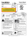
Understanding roof pitch
%HIRUHEHJLQQLQJLQVWDOODWLRQFRQ¿UPWKDW\RXKDYHWKHDSSURSULDWHPRXQWIRU\RXUURRISLWFK
7RHQVXUHWKHIDQLVSURSHUO\PRXQWHGWKHIDQPXVWDOZD\VKDQJSOXPEWRWKHJURXQGDQGWKH\RNHPXVWEHLQVWDOOHGXVLQJWKHEROW
KROHVDWWKHZLGHVWORFDWLRQVSRVVLEOH7RDFFRPPRGDWHEXLOGLQJVWUXFWXUHVRQZKLFKWKHVWDQGDUGXSSHU\RNHGRHVQRWDOORZWKHIDQWR
SURSHUO\RULHQWLWVHOIWKH'HJUHH2IIVHWPRXQWVKRXOGEHSXUFKDVHG
7KHH[DPSOHEHORZVKRZVRQHVLWXDWLRQLQZKLFKWKH'HJUHH2IIVHWPRXQWPXVWEHXVHGVRWKDWWKHIDQKDQJVSOXPEWRWKHJURXQG
DQGWKHZLGHVWVWDQFHIRUWKHXSSHU\RNHLVHQVXUHG,I\RXDUHXQFHUWDLQRI\RXUURRISLWFKRUGRQRWKDYHWKHFRUUHFWPRXQWWRSURSHUO\
KDQJ\RXUIDQFRQVXOWDVWUXFWXUDOHQJLQHHURUFRQWDFW%LJAss )DQV&XVWRPHU6HUYLFHDW%,*)$16
Standard Upper Yoke
WWW.BIGASSFANS.COM
©2012 DELTA T CORP.
90-Degree Offset Mount
DBA BIG ASS FAN CO.
ALL RIGHTS RESERVED
8’–24’ POWERFOIL®X2.0 WASHDOWN & POWERFOIL®X2.0PLUS WASHDOWN
3UH,QVWDOODWLRQFRQW
7
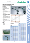
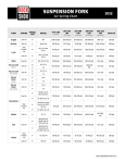
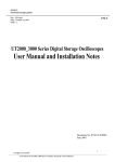
Fan diagram
A. Safety Cable. $UHGXQGDQWVDIHW\IHDWXUHWKDWVHFXUHVWKHIDQWRWKH
PRXQWLQJVWUXFWXUH
B. Upper Yoke.6HFXUHVWKHIDQWRWKHPRXQWLQJVWUXFWXUHDQGDOORZVWKHIDQ
WRDGMXVWLWVFHQWHURIJUDYLW\
C. Extension Tube. ([WHQGVWKHIDQIURPWKHFHLOLQJ
D. Lower Yoke. &RQQHFWVWKHPDLQIDQDVVHPEO\WRWKHH[WHQVLRQWXEH
A
E. VFD Enclosure (not shown). &RQWDLQVWKHYDULDEOHIUHTXHQF\GULYHZLWK
WKHFRQWUROOHUNH\SDGPRXQWHGRQWKHIURQWRIWKHHQFORVXUH
F. Gearbox. 1LWUR6HDO'ULYH™FXVWRPJHDUER[IRULQFUHDVHGGXUDELOLW\DQG
FRROHURSHUDWLRQ
B
G. Motor. 6HHSDJHV±IRUPRUHLQIRUPDWLRQ
H. Hub.6HFXUHVWKHDLUIRLOVWRWKHJHDUER[RXWSXWVKDIW
I. Airfoil. 3URYLGHVDLUPRYHPHQW7KHXQLTXHSDWHQWHGGHVLJQSURYLGHV
HI¿FLHQWDQGHIIHFWLYHDLUPRYHPHQW
J. Winglet (Powerfoil® [shown] or Powerfoil®Plus). ,PSURYHVWKHHI¿FLHQF\
DQGSHUIRUPDQFHRIWKHIDQ
C
D
G
F
H
I
J
WWW.BIGASSFANS.COM
©2012 DELTA T CORP.
DBA BIG ASS FAN CO.
ALL RIGHTS RESERVED
8’–24’ POWERFOIL®X2.0 WASHDOWN & POWERFOIL®X2.0PLUS WASHDOWN
3UH,QVWDOODWLRQFRQW
8
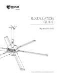
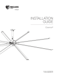
Controller diagram
Note: The illustration below does not show wiring.
VFD Enclosure (Front View)
A. Controller Keypad. &RQWUROVIDQRSHUDWLRQ
B. Disconnect.(PHUJHQF\GLVFRQQHFWIRUWKHIDQFRQWUROOHU7KH
VZLWFKPXVWEHXVHGWRGLVFRQQHFWSRZHUZKHQVHUYLFLQJWKH
9)'RURWKHUHOHFWULFDOFRPSRQHQWV
A
C. Variable Frequency Drive (VFD). 7KH9)'FRQWUROV$&SRZHU
WRWKHPRWRU
B
D. Fire Relay. 6KXWGRZQUHOD\IRU¿UHFRQWUROSDQHOLQWHJUDWLRQ
E. Fuses.3URWHFWVWKHV\VWHPDJDLQVWSRZHUVXUJHVDQG
RYHUFXUUHQW
F. Category 5 Cable and Connector.'DWDFDEOHEHWZHHQWKH
FRQWUROOHUNH\SDGDQGWKH9)'
VFD Enclosure (Inner View)
B
F
E
C
D
WWW.BIGASSFANS.COM
©2012 DELTA T CORP.
DBA BIG ASS FAN CO.
ALL RIGHTS RESERVED
8’–24’ POWERFOIL®X2.0 WASHDOWN & POWERFOIL®X2.0PLUS WASHDOWN
3UH,QVWDOODWLRQFRQW
9
Preparing the work site
%HIRUHEHJLQQLQJLQVWDOODWLRQUHYLHZWKHPHFKDQLFDODQGHOHFWULFDOLQVWDOODWLRQJXLGHOLQHVEHORZ
Mechanical installation
• $IWP3RZHUIRLO®; IDQZHLJKVDWPD[LPXPOEVNJ$VXLWDEOHPHDQVIRUOLIWLQJWKHZHLJKWRIWKHIDQVXFKDVD
VFLVVRUOLIWDQGDWOHDVWWZRLQVWDOODWLRQSHUVRQQHOZLOOEHUHTXLUHG
• %LJAss )DQVFDQRQO\EHPRXQWHGWRDQ,EHDPRUDQJOHLURQV,IPRXQWLQJWRDQ,EHDPWKH,EHDPPXVWEHSDUWRIWKHH[LVWLQJ
EXLOGLQJVWUXFWXUH'RQRWPRXQWWKHIDQWRDVLQJOHSXUOLQWUXVVRUEDUMRLVW&RQVXOWDVWUXFWXUDOHQJLQHHUIRULQVWDOODWLRQPHWKRGVQRW
FRYHUHGLQWKHJXLGH
I-Beam
Angle Iron
• 7KHPRXQWLQJVWUXFWXUHPXVWEHDEOHWRZLWKVWDQGWKHWRUTXHIRUFHVJHQHUDWHGE\WKHIDQ$IWIDQJHQHUDWHVQHDUO\IWÂOE
1ÂPRIWRUTXHGXULQJRSHUDWLRQ
• )DQVPRXQWHGRQIDEULFDWHG,EHDPVZKLFKDUHFRPPRQLQVWHHOEXLOGLQJVFRXOGFDXVHWKHEHDPWRÀH[DQGWKHIDQWRPRYH
VLJQL¿FDQWO\GXULQJRSHUDWLRQ,IWKLVÀH[LQJFDXVHVDFOHDUDQFHSUREOHPZHVXJJHVWLQVWDOOLQJWKH,%HDP6WDELOL]HUNLW
• ,IWKHIDQ¶VH[WHQVLRQWXEHLVIWPRUORQJHURULIWKHPRXQWLQJVWUXFWXUHUHTXLUHVLWWKHIDQ¶VODWHUDOPRYHPHQWPXVWEHVHFXUHG
XVLQJJX\ZLUHV,IWKHIDQLVFORVHWRDQ\EXLOGLQJ¿[WXUHVLWLVUHFRPPHQGHGWRVHFXUHWKHIDQZLWKJX\ZLUHVDVDVDIHW\PHDVXUH
• $GKHUHWRWKHVDIHW\UHTXLUHPHQWVLQWKHWDEOHEHORZZKHQVHOHFWLQJZKHUHWRPRXQWWKHIDQ
Safety requirement
Minimum distances
&OHDUDQFH
IWIURPDOOIDQSDUWV7KHIDQLQVWDOODWLRQDUHDPXVWEHIUHHRIREVWUXFWLRQVVXFKDVOLJKWVFDEOHV
VSULQNOHUVRURWKHUEXLOGLQJVWUXFWXUH6HHWKHWDEOHVRQSS±IRUUHFRPPHQGHGPLQLPXPFHLOLQJ
FOHDUDQFHV
$LUIRLOKHLJKW
IWDERYHWKHIORRU
+9$&HTXLSPHQW
[IDQGLDPHWHULIDERYHGLIIXVHU[IDQGLDPHWHULIEHORZGLIIXVHU5HIHUWRWKHLOOXVWUDWLRQEHORZ
)DQVSDFLQJ
[IDQGLDPHWHUFHQWHUWRFHQWHU
5DGLDQW,5KHDWHUV
6HHWKHPDQXIDFWXUHU¶VUHTXLUHPHQWVIRUWKHPLQLPXPFOHDUDQFHWRFRPEXVWLEOHV
,IWKHIDQLVPRXQWHGDWWKHVDPHOHYHO
RUKLJKHUWKDQDGLIIXVHUWKHZLQJOHWV
PXVWEHDWDGLVWDQFHWKDWLVDWOHDVW
[WKHPHDVXUHRIWKHIDQ¶VGLDPHWHU
HVAC
Diffuser
[IDQ¶VGLDPHWHU
IW
IWGLDPHWHU
,IWKHIDQLVPRXQWHGEHORZD
GLIIXVHUWKHZLQJOHWVPXVWEHDW
DGLVWDQFHWKDWLVDWOHDVW[WKH
PHDVXUHRIWKHIDQ¶VGLDPHWHU
HVAC
Diffuser
[IDQ¶VGLDPHWHU
IW
IWGLDPHWHU
Electrical installation
• 7RUHGXFHWKHULVNRIHOHFWULFVKRFNZLULQJVKRXOGEHSHUIRUPHGE\DTXDOL¿HGHOHFWULFLDQ,QFRUUHFWDVVHPEO\FDQFDXVHHOHFWULF
VKRFNRUGDPDJHWKHPRWRUDQGWKHFRQWUROOHU
• 7KHLQVWDOODWLRQRID%LJAss )DQPXVWEHLQDFFRUGDQFHZLWKWKH1DWLRQDO(OHFWULFDO&RGH1(&$16,1)3$DQGDOOORFDO
FRGHV
• $&VXSSO\IHHGVIRURQHIDQFRQWUROOHUPD\VKDUHWKHVDPHFRQGXLWZLWK$&VXSSO\IHHGVIRURQHRUPRUHFRQWUROOHUV
• $OOXQXVHGFRQGXFWRUVWKDWVKDUHDFRQGXLWZLWKWKH$&VXSSO\IHHGVPXVWEHJURXQGHGRQERWKHQGV
• ,IUHTXLUHGDORFDOGLVFRQQHFWVKRXOGEHLQVWDOOHGSHU1(&DQGDOOORFDOFRGHV
• 5HIHUWRVSHFL¿FDWLRQVRQSDJHV±IRUDSSURSULDWHFLUFXLWUHTXLUHPHQWV
• (DFKIDQUHTXLUHVGHGLFDWHGEUDQFKFLUFXLWSURWHFWLRQ
• 7RDYRLGGDPDJHWRWKH9)'DQGIDQFRQWUROOHUWHVWWKH9)'DQGIDQFRQWUROOHUZLWKDWHVWFDEOHEHIRUHZLULQJWKH&$7FDEOH
WWW.BIGASSFANS.COM
©2012 DELTA T CORP.
DBA BIG ASS FAN CO.
ALL RIGHTS RESERVED
8’–24’ POWERFOIL®X2.0 WASHDOWN & POWERFOIL®X2.0PLUS WASHDOWN
3UH,QVWDOODWLRQFRQW
10
8QGHUVWDQGLQJDLUÀRZSDWWHUQV
$LUÀRZLQDQRSHQDUHD
7KHDLUÀRZPRYHVIURPWKHIDQWRZDUGWKHÀRRU
2QFHDLUÀRZKLWVWKHÀRRULWPRYHVRXWZDUGLQ
DOOGLUHFWLRQV7KHGHÀHFWLRQRIDLURIIWKHÀRRULV
FDOOHGD³ÀRRUMHW´
$LUÀRZLQDQHQFORVHGDUHD
7KHÀRRUMHWUDGLDWHVRXWZDUGXQWLOLWUHDFKHVWKH
ZDOOVZKLFKGHÀHFWWKHMHWXSZDUG$IWHULWKLWV
WKHFHLOLQJWKHXSZDUGÀRZLVGLUHFWHGLQZDUG
WRWKHORZSUHVVXUHDUHDDERYHWKHIDQZKHUH
LWLVWKHQSXOOHGGRZQWRZDUGWKHÀRRU7KLV
FUHDWHVDFRQYHFWLRQOLNHDLUFXUUHQWWKDWJDWKHUV
PRPHQWXP2QFHWKLVFXUUHQWLVHVWDEOLVKHG
WKHIDQEHJLQVWRPRYHDLURXWVLGHRIWKH
FXUUHQWHVFDODWLQJLWVFRROLQJHIIHFWV
$LUÀRZZLWKPXOWLSOHIDQV
:KHUHWKHUHDUHPXOWLSOHIDQVDSSURSULDWHO\
VSDFHGWKHH[SDQGLQJMHWVRIDGMDFHQWIDQV
PHHWWRFUHDWHDSUHVVXUH]RQH7KHSUHVVXUH
]RQHDFWVOLNHDZDOOFDXVLQJHDFKIDQWR
EHKDYHOLNHDVLQJOHHQFORVHGIDQ7\SLFDOO\
DVLQJOHIDQ¶VSHUIRUPDQFHZLOOLQFUHDVHZKHQ
ZRUNLQJLQFRQMXQFWLRQZLWKRWKHUIDQV
$LUÀRZZLWKVWUHDPOLQHGREVWUXFWLRQ
Overhead View
2EVWUXFWLRQVRQWKHÀRRUWHQGWREORFNWKH
KRUL]RQWDOO\PRYLQJDLU7KLQRUVWUHDPOLQHG
REVWUXFWLRQVGRQRWEORFNPXFKDLUÀRZ
UHJDUGOHVVRIVL]H7KHDLUWHQGVWRÀRZ
VPRRWKO\DURXQGWKHVHREVWUXFWLRQVORVLQJOLWWOH
PRPHQWXPDQGOHDYLQJRQO\DVPDOOVWDJQDQW
DUHDEHKLQGWKHREVWUXFWLRQ
Side View
$LUÀRZZLWKZLGHEOXQWREVWUXFWLRQ
$ZLGHEOXQWRUÀDWIDFHGREVWUXFWLRQIRUFHV
DLUÀRZWRFKDQJHGLUHFWLRQWXUQLQJLWXSZDUG
DQGRXWZDUG7KHUHLVDVWDJQDQWDUHDEHKLQG
WKHVHREVWUXFWLRQVWKDWLVZLGHUDQGKLJKHUWKDQ
WKHREVWUXFWLRQVWKHPVHOYHV
WWW.BIGASSFANS.COM
©2012 DELTA T CORP.
DBA BIG ASS FAN CO.
ALL RIGHTS RESERVED
8’–24’ POWERFOIL®X2.0 WASHDOWN & POWERFOIL®X2.0PLUS WASHDOWN
3UH,QVWDOODWLRQFRQW
11
Powerfoil® X2.0Plus
7KH3RZHUIRLO 3OXVZLQJOHWFUHDWHVDMHWRIDLUWKDWÀRZVRXWZDUGDWDDQJOHSDVVLQJRYHUÀRRUREVWUXFWLRQVDQGGHOLYHULQJ
DLUÀRZLQDPXFKEURDGHUSDWWHUQ:KHQSODQQLQJIDQSODFHPHQWFRQVLGHUWKH3RZHUIRLO; 3OXVIDQ¶VODUJHUFRYHUDJHDUHDNote:
Powerfoil Plus winglets are optional and may not be included in your fan order.
Tips
%HORZDUHVRPHWHFKQLTXHVWKDWFDQPDNHDGUDPDWLFGLIIHUHQFHLQFRQJHVWHGDUHDVRI\RXUIDFLOLW\7UHDWDLUOLNHZDWHUDQGVFRRS
GLUHFWDQGFKDQQHOLWWRZKHUHLWLVQHHGHGPRVWNote: Powerfoil X 2.0Plus fans deliver air from a much higher angle, resolving many of
the issues outlined below.
• 0DNHVXUHSHRSOHDUHQRWKLGGHQEHKLQGVWUXFWXUHVWKDWZRXOGEORFNDLUÀRZ7KLVPD\VHHPREYLRXVEXWZRUNDUHDVDUHURXWLQHO\
EORFNHGE\VKHOYLQJFUDWHVDQGPDFKLQHU\
• 3RVLWLRQODUJHREVWUXFWLRQVVRWKDWWKHLUVPDOOHVWSUR¿OHVDUHSHUSHQGLFXODUWRWKHGLUHFWLRQRIDLUPRYHPHQW)RUH[DPSOHDVKHHW
PHWDOSUHVVEUDNHPLJKWKDYH¿YHWLPHVWKHIURQWDODUHDLILWLVIDFLQJWKHDLUÀRZUDWKHUWKDQLILWLVWXUQHGVLGHZD\V
• :KHUHYHUSRVVLEOHSRVLWLRQZHOGLQJFXUWDLQVSDUWLWLRQVVKHHWPDWHULDOVHWFWRVFRRSDLULQWRWKHZRUNDUHDUDWKHUWKDQGHÀHFWLW
• 7DNHDGYDQWDJHRIWKHDLUPRYLQJQHDUWKHÀRRUE\FUHDWLQJJURXQGOHYHORSHQLQJVLQ\RXUZRUNDUHD,WLVEHWWHUWRKDYHDZRUNDUHD
EORFNHGE\PDWHULDOVVWDFNHGWRWKHFHLOLQJZLWKDQRSHQLQJEHORZWKDQWRKDYHORZVWDFNVIWPWRIWPKLJKVLWWLQJRQ
WKHÀRRU
WWW.BIGASSFANS.COM
©2012 DELTA T CORP.
DBA BIG ASS FAN CO.
ALL RIGHTS RESERVED
8’–24’ POWERFOIL®X2.0 WASHDOWN & POWERFOIL®X2.0PLUS WASHDOWN
12
Mounting Structure: I-Beam
Big Ass Fans can only be hung from an I-beam or bar joists. See the following page for bar joist mounting instructions.
Consult a structural engineer for installation methods not covered in this manual.
WARNING: The fan should not be installed unless the structure on which the fan is to be mounted is of sound
construction, undamaged, and capable of supporting the loads of the fan and its method of mounting. A structural
engineer should verify that the structure is adequate prior to fan installation. Verifying the stability of the mounting
structure is the sole responsibility of the customer and/or end user, and Big Ass Fans hereby expressly disclaims any
liability arising therefrom, or arising from the use of any materials or hardware other than those supplied by Big Ass Fans
RURWKHUZLVHVSHFL¿HGLQWKHVHLQVWDOODWLRQLQVWUXFWLRQV
CAUTION: It is not recommended to mount a Big Ass Fan to a fabricated I-beam. The I-beam on which the fan will mount
must be part of the existing building structure. Do not direct mount the fan to an I-beam.
&$87,21,QVWDOOWKHVSDFHUVRQO\LIWKHWKLFNQHVVRIWKH,EHDPÀDQJHH[FHHGV´FP7KHPRXQWLQJKROHVRQWKH
spacer are closer to one edge than the other. Make sure this edge of the spacer is facing the I-beam.
%HIRUHEHJLQQLQJLQVWDOODWLRQFRQ¿UPWKDW\RXKDYHWKHDSSURSULDWHPRXQWIRU\RXUURRISLWFK
$WWDFKXSSHU\RNHWR,EHDP
0HDVXUHWKHÀDQJHZLGWKRIWKH,EHDPIURPZKLFKWKHIDQZLOOEHKXQJ6HOHFWWKHXSSHU\RNHPRXQWLQJKROHVWKDWPDWFKWKHÀDQJH
ZLGWKRIWKH,EHDP
6HFXUHWKHXSSHU\RNHWRWKH,EHDPZLWKWKH8SSHU<RNH+DUGZDUHDVVKRZQ7LJKWHQWKHEROWVWRIWÂOE1ÂP XVLQJDWRUTXH
ZUHQFKDQG´VRFNHW
3URFHHGWR³+DQJLQJWKH)DQ´S
8SSHU<RNH+DUGZDUH%$)6XSSOLHG
D [´*5%ROW
E ¶¶)ODW:DVKHU
F 1\ORFN1XW
G %HDP&OLS
H 6SDFHU
Small Upper Yoke
¶¶PP[´PP
I-beam
ÀDQJHZLGWK
Upper yoke
mounting holes
´PPWR
´PP
,QQHUKROHV
!´PPWR
´PP
0LGGOHKROHV
!´PPWR
´PP
2XWHUKROHV
outer holes
middle holes
inner holes
Large Upper Yoke
¶¶PP[´PP
Upper Yoke
(top view)
I-beam
ÀDQJHZLGWK
Upper yoke
mounting holes
´PPWR
´PP
,QQHUKROHV
!´PPWR
´PP
0LGGOHKROHV
!´PPWR
´PP
2XWHUKROHV
Side View
a
E
G
Spacers are only used if
WKHEHDPÀDQJHH[FHHGV
3/8” (1 cm).
e
E
F
Note: Ensure the spacers are oriented as shown above.
WWW.BIGASSFANS.COM
©2012 DELTA T CORP.
DBA BIG ASS FAN CO.
ALL RIGHTS RESERVED
8’–24’ POWERFOIL®X2.0 WASHDOWN & POWERFOIL®X2.0PLUS WASHDOWN
Mounting Structure: Bar Joists
Big Ass Fans can only be hung from an I-beam or bar joists. See the previous page for I-beam mounting instructions.
Consult a structural engineer for installation methods not covered in this manual.
WARNING: The fan should not be installed unless the structure on which the fan is to be mounted is of sound
construction, undamaged, and capable of supporting the loads of the fan and its method of mounting. A structural
engineer should verify that the structure is adequate prior to fan installation. Verifying the stability of the mounting
structure is the sole responsibility of the customer and/or end user, and Big Ass Fans hereby expressly disclaims any
liability arising therefrom, or arising from the use of any materials or hardware other than those supplied by Big Ass Fans
RURWKHUZLVHVSHFL¿HGLQWKHVHLQVWDOODWLRQLQVWUXFWLRQV
WARNING: Never use beam clips when mounting the fan to angle irons! Beam clips are only intended for I-beam
installations.
CAUTION: Do not install the fan from a single purlin, truss, or bar joist.
&$87,218QVXSSRUWHGDQJOHLURQVSDQVVKRXOGQRWH[FHHGIWP
CAUTION: The angle irons must be fastened to the roof structure at each end.
1. Select proper angle irons
8VLQJWKHWDEOHDQGGLDJUDPVEHORZVHOHFWWKHSURSHUDQJOHLURQVIRUIDQLQVWDOODWLRQ
1RWH$QJOHLURQVDQGDQJOHLURQKDUGZDUHDUHQRWLQFOXGHGZLWKWKHIDQ
Angle iron span
EHWZHHQPRXQWLQJSRLQWV
Minimum angle iron dimensions
:[+[7
Number of angle
irons needed
IWPRUOHVV
´FP[´FP[´FP
IWPWRIWP
´FP[´FP[´FP
IWPWRIWP
´FP[´FP[´FP
Angle Iron Side View
(see table for dimensions)
Height
7ZRSDLUVRIDQJOHLURQV3DLUVVKRXOGEHSODFHGEDFNWREDFNDQGIDVWHQHGLQFHQWHUVHHVWHS
) or
.8m
6’ (1
Width
less
.4m)
8’ (2
)
.8m
6’ (1
over
over
WWW.BIGASSFANS.COM
12’
m) -
)
(3.7m
.4
8’ (2
©2012 DELTA T CORP.
DBA BIG ASS FAN CO.
Thickness
ALL RIGHTS RESERVED
8’–24’ POWERFOIL®X2.0 WASHDOWN & POWERFOIL®X2.0PLUS WASHDOWN
0RXQWLQJ6WUXFWXUH%DU-RLVWVFRQW
14
2. Pre-drill angle irons
%HIRUHGULOOLQJWKHDQJOHLURQVFRQ¿UPWKDW\RXKDYHWKHDSSURSULDWHPRXQWWRDFFRPPRGDWHWKHURRISLWFKRI\RXU
mounting structure.
'ULOOWZR´FPKROHVH[DFWO\´FPDSDUWLQWKHFHQWHUVRIWZRDQJOHLURQV
0HDVXUHWKHGLVWDQFHEHWZHHQWKHPRXQWLQJSRLQWVRIWKHURRIVWUXFWXUHWKDWWKHDQJOHLURQVZLOOVSDQ0HDVXUHWKHVDPHGLVWDQFHRQ
WKHDQJOHLURQVDQGGULOO´FPKROHVWKURXJKHDFKHQGRIWKHDQJOHLURQV'ULOOKROHVLQWZRDQJOHLURQVLIWKHVSDQLVIW
PRUOHVV'ULOOKROHVLQDQJOHLURQVLIVSDQLVJUHDWHUWKDQIWP
A
Ø 9/16" (1.4cm)
1/2 A
Mount with extension tube: 5-3/8” (13.7cm)
Direct mount: 5-1/2” (14cm)
Distance between roof
structure mounting points
6HFXUHDQJOHLURQVVSDQORQJHUWKDQIW
,IWKHDQJOHLURQVSDQLVIWPRUOHVVVNLSVWHSDQGSURFHHGWRVWHSD
,IWKHDQJOHLURQVSDQLVORQJHUWKDQIWPLWLVQHFHVVDU\WRXVHGRXEOHDQJOHLURQV
/RFDWHWKHFHQWHURIWKHDQJOHLURQOHQJWK'ULOO´FPKROHWKURXJKWKHFHQWHURIWKHYHUWLFDOZDOORIWKHDQJOHLURQ'ULOODWRWDO
RIIRXUDQJOHLURQV
3ODFHWZRGULOOHGDQJOHLURQVEDFNWREDFN)DVWHQWKHDQJOHLURQVWRJHWKHUZLWKFXVWRPHUVXSSOLHGVWDLQOHVVVWHHOKDUGZDUH
DQGWLJKWHQWKHEROWVWRIWÂOE1ÂP XVLQJDWRUTXHZUHQFKDQG´VRFNHW
5HSHDWWKLVVWHSIRUWKHUHPDLQLQJWZRDQJOHLURQV
Proceed to step 4b.
F
$QJOH,URQ+DUGZDUH&XVWRPHU6XSSOLHG
D %ROW
E ´:DVKHU
F ´1XW
E
E
a
Side View
WWW.BIGASSFANS.COM
©2012 DELTA T CORP.
DBA BIG ASS FAN CO.
ALL RIGHTS RESERVED
8’–24’ POWERFOIL®X2.0 WASHDOWN & POWERFOIL®X2.0PLUS WASHDOWN
0RXQWLQJ6WUXFWXUH%DU-RLVWVFRQW
4a. Fasten single angle irons to roof structure
,IWKHDQJOHLURQVSDQLVJUHDWHUWKDQIWPDQGUHTXLUHVGRXEOHDQJOHLURQVSURFHHGWRVWHSE
)DVWHQWKHDQJOHLURQVWRWKHURRIVWUXFWXUHPRXQWLQJSRLQWVDWHDFKHQGZLWKFXVWRPHUVXSSOLHGKDUGZDUHDVVKRZQ'RQRWWLJKWHQWKH
KDUGZDUHXQWLOWKHXSSHU\RNHKDVEHHQPRXQWHGWRWKHDQJOHLURQVVWHS%LJAss )DQVUHFRPPHQGVRULHQWLQJWKHDQJOHLURQVVR
WKDWWKHKRUL]RQWDOOHJVDUHIDFLQJHDFKRWKHUYHUWLFDOOHJVDUHRQWKHRXWVLGH
3URFHHGWRVWHS
*UDGH+DUGZDUH&XVWRPHU6XSSOLHG
D %ROW
E ´:DVKHU
F ´6TXDUH:DVKHU%$)6XSSOLHGVHHGLDJUDP
G ´1\ORFN1XW
Square Washer
3”
(7.6 cm)
Ø 9/16”
(1.4 cm)
a
3”
(7.6 cm)
E
Thickness:
1/4” (6 mm)
F
E
G
9HUWLFDOZDOOVDUH
WRWKHRXWVLGH
1RWH(QVXUHWKHDQJOHLURQVDUHRULHQWHGDVVKRZQ
WWW.BIGASSFANS.COM
©2012 DELTA T CORP.
DBA BIG ASS FAN CO.
ALL RIGHTS RESERVED
8’–24’ POWERFOIL®X2.0 WASHDOWN & POWERFOIL®X2.0PLUS WASHDOWN
0RXQWLQJ6WUXFWXUH%DU-RLVWVFRQW
16
4b. Fasten double angle irons to roof structure
)DVWHQWKHDQJOHLURQVWRWKHURRIVWUXFWXUHPRXQWLQJSRLQWVDWHDFKHQGZLWKFXVWRPHUVXSSOLHGKDUGZDUHDVVKRZQ7KHDQJOHLURQV
ZLWKIDQPRXQWLQJKROHVVKRXOGEHSRVLWLRQHGRQWKHLQVLGHIDFLQJHDFKRWKHU'RQRWWLJKWHQWKHKDUGZDUHXQWLOWKHXSSHU\RNHKDV
EHHQPRXQWHGWRWKHDQJOHLURQV
$QJOH,URQ+DUGZDUH&XVWRPHU6XSSOLHG
D %ROW
E ´:DVKHU
F ´6TXDUH:DVKHU%$)6XSSOLHGVHHGLDJUDP
G ´1\ORFN1XW
Square Washer
3”
(7.6 cm)
Ø 9/16”
(1.4 cm)
3”
(7.6 cm)
a
Thickness:
1/4” (6 mm)
E
F
E
G
WWW.BIGASSFANS.COM
©2012 DELTA T CORP.
DBA BIG ASS FAN CO.
ALL RIGHTS RESERVED
8’–24’ POWERFOIL®X2.0 WASHDOWN & POWERFOIL®X2.0PLUS WASHDOWN
0RXQWLQJ6WUXFWXUH%DU-RLVWVFRQW
D$WWDFKXSSHU\RNHWRDQJOHLURQV
,IWKHIDQZLOOEHGLUHFWO\PRXQWHGWRWKHDQJOHLURQVVNLSWKLVVWHSDQGSURFHHGWRVWHSE
%HIRUHGULOOLQJWKHDQJOHLURQVFRQ¿UPWKDW\RXKDYHWKHDSSURSULDWHPRXQWWRDFFRPPRGDWHWKHURRISLWFKRI\RXU
mounting structure.
6HFXUHWKHXSSHU\RNHGLUHFWO\WRWKHDQJOHLURQVZLWKWKH8SSHU<RNH+DUGZDUHDVVKRZQ7KHDQJOHLURQVVKRXOGEHDOLJQHGZLWKWKH
RXWHUPRVWKROHVRIWKHXSSHU\RNH&RQVXOWWKHGLDJUDPVEHORZIRUGLVWDQFHVEHWZHHQWKHDQJOHLURQV
7LJKWHQWKHEROWVWRIWÂOE1ÂP XVLQJDWRUTXHZUHQFKDQG´VRFNHW$IWHUDWWDFKLQJWKHXSSHU\RNHWRWKHDQJOHLURQVWLJKWHQ
DOOWKHEROWVVHFXULQJWKHDQJOHLURQVWRWKHURRIVWUXFWXUHWRIWÂOE1ÂP
3URFHHGWR³+DQJLQJWKH)DQ´S
8SSHU<RNH+DUGZDUH%$)6XSSOLHG
D [´*5%ROW
E ¶¶)ODW:DVKHU
F 1\ORFN1XW
10-7/8" (27.6 cm)
15-5/8" (39.7 cm)
Small Upper Yoke
Large Upper Yoke
13-3/4’’ (34.9 cm) x
9-5/8” (24.4 cm)
18-1/2’’(46.9 cm) x
9-5/8”(24.4 cm)
1RWH'DVKHGOLQHVUHSUHVHQWDQJOHLURQVLQWKHDERYHLOOXVWUDWLRQV
The angle irons should be aligned with the outermost holes on the upper yoke. Do not use beam clips on angle irons!
Side View
a
E
E
F
WWW.BIGASSFANS.COM
©2012 DELTA T CORP.
DBA BIG ASS FAN CO.
ALL RIGHTS RESERVED
8’–24’ POWERFOIL®X2.0 WASHDOWN & POWERFOIL®X2.0PLUS WASHDOWN
0RXQWLQJ6WUXFWXUH%DU-RLVWVFRQW
E$WWDFKPDLQIDQXQLWWRDQJOHLURQV
CAUTION: The main fan unit is heavy. Use caution when raising it.
$WWDFKWKHPDLQIDQXQLWGLUHFWO\WRWKHDQJOHLURQVZLWKWKH0RWRU+XE+DUGZDUHDVVKRZQ&RQVXOWWKHGLDJUDPEHORZIRUGLVWDQFHV
EHWZHHQWKHDQJOHLURQV1RWH7KHIDQFDQRQO\EHGLUHFWO\PRXQWHGWRDQJOHLURQV'RQRWGLUHFWO\PRXQWWKHIDQWRDQ,EHDP
7LJKWHQWKHEROWVWRIWÂOE1ÂP XVLQJDWRUTXHZUHQFKDQG´VRFNHW $IWHUDWWDFKLQJWKHPDLQIDQXQLWWRWKHDQJOHLURQV
WLJKWHQDOOWKHEROWVVHFXULQJWKHDQJOHLURQVWRWKHURRIVWUXFWXUHWRIWÂOE1ÂP XVLQJDWRUTXHZUHQFKDQG´VRFNHW
3URFHHGWR³6HFXUH8SSHU6DIHW\&DEOH´S
0DLQ)DQ8QLW+DUGZDUH%$)6XSSOLHG
D [´*5%ROW
E ¶¶)ODW:DVKHU
F 1\ORFN1XW
5 1/2”
(14 cm)
a
E
E
F
WWW.BIGASSFANS.COM
©2012 DELTA T CORP.
DBA BIG ASS FAN CO.
ALL RIGHTS RESERVED
8’–24’ POWERFOIL®X2.0 WASHDOWN & POWERFOIL®X2.0PLUS WASHDOWN
Hanging the Fan
$WWDFKH[WHQVLRQWXEHWRXSSHU\RNH
)DVWHQWKHH[WHQVLRQWXEHWRWKHXSSHU\RNHZLWKWKH([WHQVLRQ7XEH
+DUGZDUHDVVKRZQ,QRUGHUWRHI¿FLHQWO\GUDLQZDWHUWKHWXEHPXVWEH
RULHQWHGVRWKDWVORWVRQWKHEDUVEHWZHHQWKHH[WHQVLRQWXEHÀDQJHVDUH
IDFLQJGRZQZDUG5HIHUWRWKHLOOXVWUDWLRQEHORZ
(QVXUHWKHH[WHQVLRQWXEHLVKDQJLQJSOXPEWRWKHJURXQGDQGWKHQ
WLJKWHQWKHKDUGZDUHVRWKDWLWLVVQXJEXWQRWIXOO\WLJKWHQHG
([WHQVLRQ7XEH+DUGZDUH%$)6XSSOLHG
D 1\ORFN1XW
E ¶¶)ODW:DVKHU
F [¶¶*5%ROW
a
E
E
F
6ORWVIDFLQJ
GRZQZDUG
2. Secure upper safety cable
The safety cable is a crucial part of the fan and must be installed correctly. If you have questions or require assistance,
FDOO&XVWRPHU6HUYLFHDW%,*)$16IRUDVVLVWDQFH
:UDSWKHVDIHW\FDEOHDURXQGWKHPRXQWLQJVWUXFWXUHDQGVHFXUHWKHORRSHGHQGVZLWKWKHVKDFNOHDVVKRZQ7KHFDEOHPXVWEHGUDZQ
WLJKWO\DURXQGWKH,EHDPRUDQJOHLURQOHDYLQJDVOLWWOHVODFNDVSRVVLEOH7KHVKDFNOHVKRXOGEHRQWKHWRSVLGHRIWKH,EHDPRUDQJOH
LURQLISRVVLEOH6HFXUHO\WLJKWHQWKHVKDFNOH
I-Beam Mount
Shackle
Angle Iron Mount
Direct Mount
WWW.BIGASSFANS.COM
©2012 DELTA T CORP.
DBA BIG ASS FAN CO.
ALL RIGHTS RESERVED
8’–24’ POWERFOIL®X2.0 WASHDOWN & POWERFOIL®X2.0PLUS WASHDOWN
+DQJLQJWKH)DQFRQW
20
$WWDFKORZHU\RNHWRH[WHQVLRQWXEH
$WWDFKWKHORZHU\RNHWRWKHERWWRPRIWKHH[WHQVLRQWXEHZLWKWKH
/RZHU<RNH+DUGZDUHDVVKRZQ
7LJKWHQWKHKDUGZDUHVRWKDWLWLVVQXJEXWQRWIXOO\WLJKWHQHG
/RZHU<RNH+DUGZDUH%$)6XSSOLHG
D [¶¶*5%ROW
E ¶¶)ODW:DVKHU
F 1\ORFN1XW
F
E
E
a
$WWDFKPDLQIDQXQLWWRORZHU\RNH
CAUTION: Do not remove main fan unit from its
protective packaging prior to hanging it!
CAUTION: To prevent damage, avoid contact with the
bottom of the main fan unit and hub!
a
CAUTION: The main fan unit is heavy. Use caution when
raising it.
E
$WWDFKWKHPDLQIDQXQLWWRWKHORZHU\RNHZLWKWKH0DLQ)DQ8QLW
+DUGZDUHDVVKRZQ'RQRWUHVWWKHPDLQIDQXQLWRQWKHJURXQG
0DNHVXUHWKHORZHUFDEOHLVSRVLWLRQHGEHWZHHQWKHORZHU\RNH
EUDFNHWVDVVKRZQRQWKHULJKW
7LJKWHQWKHEROWVWRIWÂOE1ÂP XVLQJDWRUTXHZUHQFKDQG
´VRFNHW'RQRWGLVFDUGWKHPDLQIDQXQLWSDFNDJLQJ,WVKRXOG
be used if the fan is ever moved or relocated.
E
F
0DLQ)DQ8QLW+DUGZDUH%$)6XSSOLHG
D [´*5%ROW
E ¶¶)ODW:DVKHU
F 1\ORFN1XW
&RQ¿UPRULHQWDWLRQ
$IWHUVHFXULQJWKHPDLQIDQXQLWWRWKHORZHU\RNHDOORZWKHIDQWRKDQJVR
WKDWWKHH[WHQVLRQWXEHLVSOXPEWRWKHJURXQG:KHQLWLVSURSHUO\SRVLWLRQHG
IXOO\WLJKWHQWKHPRXQWLQJKDUGZDUH/RZHU<RNH+DUGZDUHDQG([WHQVLRQ
7XEH+DUGZDUHWRIWÂOE1ÂP
WWW.BIGASSFANS.COM
©2012 DELTA T CORP.
DBA BIG ASS FAN CO.
ALL RIGHTS RESERVED
8’–24’ POWERFOIL®X2.0 WASHDOWN & POWERFOIL®X2.0PLUS WASHDOWN
Installing Guy Wires
21
Guy wires may not be included in your fan order. They are intended to constrain the fan’s lateral movement and are
RQO\LQFOXGHGZLWKIDQVWKDWKDYHH[WHQVLRQWXEHVIWPRUJUHDWHULQOHQJWK'HSHQGLQJRQWKHFRQGLWLRQVDWWKH
installation site, guy wires may be needed for fans with shorter tubes to prevent any lateral movement. If guy wires are
needed and were not included with your fan order, contact Big Ass )DQV&XVWRPHU6HUYLFHDW%,*)$16
WARNING: Ensure power is disconnected from the fan before installing the guy wires.
1. Attach locking carabiners to main fan unit
$WWDFKWKHORFNLQJFDUDELQHUVWRWKHJX\ZLUHFOLSVRQWKH
PDLQIDQXQLWDVVKRZQ6HFXUHO\WLJKWHQWKHFDUDELQHUV
2. Attach beam clamp
Beam Clamp
a
$WWDFKWKHEHDPFODPSWRWKHPRXQWLQJVWUXFWXUH7KHJX\ZLUHVKRXOG
EHDSSUR[LPDWHO\IURPWKHKRUL]RQWDOSODQH3ODFHWKHEHDPFODPS
DFFRUGLQJO\5HIHUWRWKHLOOXVWUDWLRQVRQWKHIROORZLQJSDJH)XOO\WLJKWHQ
WKHVHWVFUHZWRVHFXUHWKHFODPS
)DVWHQWKHVPDOOH\HEROWDQGQXWRQWRWKHEHDPFODPS7KHQXWZLOOEHRQ
WKHRXWVLGHRIWKHEHDPFODPS
E
F
/RRSWKHJX\ZLUHWKURXJKLWVFULPSHGHQGWRVHFXUHLWWRWKHH\HEROWDV
VKRZQ
*X\:LUH+DUGZDUH%$)6XSSOLHG
D ´%HDP&ODPS
E [´(\HEROW
F +H[1XW
G *X\:LUH
WWW.BIGASSFANS.COM
©2012 DELTA T CORP.
DBA BIG ASS FAN CO.
ALL RIGHTS RESERVED
G
8’–24’ POWERFOIL®X2.0 WASHDOWN & POWERFOIL®X2.0PLUS WASHDOWN
,QVWDOOLQJ*X\:LUHVFRQW
22
)RUEHVWUHVXOWVWKHJX\ZLUHVVKRXOGEHLQVWDOOHGDWLQWKH;<<=DQG;=SODQHVDVVKRZQEHORZ,IWKHDQJOHGHYLDWHVE\PRUH
WKDQFRQWDFW&XVWRPHU6HUYLFHDW%,*)$16IRUDVVLVWDQFH
1RWH,EHDPVDUHVKRZQLQWKHLOOXVWUDWLRQEHORZ<RXUPRXQWLQJVWUXFWXUHPD\GLIIHU
*X\:LUH
I-Beam
I-Beam
*X\:LUH
45°
I-Beam
I-Beam
I-Beam
I-Beam
WWW.BIGASSFANS.COM
©2012 DELTA T CORP.
DBA BIG ASS FAN CO.
ALL RIGHTS RESERVED
8’–24’ POWERFOIL®X2.0 WASHDOWN & POWERFOIL®X2.0PLUS WASHDOWN
,QVWDOOLQJ*X\:LUHVFRQW
5RXWHJX\ZLUHWKURXJK*ULSSOH®
5RXWHWKHJX\ZLUHWKURXJKWKH*ULSSOHWKHFDUDELQHURQWKHPDLQIDQXQLWDQGWKHQEDFNWKURXJKWKH*ULSSOHDVVKRZQ'RQRWWLJKWHQ
WKH*ULSSOHXQWLOWKHUHPDLQLQJJX\ZLUHVKDYHEHHQLQVWDOOHG
1RWH7REDFNWKHJX\ZLUHRXWRIWKH*ULSSOHLQVHUWPP$OOHQZUHQFKLQWRWKHVPDOOKROHRQWKH*ULSSOH
4. Install remaining guy wires
Wire Rope Clip
CAUTION: Over-tightening the guy wires could throw the fan off balance.
5HSHDWVWHSV±WRLQVWDOOWKHWKUHHUHPDLQLQJJX\ZLUHV
(YHQO\FLQFKDOOIRXUJX\ZLUHVLQWRSODFHXVLQJWKH*ULSSOHV7KHJX\ZLUHVVKRXOGEHWDXW
HYHQO\VSDFHGDURXQGWKHIDQDQGDZD\IURPWKHSDWKRIWKHDLUIRLOV0DLQWDLQDGLVWDQFHRI
´±´EHWZHHQWKH*ULSSOHDQGWKHFDUDELQHU
2QFHDOORIWKHJX\ZLUHVDUHWDXWVHFXUHWKHLUORRVHHQGVZLWKWKHZLUHURSHFOLSVDQGWRUTXH
WRIWÂOE1ÂP(QVXUHDOOHOHFWULFDOFRUGVFDEOHVDUHXQREVWUXFWHGE\WKHJX\ZLUH
system.
WWW.BIGASSFANS.COM
©2012 DELTA T CORP.
DBA BIG ASS FAN CO.
ALL RIGHTS RESERVED
8’–24’ POWERFOIL®X2.0 WASHDOWN & POWERFOIL®X2.0PLUS WASHDOWN
24
Installing Airfoils
Big Ass )DQVUHFRPPHQGVFRPSOHWLQJ(OHFWULFDO,QVWDOODWLRQSEHIRUHLQVWDOOLQJWKHDLUIRLOV
WARNING: Disconnect power to the fan before installing the airfoils.
1. Attach winglets to airfoils
$WWDFKWKHZLQJOHWWRWKHDLUIRLOXVLQJWKH:LQJOHW+DUGZDUHDVVKRZQ%RWKD3KLOOLSVKHDGDQGÀDWKHDGVFUHZGULYHUDUHUHTXLUHGWR
SURSHUO\VHFXUHWKHIDVWHQHUV$WWDFKZLQJOHWVWRDOODLUIRLOVEHIRUHDWWDFKLQJWKHDLUIRLOVWRWKHIDQ
:LQJOHW+DUGZDUH%$)6XSSOLHG
D [´%ROW
E [´%DUUHO
PowerfoilPlus
Powerfoil
a
a
E
E
2. Position airfoils
6OLGHWKHDLUIRLOVRQWRWKHWDEVRIWKHIDQKXEThe airfoils must be
DWWDFKHGWRWKHIDQKXEZLWKWKHFXUYHGVLGHVIDFLQJGRZQZDUG
'RQRWIDVWHQWKHDLUIRLOVWRWKHKXEZLWKKDUGZDUHDWWKLVSRLQW
3URFHHGWRVWHS
WWW.BIGASSFANS.COM
©2012 DELTA T CORP.
DBA BIG ASS FAN CO.
ALL RIGHTS RESERVED
8’–24’ POWERFOIL®X2.0 WASHDOWN & POWERFOIL®X2.0PLUS WASHDOWN
,QVWDOOLQJ$LUIRLOVFRQW
$WWDFKDLUIRLOVWRKXE
$WWDFKWKHDLUIRLOUHWDLQHUVZLWKWKH$LUIRLO+DUGZDUH0RYLQJFORFNZLVHDURXQGWKHIDQKXESRVLWLRQWKHDLUIRLOUHWDLQHUVHQGRYHUHQG
DVVKRZQ+ROH$RIWKHUHWDLQHUVKRXOGEHSRVLWLRQHGRYHUWRSRI+ROH%'RQRWWLJKWHQWKHEROWVXQWLODOOWKHDLUIRLOUHWDLQHUVKDYHEHHQ
DWWDFKHG
7LJKWHQWKHEROWVDORQJWKHRXWHUSHULPHWHUWRIWÂOE1ÂPXVLQJDWRUTXHZUHQFKDQG´VRFNHW$IWHUWKHRXWHUSHULPHWHUEROWV
DUHWRUTXHGWLJKWHQWKHEROWVDORQJWKHLQQHUSHULPHWHUWRIWÂOE1ÂP
$LUIRLO+DUGZDUH%$)6XSSOLHG
D [¶¶*5%ROW
E ´)ODW:DVKHU
F 1\ORFN1XW
Airfoil Retainer
+ROH$
+ROH%
a
E
E
F
WWW.BIGASSFANS.COM
©2012 DELTA T CORP.
DBA BIG ASS FAN CO.
ALL RIGHTS RESERVED
8’–24’ POWERFOIL®X2.0 WASHDOWN & POWERFOIL®X2.0PLUS WASHDOWN
26
Electrical Installation
:$51,1*7RUHGXFHWKHULVNRIHOHFWULFVKRFNZLULQJVKRXOGEHSHUIRUPHGE\DTXDOL¿HGHOHFWULFLDQ,QFRUUHFWDVVHPEO\FDQ
FDXVHHOHFWULFVKRFNRUGDPDJHWKHPRWRUDQGWKHFRQWUROOHU+D]DUGRIHOHFWULFDOVKRFN
WARNING: The installation of a Big Ass )DQPXVWEHLQDFFRUGDQFHZLWKWKHUHTXLUHPHQWVVSHFL¿HGLQWKLVLQVWDOODWLRQPDQXDO
and with any additional requirements set forth by the National Electric Code (NEC), ANSI/NFPA 70-2011, and all local codes.
&RGHFRPSOLDQFHLVXOWLPDWHO\<285UHVSRQVLELOLW\
WARNING: The fan controllers contain high voltage capacitors that take time to discharge after removal of mains supply.
Before working on the fan controller, ensure isolation of mains supply from line inputs at the fan controller’s disconnect if
installed (L1, L2/N, L3). Wait three (3) minutes for capacitors to discharge to safe voltage levels. Failure to do so may result in
personal injury or death. Note: Darkened display LEDs are not an indication of safe voltage levels.
&$87,21,WLVWKHVROHUHVSRQVLELOLW\RIWKHLQVWDOOHUWRYHULI\WKHRSHUDWLQJYROWDJHRIWKHIDQV\VWHPSULRUWRLQVWDOODWLRQ,W
is also mandatory that the installer verify that airfoils, motor hub assemblies, and fan controllers are matched properly at the
time of installation, especially if multiple fan systems will be installed.
CAUTION: An incorrectly installed controller can result in component damage or reduction in the fan’s life. Wiring or
DSSOLFDWLRQHUURUVVXFKDVXQGHUVL]LQJWKHFRQWUROOHULQFRUUHFWRULQDGHTXDWH$&VXSSO\RUH[FHVVLYHDPELHQWWHPSHUDWXUHV
PD\UHVXOWLQDPDOIXQFWLRQRIWKHIDQV\VWHP9HULI\FRUUHFWYROWDJHSKDVHDQGKRUVHSRZHUEHIRUHEHJLQQLQJLQVWDOODWLRQ
:$51,1*([HUFLVHFDXWLRQDQGFRPPRQVHQVHZKHQSRZHULQJWKHIDQ'RQRWFRQQHFWWKHIDQWRDGDPDJHGRUKD]DUGRXV
power source. Do not attempt to resolve electrical malfunctions or failures on your own. Contact Big Ass Fans at 1-877-BIGFANS if you have any questions regarding the electrical installation of this fan.
&$87,21)RUXVHZLWKPDQXIDFWXUHUVXSSOLHGYDULDEOHIUHTXHQF\GULYHRQO\1RWIRUXVHZLWKRWKHUVSHHGFRQWUROGHYLFHV
&$87,216KLHOGHGFDEOHLIDSSOLFDEOHPXVWEHODQGHGRQPRWRU¶VJURXQGWHUPLQDO
&$87,217RDYRLGDVKRUWFLUFXLWEHYHU\FDUHIXOQRWWRJHWPHWDOFKLSVLQWKHFRQWURO
CAUTION: The Big Ass Fans product warranty will not cover equipment damage or failure that is caused by improper
installation.
&$87,21,ILWZDVGHWHUPLQHGWKDWDPRWRUIUHTXHQF\OHVVWKDQ+]LVRSWLPDOIRUPD[LPXPSHUIRUPDQFHRI\RXUSDUWLFXODU
IDQPRGHOXQGHUQRFLUFXPVWDQFHVVKRXOGWKHIDFWRU\SURJUDPPHGPD[LPXPIUHTXHQF\FRPPDQGOLPLWVEHFKDQJHG
Damage to the fan assembly or loss of warranty coverage can result.
ATTENTION: If installing the fan in the United States, the fan must be installed per the following National Fire Protection
Association (NFPA) guidelines:
• 7KHIDQPXVWEHFHQWHUHGDSSUR[LPDWHO\EHWZHHQIRXUDGMDFHQWVSULQNOHUV
• 7KHYHUWLFDOGLVWDQFHIURPWKHIDQWRWKHVSULQNOHUGHÀHFWRUPXVWEHDWOHDVWIWFP
• 7KHIDQPXVWEHLQWHUORFNHGWRVKXWGRZQLPPHGLDWHO\XSRQUHFHLYLQJDZDWHUÀRZVLJQDOIURPWKHDODUPV\VWHP.
WWW.BIGASSFANS.COM
©2012 DELTA T CORP.
DBA BIG ASS FAN CO.
ALL RIGHTS RESERVED
8’–24’ POWERFOIL®X2.0 WASHDOWN & POWERFOIL®X2.0PLUS WASHDOWN
Electrical Installation (cont.)
27
Delta secondary
&$87,21&DUHPXVWEHWDNHQZKHQFRQQHFWLQJWRDWKUHHSKDVH9VHFRQGDU\DVVKRZQEHORZ$OOIDQFRQWUROOHU
models rely on internal references made between each incoming phase and ground. To prevent nuisance tripping such as
2YHUYROWDJHDQG8QGHUYROWDJHIDXOWV±9WKUHHSKDVHIDQFRQWUROOHUVVKRXOGEHFRQQHFWHGVRWKDWWKH+LJKOHJRU
“phase B,” terminates on “L2” of the fan controller’s input power terminals.
&$87,21$YRLGLQVWDOODWLRQVXWLOL]LQJVXSSO\WUDQVIRUPHUVZLWKD9GHOWDVHFRQGDU\XQJURXQGHGFRUQHUJURXQGHG
open). Proper fan operation cannot be guaranteed due to a lack of proper phase-to-ground voltage references.
There are many different arrangements available for industrial and commercial power distribution in North America. The most common
are the following:
575V/330V Three-Phase (Wye Secondary). Provides 575V between phases, and 330V from each phase to Neutral/Ground.
997KUHH3KDVH:\H6HFRQGDU\. Provides 480V between phases, and 277V from each phase to Neutral/Ground.
208V/120V Three-Phase (Wye Secondary). Provides 208V between phases, and 120V from each phase to Neutral/Ground.
997KUHH3KDVH'HOWD6HFRQGDU\. Provides 240V between phases for three-phase loads, 120V from phase “A” and
“C” to Neutral/Ground, and 208V from phase “B” to Neutral/Ground as shown below. In this transformer arrangement, phase “B” is
FRPPRQO\UHIHUUHGWRDVD³:LOG/HJ´RU³+LJK/HJ´DQGVKDOOEHPDUNHGDFFRUGLQJO\ZLWKDQRUDQJH¿QLVKRURWKHUHIIHFWLYHPHDQV
per NEC 110.15.
208V
240V
“B” Phase
120V
“C” Phase
240V
240V
Neutral / Ground
120V
•
•
•
•
“A” Phase
WWW.BIGASSFANS.COM
©2012 DELTA T CORP.
DBA BIG ASS FAN CO.
ALL RIGHTS RESERVED
8’–24’ POWERFOIL®X2.0 WASHDOWN & POWERFOIL®X2.0PLUS WASHDOWN
Electrical Installation (cont.)
28
Branch circuit protection
The fan controllers include fuses for branch short circuit protection. If desired, these fan controller models can be installed with a
dedicated fusible disconnect and/or input circuit breaker. National and local industrial safety standards and/or electrical codes may
determine additional requirements for these installations.
Electrical
Distribution Panel
Included
Fusing
REA RU
DY N
FAU
LT
REA RU
DY N
FAU
LT
FAU
LT
AV
AC
I
I
NP
PN
N
P
WWW.BIGASSFANS.COM
O
N
1
REA RU
DY N
FAU
LT
©2012 DELTA T CORP.
2
3
REA RU
DY
N
1
FAU
LT
DBA BIG ASS FAN CO.
1
2
3
Included
Fusing
O
N
1
2
3
3
AV
AC
I
I
NP
PN
N
P
O
N
RA RB
RC
AV
AC
I
I
NP
PN
N
P
2
RA RB
RC
FAU
LT
Included
Fusing
REA RU
DY N
O
N
RA RB
RC
AV
AC
I
I
NP
PN
N
P
1
RA RB
RC
AV
AC
I
I
NP
PN
N
P
Included
Fusing
2
3
Included
Fusing
O
N
3
O
N
1
FAU
LT
2
RA RB
RC
AV
AC
I
I
NP
PN
N
P
Included
Fusing
REA RU
DY N
REA RU
DY N
2
3
RA RB
RC
AV
AC
I
I
NP
PN
N
P
Electrical
Distribution Panel
O
N
1
Included
Fusing
Included
Fusing
REA RU
DY N
FAU
LT
O
N
1
2
3
RA RB
RC
ALL RIGHTS RESERVED
AV
AC
I
I
NP
PN
N
P
RA RB
RC
8’–24’ POWERFOIL®X2.0 WASHDOWN & POWERFOIL®X2.0PLUS WASHDOWN
Electrical Installation (cont.)
Mounting the variable frequency drive (VFD)
:$51,1*(QVXUHSRZHULVGLVFRQQHFWHGEHIRUHLQVWDOOLQJWKH9)'
:$51,1*7RDYRLGGDPDJLQJ9)'DQGIDQFRQWUROOHUWHVWWKH9)'DQGIDQFRQWUROOHUZLWKDWHVWFDEOH
&$87,217RDYRLGDVKRUWFLUFXLWEHYHU\FDUHIXOQRWWRJHWPHWDOFKLSVLQWKHFRQWURO
The VFD enclosure does not provide conduit knockouts. Big Ass Fans recommends using a hole punch to create conduit knockouts in
the most accessible locations on the enclosure.
1. Select a mounting location
Select a mounting location that is shaded from direct sunlight and allows enough clearance for the door to fully open. The mounting
ORFDWLRQVKRXOGEHDÀDWVXUIDFHWKDWLVUHDGLO\DFFHVVLEOHIUHHIURPYLEUDWLRQDQGDQDGHTXDWHGLVWDQFHIURPIRUHLJQREMHFWVRUPRYLQJ
equipment.
2. Predrill the VFD enclosure
Drill appropriately sized holes in the VFD enclosure to accommodate the conduit connectors.
Position the holes where the conduit can most accessibly exit the enclosure. Note: Use
appropriately rated connectors (IP56) to protect against foreign matter from entering the
enclosure.
3. Mount the VFD enclosure (to the wall)
Mount the VFD enclosure to the wall using the screws provided with the enclosure.
:LUHWKHIDQ
Refer to the wiring diagrams on the following pages for your fan controller. Note: Wiring is not shown in the illustration below.
WWW.BIGASSFANS.COM
©2012 DELTA T CORP.
DBA BIG ASS FAN CO.
ALL RIGHTS RESERVED
8’–24’ POWERFOIL®X2.0 WASHDOWN & POWERFOIL®X2.0PLUS WASHDOWN
30
Electrical Installation (cont.)
:LULQJ)DQ&RQWUROOHU9±9ĭ+3
:$51,1*:DLWWKUHHPLQXWHVDIWHUGLVFRQQHFWLQJEHIRUHVHUYLFLQJ
:$51,1*,PSURSHULQVWDOODWLRQFDQFDXVHHOHFWULFVKRFNRUGDPDJHWRWKHPRWRUDQGFRQWUROOHU$TXDOL¿HGHOHFWULFLDQ
should perform the installation.
The diagram below shows a standard fan controller (200V–250V, 1HP) using single-phase input from AC power supply. See pages 2–3
for detailed voltage, current, and circuit breaker/fuse requirements.
Mains Input Leads
1
FAULT
ON
ON
1
AVI
ACI
2
3
RA RB RC
NPN
PNP
L2
5
2
T1
4
T2
6
15A
RUN
3
Data Cable to Remotely
Mounted Keypad
ESFR Relay
Motor Output Leads
WWW.BIGASSFANS.COM
©2012 DELTA T CORP.
DBA BIG ASS FAN CO.
L3
3 Pole Disconnect
15A
READY
Optional
Inline
EMI/RFI
(EMC)
FILTER
L1
ALL RIGHTS RESERVED
T3
AC Input Fusing
8’–24’ POWERFOIL®X2.0 WASHDOWN & POWERFOIL®X2.0PLUS WASHDOWN
Electrical Installation (cont.)
31
:LULQJ)DQ&RQWUROOHU9±9ĭ+3
:$51,1*:DLWWKUHHPLQXWHVDIWHUGLVFRQQHFWLQJEHIRUHVHUYLFLQJ
:$51,1*,PSURSHULQVWDOODWLRQFDQFDXVHHOHFWULFVKRFNRUGDPDJHWRWKHPRWRUDQGFRQWUROOHU$TXDOL¿HGHOHFWULFLDQ
should perform the installation.
The diagram below shows a standard fan controller (200V–250V, 1HP) using single-phase input from AC power supply. See pages 2–3
for detailed voltage, current, and circuit breaker/fuse requirements.
Mains Input Leads
1 L1
READY
RUN
FAULT
5 L3
ON
ON
1
2
3
Optional
Inline
EMI/RFI
(EMC)
FILTER
AVI
ACI
3 L2
3 Pole Disconnect
2 T1
4 T2
6 T3
RA RB
RC
25A
25A
NPN
PNP
Data Cable to Remotely
Mounted Keypad
ESFR Relay
Motor Output Leads
WWW.BIGASSFANS.COM
©2012 DELTA T CORP.
DBA BIG ASS FAN CO.
ALL RIGHTS RESERVED
AC Input Fusing
8’–24’ POWERFOIL®X2.0 WASHDOWN & POWERFOIL®X2.0PLUS WASHDOWN
Electrical Installation (cont.)
32
:LULQJ)DQ&RQWUROOHU9±9ĭ+3DQG+3
:$51,1*:DLWWKUHHPLQXWHVDIWHUGLVFRQQHFWLQJEHIRUHVHUYLFLQJ
:$51,1*,PSURSHULQVWDOODWLRQFDQFDXVHHOHFWULFVKRFNRUGDPDJHWRWKHPRWRUDQGFRQWUROOHU$TXDOL¿HGHOHFWULFLDQ
should perform the installation.
The diagram below shows a standard fan controller (200V–250V, 1HP and 2HP) using three-phase input from AC power supply. See
pages 2–3 for detailed voltage, current, and circuit breaker/fuse requirements.
Mains Input Leads
1
ON
ON
1
AVI
ACI
2
3
RA RB RC
NPN
PNP
5
L3
2
T1
4
T2
6
T3
Data Cable to Remotely
Mounted Keypad
ESFR Relay
Motor Output Leads
WWW.BIGASSFANS.COM
©2012 DELTA T CORP.
DBA BIG ASS FAN CO.
ALL RIGHTS RESERVED
10A/15A
FAULT
L2
10A/15A
RUN
3
3 Pole Disconnect
10A/15A
READY
Optional
Inline
EMI/RFI
(EMC)
FILTER
L1
AC Input Fusing
8’–24’ POWERFOIL®X2.0 WASHDOWN & POWERFOIL®X2.0PLUS WASHDOWN
Electrical Installation (cont.)
33
:LULQJ)DQ&RQWUROOHU9±9ĭ+3DQG+3
:$51,1*:DLWWKUHHPLQXWHVDIWHUGLVFRQQHFWLQJEHIRUHVHUYLFLQJ
:$51,1*,PSURSHULQVWDOODWLRQFDQFDXVHHOHFWULFVKRFNRUGDPDJHWRWKHPRWRUDQGFRQWUROOHU$TXDOL¿HGHOHFWULFLDQ
should perform the installation.
The diagram below shows a standard fan controller (400V–480V, 1HP and 2HP) using three-phase input from AC power supply. See
pages 2–3 for detailed voltage, current, and circuit breaker/fuse requirements.
Mains Input Leads
1
ON
ON
1
AVI
ACI
2
3
RA RB RC
NPN
PNP
5
L3
2
T1
4
T2
6
T3
Data Cable to Remotely
Mounted Keypad
ESFR Relay
Motor Output Leads
WWW.BIGASSFANS.COM
©2012 DELTA T CORP.
DBA BIG ASS FAN CO.
ALL RIGHTS RESERVED
6A/10A
FAULT
L2
6A/10A
RUN
3
3 Pole Disconnect
6A/10A
READY
Optional
Inline
EMI/RFI
(EMC)
FILTER
L1
AC Input Fusing
8’–24’ POWERFOIL®X2.0 WASHDOWN & POWERFOIL®X2.0PLUS WASHDOWN
Electrical Installation (cont.)
Daisy Chaining
The Powerfoil®X2.0 fan is preprogrammed to operate in Master/Slave or Daisy Chain mode. Starting, stopping, and speed control
signals are transmitted by the master fan controller to remaining slaved fans via 0–10 VDC analog outputs. The wall controller for the
slaved fans remains active as a display so that the operator can still view any fault messages, toggle between output frequency and fan
RPM displays, or operate the fan via the LOCAL/REM button.
LOCAL
REM
The LOCAL/REM button toggles the fan’s command sources between the wall controller (LOC LED illuminated) and
external sources (REM LED illuminated). In a daisy chained installation, the master fan controller will operate via the wall
controller (local mode), and the Slaved fan controller(s) will operate via the 0–10 VDC command reference provided by the
master fan controller (REM mode). Note: To access the LOCAL/REM button, the controller cover must be removed.
Wall Controller Unit
CAT 5 cable
Master Fan Controller
“LOC ” LE D is illuminated
2 Conductor Shielded
Cable with Drain Lead
Slaved Fan Controller
“R E M” LE D is illuminated
Slaved Fan Controller
“R E M” LE D is illuminated
Slaved Fan Controller
“R E M” LE D is illuminated
,QWKHH[DPSOHDERYHWKH¿UVWFRQWUROOHULVWKHPDVWHUFRQWUROOHUORFDOPRGH7KHUHPDLQLQJIDQV5(0PRGHZKHQFRQQHFWHGZLWK
a two-conductor shielded cable, will follow command references provided by the master controller. See the following page for detailed
wiring diagrams. Limit two-conductor shielded cable runs to 200 ft (61 m) or less. Consult Big Ass Fans Customer Service Department
at 1-877-BIG-FANS for conversion to 4–20 mA current loop.
System redundancy
If one of the fans in the chain is disabled, the next fan controller in the chain can become the master controller for all remaining fans by
pressing the LOCAL/REM button on that fan’s wall controller.
Master
Slave
WWW.BIGASSFANS.COM
Disabled
©2012 DELTA T CORP.
Master
DBA BIG ASS FAN CO.
Slave
ALL RIGHTS RESERVED
Slave
8’–24’ POWERFOIL®X2.0 WASHDOWN & POWERFOIL®X2.0PLUS WASHDOWN
Electrical Installation (cont.)
35
Daisy chaining (cont.)
Reverse fan rotation is disabled when the fan is operated as a slaved unit. Note: To access all buttons on the controller, the controller
cover must be removed.
RS-485
1:Reserved
2:EV
3:GND
4:SG5:SG+
6:Reserved
7:Reserved
8:Reserved
RA
RB
RC
Digital Input (MI1
Digital Input (MI2
Digital Input (MI3
F
H
U
Master Fan
Controller
RUN STOP
Digital Input (MI4
FWD REV REM LOC
Digital Input (MI5
Digital Input (MI6
(
MODE
LOCAL
REM
DCM
Digital Common -
DCM
+24VDC / 20mA (24V
PROG
DATA
FWD
REV
ANL Common (ACM
ANL In 0-10VDC / 47kΩ (AVI
+10VDC / 3mA (10V
ANL Out; 0-10VDC / 2mA / 20kΩ (AFM
STOP
RESET
RUN
ANL In 4-20mA / 250Ω (ACI
0-10VDC Analog
Output to Slaved Fans
Opto-Out Common (MCM
LOCAL/REMOTE Toggle
LOC indicator is lit
Opto-Out; Max 48VDC / 50mA ( M01
I/O Mode Selection
DIP Switches
RS-485
1:Reserved
2:EV
3:GND
4:SG5:SG+
6:Reserved
7:Reserved
8:Reserved
RA
RB
RC
F
H
U
Digital Input (MI1
Digital Input (MI2
Digital Input (MI3
Digital Input (MI4
Digital Input (MI5
Digital Input (MI6
(
RUN STOP
Slaved Fan
Controller
FWD REV REM LOC
MODE
LOCAL
REM
DCM
Digital Common -
DCM
+24VDC / 20mA (24V
ANL Common (ACM
ANL In 0-10VDC / 47kΩ (AVI
0–10VDC Analog
output to master fan
RUN
ANL In 4-20mA / 250Ω (ACI
+10VDC / 3mA (10V
ANL Out; 0-10VDC / 2mA / 20kΩ (AFM
FWD
REV
PROG
DATA
STOP
RESET
0–10VDC Analog
output to additional
slaved fans
Opto-Out Common (MCM
LOCAL/REMOTE Toggle
REM indicator is lit
Opto-Out; Max 48VDC / 50mA ( M01
I/O Mode Selection
DIP Switches
WWW.BIGASSFANS.COM
©2012 DELTA T CORP.
DBA BIG ASS FAN CO.
ALL RIGHTS RESERVED
8’–24’ POWERFOIL®X2.0 WASHDOWN & POWERFOIL®X2.0PLUS WASHDOWN
Electrical Installation (cont.)
36
Basic Distributed I/O Interface; LOCAL Control
Note: RA to Digital Input #1 jumper removed.
RS-485
1:Reserved
2:EV
3:GND
4:SG5:SG+
6:Reserved
7:Reserved
8:Reserved
RA
RB
RC
F
H
U
FWD / STOP
Digital Input (MI1
RUN STOP
Digital Input (MI2
FWD REV REM LOC
REV / STOP
Digital Input (MI3
MODE
Digital Input (MI4
LOCAL
REM
Digital Input (MI5
Digital Input (MI6
Digital Common
(
FWD
REV
PROG
DATA
DCM
RUN
DCM
+24VDC / 20mA (24V
STOP
RESET
Required 0-10VDC
Analog Speed Reference
- V +
ANL Common (ACM
$1/,Q9'&ȍ$9,
ANL In 4-20mA / 250 (ACI
+10VDC / 3mA (10V
Optional 0-10VDC
Analog Speed
Feedback
ANL out; 0-10VDC / 2mA / 20k (AFM
Opto-Out Common (MCM
Optional Drive Fault
Status Output
48V @ 50mA Max.
Opto-Out; Max 48VDC / 50mA (M01
LOCAL / REMOTE
TOGGLE
“REM” indicator is Lit
The Powerfoil® X2.0 fan is programmed to be controlled via the included wall controller, which starts, stops, and performs speed
control duties for the fan. Fault messages and toggling between output frequency and fan RPM displays are also controlled by the wall
controller. This mode of operation is commonly referred to as “local control.”
*For the wall control unit to be active, the LOC indicator light must be illuminated by pressing the LOCAL/REM button.
WWW.BIGASSFANS.COM
©2012 DELTA T CORP.
DBA BIG ASS FAN CO.
ALL RIGHTS RESERVED
8’–24’ POWERFOIL®X2.0 WASHDOWN & POWERFOIL®X2.0PLUS WASHDOWN
37
Electrical Installation (cont.)
Basic Distributed I/O Interface; EXTERNAL Control
Note: RA to Digital Input #1 jumper removed.
RS-485
1:Reserved
2:EV
3:GND
4:SG5:SG+
6:Reserved
7:Reserved
8:Reserved
RA
RB
RC
F
H
U
FWD / STOP
Digital Input (MI1
RUN STOP
Digital Input (MI2
FWD REV REM LOC
REV / STOP
Digital Input (MI3
MODE
Digital Input (MI4
LOCAL
REM
Digital Input (MI5
Digital Input (MI6
Digital Common
(
FWD
REV
PROG
DATA
DCM
RUN
DCM
STOP
RESET
Required 0-10VDC
Analog Speed Reference
+24VDC / 20mA (24V
-
ANL Common (ACM
V +
$1/,Q9'&ȍ$9,
ANL In 4-20mA / 250 (ACI
+10VDC / 3mA (10V
Optional 0-10VDC
Analog Speed
Feedback
ANL out; 0-10VDC / 2mA / 20k (AFM
Opto-Out Common (MCM
Optional Drive Fault
Status Output
48V @ 50mA Max.
Opto-Out; Max 48VDC / 50mA (M01
LOCAL / REMOTE
TOGGLE
“REM” indicator is Lit
I/O mode selection
DIP Switches
The Powerfoil® X2.0 fan is also programmed to be controlled by an Energy Management System or Building Automation System.
Starting, stopping, and speed control duties are handled by the distributed I/O (2 N.O. contacts, 1 analog) provided by the installer. The
wall controller remains active as a display so that fault messages can still be viewed, and toggling between output frequency and fan
RPM displays can still be performed. This mode of operation is commonly referred to as “external control.”
*For distributed I/O to be active, the REM indicator light must be illuminated by pressing the LOCAL/REM button as shown
above.
About I/O Mode Selection
Big Ass Fans factory defaults for analog and digital inputs are ACI (4-20 mA) and NPN (inputs pulled down to DC Common). If required,
these may be switched to AVI (0-10 VDC as shown above) and PNP (inputs pulled up to 24 VDC) via the dip switches shown above. If
UHTXLUHGDGLDJUDPFDQEHSURYLGHGWRUHÀHFWWKHVHDOWHUQDWHFRQQHFWLRQVFKHPHV
WWW.BIGASSFANS.COM
©2012 DELTA T CORP.
DBA BIG ASS FAN CO.
ALL RIGHTS RESERVED
8’–24’ POWERFOIL®X2.0 WASHDOWN & POWERFOIL®X2.0PLUS WASHDOWN
Electrical Installation (cont.)
38
Interfacing with basic timers, thermostats, and other equipment
RS-485
1:Reserved
2:EV
3:GND
4:SG5:SG+
6:Reserved
7:Reserved
8:Reserved
RA
RB
F
H
RC
FU
H
U
RUN STOP JOG FWD REV EXT PU
Digital Input (MI1
Digital Input (MI2
RUN STOP
Digital Input (MI3
FWD REV REM LOC
JOG MODE PU
Digital Input (MI4
MODE
LOCAL
REM
Digital Input (MI5
Digital Input (MI6
(
DCM
Digital Common -
DCM
Thermostat,
timer,
T-Stat or Timer
orAuxiliary
other equipment
Contact
auxiliary contact
FWD
REV
RUN
FWD
REV
RUN
+24VDC / 20mA (24V
PROG
DATA
PROG
STOP
DATA
RESET
STOP
RESET
ANL Common (ACM
ANL In 0-10VDC / 47kȍ(AVI
ANL In 4-20mA / 250ȍ(ACI
+10VDC / 3mA (10V
ANL Out; 0-10VDC / 2mA / 20kȍ(AFM
Opto-Out Common (MCM
Opto-Out; Max 48VDC / 50mA ( M01
I/O mode selection
I/O
DIP Switches
switches
DIP
When a contact closure is seen across Digital Input #4 (MI4) and DC Common (DCM), the fan is pre-programmed to issue a base-block
code and initiate fan shutdown. This is essentially turning off the fan controller’s output terminals, while leaving the fan controller in Run
mode.
Auxiliary contacts can be associated with basic timers and thermostats, as well as equipment such as overhead cranes, in order to
initiate fan shutdown simultaneously with equipment shutdown when contact closure is seen.
$IWHUWKHDX[LOLDU\FRQWDFWKDVUHRSHQHGWKHIDQZLOOUHWXUQWRLWVSUHYLRXVRSHUDWLQJPRGH
WWW.BIGASSFANS.COM
©2012 DELTA T CORP.
DBA BIG ASS FAN CO.
ALL RIGHTS RESERVED
8’–24’ POWERFOIL®X2.0 WASHDOWN & POWERFOIL®X2.0PLUS WASHDOWN
Controller Operation
Upon initial power-up of the fan, the controller display appears as shown on the right.
The controller is programmed to show the fan’s current running speed in RPM on the
LED display. The display also indicates if the fan is stopped (STOP), set to run forward
(FWD), or is set to respond to a remote control source (REM) such as an Energy
Management System or Building Automation System.
Other main LED display modes include Motor Current, Memory Status, Motor Command
Frequency, and Motor Actual Frequency. Useful indicators of fan status on the controller
are RUN/STOP, JOG, FWD/REV direction, and External or Local Control.
To operate the fan from the controller, press the LOCAL/REM button to make sure
that the LOC indicator is illuminated. The RUN, STOP, and FWD/REV buttons are
functional only when the LOC indicator is illuminated. Note: To access the LOCAL/REM
button on the controller, the controller cover must be removed.
Wall Controller
F
H
U
RUN STOP
FWD REV REM LOC
MODE
LOCAL
REM
)RUHUURUFRGHGH¿QLWLRQVDQGFRUUHFWLYHDFWLRQVVHH)DQ(UURU&RGHVRQSDJH
Starting, stopping, and direction control
The LOC indicator must be illuminated on the controller in order to start, stop, or change
the direction of the fan. Note: The RUN, STOP/RESET, and FWD/REV buttons are
disabled while External Automation Control is enabled (REM LED illuminated).
RUN
To start the fan, press the RUN button on the controller’s display. When
the RUN button is pressed, the STOP LED extinguishes and the RUN
LED illuminates while the fan accelerates to the commanded speed.
STOP
RESET
To decelerate the fan, press the STOP/RESET button. The RUN LED
ZLOOÀDVKLQGLFDWLQJWKDWWKHFRQWUROOHUKDVDFFHSWHGWKHFRPPDQGDQG
the STOP LED will illuminate.
FWD
REV
FWD
REV
RUN
PROG
DATA
STOP
RESET
Note: The controller cover is removed
in the above illustration.
Proper fan rotation is initially set at the factory. To reverse the rotation of the fan, press the FWD/REV button. The fan
does not have to be stopped in order to perform this action. When pressed while the fan is running, the FWD or REV
/('ZLOOÀDVKFXUUHQWGLUHFWLRQLQGLFDWLQJDSHQGLQJFKDQJHLQIDQGLUHFWLRQ
Changing the fan speed
7KH/2&LQGLFDWRUPXVWEHLOOXPLQDWHGWRDGMXVWIDQVSHHGZKLFKFDQEHSHUIRUPHGZKHQWKHIDQLVVWRSSHGRUUXQQLQJ
To change the fan speed,SUHVVWKH83DQG'2:1DUURZEXWWRQV7KHIDQVSHHGFDQEHDGMXVWHG
regardless of what is visible on the LED display, with the exception of the Memory Read/Write screen.
When one of the direction keys is pressed, the current display mode is forced to change to the Fan
Freq. Command screen as shown below.
Note: To accelerate this process, press either the LEFT or RIGHT arrow button to select which digit is controlled by the UP and DOWN
buttons. Allowing selection of the digit can make changing the fan speed a very fast or very accurate operation. The controller cover
must be removed in order to access the LEFT and RIGHT arrow buttons
F
H
U
RUN STOP
WWW.BIGASSFANS.COM
©2012 DELTA T CORP.
FWD REV REM LOC
DBA BIG ASS FAN CO.
ALL RIGHTS RESERVED
8’–24’ POWERFOIL®X2.0 WASHDOWN & POWERFOIL®X2.0PLUS WASHDOWN
Controller Operation (cont.)
Cycling through the LED display modes
To cycle through the possible display options on the wall controller, press the MODE button repeatedly. Below are
the possible screens in the order in which they appear on the display. Note: To access the MODE button, the controller
cover must be removed.
MODE
F
H
U
MODE
RUN STOP
FWD REV REMLOC
F
H
U
F
H
U
MODE
RUN STOP
FWD REV REMLOC
RUN STOP
FAN MOTOR CURRENT
FAN RPM
MODE
FWD REV REMLOC
MEMORY READ/WRITE
(start-up screen)
D
MODE
F
H
U
MODE
RUN STOP
FWD REV REMLOC
F
H
U
RUN STOP
FAN ACTUAL FREQ.
FWD REV REMLOC
FAN FREQ. COMMAND
Toggling the fan’s command source
LOCAL
REM
To select the fan’s command source, press the LOCAL/REM button. The fan controller is preprogrammed to accept
digital and analog inputs from customer automation systems for start/stop and speed commands, or to be directly
controlled from the wall controller. Upon startup, the fan puts priority on external commands provided by automation
systems or other fans. Note: To access all buttons on the controller, the controller cover must be removed.
To operate the fan from the wall controller, press the LOCAL/REM button to make sure that the LOC indicator is illuminated. The
RUN, STOP, and FWD/REV buttons are functional only when the LOC indicator is illuminated. Note: To access the LOCAL/REM button
on the controller, the controller cover must be removed.
F
H
U
LOCAL
REM
RUN STOP
FWD REV REMLOC
F
H
U
LOCAL
REM
RUN STOP
FWD REV REMLOC
“R E M” is Illuminated
“LO C” is Illuminated
EXTERNAL AUTOMATION
CONTROL ENABLED
WALL CONTROL COMMANDS
ENABLED
WWW.BIGASSFANS.COM
©2012 DELTA T CORP.
DBA BIG ASS FAN CO.
ALL RIGHTS RESERVED
8’–24’ POWERFOIL®X2.0 WASHDOWN & POWERFOIL®X2.0PLUS WASHDOWN
Controller Operation (cont.)
Understanding and clearing fan faults
([WHUQDOIDXOWV
F
H
U
EF or “External Fault” is displayed when the fan has stopped due to an alarm condition. EF also displays if the
user has interfaced the fan system with other equipment requiring fan shutdown, such as an ESFR system.
RUN STOP
FWD REV REM LOC
Internal faults
F
H
U
RUN STOP
STOP
RESET
FWD REV REM LOC
$OORWKHUHUURUFRGHVDUHFRQVLGHUHG³,QWHUQDOIDXOWV´7KHVHFRGHVDUHVSHFL¿FWRSUREOHPVDVVRFLDWHGZLWKWKH
fan controller or motor. For example, the error code for “input power phase loss” is shown on the left. For a full
list of error codes and their meanings, see “Fan Error Codes” on page 50.
To reset the fan controller, press the STOP/RESET button (after the condition that induced the fault has been cleared).
Programming and parameter changes
CAUTION: Under no circumstances should an operator attempt to alter the programming of the fan’s controller without
WKHDVVLVWDQFHRIDQDXWKRUL]HG%LJAss Fans installer, the Big Ass Fans Customer Service Department, or the Big Ass
Fans Engineering Department.
PROG
DATA
To access parameters and make changes to the behavior of the fan system, press the PROG/DATA button. If
this button is pushed inadvertently, exit programming mode by pressing the MODE button twice to return to the normal
operational screen. Note: To access the PROG/DATA button on the controller, the controller cover must be removed.
WWW.BIGASSFANS.COM
©2012 DELTA T CORP.
DBA BIG ASS FAN CO.
ALL RIGHTS RESERVED
8’–24’ POWERFOIL®X2.0 WASHDOWN & POWERFOIL®X2.0PLUS WASHDOWN
Controller Operation (cont.)
Locking and unlocking procedures
To lock or unlock the wall controller, follow the chart below. Note: To access the required buttons, the controller cover must be
removed.
Frequency Output “H”
Frequency Command “F”
F
H
U
RUN STOP
F
H
U
MODE
MODE
RUN STOP
FWD REV REM LOC
FWD REV REM LOC
MODE
F
H
U
RUN
STOP
FWD
REV
REM
LOC
Invalid Code
PROG
DATA
PROG
DATA
Press & hold to clear
code from memory.
4 Digit Code Entry &
Digit Selection
F
H
U
RUN STOP
FWD REV REM LOC
F
H
U
RUN STOP
FWD REV REM LOC
OR
MODE
WWW.BIGASSFANS.COM
©2012 DELTA T CORP.
DBA BIG ASS FAN CO.
ALL RIGHTS RESERVED
8’–24’ POWERFOIL®X2.0 WASHDOWN & POWERFOIL®X2.0PLUS WASHDOWN
Controller Operation (cont.)
Locking and unlocking procedures
User Selected Value “U”
Output Current Display
F
H
U
F
H
U
MODE
RUN STOP
FWD REV REM LOC
RUN STOP
FWD REV REM LOC
MODE
F
H
U
Lockout Entry
(Unlocked)
RUN STOP
FWD REV REM LOC
OR
These buttons are disabled in “LOC 1”.
LOCAL
REM
IF CODE IS ALREADY SAVED IN MEMORY
IF NO CODE
SAVED IN
MEMORY
F
H
U
RUN STOP
FWD REV REM LOC
4 Digit Code Entry &
Digit Selection
F
H
U
RUN STOP
FWD REV REM LOC
PROG
DATA
Keypad Locked
FWD
REV
RUN
PROG
DATA
Press to save code
to memory
F
H
U
RUN STOP
FWD REV REM LOC
WWW.BIGASSFANS.COM
©2012 DELTA T CORP.
STOP
RESET
DBA BIG ASS FAN CO.
ALL RIGHTS RESERVED
8’–24’ POWERFOIL®X2.0 WASHDOWN & POWERFOIL®X2.0PLUS WASHDOWN
Operating the Fan
Big Ass Fans are the highest quality, most meticulously engineered HVLS fans on the planet, moving a lot of air with their size, not
speed. Moving at a low speed means less energy used for operation, translating into more energy savings year-round. Follow the
SURFHGXUHVEHORZWRHQVXUHWKHPRVWHI¿FLHQWRSHUDWLRQRI\RXU%LJAss Fan.
To ensure proper fan rotation:
1. Turn on the fan.
2. Verify that the fan is rotating in the counterclockwise direction (when viewed from below).
3. If the fan is not rotating counterclockwise, reverse the direction of rotation. See page 39 for instructions on changing the direction of
rotation.
+HDWLQJVHDVRQ
The Powerfoil®; IDQUHWXUQVKHDWIURPWKHFHLOLQJWRÀRRUOHYHOPRUHHI¿FLHQWO\WKDQVPDOOFHLOLQJIDQV)RUPD[LPXPHQHUJ\VDYLQJV
the fan should be operated continuously during the heating season and should not be operated in reverse (clockwise). Big Ass Fans are
GHVLJQHGWRRSHUDWHHI¿FLHQWO\DWYHU\ORZVSHHGVVRWXUQLQJWKHIDQYHU\VORZO\LQWKHIRUZDUGGLUHFWLRQFRXQWHUFORFNZLVHZLOOSURYLGH
HQRXJKDLUPRYHPHQWWRFLUFXODWHWKHKRWDLUDWWKHFHLOLQJGRZQWRWKHÀRRUZLWKRXWFDXVLQJDGUDIW
$GMXVWWKHIDQVSHHGWRWKHDSSURSULDWHVWDUWLQJIDQVSHHGOLVWHGLQWKHWDEOHEHORZ
Floor-to-ceiling height (ft)
Starting fan speed
Display %
< 40
15 Hz
20–30%
20 Hz
30–40%
Stand directly below the tips of the airfoils with hand outstretched. If you feel a draft, slightly decrease the fan speed by 0.5 Hz (1–2%).
Repeat until the draft is no longer noticeable.
Cooling season
The cooling effect created by the breeze from the Powerfoil X 2.0 fan keeps occupants comfortable with the thermostat at a higher
setting. During the cooling season, every degree higher that the thermostat is reset reduces the energy consumed by the air conditioner
by 1.5–2%. To minimize energy usage during the cooling season, operate the fan only when building occupants are present.
$GMXVWWKHIDQVSHHGWRWKHDSSURSULDWHVWDUWLQJIDQVSHHGOLVWHGLQWKHWDEOHEHORZ
Floor-to-ceiling height (ft)
Starting fan speed
Display %
< 40
25 Hz
40–50%
40 Hz
60–70%
Increase the speed of the fan until desired air speed or maximum fan speed is reached. In air conditioned facilities, increase the
thermostat setting by 2–7°F to save energy.
WWW.BIGASSFANS.COM
©2012 DELTA T CORP.
DBA BIG ASS FAN CO.
ALL RIGHTS RESERVED
8’–24’ POWERFOIL®X2.0 WASHDOWN & POWERFOIL®X2.0PLUS WASHDOWN
Preventive Maintenance
45
:$51,1*5LVNRI¿UHHOHFWULFVKRFNRULQMXU\WRSHUVRQVGXULQJFOHDQLQJDQGXVHUPDLQWHQDQFH'LVFRQQHFWWKH
DSSOLDQFHIURPWKHSRZHUVXSSO\EHIRUHVHUYLFLQJ
:$51,1*%HIRUHVHUYLFLQJRUFOHDQLQJXQLWVZLWFKRIISRZHUDWVHUYLFHSDQHODQGORFNWKHVHUYLFHGLVFRQQHFWLQJPHDQV
WRSUHYHQWSRZHUIURPEHLQJVZLWFKHGRQDFFLGHQWDOO\:KHQWKHVHUYLFHGLVFRQQHFWLQJPHDQVFDQQRWEHORFNHGVHFXUHO\
IDVWHQDSURPLQHQWZDUQLQJGHYLFHVXFKDVDWDJWRWKHVHUYLFHSDQHO
:$51,1*:KHQVHUYLFHRUUHSODFHPHQWRIDIDQFRPSRQHQWLQWKHIDQUHTXLUHVWKHUHPRYDORUGLVFRQQHFWLRQRIDVDIHW\
GHYLFHWKHVDIHW\GHYLFHLVWREHUHLQVWDOOHGRUUHPRXQWHGDVSUHYLRXVO\LQVWDOOHG
Please take a few moments each year to perform the following preventive maintenance inspection on your fan to ensure its safe and
HI¿FLHQWRSHUDWLRQ%HIRUHFRQWDFWLQJ&XVWRPHU6HUYLFHWU\UHVROYLQJWKHLVVXHXVLQJWKHWURXEOHVKRRWLQJSURFHGXUHVRQSDJH,I\RX
KDYHDQ\TXHVWLRQVFRQWDFW&XVWRPHU6HUYLFHDW%,*)$16Note: Actual installation setup may differ from picture.
Annual preventive maintenance
3HUIRUPWKHIROORZLQJPDLQWHQDQFHSURFHGXUHVHDFK\HDUXVLQJWKH³0DLQWHQDQFH&KHFNOLVW´
&KHFNIRUWKHSUHVHQFHRIWKHVDIHW\FDEOHDQGVKDFNOH7KHFDEOHVKRXOGEHZUDSSHGDURXQGWKHPRXQWLQJVWUXFWXUHOHDYLQJDV
OLWWOHVODFNDVSRVVLEOH7KHVKDFNOHVKRXOGEHVHFXUHO\WLJKWHQHGDQGORFDWHGRQWKHWRSVLGHRIWKHPRXQWLQJVWUXFWXUH
(QVXUHDOOPRXQWLQJEROWVDUHSUHVHQWDQGWRUTXHGWRIWÂOE1ÂP(QVXUHWKHORZHUFDEOHLVEHWZHHQWKHEUDFNHWVRIWKH
ORZHU\RNH
,QVSHFWPRWRUWHUPLQDOVLQVLGHWKHMXQFWLRQER[DQGWLJKWHQLIQHFHVVDU\
&KHFNDOOFRQQHFWLRQVLQWKHIDQFRQWUROOHUDQGWLJKWHQDVQHHGHG
&KHFNWKHJHDUUHGXFHUIRURLOOHDNDJH,IOHDNDJHLVGHWHFWHGFRQWDFW&XVWRPHU6HUYLFHDW%,*)$16
EnsureDLUIRLOVDUHVHFXUHGWRRQHDQRWKHUE\DLUIRLOUHWDLQHUV
(QVXUHDOOEROWVVHFXULQJDLUIRLOVWRIDQDUHSUHVHQWDQGtorqued toIWÂOE1ÂP
,QVSHFWWKHORZHUVDIHW\FDEOHWRHQVXUHLWLVVHFXUH
,QVSHFWWKHDLUIRLOVDQGPDLQPRWRUXQLWIRUVLJQVRIGDPDJHRUFUDFNV
,QVSHFWDOOIDQFRPSRQHQWVIRUVLJQVRIFRUURVLRQGLVFRORUDWLRQSLWWLQJDQGÀDNLQJRIPHWDO
&KHFNJX\ZLUHVLILQVWDOOHGIRUIUD\LQJRUGDPDJH
General preventive maintenance
3HULRGLFDOO\SHUIRUPWKHIROORZLQJPDLQWHQDQFHSURFHGXUHVRQ\RXUIDQ
• 9HULI\SURSHUIDQURWDWLRQ7KHIDQVKRXOGEHWXUQLQJFRXQWHUFORFNZLVHZKHQYLHZHGIURP
WKHÀRRU
• 'XVWWKHDLUIRLOVPRWRUDQGPRWRUKRXVLQJ,IGHVLUHGXVHDJHQWOHFOHDQHURUGHJUHDVLQJ
DJHQWWRSROLVKWKHIRLOV'RQRWXVH&ORUR[®RURWKHUFKORULQHEDVHGFOHDQHUVZKLFKFRXOG
UHVXOWLQWKHUHOHDVHRIWR[LFIDWDOIXPHV
• 2EVHUYHWKHPRWLRQRIWKHIDQGXULQJRSHUDWLRQ7KHIDQVKRXOGQRWZREEOHRUSUHFHVV,I
DQ\ZREEOHLVQRWLFHGHQVXUHWKHPRXQWLQJVWUXFWXUHLVULJLGHQRXJKWRVXSSRUWWKHIDQDQG
WKDWWKHJX\ZLUHVLIXVHGDUHVXI¿FLHQWO\WDXW,IJX\ZLUHVZHUHQRWXVHG%LJ$VV)DQV
VXJJHVWVLQVWDOOLQJWKHP&RQWDFW&XVWRPHU6HUYLFHDW%,*)$16
WARNING: Do not operate a fan with missing or damaged components. Please
contact Customer Service at 1-877-BIG-FANS.
8
9
5
F
H
U
RUN STOP
4
FWD
REV
RUN
6
FWD REV REM LOC
MODE
LOCAL
REM
PROG
DATA
STOP
RESET
7
WWW.BIGASSFANS.COM
©2012 DELTA T CORP.
DBA BIG ASS FAN CO.
ALL RIGHTS RESERVED
Notes
Annual Maintenance Checklist
Fan Model:
Fan Model:
Fan Model:
Serial #:
Serial #:
Serial #:
Location:
Location:
Location:
Date
Initials
Date
Initials
Date
Initials
8’–24’ POWERFOIL®X2.0 WASHDOWN & POWERFOIL®X2.0PLUS WASHDOWN
7URXEOHVKRRWLQJ
49
*HQHUDOWURXEOHVKRRWLQJ
:$51,1*5LVNRI¿UHHOHFWULFVKRFNRULQMXU\WRSHUVRQVGXULQJFOHDQLQJDQGXVHUPDLQWHQDQFH'LVFRQQHFWWKH
DSSOLDQFHIURPWKHSRZHUVXSSO\EHIRUHVHUYLFLQJ
6RPHLVVXHVFDQEHUHVROYHGEHIRUHUHTXHVWLQJVHUYLFH5HYLHZWKHEHORZWURXEOHVKRRWLQJWLSVEHIRUHFRQWDFWLQJ&XVWRPHU6HUYLFHIRU
VXSSRUW
6\PSWRP
3RVVLEOHVROXWLRQV
The fan is turning in the wrong direction.
7REHHIIHFWLYHWKHIDQVKRXOGEHURWDWLQJLQWKHFRXQWHUFORFNZLVHGLUHFWLRQZKHQ
YLHZHGIURPWKHÀRRU,IWKHIDQLVQRWURWDWLQJLQWKHFRXQWHUFORFNZLVHGLUHFWLRQSUHVV
WKH):'5(9EXWWRQRQWKHZDOOFRQWUROOHU
A popping noise is coming from the fan.
'LVFRQQHFWWKHIDQIURPSRZHUDQGWKHQWRUTXHWKHDLUIRLOKDUGZDUHWRIWÂOE
1ÂP,IWKHSRSSLQJVWLOORFFXUVYHULI\WKDWWKHDLUIRLOVDUHQRWFRQWDFWLQJHDFK
RWKHU,IWKH\DUHFRQWDFW%LJ$VV)DQV&XVWRPHU6HUYLFHDW%,*)$16
$LUIRLOQRLVHLVDUHVXOWRIDLUIRLOVWKDWDUH
QRWWLJKWHQHGWRWKHVSHFL¿HGWRUTXH
9HULI\WKHIROORZLQJ
• 0DNHVXUHWKDWDOOZLUHVDUHVHFXUHO\FRQQHFWHG
• 0DNHVXUHWKHZDOOFRQWUROOHULVVHWWR581DQG/2&PRGH
• 9HULI\WKDWVXSSO\SRZHULVDGHTXDWHDQGIXQFWLRQDO
The fan will not start.
,IWKHIDQVWLOOGRHVQRWVWDUWFRQWDFW&XVWRPHU6HUYLFHDW%,*)$16
9HULI\WKHIROORZLQJ
• 'RQRWUXQ\RXUFRQWUROOHUDQGVHQVLWLYHHTXLSPHQWRQWKHVDPHSRZHUOLQH
)DQFRQWUROOHUVJHQHUDWH5)QRLVHLQPDQ\ • (QVXUHSURSHUJURXQGLQJDWWKHPRWRUFRQWUROOHUDQGIURPWKHFRQWUROOHUWRWKHXWLOLW\
ZD\VEXWWKLVFDQEHSUHYHQWHGXVLQJ
,IWKHQRLVHLVVWLOOSUHVHQWFRQWDFW&XVWRPHU6HUYLFHDW%,*)$16
the proper wiring practices outlined in
³(OHFWULFDO,QVWDOODWLRQ´S
The fan controller generates radio
frequency noise (RF).
The motor makes noise when fan speed is 9HULI\PRWRUFXUUHQWVDUHZLWKLQOLPLWV6HHWKHIDQVSHFL¿FDWLRQVRQSDJHV±
increased.
$XGLEOHKLJKIUHTXHQF\FDUULHUQRLVHPD\
EHDQLQGLFDWRURIDVWDOOFRQGLWLRQ
7KHIDQZREEOHVGXULQJRSHUDWLRQ
• Verify that the mounting structure is rigid enough to support the fan and that the fan is
QRWEHLQJH[SRVHGWRH[WHUQDODLUIRUFHV
• ,IJX\ZLUHVZHUHLQVWDOOHGFRQ¿UPSURSHULQVWDOODWLRQ,IJX\ZLUHVZHUHQRWLQVWDOOHG
FRQWDFW%LJ$VV)DQV&XVWRPHU6HUYLFHDW%,*)$16
Note: Some motor, gearbox, or drive noise is to be expected and is normal.
WWW.BIGASSFANS.COM
©2012 DELTA T CORP.
DBA BIG ASS FAN CO.
ALL RIGHTS RESERVED
8’–24’ POWERFOIL®X2.0 WASHDOWN & POWERFOIL®X2.0PLUS WASHDOWN
7URXEOHVKRRWLQJFRQW
50
E Series fan error codes
5HYLHZWKHEHORZHUURUFRGHVDQGFRUUHFWLYHDFWLRQVIRU\RXUIDQFRQWUROOHUEHIRUHFRQWDFWLQJ&XVWRPHU6HUYLFHIRUVXSSRUW
Error code
Description and corrective action
Over Current
Abnormal condition exists on the motor side of the fan system.
&KHFNPRWRU2/SRLQWSDUDPHWHUV&KHFNWKHPRWRUZLULQJIRUVKRUWV,IWKHFRQGLWLRQSHUVLVWVZLWKWKHGLVFRQQHFWHG
PRWRUFRQWDFW&XVWRPHU6HUYLFHDW%,*)$16
High AC Input Voltage
Incoming AC line voltage has exceeded acceptable limits or the motor is trying to stop too quickly.
&KHFNWKH'&EXVVYROWDJHDWGULYHLGOHYHUVXVGULYHUXQQLQJ0RQLWRU'9EXVVYROWDJHDVWKHPRWRULVVWRSSLQJ
9HULI\WKDWLQFRPLQJ$&VXSSO\LVDFFHSWDEOHFRQ¿JXUDWLRQFHQWHUJURXQG:\H'HOWDZLWK:LOGRQ%SKDVH
Drive Overtemp
Verify the fan is installed in an acceptable environment (122°F [50°C] maximum).
&KHFNWKHGULYHIRUH[FHVVLYHGLUWEXLOGXSRQWKHKHDWVLQNILQV&KHFNWKHGULYHFRROLQJIDQIXQFWLRQ
Under Voltage
Incoming AC line voltage has fallen below acceptable limits.
&KHFNWKH'&EXVVYROWDJHDWGULYHLGOHYHUVXVGULYHUXQQLQJ0RQLWRU'9EXVVYROWDJHDVWKHPRWRULVVWRSSLQJ
9HULI\WKDWLQFRPLQJ$&VXSSO\LVDFFHSWDEOHFRQ¿JXUDWLRQFHQWHUJURXQG:\H'HOWDZLWK:LOGRQ%SKDVH
Over Current During Acceleration
Motor circuit insulation failure or over boosting.
&KHFNWKHWRUTXHERRVW,IWKHFRQGLWLRQSHUVLVWVZLWKDGLVFRQQHFWHGPRWRUFRQWDFW&XVWRPHU6HUYLFHDW
%,*)$16
Excessive Drive Output Current
An abnormal condition exists on the motor side of the fan system.
&KHFNWKHPRWRU2/SRLQWSDUDPHWHUV5HGXFHWRUTXHFRPS3U
Over Current During Acceleration
Motor circuit insulation failure or over boosting.
&KHFNWKHWRUTXHERRVW,IWKHGHFHOHUDWLRQWLPHLVWRRVKRUWFKHFNSDUDPHWHUV
2YHU&XUUHQW'XULQJ6WHDG\2SHUDWLRQ
Motor circuit insulation failure or over boosting.
&KHFNWKHPRWRUZLULQJ7KLVIDXOWFRXOGLQGLFDWHDPHFKDQLFDOIDLOXUH
External Fault
ESFR input has been triggered (MI3).
,IWKHV\VWHP¶VEXLOGLQJLVQRWRQ¿UHFKHFNWKHUHOD\ZLULQJDQGWKHDODUPV\VWHPVWDWXV,IWKHEXLOGLQJLVRQ¿UH
YDFDWHWKHSUHPLVHVLPPHGLDWHO\,IWKH6PDUW6HQVHLVLQXVHP$ORRSKDVEHHQFRPSURPLVHG&KHFNWKH
6PDUW6HQVHSRZHUVXSSO\DQGORRSZLULQJ7KHGULYHwill notDXWRUHFRYHUIURP()
Ground Fault
Drive output terminal shorted to ground.
'HSHQGLQJRQWKHVHYHULW\RIVKRUWWKHRXWSXWPRGXOHFDQEHGDPDJHGLI6&&RIGULYHUDWLQJ
Communications Error
The drive has been issued a command while in fault status.
&OHDUDOODFWLYHIDXOWVEHIRUHWU\LQJWRRSHUDWHWKHGULYH
Analog Error
The ACI switch is active. The drive is searching for a 4-20mA signal, but it is not present or is out of tolerance.
Incoming Phase Loss
Possible loose connections or blown over current devices.
&KHFNWKHLQFRPLQJ$&OLQHIRUORRVHFRQQHFWLRQVRUEORZRYHUFXUUHQWGHYLFHV
WWW.BIGASSFANS.COM
©2012 DELTA T CORP.
DBA BIG ASS FAN CO.
ALL RIGHTS RESERVED
8’–24’ POWERFOIL®X2.0 WASHDOWN & POWERFOIL®X2.0PLUS WASHDOWN
7URXEOHVKRRWLQJFRQW
51
(6HULHVIDQHUURUFRGHVFRQW
Error code
Description and corrective action
,QWHUQDO0HPRU\(UURU
,IWKHSRZHUF\FOHLVQRWUHVROYHGSHUIRUPDSDUDPHWHUKDUGUHVHW,IWKHFRQGLWLRQSHUVLVWVFRQWDFW
&XVWRPHU6HUYLFHDW%,*)$16
Communications Error—Slave
9HULI\SURSHUGDWDZLULQJEHWZHHQWKHGULYH¶V56SRUWDQGWKHFRPPDQGVRXUFH
Base Block
Base Block input (M4) has been triggered.
&KHFNWKHDFFHVVRU\ZLULQJDQGDFFHVVRU\FRQ¿JXUDWLRQ7KHGULYHZLOODXWRUHFRYHUWRWKH
SUHYLRXVRSHUDWLQJVWDWH
)HHGEDFN6LJQDO(UURU
&KHFNWKH$9,$&,ZLULQJ
9DULRXV8QUHFRYHUDEOH(UURUV
,IWKHSRZHUF\FOHZLOOQRWFOHDUWKHVHIDXOWVFRQWDFW&XVWRPHU6HUYLFHDW%,*)$16
3U'LDJQRVWLFVUXQQLQJGLVSOD\RSWLRQV
Setting
5XQVFUHHQGLVSOD\
%$)'HIDXOW'LVSOD\XVHUGH¿QHGXQLW
&RXQWHUYDOXHSXOVHVRQ75*WHUPLQDO
1RWYDOLG
'&EXVVYROWDJH· DSSUR[$&OLQH
506HTXLYDOHQWIHHGEDFNOHYHOSHUFHQWDJH
3,'DQDORJIHHGEDFNOHYHOSHUFHQWDJH
3RZHUIDFWRUDQJOHRIPRWRUGHJUHHV
2XWSXWSRZHULQN:
0RWRUWRUTXHHVWLPDWH1ÂP
9'&DW$9,WHUPLQDOGLVSOD\HGLQYROWV
P$DW$&,WHUPLQDOGLVSOD\HGLQP$
,*%7WHPSHUDWXUHGHJUHHV&°
1RWYDOLG
1RWYDOLG
1RWYDOLG
1RWYDOLG
WWW.BIGASSFANS.COM
©2012 DELTA T CORP.
DBA BIG ASS FAN CO.
ALL RIGHTS RESERVED
8’–24’ POWERFOIL®X2.0 WASHDOWN & POWERFOIL®X2.0PLUS WASHDOWN
7URXEOHVKRRWLQJFRQW
52
M Series fan error codes
5HYLHZWKHEHORZHUURUFRGHVDQGFRUUHFWLYHDFWLRQVIRU\RXUIDQFRQWUROOHUEHIRUHFRQWDFWLQJ&XVWRPHU6HUYLFHIRUVXSSRUW
Error code
Description and corrective action
Over Current
Abnormal condition exists on the motor side of the fan system.
&KHFNPRWRU2/SRLQWSDUDPHWHUV&KHFNWKHPRWRUZLULQJIRUVKRUWV,IWKHFRQGLWLRQSHUVLVWVZLWKWKHGLVFRQQHFWHG
PRWRUFRQWDFW&XVWRPHU6HUYLFHDW%,*)$16
High AC Input Voltage
Incoming AC line voltage has exceeded acceptable limits or the motor is trying to stop too quickly.
&KHFNWKH'&EXVVYROWDJHDWGULYHLGOHYHUVXVGULYHUXQQLQJ0RQLWRU'9EXVVYROWDJHDVWKHPRWRULVVWRSSLQJ
9HULI\WKDWLQFRPLQJ$&VXSSO\LVDFFHSWDEOHFRQ¿JXUDWLRQFHQWHUJURXQG:\H'HOWDZLWK:LOGRQ%SKDVH
Drive Overtemp
Verify the fan is installed in an acceptable environment (122°F [50°C] maximum).
&KHFNWKHGULYHIRUH[FHVVLYHGLUWEXLOGXSRQWKHKHDWVLQNILQV&KHFNWKHGULYHFRROLQJIDQIXQFWLRQ
Under Voltage
Incoming AC line voltage has fallen below acceptable limits.
&KHFNWKH'&EXVVYROWDJHDWGULYHLGOHYHUVXVGULYHUXQQLQJ0RQLWRU'9EXVVYROWDJHDVWKHPRWRULVVWRSSLQJ
9HULI\WKDWLQFRPLQJ$&VXSSO\LVDFFHSWDEOHFRQ¿JXUDWLRQFHQWHUJURXQG:\H'HOWDZLWK:LOGRQ%SKDVH
Excessive Drive Output Current
An abnormal condition exists on the motor side of the fan system.
&KHFNWKHPRWRU2/SRLQWSDUDPHWHUV5HGXFHWRUTXHFRPS3U
Over Current During Acceleration
Motor circuit insulation failure or over boosting.
&KHFNWKHWRUTXHERRVW,IWKHFRQGLWLRQSHUVLVWVZLWKDGLVFRQQHFWHGPRWRUFRQWDFW&XVWRPHU6HUYLFHDW
%,*)$16
Over Current During Acceleration
Motor circuit insulation failure or over boosting.
&KHFNWKHWRUTXHERRVW,IWKHGHFHOHUDWLRQWLPHLVWRRVKRUWFKHFNSDUDPHWHUV
2YHU&XUUHQW'XULQJ6WHDG\2SHUDWLRQ
Motor circuit insulation failure or over boosting.
&KHFNWKHPRWRUZLULQJ7KLVIDXOWFRXOGLQGLFDWHDPHFKDQLFDOIDLOXUH
External Fault
ESFR input has been triggered (MI3).
,IWKHV\VWHP¶VEXLOGLQJLVQRWRQ¿UHFKHFNWKHUHOD\ZLULQJDQGWKHDODUPV\VWHPVWDWXV,IWKHEXLOGLQJLVRQ¿UH
YDFDWHWKHSUHPLVHVLPPHGLDWHO\,IWKH6PDUW6HQVHLVLQXVHP$ORRSKDVEHHQFRPSURPLVHG&KHFNWKH
6PDUW6HQVHSRZHUVXSSO\DQGORRSZLULQJ7KHGULYHwill notDXWRUHFRYHUIURP()
Ground Fault
Drive output terminal shorted to ground.
'HSHQGLQJRQWKHVHYHULW\RIVKRUWWKHRXWSXWPRGXOHFDQEHGDPDJHGLI6&&RIGULYHUDWLQJ
)HHGEDFN6LJQDO(UURU
&KHFNWKH$9,$&,ZLULQJ
Incoming Phase Loss
Possible loose connections or blown over current devices.
&KHFNWKHLQFRPLQJ$&OLQHIRUORRVHFRQQHFWLRQVRUEORZRYHUFXUUHQWGHYLFHV
Base Block
Base Block input (M4) has been triggered.
&KHFNWKHDFFHVVRU\ZLULQJDQGDFFHVVRU\FRQ¿JXUDWLRQ7KHGULYHZLOODXWRUHFRYHUWRWKHSUHYLRXVRSHUDWLQJVWDWH
WWW.BIGASSFANS.COM
©2012 DELTA T CORP.
DBA BIG ASS FAN CO.
ALL RIGHTS RESERVED
8’–24’ POWERFOIL®X2.0 WASHDOWN & POWERFOIL®X2.0PLUS WASHDOWN
7URXEOHVKRRWLQJFRQW
53
06HULHVIDQHUURUFRGHVFRQW
Error code
Description and corrective action
9DULRXV8QUHFRYHUDEOH(UURUV
,IWKHSRZHUF\FOHZLOOQRWFOHDUWKHVHIDXOWVFRQWDFW&XVWRPHU6HUYLFHDW%,*)$16
,QWHUQDO0HPRU\(UURU
,IWKHSRZHUF\FOHLVQRWUHVROYHGSHUIRUPDSDUDPHWHUKDUGUHVHW,IWKHFRQGLWLRQSHUVLVWVFRQWDFW
&XVWRPHU6HUYLFHDW%,*)$16
Communications Error—Slave
9HULI\SURSHUGDWDZLULQJEHWZHHQWKHGULYH¶V56SRUWDQGWKHFRPPDQGVRXUFH
3U'LDJQRVWLFVUXQQLQJGLVSOD\RSWLRQV
Setting
5XQVFUHHQGLVSOD\
'LVSOD\GULYHRXWSXWIUHTXHQF\+]
'HIDXOW8VHUGH¿QHGQXPEHU+][35
506HTXLYDOHQWRXWSXWYROWDJHWRPRWRU
'&EXVVYROWDJH· DSSUR[$&OLQH
39L
Display internal counter value
'LVSOD\WKHVHWWLQJVIUHTXHQF\)RU Display parameter setting
5HVHUYHG1RWYDOLG
Output current to motor
'LVSOD\SURJUDPRSHUDWLRQ[[[
WWW.BIGASSFANS.COM
©2012 DELTA T CORP.
DBA BIG ASS FAN CO.
ALL RIGHTS RESERVED
8’–24’ POWERFOIL®X2.0 WASHDOWN & POWERFOIL®X2.0PLUS WASHDOWN
54
Warranty Return Instructions
Congratulations on your purchase of a Big Ass Fan! We are delighted that you have chosen our product to improve the quality of your
indoor environment, and hope you’ll have much pleasure using the fan for years to come.
Replacement of products under warranty return instructions
If you believe a part failed during normal operation and is covered under warranty, Big Ass Fans will ship a replacement part to you
pursuant to your notice that you will be replacing the original part within 10 days. The replacement part will be shipped to you prior to
our receipt of the item that failed, and prior to our evaluation of this part to determine the reasons for its failure and whether it is covered
under warranty.
,QRUGHUWRHYDOXDWHWKHFDXVHRIWKHSURGXFWIDLOXUHZHZLOOQHHG\RXWRUHWXUQWKHRULJLQDOSDUWWRRXURI¿FHVZLWKLQZRUNLQJGD\VRI
receipt of the replacement part. Should the part be covered under warranty, you will not be charged for the replacement item; however,
you will be charged for the replacement part plus shipping if (1) the part is not under warranty because the source of failure is outside
the scope of the warranty, or (2) the warranty period has expired. If there is no warranty coverage, we will send you a detailed letter of
explanation. We also will charge you for the replacement item plus shipping and handling if you do not return the original item within 10
days of the receipt of the replacement item.
Instructions for returning the original item
1. Please use the return label that is included in the box containing the replacement part. The return shipment address is:
Big Ass Fan Company
ATTN: RMA#________
800 Winchester Road
Lexington, KY 40505
2. 8VHWKHSDFNDJLQJIRUWKHUHSODFHPHQWSDUWWRUHWXUQWKHRULJLQDOSDUW
3. ,QFOXGHWKHSDFNLQJOLVWZHKDYHSURYLGHGZKLFKLQFOXGHVWKH50$
4. ,IWKHSDUWZHLJKVRYHUOEV\RXZLOOEHSURYLGHGDSUHSDLG%LOO2I/DGLQJ7RVFKHGXOHDIUHLJKWSLFNXSSOHDVHFRQWDFW&XVWRPHU
6HUYLFH:HZLOORQO\FKDUJHEDFNWKHIUHLJKWFRVWVLIWKHRULJLQDOSDUWLVQRWXQGHUZDUUDQW\RULI\RXGRQRWUHWXUQWKHRULJLQDO
component within 10 days of receipt of the replacement.
5. If the part weighs 50 lbs. or less, please use the provided prepaid UPS Ground shipping label and drop off at your nearest UPS
SLFNXSORFDWLRQ
If you have questions, please contact us at 1-877-BIG-FANS.
WWW.BIGASSFANS.COM
©2012 DELTA T CORP.
DBA BIG ASS FAN CO.
ALL RIGHTS RESERVED
8’–24’ POWERFOIL®X2.0 WASHDOWN & POWERFOIL®X2.0PLUS WASHDOWN
Warranty Return Instructions (cont.)
55
Warranty claim form instructions
1. Complete Warranty Claim Form and Responsibility Agreement and fax them to 859-967-1695, Attn: Customer Service. These
SDJHVZLOOEHID[HGEDFNWR\RXIRU\RXUUHFRUGV7KH:DUUDQW\&ODLP)RUPZLOOLQFOXGHRXUDFNQRZOHGJPHQWDQGD5HWXUQ0DWHULDOV
Authorization (RMA) number. 'RQRWUHWXUQDQ\LWHPZLWKRXW¿UVWEHLQJDVVLJQHGDQ50$E\%LJ$VVFans Customer
Service.
2. No more than 10 days prior to the date you have made arrangements to replace the component part, call Customer Service at
%,*)$16WRDUUDQJHIRUUHSODFHPHQWFRPSRQHQWGHOLYHU\DQGRULJLQDOFRPSRQHQWSLFNXS$WWKDWWLPHZHZLOOID[\RXD
ZULWWHQDFNQRZOHGJPHQWRI\RXUFDOOWKDWLQFOXGHVDUHPLQGHURIWKHUHWXUQLQVWUXFWLRQV1RWH(YHQLI\RXDUHQRWDEOHWRUHSODFH
the component immediately following your initial notice to us, returning the Warranty Claim Form and Responsibility Agreement
ZLOOHIIHFWLYHO\VWRSWKHZDUUDQW\FORFNIURPUXQQLQJ<RXFDQWKHQPDNHWKHSURGXFWH[FKDQJHZKHQ\RXDUHSUHSDUHGWRGRVR
+RZHYHUWKHZDUUDQW\SHULRGZLOOFRQWLQXHWRUXQXQWLOZHUHFHLYHWKHVHFRPSOHWHGSDJHVEDFNIURP\RXDQGQRZDUUDQW\ZLOOEH
honored without receipt of these pages within the warranty period. We will not send out any replacement part until you have called to
OHWXVNQRZWKDW\RXKDYHVFKHGXOHGLQVWDOODWLRQRIWKHUHSODFHPHQW7KLVHQVXUHVWKDWWKHUHSODFHPHQWSDUWLVQRWORVWRUGDPDJHG
while awaiting installation, and that you are not billed for the replacement because you have waited too long to return the original
component (see Responsibility Agreement).
3. :KHQ\RXUHFHLYHWKHUHSODFHPHQWSDUW\RXKDYHZRUNLQJGD\VWRUHPRYHDQGUHSODFHWKHH[LVWLQJFRPSRQHQWDQGUHWXUQLWWRXV
at 800 Winchester Road, Lexington, KY 40505.
a. Upon receiving the replacement part, verify that replacement part order is correct. If order is incorrect or damaged, notify Big Ass
Fan Company within 24 hours after receiving order.
b. 8VHFDUHXQSDFNLQJWKHUHSODFHPHQWFRPSRQHQWDV\RXZLOOQHHGWRXVH bothWKHSDFNDJLQJIURPWKHUHSODFHPHQWSDUWDQGWKH
SDFNLQJOLVWDQGDUHWXUQDGGUHVVODEHOLQFOXGHGLQVLGHWKLVSDFNDJLQJWRUHWXUQWKHRULJLQDOSDUW,IWKHRULJLQDOSDFNDJLQJDQG
return documents are not used, you will be responsible for any damage incurred in transit as well as any additional costs involved.
Note: 7KH50$PXVWDSSHDURQWKHRXWVLGHRIWKHER[EHLQJUHWXUQHG,WHPVZLWKRXWDQ50$ZLOOQRWEHDFFHSWHG
c. 8VHWKHGHOLYHU\VHUYLFHRURQHRIWKHWUXFNOLQHVVSHFL¿HGLQWKHDFNQRZOHGJHPHQWIRUUHWXUQRIWKHSDUW:HZLOOUHIXVHUHFHLSWRI
DQ\VKLSPHQWWKDWLVUHWXUQHGYLDDQXQDXWKRUL]HGFDUULHU,I\RXSUHIHUZHFDQPDNHDOODUUDQJHPHQWVIRUGHOLYHU\DQGSLFNXS
d. )D[DFRS\RIWKHELOORIODGLQJRURWKHUWUDFNLQJLQIRUPDWLRQWRZKHQWKHLWHPKDVEHHQVKLSSHGVRWKDWZHNQRZWR
expect delivery of the original part.
4. ,IZHGRQRWUHFHLYHWKHRULJLQDOSDUWEDFNZLWKLQZRUNLQJGD\VIURPWKHGDWH\RXUHFHLYHGHOLYHU\RIWKHUHSODFHPHQW\RXZLOOEH
invoiced for the cost of the replacement part, plus freight, on Net 15 terms (see Responsibility Agreement), and this invoice will be
due and payable. If you subsequently return the replacement part to us after payment has been made, we will refund any payment
made for the replacement part, unless we subsequently determine that the part is not covered under warranty.
WWW.BIGASSFANS.COM
©2012 DELTA T CORP.
DBA BIG ASS FAN CO.
ALL RIGHTS RESERVED
800 Winchester Road
Lexington, KY 40505
Phone: 1-877-BIG-FANS
Fax: (859) 967-1695
www.bigassfans.com
Warranty Claim Form
Name (print):
Signature:
Company:
6KLSSLQJ$GGUHVV
City/State/ZIP:
Phone:
Fax:
Date of
Purchase:
Items Returned:
Reason(s) for Returning Item (please provide detail, including length of time after fan had been in operation that problem was
noticed, nature of problem, any attempts you made to remedy the problem, etc.):
$77(17,21'RQRWUHWXUQDQ\LWHPZLWKRXW¿UVWEHLQJDVVLJQHGDQ50$E\%LJ$VVFan Company Customer Service
'HSDUWPHQW7KH50$PXVWDSSHDURQWKHRXWVLGHRIWKHER[EHLQJUHWXUQHG,WHPVZLWKRXWDQ50$ZLOOQRWEHDFFHSWHG
Date Replacement Parts
6KRXOG%H6KLSSHGLINQRZQ
(Please do not request shipment until you are prepared to install.
Call us at 1-877-BIG-FANS to arrange shipment when you have
scheduled installation.)
$FNQRZOHGJPHQWRI5HFHLSWRI:DUUDQW\5HWXUQ1RWL¿FDWLRQ
(to be completed by Big Ass Fan Company)
$FNQRZOHGJHG%\
50$
$XWKRUL]HG7UXFN/LQHV
Date:
5HVSRQVLELOLW\$JUHHPHQW
800 Winchester Road
Lexington, KY 40505
Phone: 1-877-BIG-FANS
Fax: (859) 967-1695
www.bigassfans.com
To: Big Ass Fan Company
7KHXQGHUVLJQHGXQGHUVWDQGVDQGDFNQRZOHGJHVUHFHLSWRIWKH:DUUDQW\&ODLP)RUPDQG,QVWUXFWLRQVDQGDJUHHVWKDW%LJAss
Fans (“Big Ass )DQ&RPSDQ\´KDVWKHULJKWXSRQUHFHLSWRIUHWXUQHGPHUFKDQGLVHWRPDNH¿QDOGHWHUPLQDWLRQDVWRZKHWKHUWKLV
merchandise should be replaced at no cost under Big Ass Fan Company’s stated warranty policy.
The undersigned further agrees that if Big Ass Fan Company determines that this merchandise does not qualify under its stated
warranty policy, Big Ass Fan Company can invoice for the replacement merchandise plus shipping and handling for the original part and
all replacements, and such invoice will be paid within 15 days of receipt of the same.
The undersigned agrees to ship to Big Ass Fan Company’s location at 800 Winchester Road, Lexington, KY 40505 all of the
merchandise replaced by Big Ass )DQ&RPSDQ\LQFOXGLQJEXWQRWOLPLWHGWRGHIHFWLYHRUIDLOHGFRPSRQHQWVZLWKLQZRUNLQJGD\VRI
the receipt of the any replacements.
The undersigned further agrees that if said replaced merchandise has not been shipped to Big Ass )DQ&RPSDQ\ZLWKLQZRUNLQJ
days, Big Ass Fan Company can invoice for the replacement merchandise plus shipping and handling, and the invoice will be paid
within 15 days of receipt.
Signed:
Title:
For:
(Name of Company)
Date:
&KHFN,Q3URFHGXUH
2348 Innovation Drive
Lexington, KY 40511
Phone: 1-877-BIG-FANS
Fax: (859) 967-1695
www.bigassfans.com
(for Big Ass )DQV&HUWL¿HG,QVWDOOHUV2QO\
$77(17,217KHVHLWHPVPXVWEHFRPSOHWHGSULRUWRDQ\DGGLWLRQDOLQVWDOODWLRQFUHZPHPEHUVHQWHULQJMREVLWHRUDQ\
LQVWDOODWLRQPDWHULDOEHLQJXQORDGHG
Date:
Company:
-RE1DPH
$GGUHVV
3XUFKDVH2UGHU1R
City/State/ZIP:
Contact Name:
Phone:
(PDLO
6((7+()2//2:,1*3$*()251)3$5(*8/$7,216
)DQSODFHPHQWLVWREHLQDFFRUGDQFHZLWKDJUHHGXSRQRULJLQDO6FRSHRI:RUNDQG/D\RXW,IWKLVLVWRFKDQJHSOHDVHQRWH
change and consult Field Service Manager for approval.
,QVWDOODWLRQWHFKQLTXHVKDYHEHHQGLVFXVVHGW\SHRIFRQGXLW/EUDFNHWVLIUHTXLUHGPRXQWLQJWHFKQLTXHH[SODLQHG,IWKH
extension tube exceed 4 ft (1.2 m), guy wires are explained and fully understood.
Times in/out, duration, and schedule presented and accepted.
Time (please list the number of employees and total duration of jobs):
Safety rules and regulations have been brought to installer’s attention (e.g., badges, safety harnesses, vests, hard hats,
IRRWZHDUORFNRXWWDJRXWFHUWL¿FDWLRQSURFHVVHVZRUNDUHDIUHHRIWUDVKDQGGHEULVHWF,IWKHUHDUHDQ\DUHDVWKDWDUH
forbidden or secure, they are brought to the supervisor’s attention and instructed not to enter. If there are any special site
conditions (i.e., open areas and operating machinery to be avoided), they are also brought to the supervisor’s attention and
instructed how to bypass the area if required.
Safety Rules and Regulations listed:
7KHIDFLOLW\PDQDJHUXQGHUVWDQGVDOOHOHFWULFDOUHTXLUHPHQWVLHEUHDNHUVL]HYROWDJHEUDQGPDLQSDQHOVSDFHDQGWKH\DUH
LQDFFRUGDQFHZLWKRULJLQDO6FRSHRI:RUNDQG/D\RXW
Additional comments:
&KHFN,Q3URFHGXUHFRQW
(for Big Ass )DQV&HUWL¿HG,QVWDOOHUV2QO\
1DWLRQDO)LUH3URWHFWLRQ$VVRFLDWLRQ6WDQGDUG
In accordance with NFPA 13 Standard from the National Fire Prevention Association as referenced in sections 12.1.4 and 11.1.7: High
Volume Low Speed (HVLS) Fans:
7KHLQVWDOODWLRQRI+9/6IDQVLQEXLOGLQJVHTXLSSHGZLWKVSULQNOHUVLQFOXGLQJ(6)5VSULQNOHUVVKDOOFRPSO\ZLWKWKHIROORZLQJ
• The maximum fan diameter shall be 24 feet (7.3 m).
• 7KHIDQVKDOOEHDSSUR[LPDWHO\FHQWHUHGEHWZHHQIRXUDGMDFHQWVSULQNOHUV
• 7KHYHUWLFDOFOHDUDQFHIURPWKHIDQWRVSULQNOHUGHÀHFWRUVKDOOEHDPLQLPXPRIIHHWP
• $OOIDQVVKDOOEHLQWHUORFNHGWRVKXWGRZQLPPHGLDWHO\XSRQUHFHLYLQJDZDWHUÀRZVLJQDOIURPWKHDODUPV\VWHPLQDFFRUGDQFHZLWK
the requirements of NFPA 72- National Fire Alarm and Signaling Code.
IIWKLVLQVWDOODWLRQZLOOEHSHUIRUPHGRXWVLGHWKHVFRSHRIZRUNRUQRWZLWKLQWKHVSHFL¿FDWLRQVRI%LJAss Fans by customer’s request,
please provide VSHFL¿FGHWDLOV
Please sign below if both parties agree that all aspects of this installation have been thoroughly explained and are of clear
understanding and agreement of the installation to be completed.
Customer Signature:
Printed Name:
Date:
Contractor Signature:
Printed Name:
Date:
7KHVXSHUYLVRULVWRKROGDOOGRFXPHQWVXQWLOWKHMRELVFRPSOHWHDQGVHQGDOOIRUPVEDFNWR)LHOG6HUYLFH0DQDJHU7KLVZLOOFRQVLVWRI
WKHVHUYLFHZRUNRUGHU&KHFN,QGRFXPHQWDQG&ORVH2XWGRFXPHQW7KHLQVWDOODWLRQFUHZZLOOQRWUHFHLYHSD\PHQWXQWLODOOIRUPVDUH
signed by the facility manager and the supervisor. These documents will then be forwarded to the Field Service Manager at Big Ass
Fans.
&ORVH2XW3URFHGXUH
2348 Innovation Drive
Lexington, KY 40511
Phone: 1-877-BIG-FANS
Fax: (859) 967-1695
www.bigassfans.com
(for Big Ass )DQV&HUWL¿HG,QVWDOOHUV2QO\
Date:
Company:
-RE1DPH
$GGUHVV
3XUFKDVH2UGHU1R
City/State/ZIP:
Contact Name:
Phone:
(PDLO
7KH¿HOGFUHZVXSHUYLVRUDQGIDFLOLW\PDQDJHUDUHWRZDONWKURXJKWKHFRPSOHWHGLQVWDOODWLRQ
7KHLQVWDOODWLRQLVFRPSOHWHDQGRQWLPHLQDFFRUGDQFHZLWKWKHRULJLQDO&KHFN,QGRFXPHQW,IQRWH[SODLQ
&RQGXLWUXQVDUHLQVWDOOHGLQDFFRUGDQFHZLWKWKH&KHFN,QGRFXPHQW6FRSHRI:RUNDQG/D\RXW,IQRWH[SODLQ
7KHIDQVDUHFRUUHFWO\SODFHGLQDFFRUGDQFHZLWKERWKWKH&KHFN,QGRFXPHQW6FRSHRI:RUNDQG/D\RXW,IQRWH[SODLQ
%UHDNHUVL]HDQGZLUHW\SHDUHLQDFFRUGDQFHZLWKWKH&KHFN,QGRFXPHQW6FRSHRI:RUNDQG/D\RXW,IQRWH[SODLQ
$OOVDIHW\UXOHVDQGUHJXODWLRQVPHWLQDFFRUGDQFHZLWKWKH&KHFN,QGRFXPHQW6FRSHRI:RUNDQG/D\RXW,IQRWH[SODLQ
Fans have been running for over an hour and operate without visible defect or issue.
7KHIDQLVVSLQQLQJLQWKHFRUUHFWGLUHFWLRQFRXQWHUFORFNZLVHZKHQYLHZHGIURPÀRRU
Angle irons are securely fastened and are without any apparent problems in accordance with installation techniques discussed
DWFKHFNLQ
If extension tube is 4 ft (1.2 m) or longer, guy wires are in place and there is no evidence of a wobble.
Supervisor or contractor has supplied and explained the Installation Guide. If not, explain:
The supervisor or contractor has explained and I understand how to operate fan including starting/stopping, speed operation,
and power disconnect. If not, explain:
7LPHLQRXWDQGGXUDWLRQDUHLQDFFRUGDQFHZLWK&KHFN,QGRFXPHQW
Additional comments:
&ORVH2XW3URFHGXUHFRQW
(for Big Ass )DQV&HUWL¿HG,QVWDOOHUV2QO\
1DWLRQDO)LUH3URWHFWLRQ$VVRFLDWLRQ6WDQGDUG
In accordance with NFPA 13 Standard from the National Fire Prevention Association as referenced in sections 12.1.4 and 11.1.7: High
Volume Low Speed (HVLS) Fans:
7KHLQVWDOODWLRQRI+9/6IDQVLQEXLOGLQJVHTXLSSHGZLWKVSULQNOHUVLQFOXGLQJ(6)5VSULQNOHUVVKDOOFRPSO\ZLWKWKHIROORZLQJ
• The maximum fan diameter shall be 24 feet (7.3 m).
• 7KHIDQVKDOOEHDSSUR[LPDWHO\FHQWHUHGEHWZHHQIRXUDGMDFHQWVSULQNOHUV
• 7KHYHUWLFDOFOHDUDQFHIURPWKHIDQWRVSULQNOHUGHÀHFWRUVKDOOEHDPLQLPXPRIIHHWP
• $OOIDQVVKDOOEHLQWHUORFNHGWRVKXWGRZQLPPHGLDWHO\XSRQUHFHLYLQJDZDWHUÀRZVLJQDOIURPWKHDODUPV\VWHPLQDFFRUGDQFHZLWK
the requirements of NFPA 72- National Fire Alarm and Signaling Code.
127(7KHFXVWRPHU¶VLQLWLDOVDUHUHTXLUHGDVDFNQRZOHGJHPHQWIRUWKHIROORZLQJLQVWDQFHV
5HWXUQ7ULS5HTXLUHG±$GGLWLRQDO&KDUJHV$SSO\&XVWRPHUQRW5HDG\/LIW,VVXHV
:RUN&RPSOHWHG2XWVLGH6FRSHRI:RUNLIDSSOLFDEOH
,QVWDOODWLRQ1RW3HUIRUPHG3HU%$)5HFRPPHQGDWLRQVRU6SHFL¿FDWLRQV)RU$Q\5HDVRQ
&XVWRPHU8QGHUVWDQGVDQG$SSURYHV$GGLWLRQDO&KDUJHV$V([SODLQHGLQDPRXQWRI
2WKHU3OHDVH([SODLQ%HORZ
LIDSSOLFDEOH
IIWKLVLQVWDOODWLRQZLOOEHSHUIRUPHGRXWVLGHWKHVFRSHRIZRUNRUQRWZLWKLQWKHVSHFL¿FDWLRQVRI%LJAss Fans by customer’s request,
please provide VSHFL¿FGHWDLOV
Please sign below if both parties agree that all aspects of this installation have been thoroughly explained and are of clear
understanding and agreement of the installation to be completed.
Customer Signature:
Printed Name:
Date:
Contractor Signature:
Printed Name:
Date:
7KHVXSHUYLVRULVWRKROGDOOGRFXPHQWVXQWLOWKHMRELVFRPSOHWHDQGVHQGDOOIRUPVEDFNWR)LHOG6HUYLFH0DQDJHU7KLVZLOOFRQVLVWRI
WKHVHUYLFHZRUNRUGHU&KHFN,QGRFXPHQWDQG&ORVH2XWGRFXPHQW7KHLQVWDOODWLRQFUHZZLOOQRWUHFHLYHSD\PHQWXQWLODOOIRUPVDUH
signed by the facility manager and the supervisor. These documents will then be forwarded to the Field Service Manager at Big Ass
Fans.
*002972*
002972
5(9)
2348 Innovation Drive, Lexington, KY 40511