1
DGS-6600
Configuration Guide
Ver. 1.00
DGS-6600 Configuration Guide
i
D-Link
DGS-6600
Information in this document is subject to change without notice.
© 2013 D-Link Corporation. All rights reserved.
Reproduction in any manner whatsoever without the written permission of D-Link Corporation is strictly forbidden.
Trademarks used in this text: D-Link and the D-LINK logo are trademarks of D-Link Corporation; Microsoft and Windows are registered
trademarks of Microsoft Corporation.
Other trademarks and trade names may be used in this document to refer to either the entities claiming the marks and names or their products. DLink Corporation disclaims any proprietary interest in trademarks and trade names other than its own.
DGS-6600 Configuration Guide
ii
Preface
Audience
The DGS-6600 Configuration Guide contains information for the setup and management of the
DGS-6600 Switch. The term, “the Switch” will be used when referring to the DGS-6600. This
Configuration Guide is intended for network managers and individuals familiar with network
management concepts and terminology.
Related Documentation
•
DGS-6600 Command Line Reference Guide
Typographical Conventions
The conventions used in this Configuration Guide are explained in the following table:
Convention
Description
Example
Typewriter
Font
This is used in the CLI examples to represent the text
that is seen in the Switch console window and the
output. This is also used to indicate Switch responses.
DGS-6600:2>
Boldface
Typewriter
Font
This is used in the CLI examples to represent the
commands that the user will type in the Switch console
window. The commands must be typed exactly as
printed in the manual.
configure terminal
BOLD UPPER
CASE ITALIC
TYPEWRITER
FONT
This is used in the CLI examples to indicate the
parameters in a CLI command.
VLAN-NAME
Square
brackets [ ]
This token specifies optional elements. A user can
specify zero, one, or multiple elements.
[view VIEW-NAME]
Vertical bar |
This token separates the alternative elements.
dhcp | bootp
Braces { }
This token specifies a required element. The user must
specify one of the elements.
{1 | 2c | 3 {auth |
noauth | priv}}
,-
These tokens specify that multiple interfaces can be
specified. The ‘-' symbol is used to represent a range
of interfaces and the ‘,’ symbol is used to connect
multiple ranges.
[,|-]
Angle brackets
<>
This token represents the numeric range of a
parameter. The available range is enclosed in the <>
symbols.
<1-10>
Bold Font
Indicates a Switch command or a Keyword.
configure terminal
Italic Font
Indicates a variable or parameter that is replaced with
an appropriate word or string.
Type the IP address of your
TFTP Server.
DGS-6600 Configuration Guide
iii
Notes, Notices, and Cautions
Below are examples of the 3 types of indicators used in this manual. When configuring your
switch using the information in this document, you should pay special attention to these
indicators. Each example below provides an explanatory remark regarding each type of
indicator.
NOTE: A NOTE indicates important information that helps you make better use of your
device
NOTICE: A NOTICE indicates either potential damage to hardware or loss of data and tells
you how to avoid the problem
CAUTION: A CAUTION indicates a potential for property damage, personal injury, or death.
DGS-6600 Configuration Guide
iv
Table of Contents
Preface . . . . . . . . . . . . . . . . . . . . . . . . . . . . . . . . . . . . . . . . . . . . . . . . . . . . . . . . . iii
Audience . . . . . . . . . . . . . . . . . . . . . . . . . . . . . . . . . . . . . . . . . . . . . . . iii
Related Documentation . . . . . . . . . . . . . . . . . . . . . . . . . . . . . . . . . . . . iii
Typographical Conventions . . . . . . . . . . . . . . . . . . . . . . . . . . . . . . . . . iii
Notes, Notices, and Cautions . . . . . . . . . . . . . . . . . . . . . . . . . . . . . . . . iv
Chapter 1-DGS-6600 Series Switch Product Summary. . . . . . . . . . . . . . . . . . . . . . . . . . .18
Chapter Overview . . . . . . . . . . . . . . . . . . . . . . . . . . . . . . . . . . . . . . . . . . . . . .18
An Introduction to the DGS-6600 Series Switch . . . . . . . . . . . . . . . . . . . . .18
Components and Hardware . . . . . . . . . . . . . . . . . . . . . . . . . . . . . . . . . .19
Chassis . . . . . . . . . . . . . . . . . . . . . . . . . . . . . . . . . . . . . . . . . . . . . . . . . .20
Module Plug-in Frame. . . . . . . . . . . . . . . . . . . . . . . . . . . . . . . . . . . . . . .20
Module List . . . . . . . . . . . . . . . . . . . . . . . . . . . . . . . . . . . . . . . . . . . . . . . . . . .21
Supported User Interfaces. . . . . . . . . . . . . . . . . . . . . . . . . . . . . . . . . . . . . . . .24
Chapter 2-Quick Start. . . . . . . . . . . . . . . . . . . . . . . . . . . . . . . . . . . . . . . . . . . . . . . . . . . . . .25
Chapter Overview . . . . . . . . . . . . . . . . . . . . . . . . . . . . . . . . . . . . . . . . . . . . . .25
An Introduction to Quickly Setting Up the DGS-6600 Series Switch. . . . . .25
Preparation for Installation. . . . . . . . . . . . . . . . . . . . . . . . . . . . . . . . . . . . . . . .25
Static Discharge Damage Prevention . . . . . . . . . . . . . . . . . . . . . . . . . . . . .26
Moving the Device. . . . . . . . . . . . . . . . . . . . . . . . . . . . . . . . . . . . . . . . . . . .26
System Grounding Requirements . . . . . . . . . . . . . . . . . . . . . . . . . . . . . . . .27
Simple Grounding Steps . . . . . . . . . . . . . . . . . . . . . . . . . . . . . . . . . . . . .28
Installation Site Requirements. . . . . . . . . . . . . . . . . . . . . . . . . . . . . . . . . . . . .28
Ventilation Requirements . . . . . . . . . . . . . . . . . . . . . . . . . . . . . . . . . . . . . .28
Removing and Installing Modules from the DGS-6600 Series Switch. . . . . . .29
Removing Modules from the DGS-6600 . . . . . . . . . . . . . . . . . . . . . . . . . . .29
Installing Modules in the DGS-6604 & DGS-6608 . . . . . . . . . . . . . . . . . . .29
Configuring the Connection To The Switch . . . . . . . . . . . . . . . . . . . . . . . . . . .30
Connecting a Terminal to the Console Port . . . . . . . . . . . . . . . . . . . . . . . .30
SNMP-Based Management . . . . . . . . . . . . . . . . . . . . . . . . . . . . . . . . . . . .30
Part 1- Configuration Fundamentals
Chapter 3-Command-Line Interface (CLI). . . . . . . . . . . . . . . . . . . . . . . . . . . . . . . . . . . . . .32
Command-Line Interface Overview . . . . . . . . . . . . . . . . . . . . . . . . . . . . . . . . .32
An Introduction to the Command-Line Interface . . . . . . . . . . . . . . . . . . . . .32
Command Mode and User Privilege Level . . . . . . . . . . . . . . . . . . . . . . . . .32
User EXEC Mode Configuration Commands . . . . . . . . . . . . . . . . . . . . . . . . .35
Help Features . . . . . . . . . . . . . . . . . . . . . . . . . . . . . . . . . . . . . . . . . . . . . . .38
Editing Features . . . . . . . . . . . . . . . . . . . . . . . . . . . . . . . . . . . . . . . . . . . . .40
Using Abbreviated Commands . . . . . . . . . . . . . . . . . . . . . . . . . . . . . . . . . .41
Error Messages. . . . . . . . . . . . . . . . . . . . . . . . . . . . . . . . . . . . . . . . . . . . . .42
Command Prompt . . . . . . . . . . . . . . . . . . . . . . . . . . . . . . . . . . . . . . . . . . . .43
Login Banner. . . . . . . . . . . . . . . . . . . . . . . . . . . . . . . . . . . . . . . . . . . . . . . .46
Establishing a Telnet Connection to a Remote Device . . . . . . . . . . . . . . . .47
Common Parameter Syntax Conventions . . . . . . . . . . . . . . . . . . . . . . . . . .48
Allowed Character Strings And String Examples . . . . . . . . . . . . . . . . . . . .49
1
Time and Date Configuration . . . . . . . . . . . . . . . . . . . . . . . . . . . . . . . . . . .50
Calendar Dates . . . . . . . . . . . . . . . . . . . . . . . . . . . . . . . . . . . . . . . . . . . .50
Time . . . . . . . . . . . . . . . . . . . . . . . . . . . . . . . . . . . . . . . . . . . . . . . . . . . .51
Countdown Timer . . . . . . . . . . . . . . . . . . . . . . . . . . . . . . . . . . . . . . . . . .51
Chapter 4-Accessing the Command Line Interface. . . . . . . . . . . . . . . . . . . . . . . . . . . . . .52
Chapter Overview . . . . . . . . . . . . . . . . . . . . . . . . . . . . . . . . . . . . . . . . . . . . . .52
An Introduction to Accessing the Switch Using a Console Connection . . .52
Accessing the Switch Using a Telnet Connection . . . . . . . . . . . . . . . . . . . . . .54
Enabling the Telnet Service . . . . . . . . . . . . . . . . . . . . . . . . . . . . . . . . . . . .55
Configuring the Telnet Service Port . . . . . . . . . . . . . . . . . . . . . . . . . . . . . .55
Specifying Telnet Terminals . . . . . . . . . . . . . . . . . . . . . . . . . . . . . . . . . . . .55
Displaying Trusted Host Telnet Terminals . . . . . . . . . . . . . . . . . . . . . . . . .56
Closing an Active Terminal Session . . . . . . . . . . . . . . . . . . . . . . . . . . . . . .56
Terminal Settings. . . . . . . . . . . . . . . . . . . . . . . . . . . . . . . . . . . . . . . . . . . . . . .56
Configuring the Number of Lines Displayed on Terminal Screen . . . . . . . .56
Configuring the Max Number of Characters Displayed per Terminal Line .57
Configuring the Terminal Timeout . . . . . . . . . . . . . . . . . . . . . . . . . . . . . . . .58
List of Constants and Default Settings . . . . . . . . . . . . . . . . . . . . . . . . . . . . . .58
Chapter 5-User Account Configuration . . . . . . . . . . . . . . . . . . . . . . . . . . . . . . . . . . . . . . .59
Chapter Overview . . . . . . . . . . . . . . . . . . . . . . . . . . . . . . . . . . . . . . . . . . . . . .59
An Introduction to Configuring User Accounts . . . . . . . . . . . . . . . . . . . . . .59
Creating User Accounts with Different Privilege Levels . . . . . . . . . . . . . . . . .59
Creating User Accounts . . . . . . . . . . . . . . . . . . . . . . . . . . . . . . . . . . . . . . .59
Displaying the User Accounts Setup on the Switch . . . . . . . . . . . . . . . . . .60
Displaying Active User Sessions on the Switch . . . . . . . . . . . . . . . . . . . . .61
Creating and Configuring Enabled Passwords . . . . . . . . . . . . . . . . . . . . . . . .61
Creating an Enabling Password . . . . . . . . . . . . . . . . . . . . . . . . . . . . . . . . .61
Displaying Enabled Passwords. . . . . . . . . . . . . . . . . . . . . . . . . . . . . . . . . .62
Logging into the Switch with a Different User Account . . . . . . . . . . . . . . . .62
Encrypting Passwords. . . . . . . . . . . . . . . . . . . . . . . . . . . . . . . . . . . . . . . . .63
List of Constants and Default Settings . . . . . . . . . . . . . . . . . . . . . . . . . . . . . .64
Chapter 6-Accessing the Web Interface (Web UI) . . . . . . . . . . . . . . . . . . . . . . . . . . . . . . .65
Chapter Overview . . . . . . . . . . . . . . . . . . . . . . . . . . . . . . . . . . . . . . . . . . . . . .65
An Introduction to Accessing the Switch using the Web Interface . . . . . . .65
Configuration Commands . . . . . . . . . . . . . . . . . . . . . . . . . . . . . . . . . . . . . . . .65
List of Constants and Default Settings . . . . . . . . . . . . . . . . . . . . . . . . . . . . . .67
Chapter 7-Time Configuration . . . . . . . . . . . . . . . . . . . . . . . . . . . . . . . . . . . . . . . . . . . . . . .68
Chapter Overview . . . . . . . . . . . . . . . . . . . . . . . . . . . . . . . . . . . . . . . . . . . . . .68
An Introduction to Time Configuration. . . . . . . . . . . . . . . . . . . . . . . . . . . . .68
Configuration Commands . . . . . . . . . . . . . . . . . . . . . . . . . . . . . . . . . . . . . . . .68
Manual Configuration of Time . . . . . . . . . . . . . . . . . . . . . . . . . . . . . . . . . . .68
Automatic Configuration of Time . . . . . . . . . . . . . . . . . . . . . . . . . . . . . . . . .69
Configuring Summer Time . . . . . . . . . . . . . . . . . . . . . . . . . . . . . . . . . . . . .70
List of Constants and Default Settings . . . . . . . . . . . . . . . . . . . . . . . . . . . . . .71
Chapter 8-DGS-6600 Default Metric . . . . . . . . . . . . . . . . . . . . . . . . . . . . . . . . . . . . . . . . . .73
Chapter Overview . . . . . . . . . . . . . . . . . . . . . . . . . . . . . . . . . . . . . . . . . . . . . .73
. . . . . . . . . . . . . . . . . . . . . . . . . . . . . . . . . . . . . . . . . . . . . . . . . . . . . . . . . . . .73
2
Part 2- Interface and Hardware Configurations
Chapter 9-Interface Configuration . . . . . . . . . . . . . . . . . . . . . . . . . . . . . . . . . . . . . . . . . . .75
Chapter Overview . . . . . . . . . . . . . . . . . . . . . . . . . . . . . . . . . . . . . . . . . . . . . .75
An Introduction to Interface Configuration. . . . . . . . . . . . . . . . . . . . . . . . . .76
Identification of an Interface . . . . . . . . . . . . . . . . . . . . . . . . . . . . . . . . . . . . . .76
Switch Port Interface . . . . . . . . . . . . . . . . . . . . . . . . . . . . . . . . . . . . . . . . . .76
Port Channel Interface . . . . . . . . . . . . . . . . . . . . . . . . . . . . . . . . . . . . . . . .76
VLAN Interface . . . . . . . . . . . . . . . . . . . . . . . . . . . . . . . . . . . . . . . . . . . . . .76
Out-of-Band (OOB) Management Port Interface. . . . . . . . . . . . . . . . . . . . .76
Configuration Commands . . . . . . . . . . . . . . . . . . . . . . . . . . . . . . . . . . . . . . . .77
Entering Interface Configuration Mode . . . . . . . . . . . . . . . . . . . . . . . . . . . .77
Adding a Description to an Interface . . . . . . . . . . . . . . . . . . . . . . . . . . . . . .77
Removing a Description from an Interface . . . . . . . . . . . . . . . . . . . . . . . . .78
Displaying Interface Status . . . . . . . . . . . . . . . . . . . . . . . . . . . . . . . . . . . . .78
Configuring Switch Port Interfaces . . . . . . . . . . . . . . . . . . . . . . . . . . . . . . . . .79
Configuring Duplex Mode . . . . . . . . . . . . . . . . . . . . . . . . . . . . . . . . . . . . . .80
Configuring Flow Control. . . . . . . . . . . . . . . . . . . . . . . . . . . . . . . . . . . . . . .80
Configuring Speed . . . . . . . . . . . . . . . . . . . . . . . . . . . . . . . . . . . . . . . . . . .80
Shutting Down an Interface. . . . . . . . . . . . . . . . . . . . . . . . . . . . . . . . . . . . .81
Configuring the Maximum Allowed Frame Size . . . . . . . . . . . . . . . . . . . . .81
Configuring the MTU . . . . . . . . . . . . . . . . . . . . . . . . . . . . . . . . . . . . . . . . . .82
Clearing Counters . . . . . . . . . . . . . . . . . . . . . . . . . . . . . . . . . . . . . . . . . . . .82
Configuring VLAN Interfaces . . . . . . . . . . . . . . . . . . . . . . . . . . . . . . . . . . . . . .83
Configuring the MTU on a VLAN Interface . . . . . . . . . . . . . . . . . . . . . . . . .83
Configuring the OOB Management Interface . . . . . . . . . . . . . . . . . . . . . . . . .83
Configuring an IP Address on the Management Interface . . . . . . . . . . . . .84
Configuring a Default Gateway on the OOB Management Interface . . . . .84
Configuring the IP MTU on the OOB Management Interface . . . . . . . . . . .85
Configuring an IPv6 Address on the OOB Management Interface . . . . . . .85
Configuring a IPv6 Default Gateway on the OOB Management Interface .86
Shutting Down the Management Interface . . . . . . . . . . . . . . . . . . . . . . . . .86
Displaying the OOB Management Port Interface Status . . . . . . . . . . . . . . .87
List of Constants and Default Settings . . . . . . . . . . . . . . . . 87
Part 3- Layer 2 Configurations
Chapter 10-VLAN Configuration . . . . . . . . . . . . . . . . . . . . . . . . . . . . . . . . . . . . . . . . . . . . .89
Chapter Overview . . . . . . . . . . . . . . . . . . . . . . . . . . . . . . . . . . . . . . . . . . . . . .89
An Introduction to VLAN . . . . . . . . . . . . . . . . . . . . . . . . . . . . . . . . . . . . . . .89
Packet Classification. . . . . . . . . . . . . . . . . . . . . . . . . . . . . . . . . . . . . . . .90
VLAN Configuration Commands . . . . . . . . . . . . . . . . . . . . . . . . . . . . . . . . . . .90
Configuration Examples . . . . . . . . . . . . . . . . . . . . . . . . . . . . . . . . . . . . . . . . .96
VLAN Configuration Examples . . . . . . . . . . . . . . . . . . . . . . . . . . . . . . . . . .96
Relations with Other Modules . . . . . . . . . . . . . . . . . . . . . . . . . . . . . . . . . . . . .98
List of Constants and Default Settings . . . . . . . . . . . . . . . . . . . . . . . . . . . . . .98
Chapter 11-VLAN Tunneling . . . . . . . . . . . . . . . . . . . . . . . . . . . . . . . . . . . . . . . . . . . . . . . .99
Chapter Overview . . . . . . . . . . . . . . . . . . . . . . . . . . . . . . . . . . . . . . . . . . . . . .99
An Introduction to VLAN Tunneling. . . . . . . . . . . . . . . . . . . . . . . . . . . . . . .99
3
VLAN Encapsulation . . . . . . . . . . . . . . . . . . . . . . . . . . . . . . . . . . . . . . . .100
VLAN Remarking . . . . . . . . . . . . . . . . . . . . . . . . . . . . . . . . . . . . . . . . . .101
CoS Remarking. . . . . . . . . . . . . . . . . . . . . . . . . . . . . . . . . . . . . . . . . . . .101
Packet Forwarding Flow . . . . . . . . . . . . . . . . . . . . . . . . . . . . . . . . . . . . .101
UNI to NNI or UNI to UNI Forwarding . . . . . . . . . . . . . . . . . . . . . . . . . . .102
NNI to UNI or NNI to NNI Forwarding . . . . . . . . . . . . . . . . . . . . . . . . . . .104
VLAN Tunneling Configuration Commands. . . . . . . . . . . . . . . . . . . . . . . . . . .107
Configuration Examples . . . . . . . . . . . . . . . . . . . . . . . . . . . . . . . . . . . . . . . . .112
QinQ Configuration Example . . . . . . . . . . . . . . . . . . . . . . . . . . . . . . . . . . .112
List of Constants and Default Settings . . . . . . . . . . . . . . . . . . . . . . . . . . . . . .116
Chapter 12-GARP VLAN Registration Protocol (GVRP) Configuration . . . . . . . . . . . . . .117
Chapter Overview . . . . . . . . . . . . . . . . . . . . . . . . . . . . . . . . . . . . . . . . . . . . . .117
An Introduction to GARP . . . . . . . . . . . . . . . . . . . . . . . . . . . . . . . . . . . . . . .117
GARP Configuration Commands. . . . . . . . . . . . . . . . . . . . . . . . . . . . . . . . . . .117
List of Constants and Default Settings . . . . . . . . . . . . . . . . . . . . . . . . . . . . . .123
Chapter 13-MAC Address Tables . . . . . . . . . . . . . . . . . . . . . . . . . . . . . . . . . . . . . . . . . . . .124
Chapter Overview . . . . . . . . . . . . . . . . . . . . . . . . . . . . . . . . . . . . . . . . . . . . . .124
An Introduction to Mac Address Tables . . . . . . . . . . . . . . . . . . . . . . . . . . .124
Mac Address Configuration Commands . . . . . . . . . . . . . . . . . . . . . . . . . . . . .124
Relations with Other Modules . . . . . . . . . . . . . . . . . . . . . . . . . . . . . . . . . . . . .127
List of Constants and Default Settings . . . . . . . . . . . . . . . . . . . . . . . . . . . . . .127
Chapter 14-Spanning Tree Protocol (STP) Configuration . . . . . . . . . . . . . . . . . . . . . . . .128
Chapter Overview . . . . . . . . . . . . . . . . . . . . . . . . . . . . . . . . . . . . . . . . . . . . . .128
An Introduction to Spanning Tree Protocol . . . . . . . . . . . . . . . . . . . . . . . . .128
Spanning Tree Protocol (STP) Concepts . . . . . . . . . . . . . . . . . . . . . . . .128
Rapid Spanning Tree Protocol (RSTP) Concepts. . . . . . . . . . . . . . . . . .132
Multiple Spanning Tree Protocol Concepts. . . . . . . . . . . . . . . . . . . . . . .133
STP Configuration Commands . . . . . . . . . . . . . . . . . . . . . . . . . . . . . . . . . . . .134
Configuring a Single Spanning Tree Instance. . . . . . . . . . . . . . . . . . . . . . .139
Configuring Multiple Spanning Tree Instances . . . . . . . . . . . . . . . . . . . . . .142
Configuring Optional Features . . . . . . . . . . . . . . . . . . . . . . . . . . . . . . . . . .147
Configuration Examples . . . . . . . . . . . . . . . . . . . . . . . . . . . . . . . . . . . . . . . . .149
RSTP Configuration example . . . . . . . . . . . . . . . . . . . . . . . . . . . . . . . . . . .149
MSTP Configuration Example. . . . . . . . . . . . . . . . . . . . . . . . . . . . . . . . . . .152
List of Constants and Default Settings . . . . . . . . . . . . . . . . . . . . . . . . . . . . . .157
Chapter 15-Link Aggregation . . . . . . . . . . . . . . . . . . . . . . . . . . . . . . . . . . . . . . . . . . . . . . .158
Chapter Overview . . . . . . . . . . . . . . . . . . . . . . . . . . . . . . . . . . . . . . . . . . . . . .158
An Introduction to Port Channel Groups and LACP . . . . . . . . . . . . . . . . . .158
Load Balancing . . . . . . . . . . . . . . . . . . . . . . . . . . . . . . . . . . . . . . . . . . . .159
Load Balance Hash Algorithm . . . . . . . . . . . . . . . . . . . . . . . . . . . . . . . .159
Port and System Priority . . . . . . . . . . . . . . . . . . . . . . . . . . . . . . . . . . . . .160
Link Aggregation Configuration Commands . . . . . . . . . . . . . . . . . . . . . . . . . .160
Configuration Examples . . . . . . . . . . . . . . . . . . . . . . . . . . . . . . . . . . . . . . . . .163
Link Aggregation Configuration Example . . . . . . . . . . . . . . . . . . . . . . . . . .163
Relations with Other Modules . . . . . . . . . . . . . . . . . . . . . . . . . . . . . . . . . . . . .165
List of Constants and Default Settings . . . . . . . . . . . . . . . . . . . . . . . . . . . . . .165
Chapter 16-Proxy ARP . . . . . . . . . . . . . . . . . . . . . . . . . . . . . . . . . . . . . . . . . . . . . . . . . . . . .166
4
Chapter Overview . . . . . . . . . . . . . . . . . . . . . . . . . . . . . . . . . . . . . . . . . . . . . .166
An Introduction to Proxy ARP . . . . . . . . . . . . . . . . . . . . . . . . . . . . . . . . . . .166
Operation Concept . . . . . . . . . . . . . . . . . . . . . . . . . . . . . . . . . . . . . . . . .166
Parameters . . . . . . . . . . . . . . . . . . . . . . . . . . . . . . . . . . . . . . . . . . . . . . .166
Per Interface parameter . . . . . . . . . . . . . . . . . . . . . . . . . . . . . . . . . . . . .167
Sanity checks for ARP request . . . . . . . . . . . . . . . . . . . . . . . . . . . . . . . .167
Acceptable route . . . . . . . . . . . . . . . . . . . . . . . . . . . . . . . . . . . . . . . . . . .167
Proxy ARP Configuration Commands . . . . . . . . . . . . . . . . . . . . . . . . . . . . . . .167
Chapter 17-Super VLAN . . . . . . . . . . . . . . . . . . . . . . . . . . . . . . . . . . . . . . . . . . . . . . . . . . . .169
Chapter Overview . . . . . . . . . . . . . . . . . . . . . . . . . . . . . . . . . . . . . . . . . . . . . .169
An Introduction to Super VLAN Overview . . . . . . . . . . . . . . . . . . . . . . . . . .169
Super VLAN Configuration Commands. . . . . . . . . . . . . . . . . . . . . . . . . . . . . .170
Configuration Examples . . . . . . . . . . . . . . . . . . . . . . . . . . . . . . . . . . . . . . . . .171
Super VLAN Configuration Examples . . . . . . . . . . . . . . . . . . . . . . . . . . . . .171
List of Constraints & restrictions . . . . . . . . . . . . . . . . . . . . . . . . . . . . . . . . . . .173
List of Constants . . . . . . . . . . . . . . . . . . . . . . . . . . . . . . . . . . . . . . . . . . . . . . .173
Chapter 18-Voice VLAN . . . . . . . . . . . . . . . . . . . . . . . . . . . . . . . . . . . . . . . . . . . . . . . . . . . .174
Chapter Overview . . . . . . . . . . . . . . . . . . . . . . . . . . . . . . . . . . . . . . . . . . . . . .174
An Introduction to Voice VLAN . . . . . . . . . . . . . . . . . . . . . . . . . . . . . . . . . .174
Voice VLAN Configuration commands . . . . . . . . . . . . . . . . . . . . . . . . . . . . . .178
Configuration Examples . . . . . . . . . . . . . . . . . . . . . . . . . . . . . . . . . . . . . . . . .180
Voice VLAN Configuration Example . . . . . . . . . . . . . . . . . . . . . . . . . . . . . .180
Chapter 19-Ethernet Ring Protection Switching (ERPS) . . . . . . . . . . . . . . . . . . . . . . . . .182
Chapter Overview . . . . . . . . . . . . . . . . . . . . . . . . . . . . . . . . . . . . . . . . . . . . . .182
An Introduction to ERPS . . . . . . . . . . . . . . . . . . . . . . . . . . . . . . . . . . . . . . .182
Configuration Example . . . . . . . . . . . . . . . . . . . . . . . . . . . . . . . . . . . . . . . . . .186
ERPS Configuration Example . . . . . . . . . . . . . . . . . . . . . . . . . . . . . . . . . . .186
Relationship with other modules . . . . . . . . . . . . . . . . . . . . . . . . . . . . . . . . . . .191
Part 4- Layer 3 Configurations
Chapter 20-IPv4 Basics . . . . . . . . . . . . . . . . . . . . . . . . . . . . . . . . . . . . . . . . . . . . . . . . . . . .194
Chapter Overview . . . . . . . . . . . . . . . . . . . . . . . . . . . . . . . . . . . . . . . . . . . . . .194
An Introduction to IPv4 . . . . . . . . . . . . . . . . . . . . . . . . . . . . . . . . . . . . . . . .194
IPv4 Basics . . . . . . . . . . . . . . . . . . . . . . . . . . . . . . . . . . . . . . . . . . . . . . .194
Subnet Masks . . . . . . . . . . . . . . . . . . . . . . . . . . . . . . . . . . . . . . . . . . . . .195
IPv4 Address Assignment on the DGS-6600 Series Switch . . . . . . . . . .195
IPv4 Basic Configuration Commands . . . . . . . . . . . . . . . . . . . . . . . . . . . . . . .196
Configuration Example . . . . . . . . . . . . . . . . . . . . . . . . . . . . . . . . . . . . . . . . . .197
Basic Routing (IPV4) Configuration Example . . . . . . . . . . . . . . . . . . . . . . .197
Chapter 21-IPv4 Static Route Configuration . . . . . . . . . . . . . . . . . . . . . . . . . . . . . . . . . . .199
Chapter Overview . . . . . . . . . . . . . . . . . . . . . . . . . . . . . . . . . . . . . . . . . . . . . .199
An Introduction to IPv4 Static Routing . . . . . . . . . . . . . . . . . . . . . . . . . . . .199
IPv4 Static Routing Configuration Commands . . . . . . . . . . . . . . . . . . . . . . . .199
Configuration Example . . . . . . . . . . . . . . . . . . . . . . . . . . . . . . . . . . . . . . . . . .201
Static Routing (IPV4) Configuration Example . . . . . . . . . . . . . . . . . . . . . . .201
5
Chapter 22-Routing Information Protocol (RIP). . . . . . . . . . . . . . . . . . . . . . . . . . . . . . . . .204
Chapter Overview . . . . . . . . . . . . . . . . . . . . . . . . . . . . . . . . . . . . . . . . . . . . . .204
An Introduction to RIP . . . . . . . . . . . . . . . . . . . . . . . . . . . . . . . . . . . . . . . . .204
RIP Configuration Commands. . . . . . . . . . . . . . . . . . . . . . . . . . . . . . . . . . . . .205
Configuration Examples . . . . . . . . . . . . . . . . . . . . . . . . . . . . . . . . . . . . . . . . .213
RIP Configuration Example . . . . . . . . . . . . . . . . . . . . . . . . . . . . . . . . . . . . .213
List of Constants and Default Settings . . . . . . . . . . . . . . . . . . . . . . . . . . . . . .216
Chapter 23-Open Shortest Path First (OSPF) . . . . . . . . . . . . . . . . . . . . . . . . . . . . . . . . . .217
Chapter Overview . . . . . . . . . . . . . . . . . . . . . . . . . . . . . . . . . . . . . . . . . . . . . .217
An Introduction to OSPF . . . . . . . . . . . . . . . . . . . . . . . . . . . . . . . . . . . . . . .217
OSPF Configuration Commands . . . . . . . . . . . . . . . . . . . . . . . . . . . . . . . . . . .218
Basic Commands and Functions . . . . . . . . . . . . . . . . . . . . . . . . . . . . . . . .218
Generating a Default Route . . . . . . . . . . . . . . . . . . . . . . . . . . . . . . . . . . . .226
Redistributing Routes to OSPF . . . . . . . . . . . . . . . . . . . . . . . . . . . . . . . . . .227
Displaying Border Routers . . . . . . . . . . . . . . . . . . . . . . . . . . . . . . . . . . . . .230
Restarting OSPF . . . . . . . . . . . . . . . . . . . . . . . . . . . . . . . . . . . . . . . . . . . . .238
Configuration Examples . . . . . . . . . . . . . . . . . . . . . . . . . . . . . . . . . . . . . . . . .239
OSPFv2 Configuration (Basic) Example . . . . . . . . . . . . . . . . . . . . . . . . . . .239
OSPFv2 Configuration Example 2 . . . . . . . . . . . . . . . . . . . . . . . . . . . . . . .241
List of Constants and Default Settings . . . . . . . . . . . . . . . . . . . . . . . . . . . . . .247
Chapter 24-ECMP . . . . . . . . . . . . . . . . . . . . . . . . . . . . . . . . . . . . . . . . . . . . . . . . . . . . . . . . .248
Chapter Overview . . . . . . . . . . . . . . . . . . . . . . . . . . . . . . . . . . . . . . . . . . . . . .248
An Introduction to ECMP. . . . . . . . . . . . . . . . . . . . . . . . . . . . . . . . . . . . . . .248
ECMP Overview . . . . . . . . . . . . . . . . . . . . . . . . . . . . . . . . . . . . . . . . . . . . . . .248
Configuring ECMP. . . . . . . . . . . . . . . . . . . . . . . . . . . . . . . . . . . . . . . . . . . . . .249
. . . . . . . . . . . . . . . . . . . . . . . . . . . . . . . . . . . . . . . . . . . . . . . . . . . . . . . . . . . .249
Chapter 25-IPv6 Basics . . . . . . . . . . . . . . . . . . . . . . . . . . . . . . . . . . . . . . . . . . . . . . . . . . . .250
Chapter Overview . . . . . . . . . . . . . . . . . . . . . . . . . . . . . . . . . . . . . . . . . . . . . .250
An introduction to Internet Protocol Version 6 (IPv6) Basics . . . . . . . . . . .250
IPv6 Configuration Commands . . . . . . . . . . . . . . . . . . . . . . . . . . . . . . . . . . . .253
. . . . . . . . . . . . . . . . . . . . . . . . . . . . . . . . . . . . . . . . . . . . . . . . . . . . . . . . . .255
Chapter 26-IPv6 Static Route Configuration . . . . . . . . . . . . . . . . . . . . . . . . . . . . . . . . . . .256
Chapter Overview . . . . . . . . . . . . . . . . . . . . . . . . . . . . . . . . . . . . . . . . . . . . . .256
An Introduction to IPv6 Static Route Configuration . . . . . . . . . . . . . . . . . . .256
IPv6 Static Route Configuration Commands . . . . . . . . . . . . . . . . . . . . . . . . . .257
Configuration Example . . . . . . . . . . . . . . . . . . . . . . . . . . . . . . . . . . . . . . . . . .258
IPv6 Static Route Configuration Example . . . . . . . . . . . . . . . . . . . . . . . . . .258
Chapter 27-Routing Information Protocol Next Generation (RIPng) . . . . . . . . . . . . . . . .261
Chapter Overview . . . . . . . . . . . . . . . . . . . . . . . . . . . . . . . . . . . . . . . . . . . . . .261
An Introduction to RIPng . . . . . . . . . . . . . . . . . . . . . . . . . . . . . . . . . . . . . . .261
RIPng Configuration Commands. . . . . . . . . . . . . . . . . . . . . . . . . . . . . . . . . . .266
Configuration Examples . . . . . . . . . . . . . . . . . . . . . . . . . . . . . . . . . . . . . . . . .267
RIPng Configuration Example. . . . . . . . . . . . . . . . . . . . . . . . . . . . . . . . . . .267
Limitations . . . . . . . . . . . . . . . . . . . . . . . . . . . . . . . . . . . . . . . . . . . . . . . . . . . .269
Chapter 28-Open Shortest Path First Version 3 (OSPFv3) . . . . . . . . . . . . . . . . . . . . . . . .271
Chapter Overview . . . . . . . . . . . . . . . . . . . . . . . . . . . . . . . . . . . . . . . . . . . . . .271
6
An Introduction to OSPFv3 . . . . . . . . . . . . . . . . . . . . . . . . . . . . . . . . . . . . .271
OSPFv3 Configuration Commands . . . . . . . . . . . . . . . . . . . . . . . . . . . . . . . . .279
Configuration Examples . . . . . . . . . . . . . . . . . . . . . . . . . . . . . . . . . . . . . . . . .280
OSPFv3 Configuration Example . . . . . . . . . . . . . . . . . . . . . . . . . . . . . . . . .280
Limitations . . . . . . . . . . . . . . . . . . . . . . . . . . . . . . . . . . . . . . . . . . . . . . . . . . . .283
Behavior . . . . . . . . . . . . . . . . . . . . . . . . . . . . . . . . . . . . . . . . . . . . . . . . . . . . .283
Chapter 29-IPv6 Tunneling . . . . . . . . . . . . . . . . . . . . . . . . . . . . . . . . . . . . . . . . . . . . . . . . .285
Chapter Overview . . . . . . . . . . . . . . . . . . . . . . . . . . . . . . . . . . . . . . . . . . . . . .285
An Introduction to IPv6 Tunneling . . . . . . . . . . . . . . . . . . . . . . . . . . . . . . . .285
Operation concept. . . . . . . . . . . . . . . . . . . . . . . . . . . . . . . . . . . . . . . . . . . .285
IPv6 Tunneling Configuration Commands. . . . . . . . . . . . . . . . . . . . . . . . . . . .287
Configuration Examples . . . . . . . . . . . . . . . . . . . . . . . . . . . . . . . . . . . . . . . . .287
IPv6 tunneling manual Configuration Example . . . . . . . . . . . . . . . . . . . . . .287
IPv6 tunneling 6to4 Configuration Example . . . . . . . . . . . . . . . . . . . . . . . .289
IPv6 tunneling ISATAP Configuration Example . . . . . . . . . . . . . . . . . . . . .291
Chapter 30-Border Gateway Protocol (BGP) . . . . . . . . . . . . . . . . . . . . . . . . . . . . . . . . . . .293
Chapter Overview . . . . . . . . . . . . . . . . . . . . . . . . . . . . . . . . . . . . . . . . . . . . . .293
An Introduction to BGP . . . . . . . . . . . . . . . . . . . . . . . . . . . . . . . . . . . . . . . .293
BGP Configuration commands . . . . . . . . . . . . . . . . . . . . . . . . . . . . . . . . . . . .294
Configuration Examples . . . . . . . . . . . . . . . . . . . . . . . . . . . . . . . . . . . . . . . . .324
BGP Configuration Example . . . . . . . . . . . . . . . . . . . . . . . . . . . . . . . . . . . .324
Chapter 31-Policy Based Route Map (PBR) . . . . . . . . . . . . . . . . . . . . . . . . . . . . . . . . . . . .331
Chapter Overview . . . . . . . . . . . . . . . . . . . . . . . . . . . . . . . . . . . . . . . . . . . . . .331
An Introduction to Policy Based Route Map . . . . . . . . . . . . . . . . . . . . . . . . . .331
PBR Configuration Commands . . . . . . . . . . . . . . . . . . . . . . . . . . . . . . . . . . . .333
Usage Guideline . . . . . . . . . . . . . . . . . . . . . . . . . . . . . . . . . . . . . . . . . . . . .334
Configuration example. . . . . . . . . . . . . . . . . . . . . . . . . . . . . . . . . . . . . . . . . . .335
PBR Configuration Example . . . . . . . . . . . . . . . . . . . . . . . . . . . . . . . . . . . .335
Chapter 32-Virtual Router Redundancy Protocol (VRRP). . . . . . . . . . . . . . . . . . . . . . . . .339
Chapter Overview . . . . . . . . . . . . . . . . . . . . . . . . . . . . . . . . . . . . . . . . . . . . . .339
An introduction to VRRP . . . . . . . . . . . . . . . . . . . . . . . . . . . . . . . . . . . . . . .339
VRRP Configuration Commands. . . . . . . . . . . . . . . . . . . . . . . . . . . . . . . . . . .343
Configuration Example . . . . . . . . . . . . . . . . . . . . . . . . . . . . . . . . . . . . . . . . . .344
VRRP Configuration Example. . . . . . . . . . . . . . . . . . . . . . . . . . . . . . . . . . .344
Part 5- Multiprotocol Label Switching (MPLS)
Chapter 33-Multiprotocol Label Switching (MPLS) . . . . . . . . . . . . . . . . . . . . . . . . . . . . . .350
Chapter Overview . . . . . . . . . . . . . . . . . . . . . . . . . . . . . . . . . . . . . . . . . . . . . .350
An Introduction to MPLS Authentication . . . . . . . . . . . . . . . . . . . . . . . . . . .350
MPLS Operation . . . . . . . . . . . . . . . . . . . . . . . . . . . . . . . . . . . . . . . . . . .350
MPLS Configuration Commands . . . . . . . . . . . . . . . . . . . . . . . . . . . . . . . . . . .351
Configuration Examples . . . . . . . . . . . . . . . . . . . . . . . . . . . . . . . . . . . . . . . . .354
MPLS, LDP (Dynamic Label) Configuration Example . . . . . . . . . . . . . . . . .354
MPLS (Static Label) Configuration Example . . . . . . . . . . . . . . . . . . . . . . . .358
MPLS QoS Configuration Example . . . . . . . . . . . . . . . . . . . . . . . . . . . . . . .362
Configuration Restrictions . . . . . . . . . . . . . . . . . . . . . . . . . . . . . . . . . . . . . . . .367
7
Chapter 34- Virtual Private Wire Service (VPWS) . . . . . . . . . . . . . . . . . . . . . . . . . . . . . . .368
Chapter Overview . . . . . . . . . . . . . . . . . . . . . . . . . . . . . . . . . . . . . . . . . . . . . .368
An Introduction to VPWS (Virtual Pseudo Wire Service) . . . . . . . . . . . . . .368
VPWS Configuration Commands . . . . . . . . . . . . . . . . . . . . . . . . . . . . . . . . . .369
Configuration examples. . . . . . . . . . . . . . . . . . . . . . . . . . . . . . . . . . . . . . . . . .370
Configuring a VPWS . . . . . . . . . . . . . . . . . . . . . . . . . . . . . . . . . . . . . . . . . .370
Configuration Restrictions and constants . . . . . . . . . . . . . . . . . . . . . . . . . . . .372
Chapter 35- Virtual Private Lan Services (VPLS). . . . . . . . . . . . . . . . . . . . . . . . . . . . . . . .373
Chapter Overview . . . . . . . . . . . . . . . . . . . . . . . . . . . . . . . . . . . . . . . . . . . . . .373
An Introduction to VPLS . . . . . . . . . . . . . . . . . . . . . . . . . . . . . . . . . . . . . . .373
VPLS Configuration Commands . . . . . . . . . . . . . . . . . . . . . . . . . . . . . . . . . . .375
Configuration Examples . . . . . . . . . . . . . . . . . . . . . . . . . . . . . . . . . . . . . . . . .377
MPLS - VPLS Configuration Example. . . . . . . . . . . . . . . . . . . . . . . . . . . . .377
Configuration Restrictions and Constants . . . . . . . . . . . . . . . . . . . . . . . . . . . .381
Part 6- Quality of Service (QoS)
Chapter 36-Quality of Service (QoS). . . . . . . . . . . . . . . . . . . . . . . . . . . . . . . . . . . . . . . . . .383
Chapter Overview . . . . . . . . . . . . . . . . . . . . . . . . . . . . . . . . . . . . . . . . . . . . . .383
An Introduction to QoS . . . . . . . . . . . . . . . . . . . . . . . . . . . . . . . . . . . . . . . .383
Policing and Color Markers . . . . . . . . . . . . . . . . . . . . . . . . . . . . . . . . . . . . .384
QoS Configuration Commands . . . . . . . . . . . . . . . . . . . . . . . . . . . . . . . . . . . .384
Scheduling . . . . . . . . . . . . . . . . . . . . . . . . . . . . . . . . . . . . . . . . . . . . . . . . .387
Defining the Policing . . . . . . . . . . . . . . . . . . . . . . . . . . . . . . . . . . . . . . . . . .388
Configuration Examples . . . . . . . . . . . . . . . . . . . . . . . . . . . . . . . . . . . . . . . . .393
Configuring QoS Examples. . . . . . . . . . . . . . . . . . . . . . . . . . . . . . . . . . . . .393
QOS Strict Mode Configuration Example . . . . . . . . . . . . . . . . . . . . . . . . . .394
QOS WRR Mode Configuration Example . . . . . . . . . . . . . . . . . . . . . . . . .396
Part 7- Multicast Configurations
Chapter 37-Multicast Configuration . . . . . . . . . . . . . . . . . . . . . . . . . . . . . . . . . . . . . . . . . .399
Chapter Overview . . . . . . . . . . . . . . . . . . . . . . . . . . . . . . . . . . . . . . . . . . . . . .399
An Introduction to Multicast . . . . . . . . . . . . . . . . . . . . . . . . . . . . . . . . . . . . .399
Multicast Filter Mode Configuration Commands . . . . . . . . . . . . . . . . . . . . . . .400
PIM . . . . . . . . . . . . . . . . . . . . . . . . . . . . . . . . . . . . . . . . . . . . . . . . . . . . . . . . .401
Configuration Examples . . . . . . . . . . . . . . . . . . . . . . . . . . . . . . . . . . . . . . . . .403
PIM-DM configuration Examples. . . . . . . . . . . . . . . . . . . . . . . . . . . . . . . . .403
PIM-SM Configuration Example . . . . . . . . . . . . . . . . . . . . . . . . . . . . . . . . .405
DVMRP Configuration Example . . . . . . . . . . . . . . . . . . . . . . . . . . . . . . . . .408
IGMP Snooping Configuration Example . . . . . . . . . . . . . . . . . . . . . . . . . . .411
Part 8- Security & Authentication
Chapter 38-Access Control Lists (ACL) . . . . . . . . . . . . . . . . . . . . . . . . . . . . . . . . . . . . . . .414
Chapter Overview . . . . . . . . . . . . . . . . . . . . . . . . . . . . . . . . . . . . . . . . . . . . . .414
An Introduction to Access Control Lists . . . . . . . . . . . . . . . . . . . . . . . . . . .414
8
Configuration Overview . . . . . . . . . . . . . . . . . . . . . . . . . . . . . . . . . . . . . . . . . .415
ACL Configuration Commands . . . . . . . . . . . . . . . . . . . . . . . . . . . . . . . . . . . .417
Configuring Access Control Lists . . . . . . . . . . . . . . . . . . . . . . . . . . . . . . . .418
Applying Access Control Lists to Interfaces . . . . . . . . . . . . . . . . . . . . . . . .423
Configuration Examples . . . . . . . . . . . . . . . . . . . . . . . . . . . . . . . . . . . . . . . . .425
ACL Configuration Example . . . . . . . . . . . . . . . . . . . . . . . . . . . . . . . . . . . .425
List of Constants and Default Settings . . . . . . . . . . . . . . . . 427
Chapter 39-Authentication, Authorization and Accounting (AAA) Configuration . . . . .428
Chapter Overview . . . . . . . . . . . . . . . . . . . . . . . . . . . . . . . . . . . . . . . . . . . . . .428
An Introduction to AAA Configuration . . . . . . . . . . . . . . . . . . . . . . . . . . . . .428
AAA Configuration Commands . . . . . . . . . . . . . . . . . . . . . . . . . . . . . . . . . . . .429
Configuring AAA Server Groups . . . . . . . . . . . . . . . . . . . . . . . . . . . . . . . . .429
List of Constants and Default Settings . . . . . . . . . . . . . . . . . . . . . . . . . . . . . .432
Chapter 40-802.1X Authentication . . . . . . . . . . . . . . . . . . . . . . . . . . . . . . . . . . . . . . . . . . .433
Chapter Overview . . . . . . . . . . . . . . . . . . . . . . . . . . . . . . . . . . . . . . . . . . . . . .433
An Introduction to 802.1X Authentication . . . . . . . . . . . . . . . . . . . . . . . . . .434
Port-based and Host-based Access Control. . . . . . . . . . . . . . . . . . . . . .435
802.1X Configuration Commands . . . . . . . . . . . . . . . . . . . . . . . . . . . . . . . . . .435
Configuring 802.1X Authentication . . . . . . . . . . . . . . . . . . . . . . . . . . . . . . .435
Displaying 802.1X Configuration and Status. . . . . . . . . . . . . . . . . . . . . . . .443
Configuration Examples . . . . . . . . . . . . . . . . . . . . . . . . . . . . . . . . . . . . . . . . .446
802.1x Guest VLAN Configuration Example . . . . . . . . . . . . . . . . . . . . . . . .446
Relations with Other Modules . . . . . . . . . . . . . . . . . . . . . . . . . . . . . . . . . . . . .448
List of Constants and Default Settings . . . . . . . . . . . . . . . . . . . . . . . . . . . . . .449
Chapter 41-DoS Protection . . . . . . . . . . . . . . . . . . . . . . . . . . . . . . . . . . . . . . . . . . . . . . . . .450
Chapter Overview . . . . . . . . . . . . . . . . . . . . . . . . . . . . . . . . . . . . . . . . . . . . . .450
An Introduction to DoS Protection . . . . . . . . . . . . . . . . . . . . . . . . . . . . . . . .450
DoS Prevention Overview . . . . . . . . . . . . . . . . . . . . . . . . . . . . . . . . . . . . . . . .450
Architecture . . . . . . . . . . . . . . . . . . . . . . . . . . . . . . . . . . . . . . . . . . . . . . . . .450
Operation Concepts. . . . . . . . . . . . . . . . . . . . . . . . . . . . . . . . . . . . . . . . . . . . .451
Mechanism . . . . . . . . . . . . . . . . . . . . . . . . . . . . . . . . . . . . . . . . . . . . . . . . .451
Actions . . . . . . . . . . . . . . . . . . . . . . . . . . . . . . . . . . . . . . . . . . . . . . . . . . . .451
Attack Types . . . . . . . . . . . . . . . . . . . . . . . . . . . . . . . . . . . . . . . . . . . . . . . .451
Configuration Commands . . . . . . . . . . . . . . . . . . . . . . . . . . . . . . . . . . . . . . . .452
Configuration Examples . . . . . . . . . . . . . . . . . . . . . . . . . . . . . . . . . . . . . . .453
Parameters . . . . . . . . . . . . . . . . . . . . . . . . . . . . . . . . . . . . . . . . . . . . . . . . . . .454
Chapter 42-Dynamic ARP Inspection . . . . . . . . . . . . . . . . . . . . . . . . . . . . . . . . . . . . . . . . .455
Chapter Overview . . . . . . . . . . . . . . . . . . . . . . . . . . . . . . . . . . . . . . . . . . . . . .455
An Introduction to Dynamic ARP Inspection . . . . . . . . . . . . . . . . . . . . . . . .455
Dynamic ARP Inspection Configuration Commands . . . . . . . . . . . . . . . . . . . .456
Chapter 43-DHCP Server Screening . . . . . . . . . . . . . . . . . . . . . . . . . . . . . . . . . . . . . . . . . .458
Chapter Overview . . . . . . . . . . . . . . . . . . . . . . . . . . . . . . . . . . . . . . . . . . . . . .458
An introduction to DHCP Server Screening Configuration . . . . . . . . . . . . .458
DHCP Server Screening . . . . . . . . . . . . . . . . . . . . . . . . . . . . . . . . . . . . .459
DHCP Server Screening Operating Concept . . . . . . . . . . . . . . . . . . . . .459
DHCP Server Screening/Client Filtering Configuration Commands . . . . . . . .460
Configuring DHCP Server Screening/Client Filtering . . . . . . . . . . . . . . . . .460
9
. . . . . . . . . . . . . . . . . . . . . . . . . . . . . . . . . . . . . . . . . . . . . . . . . . . . . . . . . . . .462
DHCP Server Screening Default Settings . . . . . . . . . . . . . . . . . . . . . . . . . . . .463
DHCP Server Screening Limitation . . . . . . . . . . . . . . . . . . . . . . . . . . . . . . . . .463
Chapter 44-DHCP Snooping Configuration . . . . . . . . . . . . . . . . . . . . . . . . . . . . . . . . . . . .464
Chapter Overview . . . . . . . . . . . . . . . . . . . . . . . . . . . . . . . . . . . . . . . . . . . . . .464
An Introduction to DHCP Snooping . . . . . . . . . . . . . . . . . . . . . . . . . . . . . . . . .464
DHCP Operation concept . . . . . . . . . . . . . . . . . . . . . . . . . . . . . . . . . . . .465
DHCP Snooping Configuration Commands . . . . . . . . . . . . . . . . . . . . . . . . . .465
Chapter 45-Port Security . . . . . . . . . . . . . . . . . . . . . . . . . . . . . . . . . . . . . . . . . . . . . . . . . . .469
Chapter Overview . . . . . . . . . . . . . . . . . . . . . . . . . . . . . . . . . . . . . . . . . . . . . .469
An Introduction to Port Security Configuration . . . . . . . . . . . . . . . . . . . . . .469
Port Security Configuration Commands . . . . . . . . . . . . . . . . . . . . . . . . . . . . .470
Relations with Other Modules . . . . . . . . . . . . . . . . . . . . . . . . . . . . . . . . . . . . .470
List of Constants and Default Settings . . . . . . . . . . . . . . . . . . . . . . . . . . . . . .471
Chapter 46-IP Source Guard . . . . . . . . . . . . . . . . . . . . . . . . . . . . . . . . . . . . . . . . . . . . . . . .472
Chapter Overview . . . . . . . . . . . . . . . . . . . . . . . . . . . . . . . . . . . . . . . . . . . . . .472
An Introduction to IP Source Guard . . . . . . . . . . . . . . . . . . . . . . . . . . . . . .472
IP Source Guard Configuration Commands . . . . . . . . . . . . . . . . . . . . . . . . . .473
Chapter 47-Safeguard Engine Settings . . . . . . . . . . . . . . . . . . . . . . . . . . . . . . . . . . . . . . .475
Chapter Overview . . . . . . . . . . . . . . . . . . . . . . . . . . . . . . . . . . . . . . . . . . . . . .475
An Introduction to Safeguard Engine Settings . . . . . . . . . . . . . . . . . . . . . .475
Configuration Commands . . . . . . . . . . . . . . . . . . . . . . . . . . . . . . . . . . . . . . . .477
Configuration Command Examples . . . . . . . . . . . . . . . . . . . . . . . . . . . . . .477
Chapter 48-Traffic Segmentation Configuration . . . . . . . . . . . . . . . . . . . . . . . . . . . . . . . .479
Chapter Overview . . . . . . . . . . . . . . . . . . . . . . . . . . . . . . . . . . . . . . . . . . . . . .479
An Introduction to Traffic Segmentation . . . . . . . . . . . . . . . . . . . . . . . . . . .479
Traffic Segmentation Configuration Commands . . . . . . . . . . . . . . . . . . . . . . .479
Configuring Traffic Segmentation . . . . . . . . . . . . . . . . . . . . . . . . . . . . . . . .479
Configuration Examples . . . . . . . . . . . . . . . . . . . . . . . . . . . . . . . . . . . . . . . . .480
Traffic Segmentation Configuration Example . . . . . . . . . . . . . . . . . . . . . . .480
Relations with Other Modules . . . . . . . . . . . . . . . . . . . . . . . . . . . . . . . . . . . . .482
List of Constants and Default Settings . . . . . . . . . . . . . . . . . . . . . . . . . . . . . .482
Part 9- Network Application
Chapter 49-DHCP Server Configuration . . . . . . . . . . . . . . . . . . . . . . . . . . . . . . . . . . . . . . .484
Chapter Overview . . . . . . . . . . . . . . . . . . . . . . . . . . . . . . . . . . . . . . . . . . . . . .484
An Introduction to DHCP SERVER . . . . . . . . . . . . . . . . . . . . . . . . . . . . . . .484
Architecture. . . . . . . . . . . . . . . . . . . . . . . . . . . . . . . . . . . . . . . . . . . . . . .485
Operation concept. . . . . . . . . . . . . . . . . . . . . . . . . . . . . . . . . . . . . . . . . .485
Selecting IP address pool . . . . . . . . . . . . . . . . . . . . . . . . . . . . . . . . . . . .486
DHCP DISCOVER/REQUEST with 'requested IP address . . . . . . . . . .486
Choosing IP address in address pool . . . . . . . . . . . . . . . . . . . . . . . . . . .487
Responding DHCP DISCOVER/REQUEST packet . . . . . . . . . . . . . . . .487
Receiving DHCP DECLINE . . . . . . . . . . . . . . . . . . . . . . . . . . . . . . . . . .487
Sending back DHCP packet to client . . . . . . . . . . . . . . . . . . . . . . . . . . .487
10
PING operation . . . . . . . . . . . . . . . . . . . . . . . . . . . . . . . . . . . . . . . . . . . .487
Behavior under multi-netting . . . . . . . . . . . . . . . . . . . . . . . . . . . . . . . . . .487
DHCP server and DHCP relay agent global mode . . . . . . . . . . . . . . . . .488
High availability in DHCP server . . . . . . . . . . . . . . . . . . . . . . . . . . . . . . .488
DHCP Server Configuration Commands . . . . . . . . . . . . . . . . . . . . . . . . . . . . .488
Configuring a DHCP Address Pool . . . . . . . . . . . . . . . . . . . . . . . . . . . . . . .489
Limitations . . . . . . . . . . . . . . . . . . . . . . . . . . . . . . . . . . . . . . . . . . . . . . . . . . . .497
Chapter 50-DHCP Relay Configuration. . . . . . . . . . . . . . . . . . . . . . . . . . . . . . . . . . . . . . . .498
Chapter Overview . . . . . . . . . . . . . . . . . . . . . . . . . . . . . . . . . . . . . . . . . . . . . .498
An Introduction to DHCP Relay Agent Operation . . . . . . . . . . . . . . . . . . . .498
DHCP Relay Configuration Commands . . . . . . . . . . . . . . . . . . . . . . . . . . . . .500
Configuring the Relay Agent Information Option. . . . . . . . . . . . . . . . . . . . .501
Configuring Trusted Interfaces . . . . . . . . . . . . . . . . . . . . . . . . . . . . . . . . . .503
List of Constants and Default Settings . . . . . . . . . . . . . . . . . . . . . . . . . . . . . .505
Chapter 51-DHCPv6 Client Configuration . . . . . . . . . . . . . . . . . . . . . . . . . . . . . . . . . . . . .506
Chapter Overview . . . . . . . . . . . . . . . . . . . . . . . . . . . . . . . . . . . . . . . . . . . . . .506
An Introduction to the DHCPv6 Client . . . . . . . . . . . . . . . . . . . . . . . . . . . . .506
Operation concept. . . . . . . . . . . . . . . . . . . . . . . . . . . . . . . . . . . . . . . . . .506
Protocol and Addressing. . . . . . . . . . . . . . . . . . . . . . . . . . . . . . . . . . . . .507
Basic Message Format . . . . . . . . . . . . . . . . . . . . . . . . . . . . . . . . . . . . . .508
Message Types . . . . . . . . . . . . . . . . . . . . . . . . . . . . . . . . . . . . . . . . . . .509
Prefix Delegation. . . . . . . . . . . . . . . . . . . . . . . . . . . . . . . . . . . . . . . . . . .511
Restrictions . . . . . . . . . . . . . . . . . . . . . . . . . . . . . . . . . . . . . . . . . . . . . . .512
Rapid Commit . . . . . . . . . . . . . . . . . . . . . . . . . . . . . . . . . . . . . . . . . . . . .512
Address Information Refresh . . . . . . . . . . . . . . . . . . . . . . . . . . . . . . . . .512
DHCPv6 Configurations Commands . . . . . . . . . . . . . . . . . . . . . . . . . . . . . . . .513
Default Settings . . . . . . . . . . . . . . . . . . . . . . . . . . . . . . . . . . . . . . . . . . . . . . . .519
Restriction/Limitation . . . . . . . . . . . . . . . . . . . . . . . . . . . . . . . . . . . . . . . . . . . .519
Chapter 52-sFlow . . . . . . . . . . . . . . . . . . . . . . . . . . . . . . . . . . . . . . . . . . . . . . . . . . . . . . . . .521
Chapter Overview . . . . . . . . . . . . . . . . . . . . . . . . . . . . . . . . . . . . . . . . . . . . . .521
An Introduction to sFlow . . . . . . . . . . . . . . . . . . . . . . . . . . . . . . . . . . . . . . .521
sFlow Design Overview . . . . . . . . . . . . . . . . . . . . . . . . . . . . . . . . . . . . . . . . . .522
Configuration Commands . . . . . . . . . . . . . . . . . . . . . . . . . . . . . . . . . . . . . . . .524
Configuration Command Examples . . . . . . . . . . . . . . . . . . . . . . . . . . . . . .524
sFlow Configuration Example . . . . . . . . . . . . . . . . . . . . . . . . . . . . . . . . . . . . .525
Part 10- Network Management
Chapter 53-Simple Network Management Protocol (SNMP). . . . . . . . . . . . . . . . . . . . . . .528
Chapter Overview . . . . . . . . . . . . . . . . . . . . . . . . . . . . . . . . . . . . . . . . . . . . . .528
An Introduction to SNMP Overview. . . . . . . . . . . . . . . . . . . . . . . . . . . . . . .528
User-based Security Model. . . . . . . . . . . . . . . . . . . . . . . . . . . . . . . . . . .529
View-based Access Control Model . . . . . . . . . . . . . . . . . . . . . . . . . . . . .529
SNMP Configuring Commands . . . . . . . . . . . . . . . . . . . . . . . . . . . . . . . . . . . .529
Configuration Examples . . . . . . . . . . . . . . . . . . . . . . . . . . . . . . . . . . . . . . . . .537
SNMPv2 With Trap Configuration Example . . . . . . . . . . . . . . . . . . . . . . . .537
SNMP v3 with trap Configuration Example . . . . . . . . . . . . . . . . . . . . . . . . .538
List of Constants and Default Settings . . . . . . . . . . . . . . . . . . . . . . . . . . . . . .541
11
Chapter 54-RMON . . . . . . . . . . . . . . . . . . . . . . . . . . . . . . . . . . . . . . . . . . . . . . . . . . . . . . . . .542
Chapter Overview . . . . . . . . . . . . . . . . . . . . . . . . . . . . . . . . . . . . . . . . . . . . . .542
An Introduction to RMON . . . . . . . . . . . . . . . . . . . . . . . . . . . . . . . . . . . . . .542
RMON Overview . . . . . . . . . . . . . . . . . . . . . . . . . . . . . . . . . . . . . . . . . . . . . . .542
Configuring rmon statistics . . . . . . . . . . . . . . . . . . . . . . . . . . . . . . . . . . . . .544
Configuration Examples . . . . . . . . . . . . . . . . . . . . . . . . . . . . . . . . . . . . . . . . .544
RMON Configuration Example . . . . . . . . . . . . . . . . . . . . . . . . . . . . . . . . . .544
Relations with Other Modules . . . . . . . . . . . . . . . . . . . . . . . . . . . . . . . . . . . . .546
List of Constants and Default Settings . . . . . . . . . . . . . . . . . . . . . . . . . . . . . .546
Chapter 55-Error Disable Port Recovery . . . . . . . . . . . . . . . . . . . . . . . . . . . . . . . . . . . . . .547
Chapter Overview . . . . . . . . . . . . . . . . . . . . . . . . . . . . . . . . . . . . . . . . . . . . . .547
An introduction to Error Disable Port Recovery . . . . . . . . . . . . . . . . . . . . .547
Error Disable Port Recovery Configuration Commands . . . . . . . . . . . . . . . . .547
List of Constants and Default Settings . . . . . . . . . . . . . . . . . . . . . . . . . . . . . .548
Chapter 56-Traffic Storm Control . . . . . . . . . . . . . . . . . . . . . . . . . . . . . . . . . . . . . . . . . . . .549
Chapter Overview . . . . . . . . . . . . . . . . . . . . . . . . . . . . . . . . . . . . . . . . . . . . . .549
An Introduction to Traffic Storm Control . . . . . . . . . . . . . . . . . . . . . . . . . . .549
Traffic Storm Configuration Commands . . . . . . . . . . . . . . . . . . . . . . . . . . . . .550
Relations with Other Modules . . . . . . . . . . . . . . . . . . . . . . . . . . . . . . . . . . . . .552
List of Constants and Default Settings . . . . . . . . . . . . . . . . . . . . . . . . . . . . . .552
Part 11- System Management
Chapter 57-File System . . . . . . . . . . . . . . . . . . . . . . . . . . . . . . . . . . . . . . . . . . . . . . . . . . . .555
Chapter Overview . . . . . . . . . . . . . . . . . . . . . . . . . . . . . . . . . . . . . . . . . . . . . .555
An Introduction to the File System . . . . . . . . . . . . . . . . . . . . . . . . . . . . . . .555
File System Configuration Commands . . . . . . . . . . . . . . . . . . . . . . . . . . . . . .556
Loading Configuration Files . . . . . . . . . . . . . . . . . . . . . . . . . . . . . . . . . . . .564
Managing Image Files. . . . . . . . . . . . . . . . . . . . . . . . . . . . . . . . . . . . . . . . .566
Loading Image Files . . . . . . . . . . . . . . . . . . . . . . . . . . . . . . . . . . . . . . . . . .568
List of Constants and Default Settings . . . . . . . . . . . . . . . . . . . . . . . . . . . . . .570
Part 12- Troubleshooting
Chapter 58-Displaying System Information . . . . . . . . . . . . . . . . . . . . . . . . . . . . . . . . . . . .572
Chapter Overview . . . . . . . . . . . . . . . . . . . . . . . . . . . . . . . . . . . . . . . . . . . . . .572
An Introduction to Displaying Information . . . . . . . . . . . . . . . . . . . . . . . . . .572
Information Categories . . . . . . . . . . . . . . . . . . . . . . . . . . . . . . . . . . . . . .572
Displaying System Information Configuration Commands . . . . . . . . . . . . . . .573
Chapter 59-Logging System Messages . . . . . . . . . . . . . . . . . . . . . . . . . . . . . . . . . . . . . . .580
Chapter Overview . . . . . . . . . . . . . . . . . . . . . . . . . . . . . . . . . . . . . . . . . . . . . .580
An Introduction to Logging System Messages . . . . . . . . . . . . . . . . . . . . . .580
Logging System Messages Configuration Commands . . . . . . . . . . . . . . . .581
List of Constants and Default Settings . . . . . . . . . . . . . . . . . . . . . . . . . . . . . .585
Chapter 60-Port Mirroring . . . . . . . . . . . . . . . . . . . . . . . . . . . . . . . . . . . . . . . . . . . . . . . . . .586
Chapter Overview . . . . . . . . . . . . . . . . . . . . . . . . . . . . . . . . . . . . . . . . . . . . . .586
12
An Introduction to Port Mirroring . . . . . . . . . . . . . . . . . . . . . . . . . . . . . . . . .586
Port Mirroring Configuration Commands . . . . . . . . . . . . . . . . . . . . . . . . . . . . .586
Configuration Examples . . . . . . . . . . . . . . . . . . . . . . . . . . . . . . . . . . . . . . . . .588
Mirror Configuration Example . . . . . . . . . . . . . . . . . . . . . . . . . . . . . . . . . . .588
Relations with Other Modules . . . . . . . . . . . . . . . . . . . . . . . . . . . . . . . . . . . . .589
List of Constants and Default Settings . . . . . . . . . . . . . . . . . . . . . . . . . . . . . .589
Chapter 61-Remote Switching Port Analyzer (RSPAN). . . . . . . . . . . . . . . . . . . . . . . . . . .590
Chapter Overview . . . . . . . . . . . . . . . . . . . . . . . . . . . . . . . . . . . . . . . . . . . . . .590
An Introduction to RSPAN. . . . . . . . . . . . . . . . . . . . . . . . . . . . . . . . . . . . . .590
RSPAN Configuration Commands . . . . . . . . . . . . . . . . . . . . . . . . . . . . . . . . .592
Configuration Examples . . . . . . . . . . . . . . . . . . . . . . . . . . . . . . . . . . . . . . . . .594
RSPAN Configuration Example . . . . . . . . . . . . . . . . . . . . . . . . . . . . . . . . .594
Relationship with other modules in the DGS-6600-Series Switch. . . . . . . . . .596
Chapter 62-Testing Network Connectivity . . . . . . . . . . . . . . . . . . . . . . . . . . . . . . . . . . . . .598
Chapter Overview . . . . . . . . . . . . . . . . . . . . . . . . . . . . . . . . . . . . . . . . . . . . . .598
Testing Connectivity to a Specific Destination. . . . . . . . . . . . . . . . . . . . . . . . .598
Tracing the Route to a Specific Destination . . . . . . . . . . . . . . . . . . . . . . . . . .599
Chapter 63-Debug Information to Compact Flash. . . . . . . . . . . . . . . . . . . . . . . . . . . . . . .601
Chapter Overview . . . . . . . . . . . . . . . . . . . . . . . . . . . . . . . . . . . . . . . . . . . . . .601
Updating Debug information to cf2, Overview . . . . . . . . . . . . . . . . . . . . . . . . .601
Terminology . . . . . . . . . . . . . . . . . . . . . . . . . . . . . . . . . . . . . . . . . . . . . . . .601
Configuration Steps. . . . . . . . . . . . . . . . . . . . . . . . . . . . . . . . . . . . . . . . . . .601
13
Chapter 1-DGS-6600 Series Switch Product Summary
Chapter Overview
Chapter 1
DGS-6600 Series Switch Product Summary
Chapter Overview
The following topics are included in this chapter, please go to the topic for more detailed information:
•
Chapter Overview
• An Introduction to the DGS-6600 Series Switch
• Components and Hardware
• Chassis
• Module Plug-in Frame
• Module List
• DGS-6600-CM
• DGS-6600-CM-II
• DSG-6600-24SC2XS I/O Card
• DGS-6600-48P I/O Card
• DGS-6600-48T I/O Card
• DGS-6600-48S I/O Card
• DGS-6600-48TS I/O Card
• DGS-6600-8XG I/O Card
• Supported User Interfaces
An Introduction to the DGS-6600 Series Switch
The D-Link's DGS-6600 series switch is a modular, chassis-based Ethernet backbone switch. It is
designed to be adaptable and scalable, it’s intended to be used in a variety of different network
designs and to be upgradable as those network designs change and mature. Currently, the DGS6600 series chassis is available in a 4-slot chassis (DGS-6604) and 8-slot chassis (DGS-6608)
design.
The DGS-6600 switch provides a management platform, it has a backplane switch capacity of
either; 576Gbps for the DGS-6604 or 1152Gbps for the DGS-6608. The backplane switch capacities
are per Management Module. The DGS-6604 chassis has 4 slots. These slots are designed to hold,
one management module and three line card modules. The DGS-6608 chassis has 8 slots. These
slots are designed to hold two management modules and six line card modules.
All of the supported modules are capable of being hot-swapped, this allows the module
configuration to be changed while the power is on, with minimal disruption to the operating system.
The DGS-6600 chassis provides a built-in power shelf that is designed to support, depending upon
which chassis type is used (DGS-6604 or DGS-6608), up to four (DGS-6604) or eight (DGS-6608)
redundant power modules. Multiple redundant power modules are designed to enable continuous
operation in the event of a power module failure.
DGS-6600 Configuration Guide
18
Chapter 1-DGS-6600 Series Switch Product Summary
Chapter Overview
Components and Hardware
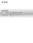
The D-Link's DGS-6600 series switch is a modular, chassis-based Ethernet backbone switch
designed for adaptability and scalability. Currently, the DGS-6600 series chassis is available in a 4slot chassis (DGS-6604) and an 8-slot chassis (DGS-6608).
Figure 1-1 DGS-6604 Product Appearance
Figure 1-2 DGS-6608 Product Appearance
DGS-6600 Configuration Guide
19
Chapter 1-DGS-6600 Series Switch Product Summary
Chapter Overview
Chassis
The DGS-6604 uses a standard 19-inch chassis, which has a height of 280mm, a width of 484mm,
and a depth of 470mm. The chassis consists of the system module layer, fan layer, and power layer.
The layer that handles system modules consists of a module plug-in frame, which is used for
connecting the various DGS-6604 modules. The built-in power shelf is located at the top of the
chassis. The fan tray is located on the right-hand side of the chassis. The fan tray consists of eight
fans. The dimension of each fan is 80x80x20mm.
The DGS-6608 chassis consists of the system module layer, fan layer, and power layer. The layer
that handles system modules consists of a module plug-in frame, which is used for connecting the
various DGS-6608 modules. The built-in power shelf is located at the top of the chassis. The fan tray
is located on the right-hand side of the chassis. The fan tray consists of sixteen fans. The dimension
of each fan is 80x80x20mm.
Module Plug-in Frame
The module plug-in frame of the DGS-6604 consists of the module slots and the backplane. The
DGS-6604 supports four module slots. The slot at the top of the Switch can only be used for the
control management module. The other three slots can be used to connect to various line cards. All
the modules supported by the DGS-6604 are of the same height, width and depth. The dimensions
of each module are a height of 42mm, a width of 388mm, and a depth of 422mm. The modules of
the DGS-6604 are inserted into the Switch horizontally. The backplane of the DGS-6604 is used to
interconnect the control management card and the line cards that have been installed in the Switch.
When the slots of the DGS-6604 are fully populated, the modules of the DGS-6604 will have the
following layout:
• One control management module.
• Three line card modules to meet the network requirements.
The slot number used for the Control Management module is 1. Slots 2, 3, and 4 are used for line
card modules.
The module plug-in frame of the DGS-6608 consists of the module slots and the backplane. The
DGS-6608 supports eight module slots. The slots 4 and 5 of the Switch can only be used for the
control management module. The other six slots can be used to connect to various line cards. All
the modules supported by the DGS-6608 are of the same height, width and depth. The dimensions
of each module are a height of 42mm, a width of 388mm, and a depth of 422mm. The modules of
the DGS-6608 are inserted into the Switch horizontally. The backplane of the DGS-6608 is used to
interconnect the control management card and the line cards that have been installed in the Switch.
When the slots of the DGS-6608 are fully populated, the modules of the DGS-6608 will have the
following layout:
• Two control management module.
• Six line card modules to meet the network requirements.
The slot number used for the Control Management module is 4 and 5. Slots 1-3 to 6-8 are used for
line card modules.
DGS-6600 Configuration Guide
20
Chapter 1-DGS-6600 Series Switch Product Summary
Module List
Module List
The DGS-6604/6608 supports the modules described below:
Model Name
Type
Description
Compatibility
DGS-6600-CM
Control Module
The Control Module is a CPU module for
the DGS-6604. The CPU module is used to
control the whole system. The DGS-6604
only supports 1 control module.
DGS-6604
DGS-6600-CM-II
Control Module
The DGS-6600-CM-II is a CPU module for
the DGS-6604/6608. The DGS-6608 is able
to support 2 control modules.
DGS-6604/DGS-6608
DGS-660024SC2XS
I/O Module
The DGS-6600-24SC2XS has 12 SFP
ports, 12 combo ports (10/100/1000Base-T/
SFP Module) and 2 SFP+ ports.
DGS-6604
DGS-6600-16XS
I/O Module
The DGS-6600-16XS has 16x 10G SFP
ports +.
DGS-6604/DGS-6608
DGS-6600-48P
I/O Module
The DGS-6600-48P has 48x 10/100/1000
RJ-45 Ports and PoE.
DGS-6604/DGS-6608
DGS-6600-48S
I/O Module
The DGS-6600-48S has 48x SFP
interfaces.
DGS-6604/DGS-6608
DGS-6600-48T
I/O Module
The DGS-6600-48T has 48x 10/100/1000
RJ-45 ports.
DGS-6604/DGS-6608
DGS-6600-48TS
I/O Module
The DGS-6600-48TS has 24x 10/100/1000
Base-T and 24x SFP ports module
interfaces.
DGS-6604/DGS-6608
DGS-6600-8XG
I/O Module
This module has 8x 10G XFP module
interfaces.
DGS-6604
Table 1-1 List of supported modules
DGS-6600-CM
Figure 1-3 DGS-6600-CM
Compact Flash Slot
The DGS-6600-CM Control Module has two compact flash slots (CF1 and CF2). Install a card in the
compact flash slot 1 to store the system configuration, log, and runtime image files. Slot 2 is for
debugging purposes (please see “Debug Information to Compact Flash” on page 601)
The LED indicator will flash green when data from the compact flash card is being accessed.
Management Port
DGS-6600 Configuration Guide
21
Chapter 1-DGS-6600 Series Switch Product Summary
Module List
The DGS-6600-CM Control Module is equipped with an auxiliary Gigabit Ethernet port for
out-of-band management. The IP address configured on the management port can be in the same
domain as the one assigned to the I/O module.
UART Console Interface
The DGS-6600-CM front panel provides two types of UART Console Interface, an RS-232
connector and a USB connector. These two interfaces are mutually exclusive, with the USB
interface having a higher priority. If the Switch is currently being managed via the RS-232 console
connection and a USB connection is established, the CLI engine will use the USB connection and
automatically disconnect the user who is connected to the Switch via the RS-232 console
connection.
The switching between the RS-232 and USB console connection is automatically controlled by the
firmware. However, this feature is disabled during system bootup. Therefore, it is strongly
recommended not to change the console connection interface during system bootup, as important
bootup information may be missed.
In order to use the USB console interface the host will need to have a terminal emulation application
(e.g., Hyper Terminal, Teraterm etc.) installed and the correct USB driver for the Switch.
NOTE: The terminal emulation application may need to be restarted if the USB
cable is disconnected and plugged it back into the host the Switch is being accessed
from.
DGS-6600-CM-II
Figure 1-4 DGS-6600-CM-II
Compact Flash Slot
The DGS-6600-CM-II Control Module has two compact flash slots (CF1 and CF2). Install a card in
the compact flash slot 1 to store the system configuration, log, and runtime image files. Slot 2 is for
debugging purposes (please see “Debug Information to Compact Flash” on page 601)
The LED indicator will flash green when data from the compact flash card is being accessed.
Management Port
The DGS-6600-CM-II Control Module is equipped with an auxiliary Gigabit Ethernet port for
out-of-band management. The IP address configured on the management port can be in the same
domain as the one assigned to the I/O module.
UART Console Interface
The DGS-6600-CM-II front panel provides two types of UART Console Interface, an RS-232
connector and a USB connector. These two interfaces are mutually exclusive, with the USB
interface having a higher priority. If the Switch is currently being managed via the RS-232 console
connection and a USB connection is established, the CLI engine will use the USB connection and
automatically disconnect the user who is connected to the Switch via the RS-232 console
connection.
DGS-6600 Configuration Guide
22
Chapter 1-DGS-6600 Series Switch Product Summary
Module List
The switching between the RS-232 and USB console connection is automatically controlled by the
firmware. However, this feature is disabled during system bootup. Therefore, it is strongly
recommended not to change the console connection interface during system bootup, as important
bootup information may be missed.
In order to use the USB console interface the host will need to have a terminal emulation application
(e.g., Hyper Terminal, Teraterm etc.) installed and the correct USB driver for the Switch.
NOTE: The terminal emulation application may need to be restarted if the USB
cable is disconnected and plugged it back into the host the Switch is being accessed
from.
DSG-6600-24SC2XS I/O Card
Figure 1-5 DGS-6600-24SC2XS
DGS-6600-48P I/O Card
Figure 1-6 DGS-6600-48P
DGS-6600-48T I/O Card
Figure 1-7 DGS-6600-48T I/O Card
DGS-6600 Configuration Guide
23
Chapter 1-DGS-6600 Series Switch Product Summary
Supported User Interfaces
DGS-6600-48S I/O Card
Figure 1-8 DGS-6600-48S I/O Card
DGS-6600-48TS I/O Card
Figure 1-9 DGS-6600-48TS I/O Card
DGS-6600-8XG I/O Card
Figure 1-10 DGS-6600-8XG I/O Card
Supported User Interfaces
The Switch can be configured using the following methods:
•
Command-Line Interface
•
MIB Browser
DGS-6600 Configuration Guide
24
Volume 1-Configuration Fundamentals / Chapter 2-Quick Start
Chapter Overview
Chapter 2
Quick Start
Chapter Overview
The following topics are included in this chapter, please go to the topic for more detailed information:
•
•
•
•
•
Chapter Overview
• An Introduction to Quickly Setting Up the DGS-6600 Series Switch
Preparation for Installation
• Static Discharge Damage Prevention
• Moving the Device
• System Grounding Requirements
• Simple Grounding Steps
Installation Site Requirements
• Ventilation Requirements
Removing and Installing Modules from the DGS-6600 Series Switch
• Removing Modules from the DGS-6600
• Installing Modules in the DGS-6604 & DGS-6608
Configuring the Connection To The Switch
• Connecting a Terminal to the Console Port
• SNMP-Based Management
An Introduction to Quickly Setting Up the DGS-6600 Series Switch
The following chapter discusses how to create user accounts on the Switch. User accounts can be
used to protect access to the command-line interface. The user can create several user accounts
with different access-levels.
Preparation for Installation
To ensure normal operation and to prolong the lifespan of the DGS-6600, the appropriate
temperature and humidity must be maintained in the equipment room (please see Table 2-1 on
page 25).
If the equipment room’s temperature and humidity do not meet the specified requirements the
equipment may sustain damage.
Operating Temperature
Operating Humidity
0ºC-50ºC
10%-90% RH non-condensed
Table 2-1
DGS-6600 Configuration Guide
25
Volume 1-Configuration Fundamentals / Chapter 2-Quick Start
Preparation for Installation
Note:
The ambient temperature and humidity should be measured at a point that is 1.5m
above the floor and 0.4m in front of the equipment when there is no protective plate
in the front or back of the equipment rack.
Static Discharge Damage Prevention
To prevent damage from static electricity, please use the following guidelines:
•
Be sure to install an adequate ground for all electronic equipment.
•
Use appropriate dust prevention measures.
•
Maintain the required humidity in the operating environment.
•
Hold circuit boards by their edges. Do not touch any components on the printed circuit
board (PCB).
•
Always wear an anti-static wrist strap when working near any electronic circuitry.
•
Do not allow clothing to touch circuit boards. An antistatic wrist strap will only prevent
static electricity from the human body, it will not reduce the static electricity build up on
clothing.
Moving the Device
The DGS-6600 series Switch is quite heavy. When handling, please use the following guidelines:
•
Avoid moving the equipment frequently.
•
Seek assistance in lifting if the weight of the chassis is more then you can lift safely alone.
•
Lift and move the chassis using the handles on the top panel (please see Table 2-1 on
page 27).
•
Turn off all power supplies and unplug all power cables before moving the equipment.
•
Completely loosen the thumb/Phillips screws and pull the card levers to remove each and
all line cards, fan tray, and power modules from the chassis before moving the chassis.
DGS-6600 Configuration Guide
26
Volume 1-Configuration Fundamentals / Chapter 2-Quick Start
Preparation for Installation
Figure 2-1
System Grounding Requirements
Proper grounding will help to ensure the stable and reliable operation of the DGS-6600 series
switch. Be sure to verify that the grounding conditions meet the grounding requirements and all
devices are grounded appropriately before using the DGS-6600 series switch.
Figure 2-2
DGS-6600 Configuration Guide
27
Volume 1-Configuration Fundamentals / Chapter 2-Quick Start
Installation Site Requirements
Simple Grounding Steps
•
Unfasten the nut on the rear grounding post of the equipment.
•
Affix the terminal of the grounding cable to the grounding pole.
•
Fasten the nut back on the grounding post.
•
Connect the other end of the grounding cable to a suitable grounding bar.
Installation Site Requirements
The DGS-6600 series switch must be used indoors. To ensure normal operation and to prolong the
lifespan of the equipment, the installation site must meet the following requirements:
Requirements for Rack Mounting:If you plan to mount the DGS-6600 in a frame, please use the following guidelines:
•
Install the switch in an open cabinet if possible. If you install the switch inside a closed
cabinet please ensure that the cabinet has a good ventilation and heat dissipation system.
•
Ensure that the cabinet is durable enough to bear the weight of the DGS-6600 and its
installed components.
•
Ensure that the dimensions of the cabinet provide enough space for the installation of the
front, rear, left and right panels of the DGS-6600 for the purpose of heat dissipation.
•
The frame should be properly grounded.
Ventilation Requirements
Table 2-3 on page 29 shows the ventilation requirements of the DGS-6600. You must allow sufficient
space near the vents to ensure proper ventilation.
After the cables have been connected, they should be arranged into bundles or placed on the
cabling rack to prevent the obstruction of air intakes and vents.
DGS-6600 Configuration Guide
28
Volume 1-Configuration Fundamentals / Chapter 2-Quick Start
Removing and Installing Modules from the DGS-6600 Series Switch
Figure 2-3
Removing and Installing Modules from the DGS-6600 Series Switch
Removing Modules from the DGS-6600
•
Unplug all copper/fibre cabling, i.e. RJ45 twisted-pair and fibre optic cables from the module to be removed.
•
Loosen and unscrew the panel’s two captive screws.
•
Use both hands to pull the levers, on the left and right hand sides of the board, to remove
the module from the DGS-6600.
Installing Modules in the DGS-6604 & DGS-6608
•
Remove the component card or blank panel as instructed in the section Removing Modules from the DGS-6600
•
Insert the new module into the guide rail of the vacant slot.
•
Use the levers on the left and right hand side to push the board into position and tighten
the two captive screws on the module using a straight screw driver.
DGS-6600 Configuration Guide
29
Volume 1-Configuration Fundamentals / Chapter 2-Quick Start
Configuring the Connection To The Switch
Configuring the Connection To The Switch
Connecting a Terminal to the Console Port
Connect the supplied RJ-45-to DB-9 adapter cable to the standard 9-pin serial port on the PC.
Connect the other end of the cable to the console port on the switch. Set the terminal emulation
software as follows:
Baud rate: 115200
Data bits: 8
Parity: None
Stop bits: 1
Flow control: None
Select VT100 for the terminal emulation mode
After you have correctly set up the terminal, plug the power cable into the power supply on the
switch. The boot sequence will appear in the terminal.
Press the Enter key at the password prompt. There is no default password for the Switch.
Enter the commands to complete your desired tasks. Many commands require administrator-level
access privileges. See the Command Line Interface (CLI) Reference Guide on the documentation
CD for a list of all commands and additional information using the CLI.
Telnet Management Users may also access the switch CLI by using the PC’s Command Prompt. To
access it from the PC, users must first ensure that a valid connection is made through the Ethernet
port of the Switch and the PC, then click Start > Programs > Accessories > Command Prompt on the
PC. Once the console window opens, enter the command telnet 10.90.90.90 (depending on
configured IP address) and press Enter on the keyboard. The user should be directed to the
opening console screen for the CLI of the switch, press the Enter key at the password prompts.
There is no default password for the Switch.
SNMP-Based Management
The Switch can be managed with D-Link D-View or any SNMP-compatible console program. The
SNMP function is disabled by default for D-Link managed switches.
DGS-6600 Configuration Guide
30
Part 1- Configuration Fundamentals
The following chapters are included in this volume:
• Command-Line Interface (CLI)
• Accessing the Command Line Interface
• User Account Configuration
• Accessing the Web Interface (Web UI)
• Time Configuration
• DGS-6600 Default Metric
Volume 1-Configuration Fundamentals / Chapter 3-Command-Line Interface (CLI)
Command-Line Interface Overview
Chapter 3
Command-Line Interface (CLI)
Command-Line Interface Overview
The following topics are included in this chapter, please go to the topic for more detailed information:
•
Command-Line Interface Overview
• An Introduction to the Command-Line Interface
• Command Mode and User Privilege Level
• User EXEC Mode Configuration Commands
• Help Features
• Editing Features
• Using Abbreviated Commands
• Error Messages
• Command Prompt
• Login Banner
• Establishing a Telnet Connection to a Remote Device
• Common Parameter Syntax Conventions
• Allowed Character Strings And String Examples
• Time and Date Configuration
An Introduction to the Command-Line Interface
The command-line interface (CLI) is a user interface that is available for inputting commands to
manage the Switch. Users can access the CLI using either the local console or a remote console.
This chapter describes the different features of the command-line interface that are available when
configuring the Switch.
Command Mode and User Privilege Level
There are several command modes available in the command-line interface (CLI). The set of
commands available, to the user, depends upon two factors, the mode the user is currently in and
their privilege level. For each case, the user can see all the commands that are available when in a
particular command mode by entering a question mark (?) at the system prompt.
The command-line interface has four privilege levels:
•
Basic User- Privilege Level 1. This user account level has the lowest priority of the user
accounts and is allowed to use, system show commands in, the terminal control interface.
The purpose of this type of user account level is for basic system checking. This user
account can only show limited information that is not related to security. The most
important limitation of this account is that there is no way of changing the access right
level.
•
Advanced User- Privilege Level 2. This user account level allowed to use the terminal
control interface to enter, some, privileged EXEC mode configurations.
DGS-6600 Configuration Guide
32
Volume 1-Configuration Fundamentals / Chapter 3-Command-Line Interface (CLI)
Command-Line Interface Overview
•
Power User- Privilege Level 12. This user account level is used to grant system
configuration rights for users who need to change or monitor system configuration, except
for security related information such as user accounts and SNMP account settings, etc.
•
Administrator- Privilege Level 15. This administrator user account level can monitor all
system information and change any of the system configuration settings expressed in this
configuration guide.
The command-line interface has three basic command modes:
•
User EXEC mode
•
Privileged EXEC mode
•
Global Configuration mode
All other sub-configuration modes can be accessed via global configuration mode.
When a user logs in to the Switch, the privilege level of the user determines the command mode the
user will enter after their initial log in. The user will either log into user EXEC mode or privileged
EXEC mode. Users with a basic user and advanced user level will log into the Switch in user EXEC
mode. Users with power user and administrator level accounts will log into the Switch in privileged
EXEC mode. Therefore, user EXEC mode can operate at either basic user level or advanced user
level, and privileged EXEC mode can operate at either power user level or administrator level. The
user can only enter global configuration mode from privileged EXEC mode. Therefore, global
configuration mode can be accessed by users who have power user or administrator level user
accounts. As for sub-configuration modes, a subset of those can only be accessed by users who
have the highest secure administrator level privileges.
In user EXEC mode at advanced user level, the user is allowed to enter privileged EXEC mode by
entering the enable password. In privileged EXEC mode, the user is allowed to exit to the user
EXEC mode at advanced user level by entering the disable command. The enable password and
disable commands are functions that can be used to switch between user EXEC mode and
privileged EXEC mode.
DGS-6600 Configuration Guide
33
Volume 1-Configuration Fundamentals / Chapter 3-Command-Line Interface (CLI)
Command-Line Interface Overview
Figure 3-1 Command Mode State Diagram
NOTE: Not all configuration modes are listed in the above figure. For example, in global
configuration mode, enter “router ospf” to enter OSPF router configuration mode
Table 2-1 describes in brief the available command modes. Only the basic command modes and
some of the sub-configuration modes are enumerated. The basic command modes and basic
sub-configuration modes are further described in the following chapters. Descriptions for the rest of
the sub-configuration modes are not provided in this section. For more information on the additional
sub-configuration modes, the user should refer to the chapters relating to these functions.
DGS-6600 Configuration Guide
34
Volume 1-Configuration Fundamentals / Chapter 3-Command-Line Interface (CLI)
User EXEC Mode Configuration Commands
The available command modes and privilege levels are described below:
Command Mode & Privilege Level
Purpose
User EXEC mode at Basic User level
For checking basic system settings, allowing users to change
the local terminal session settings, and verifying basic network
connectivity. Checking security related settings is not allowed
at this command mode and privilege level.
User EXEC mode at Advanced User level
This level has almost the same access rights as user EXEC
mode at basic user level, except that a user in this mode and
at this level can enter privileged EXEC mode by entering the
enable command.
Privileged EXEC mode at Power User level
For changing both local and global terminal settings,
monitoring, and performing certain system administration
tasks. The system administration tasks that can be performed
at this level includes the clearing of system configuration
settings, except for any security related information, such as
user accounts, SNMP account settings etc.
Privileged EXEC mode at Administrator level
This level is identical to privileged EXEC mode at power user
level, except that a user at the administrator level can monitor
and clear security related settings.
Global Configuration Mode at Power User level
For applying global settings, except for security related
settings, on the entire Switch. In addition to applying global
settings on the entire Switch, the user can access other
sub-configuration modes from global configuration mode.
Global Configuration Mode at Administrator
level
For applying global settings on the entire Switch. In addition to
applying global settings on the entire Switch, the user can
access other sub-configuration modes from global
configuration mode.
Interface Configuration Mode at Power User
level
For applying interface related settings.
VLAN Interface Configuration Mode
For applying VLAN interface related settings.
VLAN Configuration Mode
For applying settings to a VLAN.
IP Access-List Configuration Mode
For specifying filtering criteria for an IP access list.
Table 3-1 Command Modes and Privilege Levels
User EXEC Mode Configuration Commands
User EXEC Mode at Basic User Level
This command mode is mainly designed for checking basic system settings, allowing users to
change the local terminal session settings and carry out basic network connectivity verification. One
limitation of this command mode is that it cannot be used to display information related to security.
The most significant limitation of this command mode is that there is no way of changing the access
right level of the logged in user.
This command mode can be entered by logging in as a basic user.
User EXEC Mode at Advanced User Level
User EXEC mode at advanced user level has the same purpose as user EXEC mode at basic user
level, except that user EXEC mode at advanced user level is allowed to use the enable command to
enter privileged EXEC mode.
DGS-6600 Configuration Guide
35
Volume 1-Configuration Fundamentals / Chapter 3-Command-Line Interface (CLI)
User EXEC Mode Configuration Commands
This command mode can be entered by logging in as an advanced user or by using the disable
command in privileged EXEC mode.
In the following example, the user is currently logged in as an advanced user in privileged EXEC
mode and uses the disable command to return to user EXEC mode at advanced user level:
DGS-6600:15#disable
DGS-6600:2>
Privileged EXEC Mode at Power User Level
Users logged into the Switch in privileged EXEC mode at this level can change both local and global
terminal settings, monitor, and perform system administration tasks like clearing configuration
settings (except for security related information such as user accounts, SNMP account settings etc.)
There are two methods that a user can use to enter privileged EXEC mode at power user level. The
first method is to login to the Switch with a user account that has a privilege level of 12. The other
method is to use the enable privilege LEVEL command in user EXEC mode.
In the following example, the user enters privileged EXEC mode at power user level by logging in
with a user account called “power-user” that has a privilege level of 12:
User Access Verification
Username: power-user
Password:
DGS-6600 Chassis-based High-Speed Switch
Command Line Interface
Firmware: 2.10.011
Copyright (c) 2012 D-Link Corporation. All rights reserved.
DGS-6600:12#
In the following example, the user enters the enable privilege LEVEL command in user EXEC
mode to enter privileged EXEC mode at Power User level:
DGS-6600:2>enable privilege 12
DGS-6600:12#
Privileged EXEC Mode at Administrator Level
This command mode has a privilege level of 15. Users logged in with this command mode can
monitor all system information and change any system configuration settings mentioned in this
Configuration Guide.
There are two methods that a user can use to enter privileged EXEC mode at administrator level.
The first method is to login to the Switch with a user account that has a privilege level of 15. The
second method requires a user to login to the Switch in as a user with an advanced user or power
user level and use the enable privilege LEVEL command.
In this command mode, the user can return to user EXEC mode at an advanced user level by
entering the disable command.
DGS-6600 Configuration Guide
36
Volume 1-Configuration Fundamentals / Chapter 3-Command-Line Interface (CLI)
User EXEC Mode Configuration Commands
In the following example, the user is currently logged in as an administrator in privileged EXEC
mode and uses the disable command to return to user EXEC mode at an advanced user level:
DGS-6600:15#disable
DGS-6600:2>
In the following example, the user enters the enable privilege LEVEL command in privileged EXEC
mode at power user level to enter privileged EXEC mode at an administrator level:
DGS-6600:12#enable privilege 15
DGS-6600:15#
Global Configuration Mode
The primary purpose of global configuration mode is to apply global settings on the entire Switch.
Global configuration mode can be accessed at both power user and administrator level. However,
security related settings are not accessible at power user level. In addition to applying global
settings on the entire Switch, the user can also access other sub-configuration modes.
In order to access global configuration mode, the user must be logged in as an administrator or
power user and use the configure terminal command in privileged EXEC mode.
In the following example, the user is logged in as an Administrator in privileged EXEC mode and
uses the configure terminal command to access global configuration mode:
DGS-6600:15#configure terminal
DGS-6600:15(config)#
The exit command is used to exit global configuration mode and return to privileged EXEC mode.
The procedures to enter the different sub-configuration modes can be found in the related chapters
in this Configuration Guide. The command modes are used to configure the individual functions.
Interface Configuration Mode
Interface configuration mode is used to configure the parameters for an interface or a range of
interfaces. An interface can be a physical port, VLAN, or other virtual interface. Thus, interface
configuration mode is distinguished further according to the type of interface. The command prompt
for each type of interface is slightly different.
VLAN Interface Configuration Mode
VLAN interface configuration mode is one of the available interface modes and is used to configure
the parameters of a VLAN interface.
To access VLAN interface configuration mode, use the following command in global configuration
mode:
Command
Explanation
DGS-6600:15(config)#interface vlanVLAN-ID
Enters VLAN interface configuration mode.
DGS-6600 Configuration Guide
37
Volume 1-Configuration Fundamentals / Chapter 3-Command-Line Interface (CLI)
User EXEC Mode Configuration Commands
Using the End and Exit Commands
The end command can be used to return to privileged EXEC mode from any configuration task in
any configuration mode. If a user enters the end command while in user EXEC mode, the user will
be logged out of the session. The exit command is used to end the current mode and return to the
mode that the user was in previously. If the Switch is in global configuration mode, the exit
command will return the Switch to privileged EXEC mode.
Use the following commands to end the current configuration session or exit the current mode:
Command
Explanation
end
Ends the current configuration session.
exit
Exits the current mode.
In the following example, the user uses the end command in interface mode to return to privileged
EXEC mode:
DGS-6600:15(config-if)#end
DGS-6600:15#
In the following example, the exit command is used in interface mode to return to global
configuration mode:
DGS-6600:15(config-if)#exit
DGS-6600:15(config)#
Help Features
The help feature allows the user to get instant and interactive guidance information on using the CLI
commands. The following list describes the different help features that are available on the Switch:
Command
Purpose
ABBREVIATED-COMMAND-ENTRY?
Obtains a list of commands that begin with a particular character
string. For example:
DGS-6600:15#di?
dir
List directory contents
disable Turn off privileged mode command
DGS-6600:15#
ABBREVIATED-COMMAND-ENTRY <TAB>
Completes a partial command name.
For example:
DGS-6600:15#show spa<TAB>
DGS-6600:15#show spanning-tree
Table 3-2 Help System
DGS-6600 Configuration Guide
38
Volume 1-Configuration Fundamentals / Chapter 3-Command-Line Interface (CLI)
User EXEC Mode Configuration Commands
Command
Purpose
?
Lists all the commands that are available in a particular command
mode. For example:
DGS-6600:2>?
Exec commands:
clear
copy
crypto
dir
disable
enable
end
COMMAND ?
Reset function
Copy
Generate encrypt key
List of directory contents
Turn off privileged mode command
Turn on privileged mode command
Exit from the EXEC
Lists the associated keywords for a command. For example:
DGS-6600:15#copy ?
WORD
Specifies the URL
debug
Debug information
running-config The running-config
startup-config The startup-config
system-log
System-log file
DGS-6600:15#
COMMAND KEYWORD ?
Lists the associated arguments for a keyword. For example:
DGS-6600:15(config)#spanning-tree mode ?
mstp Multiple Spanning Tree Protocol
rstp Rapid Spanning Tree Protocol
stp
Spanning Tree Protocol(Compatible Mode)
DGS-6600:15(config)#
Table 3-2 Help System (continued)
DGS-6600 Configuration Guide
39
Volume 1-Configuration Fundamentals / Chapter 3-Command-Line Interface (CLI)
User EXEC Mode Configuration Commands
The following example, the user enters the abbreviated command entry conf and the <TAB> key to
automatically complete the configure command:
DGS-6600:15#conf<TAB>
Help Command
A user can enter the help command in any command mode to display a brief description of the help
system.
In the following example, the user has entered the help command in user EXEC mode:
DGS-6600:2>help
CLI provides advanced help feature. When you need help,
anytime at the command line please press ‘?’.
If nothing matches, the help list will be empty and you must backup
until entering a ‘?’ shows the available options.
Two styles of help are provided:
1. Full help is available when you are ready to enter a
command argument (e.g. ‘show ?’) and describes each possible
argument.
2. Partial help is provided when an abbreviated argument is entered
and you want to know what arguments match the input
(e.g. ‘show ve?’.)
DGS-6600:2>
Editing Features
The CLI user interface supports the following keystrokes for editing purposes:
Keystroke
Purpose
<DELETE>
Deletes character under the cursor and shifts remainder of the line to the left.
<BACKSPACE>
Deletes character to the left of the cursor and shifts remainder of the line to the
left.
<LEFT ARROW>
Moves cursor to the left.
<RIGHT ARROW>
Moves cursor to the right.
<CTRL+R>
Redisplays the current command line if the Switch suddenly sends messages to
the screen.
<RETURN>
Scrolls down to display the next line.
<SPACE>
Scrolls down to display the next page.
<ESC>
Escapes from the page being displayed.
<TAB>
Automatically completes a command.
Table 3-3 Editing Features
DGS-6600 Configuration Guide
40
Volume 1-Configuration Fundamentals / Chapter 3-Command-Line Interface (CLI)
User EXEC Mode Configuration Commands
Using Abbreviated Commands
The Switch supports abbreviated commands. In order to enter a command, a user only needs to
input enough characters for the Switch to uniquely recognize a command. For example if the user
types show span, the Switch will identify the command as show spanning-tree. However, if the
user does not type enough characters to uniquely identify the command an ambiguous command
error message will display. For example if the user types log the Switch cannot identify if the
command is login or logout.
To automatically complete a command with a short prefix, the user needs to press the <TAB> key
on their keyboard.
For example:
If the user types show span and presses the <TAB> key on their keyboard the command will
automatically complete to display show spanning-tree.
The No and Default Command Forms
Many of the configuration commands can be disabled or reset to their default values by using a no
prefix before the command. One function that supports the no command form is the password
encryption command. For example, to disable the password encryption function globally on the
Switch the user would need to enter the no password encryption command in global configuration
mode. In order to re-enable the password encryption function, the user would need to enter the
password encryption command in global configuration mode.
Example of Using the No Command Form
In the following example, the user has typed in the no password encryption command in global
configuration mode.
DGS-6600:15(config)#no password encryption
DGS-6600:15(config)#
Some commands also have a default option, which the user can use to return the parameters of a
command back to factory defaults. One command that supports the default option is the ip telnet
service-port command. For example, entering the default ip telnet service-port command in
global configuration mode will return the banner login message back to factory defaults.
Example of Using the Default Command Form
In the following example, the default ip telnet service-port command is entered in global
configuration mode to return the Telnet service port to default settings.
DGS-6600:15(config)#default ip telnet service-port
DGS-6600:15(config)#
DGS-6600 Configuration Guide
41
Volume 1-Configuration Fundamentals / Chapter 3-Command-Line Interface (CLI)
User EXEC Mode Configuration Commands
Error Messages
The following table explains the error messages that will appear if the user inputs a command
incorrectly in the CLI:
Error Message
Meaning
Ambiguous command
Not enough keywords were entered for the Switch to
recognize the command.
Incomplete command
The command was not entered with all the required keywords.
Invalid input detected at ^ marker
The command was entered incorrectly.
Argument is too long
The length of the command is longer than 384 characters.
Users can only input an argument that is less than, or equal to
384 characters.
Table 3-4 Error Messages
Example of an Ambiguous Command Error
In the following example, the user has typed in the word log in privileged EXEC mode. However,
there are not enough letters to enable the Switch to identify if the command is login or logout.
DGS-6600:15#log
% Ambiguous command:
DGS-6600:15#
“log”
Example of an Incomplete Command Error
In the following example, the user has typed in the ping command in privileged EXEC mode.
However, there are not enough keywords for the Switch to execute the command.
DGS-6600:15#ping
% Incomplete command.
DGS-6600:15#
Example of an Invalid Input Detected at ^ Marker Error
In the following example, the user has tried to enter the shutdown command in global configuration
mode. Since the shutdown command is not available in global configuration mode, the “Invalid
input detected at marker” error appears in the console window, indicating the location of the error.
DGS-6600:15(config)#shutdown
^
% Invalid input detected at ‘^’ marker.
DGS-6600:15(config)#
DGS-6600 Configuration Guide
42
Volume 1-Configuration Fundamentals / Chapter 3-Command-Line Interface (CLI)
User EXEC Mode Configuration Commands
Using Command History
The Switch CLI provides a history or record of commands that have been entered in the current
console session. This feature is particularly useful for recalling long or complex commands or
entries, including access lists. The Switch records 20 command lines in its history buffer. The
command history feature is enabled by default.
The commands in the history buffer can be displayed by using the show history command.
The following example uses the show history command to display the commands in the history
buffer:
DGS-6600:15#show history
1 enable
2 configure terminal
3 default ip telnet service-port
4 end
5 show history
DGS-6600:15#
Recalling Commands
To recall commands from the history buffer, use one of the following key combinations:I
Command
Explanation
<CTRL-P> or the <UP ARROW> key.
Recalls commands in the history buffer, beginning with the most
recent command. Repeat the key sequence to recall successively
older commands.
<CTRL-N> or the <DOWN ARROW> key.
Returns to more recent commands in the history buffer after
recalling commands with the <CTRL-P> or the <UP ARROW>
key. Repeat the key sequence to recall the most recent
commands successively.
Table 3-5 Recalling Commands
Command Prompt
The user can change the command prompt of the Switch so that it displays the product name,
system name, or a user-defined string. The user can also specify if the command prompt displays
the level of the user that is currently logged into the Switch. By default the CLI Prompt displays the
product name and the user level.
A command prompt is shown in the following format: WWWW:XX(YY)Z
Letter
Description
WWWW
Represents the model name of the Switch, e.g. DGS-6600, the system name of the
Switch, or the user-defined string. This part of the command prompt is always
followed by a colon.
XX
Represents the user access level, e.g. 1 indicates a Basic User, 2 indicates an
Advanced User, 12 indicates a Power User, and 15 indicates an Administrator.
Table 3-6 Command Prompts
DGS-6600 Configuration Guide
43
Volume 1-Configuration Fundamentals / Chapter 3-Command-Line Interface (CLI)
User EXEC Mode Configuration Commands
Letter
Description
(YY)
Represents the configuration mode that the user is in. The available modes are
Global Configuration mode, Interface Configuration mode, VLAN Configuration mode,
Router mode, etc.
Z
Represents if the user is in user EXEC mode or privileged EXEC mode. The “>”
symbol indicates that the user is in user EXEC mode. The “#” symbol indicates that
the user is in privileged EXEC mode or a configuration mode.
Table 3-6 Command Prompts (continued)
The following table lists some examples of the command prompts that the user will see in different
command modes. In the following table the Switch has been configured to use the product name as
the command prompt and display the privilege level of the user:
Command Mode and Privilege Level
Command Prompt
User EXEC mode at Basic User level
DGS-6600:1>
User EXEC mode at Advanced User level
DGS-6600:2>
Privileged EXEC mode at Power User level
DGS-6600:12#
Privileged EXEC mode at Administrator level
DGS-6600:15#
Global Configuration mode
DGS-6600:15(config)#
Interface Configuration mode
DGS-6600:15(config-if)#
VLAN Interface Configuration mode
DGS-6600:15(config-if)#
Table 3-7 Command Prompts
If the user wants to change the CLI prompt to be the product name, system name, or a user-defined
string, and specify if the privilege level should be displayed or hidden, the following command
should be entered in global configuration mode:
Command
Explanation
command prompt [level | no-level] [string
STRING | product-name | system-name]
Configures the CLI prompt.
In the following example, the user configures the command prompt to display the privilege level and
use the user-defined string ”Comms-Rm”:
DGS-6600:2>enable
DGS-6600:15#configure terminal
DGS-6600:15(config)#command prompt level string Comms-Rm
Comms-Rm:15(config)#end
Filtering the Output from the Show Command
The user can filter the output of the show command to match a given expression as well as any of
lines that are associated with the expression.
DGS-6600 Configuration Guide
44
Volume 1-Configuration Fundamentals / Chapter 3-Command-Line Interface (CLI)
User EXEC Mode Configuration Commands
show COMMAND | {begin | include | exclude} REGULAR-EXPRESSION
Syntax
Description
COMMAND
Represents any show command.
|
The vertical bar (pipe symbol) indicates that an output processing specification
will follow.
begin
Specifying the begin syntax causes the Switch to search the output from the first
instance of a specified string.
include
Specifying the include syntax causes the Switch to filter the output so that only
lines with a particular regular expression are displayed.
exclude
Specifying the exclude syntax causes the Switch to exclude any lines that
contain a particular regular expression.
REGULAR-EXPRESSION
Represents any regular expression (text string) that is found in the output of the
show command.
In the following example, the user filters the output of the show logging-buffer command so that
only the entries for the first instances of eth4.43:
DGS-6600:2>enable
DGS-6600:15#show logging buffer | begin eth4.43
...skipping
7
2010-08-26 07:38:28
eth4.43 state change from FWD to BLK for MSTID 0
6
2010-08-26 07:38:27
Interface eth4.43 is down
5
2010-08-26 07:38:27
Interface vlan1 is down
4
2010-08-26 07:38:09
eth4.43 state change from LRN to FWD for MSTID 0
3
2010-08-26 07:38:09
eth4.43 state change from BLK to LRN for MSTID 0
2
2010-08-26 07:38:06
Interface eth4.43 is up
1
2010-08-26 07:38:06
Interface vlan1 is up
DGS-6600:15#
In the following example, the user filters the output of the show logging-buffer command so that
only lines containing the expression eth4.43 are displayed:
DGS-6600:2>enable
DGS-6600:15#show logging buffer | include eth4.43
7
2010-08-26 07:38:28 eth4.43 state change from FWD to BLK for MSTID 0
6
2010-08-26 07:38:27 Interface eth4.43 is down
4
2010-08-26 07:38:09 eth4.43 state change from LRN to FWD for MSTID 0
3
2010-08-26 07:38:09 eth4.43 state change from BLK to LRN for MSTID 0
2
2010-08-26 07:38:06 Interface eth4.43 is up
DGS-6600:15#
DGS-6600 Configuration Guide
45
Volume 1-Configuration Fundamentals / Chapter 3-Command-Line Interface (CLI)
User EXEC Mode Configuration Commands
In the following example, the user filters the output of the show logging-buffer command so that
lines containing the expression eth4.43 are filtered out:
DGS-6600:2>enable
DGS-6600:15#show logging buffer | exclude eth4.43
Total logs:9
Index Date
Times
Log Text
----------------------------------------------------------------------------9
2010-08-26 07:42:28 The running CFG was saved to the startup CFG by user
anonymous, IP 0.0.0.0, via console
8
2010-08-26 07:38:49 Successfully login to the system by user anonymous, I
P 10.73.87.1, via Telnet at privilege level 2
5
2010-08-26 07:38:27
Interface vlan1 is down
1
2010-08-26 07:38:06
Interface vlan1 is up
DGS-6600:15#
Login Banner
The user can create a login banner that will display after successfully logging into the Switch. This
feature is useful as it can be used as a method for informing users about any future events or useful
information that the administrator would like to announce to any users who are connected to the
Switch, such as an upgrade on the network.
By default, the login banner displays information about the Switch model and firmware version.
To configure a login banner, enter the following command in global configuration mode:
Command
Explanation
banner login STRING
Configure the login banner.
In the following example, the user configures a login banner that displays the following message:
“Essential Network Maintenance at 18:00 tonight!
Make sure you are logged off the network before 18:00.
For more information contact the System Administrator on extension: 6716.”
DGS-6600 Configuration Guide
46
Volume 1-Configuration Fundamentals / Chapter 3-Command-Line Interface (CLI)
User EXEC Mode Configuration Commands
DGS-6600:15#configure terminal
DGS-6600:15(config)#banner login Essential Network Maintenance at 18:00 tonight!/
nMake sure you are logged off the network before 18:00./nFor more information
contact the System Administrator on extension: 6716.
DGS-6600:15(config)#
The following example displays the login banner that will appear after logging into the Switch:
User Access Verification
Username: adv-user
Password:
Essential Network Maintenance at 18:00 tonight!
Make sure you are logged off the network before 18:00.
For more information contact the System Administrator on extension: 6716.
DGS-6600:2>
The following example uses the default command in global configuration mode to return the login
banner back to default settings:
DGS-6600:15(config)#default banner login
DGS-6600:15(config)#
Establishing a Telnet Connection to a Remote Device
The user can establish a connection to a remote device that supports the Telnet protocol:
Command
Explanation
telnet {IP-ADDRESS | IPV6-ADDRESS}[TCPPORT]
Establishes a connection to a remote device that
supports the Telnet protocol.
In the following example, the user establishes a Telnet connection to a device that has an IP
address of 10.1.1.254:
DGS-6600:2>telnet 10.1.1.254
Connecting to 10.1.1.254 ...
Connected to 10.1.1.254.
Escape character is ‘Ctrl-_’.
Telnet connecting ...
User Access Verification
Username:
DGS-6600 Configuration Guide
47
Volume 1-Configuration Fundamentals / Chapter 3-Command-Line Interface (CLI)
User EXEC Mode Configuration Commands
In the following example, the user establishes a Telnet connection to a device that has an IPv6
address of 2001:e10:5c00:2::101:253, with the default port 23:
DGS-6600:2>telnet 2001:e10:5c00:2::101:2534
Connecting to 2001:e10:5c00:2::101:253 ...
Connected to 10.1.1.254.
Escape character is ’Ctrl-_’.
Telnet connecting ...
User Access Verification
Username:
Ethernet
Workstation
Telnet Client
Telnet Server
Figure 2-2 Workstation to Telnet Server diagram.
Common Parameter Syntax Conventions
The following section describes the syntaxes used for commonly used command parameters.
Interface-ID
An interface can be a physical port, a VLAN, or a channel-group. For a physical port in an Ethernet
switch, an interface-ID appears in the following format:
ethx.y
•
x—For a standalone switch, this number is always 1. This can also represent the unit
number (stackable system) or slot number (chassis system).
•
y—The interface number on the switch. The port numbers always begin at 1, starting on
the left, when facing the front of the Switch, for example, eth1.1, eth1.2.
For a VLAN interface, the format is vlanVLAN-ID. e.g. vlan1.
For a channel group (link aggregated) interface, the format is port-channelGROUP-NUM, for
example: port-channel3
MAC Address
The acceptable formats for a MAC Address are 00-01-80-40-30-20, 00:01:80:40:30:20,
000180403020, and 0001.8040.3020.
The MAC address will always be displayed in the following format: 00-01-80-40-30-20
DGS-6600 Configuration Guide
48
Volume 1-Configuration Fundamentals / Chapter 3-Command-Line Interface (CLI)
User EXEC Mode Configuration Commands
IP Parameters
An IP address will always be in the format of A.B.C.D. The subnet mask can be represented in
mask bit form or as an integer indicating the number of mask bits, as shown below:
A.B.C.D xxx.xxx.xxx.xxx
A.B.C.D/N
For example – 10.9.18.2 255.0.0.0 is interchangeable with 10.9.18.2/8. Note that a space is
required between A.B.C.D and xxx.xxx.xxx.xxx. A back slash ‘/’ has to be inserted between
A.B.C.D and N.
Allowed Character Strings And String Examples
Allowed Characters for File Name
A-Z
a-z
0-9
!#$%&'( )+,-.=@[ ]^_` { } ~
space
Allowed Characters for General Strings that Allow Spaces
A-Z
a-z
0-9
!#$%&'( )+,-.=@[ ] ^_` { } ~ / \ : * <
space
Allowed Characters for General Strings that Do Not Allow Spaces
A-Z
a-z
0-9
!#$%&'( )+,-.=@[ ]^_`{ } ~ / \ : * <
Encrypted Password
An encrypted password should start with *@&.
The allowed characters for an encrypted password are:
A-Z
a-z
0-9
+/
DGS-6600 Configuration Guide
49
Volume 1-Configuration Fundamentals / Chapter 3-Command-Line Interface (CLI)
User EXEC Mode Configuration Commands
Time and Date Configuration
The following section defines the display format the Switch uses to represent durations, calendar
date, and time respectively.
Durations
Durations are used to define the amount of intervening time in a time interval.
The Switch uses the following format to represent time, [v]DT[v]H[v]M[v]S. In this representation, the
value for each of the date and time elements replaces the date and time elements that follow the [v].
Leading zeros for each of the date and time elements are not required. Each date and time element
use a capital letter as a designator that is not replaced.
The following table explains the designators used for each date and time element:
Designator
Description
D
Used as the Day designator. This designator follows the
value for the number of days.
T
Used as the Time designator. This designator precedes
the time components.
H
Used as the Hour designator. This designator follows the
value for the number of hours.
M
Used as the Minute designator. This designator follows the
value for the number of minutes.
S
Used as the Second designator. This designator follows
the value for the number of seconds.
Table 3-8 Date and Time Element Designators
For example, a duration lasting "six days, seven hours, fifteen minutes, and nine seconds would be
represented as as follows, "6DT7H15M9S". If the value of a date and time element, including their
designator, is zero, the value may be omitted. Lower values can also be omitted for reduced
precision. For example, the following format, "13DT21H" is an acceptable form to represent 13 days
and 21 hours.
Calendar Dates
The Switch uses the following format to represent calendar dates, YYYY-MM-DD.
The following table explains the components that the Switch uses to represent calendar dates:
Date Component
YYYY
MM
Description
Used to indicate a four-digit year, 0000 through to 9999.
Used to indicate a two-digit month of the year, 01
through to 12.
Table 3-9
DGS-6600 Configuration Guide
50
Volume 1-Configuration Fundamentals / Chapter 3-Command-Line Interface (CLI)
Date Component
DD
User EXEC Mode Configuration Commands
Description
Used to indicate a two-digit day of that month, 01
through to 31.
Table 3-9
For example, the Switch would represent the date “22nd of February 2012" as "2012-02-22."
This Switch allows calendar dates to be written with reduced precision. For example, if the user
inputs "2012-02" the Switch will identify the calendar date as "2012 February". If the user inputs
"2012" the Switch will identify the year as “2012”.
The format of YYYY-MM-DD is necessary for complete calendar date representations.
Time
The Switch uses the 24-hour clock system, with the following format: [hh]:[mm]:[ss].
The following table explains the components that the Switch uses to represent the time:
Date Component
Description
[hh]
Used to refer to a zero-padded hour between 00 and 24,
where 24 is only used to notate midnight at the end of a
calendar day.
[mm]
Used to refer to a minute between 00 and 59
[ss]
Used to refer to a second between 00 and 59.
Table 3-10 Switch Time Components
For example "14:50:30".
Midnight is a special case and can be referred to as either "00:00" or "24:00". The notation "00:00" is
used at the beginning of a calendar day and is used more frequently. The notation usually used at
the end of a day is "24:00".
Countdown Timer
The Switch uses most its timers for protocol synchronization. The Switch timers usually use seconds
or milliseconds time units. The Switch usually abbreviates seconds to sec and milliseconds to msec
for unified display formatting.
DGS-6600 Configuration Guide
51
Volume 1-Configuration Fundamentals / Chapter 4-Accessing the Command Line Interface
Chapter Overview
Chapter 4
Accessing the Command Line Interface
Chapter Overview
The following topics are included in this chapter, please go to the topic for more detailed information:
•
Chapter Overview
• An Introduction to Accessing the Switch Using a Console Connection
• Accessing the Switch Using a Telnet Connection
• Enabling the Telnet Service
• Configuring the Telnet Service Port
• Specifying Telnet Terminals
• Displaying Trusted Host Telnet Terminals
• Closing an Active Terminal Session
• Terminal Settings
• Configuring the Number of Lines Displayed on Terminal Screen
• Configuring the Max Number of Characters Displayed per Terminal Line
• Configuring the Terminal Timeout
• List of Constants and Default Settings
An Introduction to Accessing the Switch Using a Console Connection
Initial configuration of the Switch needs to be carried out using one of the UART console interfaces
available on the DGS-6600-CM front panel. The DGS-6600-CM front panel provides two types of
UART console interface, an RS-232 connector and a USB connector.
In order to use the RS-232 or USB console interface the host will need to have a terminal emulation
application (e.g., Hyper Terminal, Teraterm etc.) installed. If using the USB console interface, the
correct USB driver for the Switch will also need to be installed on the connected host.
If using the RS-232 console connection, the host will need to have the following equipment:
•
A terminal or a computer with an RS-232 serial port and the ability to emulate a terminal.
•
A null modem or straight-through RS-232 cable with a female DB-9 connector for the console port on the Switch.
Carry out the following to connect a terminal to the RS-232 console port:
1) Connect the female connector of the RS-232 cable directly to the console port on the Switch,
and tighten the captive retaining screws.
2) Connect the other end of the cable to a terminal or to the serial connector of a computer
running terminal emulation software. Set the terminal emulation software as follows:
3) Select the appropriate serial port (COM port 1, COM port 2, etc).
4) Set the baud rate to 115200 bps.
5) Set the data format to 8 data bits, 1 stop bit, and no parity.
DGS-6600 Configuration Guide
52
Volume 1-Configuration Fundamentals / Chapter 4-Accessing the Command Line Interface
Chapter Overview
6) Set flow control to hardware.
7) Under Properties, select VT100 for Emulation mode.
8) After correctly setting up the terminal, plug the power cable into the power receptacle on the
back of the Switch. The boot sequence appears in the terminal.
9) After the boot sequence completes, the console login screen displays.
10) Ensure that any terminal or PC being used to make a console connection is configured to
match these settings.
11) If using the USB console connection, the host will need to have the following equipment:
•
A terminal or a computer with USB port and the ability to emulate a terminal.
•
A Type A to Type B USB cable.
Carry out the following to connect a terminal to the USB console port:
1) Connect the Type A connector end of the USB cable to an available USB port on the Switch.
2) Connect the Type B connector end of the USB cable to an available USB port on the computer
running the terminal emulation software. Set the terminal emulation software using the same
procedure described above.
NOTE: If both the RS-232 and USB connection are active on the device, the USB connection will have priority over the RS-232 connection. If the device is currently being managed
via the RS-232 console connection and a USB connection is established, the system will
disconnect the RS-232 connection and switch over to the USB connection.
If connecting to the Switch for the first time, press the <RETURN> key to start the login process.
In the following example, the user has started a console connection and enters privileged EXEC
mode:
DGS-6600 Chassis-based High-Speed Switch
Command Line Interface
Firmware: 3.00.080
Copyright (c) 2012 D-Link Corporation. All rights reserved.
DGS-6600:2>enable
DGS-6600:15#
DGS-6600 Configuration Guide
53
Volume 1-Configuration Fundamentals / Chapter 4-Accessing the Command Line Interface
Accessing the Switch Using a Telnet Connection
If the user has created a user name and password, the Switch will prompt the user to enter a user
name and password before accessing a command mode. The command mode the user initially
enters will depend on the privilege level assigned to the user name.
In the following example the user is prompted to enter a user name and password. The user enters
a user name with administrator level privileges and directly enters privileged EXEC mode:
User Access Verification
Username:Admin-User
Password:
DGS-6600 Chassis-based High-Speed Switch
Command Line Interface
Firmware: 3.00.080
Copyright (c) 2012 D-Link Corporation. All rights reserved.
DGS-6600:2>enable
DGS-6600:15#
NOTE: The user has three attempts to enter the correct password, before the login attempt
is refused.
Accessing the Switch Using a Telnet Connection
The Switch can be managed using a Telnet connection. Up to eight simultaneous Telnet sessions
can be made from the Switch.
NOTE: In order to successfully connect to the Switch using Telnet, an IP address needs to
be configured on the Switch
To start a Telnet connection on the Switch open a terminal emulation application on the PC and
enter the Telnet command followed by the IP address of the Switch.
In the following example, a Telnet connection is established to a Switch with an IP address of
10.73.87.99:
C:\>telnet 10.73.87.99
Telnet connecting ...
DDGS-6600 Chassis-based High-Speed Switch
Command Line Interface
Firmware: 3.00.080
Copyright (c) 2012 D-Link Corporation. All rights reserved.
DGS-6600:2>enable
DGS-6600:15#
DGS-6600 Configuration Guide
54
Volume 1-Configuration Fundamentals / Chapter 4-Accessing the Command Line Interface
Accessing the Switch Using a Telnet Connection
Enabling the Telnet Service
To re-enable the Telnet service after it has been disabled by the user, enter the following commands
in privileged EXEC mode:
Command
Explanation
configure terminal
Enters global configuration mode.
ip telnet server
Enables the Telnet service.
Configuring the Telnet Service Port
The user can change the port used by the Telnet service by using the following command in global
configuration mode:
Command
Explanation
ip telnet service-port TCP-PORT
Configures the port used by the Telnet service.
To return the Telnet service on the Switch to the default setting use the default form of the
command.
In the following example, the user configures the TCP port number for Telnet to be 3000:
DGS-6600:15#configure terminal
DGS-6600:15(config)#ip telnet service-port 3000
DGS-6600:15(config)#end
Specifying Telnet Terminals
The user can specify the hosts that are allowed to manage the Switch using a Telnet connection by
using the following command in global configuration mode:
Command
Explanation
ip trusted-host {IP-ADDRESS | NETWORKADDRESS/PREFIX-LENGTH} telnet
Specifies a host that is allowed to manage the
Switch using a Telnet connection.
In the following example, a trusted host with IP address 10.73.87.3 is allowed to manage the switch
using a Telnet connection:
DGS-6600:15#configure terminal
DGS-6600:15(config)#ip trusted-host 10.73.87.3 telnet
DGS-6600:15(config)#end
DGS-6600 Configuration Guide
55
Volume 1-Configuration Fundamentals / Chapter 4-Accessing the Command Line Interface
Terminal Settings
Displaying Trusted Host Telnet Terminals
The user can display a list of the hosts that are allowed to manage the Switch using a Telnet
connection by entering the following command in privileged EXEC mode:
Command
Explanation
show ip trusted-host telnet
Displays a list of the hosts that are allowed to
manage the Switch using a Telnet connection.
In the following example, the user displays a list of the hosts that are allowed to managed the Switch
using a Telnet connection:
DGS-6600:15#show ip trusted-host telnet
Index IP/Network Address
Valid to Access
=====================================================
01
10.78.62.1/32
TELNET
02
10.73.87.1/32
TELNET
Total Entries: 2
DGS-6600:15#
Closing an Active Terminal Session
An active session can be ended using either the logout, exit, or end commands.
Command
Explanation
logout
Ends an active session.
exit
If the exit command is entered in EXEC mode, the
active session will end.
end
If the end command is entered in EXEC mode,
the active session will end.
Terminal Settings
Configuring the Number of Lines Displayed on Terminal Screen
The number of lines that are displayed can be changed by the user to meet their needs. The valid
entries for the number of lines that can be displayed is between 0 and 512. If the user specifies a
terminal length of 0, the display will continue to scroll down until the end of the display is reached. If
a terminal length is specified to a value other than 0, for example 50, then the display will stop after
50 lines. Output from a single command that overflows a single display screen is followed by the -More-- prompt. At the --More-- prompt the user can use the Ctrl-C, q, or Q keys to interrupt the
output and return to the prompt, press the <SPACEBAR> to display an additional screen of output,
or press the <RETURN> key to display one more line of output.
DGS-6600 Configuration Guide
56
Volume 1-Configuration Fundamentals / Chapter 4-Accessing the Command Line Interface
Terminal Settings
The user can use one of the following commands to change the default number of lines displayed on
the terminal screen for the current session or apply the changes to all future sessions:
Command
Explanation
terminal length LINES
Configures the number of lines that will be displayed on
the terminal screen for the current session.
OR
terminal length LINES default
Configures the number of lines that will be displayed on
the terminal screen for all current and future sessions.
The following example configures the current session to display 60 lines on the terminal screen:
terminal length 60
The following example configures the current and all future sessions to display 60 lines on the
terminal screen:
terminal length 60 default
NOTE: The settings specified in these commands also apply to both Telnet and SSH sessions automatically.
Configuring the Max Number of Characters Displayed per Terminal Line
The user can specify the maximum number of characters that will displayed on each line in the
console window. The user can specify a value between 80 and 255 characters.
Use the following command to specify the number of characters that will be displayed on a terminal
line:
Command
Explanation
terminal width <80-255> [default]
Configures the maximum number of characters that can
be displayed in the terminal window. The range is from
80 to 255 characters and the argument default
specifies to save the setting permanently in the startup
configuration file.
In the following example, the user specifies that a maximum of 100 character can be displayed in a
terminal window and by using the default keyword saves the setting into the system configuration
file for the next switch startup.:
DGS-6600:2>terminal width 100 default
DGS-6600 Configuration Guide
57
Volume 1-Configuration Fundamentals / Chapter 4-Accessing the Command Line Interface
List of Constants and Default Settings
NOTE: The settings specified in these commands also apply to both Telnet and SSH sessions automatically.
Configuring the Terminal Timeout
The Switch uses a timer to specify the amount of time a terminal session should be idle before
timing out. The Switch uses the same timer for all terminal sessions, regardless of whether the
session was established by a direct serial connection, a Telnet connection, or an SSH connection.
To configure the amount of time the terminal session should be idle before timing out, enter the
following command in privileged EXEC mode:
Command
Explanation
terminal timeout {never | 2_minutes |
5_minutes | 10_minutes| 15_minutes}
Configures the amount of time the terminal
session should be idle before timing out.
In the following example, the user configures an idle terminal session to time out after two minutes:
DGS-6600:2>enable
DGS-6600:15#terminal timeout 2_minutes
List of Constants and Default Settings
Constant Name
Value
Maximum Telnet sessions
8
Local Console Baud Rate
115200 bps
Table 4-1 Constants Values
Variable Name
Default Value
Telnet Service
Enabled
Telnet Service Port
TCP 23
Terminal Length
24 lines
Terminal Timeout
Never
Table 4-2 Default Variable Values
DGS-6600 Configuration Guide
58
Volume 1-Configuration Fundamentals / Chapter 5-User Account Configuration
Chapter Overview
Chapter 5
User Account Configuration
Chapter Overview
The following topics are included in this chapter, please go to the topic for more detailed information:
•
Chapter Overview
• An Introduction to Configuring User Accounts
• Creating User Accounts with Different Privilege Levels
• Creating User Accounts
• Displaying the User Accounts Setup on the Switch
• Displaying Active User Sessions on the Switch
• Creating and Configuring Enabled Passwords
• Creating an Enabling Password
• Displaying Enabled Passwords
• Logging into the Switch with a Different User Account
• Encrypting Passwords
• List of Constants and Default Settings
An Introduction to Configuring User Accounts
The following chapter discusses how to create user accounts on the Switch. User accounts can be
used to protect access to the command-line interface. The user can create several user accounts
with different access-levels.
Creating User Accounts with Different Privilege Levels
Creating User Accounts
The Switch supports user accounts with different access levels. The following access levels can be
assigned to user accounts, Level 1, Level 2, Level 12, & Level 15. If another level is specified, an
error message will be displayed on the console.
When a user logs in with a Level 1 or Level 2 account, the user will access the Switch in user EXEC
mode. In order to access higher privilege levels, a user needs to use the enable command.
However, if a user logs onto the Switch using a Level 1 user account, they will not be allowed to
enter privileged EXEC mode.
When a user logs in with a user account that has a privilege level of 12 or 15, the user will directly
enter privileged EXEC mode.
DGS-6600 Configuration Guide
59
Volume 1-Configuration Fundamentals / Chapter 5-User Account Configuration
Creating User Accounts with Different Privilege Levels
When creating a user account, the user can specify if the password will be entered in encrypted or
plain text form. If a password is entered into the Switch in plain-text form, but the password
encryption function is enabled, the password will be converted to encrypted form.
NOTICE: Make sure that the password is changed correctly before saving the changes to
the startup configuration
To create a new user account, use the following command in global configuration mode:
Command
Explanation
username NAME [privilege LEVEL] password
{plain-text | encrypted} PASSWORD
Creates a new user account.
The following example creates a user account called “admin” and a password of “mypassword”:
DGS-6600:2>enable
DGS-6600:15#configure terminal
DGS-6600:15(config)#username admin password plain-text mypassword
DGS-6600:15(config)#end
To remove a user account with the user name “admin”:
DGS-6600:2>enable
DGS-6600:15#configure terminal
DGS-6600:15(config)#no username admin
DGS-6600:15(config)#end
Displaying the User Accounts Setup on the Switch
To display the user accounts setup on the Switch, use the following command in privileged EXEC
mode:
Command
Explanation
show username [NAME]
Displays the user accounts setup on the Switch.
The following example displays all the user accounts that have been setup on the Switch:
DGS-6600:15#show username
Password Encryption : Disabled
Username
Access Level Password
Encrypted
---------------------------------------------------------------------------------dlink
15
*@&fEqNCco3Yq9h5ZUglD3CZJT4LBvRndtZ *
admin
15
mypassword
Total Entries: 2
DGS-6600:15#
DGS-6600 Configuration Guide
60
Volume 1-Configuration Fundamentals / Chapter 5-User Account Configuration
Creating and Configuring Enabled Passwords
The table below describes the significant fields shown in the display:
Field
Description
Encrypted
‘*’ denotes the entry’s password is encrypted. Empty indicates
that the password is ‘Plain Text’.
Table 5-1 Significant fields shown in the show username command output
The factory default settings have no user accounts setup. When the user account database is
empty, a user accessing the Switch using the console connection will directly enter user EXEC
mode at Power User level. The user can enter privileged EXEC mode, by entering an up-to-date
enable password. If a user attempts to make a Telnet connection when the user account database
is empty, the Switch will directly enter user EXEC mode.
Displaying Active User Sessions on the Switch
To display the user sessions that are currently running on the Switch, use the following command in
user EXEC mode:
Command
Explanation
show user-session [console | telnet | ssh |
http | https]
Displays the user accounts setup on the Switch.
The following example displays all the user accounts that have been setup on the Switch:
DGS-6600:2>show user-session
UI Codes: co - console, h - http, hs - https, s - ssh, te - telnet
ID
Login Time
From
UI Level Username
-------------------------------------------------------------------------------0 11:52:38, 2012-05-24 0.0.0.0
co 15
admin
* 5 11:52:52, 2012-05-24 10.70.89.1
te 2
dlink
Total Entries: 2
DGS-6600:2>
Creating and Configuring Enabled Passwords
Creating an Enabling Password
The enable password command is used to create a password for entering privileged EXEC mode.
Different parameters can be specified when creating an enable password, including the privilege
level that the user will have after entering the password and whether the password will appear in
plain-text or encrypted form in the running configuration.
DGS-6600 Configuration Guide
61
Volume 1-Configuration Fundamentals / Chapter 5-User Account Configuration
Creating and Configuring Enabled Passwords
To create a new enable password use the following command in global configuration mode:
Command
Explanation
enable password privilege LEVEL password
{plain-text | encrypted} PASSWORD
Creates a new enable password.
In the following example, the user creates a plain-text password using the word
“MyEnablePassword” with a privilege level of 15:
DGS-6600:2>enable
DGS-6600:15#configure terminal
DGS-6600:15(config)#enable password privilege 15 password plain-text
MyEnablePassword
DGS-6600:15(config)#end
Displaying Enabled Passwords
To display the enable passwords setup on the Switch, use the following command in privileged
EXEC mode:
Command
Explanation
show enable password [privilege LEVEL]
Displays the enable passwords that have been
setup on the Switch.
In the following example, the user displays all the enable passwords that have been setup on the
Switch:
DGS-6600:15#show enable password
Password Encryption :Disabled
Access Level
Password
-----------------------------------------------------------------12
*@&fEqNCco3Yq9h5ZUglD3CZJT4LBvRndtZ(Encrypted)
15
MyEnablePassword(Plain Text)
Total Entries: 2
Logging into the Switch with a Different User Account
Enter the following command to log into the Switch with a different user name:
Command
Explanation
login
Allows the user to login with a different user name.
DGS-6600 Configuration Guide
62
Volume 1-Configuration Fundamentals / Chapter 5-User Account Configuration
Creating and Configuring Enabled Passwords
In the following example, the user logs into the switch with the user name “user1”:
DGS-6600:2>login
User Access Verification
Username: user1
Password:
DGS-6600 Chassis-based High-Speed Switch
Command Line Interface
Firmware: 3.00.080
Copyright (c) 2012 D-Link Corporation. All rights reserved.
DGS-6600:2>
Encrypting Passwords
By default, passwords defined by the username and enable commands are stored in plain-text
form in the configuration file, unless the specified password is in encrypted form when the user
account is setup. In order to increase security, the password encryption command can be used to
encrypt plain-text form passwords.
To encrypt all the passwords defined by the username commands, use the following command in
global configuration mode:
Command
Explanation
password encryption
Encrypts the passwords defined by the username
command.
NOTICE: The no password encryption command can be used to disable the encryption of
passwords in the configuration file. However, passwords that were created in encrypted
form or passwords that were converted to encrypted form by the last password encryption
command will remain in encrypted form and cannot be reverted back to plain text form.
The following example encrypts the passwords of user accounts and the authentication password:
DGS-6600:15#configure terminal
DGS-6600:15(config)#password encryption
DGS-6600:15(config)#end
NOTE: Even if the no password encryption command has been entered on the Switch,
the password of a user account can still be encrypted by specifying the encrypted option
with the username command.
DGS-6600 Configuration Guide
63
Volume 1-Configuration Fundamentals / Chapter 5-User Account Configuration
List of Constants and Default Settings
The following example shows the output of the show username command after the password
encryption command has been entered on the Switch:
DGS-6600:15#show username
Password Encryption : Enabled
Username
Access Level Password
Encrypted
--------------------------------------------------------------------------------admin
15
*@&Fxy+fgwFJI09+SpIYvXjcCuMdA7vnWTR/B *
dlink
15
*@&EukpPsazDH+ooJJq9CgH6SnBaE+gJj/Eww *
Kindo
15
*@&NUQjQWpaucJPOFFIgEr8kbKRItrrrrd/wN *
Total Entries: 3
DGS-6600:15#
List of Constants and Default Settings
Constant Name
Value
Maximum Number of User
Accounts
4
Table 5-2 Constants Values
Variable Name
Default Value
Number of User Accounts Setup on
the Switch
None
Enable Password
None
Password Encryption
Disabled
Table 5-3 Default Variable Values
DGS-6600 Configuration Guide
64
Volume 1-Configuration Fundamentals / Chapter 6-Accessing the Web Interface (Web UI)
Chapter Overview
Chapter 6
Accessing the Web Interface (Web UI)
Chapter Overview
The following topics are included in this chapter, please go to the topic for more detailed information:
•
Chapter Overview
• An Introduction to Accessing the Switch using the Web Interface
• Configuration Commands
• Enabling the Web Interface
• Configuring the Web Service Port
• Specifying Web Management Terminals
• Displaying Trusted Host Web Terminals
• List of Constants and Default Settings
An Introduction to Accessing the Switch using the Web Interface
The Switch can be managed using the Web interface. Only one user can manage the Switch using
the Web at any one time.
NOTE: In order to successfully connect to the Switch using the Web interface, an IP address
needs to be configured on the Switch
To start a Web connection on the Switch, enter the IP address that has been defined for the device.
The URL in the address bar should read something like http://123.123.123.123, where the numbers
123 represent the IP address of the Switch.
Configuration Commands
Enabling the Web Interface
To re-enable the Web interface after it has been disabled by the user, enter the following commands
in privileged EXEC mode:
Command
Explanation
configure terminal
Enters global configuration mode.
ip http server
Enables the Web interface.
end
Exits global configuration mode.
DGS-6600 Configuration Guide
65
Volume 1-Configuration Fundamentals / Chapter 6-Accessing the Web Interface (Web UI)
Configuration Commands
In the following example, the user configures to enable the Web interface.
DGS-6600:15#configure terminal
DGS-6600:15(config)#ip http server
DGS-6600:15(config)#end
Configuring the Web Service Port
The user can change the port used by the Web service by using the following command in global
configuration mode:
Command
Explanation
ip http service-port TCP-PORT
Configures the port used by the web service.
In the following example, the user configures the TCP port number for web to be 6600:
DGS-6600:15#configure terminal
DGS-6600:15(config)#ip http service-port 6600
DGS-6600:15(config)#end
Specifying Web Management Terminals
The user can specify the hosts that are allowed to manage the Switch using an HTTP web
connection by using the following command in global configuration mode:
Command
Explanation
ip trusted-host {IP-ADDRESS | NETWORKADDRESS/PREFIX-LENGTH} htttp
Specifies a host that is allowed to manage the
Switch using a web connection.
In the following example, the user allows the host 10.73.87.3 to have access to the Switch using an
HTTP web connection:
DGS-6600:15#configure terminal
DGS-6600:15(config)#ip trusted-host 10.73.87.3 http
DGS-6600:15(config)#end
Displaying Trusted Host Web Terminals
The user can display a list of the hosts that are allowed to manage the Switch using an HTTP web
connection by entering the following command in privileged EXEC mode:
Command
Explanation
show ip trusted-host http
Displays a list of the hosts that are allowed to
manage the Switch using a web connection.
DGS-6600 Configuration Guide
66
Volume 1-Configuration Fundamentals / Chapter 6-Accessing the Web Interface (Web UI)
List of Constants and Default Settings
In the following example, the user displays a list of the hosts that are allowed to managed the Switch
using an HTTP web connection:
DGS-6600:15#show ip trusted-host http
Index IP/Network Address
Valid to Access
=====================================================
01
10.73.87.3/32
HTTP
Total Entries : 1
DGS-6600:15#
List of Constants and Default Settings
Constant Name
Value
Maximum Web sessions
1
Table 6-1 Constants Values
Variable Name
Default Value
HTTP Service
Enabled
HTTP Service Port
TCP 80
Table 6-2 Default Variable Values
DGS-6600 Configuration Guide
67
Volume 1-Configuration Fundamentals / Chapter 7-Time Configuration
Chapter Overview
Chapter 7
Time Configuration
Chapter Overview
The following topics are included in this chapter, please go to the topic for more detailed information:
•
Chapter Overview
• An Introduction to Time Configuration
• Configuration Commands
• Manual Configuration of Time
• Automatic Configuration of Time
• Configuring Summer Time
• List of Constants and Default Settings
An Introduction to Time Configuration
The Switch uses a real time clock (RTC) chip to provide the time and calendar services. The time
set in the RTC chip should reflect the local time of the chosen locale, with the time being able to
adjust in the summer for daylight saving time. The time in the RTC will still be retained if the Switch
is power cycled. The user can choose to set the time on the Switch manually or automatically.
Configuration Commands
Manual Configuration of Time
The user can manually configure the time, the first time the device is setup. If manually setting the
time on the Switch, the local time should be specified. The time will be written to the real-time clock
(RTC) as soon as the time is set.
The following commands are used to manually set the clock:
Command
Explanation
clock set HH:MM:SS DAY MONTH YEAR
Manually sets the date and time.
show clock
Displays the current time.
DGS-6600 Configuration Guide
68
Volume 1-Configuration Fundamentals / Chapter 7-Time Configuration
Configuration Commands
In the following example, the user configures the clock on the Switch to be 14:45:00 on the 5th
August 2010 and verifies that the time has been set correctly:
DGS-6600:2>enable
DGS-6600:15#clock set 14:45:00 5 August 2010
DGS-6600:15#show clock
Current Time Source
Current Time
Time Zone
Daylight Saving Time
Offset in Minutes
From
To
DGS-6600:15#
:
:
:
:
:
:
:
No Time Source
14:45:03, 2010-08-05
UTC +00:00
Disable
60
N/A
N/A
Automatic Configuration of Time
The Switch supports the Simple Network Time Protocol (SNTP), which allows automatic time
configuration on the Switch. SNTP is a client-only version of the Network Time Protocol (NTP).
Unlike NTP, SNTP is a simplified protocol that does not support the packet authentication or other
complex mechanisms. When an NTP server address is configured, the system will automatically
synchronize the time with the NTP servers. Once the Switch has synchronized with a specific
server, the Switch will re-synchronize with the specified server at regular intervals. Whenever the
Switch synchronizes with the NTP server, the latest time will be reflected in the RTC.
The SNTP server will always synchronize with the Switch using UTC time. After synchronizing with
the SNTP server, the Switch’s RTC will adjust to local time, according to the local time zone
configured on the Switch.
The following commands are used to configure SNTP:
Command
Explanation
sntp server IP-ADDRESS
Configures the SNTP server.
show sntp
Displays the SNTP server settings.
clock timezone {+|-} HOURS-OFFSET [MINUTESOFFSET]
Configures the time zone settings.
show clock
Displays the current time and the time zone setting.
DGS-6600 Configuration Guide
69
Volume 1-Configuration Fundamentals / Chapter 7-Time Configuration
Configuration Commands
In the following example, the user configures the Switch to synchronize with an SNTP server with
the IP address 10.73.87.99, configures the time zone to be eight hours ahead of UTC, and verifies
the SNTP and clock settings:
DGS-6600:2>enable
DGS-6600:15#configure terminal
DGS-6600:15(config)#sntp server 10.73.87.99
DGS-6600:15(config)#clock timezone + 8
DGS-6600:15(config)#end
DGS-6600:15#show sntp
Server IP
Version
Last Receive
--------------------------------------------------10.73.87.99
5
00:01:02
Total Entries: 1
DGS-6600:15#show clock
Current Time Source
Current Time
Time Zone
Daylight Saving Time
Offset in Minutes
From
To
DGS-6600:15#
:
:
:
:
:
:
:
SNTP
12:21:19, 2010-08-05
UTC +08:00
Disable
60
N/A
N/A
Configuring Summer Time
During summer time, the clock on the Switch may need to be adjusted for daylight saving time. The
Switch supports two methods for adjusting to daylight saving time. The first method adjusts the time
on the Switch every year on specific times, on specific days, and specific weeks of a month, e.g.
The time will go forward one hour at 2:00am on Sunday in the fourth week of March and return to
standard time at 2:00am (summer time) on Sunday in the fourth week of October. The second
method adjusts the time on the Switch on specific dates and times every year, e.g. The time will
always go forward one hour at 2:00:00 on March 29 and return to standard time at 2:00:00 (summer
time) on October 25.
The following commands are used to configure summer time:
Command
Explanation
clock summer-time recurring WEEK DAY
MONTH HH:MM WEEK DAY MONTH HH:MM [OFFSET]
Configures when summer time will start/end on the
Switch based on a specific day, week, and month.
clock summer-time date DATE MONTH HH:MM
DATE MONTH HH:MM [OFFSET]
Configures when summer time will start/end on the
Switch based on a specific date and time.
show clock
Displays the summer time settings.
DGS-6600 Configuration Guide
70
Volume 1-Configuration Fundamentals / Chapter 7-Time Configuration
List of Constants and Default Settings
In the following example, the user configures the Switch to move the time forward by one hour at
2:00am on Sunday in the fourth week of March and return to standard time at 2:00am (summer
time) on Sunday in the fourth week of October, and verifies the configuration:
DGS-6600:15(config)#clock summer-time recurring 4 Sunday March 2:00 4 Sunday
October 2:00
DGS-6600:15(config)#end
DGS-6600:15#show clock
Current Time Source
Current Time
Time Zone
Daylight Saving Time
Offset in Minutes
Recurring From
To
DGS-6600:15#
:
:
:
:
:
:
:
SNTP
15:32:09, 2010-08-06
UTC +08:00
Recurring
60
Mar 4th Sun 02:00
Oct 4th Sun 02:00
In the following example, the user configures the Switch to move the time forward by one hour at
2:00:00 on March 29 and return to standard time at 2:00:00 (summer time) on October 25, and
verifies the configuration:
DGS-6600:15(config)#clock summer-time date 29 March 2:00 25 October 2:00
DGS-6600:15(config)#end
DGS-6600:15#show clock
Current Time Source
Current Time
Time Zone
Daylight Saving Time
Offset in Minutes
Annual From
To
DGS-6600:15#
:
:
:
:
:
:
:
SNTP
15:32:09, 2010-08-06
UTC +00:00
Annual
60
29 Mar 02:00
25 Oct 02:00
List of Constants and Default Settings
Constant Name
Value
Maximum Number of SNTP
Servers
2
Table 7-1 Constants Values
Variable Name
Default Value
Summer Time
Disabled
Summer Time Offset
60 Minutes
Time Zone
UTC (Coordinated Universal Time)
Table 7-2 Default Variable Values
DGS-6600 Configuration Guide
71
Volume 1-Configuration Fundamentals / Chapter 7-Time Configuration
List of Constants and Default Settings
Variable Name
Default Value
Allow SNTP Broadcasts from SNTP
Servers
Disabled
Default SNTP Server Setup
None
Table 7-2 Default Variable Values
DGS-6600 Configuration Guide
72
Volume 1-Default Metric / Chapter 8-DGS-6600 Default Metric
Chapter Overview
Chapter 8
DGS-6600 Default Metric
Chapter Overview
DGS-6600 Configuration Guide
73
Part 2- Interface and Hardware Configurations
The following chapters are included in this volume:
• Interface Configuration
Volume 2-Interface and Hardware Components / Chapter 9-Interface Configuration
Chapter Overview
DGS-6600 Configuration Guide
Chapter 9
Interface Configuration
Chapter Overview
The following topics are included in this chapter, please go to the topic for more detailed information:
•
•
•
•
•
•
Chapter Overview
• An Introduction to Interface Configuration
Identification of an Interface
• Switch Port Interface
• Port Channel Interface
• VLAN Interface
• Out-of-Band (OOB) Management Port Interface
Configuration Commands
• Entering Interface Configuration Mode
• Adding a Description to an Interface
• Removing a Description from an Interface
• Displaying Interface Status
Configuring Switch Port Interfaces
• Configuring Duplex Mode
• Configuring Flow Control
• Configuring Speed
• Shutting Down an Interface
• Configuring the Maximum Allowed Frame Size
• Configuring the MTU
• Configuring the MTU on a VLAN Interface
• Clearing Counters
Configuring the OOB Management Interface
• Configuring the Maximum Allowed Frame Size
• Configuring the MTU
• Clearing Counters
• Configuring the MTU on a VLAN Interface
• Configuring an IP Address on the Management Interface
• Configuring a Default Gateway on the OOB Management Interface
• Shutting Down the Management Interface
• Displaying the OOB Management Port Interface Status
List of Constants and Default Settings
DGS-6600 Configuration Guide
75
Volume 2-Interface and Hardware Components / Chapter 9-Interface Configuration
Identification of an Interface
An Introduction to Interface Configuration
This chapter describes the type of interfaces supported on the device, the features that can be
configured on physical interfaces, and the common features that can be configured on any interface.
Identification of an Interface
An interface can be a physical port, VLAN, or channel-group. The Switch supports a number of
different interfaces, which are listed below:
•
Switch Port Interface
•
Port Channel Interface
•
VLAN Interface
•
Out-of-Band (OOB) Management Port Interface
Switch Port Interface
For a physical port in an Ethernet switch, an interface-ID appears in the following format:
ethx.y
•
x—For a standalone switch, this number is always 1. This can also represent the unit
number (stackable system) or slot number (chassis system).
•
y—The interface number on the Switch. The port numbers always begin at 1, starting on
the left, when facing the front of the switch, for example, eth1.1, eth1.2.
Port Channel Interface
A channel group (link aggregated) interface, uses the following format:
port-channelGROUP-NUM
For example a channel group that has a group number of 3 would appear as port-channel3.
VLAN Interface
A VLAN interface always uses the following format:
vlanVLAN-ID
For example a VLAN that has an ID of 2 would appear as vlan2.
Out-of-Band (OOB) Management Port Interface
The OOB management port interface always uses the following format:
mgmt-if
DGS-6600 Configuration Guide
76
Volume 2-Interface and Hardware Components / Chapter 9-Interface Configuration
Configuration Commands
Configuration Commands
The following topics are included in this section:
•
•
•
•
Entering Interface Configuration Mode
Adding a Description to an Interface
Removing a Description from an Interface
Displaying Interface Status
Entering Interface Configuration Mode
Use the following commands in global configuration mode to enter interface configuration mode or
interface range configuration mode for all interfaces, except for the out-of-band management port
interface.
Command
Explanation
interface INTERFACE-ID
Enters interface configuration mode.
interface range INTERFACE-ID [,|-]
Enters interface range configuration mode.
In the following example, the user enters interface configuration mode for Ethernet interface 5.1:
DGS-6600:2>enable
DGS-6600:15#configure terminal
DGS-6600:15(config)#interface eth5.1
DGS-6600:15(config-if)#
In the following example, the user enters interface configuration mode for the range of Ethernet
interfaces 4.1-4.5:
DGS-6600:2>enable
DGS-6600:15#configure terminal
DGS-6600:15(config)#interface range eth4.1-4.5
DGS-6600:15(config-if)#
Adding a Description to an Interface
A description can be added to an interface or range of interfaces to help identify the function of the
interface or range of interfaces.
Enter the following command in interface configuration mode to add a description to a specific
interface:
Command
Explanation
description DESCRIPTION
Adds a description, of up to 64 characters, to the
interface.
DGS-6600 Configuration Guide
77
Volume 2-Interface and Hardware Components / Chapter 9-Interface Configuration
Configuration Commands
In the following example, the user adds the description ‘Comms-Uplink’ to Ethernet port 4.1:
DGS-6600:2>enable
DGS-6600:15#configure terminal
DGS-6600:15(config)#interface eth4.1
DGS-6600:15(config-if)#description Comms-Uplink
DGS-6600:15(config-if)#end
Removing a Description from an Interface
Enter the following command in interface configuration mode to remove a description from a specific
interface:r
Command
Explanation
no description
Removes a description from an interface.
In the following example, the user removes the description from Ethernet port 4.15:
DGS-6600:2>enable
DGS-6600:15#configure terminal
DGS-6600:15(config)#interface eth4.15
DGS-6600:15(config-if)#no description
DGS-6600:15(config-if)#end
Displaying Interface Status
Enter the following command to display information about an interface on the Switch:
Command
Explanation
show interface [INTERFACE-ID [,|-]]
Displays information about the interface.
In the following example, the user displays the information about interface VLAN99:
DGS-6600:2>show interface vlan99
vlan99 is up, line protocol is up (connected)
Hardware is VLAN, address is 06-60-0c-10-00-98 (bia 06-60-0c-10-00-98)
Description: link to Backbone
IP MTU:1500bytes
inet 10.73.87.100/8 broadcast 10.255.255.255
inet6 10:73:87::100/64
inet6 99::20/64
inet6 fe80::460:cff:fe10:98/64
DGS-6600:2>
DGS-6600 Configuration Guide
78
Volume 2-Interface and Hardware Components / Chapter 9-Interface Configuration
Configuring Switch Port Interfaces
In the following example, the user displays information about Ethernet interface 4.1:
DGS-6600:2#show interface eth4.1
eth4.1 is up, line protocol is up (connected)
Hardware is Ethernet, address is 00-01-02-03-04-00 (bia 00-01-02-03-04-00)
Description:
Full-duplex, 100Mb/s, medium type is Fiber, GBIC type is 100BASE-FX
(admin) Send flow-control is off, receive flow-control is off
(oper) Send flow-control is off, receive flow-control is off
max-rcv-frame-size:1536bytes
MTU:1500bytes
RX rate: 9599876 bytes/sec, TX rate: 2399537 bytes/sec
RX Bytes: 146264046, TX Bytes: 44013446
RX rate: 141597 packets/sec, TX rate: 37650 packets/sec
RX Frames: 2102120, TX Frames: 660755
RX Unicast: 1025389, RX Multicast: 1992
RX Broadcast: 1074738
64: 2679551, 65-127: 63295, 128-255: 311
256-511: 1765, 512-1023: 16388, 1024-1518: 1565
RX CRC Error: 1, RX Undersize: 0
RX Oversize: 0, RX Fragment: 0
RX Jabber: 0, RX Dropped Pkts: 0
RX MTU Exceeded: 0
TX CRC Error: 0, TX Excessive Deferral: 0
TX Single Collision: 0, TX Excessive Collision: 0
TX Late Collision: 0, TX Collision: 0
DGS-6600:2>
Configuring Switch Port Interfaces
The following topics are included in this chapter:
•
•
•
•
•
•
•
•
Configuring Duplex Mode
Configuring Flow Control
Configuring Speed
Shutting Down an Interface
Configuring the Maximum Allowed Frame Size
Configuring the MTU
Configuring the MTU on a VLAN Interface
Clearing Counters
DGS-6600 Configuration Guide
79
Volume 2-Interface and Hardware Components / Chapter 9-Interface Configuration
Configuring Switch Port Interfaces
Configuring Duplex Mode
Use the following command to configure the duplex settings on a physical interface:
Command
Explanation
duplex {full | half | auto} [copper]
Specifies the duplex setting on the physical interface.
The option [copper] is for a combo port set to duplex
on a copper medium.
In the following example, the user configure the duplex settings on Ethernet interface 4.24 to be
full-duplex:
DGS-6600:2>enable
DGS-6600:15#configure terminal
DGS-6600:15(config)#interface eth4.24
DGS-6600:15(config-if)#duplex full
DGS-6600:15(config-if)#end
Configuring Flow Control
Use the following command to configure the flow control capability on a port:
Command
Explanation
flowcontrol [send | receive] {on |
off} [copper | fiber]
Specifies the flow control capability on the physical
interface. The option [copper | fiber] is for combo
ports with set speed on specified medium.
In the following example, the user enables the flow control send capability on Ethernet interface
4.20:
DGS-6600:2>enable
DGS-6600:15#configure terminal
DGS-6600:15(config)#interface eth4.20
DGS-6600:15(config-if)#flowcontrol send on
DGS-6600:15(config-if)#end
Configuring Speed
Use the following command in interface configuration mode to configure the speed settings on a
physical interface:
Command
Explanation
speed {10|100|1000 [master|slave] | auto
[SPEED-LIST]} [copper|fiber]
Configures the speed of the physical interface.
The option [copper | fiber] is for the combo port
set speeds on a specified medium.
DGS-6600 Configuration Guide
80
Volume 2-Interface and Hardware Components / Chapter 9-Interface Configuration
Configuring Switch Port Interfaces
In the following example, the user configures the speed of Ethernet Interface 4.45 to be 100 Mbps:
DGS-6600:2>enable
DGS-6600:15#configure terminal
DGS-6600:15(config)#interface eth4.45
DGS-6600:15(config-if)#speed 100
DGS-6600:15(config-if)#end
Shutting Down an Interface
Use the following command in interface configuration mode to disable a port:
Command
Explanation
shutdown
Disables the specified interface.
In the following example, the user disables Ethernet Interface 4.40:
DGS-6600:2>enable
DGS-6600:15#configure terminal
DGS-6600:15(config)#interface eth4.40
DGS-6600:15(config-if)#shutdown
Configuring the Maximum Allowed Frame Size
Use the following command in interface configuration mode to configure the maximum Ethernet
frame size that can be received on an interface:
Command
Explanation
max-rcv-frame-size BYTES
Specifies the maximum frame size that can be
received on the interface.
In the following example, the user sets the maximum received frame size that can be received on
Ethernet Interface 4.46 to be 6000 bytes:
DGS-6600:2>enable
DGS-6600:15#configure terminal
DGS-6600:15(config)#interface eth4.46
DGS-6600:15(config-if)#max-rcv-frame-size 6000
DGS-6600:15(config-if)#end
DGS-6600 Configuration Guide
81
Volume 2-Interface and Hardware Components / Chapter 9-Interface Configuration
Configuring Switch Port Interfaces
Configuring the MTU
Use the following command in interface configuration mode to configure the MTU of an interface:
Command
Explanation
mtu BYTES
Specifies the MTU rate on the interface.
In the following example, the user sets the MTU to be 6000 bytes on Ethernet Interface 4.48:
DGS-6600:2>enable
DGS-6600:15#configure terminal
DGS-6600:15(config)#interface eth4.48
DGS-6600:15(config-if)#mtu 6000
DGS-6600:15(config-if)#end
In the following example, the user restores the default maximum transmit packet size setting on
Ethernet interface 4.48:
DGS-6600:2>enable
DGS-6600:15#configure terminal
DGS-6600:15(config)#interface eth4.48
DGS-6600:15(config-if)#default mtu
DGS-6600:15(config-if)#end
Clearing Counters
Enter the following command in interface configuration mode to clear the counters on the entire
Switch or on a specific interface:
Command
Explanation
clear counters [INTERFACE-ID [,|-]]
Clears the counters on the entire Switch or on a
specific interface.
In the following example, the user clears the counters for all physical ports:
DGS-6600:2>enable
DGS-6600:15#clear counters
In the following example, the user clears the counters for Ethernet interface 4.5:
DGS-6600:2>enable
DGS-6600:15#clear counters eth4.5
DGS-6600 Configuration Guide
82
Volume 2-Interface and Hardware Components / Chapter 9-Interface Configuration
Configuring VLAN Interfaces
In the following example, the user clears the counters for Ethernet ports 4.1 to 4.10:
DGS-6600:2>enable
DGS-6600:15#clear counters eth4.1-4.10
Configuring VLAN Interfaces
The Switch allows the user to configure the MTU value on a VLAN interface.
Configuring the MTU on a VLAN Interface
Use the following command to configure the MTU value in a TCP/IP stack:
Command
Explanation
ip mtu BYTES
Specifies the IP MTU value in the TCP/IP stack.
In the following example, the user configures the IP MTU value on VLAN interface 2 to be 6000:
DGS-6600:2>enable
DGS-6600:15#configure terminal
DGS-6600:15(config)#interface vlan2
DGS-6600:15(config-if)#ip mtu 6000
DGS-6600:15(config-if)#end
Configuring the OOB Management Interface
The following topics are included in this section:
•
•
•
•
•
•
•
•
Configuring the Maximum Allowed Frame Size
Configuring the MTU
Clearing Counters
Configuring the MTU on a VLAN Interface
Configuring an IP Address on the Management Interface
Configuring a Default Gateway on the OOB Management Interface
Shutting Down the Management Interface
Displaying the OOB Management Port Interface Status
DGS-6600 Configuration Guide
83
Volume 2-Interface and Hardware Components / Chapter 9-Interface Configuration
Configuring the OOB Management Interface
Configuring an IP Address on the Management Interface
Enter the following commands to configure the IP address of the out-of-band management interface:
Command
Explanation
configure terminal
Enters global configuration mode.
mgmt-if
Enters management interface mode.
ip address IP-ADDRESS/PREFIX-LENGTH
Specifies the IP address of the management
interface.
In the following example, the user configures the IP address of the management interface to be
10.1.1.1 with an 8 bit subnet mask:
DGS-6600:2>enable
DGS-6600:15#configure terminal
DGS-6600:15(config)#mgmt-if
DGS-6600:15(mgmt-if)#ip address 10.1.1.1/8
DGS-6600:15(mgmt-if)#end
Configuring a Default Gateway on the OOB Management Interface
Enter the following commands to configure a default gateway for the OOB management interface:
Command
Explanation
configure terminal
Enters global configuration mode.
mgmt-if
Enters management interface mode.
default-gateway IP-ADDRESS
Specifies the IP address of the management
interface.
In the following example, the user configures the default gateway of the OOB management interface
to be 10.1.1.254:
DGS-6600:2>enable
DGS-6600:15#configure terminal
DGS-6600:15(config)#mgmt-if
DGS-6600:15(mgmt-if)#default-gateway 10.1.1.254
DGS-6600:15(mgmt-if)#end
DGS-6600 Configuration Guide
84
Volume 2-Interface and Hardware Components / Chapter 9-Interface Configuration
Configuring the OOB Management Interface
Configuring the IP MTU on the OOB Management Interface
Enter the following commands to configure the IP MTU of the OOB management interface:
Command
Explanation
configure terminal
Enters global configuration mode.
mgmt-if
Enters management interface mode.
ip mtu BYTES
Specifies the IP MTU of the management interface.
In the following example, the user sets the MTU of the OOB management port to 1600 bytes:
DGS-6600:2>enable
DGS-6600:15#configure terminal
DGS-6600:15(config)#mgmt-if
DGS-6600:15(mgmt-if)#ip mtu 1600
DGS-6600:15(mgmt-if)#end
Configuring an IPv6 Address on the OOB Management Interface
Enter the following commands to configure an IPv6 address on the out-of-band management
interface:
Command
Explanation
configure terminal
Enters global configuration mode.
mgmt-if
Enters management interface mode.
ipv6 address
X:X::X:X/M
Specifies the IPv6 address of the management
interface.
In the following example, the user configures the IPv6 address of the OOB management interface to
be 2043:1::43.11:33:192/48:
DGS-6600:2>enable
DGS-6600:15#configure terminal
DGS-6600:15(config)#mgmt-if
DGS-6600:15(mgmt-if)#ipv6 address 2043:1::43:11:33:192/48
DGS-6600:15(mgmt-if)#end
DGS-6600 Configuration Guide
85
Volume 2-Interface and Hardware Components / Chapter 9-Interface Configuration
Configuring the OOB Management Interface
Configuring a IPv6 Default Gateway on the OOB Management Interface
Enter the following commands to configure an IPv6 default gateway for the OOB management
interface:
Command
Explanation
configure terminal
Enters global configuration mode.
mgmt-if
Enters management interface mode.
ipv6 default-gateway X:X::X:X
Specifies the IPv6 address of the management
interface.
In the following example, the user configures the IPv6 default gateway of the OOB management
interface to be 1::1:
DGS-6600:2>enable
DGS-6600:15#configure terminal
DGS-6600:15(config)#mgmt-if
DGS-6600:15(mgmt-if)#ipv6 default-gateway 1::1
DGS-6600:15(mgmt-if)#end
Shutting Down the Management Interface
Enter the following commands to shutdown the OOB management port:
Command
Explanation
configure terminal
Enters global configuration mode.
mgmt-if
Enters management interface mode.
shutdown
Disables the out-of-band management port.
In the following example, the user disables the OOB management port:
DGS-6600:2>enable
DGS-6600:15#configure terminal
DGS-6600:15(config)#mgmt-if
DGS-6600:15(mgmt-if)#shutdown
DGS-6600:15(mgmt-if)#end
DGS-6600 Configuration Guide
86
Volume 2-Interface and Hardware Components / Chapter 9-Interface Configuration
List of Constants and Default Settings
Displaying the OOB Management Port Interface Status
Enter the following command to display information about the status of the management port,
including user settings and link status:
Command
Explanation
show mgmt-if
Displays the status of the management port.
In the following example, the user displays the status of the OOB management port:
DGS-6600:2>show mgmt-if
Management Interface
---------------------------Admin Status
: Up
IPv4 Address
: 10.40.9.80/8
IPv4 Default Gateway
: 0.0.0.0
IPv6 Global Address
: 6600::66/64
IPv6 Link-local Address : fe80::48b:ff:fe10:0/64
IPv6 Default Gateway
: 6600::251
IP MTU
: 1500
Link Status
: Down
DGS-6600:2>
List of Constants and Default Settings
Constant Name
Value
100 FX Interface Speed
100 Mbps
1000 SX Interface Speed
1000 Mbps
1000 LX Interface Speed
1000 Mbps
Table 9-1 Constants Values
Variable Name
Default Value
MTU
1536
Duplex
Auto
Flow Control
Both send and receive are off.
100 TX Interface Speed
Auto
1000 TX Interface Speed
Auto
Interface Description
Empty string.
Interface Shutdown State
No shutdown.
Management Interface Shutdown
State
No shutdown.
Table 9-2 Default Variable Values
DGS-6600 Configuration Guide
87
Part 3- Layer 2 Configurations
The following chapters are included in this volume:
• VLAN Configuration
• VLAN Tunneling
• GARP VLAN Registration Protocol (GVRP) Configuration
• MAC Address Tables
• Spanning Tree Protocol (STP) Configuration
• Link Aggregation
• Proxy ARP
• Super VLAN
• Voice VLAN
• Ethernet Ring Protection Switching (ERPS)
Volume 3-Layer 2 Configurations / Chapter 10-VLAN Configuration
Chapter Overview
Chapter 10
VLAN Configuration
Chapter Overview
The following topics are included in this chapter, please go to the topic for more detailed information:
•
•
•
•
•
Chapter Overview
• An Introduction to VLAN
VLAN Configuration Commands
• Creating a VLAN
• Specifying an Access VLAN for an Interface
• Specifying Trunk VLAN Mode for an Interface
• Configuring Miscellaneous VLAN Attributes for an Interface
• Configuring Protocol VLAN Groups
• Creating a MAC-based VLAN Classification Entry
• Creating a Subnet-based VLAN Classification Entry
Configuration Examples
• VLAN Configuration Examples
Relations with Other Modules
List of Constants and Default Settings
An Introduction to VLAN
A Virtual Local Area Network (VLAN) is a fundamental feature of switching, and the DGS-6600
Switch. The physical counterpart of a VLAN, a Local Area Network (LAN), refers to a single physical
switching domain. A VLAN is a virtual switched network, intended to provided groupings by logical
location based on such considerations like: project team, department, or shared functionality.
By divorcing the need to consider physical location, it is possible to group end stations even if they
are not physically located on the same LAN segment, allowing the demands for security and
reduced broadcast flooding to be addressed with the VLAN feature.
By using VLAN, up to 4094 switching domains can be configured, with each switching domain using
a different VLAN ID and functioning in a similar way to a physical LAN.
The DGS-6600 Switch automatically creates a VLAN called VLAN 1. VLAN1 is used as the default
VLAN. The default VLAN has the following properties:
•
The default VLAN cannot be deleted by users.
•
By default all switch ports are access ports of the default VLAN.
The switching domain of a VLAN is defined by the member ports of the VLAN. The member ports of
a VLAN can be either tagged VLAN members or untagged VLAN members. In general, access ports
(ports which are connected to end users) are untagged member ports, and trunk ports (ports which
are connected to other switches) are tagged member ports.
DGS-6600 Configuration Guide
89
Volume 3-Layer 2 Configurations / Chapter 10-VLAN Configuration
VLAN Configuration Commands
When a packet arrives at a port, before it is processed further, the packet will be classified with a
VLAN ID. After the packet is given a a specific VLAN classification, the subsequent processing,
including address learning, filtering, and packet forwarding, will all be based on the assigned VLAN
classification.
The forwarding port will be determined based on the packet status and the status of the transmitting
port, if the transmitting port is a tagged member port, the packet will be transmitted in a tagged
format. If the transmitting port is an untagged member port, the packet will be transmitted in an
untagged format.
Packet Classification
The DGS-6600 Switch classifies and assigns the packet to a specific VLAN using the following
rules:
1) If the packet contains an 802.1Q tag that specifies a VLAN ID, the packet will be classified with
the VLAN specified in the 802.1Q tag.
2) If the packet is a priority tagged or untagged packet, the system will classify the packet using
one of the following rules:
• If a MAC-based classification rule is created, and the source MAC addresses of the
packet match one of the rules, the VLAN will be classified based on this rule.
• If a subnet-based classification rule is created, and a source IP address of the packet
matches one of the rules, the VLAN will be classified based on this rule.
• If no MAC or subnet-based classification rule is created, the packet will be classified with
the default VLAN of the recipient port.
VLAN Configuration Commands
The following topics are included in this section:
•
•
•
•
•
•
•
Creating a VLAN
Specifying an Access VLAN for an Interface
Specifying Trunk VLAN Mode for an Interface
Configuring Miscellaneous VLAN Attributes for an Interface
Configuring Protocol VLAN Groups
Creating a MAC-based VLAN Classification Entry
Creating a Subnet-based VLAN Classification Entry
Creating a VLAN
The user should create a VLAN before configuring a member port. If the user deletes a VLAN, all
port membership will automatically be removed from the VLAN. When a VLAN is created, a default
name is assigned to the VLAN. The user can modify the VLAN name if needed.
DGS-6600 Configuration Guide
90
Volume 3-Layer 2 Configurations / Chapter 10-VLAN Configuration
VLAN Configuration Commands
The following commands are used to create a VLAN:
Command
Explanation
vlan VLAN-ID [,|-]
Used to create a VLAN or modify the attributes
of a VLAN. After successfully entering this
command, the Switch will enter VLAN
configuration mode.
vlan name VLAN-NAME
Used to modify the reference name of a VLAN.
show vlan
Displays the VLAN settings.
In the following example, the user creates a new VLAN, assigning a VLAN ID of 2 and the name “ITSupport”. The user then enters the show vlan command to verify the configuration:
DGS-6600:15#configure terminal
DGS-6600:15(config)#vlan 2
DGS-6600:15(config-vlan)#vlan name IT-Support
DGS-6600:15(config-vlan)#end
DGS-6600:15#show vlan
VLAN 1:
Name: default
GVRP advertisement: yes
Static Tag Member Ports:
eth4.48,
Static Untag Member Ports:
None
GVRP Advertise Ports:
eth4.1-eth4.48
Forbidden Ports:
None
VLAN 2:
Name: IT-Support
GVRP advertisement: yes
Static Tag Member Ports:
eth4.33, eth4.48,
Static Untag Member Ports:
eth4.2,
GVRP Advertise Ports:
eth4.1-eth4.45, port-channel5, port-channel3-port-channel4
Forbidden Ports:
eth4.1, eth4.40
DGS-6600:15#
Specifying an Access VLAN for an Interface
An interface can only be a member of one access VLAN at any given time. When the access vlan
command is applied to an interface, the interface will operate in access mode. An interface can be
defined as a physical port or a port-channel. If the access vlan command is applied to a portchannel, the member ports of the port-channel will become untagged members of the access VLAN.
The default VLAN ID of the port will then be changed to the VLAN ID of the access VLAN. When a
port is in access mode, no trunk VLANs can be defined for the port.
DGS-6600 Configuration Guide
91
Volume 3-Layer 2 Configurations / Chapter 10-VLAN Configuration
VLAN Configuration Commands
The following commands are used to specify an access VLAN for an interface and verify the VLAN
interface settings:
Command
Explanation
access vlan VLAN-ID
Configures the interface to operate in access mode
and specifies the access VLAN of the interface.
show vlan interface [INTERFACE-ID]
Displays the VLAN settings specified for the
interfaces on the Switch.
In the following example, the user specifies that Ethernet interface 4.2 should become an access
member of VLAN 2 and verifies the configuration:
DGS-6600:15#configure terminal
DGS-6600:15(config)#interface eth4.2
DGS-6600:15(config-if)#access vlan 2
DGS-6600:15(config-if)#end
DGS-6600:15#show vlan interface eth4.2
eth4.2
PVID
: 2
GVRP State
: Disabled
Ingress checked
: Enabled
Access VLAN
: 2
Advertise VLAN
: 1-4094
Forbidden VLAN
:
Acceptable frame types : admit-all
DGS-6600:15#
Specifying Trunk VLAN Mode for an Interface
When the user specifies the trunk allowed-vlan parameter on a port, the port will operate in trunk
VLAN mode. If the port was previously operating in a different mode, all the related membership
settings will be cleared.
Multiple trunk VLANs can be specified for a port, with the port becoming a tagged member of the
trunk VLAN. When a port is in trunk mode, no access VLANs can be defined for the port.
The following commands are used to specify trunk VLAN mode for an interface and verify the VLAN
interface settings:
Command
Explanation
trunk allowed-vlan VLAN-ID
Configures the interface to operate in trunk mode
and specifies the VLANs allowed to access the
trunk connection.
show vlan interface [INTERFACE-ID]
Displays the VLAN settings specified for the
interfaces on the Switch.
DGS-6600 Configuration Guide
92
Volume 3-Layer 2 Configurations / Chapter 10-VLAN Configuration
VLAN Configuration Commands
In the following example, the user specifies that Ethernet interface 4.48 should operate in trunk
VLAN mode, allowing traffic from VLAN 2 to be sent and received on the trunk, and verifies the
configuration:
DGS-6600:2>enable
DGS-6600:15#configure terminal
DGS-6600:15(config)#interface eth4.48
DGS-6600:15(config-if)#trunk allowed-vlan 2
DGS-6600:15(config-if)#end
DGS-6600:15#show vlan interface eth4.48
eth4.48
PVID
: 1
GVRP State
: Disabled
Ingress checked
: Enabled
Trunk allowed VLAN
: 2
Advertise VLAN
: 1-4094
Forbidden VLAN
:
Acceptable frame types : admit-all
DGS-6600:15#
Configuring Miscellaneous VLAN Attributes for an Interface
There are three VLAN related parameters that the user can explicitly specify for an interface, if
required. The interface can either be a physical port or a port-channel.
The acceptable frame type specifies the type of frames that are acceptable by the port. The user
can specify if the Switch will accept tagged packets only, untagged packets only, or both.
When ingress checking is enabled, the system will check the VLAN membership of the recipient port
against the classified VLAN of the ingress packet. If the recipient port is not member port of the
classified VLAN, the packet will be dropped.
The following commands are used to configure miscellaneous VLAN attributes on an interface:
Command
Explanation
trunk allowed-vlan VLAN-ID [,|-]
Specifies that the interface will operate in trunk
mode.
acceptable-frame {tagged-only | untaggedonly | admin-all}
Configures the acceptable frame type for an
interface.
ingress-checking
Configures the ingress check function for an
interface.
pvid VLAN-ID
Configures the default VLAN ID on the port.
hybrid vlan VLAN-ID [,|-] {tagged |
untagged}
Specifies whether the interface will act as
untagged or tagged member of the specified
VLAN.
show vlan interface
Displays the configuration.
DGS-6600 Configuration Guide
93
Volume 3-Layer 2 Configurations / Chapter 10-VLAN Configuration
VLAN Configuration Commands
In the following example the user configures Ethernet 4.48 as a trunk port that only allows tagged
frames from VLAN 2, enables the ingress checking function, specifies a PVID of 2, and verifies the
configuration:
DGS-6600:15#configure terminal
DGS-6600:15(config)#interface eth4.48
DGS-6600:15(config-if)#trunk allowed-vlan 2
DGS-6600:15(config-if)#acceptable-frame tagged-only
DGS-6600:15(config-if)#ingress-checking
DGS-6600:15(config-if)#pvid 2
DGS-6600:15(config-if)#hybrid vlan 100 tagged
DGS-6600:15(config-if)#end
DGS-6600:15#show vlan interface eth4.48
eth4.48
PVID
: 2
GVRP State
: Enabled
Ingress checked
: Enabled
Hybrid untagged VLAN
:
Hybrid tagged VLAN
: 100
Advertise VLAN
: 1-4094
Forbidden VLAN
:
Acceptable frame types : tagged only
DGS-6600:15#
Configuring Protocol VLAN Groups
The Switch supports protocol-based VLANs. This standard, defined by the IEEE 802.1v standard
maps packets to protocol-defined VLANs by examining the type octet within the packet header to
discover the type of protocol associated with it. After assessing the protocol, the Switch will forward
the packets to all ports within the protocol-assigned VLAN. This feature will benefit the administrator
by better balancing load sharing and enhancing traffic classification.
The following commands are used to configure protocol VLAN groups and configure the interfaces
that the groups will be bound to:
Command
Explanation
dot1v protocol-group GROUP-ID frame
{ethernet2 | snap | llc} TYPE-VALUE
Adds a protocol to a protocol group.
dot1v binding protocol-group GROUP-ID vlan
VLAN-ID
Configures a new protocol group and binds the
group to an interface.
show dot1v {protocol-group [GROUP-ID[,|-]]
| interface [ INTERFACE-ID [, | -] ] }
Verifies the protocol group configuration.
DGS-6600 Configuration Guide
94
Volume 3-Layer 2 Configurations / Chapter 10-VLAN Configuration
VLAN Configuration Commands
In the following example, the user adds the Ethernet II type frame value of 0x2311 to protocol group
10, binds the group to VLAN 100 on Ethernet interface 4.48, and finally verifies the configuration:
DGS-6600:2>enable
DGS-6600:15#configure terminal
DGS-6600:15(config)#dot1v protocol-group 10 frame ethernet2 0x2311
DGS-6600:15(config)#interface eth4.48
DGS-6600:15(config-if)#dot1v binding protocol-group 10 vlan 100
DGS-6600:15(config-if)#end
DGS-6600:15#show dot1v interface eth4.48
Interface
dot1v Group ID/Binding-VLAN
-------------- -------------------------------eth4.48
10/100
DGS-6600:15#
Creating a MAC-based VLAN Classification Entry
A MAC-based VLAN classification entry defines the rule for classifying a VLAN based on the source
MAC address of a packet. The untagged packet or priority tagged packet will be matched against
the rule for VLAN classification. If the source MAC address of the packet matches the MAC address
defined by the entry, the packet will be classified to the VLAN associated with the entry.
The following command is used to make an existing VLAN a MAC-based VLAN:
Command
Explanation
mac-base MAC-ADDRESS
Configures the VLAN as a MAC-based
VLAN.
In the following example, the user creates a new VLAN called “VLAN5” and specifies that the VLAN
will be a MAC-based VLAN, with a MAC address of “00:11:22:33:ab:cd”:
DGS-6600:2>enable
DGS-6600:15#configure terminal
DGS-6600:15(config)#vlan 5
DGS-6600:15(config-vlan)#mac-base 00-11-22-33-ab-cd
DGS-6600:15(config-vlan)#end
Creating a Subnet-based VLAN Classification Entry
The Subnet-based VLAN classification entry defines the rule for classifying a VLAN based on the
source IP address of the packet. The untagged packet or priority tagged packet will be matched
against the rule for VLAN classification. If the source IP address of the packet matches the IP
subnet defined by the entry, the packet will be classified to the VLAN associated with the entry.
The following command is used to make an existing VLAN a subnet-based VLAN:
Command
Explanation
subnet-base {NETWORK-PREFIX NETWORK-MASK |
NETWORK-PREFIX/PREFIX-LENGTH}
Configures the VLAN as a subnet-based
VLAN.
DGS-6600 Configuration Guide
95
Volume 3-Layer 2 Configurations / Chapter 10-VLAN Configuration
Configuration Examples
In the following example, the user creates a new VLAN called “VLAN6” and specifies that the VLAN
will be a subnet-based VLAN, for the subnets “20.0.1.0/8” and “192.168.1.0/24”:
DGS-6600:2>enable
DGS-6600:15#configure terminal
DGS-6600:15(config)#vlan 6
DGS-6600:15(config-vlan)#subnet-base 20.0.1.0/8
DGS-6600:15(config-vlan)#subnet-base 192.168.1.0/24
DGS-6600:15(config-vlan)#end
Configuration Examples
VLAN Configuration Examples
In this example, two VLANs, VLAN2 and VLAN3, are created in both devices. Port eth2.5 are
VLAN2 and VLAN3 trunk (overlapped tagged) ports between the two devices. eth2.1-2.2, and
eth2.3-2.4 are access ports for VLAN2 and VLAN3, respectively.
Topology
Figure 10-1 Configuration Topology
R1 (Router 1) Configuration Steps
Step 1. Create vlan 2 and 3.
DGS-6600:15(config)#vlan 2
DGS-6600:15(config-vlan)#vlan 3
Step 2: Add port into VLAN. Ports eth2.1-2.2 and eth2.3-2.4 are access ports of VLAN2 and VLAN3,
respectively. Port eth2.5 is a trunk port of VLAN2 and VLAN3.
DGS-6600:15(config-vlan)#interface range eth2.1-2.2
DGS-6600:15(config-if)# access vlan 2
DGS-6600:15(config-if)#interface range eth2.3-2.4
DGS-6600:15(config-if)# access vlan 3
DGS-6600:15(config-if)#interface eth2.5
DGS-6600:15(config-if)# trunk allowed-vlan 2
DGS-6600:15(config-if)# trunk allowed-vlan 3
DGS-6600 Configuration Guide
96
Volume 3-Layer 2 Configurations / Chapter 10-VLAN Configuration
Configuration Examples
R2 (Router 2) Configuration Steps
Step1: Create vlan 2 and 3
DGS-6600:15(config)#vlan 2
DGS-6600:15(config-vlan)# vlan 3
Step2: Add port into VLAN. Ports eth2.1-2.2 and eth2.3-2.4 are access ports of VLAN2 and VLAN3,
respectively. Port eth2.5 is the trunk port of VLAN2 and VLAN3.
DGS-6600:15(config-vlan)#interface range eth2.1-2.2
DGS-6600:15(config-if)# access vlan 2
DGS-6600:15(config-if)#interface range eth2.3-2.4
DGS-6600:15(config-if)# access vlan 3
DGS-6600:15(config-if)#interface eth2.5
DGS-6600:15(config-if)# trunk allowed-vlan 2
DGS-6600:15(config-if)# trunk allowed-vlan 3
Verifying the Configuration Example
Step 1: Use "show vlan" command to check the VLAN configuration. R1 is used as the example to
show the output.
DGS-6600:15# show vlan 2,3
VLAN 2:
Name: VLAN0002
GVRP advertisement: yes
Static Tag Member Ports:
eth2.5,
Static Untag Member Ports:
eth2.1, eth2.2,
GVRP Advertise Ports:
eth2.1-eth2.48, eth4.1-eth4.48
Forbidden Ports:
None
VLAN 3:
Name: VLAN0003
GVRP advertisement: yes
Static Tag Member Ports:
eth2.5,
Static Untag Member Ports:
eth2.3, eth2.4,
GVRP Advertise Ports:
eth2.1-eth2.48, eth4.1-eth4.48
Forbidden Ports:
None
Notes: PC1 and PC3 can ping each other. PC2 and PC4 can ping each. This indicates the PCs are
in the same VLAN and can communicate each other.
DGS-6600 Configuration Guide
97
Volume 3-Layer 2 Configurations / Chapter 10-VLAN Configuration
Relations with Other Modules
PC1 cannot ping PC2 or PC4. PC2 cannot ping PC1 and PC3. This indicates PC is in a different
VLAN and cannot communicate with each other.
PC’s on the same VLAN can communicate with each other on the same device, or across devices.
PC’s within different VLAN’s cannot communicate with each other on the same device or across
devices.
Relations with Other Modules
1) Port security settings cannot be configured on a channel group member port.
2) The VLAN related settings of different ports must be consistent for them to be grouped into a port channel
group.
3) When a port is removed from port channel group, the previous VLAN related settings will be reset to default
values.
List of Constants and Default Settings
Constant Name
Value
Maximum Number of Static VLANs
4094
Maximum Number of MAC-based
VLAN Entries
8192
Maximum Number of Subnet-based
VLAN Entries
512
Table 10-1 Constants Values
Variable Name
Default Value
VLAN
VLAN 1 is the system default VLAN
acceptable-frame
Admit-all
ingress-checking
Enabled
PVID
1
Table 10-2 Default Variable Values
DGS-6600 Configuration Guide
98
Volume 3-Layer 2 Configurations / Chapter 11-VLAN Tunneling
Chapter Overview
Chapter 11
VLAN Tunneling
Chapter Overview
The following topics are included in this chapter, please go to the topic for more detailed information:
•
Chapter Overview
• An Introduction to VLAN Tunneling
• VLAN Tunneling Configuration Commands
• Enabling VLAN Tunneling
• Specifying UNI/NNI Ports
• Configuring NNI Port S-Tag TPID
• Removing the Inner Tag of an Incoming Packet
• Creating VLAN Encapsulation Rules
• Creating VLAN Remarking Rules
• Creating CoS Remarking Rules
• Configuring Ingress Checking
• Verifying the VLAN Tunneling Configuration
• Configuration Examples
• QinQ Configuration Example
• List of Constants and Default Settings
An Introduction to VLAN Tunneling
This chapter describes how to configure IEEE 802.1Q VLAN Tunneling. VLAN tag uses 12 bits to
identify 4094 VLANs, which is insufficient for identifying a large mass of users. To solve this
problem, the VLAN tunnel feature was developed, which maps VLAN tags within a second layer of
tags. The implementation of an extra VLAN tag squares the number of potential VLANs, making a
total of 16 million. By using this feature, service providers can use a single VLAN to support
customers that have multiple VLANs, therefore allowing traffic from different customer VLANs to be
segregated. Below are a list of introductory topics, regarding VLAN on the DGS-6600 Series Switch:
•
•
•
•
VLAN Encapsulation
VLAN Remarking
CoS Remarking
Packet Forwarding Flow
• Tunnel Table
• VLAN Tunnel TPID
• VLAN Tunnel Ingress Check
• UNI to NNI or UNI to UNI Forwarding
• Determining the S-VLAN
• Determining the Forwarding Port
DGS-6600 Configuration Guide
99
Volume 3-Layer 2 Configurations / Chapter 11-VLAN Tunneling
Chapter Overview
• UNI to NNI
• CoS Remarking
• VLAN-Tunnel TPID
• UNI to UNI
• UNI to UNI for VLAN Remarking Feature
• VLAN Remarking UNI to NNI
• NNI to UNI or NNI to NNI Forwarding
• Determining the S-VLAN
• Determining the Forwarding Port
• NNI to UNI
• NNI to NNI
VLAN Encapsulation
VLAN encapsulation is also known as VLAN stacking or Q-in-Q. VLAN encapsulation inserts a
second VLAN (service provider VID, S-VID) as an outer tag for packets that are being transmitted
from the Networks-to-Network Interface (NNI). Instead of changing the customer’s original VLAN tag
information, the VLAN mapping mechanism adds more service provider VLAN tags to traverse the
service provider networks. Typically, there is a many-to-one mapping relationship between multiple
C-VIDs and the S-VID. At UNI ingress ports, the outer S-Tag is stacked on top of a C-Tag. At UNI
egress ports, the outer S-Tag is removed.
Figure 11-1 Tagged Frames from UNI to NNI with VLAN Encapsulation Feature
DGS-6600 Configuration Guide
100
Volume 3-Layer 2 Configurations / Chapter 11-VLAN Tunneling
Chapter Overview
VLAN Remarking
VLAN Remarking replaces (overwrites) the customer VLAN tag as the packets are transmitted at the
Networks-to Network Interface (NNI). The system does not insert an additional VLAN tag. Instead,
the system remarks the original VLAN information in order to traverse the service provider’s
networks. Non-stacking S-Tags are never stacked on top of a C-Tag. There is typically a one-to-one
mapping relationship between a C-VID and an S-VID, making it unnecessary to carry the C-Tag in
the provider network. On UNI ingress ports, the non-stacking S-Tag replaces the C-Tag. On UNI
egress ports, the non-stacking S-Tag is replaced by a C-Tag.
Figure 11-2 VLAN Remarking Operation
CoS Remarking
The S-CoS can be determined by matching one of the following conditions:
•
CoS Retain- The C-CoS is retained into the S-CoS priority tag. If there is no C-Tag, the
default port priority is used as the C-CoS priority.
•
CoS Remarking is carried out according to the ingress port number (if not specified, the
default port priority is used for the S-CoS).
•
CoS Remarking according to the ingress port and C-VID.
Packet Forwarding Flow
Tunnel Table
A VLAN tunnel table is defined for each UNI port. Each entry describes whether VLAN
encapsulation or remarking is being carried out, and whether to trust the C-Tag CoS or remark the
CoS for each C-VID.
DGS-6600 Configuration Guide
101
Volume 3-Layer 2 Configurations / Chapter 11-VLAN Tunneling
Chapter Overview
VLAN Tunnel TPID
A VLAN Tunnel TPID is defined for each NNI port. The VLAN Tunnel TPID is used for encoding STags, or used to identify if the packet is an S-Tagged packet.
VLAN Tunnel Ingress Check
If the Switch receives a tagged packet, the Switch searches the VLAN tunnel table (including VLAN
encapsulation and VLAN remarking) using the packet VLAN ID and the ingress port. If there is an
entry miss, then the packet will either be dropped or have an S-VLAN (service provider VLAN) tag
added that is based on the VLAN lookup tables (MAC, Subnet, Protocol, Port VLAN ID). When
VLAN tunnel ingress filtering is enabled, the translation miss packet is dropped. If an S-VLAN tag is
added to the translation miss packet and forwarded to the S-VLAN, it is referred to as VLAN tunnel
ingress-checking disabled.
UNI to NNI or UNI to UNI Forwarding
Determining the S-VLAN
•
If the packet is a C-Tagged packet, the S-VLAN is determined based on the tunnel table.
•
If the C-Tag has no tunnel table hits and the ingress check is enabled, the packet will be
dropped.
•
If the C-Tag has no tunnel table hits or the packet has no C-VID, the S-VLAN is resolved
based on the MAC-based VLAN, Subnet-based VLAN, Protocol-based VLAN, or Portbased VLAN.
Determining the Forwarding Port
Packets received on a UNI port should be forwarded to the correct port according to the DA and SVLAN information. The forwarding port can either be a UNI port or an NNI port.
UNI to NNI
If the receiving packet hits a tunnel table entry, either the S-Tag remark or encapsulation process will
be carried out, depending on whether the entry is a remark or an encapsulation entry.
If the packet received has no tunnel table hits or the packet has no C-Tag, the packet will be
encapsulated with an S-Tag.
CoS Remarking
The S-CoS can be determined based on one of the following conditions:
•
If the packet has no C-Tag, the default port priority is used for S-CoS.
•
If the packet has a C-Tag, but the tunnel table lookup fails, then C-CoS will be used.
•
If there is a tunnel table hit, the Switch will remark the S-Tag CoS or trust the Tag CoS.
VLAN-Tunnel TPID
The VLAN tunnel TPID defined for the NNI port will be encoded in S-Tag.
DGS-6600 Configuration Guide
102
Volume 3-Layer 2 Configurations / Chapter 11-VLAN Tunneling
Chapter Overview
The following diagram shows the operation of the untagged frames from UNI to NNI with the VLAN
encapsulation feature:
Figure 11-3 Untagged Frames from UNI to NNI with VLAN Encapsulation Feature
The following diagram shows the operation of the tagged frames from UNI to NNI with the VLAN
encapsulation feature:
Figure 11-4 Tagged Frames from UNI to NNI with VLAN Encapsulation Feature
UNI to UNI
If the forwarding port is a UNI port, the packet will be retained without encapsulating the S-VLAN or
remarking with the S-VLAN information.
DGS-6600 Configuration Guide
103
Volume 3-Layer 2 Configurations / Chapter 11-VLAN Tunneling
Chapter Overview
UNI to UNI for VLAN Remarking Feature
The following diagram shows the operation of the UNI to UNI for VLAN remarking feature:
Figure 11-5 UNI to UNI for VLAN Remarking Feature
VLAN Remarking UNI to NNI
The Figure below shows the requirement for VLAN remarking from UNI to NNI. A C-tag will be
replaced by S-tag. The receiving packet should be forwarded to the correct NNI port according to CDA and S-TAG information.
UNI NNI C‐DA C‐DA C‐SA C‐SA C‐DA C‐SA
S‐TAG
C‐TAG Figure 11-6 UNI to NNI for VLAN remarking feature.
NNI to UNI or NNI to NNI Forwarding
Determining the S-VLAN
•
If the packet is an S-Tagged packet, get the S-VLAN from the S-Tag. The VLAN tunnel
TPID is used to identify the S-Tag.
DGS-6600 Configuration Guide
104
Volume 3-Layer 2 Configurations / Chapter 11-VLAN Tunneling
Chapter Overview
•
If the packet is untagged and VLAN tunnel ingress check is enabled, the packet will be
dropped.
•
If the packet is untagged, the S-VLAN will be resolved as if the packet was an untagged
packet.
Determining the Forwarding Port
The packets received on a UNI port should be forwarded to the correct port according to the DA and
S-VLAN information. The forwarding port can be a UNI port or an NNI port.
NNI to UNI
•
If the packet is an S-Tagged packet, the tunnel table will be searched based on the S-VID.
•
If the VLAN encapsulation entry is hit or miss, the S-tag will be removed.
•
If the hit entry is a remark entry, the S-VID in the S-Tag will be replaced by the C-VID.
•
If the tunnel table misses or has no S-Tag, the untagged packet will be transmitted.
The following diagram shows the operation of an NNI to UNI VLAN encapsulation:
Figure 11-7 NNI to UNI for VLAN Encapsulation Table
DGS-6600 Configuration Guide
105
Volume 3-Layer 2 Configurations / Chapter 11-VLAN Tunneling
Chapter Overview
The following diagram shows the operation of an NNI to UNI for VLAN remarking table hit:
Figure 11-8 NNI to UNI for VLAN Remarking Table Hit
The following diagram shows the operation of an NNI to UNI for VLAN remarking table miss:
UNI NNI S‐DA S‐DA S‐DA
S‐SA S‐SA S‐SA S‐TAG Figure 11-9 NNI to UNI VLAN Remarking Table Miss
NNI to NNI
If the received packet is already S-Tagged, the packet content is retained. If the received packet has
no S-Tag, the S-Tag will be added.
DGS-6600 Configuration Guide
106
Volume 3-Layer 2 Configurations / Chapter 11-VLAN Tunneling
VLAN Tunneling Configuration Commands
The following diagram shows the operation of NNI to NNI with an S-Tag packet:
Figure 11-10 NNI to NNI Operation with S-Tag Packet
The following diagram shows the operation of NNI to NNI without an S-Tag packet:
Figure 11-11 NNI to NNI Operation without S-Tag Packet
VLAN Tunneling Configuration Commands
The following topics are included in this section:
•
•
•
Enabling VLAN Tunneling
Specifying UNI/NNI Ports
Configuring NNI Port S-Tag TPID
DGS-6600 Configuration Guide
107
Volume 3-Layer 2 Configurations / Chapter 11-VLAN Tunneling
•
•
•
•
•
•
VLAN Tunneling Configuration Commands
Removing the Inner Tag of an Incoming Packet
Creating VLAN Encapsulation Rules
Creating VLAN Remarking Rules
Creating CoS Remarking Rules
Configuring Ingress Checking
Verifying the VLAN Tunneling Configuration
Enabling VLAN Tunneling
By default, the system operates in Single Tag mode. The user needs to explicitly enable VLAN
tunnel mode on the Switch. Other VLAN-tunnel commands can only be entered after VLAN tunnel
mode has been enabled. When VLAN tunnel mode is enabled, the following settings are
automatically applied.
1) All interfaces are set to operate as Network-to-Network Interface (NNI) ports.
2) All existing static VLANs will run as SP-VLANs, and all dynamically learned L2 addresses need
to be cleared.
3) All dynamically registered VLAN entries will be cleared and GVRP will be disabled.
4) If the user needs to run GVRP on the Switch, GVRP should be manually enabled. In VLAN
tunnel mode, the SP-VLAN GVRP address (01-80-C2-00-00-0D) will be used by the GVRP
protocol.
Use the following command in global configuration mode to enable the VLAN tunneling feature:
Command
Explanation
vlan-tunnel
Enables the VLAN tunneling feature.
In the following example, the user enables VLAN tunneling on the Switch:
DGS-6600:2>enable
DGS-6600:15#configure terminal
DGS-6600:15(config)#vlan-tunnel
DGS-6600:15(config)#end
Specifying UNI/NNI Ports
When the system is in VLAN tunnel mode, each port will be either a UNI (user to network) port or an
NNI (network to network) port. The UNI port should be configured as an untagged port to remove
the S-TAG. A UNI port should be configured as a tagged port only when it has VLAN remarking
rules.
Use the following command to determine if an interface should take on an NNI or a UNI port role:
Command
Explanation
vlan-tunnel interface-type {nni|uni}
Specifies if the port will be a UNI or NNI port.
DGS-6600 Configuration Guide
108
Volume 3-Layer 2 Configurations / Chapter 11-VLAN Tunneling
VLAN Tunneling Configuration Commands
In the following example, the user configures Ethernet interface 4.8 to be an NNI port:
DGS-6600:2>enable
DGS-6600:15#configure terminal
DGS-6600:15(config)#interface eth4.8
DGS-6600:15(config-if)#vlan-tunnel interface-type nni
DGS-6600:15(config-if)#end
Configuring NNI Port S-Tag TPID
The user can use the following command to set the TPID for the S-Tag that will be used by an NNI
port:
Command
Explanation
vlan-tunnel tpid TPID
Sets the TPID value of the S-Tag that will be used
by the NNI port.
In the following example, the user sets the TPID value on Ethernet interface 4.12 to be “0x88a0”:
DGS-6600:2>enable
DGS-6600:15#configure terminal
DGS-6600:15(config)#interface eth4.12
DGS-6600:15(config-if)#vlan-tunnel interface-type nni
DGS-6600:15(config-if)#vlan-tunnel tpid 0x88a0
DGS-6600:15(config-if)#end
Removing the Inner Tag of an Incoming Packet
The user can enter the following command to remove the inner tag from any packets received by an
interface that is configured to operate as a UNI port:
Command
Explanation
vlan-tunnel remove-inner-tag
Specifies that the interface will remove the inner
tag from any packets that are received.
In the following example, the user specifies that the inner tag will be removed from any packets that
are received by interface eth4.20:
DGS-6600:2>enable
DGS-6600:15#configure terminal
DGS-6600:15(config)#interface eth4.20
DGS-6600:15(config-if)#vlan-tunnel remove-inner-tag
DGS-6600:15(config-if)#end
DGS-6600 Configuration Guide
109
Volume 3-Layer 2 Configurations / Chapter 11-VLAN Tunneling
VLAN Tunneling Configuration Commands
Creating VLAN Encapsulation Rules
The user can use the following command to create VLAN encapsulation entries on a UNI port:
Command
Explanation
vlan encapsulation S-VID C-VID [,|-]
Creates VLAN encapsulation entries on a UNI port.
In the following example, the user specifies that any packets originating from Ethernet interface
4.22, with an inner-VID value of 4 and an outer-VID value of 2 will be encapsulated:
DGS-6600:2>enable
DGS-6600:15#configure terminal
DGS-6600:15(config)#interface eth4.22
DGS-6600:15(config-if)#vlan-tunnel interface-type uni
DGS-6600:15(config-if)#vlan encapsulation 4 2
DGS-6600:15(config-if)#end
Creating VLAN Remarking Rules
The user can use the following command to create VLAN remarking entries on a UNI port:
Command
Explanation
vlan remarking S-VID C-VID [,|-]
Creates VLAN remarking entries on a UNI port.
In the following example, the user configures the Switch to remark the service providers with a
VLAN tag of 8 to the customer VLAN with a VLAN tag of 9, on Ethernet interface 4.23:
DGS-6600:2>enable
DGS-6600:15#configure terminal
DGS-6600:15(config)#interface eth4.23
DGS-6600:15(config-if)#vlan-tunnel interface-type uni
DGS-6600:15(config-if)#vlan remarking 8 9
DGS-6600:15(config-if)#end
Creating CoS Remarking Rules
The user can use the following command to create CoS remark entries on a UNI port:
Command
Explanation
cos remarking NEW-COS [C-VID[,|-]]
Creates CoS remark entries on the specified UNI
port.
DGS-6600 Configuration Guide
110
Volume 3-Layer 2 Configurations / Chapter 11-VLAN Tunneling
VLAN Tunneling Configuration Commands
In the following example, the user creates a CoS remark entry on Ethernet interface 4.24 that
remarks CoS value 2 to the customer VLAN with a VLAN ID of 4:
DGS-6600:2>enable
DGS-6600:15#configure terminal
DGS-6600:15(config)#interface eth4.24
DGS-6600:15(config-if)#vlan-tunnel interface-type uni
DGS-6600:15(config-if)#cos remarking 2 4
DGS-6600:15(config-if)#end
Configuring Ingress Checking
The user can use the following command to control the ingress check function on a UNI port:
Command
Explanation
vlan-tunnel ingress-checking
Enables the ingress check function on the specified
port.
In the following example, the user enables the VLAN tunnel ingress check function on Ethernet
interface 4.33:
DGS-6600:2>enable
DGS-6600:15#configure terminal
DGS-6600:15(config)#interface eth4.33
DGS-6600:15(config-if)#vlan-tunnel interface-type uni
DGS-6600:15(config-if)#vlan-tunnel ingress-checking
DGS-6600:15(config-if)#end
Verifying the VLAN Tunneling Configuration
The user can use the following command to display the VLAN tunnel related settings:
Command
Explanation
show vlan-tunnel [INTERFACE-ID[,|-]]
Displays the VLAN tunnel related settings.
DGS-6600 Configuration Guide
111
Volume 3-Layer 2 Configurations / Chapter 11-VLAN Tunneling
Configuration Examples
In the following example, the user displays the VLAN tunnel related settings for Ethernet interface
4.20 to 4.30 :
DGS-6600:2>show vlan-tunnel eth4.20-4.30
VLAN tunneling: enabled
eth4.20: UNI port, CoS remarking: disabled, ingress-checking: disabled,
remove-inner-tag: enabled
VLAN
S-VID C-VID CoS
------------- ----- ----- ------eth4.21: NNI port, TPID: 0x88a8
eth4.22: UNI port, CoS remarking: disabled, ingress-checking: disabled,
remove-inner-tag: disabled
VLAN
S-VID C-VID CoS
------------- ----- ----- ------encapsulation 2
4
trusted
eth4.23: UNI port, CoS remarking: disabled, ingress-checking: disabled,
remove-inner-tag: disabled
VLAN
S-VID C-VID CoS
------------- ----- ----- ------remarking
8
9
trusted
eth4.24: UNI port, CoS remarking: disabled, ingress-checking: disabled,
remove-inner-tag: disabled
VLAN
S-VID C-VID CoS
------------- ----- ----- ------eth4.25: NNI
eth4.26: NNI
eth4.27: NNI
eth4.28: NNI
eth4.29: NNI
eth4.30: NNI
DGS-6600:2>
port,
port,
port,
port,
port,
port,
TPID:
TPID:
TPID:
TPID:
TPID:
TPID:
0x88a8
0x88a8
0x88a8
0x88a8
0x88a8
0x88a8
Configuration Examples
QinQ Configuration Example
R1 eth2.1 and eth2.2 are QinQ uni ports. Eth2.3 is a nni port. The packet ingress from R1 eth2.1
(having C-tag=2) will be added to S-tag 1002. The packet ingress from R1 eth2.2 (having C-tag=2)
will be added to S-tag 1003. The packet egress from R1 eth2.3 will have double tagging (S-tag and
C-tag) and will be sent to R2. Customer#2 VLAN2 can communicate each other, but cannot
communicate to Customer#3 VLAN2.
DGS-6600 Configuration Guide
112
Volume 3-Layer 2 Configurations / Chapter 11-VLAN Tunneling
Configuration Examples
Topology
Figure 11-12 Q-in-Q Configuration Example Topology
R1 (Router 1) Configuration Steps
Step 1: Enable QinQ
DGS-6600:15(config)#vlan-tunnel
Step 2: Create vlan 1002, 1003
DGS-6600:15(config)#vlan 1002
DGS-6600:15(config-vlan)#vlan 1003
Step 3: Add port into vlan. Set eth2.1-2.2 as UNI port, and eth2.3 as nni-port (default value).
DGS-6600:15(config-vlan)#interface eth2.1
DGS-6600:15(config-if)# access vlan 1002
DGS-6600:15(config-if)# vlan-tunnel interface-type uni
DGS-6600:15(config-if)# vlan-tunnel ingress-checking
DGS-6600:15(config-if)# vlan encapsulation 1002 2
DGS-6600:15(config-if)#interface eth2.2
DGS-6600:15(config-if)# access vlan 1003
DGS-6600:15(config-if)# vlan-tunnel interface-type uni
DGS-6600:15(config-if)# vlan-tunnel ingress-checking
DGS-6600:15(config-if)# vlan encapsulation 1003 2
DGS-6600:15(config-if)#interface eth2.3
DGS-6600:15(config-if)# trunk allowed-vlan 1002-1003
DGS-6600 Configuration Guide
113
Volume 3-Layer 2 Configurations / Chapter 11-VLAN Tunneling
Configuration Examples
R2 (Router 2) Configuration Steps
Step 1: Enable QinQ
DGS-6600:15(config)#vlan-tunnel
Step2. Create vlan 1002, 1003
DGS-6600:15(config)#vlan 1002
DGS-6600:15(config-vlan)#vlan 1003
Step 3: add port into vlan and set eth2.1-2.2 are uni- port, eth2.3 are nni-port (default value)
DGS-6600:15(config-vlan)#interface eth2.1
DGS-6600:15(config-if)# access vlan 1002
DGS-6600:15(config-if)# vlan-tunnel interface-type uni
DGS-6600:15(config-if)# vlan-tunnel ingress-checking
DGS-6600:15(config-if)# vlan encapsulation 1002 2
DGS-6600:15(config-if)#interface eth2.2
DGS-6600:15(config-if)# access vlan 1003
DGS-6600:15(config-if)# vlan-tunnel interface-type uni
DGS-6600:15(config-if)# vlan-tunnel ingress-checking
DGS-6600:15(config-if)# vlan encapsulation 1003 2
DGS-6600:15(config-if)#interface eth2.3
DGS-6600:15(config-if)# trunk allowed-vlan 1002-1003
Verifying the Configuration
Check R1 QinQ config using the command show vlan interface eth2.1-2.3
DGS-6600 Configuration Guide
114
Volume 3-Layer 2 Configurations / Chapter 11-VLAN Tunneling
Configuration Examples
R1 (router 1) Configuration Verification
DGS-6600:15#show vlan interface eth2.1-2.3
eth2.1
PVID
: 1002
GVRP State
: Disabled
Ingress checked
: Enabled
Access VLAN
: 1002
Advertise VLAN
: 1-4094
Forbidden VLAN
:
Acceptable frame types : admit-all
eth2.2
PVID
GVRP State
Ingress checked
Access VLAN
Advertise VLAN
Forbidden VLAN
Acceptable frame types
:
:
:
:
:
:
:
1003
Disabled
Enabled
1003
1-4094
eth2.3
PVID
GVRP State
Ingress checked
Trunk allowed VLAN
Advertise VLAN
Forbidden VLAN
Acceptable frame types
:
:
:
:
:
:
:
1
Disabled
Enabled
1002-1003
1-4094
admit-all
admit-all
DGS-6600:15#show vlan-tunnel eth2.1-2.3
VLAN tunneling: enabled
eth2.1: UNI port, CoS remarking: disabled, ingress-checking: enabled,
remove-inner-tag: disabled
VLAN
S-VID C-VID CoS
------------- ----- ----- ------encapsulation 1002
2
trusted
eth2.2: UNI port, CoS remarking: disabled, ingress-checking: enabled,
remove-inner-tag: disabled
VLAN
S-VID C-VID CoS
------------- ----- ----- ------encapsulation 1003
2
trusted
eth2.3: NNI port, TPID: 0x88a8
Customer#2’s VLAN2 should be able to communicate within itself, but unable to communicate with
Customer#3’s VLAN2. Customer#3’s VLAN2 can communicate within itself, but unable to
communicate with Customer#2’s VLAN2.
DGS-6600 Configuration Guide
115
Volume 3-Layer 2 Configurations / Chapter 11-VLAN Tunneling
List of Constants and Default Settings
List of Constants and Default Settings
Variable Name
Default Value
VLAN Tunnel Table Entry Number
Disabled
VLAN Tunnel Mode
Disabled
UNI/NNI Port Role
NNI Port
Ingress Checking
Disabled
VLAN Tunnel TPID
0x88a8
Table 11-1 Default Variable Values
DGS-6600 Configuration Guide
116
Volume 3-Layer 2 Configurations / Chapter 12-GARP VLAN Registration Protocol (GVRP) Configuration
Chapter Overview
Chapter 12
GARP VLAN Registration Protocol (GVRP) Configuration
Chapter Overview
The following topics are included in this chapter, please go to the topic for more detailed information:
•
Chapter Overview
• An Introduction to GARP
• GARP Configuration Commands
• Enabling the GVRP Protocol
• Specifying Forbidden Ports
• Specifying the GVRP Timer
• Enabling the Dynamic Creation of VLANs
• Configuring the Interface Advertisement Attribute
• Configuring the VLAN Advertisement Attribute
• Verifying GVRP Settings
• Displaying and Clearing the GVRP Statistic Counters
• List of Constants and Default Settings
An Introduction to GARP
GVRP provides a mechanism for the Switch to dynamically learn the VLAN membership of a port.
When the Switch receives a GVRP message that indicates a reception port wants to join a specific
VLAN, the Switch will automatically learn the VLAN membership of the reception port. The dynamic
VLAN membership of a port will be automatically removed by either the timeout mechanism or when
the Switch receives another GVRP message that indicates the port is going to leave a specific
VLAN. Any dynamic member ports that were automatically learned by GVRP will become tagged
member ports.
GVRP also provides a mechanism to propagate GVRP messages to uplink ports for automatically
registering VLAN memberships. This propagation allows the partner switch to automatically learn
that the partner port is a member port of the advertised VLAN.
GARP Configuration Commands
The following is a list of commands that are necessary to configure the GARP function on the DGS6600 Series Switch:
•
•
•
•
•
Enabling the GVRP Protocol
Specifying Forbidden Ports
Specifying the GVRP Timer
Enabling the Dynamic Creation of VLANs
Configuring the Interface Advertisement Attribute
DGS-6600 Configuration Guide
117
Volume 3-Layer 2 Configurations / Chapter 12-GARP VLAN Registration Protocol (GVRP) Configuration
•
•
•
GARP Configuration Commands
Configuring the VLAN Advertisement Attribute
Verifying GVRP Settings
Displaying and Clearing the GVRP Statistic Counters
Enabling the GVRP Protocol
The GVRP protocol must be enabled on the Switch globally before GVRP can be enabled on an
individual interface.
The GVRP function can be enabled on both physical ports and port-channels. However, the user
cannot configure GVRP on an individual member port of a port-channel.
NOTE: The GVRP protocol can only be enabled on interfaces that are operating in trunk
mode.
To enable GVRP on an interface, access privileged EXEC mode and enter the following commands:
Command
Explanation
configure terminal
Enters global configuration mode.
gvrp
Enables GVRP globally on the Switch.
interface IFNAME
Used to enter interface configuration mode for
the interface that needs GVRP enabling.
trunk allowed-vlan VLAN-ID [,|-]
Specifies that the interface will operate in trunk
mode.
gvrp
Enables GVRP on the interface.
end
Exits interface configuration mode.
In the following example, the user configures Ethernet interface 4.48 to be a trunk port, specifying
that VLANs 3 and 6 can receive and send traffic on the interface in tagged format, and finally
enables GVRP on the interface:
DGS-6600:2>enable
DGS-6600:15#configure terminal
DGS-6600:15(config)#gvrp
DGS-6600:15(config)#interface eth4.48
DGS-6600:15(config-if)#trunk allowed-vlan 3,6
DGS-6600:15(config-if)#gvrp
DGS-6600:15(config-if)#end
Specifying Forbidden Ports
If the user specifies the gvrp forbidden option in interface configuration mode, the interface will not
be able to become a member of any VLANs using the GVRP protocol.
DGS-6600 Configuration Guide
118
Volume 3-Layer 2 Configurations / Chapter 12-GARP VLAN Registration Protocol (GVRP) Configuration
GARP Configuration Commands
To stop an interface from becoming a member of any VLANs using the GVRP protocol, enter the
following command in interface configuration mode:
Command
Explanation
gvrp forbidden
Specifies that the interface can not
becoming a member of any VLANs using
the GVRP protocol.
In the following example, the user specifies that Ethernet Interface 4.1 will be forbidden from joining
any VLANs using the GVRP operation:
DGS-6600:2>enable
DGS-6600:15#configure terminal
DGS-6600:15(config)#eth4.1
DGS-6600:15(config-if)#gvrp forbidden
DGS-6600:15(config-if)#end
Specifying the GVRP Timer
The user can specify the GVRP timer for each interface.
The value of these parameters must comply to one of the following rules:
1) LEAVE_TIMER >= 3 * JOIN_TIMER
2) LEAVE_ALL_TIMER > LEAVE_TIMER
Enter the following command to specify the GVRP timer for an interface:
Command
Explanation
gvrp timer {join | leave | leave-all}
TIMER-VALUE
Configures the GVRP timer.
In the following example, the user configures the GVRP timer on Ethernet interface 4.40 to leave all
groups after 500 centiseconds:
DGS-6600:2>enable
DGS-6600:15#configure terminal
DGS-6600:15(config)#interface eth4.40
DGS-6600:15(config-if)#gvrp timer leave-all 500
DGS-6600:15(config-if)#end
Enabling the Dynamic Creation of VLANs
Since an interface may request membership to a VLAN that does not currently exist, the Switch
supports a feature that can dynamically create the requested VLAN. If this feature is disabled, the
Switch ignores the request.
DGS-6600 Configuration Guide
119
Volume 3-Layer 2 Configurations / Chapter 12-GARP VLAN Registration Protocol (GVRP) Configuration
GARP Configuration Commands
Enter the following command in global configuration mode to enable dynamic VLAN creation:
Command
Explanation
gvrp dynamic-vlan-creation
Enables the dynamic creation of VLANs.
In the following example, the user enables the GVRP protocol to create dynamic VLANs:
DGS-6600:2>enable
DGS-6600:15#configure terminal
DGS-6600:15(config)#gvrp
DGS-6600:15(config)#gvrp dynamic-vlan-creation
DGS-6600:15(config)#end
Configuring the Interface Advertisement Attribute
The user can specify whether to allow the advertisement of specific VLANs from an interface. If a
VLAN is not allowed to be advertised, the intended partner port will have no chance of becoming a
member port of the VLAN.
To specify the VLANs that can be advertised by an interface, access privileged EXEC mode and
enter the following commands:
Command
Explanation
configure terminal
Enters global configuration mode.
gvrp
Enables GVRP globally on the Switch.
interface IFNAME
Used to enter interface configuration mode
for the interface that needs GVRP enabling.
trunk allowed-vlan VLAN-ID [,|-]
Specifies that the interface will operate in
trunk mode.
gvrp advertise [VLAN-ID[,|-]]
Specifies the VLANs that can be advertised
to the interface by the GVRP protocol.
In the following example, the user specifies that VLAN100 will be advertised via Ethernet interface
4.5:
DGS-6600:2>enable
DGS-6600:15#configure terminal
DGS-6600:15(config)#interface eth4.5
DGS-6600:15(config-if)#trunk allowed-vlan 100
DGS-6600:15(config-if)#gvrp advertise 100
DGS-6600:15(config-if)#end
Configuring the VLAN Advertisement Attribute
The user can specify whether to allow the advertisement of specific VLANs system-wide.
DGS-6600 Configuration Guide
120
Volume 3-Layer 2 Configurations / Chapter 12-GARP VLAN Registration Protocol (GVRP) Configuration
GARP Configuration Commands
Enter the following command in global configuration mode to specify the VLANs that can be
advertised system-wide:
Command
Explanation
gvrp advertise
Specifies the VLANs that can be advertised
system-wide.
In the following example, the user specifies that VLAN100 will be advertised system-wide:
DGS-6600:2>enable
DGS-6600:15#configure terminal
DGS-6600:15(config)#vlan 100
DGS-6600:15(config-vlan)#gvrp advertise
DGS-6600:15(config-vlan)#end
Verifying GVRP Settings
The user can verify the following GVRP settings:
1)Global GVRP State
2)Per Port GVRP State
3)Per Port GVRP Timer
4)Per Port Forbidden Attribute
5)Per Port Advertisement Attribute
Enter the following command to verify the GVRP settings:
Command
Explanation
show gvrp configuration [interface
INTERFACE-ID [,|-]]
Displays the GVRP configuration.
In the following example, the user displays the global GVRP configuration:
DGS-6600:2>show gvrp configuration
Global GVRP State
: Enabled
Dynamic VLAN Creation : Enabled
DGS-6600:2>
DGS-6600 Configuration Guide
121
Volume 3-Layer 2 Configurations / Chapter 12-GARP VLAN Registration Protocol (GVRP) Configuration
GARP Configuration Commands
In the following example, the user displays the GVRP configuration for Ethernet interfaces 5.1 to
5.3:
DGS-6600:2>show gvrp configuration interface eth5.1-5.3
Port
GVRP Status
Join
Leave
LeaveAll (1/100 Secs)
-------------------------------------------------------------------------------eth4.1
Enabled
20
60
1000
eth4.2
Disabled
20
60
1000
eth4.3
Disabled
20
60
1000
Total Entries: 3
Port based Forbidden VLAN Configuration:
Port
Forbidden VLANs
-------------------------------------------------------------------------------eth4.1
2-4094
eth4.2
eth4.3
Port based Advertising VLAN Configuration:
Port
Advertising VLANs
-------------------------------------------------------------------------------eth4.1
1-4094
eth4.2
1-4094
eth4.3
1-4094
DGS-6600:2>
Displaying and Clearing the GVRP Statistic Counters
The user can display and clear statistics for a GVRP port.
Enter the following commands to display or clear the statistics for a GVRP port:
Command
Explanation
show gvrp statistics [interface INTERFACE-ID
[,|-]]
Displays the GVRP statistics for an interface.
clear gvrp statistics [interface INTERFACEID [,|-]]
Clears the GVRP statistics for an interface.
In the following example, the user displays the GVRP port statistics for Ethernet interface 4.48:
DGS-6600:2>show gvrp statistics interface eth4.48
Port
JoinEmpty
JoinIn
LeaveEmpty
LeaveIn
Empty
---------------------------------------------------------------------------------eth4.48
RX
0
0
0
0
0
TX
4294967296 4294967296
4294967296 4294967296 4294967296
Total Entries: 1
DGS-6600:2>
DGS-6600 Configuration Guide
122
Volume 3-Layer 2 Configurations / Chapter 12-GARP VLAN Registration Protocol (GVRP) Configuration
List of Constants and Default Settings
In the following example, the user clears the GVRP port statistics for Ethernet interface 4.48 and
verifies that the statistics have been cleared:
DGS-6600:15#clear gvrp statistics interface eth4.48
DGS-6600:15#show gvrp statistics interface eth4.48
Port
JoinEmpty
JoinIn
LeaveEmpty LeaveIn
Empty
------------------------------------------------------------------------------eth4.48
RX
0
0
0
0
0
TX
0
0
0
0
0
Total Entries: 1
DGS-6600:15#
List of Constants and Default Settings
Constant Name
Value
Maximum Number of Created
Dynamic VLANs
256
Table 12-1 Constants Values
Variable Name
Default Value
Global GVRP State
Disabled
Interface GVRP State
Disabled
Interface Advertisement Attribute
Advertise all VLANs
Dynamic VLAN
Disabled
Interface Forbidden Attribute
No Forbidden VLANs
Join Timer
0.2 Seconds
Leave Timer
0.6 Seconds
Leave All Timer
10 Seconds
Table 12-2 Default Variable Values
DGS-6600 Configuration Guide
123
Volume 3-Layer 2 Configurations / Chapter 13-MAC Address Tables
Chapter Overview
Chapter 13
MAC Address Tables
Chapter Overview
The following topics are included in this chapter, please go to the topic for more detailed information:
•
Chapter Overview
• An Introduction to Mac Address Tables
• Mac Address Configuration Commands
• Displaying MAC Address Entries
• Managing Dynamic MAC Address Entries
• Creating Static MAC Address Entries
• Relations with Other Modules
• List of Constants and Default Settings
An Introduction to Mac Address Tables
The MAC address table is the filtering database that exists in the switch controller and is used for
filtering and forwarding packets. A MAC address entry can either be dynamic or static. The system
automatically learns the dynamic entries from the source unicast MAC address recorded in the
received packet. Static entries are manually configured by the user. Dynamic entries are
automatically aged out. If the static entries are not saved, the static entry will disappear after power
is cycled. Generally, the user configures static entries for unicast MAC addresses. However, static
entries for multicast MAC addresses can also be created.
Mac Address Configuration Commands
Below is a list of common commands and examples used to configure Mac Address Tables on the
DGS-6600 Series Switch:
•
•
•
Displaying MAC Address Entries
Managing Dynamic MAC Address Entries
Creating Static MAC Address Entries
Displaying MAC Address Entries
The user has several options for viewing the MAC address table. The user can browse the entire
MAC address table or filter the entries by specifying a specific entry, entries based on the entry type,
the forwarding interface, or a VLAN.
DGS-6600 Configuration Guide
124
Volume 3-Layer 2 Configurations / Chapter 13-MAC Address Tables
Mac Address Configuration Commands
Use the following command to display the MAC address table entries on the Switch:
Command
Explanation
show mac address-table [dynamic |
static] [address MAC-ADDR | interface
INTERFACE-ID [,|-] | vlan VLAN-ID]
Displays the MAC address entries on the Switch.
In the following example, the user specifies that the Switch should display all MAC address table
entries for the MAC address “00-e0-18-72-0d-1f”:
DGS-6600:15(config-if)>show mac address-table address 00-e0-18-72-0d-1f
Vlan Mac Address
Type
Ports
InactiveSlot
---- ----------------- ------- --------------------------- -------------------1 00-e0-18-72-0d-1f Dynamic eth2.4
Total Entries: 1
DGS-6600:15(config-if)>
In the following example, the user specifies that the Switch should display all static MAC address
table entries:
DGS-6600:15(config-if)>show mac address-table static
Vlan Mac Address
Type
Ports
InactiveSlot
---- ----------------- ------- --------------------------- -------------------1 cc-b2-55-6d-50-01 Static CPU
10 cc-b2-55-6d-50-0a Static CPU
Total Entries: 2
DGS-6600:15(config-if)>
In the following example, the user specifies that the Switch should display all the MAC address table
entries for interface VLAN1:
DGS-6600:15(config-if)>show mac address-table vlan 1
#show mac address-table vlan 1
Vlan Mac Address
Type
Ports
InactiveSlot
---- ----------------- ------- --------------------------- -------------------1 00-e0-18-72-0d-1f Dynamic eth2.4
1 cc-b2-55-6d-50-01 Static CPU
Total Entries: 2
DGS-6600:15(config-if)>
Managing Dynamic MAC Address Entries
The user can clear a specific dynamic entry or several dynamic entries based on the forwarding
interface or VLAN.
If required, the user can also configure the aging time for dynamic entries or disable the aging
function.
DGS-6600 Configuration Guide
125
Volume 3-Layer 2 Configurations / Chapter 13-MAC Address Tables
Mac Address Configuration Commands
Use the following command to manage the dynamic MAC address table entries on the Switch:
Command
Explanation
clear mac address-table {dynamic [address
MAC-ADDR | interface INTERFACE-ID | vlan
VLAN-ID]}
Clears a dynamic MAC address entry.
mac address-table aging-time SECONDS
Configures the aging time for dynamic MAC
address entries.
show mac address-table aging-time
Displays the aging time settings for dynamic MAC
address entries.
In the following example, the user removes the MAC address “00:03:9d:75:14:21” from the dynamic
address table:
DGS-6600:2>enable
DGS-6600:15#clear mac address-table dynamic address 00:03:9d:75:14:21
In the following example, the user sets the MAC address aging time to be 200 seconds:
DGS-6600:2>enable
DGS-6600:15#configure terminal
DGS-6600:15(config)#mac address-table aging-time 200
DGS-6600:15(config)#end
In the following example, the user displays the MAC address aging time set on the Switch:
DGS-6600:2>show mac address-table aging-time
Aging Time is 200 seconds
DGS-6600:2>
Creating Static MAC Address Entries
The user can create static MAC address entries for unicast or multicast addresses. A unicast
address entry is associated with a forwarding interface, but a multicast address entry can be
specified with multiple forwarding interfaces. The associated interface can be a physical port or a
port channel.
Use the following command to create a static MAC address table entry on the Switch:
Command
Explanation
mac address-table static MAC-ADDR vlan
VLAN-ID interface INTERFACE-ID [,|-]
Configures a static MAC address entry.
DGS-6600 Configuration Guide
126
Volume 3-Layer 2 Configurations / Chapter 13-MAC Address Tables
Relations with Other Modules
In the following example, the user adds the static MAC address “00:1d:60:a1:37:b5” to the MAC
address table. If a packet with a destination MAC address of “00:1d:60:a1:37:b5” is received in
VLAN 99, the packet will be forwarded to the interface specified by the command (eth4.22):
DGS-6600:2>enable
DGS-6600:15#configure terminal
DGS-6600:15(config)#mac address-table static 00:1d:60:a1:37:b5 vlan 99 interface
eth4.22
DGS-6600:15(config)#end
NOTE: If a port is a member port of a port channel group, the user cannot specify the port
as an interface for the static entry. Instead the user can specify the port channel for the
entry.
Relations with Other Modules
1) A port-channel member port cannot be specified as a forwarding interface.
2) If a port is the forwarding interface of an entry, and the port becomes a channel group member
in the future, the entry will be deleted.
3) If a port-channel is a forwarding interface of an entry, and the port channel is deleted in the
future, the entry will be deleted.
List of Constants and Default Settings
Constant Name
Value
Size of MAC Address Table
32K
Maximum Number of Unicast Static
Entries
256
Maximum Number of Multicast
Static Entries
1024
Table 13-1 Constants Values
Variable Name
Default Value
Aging Time
300 Seconds
Table 13-2 Default Variable Values
DGS-6600 Configuration Guide
127
Volume 3-Layer 2 Configurations / Chapter 14-Spanning Tree Protocol (STP) Configuration
Chapter Overview
Chapter 14
Spanning Tree Protocol (STP) Configuration
Chapter Overview
The following topics are included in this chapter, please go to the topic for more detailed information:
•
Chapter Overview
• An Introduction to Spanning Tree Protocol
• Spanning Tree Protocol (STP) Concepts
• Rapid Spanning Tree Protocol (RSTP) Concepts
• Multiple Spanning Tree Protocol Concepts
• STP Configuration Commands
• Configuring a Single Spanning Tree Instance
• Configuring Multiple Spanning Tree Instances
• Configuring Optional Features
• Configuration Examples
• RSTP Configuration example
• MSTP Configuration Example
• List of Constants and Default Settings
An Introduction to Spanning Tree Protocol
Path redundancy is a useful technique for providing a reliable network. In a Layer 2 switching
domain, multiple switching devices are connected together to form the network topology. If
redundant paths exist in the network, a packet originating from a LAN segment attached to one node
has multiple paths for getting to a LAN segment attached to another node. When the STP protocol is
running on a Switch, the participating nodes will transmit BPDU messages to exchange information
to determine a loop free topology. To achieve a loop free topology, some ports of the participating
nodes will be set to a blocked state.
When the topology is loop free, the participating node will constantly monitor all links. When any
participating link fails, the port that was originally blocked will recover to provide the packet
forwarding service.
The Switch supports all versions of Spanning Tree Protocol, which includes STP, RSTP, and MSTP.
Spanning Tree Protocol (STP) Concepts
Spanning Tree is a protocol defined by IEEE 802.1d and is the first version of the Spanning Tree
Protocol suite.
The following topics are included in this section:
•
•
•
Basic Terminology
Timers
Port Role
DGS-6600 Configuration Guide
128
Volume 3-Layer 2 Configurations / Chapter 14-Spanning Tree Protocol (STP) Configuration
•
•
•
•
Chapter Overview
Port State
BPDU
Priority Vector
Algorithms
Basic Terminology
Bridge ID
Each network node participating in the switching domain has a unique bridge ID. The bridge ID is
formed by the bridge priority and MAC address of the network node. The bridge priority is a 16-bit
integer. A lower bridge ID value represents a better priority.
Port ID
Each port of the network node participating in the switching domain has a port ID, which is formed
by an 8-bit port priority and an 8-bit port number.
Link Path Cost
Each port has a path cost value representing the media speed.
Root Bridge
The bridge with the lowest bridge ID is elected as the root bridge.
Root Path Cost
Represents the link cost of the shortest distance between the local Switch and the root bridge.
Designated Bridge
The closest bridge on each LAN segment that can forward all traffic originating from the LAN
segment to the root bridge.
Timers
Maximum Age
The message age of the configuration BPDU should be less than the maximum time a BPDU takes
to be processed.
Hello Time
The interval that a designated port will wait between the periodic transmission of each configuration
message.
Forward Delay
The delay used by STP to transition from the listening to learning and learning to forwarding states.
DGS-6600 Configuration Guide
129
Volume 3-Layer 2 Configurations / Chapter 14-Spanning Tree Protocol (STP) Configuration
Chapter Overview
Port Role
Root Port
The port with the best path to the root bridge is selected as the root port. Each bridge has one root
port.
Designated Port
The bridge port on each LAN segment that is closest to the root bridge and can forward all traffic
originating from the LAN segment to the root bridge.
Alternate Port and Backup Port
These are bridge ports that can provide connectivity if other network components fail.
Port State
Blocking
After the port has initialized, the port enters the STP blocking state. In this state, the port discards
the received frame and does not forward frame.
Listening
After instructing a port to enter the forwarding state, the port will initially enter the listening state. Like
the blocking state, a port in the listening state also discards received frames and does not forward
any frames.
Learning
After the forward delay timer has expired, the port will transition from the listening state to the
learning state. When in the learning state, the port performs address learning on received frames,
but does not forward frames.
Forwarding
After the forward delay timer has expired, the port will transition from the learning state to the
forwarding state. When in the forwarding state, the port receives and forwards frames.
Disabled
The port does not take part in STP and does not forward or receive frames.
BPDU
There are two types of BPDU messages, configuration messages and Topology Change Notification
(TCN) messages. The configuration messages will be encoded as either a Configuration BPDU
(802.1d version) or an RST BPDU (802.1w version). TCN Message will be encoded as a TCN
BPDU (802.1d version), or as an RST BPDU (802.1w version) with the TC flag set.
The following information from a configuration BPDU message is always conveyed:
•
Root Bridge ID
DGS-6600 Configuration Guide
130
Volume 3-Layer 2 Configurations / Chapter 14-Spanning Tree Protocol (STP) Configuration
•
Root Path Cost
•
The Transmitting Bridge ID
•
The Transmitting Port ID
•
Hello Time
•
Forward Delay
•
Max-Age
Chapter Overview
Priority Vector
The purpose of STP is to determine a loop free network topology for the participating nodes and
links. STP uses a priority vector mechanism to determine the active topology. There are a number of
different priority vectors, which will be described in the following section. All of the priority vectors
are formed by the following components:
(Root Bridge ID, Root Path Cost, Designated Bridge, Designated Port ID, Bridge Port ID)
Figure 14-1 Using Priority Vector Algorithm to Determine Active Topology
Algorithms
1) Initially, each bridge assumes that it is the root bridge. The initial root priority vector is:
(Bridge ID-X, 0, Bridge ID-X, 0, 0)
2) The bridge calculates the designated priority vector for each port, which will be conveyed in the
BDPU that is transmitted to each port. The RPC (Root Path Cost) is initially zero.
3) (Bridge ID-X, 0, Bridge ID-X, Bridge ID-X TX port, Bridge ID-X TX port)
DGS-6600 Configuration Guide
131
Volume 3-Layer 2 Configurations / Chapter 14-Spanning Tree Protocol (STP) Configuration
Chapter Overview
4) Suppose that a port on bridge Y receives a BPDU from bridge X, the priority vector of the
message will be calculated based on the priority conveyed by the received BPDU.
5) (Bridge ID-X, RPC, Bridge ID-X, Bridge ID-X TX port, Bridge ID-Y RX Port)
6) The message priority vector will be compared against the designated priority vector of the RX
port, with the best one becoming the port priority vector. If the designated priority vector is
better, the port’s role will be designated port. If the message priority vector is better, the port’s
role will be either root port or alternate port. The root path priority vector of the root port or
alternate port is calculated by adding the link path cost to the RPC.
7) (Bridge ID-X, RPC+ RX port Path Cost, Bridge ID-X, Bridge ID-X TX port, Bridge ID-Y RX
Port)
8) Based on the new derived root path priority vector, the bridge will re-calculate the new root
priority vector if necessary.
9) (Bridge ID-X, RPC+ RX port Path Cost, Bridge ID-X, Bridge ID-X TX port, Bridge ID-Y RX
Port)
10) Based on the new root priority vector, the bridge re-calculates each port’s designated priority
vector. This recalculation may cause the re-evaluation of Step-4 and port role re-assignment.
11) (Bridge ID-X, RPC+ RX port Path Cost, Bridge ID-X, TX port, TX Port)
Rapid Spanning Tree Protocol (RSTP) Concepts
Rapid Spanning Tree Protocol is a protocol defined by IEEE 802.1w, which improves the
convergence time of 802.1d.
In 802.1d, when the topology changes and a port is re-computed to an active state, the port will take
twice the amount of time specified by the forward delay time to change from the blocking state to the
forwarding state. 802.1w reduces this convergence time by applying a handshake algorithm
between ports on the neighbor switches and ports on the same switch so that a port can change
from the blocking state to the forwarding state within the forward delay time.
In addition to modifying the protocol’s operation, the definition of the Bridge ID format and Port ID
format have also changed.
Change of Bridge ID Format
The Bridge ID in 802.1d is formed by a 16-bit bridge priority and 6 bytes of the MAC Address.
In 802.1w, the 16-bit bridge priority is divided into a 4-bit port priority and a 12-bit Extension System
ID. In 802.1w the Extension System ID part is blank and in 802.1s the Extension System ID is the
same as the VLAN ID.
Change of Port ID Format
The Port ID in 802.1d is formed by an 8-bit priority and 8-bit port number.
In 802.1w, the Port ID is formed by a 4-bit port priority and a 12-bit port number.
Protocol Migration
In the network topology, some network nodes may run 802.1d and some switches may run 802.1w.
Bridge nodes running 802.1w are backward compatible with 802.1d in the following way. Suppose
that on an 802.1w node some ports are connected to 802.1w nodes and some ports are connected
to 802.1d nodes. 802.1w will be able to automatically detect the version and downgrade to the
802.1d version for ports that are attached to 802.1d nodes.
DGS-6600 Configuration Guide
132
Volume 3-Layer 2 Configurations / Chapter 14-Spanning Tree Protocol (STP) Configuration
Chapter Overview
802.1w detects and downgrades the protocol version for a port based on the following rule. On
initialization, the port will start in “Sending RSTP BPDU” mode and the migration timer will be
started. The port will change to “STP BPDU” mode if any 802.1d BPDUs are received after the
migration timer has expired. When the port changes to “Sending STP BPDU” mode, another
migration timer is restarted. The port may revert to “Sending RSTP BPDU” mode if an 802.1w BPDU
is received after the expiration of the migration timer. The migration timer provides a mechanism to
prevent the mode from changing too frequently.
Consider a case where a port is in “Sending STP BPDU” mode and is the designated port of a LAN
segment. There are another two switches on this segment. One is an 802.1d device and the other is
an 802.1w device. Suppose that the 802.1d device is removed, the port can not detect this but will
remain in “Sending STP BPDU” mode. In this situation, the user should manually restart the
Protocol Version Detection process to allow the port to change to “Sending RSTP BPDU” mode.
Multiple Spanning Tree Protocol Concepts
Multiple Spanning Tree Protocol is a protocol defined by IEEE 802.1s, which improves the utilization
of a link in 802.1w by running multiple Spanning Tree instances.
Both STP and RSTP run a single Spanning Tree instance on the network. Since a VLAN forms an
independent switching domain, each VLAN could theoretically have its own loop free topology. The
advantage of running multiple Spanning Tree instances over a single Spanning Tree instance is that
the bandwidth of a link can be utilized more efficiently. The following diagram compares a single
Spanning Tree Instance with a multiple Spanning Tree Instance. The diagram shows how one link
would be set to the inactive state for both VLAN 1 and VLAN 2 if the Switch is running a single
Spanning Tree instance and if running multiple Spanning Tree instances, one link would be set to
the inactive state for VLAN 1 and another link would be set to the inactive state for VLAN 2.
Therefore, the traffic loading of VLAN 1 and VLAN 2 will be balanced over the two links.
Figure 14-2 Single Spanning Tree Instance Vs. Multiple Spanning Tree Instances
With 802.1s, the user can separate VLANs into different groups, with each group running a separate
Multiple Spanning Tree Instance (MSTI).
DGS-6600 Configuration Guide
133
Volume 3-Layer 2 Configurations / Chapter 14-Spanning Tree Protocol (STP) Configuration
STP Configuration Commands
Region
A network may be comprised of sub-networks, with some sub-networks running Multiple Spanning
Tree Instances and other sub-networks running a single Spanning Tree Instance. In a sub-network
that runs Multiple Spanning Tree Instances, all the bridge devices in the network must have the
same VLAN to MSTI mapping in order to provide the correct forwarding of VLAN traffic. This subnetwork is referred to as a region. The MST bridge can detect whether the neighbor bridge is in the
same region as itself based on the MST configuration ID conveyed in the BPDU. The MST
configuration is formed by three components, the region name, the revision level, and a
configuration digest, which is a signature computed from the VLAN to MSTI mapping table.
CST/CIST/IST/MSTI
When a network is comprised of sub-networks, which run a combination of Multiple Spanning Tree
Instances and Single Spanning Tree Instances, a Common Spanning Tree (CST) is used to connect
the different types of sub-networks together. Bridge devices in the same region can be viewed as a
virtual bridge device. Bridge ports that are connected to bridges outside of the region act as the
connectivity port on the virtual bridge device. Within a region, the bridge devices can be viewed as if
they were connected by an Internal Spanning Tree (IST) instance with a loop free topology. The
Common and Internal Spanning Tree (CIST) can be viewed as a tree that is formed by a CST that
connects the regions and the ISTs within each region. One of the devices in CIST will act as the
CIST root. Generally, except for ISTs, the user needs to explicitly create multiple MSTIs, and map
the traffic from VLANs to these MSTIs. However, it is recommended that VLAN traffic should not be
mapped to an IST. An IST will always exist even if there are no VLANs are mapped to it. On the
contrary, other MSTIs do not exist if there are no VLANs mapped to the MSTI.
Master Port
The Master Port is the connectivity port of the virtual bridge that represents the region that has the
shortest root path cost to the CIST Root Bridge. All VLAN traffic within the region must go through
this port to communicate with sites outside of the region in the direction flowing towards the CIST
Root.
STP Configuration Commands
The following topics are included in this section:
•
•
•
•
•
•
•
Enabling Spanning Tree Protocol
Specifying the Protocol Version
Specifying the Edge Port for Fast Forwarding
Specifying the Link Type
Limiting the BPDU Transmission Rate
Restarting Protocol Migration
Displaying the STP Settings
Enabling Spanning Tree Protocol
To enable STP on a port, the device’s global setting must be enabled, in addition to STP being
enabled for the port.
Use the following commands to enable STP:
Command
Explanation
spanning-tree
This global configuration mode command
enables STP system wide.
DGS-6600 Configuration Guide
134
Volume 3-Layer 2 Configurations / Chapter 14-Spanning Tree Protocol (STP) Configuration
STP Configuration Commands
Command
Explanation
spanning-tree
This interface configuration mode command
enables STP on an interface.
Specifying the Protocol Version
The user can configure the device to run the STP, RSTP, or MSTP protocol version. Changing the
protocol version takes effect immediately.
NOTE: Be careful when using the spanning-tree mode command to switch between STP,
RSTP, and MSTP modes. When entering the command to change STP modes, all Spanning
Tree instances running in the previous mode will be stopped and new instances will be
started in the new mode. The effected ports will be restarted from the discarding state. Using
this command may cause disruption to user traffic.
Use the following command to specify the STP version:
Command
Explanation
spanning-tree mode {mstp | rstp | stp}
Specifies the Spanning Tree Protocol version.
In the following example, the user enables STP on the Switch and specifies that the Switch should
use the MSTP version of STP:
DGS-6600:2>enable
DGS-6600:15#configure terminal
DGS-6600:15(config)#spanning-tree
DGS-6600:15(config)#spanning-tree mode mstp
DGS-6600:15(config)#end
Specifying the Edge Port for Fast Forwarding
A bridge port may be connected to an edge LAN segment or another bridged LAN segment. When
the port is connected to an edge LAN segment, the port can directly enter the forwarding state since
the port is not connected a bridge that is connected to another LAN segment.
The user can explicitly enable fast forwarding on a port. If fast forwarding is enabled, the port will
assume it is an edge port and directly move to the forwarding state on initialization. If a BPDU is
received in the future, the port will change to a non-edge port.
Use the following command to implement fast forwarding on an edge port:
Command
Explanation
spanning-tree fast-forwarding
Specifies that the interface will enter the
forwarding state on initialization.
DGS-6600 Configuration Guide
135
Volume 3-Layer 2 Configurations / Chapter 14-Spanning Tree Protocol (STP) Configuration
STP Configuration Commands
In the following example, the user enable fast forwarding on Ethernet interface 4.1:
DGS-6600:2>enable
DGS-6600:15#configure terminal
DGS-6600:15(config)#interface eth4.1
DGS-6600:15(config-if)#spanning-tree fast-forwarding
DGS-6600:15(config-if)#end
Specifying the Link Type
In order to rapidly converge, a bridge needs to handshake with the neighbor bridge. The handshake
mechanism assumes that on a specific link, the bridge has only one neighbor bridge. This means
that a handshake will only be carried out on a point-to-point link. Handshaking will not be performed
on a shared media link where multiple neighbor bridges are possible,.
The user can specify whether to auto-detect the link type or manually specify the link type. Based on
auto-detection, a full-duplex port is considered to have a point-to-point connection; on the contrary, a
half-duplex port is considered to have a shared media connection.
Use the following command to specify the link type:
Command
Explanation
spanning-tree link-type {point-to-point
| shared}
Specifies the link type.
In the following example, the user configures the link type as “Point-to-Point” on Ethernet interface
4.33:
DGS-6600:2>enable
DGS-6600:15#configure terminal
DGS-6600:15(config)#interface eth4.33
DGS-6600:15(config-if)#spanning-tree link-type point-to-point
DGS-6600:15(config-if)#end
Limiting the BPDU Transmission Rate
Too frequent BPDU transmissions will downgrade the performance of the partner switch. The
spanning-tree transmit-hold-count command allows the user to limit the number of BPDU’s
transmitted by all ports within the hello time period.
Use the following command to limit the BPDU transmission rate:
Command
Explanation
spanning-tree transmit-hold-count VALUE
Limits the number of BPDU’s transmitted by
all ports within the hello time period.
DGS-6600 Configuration Guide
136
Volume 3-Layer 2 Configurations / Chapter 14-Spanning Tree Protocol (STP) Configuration
STP Configuration Commands
In the following example, the user limits the Switch’s BPDU transmission rate to 5:
DGS-6600:2>enable
DGS-6600:15#configure terminal
DGS-6600:15(config)#spanning-tree transmit-hold-count 5
DGS-6600:15(config)#end
Restarting Protocol Migration
RSTP and MSTP have built-in compatibility mechanisms that allow them to interact properly with
other versions of IEEE Spanning Tree or with other regions. For example, a bridge running RSTP
can send 802.1D BPDUs on one of its ports when it is connected to a legacy bridge. An MST bridge
can detect that a port is at the boundary of a region when it receives a legacy BPDU or an MST
BPDU that is associated with a different region. These mechanisms are not always able to revert to
the most efficient mode. For example, an RSTP bridge that is designated for legacy 802.1D stays in
802.1D mode even after the legacy bridge has been removed from the link. Similarly, an MST port
assumes that it is a boundary port when the legacy bridge is removed and the other bridges it is
connected to have joined the same region. This function allows the user to restart protocol
detection.
Use the following command to restart protocol migration:
Command
Explanation
clear spanning-tree detected-protocols
[interface INTERFACE-ID]
Restarts protocol migration on the entire
Switch or on the specified interfaces.
In the following example, the user restarts protocol migration on Ethernet interface 4.5:
DGS-6600:2>enable
DGS-6600:15#clear spanning-tree detected-protocols interface eth4.5
Displaying the STP Settings
The user can display the global STP settings, per port STP settings, per port fast forwarding state,
and link type by using the following commands:
Command
Explanation
show spanning-tree
Displays the settings when the bridge is in
STP/RSTP mode.
show spanning-tree mst
Displays the settings when the bridge is in
MSTP mode.
DGS-6600 Configuration Guide
137
Volume 3-Layer 2 Configurations / Chapter 14-Spanning Tree Protocol (STP) Configuration
STP Configuration Commands
In the following example, the user displays the STP settings when the Switch is operating in STP
mode:
DGS-6600:2>show spanning-tree
Spanning tree
Forwarding BPDU
: Enabled, Mode: RSTP
: Disabled
Root ID Priority
Address
Root Path Cost
Hello Time
:
:
:
:
4097
00-04-9B-78-08-00
2000
2 sec, Max Age: 20 sec, Forward Delay: 15 sec
Bridge ID Priority
Address
Hello Time
Tx Hold Count
:
:
:
:
4097
00-04-9B-78-08-00
2 sec, Max Age: 20 sec, Forward Delay: 15 sec
6
Topology Changes Count : 2
codes - F: Fast forwarding is configured as enabled
Configured link type: A - Auto, P - point to point, S - shared
FA
FA
A
P
Interface
--------eth3.3
eth3.5
eth3.6
eth3.7
Role
---------Designated
Backup
Designated
Root
State
---------Forwarding
Discarding
Discarding
Forwarding
Cost
-----20000
200000
200000
2000
Priority
.Port
------128.3
128.5
128.6
128.9
Link
Type
-----P2P
P2P
Shr
P2P
Edge
-------Eedge
None-edge
Eedge
None-edge
Total Entries: 4
DGS-6600:2>
DGS-6600 Configuration Guide
138
Volume 3-Layer 2 Configurations / Chapter 14-Spanning Tree Protocol (STP) Configuration
STP Configuration Commands
In the following example, the user displays the STP settings when the Switch is operating in MSTP
mode:
DGS-6600:2#show spanning-tree mst
Spanning tree
Forwarding BPDU
Operational
Configured
:
:
:
:
Enabled, Mode : MSTP
Disabled
Forward delay 15, Max age 20
Forward delay 15, Max age 20
Max hops 20, Transmit Hold count 6
>>>>> MST0 vlans mapped: 1,4-4094
Bridge address: 00-12-85-26-05-00, Priority: 32768 (32768 sysid 0)
Designated Root: address: 00-54-85-26-05-00, Priority: 4096 (4096 sysid 0)
Root port: eth3.7, External Root path cost: 2000
Regional Root: address: 00-54-85-26-05-00, Priority: 32768 (32768 sysid 0)
Designated Bridge: address: 00-54-85-26-05-00, Priority: 4096 (4096 sysid 0)
Topology Changes Count : 2
codes - F: Fast forwarding is configured as enabled,
Configured Link type: A - Auto, S- Shared, P- Point to point
Interface
--------FA eth3.3
FA eth3.5
A eth3.6
A eth3.7
Role
---------designated
backup
backup
root
State
---------forwarding
blocking
blocking
forwarding
Cost
-----20000
200000
200000
2000
Priority
.Port#
--------128.3
128.5
128.6
128.9
Link
Type
-----p2p
p2p
shared
p2p
Edge
-------edge
non-edge
edge
edge
>>>> MST2 vlans mapped: 2-3
Bridge address:00-12-d9-87-47-00, Priority: 32770 (32768 sysid 2)
Designated Root: address: 00-54-85-26-05-00, Priority: 4096 (4096 sysid 2)
Regional Root: address: 00-54-85-26-05-00, Priority: 32768 (32768 sysid 2)
Internal Root path cost: 2000
Designated Bridge: address: 00-54-85-26-05-00, Priority:32768 (32768 sysid 2)
Topology Changes Count : 2
Remaining Hops : 19
Interface
--------FA eth3.9
P eth3.10
A eth3.11
A eth3.12
DGS-6600:2#
Role
---------designated
backup
backup
root
State
---------forwarding
blocking
blocking
forwarding
Cost
-----20000
200000
200000
2000
Priority
.Port#
--------128.9
128.10
128.11
128.12
Link
Type
-----p2p
p2p
shared
p2p
Edge
-------edge
non-edge
edge
edge
Configuring a Single Spanning Tree Instance
The following topics are included in this section:
•
•
•
•
•
Specifying the Bridge Priority
Specifying per Port Priority
Specifying per Port Path Cost
Specifying the Timers
Displaying and Verifying STP Protocol Operations
DGS-6600 Configuration Guide
139
Volume 3-Layer 2 Configurations / Chapter 14-Spanning Tree Protocol (STP) Configuration
STP Configuration Commands
Specifying the Bridge Priority
The Bridge ID in 802.1d is formed by the 16-bit bridge priority and 6 bytes of the MAC Address. In
802.1w, the 16-bit bridge priority is divided into a 4-bit port priority and a 12-bit extension system ID.
Therefore, the specified bridge priority must be divisible by 4096.
Use the following command to specify the bridge priority:
Command
Explanation
spanning-tree priority PRIORITY
Specifies the bridge priority for the entire Switch.
In the following example, the user configures the bridge priority for the entire Switch to be 4096:
DGS-6600:2>enable
DGS-6600:15#configure terminal
DGS-6600:15(config)#spanning-tree priority 4096
DGS-6600:15(config)#end
Specifying per Port Priority
The port ID in 802.1d is formed by an 8-bit priority and an 8-bit port number. In 802.1w, the priority is
formed by a 4-bit port priority and a 12-bit port number. Therefore, the specified port priority must be
divisible by 16.
Use the following command to specify the STP priority for a port:
Command
Explanation
spanning-tree port-priority PRIORITY
Specifies the STP priority for the port.
In the following example, the user configures the STP priority of Ethernet interface 4.20 to be 0:
DGS-6600:2>enable
DGS-6600:15#configure terminal
DGS-6600:15(config)#interface eth4.20
DGS-6600:15(config-if)#spanning-tree port-priority 0
DGS-6600:15(config-if)#end
Specifying per Port Path Cost
The link path cost value represents the media speed. The path cost can be auto-determined based
on the media type or manually specified by the user. The following table provides information about
how the path cost is auto assigned.
Data Rate
Path Cost
1 Mb/s
20,000,000
10 Mb/s
2,000,000
Table 14-1 Auto-assigned Path Cost for an Interface
DGS-6600 Configuration Guide
140
Volume 3-Layer 2 Configurations / Chapter 14-Spanning Tree Protocol (STP) Configuration
Data Rate
STP Configuration Commands
Path Cost
100 Mb/s
200,000
1 Gb/s
20,000
10 Gb/s
2000
100 Gb/s
200
1 Tb/s
20
Table 14-1 Auto-assigned Path Cost for an Interface
Use the following commands to specify the path cost for a port:
Command
Explanation
spanning-tree cost COST
Explicitly specifies the link path cost for a port.
no spanning-tree cost COST
Specifies that the link path cost for a port should
be auto-determined.
In the following example, the user configures the port cost of Ethernet interface 4.7 to be 20000:
DGS-6600:2>enable
DGS-6600:15#configure terminal
DGS-6600:15(config)#interface eth4.7
DGS-6600:15(config-if)#spanning-tree cost 20000
DGS-6600:15(config-if)#end
Specifying the Timers
The user can specify the hello time, forward delay time, and maximum age to be used in the STP or
RSTP state machine computation.
Use the following command to configure the Spanning Tree timers:
Command
Explanation
spanning-tree [hello-time SECONDS |
forward-time SECONDS | max-age SECONDS]
Specifies the values for the Spanning Tree timers.
In the following example, the user configures the STP hello timer to be 1 second, the forward time to
be 16 seconds, and the maximum aging time to be 21 seconds:
DGS-6600:2>enable
DGS-6600:15#configure terminal
DGS-6600:15(config)#spanning-tree hello-time 1
DGS-6600:15(config)#spanning-tree forward-time 16
DGS-6600:15(config)#spanning-tree max-age 21
DGS-6600:15(config)#end
DGS-6600 Configuration Guide
141
Volume 3-Layer 2 Configurations / Chapter 14-Spanning Tree Protocol (STP) Configuration
STP Configuration Commands
Displaying and Verifying STP Protocol Operations
Use the following command to display and verify the Spanning Tree Protocol operations:
Command
Explanation
show spanning-tree [interface INTERFACEID [,|-]]
Displays the Spanning Tree Protocol
operations.
In the following example, the user displays information about the Spanning Tree Protocol operation
for the whole Switch:
DGS-6600:2>show spanning-tree
Spanning tree
Forwarding BPDU
: Enabled, Mode: RSTP
: Disabled
Root ID Priority
Address
Root Path Cost
Hello Time
:
:
:
:
4097
00-04-9B-78-08-00
2000
2 sec, Max Age: 20 sec, Forward Delay: 15 sec
Bridge ID Priority
Address
Hello Time
Tx Hold Count
:
:
:
:
4097
00-04-9B-78-08-00
2 sec, Max Age: 20 sec, Forward Delay: 15 sec
6
Topology Changes Count : 2
codes - F: Fast forwarding is configured as enabled
Configured link type: A - Auto, P - point to point, S - shared
FA
FA
A
P
Interface
--------eth3.3
eth3.5
eth3.6
eth3.7
Role
---------Designated
Backup
Designated
Root
State
---------Forwarding
Discarding
Discarding
Forwarding
Cost
-----20000
200000
200000
2000
Priority Link
.Port
Type
------- -----128.3
P2P
128.5
P2P
128.6
Shr
128.9
P2P
Edge
-------Eedge
None-edge
Eedge
None-edge
Total Entries: 4
DGS-6600:2>
Configuring Multiple Spanning Tree Instances
The following topics are included in this section:
•
•
•
•
•
•
Specifying the MST Configuration ID
Specifying the MSTP Timer
Specifying per Port Hello Time
Specifying per Tree Bridge Priority
Specifying per Tree per Port Priority
Specifying per Tree per Port Path Cost
DGS-6600 Configuration Guide
142
Volume 3-Layer 2 Configurations / Chapter 14-Spanning Tree Protocol (STP) Configuration
•
STP Configuration Commands
Displaying and Verifying MSTP Protocol Operations
Specifying the MST Configuration ID
The MST Configuration ID is conveyed in the BPDU. The local bridge and the neighbor bridge must
have the same configuration ID for them to be in the same MST region. The MST Configuration ID is
comprised of the region name, the revision level, and the digest of the VLAN to MSTI mapping table.
An MSTI is identified by the Tree ID. MSTI 0 is also the IST. By default, all VLANs are mapped to the
IST. The user should re-map VLAN to other MSTIs. All the unmapped VLANs are mapped to an IST.
The recommendation is that all VLANs are mapped to other MSTIs. If mapped to an IST, VLAN
traffic may be blocked on some ports in certain conditions if their is an error with the STP
configuration.
Use the following commands to specify the Configuration ID for an MST:
Command
Explanation
spanning-tree mst configuration
Enters MST configuration mode.
instance INSTANCE-ID vlan VLAN-ID [,|-]
Specifies the VLAN or set of VLANs that should be
mapped to an MST instance.
name NAME
Specifies a name for the MST region.
revision VERSION
Specifies a revision number for the MST
configuration.
show spanning-tree mst configuration
Displays the MST configuration.
In the following example, the user specifies that the Switch will use MSTP, configures a new MSTP
instance numbered 1, names the new instance “Corp-STP”, assigns a revision number of 1, and
verifies the settings:
DGS-6600:2>enable
DGS-6600:15#configure terminal
DGS-6600:15(config)#spanning-tree mode mstp
DGS-6600:15(config)#spanning-tree mst configuration
DGS-6600:15(config-mst)#instance 1 vlan 300-304
DGS-6600:15(config-mst)#name Corp-STP
DGS-6600:15(config-mst)#revision 1
DGS-6600:15(config-mst)#end
DGS-6600:15#show spanning-tree mst configuration
Name
: Corp-STP
Revision
: 1
Instance Vlans mapped
-------- -----------------0
1-299,305-4094
1
300-304
Total Entries:2
DGS-6600:15#
Specifying the MSTP Timer
The user can specify the timers used for the forward delay, maximum age, and maximum number of
hops for the MSTP state machine computation.
DGS-6600 Configuration Guide
143
Volume 3-Layer 2 Configurations / Chapter 14-Spanning Tree Protocol (STP) Configuration
STP Configuration Commands
The maximum number of hops of the CIST regional root bridge will be the initial value of the
remaining hops for the IST conveyed in the MST BPDU, and decremented by one by each of the
following nodes in the IST. The maximum number of hops for the MSTI root bridge will be the initial
value of the remaining hops for the MSTI conveyed in the MST BPDU, and will be decremented by
one by each of the following MSTI nodes. The MST BPDU will be discarded when it reaches zero.
Use the following command to configure the timers used by MSTP:
Command
Explanation
spanning-tree mst {forward-time SECONDS
| max-age SECONDS | max-hops HOP-COUNT}
Configures the timers used by MSTP.
In the following example, the user configures the MSTP forward time to be 14 seconds, the MSTP
maximum age time to be 19 seconds, and restricts the maximum hop of one BPDU to 19 hops:
DGS-6600:2>enable
DGS-6600:15#configure terminal
DGS-6600:15(config)#spanning-tree mst forward-time 14
DGS-6600:15(config)#spanning-tree mst max-age 19
DGS-6600:15(config)#spanning-tree mst max-hops 19
DGS-6600:15(config)#end
Specifying per Port Hello Time
Unlike STP and RSTP, the hello time in MSTP can be specified for each port.
Use the following command to configure the MSTP hello time for an interface:
Command
Explanation
spanning-tree mst hello-time SECONDS
Specifies the MSTP hello time for the interface.
In the following example, the user configures the MSTP hello time on Ethernet interface 4.20 to be 1
second:
DGS-6600:2>enable
DGS-6600:15#configure terminal
DGS-6600:15(config)#interface eth4.20
DGS-6600:15(config-if)#spanning-tree mst hello-time 1
DGS-6600:15(config-if)#end
Specifying per Tree Bridge Priority
The user should specify a bridge priority for each MSTI instance. The bridge priority must be
divisible by 4096.
DGS-6600 Configuration Guide
144
Volume 3-Layer 2 Configurations / Chapter 14-Spanning Tree Protocol (STP) Configuration
STP Configuration Commands
Use the following command to specify the bridge priority for an instance:
Command
Explanation
spanning-tree mst INSTANCE-ID priority
PRIORITY
Specifies the bridge priority for an instance.
In the following example, the user specifies a priority of 0 for MSTI instance 0:
DGS-6600:2>enable
DGS-6600:15#configure terminal
DGS-6600:15(config)#spanning-tree mst 0 priority 0
DGS-6600:15(config)#end
Specifying per Tree per Port Priority
For each port in an MSTI, the user should specify the port priority. The specified port priority must be
dividable by 16. The port priority is an import factor in determining the active topology of the MSTI.
Use the following command to specify the port priority on each tree:
Command
Explanation
spanning-tree mst INSTANCE-ID portpriority PRIORITY
Specifies the port priority for each tree.
In the following example, the user configures instance ID 0 on Ethernet Interface 4.20 to have a port
priority of 64:
DGS-6600:2>enable
DGS-6600:15#configure terminal
DGS-6600:15(config)#interface eth4.20
DGS-6600:15(config-if)#spanning-tree mst 0 port-priority 64
DGS-6600:15(config-if)#end
Specifying per Tree per Port Path Cost
For each port of each MSTI, the user should specify the path cost, which will be used in computation
of the MSTI active topology. Besides, for each port, the user can specify the external path cost,
which will be used in the computation of the CST active topology.
Use the following commands to specify the cost of each port path for each tree:
Command
Explanation
spanning-tree mst INSTANCE-ID cost COST
Specifies the internal link path cost for the MSTI.
spanning-tree cost COST
Specifies the external path cost for the CST.
DGS-6600 Configuration Guide
145
Volume 3-Layer 2 Configurations / Chapter 14-Spanning Tree Protocol (STP) Configuration
STP Configuration Commands
In the following example, the user configures the internal link path cost for MSTI instance ID 0 to be
17031970 and the external path cost to be 20000 on Ethernet interface 4.20:
DGS-6600:2>enable
DGS-6600:15#configure terminal
DGS-6600:15(config)#interface eth4.20
DGS-6600:15(config-if)#spanning-tree mst 0 cost 17031970
DGS-6600:15(config-if)#spanning-tree cost 20000
DGS-6600:15(config-if)#end
Displaying and Verifying MSTP Protocol Operations
Use the following commands to display and verify the MSTP protocol information:
Command
Explanation
show spanning-tree mst instance INSTANCEID [,|-]
Displays the MSTP information for an instance or
set of instances.
show spanning-tree mst interface
INTERFACE-ID [,|-]]
Displays the MSTP information for an interface or
set of instances.
show spanning-tree mst configuration
Displays the MSTP information for the VLAN and
MSTI mapping table.
show spanning-tree mst configuration
digest
Displays the MD5 digest included in the current
MST configuration identifier.
In the following example, the user displays the MSTP information for instance 0:
DGS-6600:2>show spanning-tree mst instance 0
Spanning tree : Enabled , protocol : MSTP
Operational
: Forward delay 14, Max age 19
Configured
: Forward delay 14, Max age 19
Max hops 19, Tranmit Hold count 5
>>>>> MST0
vlans mapped: 1-299,305-4094
Bridge address: 06-8b-00-19-00-00 , Priority: 4096 (4096 sysid 0)
Designated Root: address:06-8b-00-19-00-00 , Priority: 4096 (4096 sysid 0)
Regional Root : address:06-8b-00-19-00-00 , Priority: 4096 (4096 sysid 0)
Internal Root path cost: 0
Designated Bridge : address:06-8b-00-19-00-00 , Priority: 4096 (4096 sysid 0)
Topology Changes Count : 1
codes - F : Fast forwarding on the port is enabled
Configured link type : A: Auto , P: point to point , S: shared
Priority
Interface
Role
State
Cost
.Port
--------------- ---------- ---------- ---------- --------A eth4.47
Designated Forwarding 200000
128.303
Link
Type Edge
---- --------P2P Edge
DGS-6600:2>
DGS-6600 Configuration Guide
146
Volume 3-Layer 2 Configurations / Chapter 14-Spanning Tree Protocol (STP) Configuration
STP Configuration Commands
In the following example, the user displays the MSTP information for Ethernet interface 4.11:
DGS-6600:2>show spanning-tree mst interface eth4.11
eth4.11
STP state
Configured Fast-Forwarding
Configured Link type
Configured Ext Path Cost
Hello Time
Guard Root
Tcn Filtering
Instance
-------0
1
Role
---------Disabled
Disabled
State
---------Disabled
Disabled
:
:
:
:
:
:
:
Enabled
Auto, Operation status: None-Edge
Auto, Operation status: P2P
Auto, Operation result: 2000000
2 secs
Disabled
Disabled
Internal
Path Cost
---------20000000
0
Priority
-------128
128
DGS-6600:2>
In the following example, the user display the MD5 digest included in the current MST configuration
identifier.
DGS-6600:15#show spanning-tree mst configuration digest
Name
: Corp-STP
Revision
: 1, Instances configured 2
Digest
: 38 19 74 10 eb ef ea 41 38 02 dc cc 30 66 ac fe
In the following example, the user displays the MSTP information for the VLAN and MSTI mapping
table.
DGS-6600:15(config)#show spanning-tree mst configuration
Name
: Corp-STP
Revision
: 1
Instance Vlans mapped
-------- -----------------0
1-299,305-4094
1
300-304
Total Entries:2
DGS-6600:15#
Configuring Optional Features
The following topics are included in this section:
•
•
•
Root Guard
TCN Filter
Displaying the Optional Feature Settings
DGS-6600 Configuration Guide
147
Volume 3-Layer 2 Configurations / Chapter 14-Spanning Tree Protocol (STP) Configuration
STP Configuration Commands
Root Guard
The user can restrict a port from becoming a root port for some applications. This feature is typically
used in a service-provider environment, where the network administrator wants to prevent a low
speed port being a root for the local bridge networks. When this restriction is applied, the port will
become alternate port and relinquish the root port role to another candidate port.
Use the following command to enable the root guard feature on an interface:
Command
Explanation
spanning-tree guard root
Enables the root guard feature on the
specified interface.
In the following example, the user enables the root guard feature on Ethernet interface 4.47:
DGS-6600:2>enable
DGS-6600:15#configure terminal
DGS-6600:15(config)#interface eth4.47
DGS-6600:15(config-if)#spanning-tree guard root
DGS-6600:15(config-if)#end
TCN Filter
When the Topology Change Notification (TCN) filter is enabled for a port, the TCN notification
received by the port will not be propagated. One of the applications of this function is to prevent
bridges that are external to a core region of the network from causing address flushing in that
region, possibly because those bridges are not under the full control of the administrator.
Use the following command to enable TCN filtering on an interface:
Command
Explanation
spanning-tree tcnfilter
Enables the TCN filter on the specified interface.
In the following example, the user enables TCN filtering on Ethernet interface 4.5:
DGS-6600:2>enable
DGS-6600:15#configure terminal
DGS-6600:15(config)#interface eth4.5
DGS-6600:15(config-if)#spanning-tree tcnfilter
DGS-6600:15(config-if)#end
Displaying the Optional Feature Settings
Use the following command to verify the MSTP optional feature settings:
Command
Explanation
show spanning-tree mst interface
INTERFACE-ID [, | -]
Displays the configuration for the MSTP optional
feature settings.
DGS-6600 Configuration Guide
148
Volume 3-Layer 2 Configurations / Chapter 14-Spanning Tree Protocol (STP) Configuration
Configuration Examples
In the following example, the user verifies the configuration of the MSTP optional settings on
Ethernet interface 4.47:
DGS-6600:2>show spanning-tree mst interface eth4.47
eth4.47
STP state
Configured Fast-Forwarding
Configured Link type
Configured Ext Path Cost
Hello Time
Guard Root
Tcn Filtering
:
:
:
:
:
:
:
Enabled
Auto, Operation status: Edge
Auto, Operation status: P2P
Auto, Operation result: 200000
2 secs
Enabled
Disabled
Internal
Instance Role
State
Path Cost Priority
-------- ---------- ---------- ---------- -------0
Designated Designated 200000
128
DGS-6600:2>
Configuration Examples
RSTP Configuration example
In this example, the RSTP is configured to provide "loop avoidance" and "redundant link". R1 and
R2 run RSTP. R1 is the root bridge (STP priority 4096). R1 and R2 eth2.1-2.4 are edge ports, which
are used to connect to PC. A port (eth2.6 in this example) will be the block port by RSTP algorithm,
providing Loop avoidance.If the active path is broken (e.g., eth2.5 is down), the "blocking" port will
become the forwarding port and become the active link, providing redundant link.
Topology
Vlan2,
eth2.1-2.2
eth2.5
Vlan3,
eth2.3-2.4
eth2.6
Vlan2, 3
tagged
eth2.5
Vlan2,
eth2.1-2.2
eth2.6
Vlan3,
R1
R2
eht2.3-2.4
Figure 14-3RSTP Configuration Topology
DGS-6600 Configuration Guide
149
Volume 3-Layer 2 Configurations / Chapter 14-Spanning Tree Protocol (STP) Configuration
Configuration Examples
R1 (Route 1) Configuration Steps
Step 1: Create VLAN 2, 3
DGS-6600:15(config)#vlan 2
DGS-6600:15(config-vlan)#vlan 3
Step 2: Add ports into VLAN and set edge ports eth2.1-2.4
DGS-6600:15(config-vlan)#interface eth2.1
DGS-6600:15(config-if)# access vlan 2
DGS-6600:15(config-if)#spanning-tree fast-forwarding
DGS-6600:15(config-if)#interface eth2.2
DGS-6600:15(config-if)# access vlan 2
DGS-6600:15(config-if)#spanning-tree fast-forwarding
DGS-6600:15(config-if)#interface eth2.3
DGS-6600:15(config-if)# access vlan 3
DGS-6600:15(config-if)#spanning-tree fast-forwarding
DGS-6600:15(config-if)#interface eth2.4
DGS-6600:15(config-if)# access vlan 3
DGS-6600:15(config-if)#spanning-tree fast-forwarding
DGS-6600:15(config-if)#interface eth2.5
DGS-6600:15(config-if)# trunk allowed-vlan 2-3
DGS-6600:15(config-if)#interface eth2.6
DGS-6600:15(config-if)# trunk allowed-vlan 2-3
Step 3: Enable spanning tree, configure STP mode as rstp, and configure STP priority to be 4096
(higher priority) so that R1 will become the root bridge.
DGS-6600:15(config)#spanning-tree
DGS-6600:15(config-if)#spanning-tree mode rstp
DGS-6600:15(config)#spanning-tree priority 4096
R2 (Router 2) Configuration Steps
Step 1: Create VLAN 2, 3
DGS-6600:15(config)#vlan 2
DGS-6600:15(config-vlan)#vlan 3
DGS-6600 Configuration Guide
150
Volume 3-Layer 2 Configurations / Chapter 14-Spanning Tree Protocol (STP) Configuration
Configuration Examples
Step 2: Add port into VLAN and set edge port for eth2.1-2.4
DGS-6600:15(config-vlan)#interface eth2.1
DGS-6600:15(config-if)# access vlan 2
DGS-6600:15(config-if)#spanning-tree fast-forwarding
DGS-6600:15(config-if)#interface eth2.2
DGS-6600:15(config-if)# access vlan 2
DGS-6600:15(config-if)#spanning-tree fast-forwarding
DGS-6600:15(config-if)#interface eth2.3
DGS-6600:15(config-if)# access vlan 3
DGS-6600:15(config-if)#spanning-tree fast-forwarding
DGS-6600:15(config-if)#interface eth2.4
DGS-6600:15(config-if)# access vlan 3
DGS-6600:15(config-if)#spanning-tree fast-forwarding
DGS-6600:15(config-if)#interface eth2.5
DGS-6600:15(config-if)# trunk allowed-vlan 2-3
DGS-6600:15(config-if)#interface eth2.6
DGS-6600:15(config-if)# trunk allowed-vlan 2-3
Step 3: Configure STP mode is rstp and enable stp. The STP priority uses default value, which is
32768, so that R1 is will be the root bridge.
DGS-6600:15(config)#spanning-tree
DGS-6600:15(config-if)#spanning-tree mode rstp
Verifying the Configuration
Step 1: Use commands below to check the RSTP configuration on R1:
DGS-6600:15#show spanning-tree
Spanning tree
: Enabled,
Forwarding BPDU : Disabled
Mode : RSTP
Root ID
Priority
Address
: 4096
: 00-01-02-03-04-00
Bridge ID
Priority
Address
Hello Time
TX Hold Count
:
:
:
:
Topology Changes Count
4096
00-01-02-03-04-00
2 sec, Max Age : 20 sec, Forward Delay : 15 sec
6
: 5
codes - F : Fast forwarding is configured as enabled
Configured link type : A - Auto, P - point to point, S Priority Link
Interface
Role
State
Cost
.Port
Type
--------------- ---------- ---------- ---------- --------- ---FA eth2.1
Designated Forwarding 20000
128.65
P2P
FA eth2.3
Designated Forwarding 20000
128.67
P2P
A eth2.5
Root
Forwarding 20000
128.69
P2P
A eth2.6
Alternate Discarding 20000
0.70
P2P
DGS-6600 Configuration Guide
shared
Edge
--------Edge
Edge
None-Edge
None-Edge
151
Volume 3-Layer 2 Configurations / Chapter 14-Spanning Tree Protocol (STP) Configuration
Configuration Examples
Step 2: Use the commands below to check the RSTP configuration on R2:
DGS-6600:15#show spanning-tree
Spanning tree
: Enabled,
Forwarding BPDU : Disabled
Root ID
Priority
:
Address
:
Root Path Cost :
Hello Time
:
Mode : RSTP
Bridge ID
32768
06-0b-00-27-00-00
2 sec, Max Age : 20 sec, Forward Delay : 15 sec
6
Priority
Address
Hello Time
TX Hold Count
Topology Changes Count
:
:
:
:
4096
00-01-02-03-04-00
20000
2 sec, Max Age : 20 sec, Forward Delay : 15 sec
: 2
codes - F : Fast forwarding is configured as enabled
Configured link type : A - Auto, P - point to point, S Priority Link
Interface
Role
State
Cost
.Port
Type
--------------- ---------- ---------- ---------- --------- ---FA eth2.1
Designated Forwarding 200000
128.65
P2P
FA eth2.3
Designated Forwarding 200000
128.67
P2P
A eth2.5
Root
Forwarding 20000
128.69
P2P
A eth2.6
Alternate Discarding 20000
128.70
P2P
shared
Edge
--------Edge
Edge
None-Edge
None-Edge
Notes: Please Check whether PCs in same VLAN can ping each other.
Unplug eth2.5 cable. The PING will be time-out for few second (3-7 sec) and will be back, indicating
the redundancy working.
MSTP Configuration Example
In this example, MSTP is configured to provide (1) loop avoidance, (2) Redundant links and (3) Load
sharing. MSTP instance 0 contains VLAN2; MSTP instance 1 contains VLAN3.
R1 is the root bridge for both instance 0 and 1. For instance 0, the blocking port is on R2 eth2.6, and
therefore VLAN2 traffic will be forwarded using eth2.5 link.
For instance 1, the blocking port is on R2 eth2.5, and therefore VLAN3 traffic will be forwarded using
eth2.6 link. This can provide load sharing function.
If one of path is broken (e.g., eth2.5 is down), then the other link will be the active path for VLAN2
and VLAN3. If that link is recovered (e.g., eth2.5 is up again), VLAN2 and VLAN3 will use their
active link again (Load sharing).
DGS-6600 Configuration Guide
152
Volume 3-Layer 2 Configurations / Chapter 14-Spanning Tree Protocol (STP) Configuration
Configuration Examples
Topology
Figure 14-4 MSTP Configuration Topology
R1 (Router 1) Configuration Steps
Step 1: Create VLAN 2, 3
DGS-6600:15(config)#vlan 2
DGS-6600:15(config-vlan)#vlan 3
Step 2: Configure access ports into VLAN, and set edge ports.
DGS-6600:15(config-vlan)#interface range eth2.1-2.2
DGS-6600:15(config-if)# access vlan 2
DGS-6600:15(config-if)#spanning-tree fast-forwarding
DGS-6600:15(config-if)#interface range eth2.3-2.4
DGS-6600:15(config-if)# access vlan 3
DGS-6600:15(config-if)#spanning-tree fast-forwarding
Step 3: Configure trunk ports into VLAN and set STP port priority.
DGS-6600:15(config-if)#interface range eth2.5
DGS-6600:15(config-if)# trunk allowed-vlan 2-3
DGS-6600:15(config-if)#spanning-tree mst 0 port-priority 0
DGS-6600:15(config-if)#interface eth2.6
DGS-6600:15(config-if)# trunk allowed-vlan 2-3
DGS-6600:15(config-if)#spanning-tree mst 1 port-priority 0
Step 4: Set STP mode to mstp and enable STP, and configure R1 has higher priority (smaller value
4096) in each instance so that R1 can be the root bridge for both instances 0 and 1.
DGS-6600:15(config-if)#spanning-tree mst configuration
DGS-6600:15(config-mst)# instance 1 vlan 3
DGS-6600:15(config-mst)#name dlink
DGS-6600:15(config-mst)#spanning-tree mode mstp
DGS-6600:15(config)#spanning-tree mst 0 priority 4096
DGS-6600:15(config)#spanning-tree mst 1 priority 4096
DGS-6600:15(config)#spanning-tree
DGS-6600 Configuration Guide
153
Volume 3-Layer 2 Configurations / Chapter 14-Spanning Tree Protocol (STP) Configuration
Configuration Examples
R2 (Router) Configuration Steps
Step 1: Create VLAN 2, 3
DGS-6600:15(config)#vlan 2
DGS-6600:15(config-vlan)#vlan 3
Step 2: Configure access ports into VLAN, and set edge ports.
DGS-6600:15(config-vlan)#interface range eth2.1-2.2
DGS-6600:15(config-if)# access vlan 2
DGS-6600:15(config-if)#spanning-tree fast-forwarding
DGS-6600:15(config-if)#interface range eth2.3-2.4
DGS-6600:15(config-if)# access vlan 3
DGS-6600:15(config-if)#spanning-tree fast-forwarding
Step 3: Configure trunk ports into VLAN, and use default port priority.
DGS-6600:15(config-if)#interface range eth2.5-2.6
DGS-6600:15(config-if)# trunk allowed-vlan 2-3
Step 4: Set STP mode to mstp and enable STP, and use default priority value (32768 in each
instance so that R1 has can be the root bridge for both instances 0 and 1.
DGS-6600:15(config-if)#spanning-tree mst configuration
DGS-6600:15(config-mst)# instance 1 vlan 3
DGS-6600:15(config-mst)#name dlink
DGS-6600:15(config-mst)#spanning-tree mode mstp
DGS-6600:15(config)#spanning-tree
DGS-6600 Configuration Guide
154
Volume 3-Layer 2 Configurations / Chapter 14-Spanning Tree Protocol (STP) Configuration
Configuration Examples
Verifying the Configuration
Step 1: Use the following command to check R1 and R2 MSTP configuration.
DGS-6600:15#show spanning-tree mst
Spanning tree
Forwarding BPDU
Operational
Configured
: Enabled, Mode : MSTP
: Disabled
: Forward delay 15, Max age 20
: Forward delay 15, Max age 20
Max hops 20, Transmit Hold count 6
>>>>> MST0
vlans mapped: 1-2,4-4094
Bridge address: 00-01-02-03-04-00 , Priority: 4096 (4096 sysid 0)
Designated Root: address:00-01-02-03-04-00 , Priority: 4096 (4096 sysid 0)
Regional Root : address:00-01-02-03-04-00 , Priority: 4096 (4096 sysid 0)
Internal Root path cost: 0
Designated Bridge : address:00-01-02-03-04-00 , Priority: 4096 (4096 sysid 0)
Topology Changes Count : 8
codes - F : Fast forwarding on the port is enabled
Configured link type : A: Auto , P: point to point , S: shared
FA
FA
A
A
Priority
Interface
Role
State
Cost
.Port
--------------- ---------- ---------- ---------- --------eth2.1
Designated Forwarding 20000
128.65
eth2.3
Designated Forwarding 20000
128.67
eth2.5
Designated Forwarding 20000
0.69
eth2.6
Designated Forwarding 20000
128.70
Link
Type
Edge
---- --------P2P
Edge
P2P
Edge
P2P None-Edge
P2P None-Edge
>>>>> MST1
vlans mapped: 3
Bridge address: 00-01-02-03-04-00 , Priority: 4097 (4096 sysid 1)
Regional Root : address:00-01-02-03-04-00 , Priority: 4097 (4096 sysid 1)
Internal Root path cost: 0
Designated Bridge : address:00-01-02-03-04-00 , Priority: 4097 (4096 sysid 1)
Topology Changes Count : 2
Remaining Hops : 20
codes - F : Fast forwarding on the port is enabled
Configured link type : A: Auto , P: point to point , S: shared
Interface
--------------FA eth2.3
A eth2.5
A eth2.6
DGS-6600 Configuration Guide
Priority
Link
Role
State
Cost
.Port
Type
Edge
---------- ---------- ---------- --------- ---- --------Designated
Forwarding 20000
128.67
P2P
Edge
Designated
Forwarding 20000
128.69
P2P
None-Edge
Designated
Forwarding 20000
0.70
P2P
None-Edge
155
Volume 3-Layer 2 Configurations / Chapter 14-Spanning Tree Protocol (STP) Configuration
Configuration Examples
DGS-6600:15#show spanning-tree
Bridge is not in STP or RSTP version!
DGS-6600:15#show spanning-tree mst
Spanning tree
Forwarding BPDU
Operational
Configured
: Enabled, Mode : MSTP
: Disabled
: Forward delay 15, Max age 20
: Forward delay 15, Max age 20
Max hops 20, Transmit Hold count 6
>>>>> MST0
vlans mapped: 1-2,4-4094
Bridge address: 06-0b-00-27-00-00 , Priority: 32768 (32768 sysid 0)
Designated Root: address:00-01-02-03-04-00 , Priority: 4096 (4096 sysid 0)
Root port : eth2.5 , External Root path cost: 0
Regional Root : address:00-01-02-03-04-00 , Priority: 4096 (4096 sysid 0)
Internal Root path cost: 20000
Designated Bridge : address:00-01-02-03-04-00 , Priority: 4096 (4096 sysid 0)
Topology Changes Count : 3
codes - F : Fast forwarding on the port is enabled
Configured link type : A: Auto , P: point to point , S: shared
Priority
Link
Interface
Role
State
Cost
.Port
Type
Edge
--------------- ---------- ---------- ---------- --------- ---- --------FA eth2.1
Designated Forwarding
200000
128.65
P2P Edge
FA eth2.3
Designated Forwarding
200000
128.67
P2P Edge
A eth2.5
Root
Forwarding
20000
128.69
P2P None-Edge
A eth2.6
Alternate Discarding
20000
128.70
P2P None-Edge
>>>>> MST1
vlans mapped: 3
Bridge address: 06-0b-00-27-00-00 , Priority: 32769 (32768 sysid 1)
Regional Root : address:00-01-02-03-04-00 , Priority: 4097 (4096 sysid 1)
Internal Root path cost: 20000
Designated Bridge : address:00-01-02-03-04-00 , Priority: 4097 (4096 sysid 1)
Topology Changes Count : 3
Remaining Hops : 19
codes - F : Fast forwarding on the port is enabled
Configured link type : A: Auto , P: point to point , S: shared
Priority
Link
Interface
Role
State
Cost
.Port
Type
Edge
--------------- ---------- ---------- ---------- --------- ---- --------FA eth2.3
Designated Forwarding 200000
128.67
P2P Edge
A eth2.5
Alternate
Discarding 20000
128.69
P2P None-Edge
A eth2.6
Root
Forwarding 20000
128.70
P2P None-Edge
VLAN2 PC ping each other and observe the traffic is forwarded in path via eth2.5. VLAN3 PC ping
each other and observe the traffic is forwarded in path via eth2.6.
Link down eth2.5 cable. After few seconds (3-7 seconds), we can observe the Ping traffic between
PCs for VLAN2 and VLAN3 all forwarded in active link (e.g., eth2.6), Re-plug the eth2.5 cable again.
After few seconds, we can observe the PC ping traffic uses it's own link again.
DGS-6600 Configuration Guide
156
Volume 3-Layer 2 Configurations / Chapter 14-Spanning Tree Protocol (STP) Configuration
List of Constants and Default Settings
List of Constants and Default Settings
Constant Name
Value
Maximum Multiple Spanning Tree
Instances
64
Table 14-2 Constants Values
Variable Name
Default Value
Global STP State
Disable
Per Port STP State
Enabled
Hello Time
2
Forward Time
15
Maximum Age
20
Link Type
Auto-determined
STP Version
MSTP
Bridge Priority
32768
Port Priority
128
VLAN to MSTI Mapping
Mapped to CIST Instance
MST Region Name
Bridge MAC Address
MST Revision Level
0
MSTP Maximum Age
20
MSTP Maximum Hops
20
Transmit Hold Count
6
Fast Forwarding
Auto-determined
Root Guard
Disabled
TCN Filter
Disabled
Table 14-3 Default Variable Values
DGS-6600 Configuration Guide
157
Volume 3-Layer 2 Configurations / Chapter 15-Link Aggregation
Chapter Overview
Chapter 15
Link Aggregation
Chapter Overview
The following topics are included in this chapter, please go to the topic for more detailed information:
•
•
•
•
•
Chapter Overview
• An Introduction to Port Channel Groups and LACP
• Load Balance Hash Algorithm
• Load Balance Hash Algorithm
• Port and System Priority
Link Aggregation Configuration Commands
• Creating a Static Port Channel Group
• Creating a Dynamic Port Channel Group
• Configuration Restrictions
• Specifying the Load Balancing Algorithm
Configuration Examples
• Link Aggregation Configuration Example
Relations with Other Modules
List of Constants and Default Settings
An Introduction to Port Channel Groups and LACP
This chapter provides information on how to use and configure Port Channel Groups (static and
Dynamic) and LACP.
A Port Channel Group is a function that is used to group a number of physical ports into a logical
channel interface. The user can use this feature to support the high bandwidth demand needed for a
trunk link. The traffic over the high bandwidth virtual interface is load balanced among the member
ports. Since the traffic originally distributed on a specific member port will be automatically switched
over to other member ports on failure of the original member port. Additionally, fault tolerance can
also be achieved by the port channel group function.
There are two type of port channel group, static and dynamic. For a static port channel group, the
member ports are statically assigned. For a dynamic port channel group, the user assigns the
candidate member ports, but the actual member ports only form when the LACP protocol has
negotiated with the partner device.
"Link aggregation" is a method of grouping physical link segments of the same media type and
speed, and treating them as if they were part of a single, logical link segment. Link aggregation is an
DGS-6600 Configuration Guide
158
Volume 3-Layer 2 Configurations / Chapter 15-Link Aggregation
Chapter Overview
important technology that can be used to aggregate bandwidth and to create resilient, redundant
links, load sharing.
Feature mode
Mode
Description
Static Type
On
On mode that places a port into an
non-negotiation state. Link
aggregation is forced to be formed
without any LACP negotiation.
Table 15-1
Load Balancing
For unicast packet, there are six algorithms to reach the load sharing. They are:
•
Link selection based on source MAC address
•
Link selection based on destination MAC address
•
Link selection based on source MAC address exclusive destination MAC address
•
Link selection based on source IP address
•
Link selection based on destination IP address.
•
Link selection based on source IP address exclusive destination IP address.
For non-unicast packets, the load balance uses a difference way which is not user-configurable.
•
"For IP multicast packets, link selection based on destination IP address, source IP
address, and source port
•
"For broadcast, L2 multicast and unknown (DLF) packets, link selection based on destination MAC address, source MAC address and source port
Load Balance Hash Algorithm
TRUNKING BASED ON SA HASHING
In this mode, the device uses the source MAC address, VLAN, Ethertype and source module ID
fields to hash.
TRUNKING BASED ON DA HASHING
In this mode, the device uses the destination MAC address, VLAN, Ethertype and source module ID
fields to hash.
TRUNKING BASED ON DA-SA HASHING
In this mode, the device uses the destination, source MAC address, VLAN, Ethertype and source
module ID fields to hash.
TRUNKING BASED ON SIP HASHING
In this mode, the device uses the source IP address and source port fields to hash.
TRUNKING BASED ON DIP HASHING
DGS-6600 Configuration Guide
159
Volume 3-Layer 2 Configurations / Chapter 15-Link Aggregation
Link Aggregation Configuration Commands
In this mode, the device uses the destination IP address and destination port fields to hash.
TRUNKING BASED ON DIP-SIP HASHING
In this mode, the index value is the XOR of mode 4 and mode 5 results
Port and System Priority
During LACP negotiation, the system priority and port priority of the local partner will be exchanged
with the remote partner. When the max number actual member exceeds the limitation, the switch will
use port priority to determine a port either in backup mode or active mode. The lacp system-priority
determines which switch that controls the port priority. Port priorities on the other switch are ignored.
Link Aggregation Configuration Commands
Common commands, restrictions and commands to configure channel groups are listed below:
•
•
•
•
Creating a Static Port Channel Group
Creating a Dynamic Port Channel Group
Configuration Restrictions
Specifying the Load Balancing Algorithm
Creating a Static Port Channel Group
In a static port channel group, the member ports are statically assigned. To create a static port
channel group, enter the interface mode for each of the member ports, and directly assign the
channel group. When a channel group has its member ports assigned, the channel group is
automatically created. When a port channel group has all its member ports removed, the port
channel group will be automatically destroyed.
Use the following commands to create and display the static port channel group entries on the
Switch:
Command
Explanation
channel-group CHANNEL-NO mode {on |
active | passive}
Specifies the interface as a static member port of the
specified port channel group.
show channel-group [[channel [CHANNELNO] detail]
Displays the detailed settings of the specified port
channel group.
NOTE: When an interface is a member port of a port channel group, the membership must
be removed before the interface can change membership to another channel group.
DGS-6600 Configuration Guide
160
Volume 3-Layer 2 Configurations / Chapter 15-Link Aggregation
Link Aggregation Configuration Commands
In the following example, the user creates channel group 3 and assigns Ethernet port 4.1 to 4.6 to
the channel group:
DGS-6600:2>enable
DGS-6600:15#configure terminal
DGS-6600:15(config)#interface range eth4.1-4.6
DGS-6600:15(config-if)#channel-group 3 mode on
DGS-6600:15(config-if)#end
Creating a Dynamic Port Channel Group
In a dynamic port channel group, the candidate member ports are statically assigned, but the actual
member ports are determined through the LACP protocol negotiation with the partner device. The
user cannot specify the static member port in a dynamic port channel group.
To create a dynamic port channel group, enter the interface mode for the member ports, and directly
assign the channel group. When a channel group has its member ports assigned, the channel group
is automatically created. When a port channel group has all its member ports removed, the port
channel group will be automatically destroyed.
When a group of ports is specified for a created dynamic port channel group, the LACP related
attributes associated with these candidate ports must be explicitly assigned or automatically
modified by the system needed for LACP protocol operation.
1) Active or Passive Mode
The user must specify the port operated in active mode or passive mode. In active mode, the
port will actively send LACPDU. In passive mode, the port will passively responds to the
received LACPDU. At least one side of the link must be in active mode for both sides to
exchange the information.
2) Actor Admin Key
The system will automatically allocate a number and set the actor admin key of all candidate
ports to this number. This key will be carried in the BPDU transmitted to the partner port, and
become the partner operation key of the partner port.
3) System Priority and System ID
The system MAC address is used as the system ID. The LACP system-priority determines the
switch that controls the port priority. If both local switch and remote switch have the same system priority, system ID will be checked. Both LACP system priority & system ID will be conveyed in the BPDU transmitted to the partner port, and become the partner system ID & priority
of the partner port.
4) Port Priority and Port ID
The port priority determines which ports can join a port-channel and which ports are put in
backup mode. When two ports have the same port priority, port number will be checked. They
will be conveyed in the BPDU transmitted to the partner port. and become the partner priority
vector of the partner port.
Use the following commands to create and display the dynamic port channel group entries on the
Switch:
Command
Explanation
channel-group CHANNEL-NO mode {on |
active | passive}
Specifies the interface as a candidate member
port of the specified dynamic port channel group.
lacp system-priority PRIORITY
Configures the system priority.
DGS-6600 Configuration Guide
161
Volume 3-Layer 2 Configurations / Chapter 15-Link Aggregation
Link Aggregation Configuration Commands
Command
Explanation
lacp port-priority PRIORITY
Configures the port priority.
show channel-group [[channel [CHANNELNO] [detail | neighbor | protocol]] loadbalance | sys-id]
Displays the information for the dynamic port
channel group.
In the following example, the user configures Ethernet ports 4.1 to 4.6
DGS-6600:2>enable
DGS-6600:15#configure terminal
DGS-6600:15(config)#lacp system-priority 30000
DGS-6600:15(config)#interface range eth4.1-4.6
DGS-6600:15(config-if)#channel-group 5 mode active
DGS-6600:15(config-if)#lacp port-priority 20000
DGS-6600:15(config-if)#end
Configuration Restrictions
1) 802.1x enabled ports cannot be specified as channel group member ports.
2) Port-security enabled ports cannot be specified as channel group member ports.
3) A port channel virtual interface cannot be specified as a source port or destination port for
mirror sessions.
4) A candidate member port can only be assigned when they are set to full duplex mode, and
operating at the same speed.
NOTE: For other layer 2 settings, such as STP settings, if a physical port is a member of a
channel port, then the STP setting on the physical port will not have any effect. The STP setting on the channel group will take effect instead.
Specifying the Load Balancing Algorithm
When the system forwards traffic to a port channel group, the system will use the configured
algorithm to distribute the traffic among the member ports to balance the traffic load.
The traffic load on the Switch can be balanced, based on one of the following criteria items:
•
Source MAC Address
•
Destination MAC Address
•
Source and Destination MAC Address
•
Source IP Address
•
Destination IP Address
•
Source and Destination IP Address
DGS-6600 Configuration Guide
162
Volume 3-Layer 2 Configurations / Chapter 15-Link Aggregation
Configuration Examples
Use the following commands to create and display the port channel group entries on the Switch:
Command
Explanation
port-channel load-balance {dst-ip | dstmac | src-dst-mac | src-ip | src-mac}
Configures the load balancing algorithm.
show channel-group [[channel [CHANNELNO]] load-balance
Displays the load balancing algorithm settings.
In the following example, the user configures the Switch to load-balance packets based on the
source IP address:
DGS-6600:2>enable
DGS-6600:15#configure terminal
DGS-6600:15(config)#port-channel load-balance src-ip
DGS-6600:15(config)#end
DGS-6600:15#show channel-group load-balance
load-balance algorithm: src-dst-mac
DGS-6600:15#
Configuration Examples
Link Aggregation Configuration Example
In the following example, four ports, eth2.5-2.8 in R1 and R2, respectively, are configured as Link
Aggregation group using LACP protocol and load-balance algorithm is source-MAC.
And then packet generator (e.g., Smartbits) is used to generate traffic with difference source MAC
addresses (e.g., 400). The traffic should be equally or near-equally load shared in each link.
If some of link(s) are linked-down, the traffic will be re-load-sharing to those existing links.
Topology
Figure 15-1 Link Aggregation Configuration Topology
DGS-6600 Configuration Guide
163
Volume 3-Layer 2 Configurations / Chapter 15-Link Aggregation
Configuration Examples
R1 (Router 1) Configuration Steps
Step 1: Choose LACP mechanism
DGS-6600:15(config)#port-channel load-balance src-mac
Step 2: Assign port2.5-2.8 to channel-group 1
DGS-6600:15(config)#interface range eth2.5-2.8
DGS-6600:15(config-if)# channel-group 1 mode active
R2 (Router 2) Configuration Steps
Step 1: Choose LACP mechanism
DGS-6600:15(config)#port-channel load-balance src-mac
Step 2: assign port2.5-2.8 to channel-group 1
DGS-6600:15(config)#interface range eth2.5-2.8
DGS-6600:15(config-if)# channel-group 1 mode active
Verifying The Configuration
Step 1: Use command: "show channel-group", and "show channel-group channel" to check the
configuration. Taking R1 as the example below:
DGS-6600:15#show channel-group
Group
Protocol
-----------------------1
LACP
Total Entries: 1
load-balance algorithm: src-mac
system-ID: 32768,00-01-02-03-04-00
DGS-6600:15#show channel-group channel 1 detail
Channel Group 1
Member Ports: 4, Maxports =16,Protocol: LACP
LACP
Port
Port
Port
Flags
State Priority Number
------------------------------------------------eth2.5
FA
Up
32768
69
eth2.6
FA
Up
32768
70
eth2.7
FA
Up
32768
71
eth2.8
FA
Up
32768
72
DGS-6600 Configuration Guide
164
Volume 3-Layer 2 Configurations / Chapter 15-Link Aggregation
Relations with Other Modules
Please note that:
Packet generator injects packets with difference source MAC address. Unplug one port (e.g,
eth2.5), the traffic will be load shared based on rest of existing links (3). Re-plug that port, the traffic
will be load shard based on all (4) ports.
Relations with Other Modules
1) An 802.1x enabled port cannot be specified as a channel group member port.
2) A port-security enabled port cannot be specified as a channel group member port.
3) A port-channel virtual interface cannot be specified as a source port or destination port for mirror sessions.
List of Constants and Default Settings
Constant Name
Value
Maximum Number of Channel
Groups
128
Maximum Number of Members in a
Static Group
8
Maximum Number of Candidate
Members in a Dynamic Group
16
Table 15-2 Constants Values
Variable Name
Default Value
Load Balancing Algorithm
Source-Destination MAC Address
LACP Port Priority
32768
LACP System Priority
32768
Table 15-3 Default Variable Values
DGS-6600 Configuration Guide
165
Volume 3-Layer 2 Configurations / Chapter 16-Proxy ARP
Chapter Overview
Chapter 16
Proxy ARP
Chapter Overview
The following topics are included in this chapter, please go to the topic for more detailed information:
•
Chapter Overview
• An Introduction to Proxy ARP
• Operation Concept
• Parameters
• Per Interface parameter
• Sanity checks for ARP request
• Acceptable route
• Proxy ARP Configuration Commands
• Enabling Authentication
An Introduction to Proxy ARP
This chapter describes the guidelines for configuring the Proxy ARP function. Proxy ARP (Address
Resolution Protocol) is the technique which let router answers ARP requests on one of its network
intended for another machine. The router answers for those addresses with an ARP reply matching
the target IP address with the router's Ethernet address. When the target replies to traffic from the
request, the target will send the packets for the request to router. The router acts as proxy agent and
is responsible for the relaying packets for the sender of ARP request to the destination address.
Operation Concept
Configure to enable Proxy ARP or local proxy ARP on an interface would activate to reply ARP
request for hosts.
Parameters
The parameters that list below can be display or/and configured for the user. The "Attribute" field of
the following table is given the definition below:
Config - indicate the value of the parameter is configurable
Show - indicate the value of the parameter can be displayed
Config/show - indicate the parameter is both configurable and can be displayed
DGS-6600 Configuration Guide
166
Volume 3-Layer 2 Configurations / Chapter 16-Proxy ARP
Proxy ARP Configuration Commands
Per Interface parameter
The following parameters can configure the VLAN to enable proxy ARP or local proxy ARP.
Parameter Name
Attribute
Default
Value
Value
Range
Description
Proxy arp interface state
Config/Show
Disable
Enable/
Disable
Indicate if the interface
enables proxy ARP
Local proxy arp interface state
Config/Show
Disable
Enable/
Disable
Indicate if the interface
enables local proxy
ARP
Table 16-1 Configurable parameters
Sanity checks for ARP request
According to RFC1027, there are some checks need to be done before Proxy ARP can reply.
a)ARP for broadcast IP can not reply: If the gateway were to respond with an ARP reply in this
situation, it would be inviting the original source to send actual traffic to a broadcast address.
b)Must not reply if the physical networks of the source and target of an ARP request are the same.
c)Must not reply if IP class of the source and target hosts of an ARP request are different. The same
IP networks are local IP network. This is to prevent the ARP subnet gateway from being used to
reach foreign IP networks and thus possibly bypass security checks provided by IP gateways.
Acceptable route
The following rules will be used to tell if the found route is acceptable.
a)The default route must not be used while look up for route.
If the default route were used, the system would always reply the ARP request, even if the system
cannot forward the packets.
b)If the network interfaces on which the request was received and through which the route to the
target passes are the same, the gateway must not reply.
The target host can answer for itself.
Proxy ARP Configuration Commands
Enabling Authentication
To enable proxy-arp please use the following commands.
Command
Explanation
ip local-proxy-arp
Use this command to enable local proxy ARP
features on an interface. Use the no form of this
command to disable local proxy ARP features
on an interface.
DGS-6600 Configuration Guide
167
Volume 3-Layer 2 Configurations / Chapter 16-Proxy ARP
Proxy ARP Configuration Commands
Command
Explanation
ip proxy-arp
Use this command to enable proxy ARP
features on an interface. Use the no
form of this command to disable proxy ARP
features on an interface.
show ip proxy-arp
Display the proxy ARP and local proxy ARP
configuration.
Enabling Proxy ARP function on a VLAN100,Use this command to enable proxy ARP functions.
After activation the device will answer ARP request intended for other host, if any route to this host is
found and accept and this ARP request packet passed the sanity checks.
DGS6600:2>enable
DGS6600:15#configure terminal
DGS6600:15(config)#interface vlan100
DGS6600:15(config-if)#ip proxy-arp
Use the ip local-proxy-arp command to enable local proxy ARP function on an interface. If local
proxy ARP function is enabled, the local proxy ARP feature allows the switch to respond to ARP
requests for targeted IP addresses if the ingress interface is the same as the egress interface after
routing tables are referenced, which normally no routing is required. This is primarily used when
hosts in the connected subnet are L2-separated with features like Private VLAN. The IP proxy ARP
features must be enabled before local proxy ARP features can be used.
DGS6600:2>enable
DGS6600:15#configure terminal
DGS6600:15(config)#interface vlan100
DGS6600:15(config-if)#ip local-proxy-arp
It is possible to show proxy arp settings using the show ip proxy-arp command.
DGS6600# show ip proxy-arp
List of interfaces configuration:
========================================
Interface: vlan1
Proxy ARP:
Disable
Local proxy ARP:
Disable
Interface: vlan2
Proxy ARP:
Enable
Local proxy ARP:
Enable
Interface: vlan4
Proxy ARP:
Enable
Local proxy ARP:
Disable
========================================
DGS6600#
DGS-6600 Configuration Guide
168
Volume 3-Layer 2 Configurations / Chapter 17-Super VLAN
Chapter Overview
Chapter 17
Super VLAN
Chapter Overview
The following topics are included in this chapter, please go to the topic for more detailed information:
•
•
•
•
•
Chapter Overview
• An Introduction to Super VLAN Overview
Super VLAN Configuration Commands
• Configuring a super VLAN
• Setting Proxy ARP for a super VLAN interface
Configuration Examples
• Super VLAN Configuration Examples
List of Constraints & restrictions
List of Constants
An Introduction to Super VLAN Overview
A Super VLAN is designed to contain multiple sub VLANs, thereby saving ip addresses. A super
VLAN can be configured with an IP address of the virtual port, while a sub VLAN cannot be
configured with the IP address of the virtual port.
Each sub VLAN is set to be a broadcast domain. Different sub VLANs are isolated at Layer 2. When
users in a sub VLAN need to communicate with each other, they use the IP address of the virtual
interface of the super VLAN as the IP address of the gateway. The IP address is shared by multiple
VLANs. If a different sub VLAN wants to: communicate with another at Layer 3, or communicate with
another network, an ARP proxy can be enabled. The address resolution protocol (ARP) proxy can
forward and process ARP request and response packets so that the isolated sub VLANs can
communicate with each other at Layer 3. For more information see the Proxy ARP chapter in this
configuration guide or the Proxy ARP commands in the command line interface manual.
Figure 17-1 A simple Super VLAN Environment
DGS-6600 Configuration Guide
169
Volume 3-Layer 2 Configurations / Chapter 17-Super VLAN
Super VLAN Configuration Commands
The above figure illustrates a simple super VLAN environment. The VLAN 3 and VLAN 5 are
configured as sub VLANs and are associated to the super VLAN 10. An IP address is assigned to
super VLAN 10, and both sub VLAN 3 and sub VLAN 5 are located in this subnet. In this
environment, PC2 and PC3 can communicate directly without a forwarding device. If PC3 in sub
VLAN 3 wants to communicate with PC5 in the sub VLAN 5, after knowing that the peer is located in
the same network segment, PC3 directly sends an ARP request packet with a destination IP
address. Upon receiving this ARP request packet, the switch directly broadcasts this packet through
Layer 2 within Sub VLAN 3, and sends a copy to the ARP module of the device. This module first
checks whether the destination IP address in the ARP request packet is in Sub VLAN 3. If so, it will
discard this packet because it and PC5 are located in the same broadcast domain, and the
destination host will directly respond to PC3. If not, it will respond PC3 with the MAC address of
Super VLAN 10, acting as an ARP agent.
Super VLAN Configuration Commands
The following table lists the Supervlan commands and an explanation of their functions.
Command
Explanation
supervlan
Use the supervlan command in the VLAN
configuration mode to set the VLAN as a super
VLAN. Use the no supervlan command in the VLAN
configuration mode to delete the super VLAN.
subvlan VLAN-ID [, | -]
Use subvlan command to specify the sub VLANs of a
super VLAN. Use no subvlan command to delete sub
VLANs. The Valid VLAN ID range is 1 to 4094.
subvlan-address-range
Use subvlan-address-range command to set the IP
address range of the sub VLAN. Use the no subvlanaddress-range command to remove the IP address
range of the sub VLAN.
show supervlan
Use this command to show the configuration of the
super VLAN and its sub VLANs.
Configuring a super VLAN
Firstly configure sub-VLANs.
Configure a super VLAN, and associate the super VLAN with the sub-VLANs configured earlier.
Configure a VLAN interface for the super VLAN. The VLAN interface enables communication
among hosts and sub-VLANs.
DGS-6600 Configuration Guide
170
Volume 3-Layer 2 Configurations / Chapter 17-Super VLAN
Configuration Examples
Example: First set VLAN10 to supervlan and assign vlan5-7 as sub VLAN. Then setting subvlanaddress-range at sub VLAN 5-7.
DGS6600:15(config)#vlan 10
DGS6600:15(config-vlan)#supervlan
DGS6600:15(config-vlan)#subvlan 5-7
DGS6600:15(config-vlan)#exit
DGS6600:15(config)#interface vlan10
DGS6600:15(config-if)#ip address 192.168.10.1/24
DGS6600:15(config-if)#exit
DGS6600:15(config)#vlan 5
DGS6600:15(config-vlan)#subvlan-address-range 192.168.10.50 192.168.10.59
DGS6600:15(config-vlan)#exit
DGS6600:15(config)#vlan 6
DGS6600:15(config-vlan)#subvlan-address-range 192.168.10.60 192.168.10.69
DGS6600:15(config-vlan)#exit
DGS6600:15(config)#vlan 7
DGS6600:15(config-vlan)#subvlan-address-range 192.168.10.70 192.168.10.79
Setting Proxy ARP for a super VLAN interface
The sub VLANs can communicate with each other by enabling proxy ARP for the super VLAN
interface. Proxy ARP function is disabled by default. To enable proxy ARP functions for a VLAN
interface, execute the following commands.
DGS6600:15(config)#enable
DGS6600:15(config)#configure terminal
DGS6600:15(config)#interface vlan10
DGS6600:15(config-if)#ip address 192.168.10.1/24
DGS6600:15(config-if)#ip proxy-arp
DGS6600:15(config-if)#ip local-proxy-arp
Configuration Examples
Super VLAN Configuration Examples
Super VLAN 10 has two Sub VLAN 100 and 200. The clients in the IP range of Sub VLAN can
communicate with each other but not if the IP is out of the range. e.g: PC1 and PC2 on Sub
VLAN100 can communicate with PC3 which is on Sub VLAN200. But PC4 isn’t in the IP range, and
so, cannot communicate with other PCs.
DGS-6600 Configuration Guide
171
Volume 3-Layer 2 Configurations / Chapter 17-Super VLAN
Configuration Examples
Topology
R1 (Router 1) Configuration Steps
Step 1. Set VLAN 10 with Super VLAN 10 and Sub VLAN 100 and 200
DGS6600:15(config)#vlan 10
DGS6600:15(config-vlan)#supervlan
DGS6600:15(config-vlan)#subvlan 100,200
DGS6600:15(config-vlan)#interface vlan10
DGS6600:15(config-if)#ip address 192.168.10.1/24
Step 2. Set Sub-VLAN with an IP range
DGS6600:15(config-if)#vlan 100
DGS6600:15(config-vlan)#subvlan-address-range 192.168.10.2 192.168.10.10
DGS6600:15(config-vlan)#vlan 200
DGS6600:15(config-vlan)#subvlan-address-range 192.168.10.11 192.168.10.20
Step 3. Enable proxy-arp with Super VLAN
DGS6600:15(config-vlan)#interface vlan10
DGS6600:15(config-if)#ip proxy-arp
DGS6600:15(config-if)#ip local-proxy-arp
Step 4. Assign member ports into VLAN
DGS6600:15(config-if)#interface range eth2.1-2.2
DGS6600:15(config-if)#access vlan 100
DGS6600:15(config-if)#interface range eth2.17-2.18
DGS6600:15(config-if)#access vlan 200
DGS-6600 Configuration Guide
172
Volume 3-Layer 2 Configurations / Chapter 17-Super VLAN
List of Constraints & restrictions
Verification
Use “show supervlan” command to check the configuration.
DGS6600:15#show supervlan
SuperVLAN ID SubVLAN ID
------------ ---------10
100
200
SubVLAN IP Range
-------------------------------------192.168.10.2
- 192.168.10.10
192.168.10.11
- 192.168.10.20
PC1 and PC2 should be able to ping each other, also PC1 and PC3 should be able to ping each
other. This indicates the clients in the IP range of Sub VLAN can communicate with each other.
PC1 will not be able to ping PC4. PC3 will be unable to ping PC4. This indicates that the client, out
of the IP range of Sub VLAN, cannot communicate.
List of Constraints & restrictions
1. A VLAN cannot be configured as a super VLAN if the VLAN has member ports.
2. The super VLAN cannot assign any physical member ports.
3. Default VLAN 1 cannot be a super VLAN.
4. A super VLAN cannot be a sub VLAN of other super VLANs.
5. A sub VLAN can only belong to one super VLAN, and cannot be assigned with an IP address.
6. A VLAN interface with IP address configuration cannot be configured as a sub VLAN.
7. Layer 3 route protocols, VRRP, multicast protocols and IPv6 protocol cannot run on a super VLAN
interface.
List of Constants
Constant
Value
Super VLAN entries
4093
Sub-VLAN Entries
4094
DGS-6600 Configuration Guide
173
Volume 3-Layer 2 Configurations / Chapter 18-Voice VLAN
Chapter Overview
Chapter 18
Voice VLAN
Chapter Overview
The following topics are included in this chapter, please go to the topic for more detailed information:
•
Chapter Overview
• An Introduction to Voice VLAN
• Voice VLAN Notational information
• Voice VLAN Process Voice Packets
• Voice VLAN working with LLDP-MED
• Voice VLAN Configuration commands
• Configuration Examples
• Voice VLAN Configuration Example
An Introduction to Voice VLAN
Compared to data traffic, voice traffic must be given a higher transmission priority, because the
sound quality of an IP phone call will be deteriorated if the voice traffic is unevenly sent. The quality
of service (QoS) for voice traffic shall be configured to ensure the transmission priority of voice
packet is higher than normal traffic.
Voice VLAN enables switch ports to carry voice traffic with a defined priority in order to enable the
separation of voice and data traffic coming onto the port. A primary benefit of using Voice VLAN is to
ensure that the sound quality of an IP phone is safeguarded from deteriorating when the data traffic
on the port is high. The following figure illustrates an example of voice VLAN. Voice traffic is
forwarded in voice VLAN and data traffic is forwarded in port-based VLAN (if no other kind of VLAN
is applied).
DGS-6600 Configuration Guide
174
Volume 3 - Layer 2 Configurations
Chapter Overview
Voice VLAN Notational information
OUI (Organizationally Unique Identifier) — An OUI are the first 3 octets of a MAC address. The
OUI of voice VLAN is used to identify the voice traffic. The following table shows the default IP
phone vendors OUI: Voice Device — Like an IP phone, the voice device sends voice traffic.
OUI
Vendor
00:E0:BB
3COM
00:03:6B
Cisco
00:E0:75
Veritel
00:D0:1E
Pingtel
00:01:E3
Siemens
00:60:B9
NEC/ Philips
00:0F:E2
Huawei-3COM
00:09:6E
Avaya
Table 18-1 Default IP phone vendors OUI
Voice Packet — A packet is determined as voice packet if the source MAC addresses of packets
comply with the IP phone vendors OUI.
Manual Mode — If a port works in manual mode, you should add the port to the voice VLAN or
remove the port from the voice VLAN through manual configuration.
Voice VLAN Process Voice Packets
When voice VLAN is enabled in a switch, the switch will add a VLAN tag with the specified voice
VLAN ID and the specified priority to the received untagged voice packets. The received packets are
determined as voice packets if the source MAC addresses of packets comply with the
organizationally unique identifier (OUI) addresses configured by the switch. The following figure 2
illustrates how to handle the received untagged and tagged voice packets.
DGS-6600 Configuration Guide
175
Volume 3 - Layer 2 Configurations
Chapter Overview
Untagged packets
Tagged packets
No
No
Source MAC matchs the
OUI of voice VLAN
Source MAC matchs the
OUI of voice VLAN
Yes
No
Classify packets to
port-based VLAN
Ingress port is
voice VLAN enabled
Yes
No
Ingress port is
voice VLAN enabled
Yes
Yes
Classify packets to
voice VLAN
Change packet priority to
the voice VLAN priority
End
Forward packets
according to the VLAN
ID in the tag
Figure 18-1 The process of ingress untagged and tagged voice packets
For the received tagged voice packets, they are forwarded within corresponding VLAN according to
their VLAN ID in the tags. If the ingress port is voice VLAN enabled, and the incoming tagged voice
packets pass the VLAN ingress rule, the packets priority will be changed to the voice VLAN priority.
If the ingress port is voice VLAN disabled, just forward the packets as normal data packets.
Note:
To support more than 1024 voice devices, we use VFP (VLAN Filter Processor) to classify voice
traffic to voice VLAN. For learning voice devices, we must copy the first voice packet to CPU to learn
the voice device (saving voice device information). But, a large number of voice packets (come from
different devices) will cause system abnormal. In the situation, the system doesn't learn the voice
devices from software. We display voice devices by searching the FDB table (no start time
information).
The maximum number of supported voice devices is based on the size of MAC Address Table.
Voice VLAN working with LLDP-MED
A voice device can also be detected through the LLDP-MED (Link Layer Discovery Protocol-Media
Endpoint Discovery). If an LLDP-MED enabled port receives an LLDP-MED PDU, it can determine if
the port is connected to a voice device. Those untagged packets coming from the voice device will
then be forwarded to the voice VLAN. The following figure 3 illustrates the learning process of
LLDP-MED voice devices.
DGS-6600 Configuration Guide
176
Volume 3-Layer 2 Configurations / Chapter 18-Voice VLAN
Chapter Overview
Voice VLAN module
LLDP module
Add a MAC-based
VLAN rule
Receive LLDP
frame
No
No
Yes
MAC address is match
OUI of voice VLAN
Remove the MACbased VLAN rule
Is a LLDP-MED frame
Parse and save LLDPMED device information
Yes
Get Chassis ID TLV,
Port ID TLV , TTL
TLV
Remove the LLDP-MED
voice device
No
Yes
Add the LLDP-MED
voice device
Get the LLDP-MED
Capabilities TLV
Yes
No
The device type is
Endpoint Class III?
No
END
Ingress port is
voice VLAN enabled
Yes
Send LLDP-MED
device information to
voice VLAN module
Get the Network Policy
TLV
Send message:
1. Incoming port
2. TTL value
3. Chassis ID TLV
4. Port ID TlV
5. LLDP-MED Capabilities TLV
6. Network Policy TLV
Figure 18-2 The learning process of LLDP-MED voice devices
The LLDP-MED Network Policy TLV is a fixed length TLV that allows Network Connectivity Devices
and Endpoint Devices to advertise the specific port’s VLAN type, VLAN identifier (VID), and both the
Layer 2 and Layer 3 priorities associated with a specific set of application types. The following
Figure 4 shows the format of this TLV.
Figure 18-3 LLDP-MED Network Policy TLV format
Note:
•
If the value of Tagged Flag (T) is 1, the voice device is using the IEEE 802.1Q tagged
frame format.
DGS-6600 Configuration Guide
177
Volume 3-Layer 2 Configurations / Chapter 18-Voice VLAN
Voice VLAN Configuration commands
•
If the VLAN ID is not zero and it doesn't equal to voice VLAN ID, the system doesn't learn
the LLDP-MED voice device and its packets will be forwarded according 802.1Q VLAN
classification.
•
If the LLDP-MED voice device’s MAC address matches the OUI of voice VLAN, the system doesn’t add the MAC-based VLAN rule for the discovered LLDP-MED voice device.
Voice VLAN Configuration commands
Please note that a full listing of the CLI commands can be found in the CLI Manual, however, below
are a brief table of the commands summarized in a table format for guidance.
Command
Explanation
voice-vlan VLAN-ID
This command is used to enable the global voice VLAN function
and to specify the voice VLAN on a switch. The switch has only
one voice VLAN.
Use no form of this command to disable the voice VLAN function.
voice-vlan cos COS-VALUE
The voice VLAN priority will be the priority associated with the
voice VLAN traffic to distinguish the QoS of the voice traffic from
data traffic.
voice-vlan oui MAC-ADDRESS MASK
[description TEXT]
This command is used to add user defined OUI(s) for the voice
VLAN. The OUI of voice VLAN is used to identify the voice traffic
if voice VLAN is enabled.
If the source MAC addresses of received packets comply with the
configured OUI addresses, the received packets are determined
as voice packets.
switchport voice-vlan state {enable |
disable}
This command is used to enable/disable the voice VLAN function
on ports. The command is only available for physical port and
port-channel interface configurations.
show vlan voice-vlan [ oui | interface
INTERFACE-ID [, | -] ]
These commands are used to display voice VLAN configurations
and information of learned, other, voice devices.
show vlan voice-vlan [ lldp-med ] device [
interface INTERFACE-ID [, | -] ]
Table 18-2 Configuration Commands and Explanations
The following example shows how to enable the voice VLAN function and configure VLAN 1000 as
a voice VLAN.
DGS6600(config)#voice-vlan 1000
DGS6600(config)#end
DGS6600#
DGS-6600 Configuration Guide
178
Volume 3-Layer 2 Configurations / Chapter 18-Voice VLAN
Voice VLAN Configuration commands
The example shows how to configure the priority of the voice VLAN to be seven.
DGS6600(config)#voice-vlan cos 7
DGS6600(config)#end
DGS6600#
This example shows how to enable voice VLAN function on physical port eth3.1.
DGS6600(config)#interface eth3.1
DGS6600(config-if)#switchport voice-vlan state enable
DGS6600(config-if)#end
DGS6600#
This example shows how to add a user defined OUI of voice device.
DGS6600(config)#voice-vlan oui 01-02-03-04-05-06 ff-ff-ff-ff-ff-ff
DGS6600(config)#end
DGS6600#
This example displays the voice VLAN global settings.
DGS6600#show vlan voice-vlan
Voice VLAN Status
: Enabled
Voice VLAN ID
: 1000
CoS Priority
: 7
Aging time
: 60 minutes
Member ports
: eth3.1-3.5
Dynamic member ports
: eth3.4
DGS6600#
This example displays the OUI information of voice VLAN.
DGS6600#show vlan voice-vlan oui
OUI
---------------00-01-e3-00-00-00
00-03-6b-00-00-00
00-09-6e-00-00-00
00-0f-e2-00-00-00
00-60-b9-00-00-00
00-d0-1e-00-00-00
00-e0-75-00-00-00
00-e0-bb-00-00-00
01-02-03-04-05-06
Address Mask
----------------ff-ff-ff-00-00-00
ff-ff-ff-00-00-00
ff-ff-ff-00-00-00
ff-ff-ff-00-00-00
ff-ff-ff-00-00-00
ff-ff-ff-00-00-00
ff-ff-ff-00-00-00
ff-ff-ff-00-00-00
ff-ff-ff-ff-ff-ff
Description
------------Siemens
Cisco
Avaya
Huawei&3COM
NEC&Philips
Pingtel
Veritel
3COM
UserDefined
Total Entries: 9
DGS6600#
DGS-6600 Configuration Guide
179
Volume 3-Layer 2 Configurations / Chapter 18-Voice VLAN
Configuration Examples
Configuration Examples
Voice VLAN Configuration Example
In the following example, VLAN2 is a voice VLAN. R1 ports eth2.1-2.5 are the voice VLAN enabled
ports. The COS priority of voice VLAN is 5, and new added OUI (in additional to built-in) is 00-11-22.
When a VoIP device connects to R1 any port in eth2.1-2.4, R1 will check whether the packet belong
to voice VLAN OUI. If it does, the packet will be classified as VLAN2 packets, and tagged as VLAN2.
If not, the packet will be forwarded in regular port-based VLAN3.
Topology
Figure 18-4 Voice Vlan Configuration Topology
R1 (Router 1) Configuration Steps
Step1: Create VLAN 2 and VLAN 3
DGS-6600:15(config)#vlan 2
DGS-6600:15(config-vlan)#vlan 3
Step2: Assign port to vlan, VoIP client port need to disable ingress-checking
DGS-6600:15(config-vlan)#interface range eth2.1-2.4
DGS-6600:15(config-if)# no ingress-checking
DGS-6600:15(config-if)#access vlan 3
DGS-6600:15(config-if)#interface eth2.5
DGS-6600:15(config-if)#trunk allowed-vlan 2-3
Step3: Configure voice VLAN OUI, voice VLAN ID, and voice VLAN enabled ports.
DGS-6600:15(config)#voice-vlan oui 00-11-22-00-00-00 ff-ff-ff-00-00-00
DGS-6600:15(config)#voice-vlan 2
DGS-6600:15(config)#interface range eth2.1-2.5
DGS-6600:15(config-if)#switchport voice-vlan state enable
DGS-6600 Configuration Guide
180
Volume 3-Layer 2 Configurations / Chapter 18-Voice VLAN
Configuration Examples
R2 (Router 2) Configuration Steps
Step 1: Create VLAN 2 for voice and VLAN3 for "data"
DGS-6600:15(config)#vlan 2
DGS-6600:15(config-vlan)#vlan 3
Step 2: Add port into VLANs
DGS-6600:15(config-vlan)#interface range eth2.1-2.2
DGS-6600:15(config-if)# access vlan 2
DGS-6600:15(config-if)#interface range eth2.3-2.4
DGS-6600:15(config-if)# access vlan 3
DGS-6600:15(config-if)#interface eth2.5
DGS-6600:15(config-if)# trunk allowed-vlan 2
DGS-6600:15(config-if)# trunk allowed-vlan 3
Verifying the Configuration
Step 1: Check the Voice VLAN configuration in R1.
DGS-6600:15#show vlan voice-vlan
Voice VLAN Status
Voice VLAN ID
CoS Priority
Aging time
Member ports
Dynamic member ports
DGS-6600:15#show vlan
OUI Address
-------------------00-01-e3-00-00-00
00-03-6b-00-00-00
00-09-6e-00-00-00
00-0f-e2-00-00-00
00-11-22-00-00-00
00-60-b9-00-00-00
00-d0-1e-00-00-00
00-e0-75-00-00-00
00-e0-bb-00-00-00
:
:
:
:
:
:
Enabled
2
5
60 minutes
eth2.5
None
voice-vlan oui
Mask
-------------------ff-ff-ff-00-00-00
ff-ff-ff-00-00-00
ff-ff-ff-00-00-00
ff-ff-ff-00-00-00
ff-ff-ff-00-00-00
ff-ff-ff-00-00-00
ff-ff-ff-00-00-00
ff-ff-ff-00-00-00
ff-ff-ff-00-00-00
Description
-------------Siemens
Cisco
Avaya
Huawei&3COM
NEC&Philips
Pingtel
Veritel
3COM
Step 2:Insert a VOIP device having OUI=00-11-22 to check whether packet from this device can be
sent to VOIP server in R2 VLAN2. We can use Ping to test. VoIP client can ping VOIP Server.
Step 3: Insert a PC, whose OUI is not in the list. The PC packet will be sent in VLAN3. We can use
ping to test. PC2 can ping PC4.
DGS-6600 Configuration Guide
181
Volume 3-Layer 2 Configurations / Chapter 19-Ethernet Ring Protection Switching (ERPS)
Chapter Overview
Chapter 19
Ethernet Ring Protection Switching (ERPS)
Chapter Overview
The following topics are included in this chapter, please go to the topic for more detailed information:
•
Chapter Overview
• An Introduction to ERPS
• Multiple Ethernet Ring Topology
•
Multiple ERP instances
•
Multi-Ring/ladder network
•
Topology Change Propagation
•
Configuration Example
• ERPS Configuration Example
• Relationship with other modules
• Link Monitor module
• FDB module
• VLAN module
• Spanning Tree module
• LoopBack Detection (LBD) module
• LACP module
• Multicast Filter Mode
• Port Security module
• 802.1x module
• Traffic Segmentation module
An Introduction to ERPS
ERPS is designed for loop avoidance of ring topology and replacing the other loop protection
protocol, such as STP (Spanning-Tree Protocol), and it has lower convergence time than other
protocols.
To achieve fault-tolerance requirement of carrier-grade networks, ERPS provides faster protection
switching performance that the switch completion time for link failure shall be less than 50 ms.
An Ethernet ring or ERP instance, depicted in the diagram below, is a collection of ring nodes
forming a closed loop whereby each ring node is connected to two adjacent ring nodes via ring
links which are bounded by ring ports. For each ERP instance, it has one identifier, called Ring-ID
or instance-id, and Node ID of each ring node is its MAC Address.
For each ERP instance, there are two traffic channels, R-APS (Ring-Automatic Protection
Switching) controlled channel and service protected channel. R-APS controlled channel is used
to transmit and receive R-APS messages which belong to certain VLAN, called R-APS controlled
DGS-6600 Configuration Guide
182
Volume 3 - Layer 2 Configurations
Chapter Overview
VLAN. And, service protected channel is used to transmit and receive service traffic which belong to
multiple VLANs, called service protected VLANs.
In order to avoid traffic looping in normal idle state, previous two traffic channels at one of the ring
links, ring protection link (RPL), are blocked. The responsibility for setting blocking state of RPL
belongs to two ring nodes of each ERP instance, one is called RPL owner.
Blocking previous two traffic channels of each ERP instance shall only block or unblock the set of
VLANs which include R-APS controlled VLAN and service protected VLANs. But, blocking R-APS
controlled channel only prevents R-APS messages received from one ring port being forwarded to
the other ring port, and transmits and receives R-APS messages are allowed.
Figure 19-1
The brief ring state transition of each ERP instance is depicted below.
Figure 19-2
The ERP instance is in "Idle" state and RPL between ring node A and B (RPL owner and RPL
neighbor) is blocked when no detected link failure events.
When link failure occurs at ring link between ring node D and E, the ring nodes which detect the link
failure event blocks the failed ring port and sends a "R-APS (SF)" (SF, Signal Fail) messages to
inform other ring nodes this event. When RPL owner and RPL neighbor receive R-APS (SF)
messages, they unblock the RPL to keep connectivity of the Ethernet ring and ERP instance enters
"Protection" state.
When previous failed link has been recovered, the ring nodes which detect the link recovery event
send "R-APS (NR)" (NR, No Request) messages to inform other ring nodes this event. When RPL
owner receives R-APS (NR) messages, it starts the timer in order to await the required stability of
recovered link.
When previous timer expires, RPL owner blocks RPL and sends "R-APS (NR, RB)" (RB, RPL
Blocked) messages to inform other ring nodes that RPL has blocked. When other ring nodes receive
DGS-6600 Configuration Guide
183
Volume 3 - Layer 2 Configurations
Chapter Overview
R-APS (NR, RB) messages, RPL neighbor blocks RPL and others unblock blocked ports, and ERP
instance returns to "Idle" state.
Multiple Ethernet Ring Topology
When the ring nodes grow gradually in single Ethernet ring, this large ring may be broken and
causes traffic segmentation. For the single ring topology which is depicted in the diagrams below, if
there are two or more links between ring nodes have occurred link failure, the single ring will not
keep connectivity between all ring nodes.
In order to provide scalability and reliability, large single ring will be divided to multiple rings which
are interconnected. For the multiple rings topology which is depicted below, even if two links have
occurred link failure, all ring nodes will still keep connectivity by using common link.
The multiple rings topology with ERPS can be classified two types, "Multiple ERP Instances" and
"Multi-Ring/ladder network". These two types are described on next two sections. The maximum
created ERP instances on the device should depend on project definition.
RPL
RPL
RPL1
Sub-Ring
Major-Ring
RPL2
Multiple ERP instances
An Ethernet ring topology may have multiple traffic channels which are grouped into different sets of
VLANs. In order to protect these traffic channels, multiple ERP instances are defined and each ERP
instance is responsible with one service protected channel and has its own following features.
Instance-ID (Ring-ID)
RPL Owner/Neighbour Node and RPL
R-APS controlled channel and service protected channel
ERP Control Process
And, the link failure and recovery events for each ERP instance are independent.
Topology of multiple ERP instances is depicted below. There are two ERP instances that have its
own RPL (RPL1 and RPL2) and are used to avoid loop of its own service protected channels (blue
and red channels). For the interconnection nodes, it shall create two ERP instances.
Interconnection Nodes
RPL1
RPL2
For the following diagrams, two or more ERP instances have the same service protected channel
(blue channel). It may cause a super loop when the shared link failure and two EPR instances block
this link and unblock RPL simultaneously.
DGS-6600 Configuration Guide
184
Volume 3-Layer 2 Configurations / Chapter 19-Ethernet Ring Protection Switching (ERPS)
Chapter Overview
RPL1
RPL1
ERP1 Service Traffic
ERP2 Service Traffic
(VLAN 1 ~ 10)
RPL2
(VLAN 1 ~ 10)
RPL2
Multi-Ring/ladder network
For the multiple rings topology of ERPS, one ERP instance ("Major-Ring" or "Parent-Ring") is
connected with two or more instances ("Sub-Rings" or "Child-Ring") is called "Multi-Ring/ladder
network". Topology of multi-ring is depicted below, major-ring and sub-ring are connected through
two "Interconnection Nodes (Share Nodes)".
Interconnection Nodes
RPL1
Sub
Ring
Major
Ring
RPL2
Sub-Ring links
R-APS Controlled Virtual Channel
But, the shared link between interconnection nodes is only controlled (block/unblock) by major-ring
in order to prevent loop when this link fails. The diagram below depicts the relation of service
protected channel for major-ring and sub-ring, and they may the same exactly or overlap each other.
Multi-ring/ladder network’s Service Protected Channel
Major-Ring
Sub-Ring
R-APS Controlled Virtual Channel
of Sub-Ring
"R-APS controlled virtual channel" is the "R-APS controlled channel" connection between two
interconnection nodes of a sub-ring and also be treated as "service traffic" of major-ring. It is used to
provide connectivity between two interconnection nodes and always be enabled.
For the sub-ring with R-APS controlled virtual channel, the VLAN-ID of R-APS virtual channel
always equal with VLAN-ID of R-APS controlled channel.
Topology Change Propagation
Sub-ring of multi-ring topology shall issue the topology change event to "Parent-Ring" (major-ring or
sub-ring) in the interconnection node when performing flush FDB action. This process is called
"Topology Change (TC) Propagation" which is depicted below and following description are steps.
RPL
Link Failure
Major
Ring 1
Sub
Ring 3
Major
Ring 2
RPL
RPL
Link Failure
RPL
Major
Ring 1
Sub
Ring 2
Sub
Ring 3
RPL
RPL
Topology Change (sub-ring major-ring)
R-APS (SF)
DGS-6600 Configuration Guide
R-APS (Event, Flush) only transmit three
185
Volume 3-Layer 2 Configurations / Chapter 19-Ethernet Ring Protection Switching (ERPS)
Configuration Example
•
Sub-ring detects link failure event and performs flush FDB and issues TC event.
•
Parent-ring which receives TC event checks if state of TC for sub-ring is enabled?
(Default: disabled)
•
If state is enabled, parent-ring performs flush FDB action and sends R-APS (Event, Flush)
messages to inform other ring nodes this TC event.
•
Ring nodes which receive R-APS (Event, Flush) message perform flush FDB action.
The TC event of step1 and "flush FDB" signal of step4 will be disabled after 10ms. This is used to
prevent performing multiple times of flush FDB action.
Configuration Example
ERPS Configuration Example
R1, R2 and R3 run ERPS. R1 is the RPL owner. R1 port eth2.5 will be blocked to prevent loop.When
any of links (e.g., eth2.6 between R2, R3) in the ring is down, the blocked port will become active
within 50ms.
Topology
Figure 19-3 ERPS Configuration Topology
R1 (Router 1) Configuration Steps
Step 1: Create VLAN 2, 3
DGS-6600:15(config)#vlan 2
DGS-6600:15(config-vlan)#vlan 3
DGS-6600 Configuration Guide
186
Volume 3-Layer 2 Configurations / Chapter 19-Ethernet Ring Protection Switching (ERPS)
Configuration Example
Step 2: Add port into vlan
DGS-6600:15(config-vlan)#interface range eth2.1-2.2
DGS-6600:15(config-if)# access vlan 3
DGS-6600:15(config-if)#interface range eth2.5-2.6
DGS-6600:15(config-if)# trunk allowed-vlan 2-3
Step 3: Enable and configure ERPS.
DGS-6600:15(config-if)#erps
DGS-6600:15(config)#erps domain erps
DGS-6600:15(config-erps-domain)# erpi
DGS-6600:15(config-erps-domain)# erpi
DGS-6600:15(config-erps-domain)# erpi
DGS-6600:15(config-erps-domain)# erpi
DGS-6600:15(config-erps-domain)# erpi
DGS-6600:15(config-erps-domain)# erpi
DGS-6600:15(config-erps-domain)# erpi
1
1
1
1
1
1
1
type major
raps-vlan 2
ring-port east eth2.5
ring-port west eth2.6
rpl owner rpl-port east
protected-vlan 3
enable
R2 (Router 2) Configuration Steps
Step 1: Create VLAN 2, 3
DGS-6600:15(config)#vlan 2
DGS-6600:15(config-vlan)#vlan 3
Step 2: Add port into VLAN.
DGS-6600:15(config-vlan)#interface range eth2.1-2.2
DGS-6600:15(config-if)# access vlan 3
DGS-6600:15(config-if)#interface range eth2.5-2.6
DGS-6600:15(config-if)# trunk allowed-vlan 2-3
Step 3: Enable and configure ERPS.
DGS-6600:15(config-if)#erps
DGS-6600:15(config)#erps domain erps
DGS-6600:15(config-erps-domain)# erpi
DGS-6600:15(config-erps-domain)# erpi
DGS-6600:15(config-erps-domain)# erpi
DGS-6600:15(config-erps-domain)# erpi
DGS-6600:15(config-erps-domain)# erpi
DGS-6600:15(config-erps-domain)# erpi
DGS-6600 Configuration Guide
1
1
1
1
1
1
type major
raps-vlan 2
ring-port west eth2.5
ring-port east eth2.6
protected-vlan 3
enable
187
Volume 3-Layer 2 Configurations / Chapter 19-Ethernet Ring Protection Switching (ERPS)
Configuration Example
R3 (Router 3) Configuration Steps
Step 1: Create VLAN 2, 3
DGS-6600:15(config)#vlan 2
DGS-6600:15(config-vlan)#vlan 3
Step 2: Add port into VLAN.
DGS-6600:15(config-if)#interface range eth2.3-2.4
DGS-6600:15(config-if)# access vlan 3
DGS-6600:15(config-if)#interface range eth2.5-2.6
DGS-6600:15(config-if)# trunk allowed-vlan 2-3
Step 3: Enable and configure ERPS.
DGS-6600:15(config-if)#erps
DGS-6600:15(config)#erps domain erps
DGS-6600:15(config-erps-domain)# erpi
DGS-6600:15(config-erps-domain)# erpi
DGS-6600:15(config-erps-domain)# erpi
DGS-6600:15(config-erps-domain)# erpi
DGS-6600:15(config-erps-domain)# erpi
DGS-6600:15(config-erps-domain)# erpi
DGS-6600 Configuration Guide
1
1
1
1
1
1
type major
raps-vlan 2
ring-port west eth2.5
ring-port east eth2.6
protected-vlan 3
enable
188
Volume 3-Layer 2 Configurations / Chapter 19-Ethernet Ring Protection Switching (ERPS)
Configuration Example
Verifying The Configuration
Step 1: Use the following command to check each DUT ERPS configuration R1.
DGS-6600:15#show erps erpi
ERPS global state : Enabled
ERP instance #1
-------------------------------------------------Domain name : erps
Instance type : Major
Instance state : Enabled
Instance status : Idle
R-APS controlled VLAN : 2
Ring MEL : 1
East ring port : eth2.5
East ring port state : Blocked
West ring port : eth2.6
West ring port state : Forwarding
RPL owner port : East
Service protected VLANs : 3
Guard timer : 500 milliseconds
Hold-Off timer : 0 milliseconds
WTR timer : 5 minutes
Total ERP instances : 1
DGS-6600:15#show erps domain
Domain
ERPI Type Status
Port-State
ID
-------------------------------- ---- ----- --------------- ------------------erps
1
Major Idle
East:Blocked
West:Forwarding
Total ERPS domains : 1
Total ERP instances : 1
DGS-6600 Configuration Guide
189
Volume 3-Layer 2 Configurations / Chapter 19-Ethernet Ring Protection Switching (ERPS)
Configuration Example
Step 2: Use the following command to check each DUT ERPS configuration R2.
DGS-6600:15#show erps erpi
ERPS global state : Enabled
ERP instance #1
-------------------------------------------------Domain name : erps
Instance type : Major
Instance state : Enabled
Instance status : Idle
R-APS controlled VLAN : 2
Ring MEL : 1
East ring port : eth2.6
East ring port state : Forwarding
West ring port : eth2.5
West ring port state : Forwarding
RPL owner port : (Not-configured)
Service protected VLANs : 3
Guard timer : 500 milliseconds
Hold-Off timer : 0 milliseconds
WTR timer : 5 minutes
Total ERP instances : 1
DGS-6600:15#show erps domain
Domain
ERPI Type Status
Port-State
ID
-------------------------------- ---- ----- --------------- ------------------erps
1
Major Idle
East:Forwarding
West:Forwarding
Total ERPS domains : 1
Total ERP instances : 1
DGS-6600 Configuration Guide
190
Volume 3-Layer 2 Configurations / Chapter 19-Ethernet Ring Protection Switching (ERPS)
Relationship with other modules
Step 3: Use the following command to check each DUT ERPS configuration R3.
DGS-6600:15#show erps erpi
ERPS global state : Enabled
ERP instance #1
-------------------------------------------------Domain name : erps
Instance type : Major
Instance state : Enabled
Instance status : Idle
R-APS controlled VLAN : 2
Ring MEL : 1
East ring port : eth2.6
East ring port state : Forwarding
West ring port : eth2.5
West ring port state : Forwarding
RPL owner port : (Not-configured)
Service protected VLANs : 3
Guard timer : 500 milliseconds
Hold-Off timer : 0 milliseconds
WTR timer : 5 minutes
Total ERP instances : 1
DGS-6600:15#show erps domain
Domain
ERPI Type Status
Port-State
ID
-------------------------------- ---- ----- --------------- ------------------erps
1
Major Idle
East:Forwarding
West:Forwarding
Total ERPS domains : 1
Total ERP instances : 1
The same VLAN PC can ping each other.
Unplug any link in the ring, for example, eth2.6 between R2 and R3, the original ERPS block port
will become the forwarding within 50ms.
Relationship with other modules
Link Monitor module
Each ERP instance should be registered on link monitor module, and the link monitor module will
notify ERPS when the link failure or recovery event on ring ports is detected. Under this design
specification for ERPS, the event may be notified from "Link Change (link-up or link-down)".
FDB module
When the ERP instance changes its topology, it will perform flush FDB action on ring ports.
DGS-6600 Configuration Guide
191
Volume 3-Layer 2 Configurations / Chapter 19-Ethernet Ring Protection Switching (ERPS)
Relationship with other modules
VLAN module
Each ERP instance creates one dedicated R-APS controlled VLAN for transmitting R-APS
messages. User must create this VLAN by VLAN commands, and then configure this VLAN as RAPS controlled VLAN.
ERP instance will be running in a "not-operational" state due to several non-consistent
configurations. For example, the R-APS controlled VLAN is not created or the ring ports are not the
tagged members of R-APS controlled VLAN. If a user removes the ring port from R-APS controlled
VLAN or configures ring ports to untagged port members when ERP instances are enabled, the
instance will be changed to “not-operational” state, and traffic on the ring is not protected until the
configuration has been recovered.
Spanning Tree module
When the ERP instance is enabled on ring ports, the STP function can not be enabled on both ring
ports, and the STP BPDU can not be forwarded by the ring ports.
LoopBack Detection (LBD) module
When the ERP instance is enabled on ring ports, the LBD function can not be enabled on both ring
ports, but if these ring ports are blocked by LBD function, it may affect traffic of the ERP instance.
LACP module
The link aggregation group can be configured as one ring port of ring node. And, this link
aggregation group will run the ERPS function as an individual interface such as physical port.
Member port of link aggregation group can not be configured as one ring port of ring node.
After the physical port has been configured as one ring port of ring node, if this port is added to link
aggregation group, it will be removed from ring node. And, administrator may configure link
aggregation group as ring port of ring node.
Multicast Filter Mode
The R-APS message will be treated as multicast packets, and if the multicast filter mode of R-APS
controlled VLAN or ring ports is “filter unregistered groups”, the R-APS message will be filtered
and dropped. But, as the R-APS messages are protocol packets for ERPS protocol, and “filter
unregistered groups” mode is used to filter unregistered multicast data. So, it is suggested that the
multicast filter mode of R-APS controlled VLAN or ring ports should not e configured as “filter
unregistered groups”.
Port Security module
When the ERP instance is enabled on ring ports, the "Port Security" function can be enabled on both
ring ports, but if these ring ports are blocked by "Port Security" module, it may affect service traffic of
the ERP instance.
802.1x module
When the ERP instance is enabled on ring ports, the "802.1x" function can be enabled on both ring
ports, but if these ring ports are blocked by "802.1x" module, it may affect service traffic of the ERP
instance.
Traffic Segmentation module
Traffic segmentation function may affect forwarding of R-APS messages over R-APS controlled
channel if the forwarded ring port is not forwarding interface of received ring port.
DGS-6600 Configuration Guide
192
Part 4- Layer 3 Configurations
The following chapters are included in this volume:
• IPv4 Basics
• IPv4 Static Route Configuration
• Routing Information Protocol (RIP)
• Open Shortest Path First (OSPF)
• IPv6 Basics
• IPv6 Static Route Configuration
• Routing Information Protocol Next Generation (RIPng)
• Open Shortest Path First Version 3 (OSPFv3)
• ECMP
• IPv6 Tunneling
• Border Gateway Protocol (BGP)
• Policy Based Route Map (PBR)
• Virtual Router Redundancy Protocol (VRRP)
Volume 4-Layer 3 Configurations / Chapter 20-IPv4 Basics
Chapter Overview
Chapter 20
IPv4 Basics
Chapter Overview
The following topics are included in this chapter, please go to the topic for more detailed information:
•
Chapter Overview
• An Introduction to IPv4
• IPv4 Basics
• Subnet Masks
• IPv4 Address Assignment on the DGS-6600 Series Switch
• IPv4 Basic Configuration Commands
• IP Address
• ARP
• Configuration Example
• Basic Routing (IPV4) Configuration Example
An Introduction to IPv4
This Chapter introduces you to the basics of IP addressing and explains how to use the DGS-6000
switch to implement an IP addressing plan for your network. An IP address uniquely identifies a
device on an IP network. Allocating, recycling, and documenting IP addresses and subnets in a
network can get confusing very quickly if you have not laid out an IP addressing plan. A sound plan
will help you prepare the network foundation to support additional services such as unified
communications, wireless access, and enhanced network security.
IPv4 Basics
IP addressing is core to the design of a network and the functionality of the DGS-6600 Switch; it
provides the base for all other network and user services on the DGS-6600 switch. IP version 4
(IPv4) addresses, are addresses which uniquely identify a device on an IP network. IPv4 addresses
are 32 bits in length and are typically communicated across the network in a format referred to as
dotted decimal.
•
•
•
•
The 32 binary bits are:
Divided into a network and host portions
Placed into four octets of 8 bits.
Each octet can be converted to binary.
Consider this IP address, which is presented in dotted decimal: 10.83.33.1.
The address breaks down into the following octets: 10, 83, 33, 1
The value in each octet ranges from 0 to 255 decimal, or 00000000– 11111111 binary. In binary, the
address 10.83.33.1 is represented as: 00001010 01010011 00100001 00000001
DGS-6600 Configuration Guide
194
Volume 4 - Layer 3 Configurations
Chapter Overview
IP addresses are split up into several different categories, including Class A, Class B and Class C.
Address classes are defined, in part, on the number of bits that make up the network portion of the
address, and on how many are left for the definition of individual host addresses.
In Class A addresses, the first octet is the network portion.
In Class B, the first two octets are the network portion.
In Class C, the first 3 octets are the network portion
Subnet Masks
Subnets allows the creation of multiple logical networks existing within a single Class A, B, or C
network. If subnets are not used, only one network from the Class A, B, or C network can be used,
which is very limiting. Each link on a network must have a unique network address, with every host
on that link being a member of the same network. If you break a major network (Class A, B, or C)
into smaller subnet-works, you can create a network of interconnected subnet-works. Each link on
this network would then have a unique network/subnet-work ID.
There are two ways to denote a subnet mask either by using:
• Three bits more than the originally specified mask. i.e. 255.255.255.0 becomes
255.255.255.224.
• Denoting the mask with a with the notation prefix/length. i.e. /27 as there are 27 bits that are
set in the mask.
For example: 192.168.1.1/27 denotes the network 192.168.1.1 with a mask of 255.255.255.224.
IPv4 Address Assignment on the DGS-6600 Series Switch
On the DGS-6600 Switch, IPv4 can be assigned either manually or automatically. The automatic
configuration of an IPv4 address can be either stateless or stateful. A stateless address refers to
address configuration based on a prefix passed from the router. A stateful address is an address
that is obtained from the DHCP server. This configuration chapter will focus only on stateless
addresses.
In IPv4 a default router is normally manually configured. When configuring the DGS-6600, as a
general rule, there is by default; no IP address defined for any interface. With no pre-defined IP
interface the default is 0.0.0.0/32.
It is possible to use the IP address command, to set a primary or secondary IP address, but only for
an interface, it is also possible to acquire an IP address on an interface from DHCP.
DGS-6600 Configuration Guide
195
Volume 4-Layer 3 Configurations / Chapter 20-IPv4 Basics
IPv4 Basic Configuration Commands
IPv4 Basic Configuration Commands
IP Address
Command
Explanation
ip address {IP-ADDRESS SUBNET-MASK
[secondary] | dhcp}
Use ip address to set a primary or secondary IP
address for an interface, or acquire an IP address
on an interface from DHCP. Use the no form of the
command to remove the IP settings configuration
from the interface.
This example shows how to set 10.108.1.27 as the primary address and 192.31.7.17 and
192.31.8.17 as the secondary addresses for VLAN 100.
DGS6600:15#configure terminal
DGS6600:15(config)#interface vlan100
DGS6600:15(config-if)#ip address 10.108.1.27 255.255.255.0
DGS6600:15(config-if)#ip address 192.31.7.17 255.255.255.0 secondary
DGS6600:15(config-if)#ip address 192.31.8.17 255.255.255.0 secondary
DGS6600:15(config)#end
ARP
Command
Explanation
arp IP-ADDRESS HARDWARE-ADDRESS
Use this command to add a static entry in the
Address Resolution Protocol (ARP) cache. Use the
no arp command to remove a static entry in the
ARP cache.
This example shows how to add static ARP entry for a typical Ethernet host:
DGS6600:15(config)#arp 10.31.7.19 0800.0900.1834
Command
Explanation
arp timeout SECONDS
Use this command to add tp the ARP table and to
set the ARP aging time for the ARP table, use the
arp timeout command.
This example shows how to sets the ARP timeout to 12000 seconds to allow entries to time out
more quickly than the default setting:
DGS6600:15(config)#interface vlan1
DGS6600:15(config-if)#arp timeout 12000
DGS-6600 Configuration Guide
196
Volume 4-Layer 3 Configurations / Chapter 20-IPv4 Basics
Configuration Example
Command
Explanation
clear arp-cache [interface interface-ID |
IP-ADDRESS]
To remove dynamically created entries from the
Address Resolution Protocol (ARP) cache, use the
clear arp-cache command in privileged EXEC
mode.
This example shows how to removes all dynamic entries from the ARP cache.
DGS6600#clear arp-cache
Configuration Example
Basic Routing (IPV4) Configuration Example
PC1, PC2 and PC3 can communicate to each other by basic routing.
Topology
PC2
2.0.0.2/8
PC3
Vlan2,
2.0.0.1/8
eth2.1-2.2
Vlan3, 3.0.0.1/8
3.0.0.2/8
eth2.3-2.4
gw: 2.0.0.1
PC4
Vlan4, 4.0.0.1/8
4.0.0.2/8
eth2.5-2.6
Gw: 4.0.0.1
R1
Gw: 3.0.0.1
Figure 20-1 Basic Routing IPv4 Configuration Topology
R1 (Router 1) Configuration Steps
Step 1: Create vlan 2,3 and 4
DGS6600:15(config)#vlan 2
DGS6600:15(config-vlan)#vlan 3
DGS6600:15(config-vlan)#vlan 4
Step 2: Add port into vlan
DGS6600:15(config-vlan)#interface range eth2.1-2.2
DGS6600:15(config-if)# access vlan 2
DGS6600:15(config-if)#interface range eth2.3-2.4
DGS6600:15(config-if)# access vlan 3
DGS6600:15(config-if)#interface rnage eth2.5-2.6
DGS6600:15(config-if)# access vlan 4
DGS-6600 Configuration Guide
197
Volume 4-Layer 3 Configurations / Chapter 20-IPv4 Basics
Configuration Example
Step 3: Configure IP address of vlan
DGS6600:15(config-if)#interface vlan2
DGS6600:15(config-if)# ip address 2.0.0.1/8
DGS6600:15(config-if)#interface vlan3
DGS6600:15(config-if)# ip address 3.0.0.1/8
DGS6600:15(config-if)#interface vlan4
DGS6600:15(config-if)# ip address 4.0.0.1/8
Verifying The Configuration
Step 1: Check R1 routing Configuration.
DGS6600:15#show ip route
Codes: K - kernel, C - connected, S - static, R - RIP, B - BGP
O - OSPF, IA - OSPF inter area
N1 - OSPF NSSA external type 1, N2 - OSPF NSSA external type 2
E1 - OSPF external type 1, E2 - OSPF external type 2
i - IS-IS, L1 - IS-IS level-1, L2 - IS-IS level-2, ia - IS-IS inter area
# - A number of slots are inactive
* - candidate default
C
C
C
2.0.0.0/8 is directly connected, vlan2
3.0.0.0/8 is directly connected, vlan3
4.0.0.0/8 is directly connected, vlan4
PCs in different subnets can ping each other by DGS-6600's routing.
DGS-6600 Configuration Guide
198
Volume 4-Layer 3 Configurations / Chapter 21-IPv4 Static Route Configuration
Chapter Overview
Chapter 21
IPv4 Static Route Configuration
Chapter Overview
The following topics are included in this chapter, please go to the topic for more detailed
information:
•
Chapter Overview
• An Introduction to IPv4 Static Routing
• IPv4 Static Routing Configuration Commands
• Interface Range
• IP Address
• Access VLAN
• Ip route
• show ip route
• Configuration Example
• Static Routing (IPV4) Configuration Example
An Introduction to IPv4 Static Routing
Internet Protocol addresses are leased to a host either anew at the time booting, or permanently by
fixed configuration of it’s hardware or software. Persistent configurations are known as static IP
addresses.
IPv4 Static Routing Configuration Commands
Interface Range
Command
Explanation
interface range INTERFACE-ID [ , | - ]
Enter the interface range command to go into
interface range configuration mode. The command
executed in this mode will be applied to all
interfaces specified by the command.
This example shows how to enter the interface configuration mode for a range of ports from eth3.13.5.
DGS6600(config)# interface range eth3.1-3.5
DGS6600(config-if)#
DGS-6600 Configuration Guide
199
Volume 4 - Layer 3 Configurations
IPv4 Static Routing Configuration Commands
IP Address
Command
Explanation
ip address {IP-ADDRESS SUBNET-MASK
[secondary] | dhcp}
Use ip address to set a primary or secondary IP
address for an interface, or acquire an IP address
on an interface from DHCP. Use the no form of the
command to remove the IP settings configuration
from the interface.
This example shows how to set 10.108.1.27 as the primary address and 192.31.7.17 and
192.31.8.17 as the secondary addresses for VLAN 100.
DGS6600#configure terminal
DGS6600(config)#interface vlan100
DGS6600(config-if)#ip address 10.108.1.27 255.255.255.0
DGS6600(config-if)#ip address 192.31.7.17 255.255.255.0 secondary
DGS6600(config-if)#ip address 192.31.8.17 255.255.255.0 secondary
DGS6600(config)#end
Access VLAN
Command
Explanation
access vlan VLAN-ID
Use the access vlan interface configuration
command to specify the access VLAN for the
interface. Use default interface command to reset
to default setting.
This example shows how to set an interface port 1.1 to an untagged member of VLAN 1000.
DGS6600(config)# interface eth1.1
DGS6600(config-if)# access vlan 1000
Ip route
Command
Explanation
ip route {NETWORK-PREFIX NETWORK-MASK |
NETWORK-PREFIX/PREFIX-LENGTH} IPADDRESS
[distance DISTANCE]
Use ip route to add a static route entry. Use the no
form of the command to remove a static route
entry.
This example shows how to add static default route entry with next-hop 10.1.1.254.
DGS6600(config)#ip route 0.0.0.0/0 10.1.1.254
This example shows how to add a static route entry for a 20.0.0.0/8 with next-hop 10.1.1.254.
DGS6600(config)#ip route 20.0.0.0/8 10.1.1.254
DGS-6600 Configuration Guide
200
Volume 4-Layer 3 Configurations / Chapter 21-IPv4 Static Route Configuration
Configuration Example
show ip route
Command
Explanation
show ip route [IP-ADDRESS [/MASK] |
[database] [PROTOCOL | connected | static]]
Use ip route to add a static route entry. Use the no
form of the command to remove a static route
entry.
The following is sample output from the show ip route command when entered without an address.
DGS-6600:15#show ip route
Codes: K - kernel, C - connected, S - static, R - RIP, B - BGP
O - OSPF, IA - OSPF inter area
N1 - OSPF NSSA external type 1, N2 - OSPF NSSA external type 2
E1 - OSPF external type 1, E2 - OSPF external type 2
i - IS-IS, L1 - IS-IS level-1, L2 - IS-IS level-2, ia - IS-IS inter area
# - A number of slots are inactive
* - candidate default
C
C
S
S
2.0.0.0/8
4.0.0.0/8
5.0.0.0/8
6.0.0.0/8
is directly connected, vlan2
is directly connected, vlan4
[1/0] via 4.0.0.2, vlan4
[1/0] via 4.0.0.2, vlan4
Configuration Example
Static Routing (IPV4) Configuration Example
Create IPv4 Static routes in R1 and R2.PC2, PC3, PC4 and PC5 in different VLAN can
communicate (PING) to each other.
Topology
Figure 21-1 Static Routing (IPv4) Configuration Topology
DGS-6600 Configuration Guide
201
Volume 4-Layer 3 Configurations / Chapter 21-IPv4 Static Route Configuration
Configuration Example
R1 (Router 1) Configuration Steps
Step 1: create vlan 2, 3, 4
DGS-6600:15(config)#vlan 2
DGS-6600:15(config-vlan)#vlan 3
DGS-6600:15(config-vlan)#vlan 4
Step 2: add port into vlan
DGS-6600:15(config)#interface range eth2.1-2.2
DGS-6600:15(config-if)# access vlan 2
DGS-6600:15(config-if)#interface range eth2.3-2.4
DGS-6600:15(config-if)# access vlan 3
DGS-6600:15(config-if)#interface range eth2.5-2.6
DGS-6600:15(config-if)# access vlan 4
Step 3: configure IP address of VLAN
DGS-6600:15(config)#interface vlan2
DGS-6600:15(config-if)# ip address 2.0.0.1/8
DGS-6600:15(config-if)#interface vlan3
DGS-6600:15(config-if)# ip address 3.0.0.1/8
DGS-6600:15(config-if)#interface vlan4
DGS-6600:15(config-if)# ip address 4.0.0.1/8
Step 4: set static routing
DGS-6600:15(config)#ip route 5.0.0.0/8 4.0.0.2
DGS-6600:15(config)#ip route 6.0.0.0/8 4.0.0.2
R2 (Router 2) Configuration Steps
Step 1: create vlan 2, 3, 4
DGS-6600:15(config)#vlan 2
DGS-6600:15(config-vlan)#vlan 3
DGS-6600:15(config-vlan)#vlan 4
Step 2: add port into vlan
DGS-6600:15(config)#interface range eth2.1-2.2
DGS-6600:15(config-if)# access vlan 2
DGS-6600:15(config-if)#interface range eth2.3-2.4
DGS-6600:15(config-if)# access vlan 3
DGS-6600:15(config-if)#interface range eth2.5-2.6
DGS-6600:15(config-if)# access vlan 4
DGS-6600 Configuration Guide
202
Volume 4-Layer 3 Configurations / Chapter 21-IPv4 Static Route Configuration
Configuration Example
Step 3: configure IP address of VLAN
DGS-6600:15(config)#interface vlan2
DGS-6600:15(config-if)# ip address 5.0.0.1/8
DGS-6600:15(config-if)#interface vlan3
DGS-6600:15(config-if)# ip address 6.0.0.1/8
DGS-6600:15(config-if)#interface vlan4
DGS-6600:15(config-if)# ip address 4.0.0.2/8
Step 4: set static routing
DGS-6600:15(config)#ip route 2.0.0.0/8 4.0.0.1
DGS-6600:15(config)#ip route 3.0.0.0/8 4.0.0.1
Verifying The Configuration
Step 1: Check R1 Static Route configuration. Repeat the process, used in checking R1, to check
other routers tables.
DGS-6600:15#show ip route
Codes: K - kernel, C - connected, S - static, R - RIP, B - BGP
O - OSPF, IA - OSPF inter area
N1 - OSPF NSSA external type 1, N2 - OSPF NSSA external type 2
E1 - OSPF external type 1, E2 - OSPF external type 2
i - IS-IS, L1 - IS-IS level-1, L2 - IS-IS level-2, ia - IS-IS inter area
# - A number of slots are inactive
* - candidate default
C
C
S
S
2.0.0.0/8
4.0.0.0/8
5.0.0.0/8
6.0.0.0/8
is directly connected, vlan2
is directly connected, vlan4
[1/0] via 4.0.0.2, vlan4
[1/0] via 4.0.0.2, vlan4
PCs in different VLANs can ping PCs in different VLANs, that are in the same router (local router),
and can ping PC connected in "remote" routers.
DGS-6600 Configuration Guide
203
Volume 4-Layer 3 Configurations / Chapter 22-Routing Information Protocol (RIP)
Chapter Overview
Chapter 22
Routing Information Protocol (RIP)
Chapter Overview
The following topics are included in this chapter, please go to the topic for more detailed information:
•
Chapter Overview
• An Introduction to RIP
• RIP Configuration Commands
• Specifying the RIP Version
• Enabling RIP and Specifying Advertised Networks
• Specifying Passive Interfaces
• Specifying Unicast RIP Information Updates
• Using Broadcast Packets in RIPv2
• Configuring RIP Timers
• Enabling RIP Authentication
• Configuring Authentication Key-Chains
• Generating a Default Route
• Redistributing Routes to RIP
• Displaying RIP Protocol and Interface Settings
• Displaying the RIP Routing Table
• Configuration Examples
• RIP Configuration Example
• List of Constants and Default Settings
An Introduction to RIP
Routing Information Protocol is a simple routing protocol that is based on distance-vector routing.
When RIP is running on a router, the router exchanges routing information with neighboring routers
so that knowledge about the network can be shared at periodic intervals.
RIP measures distance by counting the number of hops that are required to get from one network to
another. A router is one hop from a directly connected network, two hops from a network that can be
reached through a router, etc. The more routers between a source and a destination, the greater the
RIP distance (or hop count). If multiple routes to the same destination are learned by the router, only
the router with the shortest distance (or metric) is written into the routing table. When the metric of
the route is more than 16, the destination network will be treated as unreachable.
When a route is learned and added to the routing table, a timer is started. This timer is restarted
every time a new update for the route is received. If an advertisement for the route is not received
within the period of time defined in the expiration timer, the route is marked as invalid.
An invalid route will not be removed from the routing table right away. Instead a timer called the
garbage collection timer will start and the route will continue to be advertised with a metric value of
DGS-6600 Configuration Guide
204
Volume 4-Layer 3 Configurations / Chapter 22-Routing Information Protocol (RIP)
RIP Configuration Commands
16, with the invalid route still being used for routing packets. The route is purged from the routing
table once the garbage timer has expired.
RIP Configuration Commands
The following topics are included in this section:
•
Specifying the RIP Version
•
Enabling RIP and Specifying Advertised Networks
•
Specifying Passive Interfaces
•
Specifying Unicast RIP Information Updates
•
Using Broadcast Packets in RIPv2
•
Configuring RIP Timers
•
Enabling RIP Authentication
•
Configuring Authentication Key-Chains
•
Generating a Default Route
•
Redistributing Routes to RIP
•
Displaying RIP Protocol and Interface Settings
•
Displaying the RIP Routing Table
Specifying the RIP Version
The user can either specify the RIP protocol version globally for the entire device or on individual
interfaces. The global RIP version applies to all interfaces unless the version is explicitly specified
for the individual interface.
Use the following commands to define the RIP version that will be sent and received by the Switch:
Command
Explanation
version {1 | 2}
Specifies if the Switch will operate in RIP version 1
or version 2.
ip rip receive version VERSION-ID [,|-]
Specifies if the interface will only receive version 1,
version 2, or both versions of RIP packets.
ip rip send version VERSION-ID [,|-]
Specifies if the interface will only transmit version
1, version 2, or both versions of RIP packets.
In the following example, the user configures the RIP version of the entire Switch to be version 2:
DGS-6600:2>enable
DGS-6600:15#configure terminal
DGS-6600:15(config)#router rip
DGS-6600:15(config-router)#version 2
DGS-6600:15(config-router)#end
DGS-6600 Configuration Guide
205
Volume 4-Layer 3 Configurations / Chapter 22-Routing Information Protocol (RIP)
RIP Configuration Commands
In the following example, the user configures VLAN interface 30 to send both RIP version 1 and RIP
version 2 packets:
DGS-6600:2>enable
DGS-6600:15#configure terminal
DGS-6600:15(config)#interface vlan30
DGS-6600:15(config-if)#ip rip send version 1-2
DGS-6600:15(config-if)#end
In the following example, the user configures VLAN interface 401 to only transmit RIP version 1
packets:
DGS-6600:2>enable
DGS-6600:15#configure terminal
DGS-6600:15(config)#interface vlan401
DGS-6600:15(config-if)#ip rip send version 1
DGS-6600:15(config-if)#end
In the following example, the user configures VLAN interface 404 to accept both RIP version 1 and
version 2 packets:
DGS-6600:2>enable
DGS-6600:15#configure terminal
DGS-6600:15(config)#interface vlan404
DGS-6600:15(config-if)#ip rip receive version 1-2
DGS-6600:15(config-if)#end
In the following example, the user configures VLAN interface 405 to only accept RIP version 1
packets:
DGS-6600:2>enable
DGS-6600:15#configure terminal
DGS-6600:15(config)#interface vlan405
DGS-6600:15(config-if)#ip rip receive version 1
DGS-6600:15(config-if)#end
Enabling RIP and Specifying Advertised Networks
To run RIP, the user needs to enter RIP router configuration mode and configure the related RIP
protocol parameter settings before the RIP protocol can be started. The network command
specifies the networks that will operate with the RIP protocol. All the interfaces that are spanned by
the interface will be activated with RIP.
Use the following commands to enable RIP and specify the networks that RIP will be advertised on:
Command
Explanation
router rip
Enables the RIP routing process.
network NETWORK-PREFIX/MASK
Defines the networks that will be advertised by the
RIP protocol.
DGS-6600 Configuration Guide
206
Volume 4-Layer 3 Configurations / Chapter 22-Routing Information Protocol (RIP)
RIP Configuration Commands
In the following example, the user specifies that the 192.168.70.0/24 and 10.99.0.0/16 networks will
be advertised using the RIP protocol:
DGS-6600:2>enable
DGS-6600:15#configure terminal
DGS-6600:15(config)#router rip
DGS-6600:15(config-router)#network 192.168.70.0/24
DGS-6600:15(config-router)#network 10.99.0.0/16
DGS-6600:15(config-router)#end
Specifying Passive Interfaces
When an interface is activated with RIP, the interface sends and receives RIP packets. To meet
some application needs, an interface can be set to passive, which means that the routing
information will not be advertised out of an interface using either the broadcast or multicast
methods.
Use the following command to specify the interfaces that will not advertise RIP routing updates:
Command
Explanation
passive-interface IF-NAME
Specifies the interfaces that will not advertise
RIP routing updates.
In the following example, the user specifies that VLAN interface 30 will not advertise RIP routing
updates:
DGS-6600:2>enable
DGS-6600:15#configure terminal
DGS-6600:15(config)#router rip
DGS-6600:15(config-router)#passive-interface vlan30
DGS-6600:15(config-router)#end
Specifying Unicast RIP Information Updates
For some applications, the Switch may need to updates routes to neighbor routers using unicast RIP
updates. The user can achieve this by configuring unicast neighbors. Configuring unicast neighbors
on a passive interface allows the router to exchange routing information with a subset of routers on
the VLAN interface.
Enter the following command to configure a unicast neighbor:
Command
Explanation
neighbor IP-ADDRESS
Defines the IP address of the neighbor that will
be sent unicast RIP updates.
DGS-6600 Configuration Guide
207
Volume 4-Layer 3 Configurations / Chapter 22-Routing Information Protocol (RIP)
RIP Configuration Commands
In the following example, the user configures the Switch to send unicast routing updates to the IP
address 10.50.71.50:
DGS-6600:2>enable
DGS-6600:15#configure terminal
DGS-6600:15(config)#router rip
DGS-6600:15(config-router)#neighbor 10.50.71.50
DGS-6600:15(config-router)#end
Using Broadcast Packets in RIPv2
RIP version 2 improves version 1 by sending multicast packets instead of broadcast packets. Using
multicast packets reduces the traffic on the network as routing updates will only be sent to hosts that
are members of the specified multicast group. However, since some hosts may not be able to
receive multicast RIP packets, the user can specify that RIP send version 2 packets will be sent to
an IP broadcast address on the specified interface.
Use the following command to specify that RIP version 2 packets will be sent to an IP broadcast
address on the specified VLAN interface:
Command
Explanation
ip rip v2-broadcast
Specifies that RIP version 2 packets will be sent
to an IP broadcast address on the specified
VLAN interface.
In the following example, the user configures the Switch to update RIP information on VLAN
interface 30 using IP broadcasts:
DGS-6600:2>enable
DGS-6600:15#configure terminal
DGS-6600:15(config)#interface vlan30
DGS-6600:15(config-if)#ip rip v2-broadcast
DGS-6600:15(config-if)#end
Configuring RIP Timers
Enter the following command to configure the network timers for RIP:
Command
Explanation
timers {update SECONDS | invalid SECONDS |
flush SECONDS}
Configures the network timers for the RIP
protocol.
DGS-6600 Configuration Guide
208
Volume 4-Layer 3 Configurations / Chapter 22-Routing Information Protocol (RIP)
RIP Configuration Commands
In the following example, the user configures the value of the RIP update timer to be 60 seconds,
the invalid timer to be 360 seconds, and the flush timer to be 240 seconds:
DGS-6600:2>enable
DGS-6600:15#configure terminal
DGS-6600:15(config)#router rip
DGS-6600:15(config-router)#timers update 60
DGS-6600:15(config-router)#timers invalid 360
DGS-6600:15(config-router)#timers flush 240
DGS-6600:15(config-router)#end
Enabling RIP Authentication
Only RIP version 2 has the capability for authenticating routing information. The user can enable the
authentication function on a specified interface. The keys used to validate the packet are defined
using the key-chain command and each interface can have a unique key-chain.
Use the following commands to enable RIP authentication and define the authentication key chain:
Command
Explanation
ip rip authentication key-chain NAME-OF-KEY
Enables RIP authentication and specifies the
key chain that will be used for authentication.
ip rip authentication mode {text | md5}
Specifies if the key will be validated as clear text
or an MD5 encrypted key.
In the following example, the user enables RIP authentication on VLAN interface 404, specifying a
key-chain name of “Auth-Key1”, and specifies that the key will be validated in clear text form:
DGS-6600:2>enable
DGS-6600:15#configure terminal
DGS-6600:15(config)#interface vlan404
DGS-6600:15(config-if)#ip rip authentication key-chain auth-key1
DGS-6600:15(config-if)#ip rip authentication mode text
DGS-6600:15(config-if)#end
Configuring Authentication Key-Chains
A key-chain defines the keys that are valid authentication keys and the keys that can only be sent in
different time frames. In order to allow the smooth migration of key changes, the time frame of two
keys can overlap. For a received authentication key, the key-chain is valid as long as the key-chain
matches a key that is valid at the specified receive time.
Use the following commands to configure an authentication key-chain:
Command
Explanation
key chain NAME-OF-KEY
Creates a new key chain that will be used for
authentication with RIP version 2
key KEY-ID
Identifies the authentication key that will be
used with RIP.
DGS-6600 Configuration Guide
209
Volume 4-Layer 3 Configurations / Chapter 22-Routing Information Protocol (RIP)
RIP Configuration Commands
Command
Explanation
key-string TEXT
Specifies the authentication string that will be
used with the authentication key.
accept-lifetime START-TIME {infinite |
END-TIME | DURATION | SECONDS}
Specifies the start and end time for the validity
of a received authentication key on a key chain.
The end time can be set to a specific time,
infinitely, or for a specific time duration.
send-lifetime START-TIME {infinite |
END-TIME | duration SECONDS}
Specifies the start and end time for the validity
of an authentication key on a key chain that will
be sent. The end time can be set to a specific
time, infinitely, or for a specific time duration.
In the following example, the user creates a key-chain named ”auth1”, with a key-ID of “1”. The user
then creates a key-string called “forkey1string“ that will be accepted from 1:30 p.m. to 3:30 p.m. and
be sent from 2:00 p.m. to 3:00 p.m. The user then creates a key-string called ”forkey3string” that will
be accepted from 2:30 p.m. to 4:30 p.m. and be sent from 3:00 p.m. to 4:00 p.m. Finally, the user
applies key-chain auth1 and to VLAN interface 406, using clear text authentication:
DGS-6600:2>enable
DGS-6600:15#configure terminal
DGS-6600:15(config)#key chain auth1
DGS-6600:15(config-keychain)#key 1
DGS-6600:15(config-keychain-key)#key-string forkey1string
DGS-6600:15(config-keychain-key)#accept-lifetime 13:30:00 Jan 25 2009 duration 7200
DGS-6600:15(config-keychain-key)#send-lifetime 14:00:00 Jan 25 2009 duration 3600
DGS-6600:15(config-keychain-key)#exit
DGS-6600:15(config-keychain)#key 3
DGS-6600:15(config-keychain-key)#key-string forkey3string
DGS-6600:15(config-keychain-key)#accept-lifetime 14:30:00 Jan 25 2009 duration 7200
DGS-6600:15(config-keychain-key)#send-lifetime 15:00:00 Jan 25 2009 duration 3600
DGS-6600:15(config-keychain-key)#end
DGS-6600:15#configure terminal
DGS-6600:15(config)#interface vlan406
DGS-6600:15(config-if)#ip rip authentication key-chain auth1
DGS-6600:15(config-if)#ip rip authentication mode text
DGS-6600:15(config-if)#end
Generating a Default Route
The user can configure the Switch to generate a default route for RIP. The generated default route
has a metric value of 1.
Use the following command to automatically generate a default route for RIP:
Command
Explanation
default-information originate
Specifies that a default route will be
automatically generated by RIP.
DGS-6600 Configuration Guide
210
Volume 4-Layer 3 Configurations / Chapter 22-Routing Information Protocol (RIP)
RIP Configuration Commands
In the following example, the user configures the Switch to generate a default route using the RIP
routing process:
DGS-6600:2>enable
DGS-6600:15#configure terminal
DGS-6600:15(config)#router rip
DGS-6600:15(config-router)#default-information originate
DGS-6600:15(config-router)#end
Redistributing Routes to RIP
The routes learned by other protocols such as OSPF or BGP can be redistributed to RIP. The
redistributed routes will be associated with the metric specified for the redistributed protocol, or
associated with the default metric if a metric is not specified by the user.
Use the following commands to redistribute routes from one routing domain into another routing
domain:
Command
Explanation
redistribute PROTOCOL [metric METRIC-VALUE]
Redistributes routes from one routing domain
into another routing domain.
default-metric METRIC-VALUE
Specifies the default metric for the redistributed
routes.
In the following example, the user configures the Switch to redistribute OSPF routes into a RIP
domain:
DGS-6600:2>enable
DGS-6600:15#configure terminal
DGS-6600:15(config)#router rip
DGS-6600:15(config-router)#redistribute ospf
DGS-6600:15(config-router)#end
In the following example, the user defines a default metric value of 5 for routes that were
redistributed by the RIP routing protocol:
DGS-6600:2>enable
DGS-6600:15#configure terminal
DGS-6600:15(config)#router rip
DGS-6600:15(config-router)#default-metric 5
DGS-6600:15(config-router)#end
DGS-6600 Configuration Guide
211
Volume 4-Layer 3 Configurations / Chapter 22-Routing Information Protocol (RIP)
RIP Configuration Commands
Displaying RIP Protocol and Interface Settings
Use the following commands to display the RIP protocol and interface settings:
Command
Explanation
show ip rip interface
[INTERFACE-ID]
Displays interface specific RIP information.
show ip protocols rip
Displays information about the state of the RIP
routing process.
In the following example, the user displays interface specific RIP information for VLAN interface 5:
DGS-6600:2>show ip rip interface vlan5
vlan5 is up, line protocol is up
Routing Protocol: RIP
Receive RIPv1 and RIPv2 packets
Send RIPv1 and RIPv2 packets
Send v2-broadcast: Disabled
Authentication Mode: text
Passive interface: Disabled
Split horizon: Enabled with Poisoned Reversed
IP interface address:
172.16.0.2/16
DGS-6600:2>
In the following example, the user displays information about the state of the RIP routing process:
DGS-6600:2>show ip protocols rip
Routing Protocol is "rip"
Sending updates every 60 +/- (0 to 5) seconds, next due in 32 seconds
Timeout after 360 seconds, garbage collect after 240 seconds
Default redistribution metric is 5
Redistributing:
type
metric
-----------------------ospf
5
Default version control: send version 2, receive version 2
Interface
Send Recv V2-broadcast
Key-chain
vlan5
1-2
1-2
Off
Routing for Networks:
vlan5 (172.16.0.2/16)
Routing Information Sources:
Gateway
Distance Last Update Bad Packets
the maximum number of RIP routes allowed: 12288
Number of routes (excluding connected): 0
Distance: (default is 120)
DGS-6600:2>
DGS-6600 Configuration Guide
Bad Routes
212
Volume 4-Layer 3 Configurations / Chapter 22-Routing Information Protocol (RIP)
Configuration Examples
Displaying the RIP Routing Table
Use the following command to display the summary address entries in the Routing Information
Protocol (RIP) routing database:
Command
Explanation
show ip rip database
Displays the summary address entries in the
Routing Information Protocol (RIP) routing
database.
In the following example, the user displays the summary address entries in the Routing Information
Protocol (RIP) routing database for all VLAN interfaces:
DGS-6600:2>show ip rip database
Codes: R - RIP, Rc - RIP connected, Rs - RIP static, K - Kernel,
C - Connected, S - Static, O - OSPF, I - IS-IS, B - BGP
Network
Rs 0.0.0.0/0
Rc 172.16.0.0/16
R 192.168.3.0/24
Next Hop
172.16.0.1
Metric From
1
1
2 172.16.0.1
If
-vlan5
vlan5
Time
0DT0H2M52S
Total Entries: 3
DGS-6600:2>
Configuration Examples
RIP Configuration Example
Configuring RIP protocol in R1 and R2. The routing entries can be learned by RIP protocol. In R1,
routes 5.0.0.0/8 and 6.0.0.0/8 can be learned dynamically by RIP protocol. In R2, routes: 2.0.0.0/8
and 3.0.0.0/8 can be learned dynamically by RIP protocol. All PCs in the topology can communicate
(e.g., PING) each other by routing.
Topology
Figure 22-1 RIP Configuration Example Topology
DGS-6600 Configuration Guide
213
Volume 4-Layer 3 Configurations / Chapter 22-Routing Information Protocol (RIP)
Configuration Examples
R1 (Router 1) Configuration Steps
Step 1: create vlan 2, 3, 4
DGS-6600:15(config)#vlan 2
DGS-6600:15(config-vlan)#vlan 3
DGS-6600:15(config-vlan)#vlan 4
Step 2: add port into vlan
DGS-6600:15(config-vlan)#interface range eth2.1-2.2
DGS-6600:15(config-if)# access vlan 2
DGS-6600:15(config-if)#interface range eth2.3-2.4
DGS-6600:15(config-if)# access vlan 3
DGS-6600:15(config-if)#interface range eth2.5-2.6
DGS-6600:15(config-if)# access vlan 4
Step 3: configure IP address of VLAN
DGS-6600:15(config-if)#interface vlan2
DGS-6600:15(config-if)#ip address 2.0.0.1/8
DGS-6600:15(config-if)#interface vlan3
DGS-6600:15(config-if)#ip address 3.0.0.1/8
DGS-6600:15(config-if)#interface vlan4
DGS-6600:15(config-if)#ip address 4.0.0.1/8
Step 4: rip setting
DGS-6600:15(config-if)# router rip
DGS-6600:15(config-router)# network 2.0.0.1/8
DGS-6600:15(config-router)# network 3.0.0.1/8
DGS-6600:15(config-router)# network 4.0.0.1/8
R2 (Router 2) Configuration Steps
Step 1: create vlan 2, 3, 4
DGS-6600:15(config)#vlan 2
DGS-6600:15(config-vlan)#vlan 3
DGS-6600:15(config-vlan)#vlan 4
Step 2: add port into vlan
DGS-6600:15(config-vlan)#interface range eth2.1-2.2
DGS-6600:15(config-if)#access vlan 2
DGS-6600:15(config-if)#interface range eth2.3-2.4
DGS-6600:15(config-if)#access vlan 3
DGS-6600:15(config-if)#interface range eth2.5-2.6
DGS-6600:15(config-if)#access vlan 4
DGS-6600 Configuration Guide
214
Volume 4-Layer 3 Configurations / Chapter 22-Routing Information Protocol (RIP)
Configuration Examples
Step 3: configure IP address of VLAN
DGS-6600:15(config-if)#interface vlan2
DGS-6600:15(config-if)#ip address 5.0.0.1/8
DGS-6600:15(config-if)#interface vlan3
DGS-6600:15(config-if)#ip address 6.0.0.1/8
DGS-6600:15(config-if)#interface vlan4
DGS-6600:15(config-if)#ip address 4.0.0.2/8
Step 4: rip setting
DGS-6600:15(config-if)#router rip
DGS-6600:15(config-router)# network 4.0.0.2/8
DGS-6600:15(config-router)# network 5.0.0.1/8
DGS-6600:15(config-router)# network 6.0.0.1/8
Verifying The Configuration
Step 1: Check R1 IP routing table. Use the same command to check other routers table.
DGS-6600:15#show ip route
Codes: K - kernel, C - connected, S - static, R - RIP, B - BGP
O - OSPF, IA - OSPF inter area
N1 - OSPF NSSA external type 1, N2 - OSPF NSSA external type 2
E1 - OSPF external type 1, E2 - OSPF external type 2
i - IS-IS, L1 - IS-IS level-1, L2 - IS-IS level-2, ia - IS-IS inter area
# - A number of slots are inactive
* - candidate default
C
C
C
R
R
2.0.0.0/8
3.0.0.0/8
4.0.0.0/8
5.0.0.0/8
6.0.0.0/8
is directly
is directly
is directly
[120/2] via
[120/2] via
connected, vlan2
connected, vlan3
connected, vlan4
4.0.0.2, vlan4, 0DT0H0M24S
4.0.0.2, vlan4, 0DT0H0M24S
Total Entries: 5 entries, 5 routes
PCs in different VLANs can ping PCs in different VLANs, within the same router (local router), and
can ping PCs connected to "remote" routers.
DGS-6600 Configuration Guide
215
Volume 4-Layer 3 Configurations / Chapter 22-Routing Information Protocol (RIP)
List of Constants and Default Settings
List of Constants and Default Settings
Constant Name
Value
Number of Supported Key Chains
16
Number of Keys in a Key Chain
32
Table 22-1 Constants Values
Variable Name
Default Value
Default Information Originate
Disabled
Default Metric
1
IP RIP Authentication Key Chain
No Authentication
IP RIP Authentication Mode
Plain-Text
IP RIP Receive Version
2
IP RIP Send Version
2
IP RIP Version 2 Broadcast
Disabled
IP Route Multi-Path
Enabled
Passive Interface
Disabled
Update Time
30 Seconds
Invalid Time
180 Seconds
Flush Time
120 Seconds
Table 22-2 Default Variable Values
DGS-6600 Configuration Guide
216
Volume 4-Layer 3 Configurations / Chapter 23-Open Shortest Path First (OSPF)
Chapter Overview
Chapter 23
Open Shortest Path First (OSPF)
Chapter Overview
The following topics are included in this chapter, please go to the topic for more detailed information:
•
An Introduction to OSPF
• An Introduction to OSPF
• OSPF Configuration Commands
• Basic Commands and Functions
• Generating a Default Route
• Redistributing Routes to OSPF
• Displaying Border Routers
• Restarting OSPF
• Configuration Examples
• OSPFv2 Configuration (Basic) Example
• OSPFv2 Configuration Example 2
• List of Constants and Default Settings
An Introduction to OSPF
OSPF is an interior routing protocol that operates within the scope of a domain. A domain is also an
autonomous system. An OSPF domain is divided into several sub-domains, which are called areas.
Routers within the same area need to maintain a database that defines the topology of the area, but
have no need to understand details about the topology outside their own area. Due to this
hierarchical structure, OSPF is a routing protocol that is suitable for deploying on large networks.
The division of areas in OSPF is based on a two level structure, with the backbone area being on
the first level and the non-backbone areas being on the second level. Each OSPF domain consists
of a single backbone area and all other areas in the OSPF domain need to connect to the backbone
area. Each area in the OSPF domain needs to have a unique ID. OSPF always identifies the
backbone area as zero. Routing information in non-zero areas can be exchanged with the zero area
but can not be exchanged with other non-zero areas. Typically, summarized routes are exchanged
between the different areas. This design reduces the number of routes that are propagated across
areas and maintains the simplicity of the protocol operation.
The router that connects the non-zero area to the zero area is the Area Border Router (ABR). ABRs
are responsible for carrying out inter-area routing. An AS Border Router (ASBR) connects the area
within an AS to the external network. ASBRs are responsible for redistributing the external routes to
the OSPF AS and vice versa. Thus, the ASBR carries out inter-AS routing. The router within the
same area carries out the intra-area routing.
OSPF routers exchange routing information using Link State Advertisements (LSA). The exchanged
information is divided into the following types:
•
Router LSA (Type 1)
•
Network LSA (Type 2)
DGS-6600 Configuration Guide
217
Volume 4-Layer 3 Configurations / Chapter 23-Open Shortest Path First (OSPF)
•
Summary LSA - Network (Type 3)
•
Summary LSA - ASBR (Type 4)
•
AS-External Route LSA (Type 5)
•
NSSA External Route LSA (Type 7)
OSPF Configuration Commands
The LSAs used by OSPF carry out different roles. Type 1 and Type 2 LSAs are used to carry the
intra-area routing information. Type 3 & Type 4 LSAs are used to carry the inter-area routing
information. Type 5 and Type 7 LSAs are used to carry the external routing information. Type 4
LSAs give the routing information to the ASBR, which forwards packets destined for the external
route.
The stub area and the not-so-stubby area are special non-zero areas. A stub area does not see the
external routes. Packets from the stub area destined for external networks will always be forwarded
by the border router by a defined default route. A totally stubby area is a stub area that has the
further restriction of not being able to see the inter-area routes. The not-so-stubby area is an
extension of the stub area. A not-so-stubby area is more flexible than a stub area in that it can be
connected to the external small domain, which allows the connected ASBR to import the external
routes to the AS so that traffic destined for the external small domain can be transported.
OSPF Configuration Commands
Basic Commands and Functions
The following topics are included in this section:
•
•
•
•
•
•
•
•
•
•
•
Specifying OSPF Network Areas
Specifying an OSPF Router-ID
Specifying an OSPF Router Priority
Specifying the OSPF Area Type
Specifying Passive Interfaces
Initiating OSPF Shutdown on a Specific VLAN Interface
Specifying the OSPF Cost on a VLAN Interface
Configuring OSPF Authentication
Configuring OSPF Timers
Configuring Area Host Route
Creating OSPF Virtual Links
Specifying OSPF Network Areas
To run OSPF, the user needs to enter the OSPF router configuration mode and specify the networks
that will operate within the specified area. The interfaces that have been configured with subnets
that are covered within the specified OSPF network will start the OSPF protocol operation. The area
with an area ID of 0.0.0.0 or 0 will become area zero and the other areas will become non-zero
areas.
DGS-6600 Configuration Guide
218
Volume 4-Layer 3 Configurations / Chapter 23-Open Shortest Path First (OSPF)
OSPF Configuration Commands
Use the following commands to enable OSPF and specify the networks that OSPF will be advertised
on:
Command
Explanation
router ospf
Enables the OSPF routing process and enters into
router configuration mode.
network SUBNET-PREFIX/SUBNET-MASK-LENGTH
area AREA-ID
Defines the network address, using an IP prefix
and mask length, and area ID for the interfaces
that are running OSPF.
In the following example, the user enables OSPF and uses the IP prefix and mask length method to
assign the subnet prefix 172.16.0.0/16 to operate in OSPF area 3:
dgs-6600:2>enable
dgs-6600:15#configure terminal
dgs-6600:15(config)#router ospf
dgs-6600:15(config-router)#network 172.16.0.0/16 area 3
dgs-6600:15(config-router)#end
Specifying an OSPF Router-ID
The Router ID is a number assigned to each router running OSPF. Each router in an AS must have
a unique Router ID. The user can manually assign a Router ID or use the default Router ID that is
assigned by the router, which is the highest IP address that has been configured on the device.
Use the following command to specify a Router ID for the OSPF process:
Command
Explanation
router-id IP-ADDRESS
Specifies the Router ID for the OSPF process.
In the following example, the user configures the Router ID to be 10.10.10.60:
dgs-6600:2>enable
dgs-6600:15#configure terminal
dgs-6600:15(config)#router ospf
dgs-6600:15(config-router)#router-id 10.10.10.60
dgs-6600:15(config-router)#end
Specifying an OSPF Router Priority
Each broadcast or non-broadcast multi-access network that has at least two attached routers has a
Designated Router. The Designated Router is responsible for advertising the network LSA. The
router with the highest priority will be elected as the designated router.
DGS-6600 Configuration Guide
219
Volume 4-Layer 3 Configurations / Chapter 23-Open Shortest Path First (OSPF)
OSPF Configuration Commands
Enter the following command in VLAN interface configuration mode to manually set the OSPF router
priority of a VLAN interface:
Command
Explanation
ip ospf priority PRIORITY
Manually sets the OSPF router priority on the
VLAN interface.
In the following example, the user configures the OSPF router priority on VLAN interface 5 to be 3:
dgs-6600:2>enable
dgs-6600:15#configure terminal
dgs-6600:15(config)#interface vlan5
dgs-6600:15(config-if)#ip ospf priority 3
dgs-6600:15(config-if)#end
Specifying the OSPF Area Type
The user can further specify a non-zero area as a total stubby area, not-totally stubby area, NSSA
area, or NSSA not-totally stubby area.
Use the following commands to specify the OSPF area type:
Command
Explanation
area AREA-ID stub [no-summary]
Defines an area as a stubby area or a not-totally
stubby area.
area AREA-ID nssa [no-redistribution]
[default-information-originate [metric
METRIC-VALUE][metric-type TYPE-VALUE]]
[no-summary]
Defines the area as an NSSA totally stubby area
or an NSSA area.
In the following example, the user creates a stub area with an area ID of 2:
dgs-6600:2>enable
dgs-6600:15#configure terminal
dgs-6600:15(config)#router ospf
dgs-6600:15(config-router)#area 2 stub
dgs-6600:15(config-router)#end
In the following example, the user sets area 1 to be an NSSA:
dgs-6600:2>enable
dgs-6600:15#configure terminal
dgs-6600:15(config)#router ospf
dgs-6600:15(config-router)#area 1 nssa
dgs-6600:15(config-router)#end
DGS-6600 Configuration Guide
220
Volume 4-Layer 3 Configurations / Chapter 23-Open Shortest Path First (OSPF)
OSPF Configuration Commands
Specifying Passive Interfaces
An interface that is connected to a stub network that does not have any other routers inside can be
specified as a passive interface. If the user specifies a passive interface, the OSPF process will
neither send or receive OSPF messages on that interface.
Use the following command to specify the interfaces that will not advertise OSPF routing updates:
Command
Explanation
passive-interface INTERFACE-ID
Specifies that the interface will not advertise
OSPF routing updates.
In the following example, the user specifies that VLAN interface 30 will not advertise OSPF routing
updates:
dgs-6600:2>enable
dgs-6600:15#configure terminal
dgs-6600:15(config)#router ospf
dgs-6600:15(config-router)#passive-interface vlan30
dgs-6600:15(config-router)#end
Initiating OSPF Shutdown on a Specific VLAN Interface
The Switch allows a user to temporarily shutdown the OSPF protocol on a specific VLAN interface in
a method that causes minimum disruption and informs neighboring routers that it will be unavailable.
When this procedure is implemented, all traffic that has another path through the network will be
directed down an alternate path.
Use the following command to shutdown OSPF on a specific VLAN interface:
Command
Explanation
ip ospf shutdown [INTERFACE-ID]
Initiates an OSPF graceful shutdown on a VLAN
interface.
In the following example, the user initiates an OSPF protocol graceful shutdown on VLAN interface
5:
dgs-6600:2>enable
dgs-6600:15#configure terminal
dgs-6600:15(config)#router ospf
dgs-6600:15(config-router)#ip ospf shutdown vlan5
dgs-6600:15(config-router)#end
Specifying the OSPF Cost on a VLAN Interface
The interface cost reflects the overhead for sending a packet across an interface. The cost is
inversely proportional to the speed of an interface. Thus, it is inversely proportional to the bandwidth
of the link. The higher the bandwidth is, the less the cost is. The speed can be manually assigned or
automatically calculated based on the bandwidth. The default referential bandwidth that has a cost
value of 1 is 100Mbps. Based on this default referential bandwidth, the cost of an Ethernet interface
will be 1.
DGS-6600 Configuration Guide
221
Volume 4-Layer 3 Configurations / Chapter 23-Open Shortest Path First (OSPF)
OSPF Configuration Commands
Use the following command to manually specify the OSPF cost of a VLAN interface:
Command
Explanation
auto-cost reference-bandwidth MBPS
Specifies the referential bandwidth for the
automatic calculation of cost.
ip ospf cost COST
Explicitly specifies the cost of sending a packet on
the VLAN interface.
In the following example, the user specifies 50 Mbps as the referential bandwidth for the automatic
calculation of cost:
dgs-6600:2>enable
dgs-6600:15#configure terminal
dgs-6600:15(config)#router ospf
dgs-6600:15(config-router)#auto-cost reference-bandwidth 50
dgs-6600:15(config-if)#end
In the following example, the user specifies that the cost of sending a packet on VLAN interface 5 is
10:
dgs-6600:2>enable
dgs-6600:15#configure terminal
dgs-6600:15(config)#interface vlan5
dgs-6600:15(config-if)#ip ospf cost 10
dgs-6600:15(config-if)#end
Configuring OSPF Authentication
The authentication of OSPF messages can either operate in password mode or MD5 digest mode.
In password mode, the specified password is encoded within the transmit packet. The packet
becomes valid if the password matches the password set on the receiving side.
In MD5 digest mode, the OSPF message sender will compute a message digest based on the
message digest key for the TX message. The message digest and the key ID will be encoded in the
packet. The receiver of the packet will verify the digest in the message against the digest computed
based on the locally defined message digest key corresponding to the same key ID. The same key
ID on the neighboring router should be defined with the same key string.
All the neighboring routers on the same interface must use the same key to exchange the OSPF
packet with each other. Normally, all neighboring routers on the interface will use the same key.
With MD5 digest mode, the user can rollover to a new key without disrupting the current message
exchange using the new key. Suppose that the router is currently using the old key to exchange
OSPF packets with other routers, as the user configures a new key, the router will start the roll over
process by sending duplicated packets of both the old and new key. The router will stop sending
duplicated packets until it find that all routers on the network have learned the new key. After the
rollover process has completed, the user should delete the old key to prevent the router from
communicating with other routers using the old key.
DGS-6600 Configuration Guide
222
Volume 4-Layer 3 Configurations / Chapter 23-Open Shortest Path First (OSPF)
OSPF Configuration Commands
The following commands are used to enable OSPF authentication and define the authentication
method:
Command
Explanation
ip ospf authentication [message-digest]
Enables OSPF authentication and defines the
authentication method.
ip ospf authentication-key PASSWORD
Specifies the OSPF authentication password
that will be used if plain-text authentication is
being implemented on the network.
ip ospf message-digest-key KEY-ID md5 KEY
Registers the MD5 key that will be used if the
MD5 authentication method is being used on
the network.
In the following example, the user implements the authentication key authentication method on
VLAN interface 5 and specifies that the key “53cuR1ty” will be used for authentication:
dgs-6600:2>enable
dgs-6600:15#configure terminal
dgs-6600:15(config)#interface vlan5
dgs-6600:15(config-if)#ip ospf authentication-key 53cuR1ty
dgs-6600:15(config-if)#ip ospf authentication
dgs-6600:15(config-if)#end
In the following example, the user implements the MD5 key authentication method on VLAN
interface 406 and specifies that key 10 will use the password “MD5s3cuR1ty” for authentication:
dgs-6600:2>enable
dgs-6600:15#configure terminal
dgs-6600:15(config)#interface vlan406
dgs-6600:15(config-if)#ip ospf authentication message-digest
dgs-6600:15(config-if)#ip ospf message-digest-key 10 md5 MD5s3cuR1ty
dgs-6600:15(config-if)#end
Configuring OSPF Timers
Use the following commands to adjust the timers that OSPF uses on a VLAN interface:
Command
Explanation
ip ospf dead-interval SECONDS
Defines the amount of time before a neighbor
router is declared dead after no hello packets have
been received from the neighbor router.
ip ospf hello-interval SECONDS
Specifies the interval between each OSPF hello
packet that is being sent.
ip ospf retransmit-interval SECONDS
Specifies the time between Link-State
Advertisement (LSA) retransmissions for
adjacencies belonging to the interface.
DGS-6600 Configuration Guide
223
Volume 4-Layer 3 Configurations / Chapter 23-Open Shortest Path First (OSPF)
OSPF Configuration Commands
Command
Explanation
ip ospf transmit-delay SECONDS
Specifies the estimated time that the VLAN
interface will take to transmit a Link-State-Update
packet.
In the following example, the user configures VLAN interface 5 to have an OSPF dead interval value
of 80 seconds, an OSPF hello interval value of 20 seconds, an OSPF retransmit interval value of 10
seconds, and an OSPF transmit delay value of 2 seconds:
dgs-6600:2>enable
dgs-6600:15#configure terminal
dgs-6600:15(config)#interface vlan5
dgs-6600:15(config-if)#ip ospf dead-interval 80
dgs-6600:15(config-if)#ip ospf hello-interval 20
dgs-6600:15(config-if)#ip ospf retransmit-interval 10
dgs-6600:15(config-if)#ip ospf transmit-delay 2
dgs-6600:15(config-if)#end
Configuring Area Host Route
The area static host route allows the user to configure a stub host entry belonging to a particular
area. The router will advertise specific stub host routes as the router-LSA for a stub link.
Enter the following command to configure an area host route:
Command
Explanation
host IP-ADDRESS area AREA-ID [cost COST]
Configures an area host route.
In the following example, the user defines an area host route with an IP address of 172.16.10.100 in
area 1:
dgs-6600:2>enable
dgs-6600:15#configure terminal
dgs-6600:15(config)#router ospf
dgs-6600:15(config-router)#host 172.16.10.100 area 1
dgs-6600:15(config-router)#end
Creating OSPF Virtual Links
If a non-zero area is not physically connected to area zero, it must be connected to area zero via a
virtual link. The virtual link is a point to point link through another non-zero area. The router will send
OSPF messages to the neighbor router in unicast form directly to the neighbor router IP address.
DGS-6600 Configuration Guide
224
Volume 4-Layer 3 Configurations / Chapter 23-Open Shortest Path First (OSPF)
OSPF Configuration Commands
Use the following command to configure an OSPF virtual link:
Command
Explanation
area AREA-ID virtual-link ROUTER-ID
[authentication message-digest | null]
[hello-interval SECONDS] [dead-interval
SECONDS] [transmit-delay SECONDS]
[retransmit-interval SECONDS]
[[authentication-key PASSWORD]|
[[message-digest-key KEY-ID md5 KEY]]
Configures a virtual link between two backbone
areas that are physically separated through a
non-backbone area.
In the following example, the user establishes a virtual link in area 2 with a hello-interval of 5
seconds and a dead-interval of 10 seconds, specifies that the authentication password will be a
simple password, and specifies that the simple password will be “V1rPa55”:
dgs-6600:2>enable
dgs-6600:15#configure terminal
dgs-6600:15(config)#router ospf
dgs-6600:15(config-router)#area
dgs-6600:15(config-router)#area
dgs-6600:15(config-router)#area
dgs-6600:15(config-router)#area
V1rPa55
dgs-6600:15(config-router)#end
2
2
2
2
virtual-link
virtual-link
virtual-link
virtual-link
10.10.11.50
10.10.11.50
10.10.11.50
10.10.11.50
hello-interval 5
dead-interval 10
authentication
authentication-key
Route Summarization Across OSPF Areas
The user can configure the area border router to summarize the intra-area routes. Routes that are
covered by the summary route will be suppressed. This summarization reduces the number of
propagated inter-area routes.
The user can also use the not-advertise option to hide specific routes or summary routes from
being advertised across areas.
Use the following command in OSPF router configuration mode to configure route summarization
across OSPF areas:
Command
Explanation
area AREA-ID range PREFIX/PREFIX-LENGTH
[advertise | not-advertise][cost COST]
Configures route summarization across OSPF
areas.
In the following example, the user configures the Switch to advertise one summary route for the
network prefix 192.168.0.0/16, specifies that a Type 3 summary link advertisement should be
generated, and assigns a cost value of 1000 for the summary route of area 1:
dgs-6600:2>enable
dgs-6600:15#configure terminal
dgs-6600:15(config)#router ospf
dgs-6600:15(config-router)#area 1 range 192.168.0.0/16 advertise cost 1000
dgs-6600:15(config-router)#end
DGS-6600 Configuration Guide
225
Volume 4-Layer 3 Configurations / Chapter 23-Open Shortest Path First (OSPF)
OSPF Configuration Commands
Generating a Default Route
Included in this topic are:
•
•
•
Generating a Default Route to a Normal Area
Generating a Default Route to a Stub Area
Generating a Default Route to an NSSA Area
Generating a Default Route to a Normal Area
In an OSPF domain, Type 5 external default routes can be injected to a normal area but not to a
stub area. By default, ASBR will not inject Type 5 external default routes into the OSPF domain.
Default routes will only be generated into normal areas when the Switch is specified to do so. An
ABSR can generate a default route using one of the following two ways, unconditionally generate or
conditionally generate when the redistributed routes contain a default route.
Use the following command to generate a default route to a normal OSPF area:
Command
Explanation
default-information originate [always][metric
METRIC-VALUE] [metric-type TYPE-VALUE]
Generates a default route to a normal OSPF
area.
In the following example, the user configures the Switch to automatically generate a default route,
specifying that the default route should always be advertised, with a metric value of 2, and that the
route is a Type 2 external route:
dgs-6600:2>enable
dgs-6600:15#configure terminal
dgs-6600:15(config)#router ospf
dgs-6600:15(config-router)#default-information originate always metric 2 metrictype 2
dgs-6600:15(config-router)#end
Generating a Default Route to a Stub Area
Type 3 default routes will be automatically injected by an ABR into stub areas, and totally stubby
area. The cost associated with the default route will be one unless it is specified by the following
command:
Command
Explanation
area AREA-ID default-cost COST
Specifies the cost associated with the Type 3
default route injected to an stub area or
totally stubby area.
DGS-6600 Configuration Guide
226
Volume 4-Layer 3 Configurations / Chapter 23-Open Shortest Path First (OSPF)
OSPF Configuration Commands
In the following example, the user assigns a default cost of 20 to stub network 10.0.0.0:
dgs-6600:2>enable
dgs-6600:15#configure terminal
dgs-6600:15(config)#router ospf
dgs-6600:15(config-router)#area 10.0.0.0 default-cost 20
dgs-6600:15(config-router)#end
Generating a Default Route to an NSSA Area
For an ABR of an NSSA area, Type 3 default routes will be automatically injected into an NSSA
area. The user can manually specify that Type 7 default routes will be injected into the NSSA area.
For an ASBR, when the default-information-originate option is specified, Type 7 default routes will
be generated into the NSSA area when it exists in the redistributed routes. If no-redistribution is
specified, a default route will not be generated.
For an ABR, when the default-information-originate option is specified, the Type-7 default route
will always be generated into the NSSA area.
If there are multiple default routes generated into the NSSA area, the following priority will be
followed: intra-route > inter-route > external route.
Use the following command in OSPF router configuration mode to specify the area parameters that
are needed to configure an OSPF NSSA area:
Command
Explanation
area AREA-ID nssa [default-informationoriginate [metric METRIC-VALUE][metrictype TYPE-VALUE]]
Defines the area that will be an NSSA.
In the following example, the user sets area 1 to be an NSSA:
dgs-6600:2>enable
dgs-6600:15#configure terminal
dgs-6600:15(config)#router ospf
dgs-6600:15(config-router)#area 1 nssa
dgs-6600:15(config-router)#end
Redistributing Routes to OSPF
Included in this Topic are:
•
•
Redistributing Routes to Normal Areas and NSSA Areas
Route Summarization Across OSPF Areas
Redistributing Routes to Normal Areas and NSSA Areas
External routes can be redistributed to normal areas as Type 5 external routes and redistributed to
NSSA areas as Type 7 external routes by an ASBR.
DGS-6600 Configuration Guide
227
Volume 4-Layer 3 Configurations / Chapter 23-Open Shortest Path First (OSPF)
OSPF Configuration Commands
Use the following commands to redistribute routes from other protocols into OSPF routing domain.:
Command
Explanation
redistribute PROTOCOL [PROCESS-ID] [metric
METRIC-VALUE] [metric-type TYPE-VALUE]
[route-map MAP-NAME]
Redistributes routes from other protocols to
OSPF.
default-metric METRIC-VALUE
Specifies the default metric for the redistributed
routes.
In the following example, the user configures the Switch to redistribute BGP routes in an OSPF
domain:
dgs-6600:2>enable
dgs-6600:15#configure terminal
dgs-6600:15(config)#router ospf
dgs-6600:15(config-router)#redistribute bgp
dgs-6600:15(config-router)#end
In the following example, the user defines a default metric value of eight for routes that were
redistributed by the OSPF routing protocol:
dgs-6600:2>enable
dgs-6600:15#configure terminal
dgs-6600:15(config)#router ospf
dgs-6600:15(config-router)#default-metric 8
dgs-6600:15(config-router)#end
Preventing Redistribution of Routes to a NSSA Area
The user can mask out the redistribution of Type 7 external routes to the NSSA area by using the
area nssa command with no redistribution option, whereas Type 5 external routes will always be
redistributed to the normal area.
Enter the following command to prevent the redistribution of routes to an NSSA area:
Command
Explanation
area AREA-ID nssa [no-redistribution]
Prevents the redistribution of routes to an NSSA
area.
In the following example, the user prevents the routes from area 1 being redistributed to the NSSA
area:
dgs-6600:2>enable
dgs-6600:15#configure terminal
dgs-6600:15(config)#router ospf
dgs-6600:15(config-router)#area 1 nssa no-redistribution
dgs-6600:15(config-router)#end
DGS-6600 Configuration Guide
228
Volume 4-Layer 3 Configurations / Chapter 23-Open Shortest Path First (OSPF)
OSPF Configuration Commands
Displaying OSPF Protocol and Interface Settings
Use the following command to display general information about the OSPF routing process:
Command
Explanation
show ip ospf
Displays the OSPF operating status.
show ip protocols ospf
Displays the configured OSPF global settings,
which are related to the overall IP routing function.
show ip ospf interface [INTERFACE-ID]
Displays interface settings and operational status.
In the following example, the users displays the OSPF operating status:
dgs-6600:2>show ip ospf
Operational Router ID 10.47.65.82
Process uptime is 2 hours 58 minutes
Conforms to RFC2328, and RFC1583Compatibility flag is disabled
This router is an ABR, ABR Type is Standard (RFC2328)
SPF schedule delay 5 secs, Hold time between two SPFs 10 secs
Number of external LSA 1
Number of router LSA 5
Number of network LSA 2
Number of non-default summary LSA 5
Number of asbr summary LSA 1
Number of non-default external LSA 1
Number of LSA originated 6
Number of LSA received 52
Number of current LSA 14
LSDB database overflow limit is 24576
Number of areas attached to this router: 2
Area 0.0.0.0 (BACKBONE)
Number of interfaces in this area is 2 active interface number is 2
Number of fully adjacent neighbors in this area is 2
SPF algorithm last executed 02:56:28.263 ago
SPF algorithm executed 6 times
Number of LSA 7
Network 47.65.50.0/24
Area 0.0.0.1
Number of interfaces in this area is 1 active interface number is 1
Number of fully adjacent neighbors in this area is 1
Number of fully adjacent virtual neighbors through this area is 1
SPF algorithm last executed 02:56:38.259 ago
SPF algorithm executed 4 times
Number of LSA 6
Network 47.65.51.0/24
dgs-6600:2>
DGS-6600 Configuration Guide
229
Volume 4-Layer 3 Configurations / Chapter 23-Open Shortest Path First (OSPF)
OSPF Configuration Commands
In the following example, the user displays the configured OSPF global settings:
dgs-6600:2>show ip protocols ospf
Routing protocol OSPF
Configured Router ID :10.10.10.60
Redistribute route default metric:8
Auto-cost Reference-bandwidth:100
Distance: (default is 110)
Originate type 5 default route always
metric-type 2 metric 2
Redistributing:
type
metric
metric_type
--------------------------------------rip
20
2
bgp
1
2
dgs-6600:2>
In the following example, the user displays the OSPF information that is specific to VLAN interface
505:
dgs-6600:2>show ip ospf interface vlan505
vlan505 is up
Internet Address 192.168.50.1/24, Area 0.0.0.4, MTU 1500
Router ID 10.10.10.60, Network Type BROADCAST Cost: 1
Transmit Delay is 1 sec, State DR, Priority 1
Designated Router (ID) 10.10.10.60, Interface Address 192.168.50.1
No backup designated router on this network
Timer intervals configured, Hello 10, Dead 40, Retransmit 5
Hello due in 00:00:09
Neighbor Count is 0
Hello received 0 sent 7944, DD received 0 sent 0
LS-Req received 0 sent 0, LS-Upd received 0 sent 0
LS-Ack received 0 sent 0, Discarded 0
Current Authentication Type: none
dgs-6600:2>
Displaying Border Routers
Included in this Topic are:
•
•
•
•
Displaying ABR and ASBR Information
Displaying OSPF Neighbor Information
Displaying OSPF Virtual Link Information
Displaying the OSPF LSA Database
DGS-6600 Configuration Guide
230
Volume 4-Layer 3 Configurations / Chapter 23-Open Shortest Path First (OSPF)
OSPF Configuration Commands
Displaying ABR and ASBR Information
Use the following command to display the ABR and ASBR routing table entries for the OSPF
instance:
Command
Explanation
show ip ospf border-routers
Displays the ABR and ASBR routing table
entries for the OSPF instance.
In the following example, the user displays the ABR and ASBR routing table entries for the OSPF
instance:
dgs-6600:2>show ip ospf border-routers
OSPF process internal Routing Table
Codes: i - Intra-area route, I - Inter-area route
i 10.47.65.83 [1] via 10.47.65.83, through TransitArea 0.0.0.1, ABR, Area 0.0.0.0
i 10.47.65.83 [1] via 47.65.51.2, vlan51, ABR, TransitArea 0.0.0.1
i 10.47.65.81 [1] via 47.65.50.1, vlan50, ASBR, Area 0.0.0.0
dgs-6600:2>
Displaying OSPF Neighbor Information
Use the following command to display information about the OSPF neighbors:
Command
Explanation
show ip ospf neighbor [interface INTERFACEID | neighbor NEIGHBOR-ID] [detail]
Displays information about the OSPF neighbors.
In the following example, the user displays information about all the OSPF neighbors:
dgs-6600:2>show ip ospf neighbor
Neighbor ID
Pri
State
10.47.65.81
1
Full/BDR
10.47.65.83
1
Full/DR
10.47.65.83
1
Full/ dgs-6600:2>
Dead Time
00:00:34
00:00:34
00:00:36
Address
47.65.50.1
47.65.51.2
47.65.51.2
Interface
vlan50
vlan51
VLINK0
In the following example, the user displays the OSPF neighbor information for VLAN 50:
dgs-6600:2>show ip ospf neighbor interface vlan50
Neighbor ID
Pri
State
Dead Time
Address
10.47.65.81
1
Full/BDR
00:00:39
47.65.50.1
Interface
vlan50
dgs-6600:2>
DGS-6600 Configuration Guide
231
Volume 4-Layer 3 Configurations / Chapter 23-Open Shortest Path First (OSPF)
OSPF Configuration Commands
In the following example, the user displays detailed information about the OSPF neighbors:
dgs-6600:2>show ip ospf neighbor detail
Neighbor 10.47.65.81, interface address 47.65.50.1
In the area 0.0.0.0 via interface vlan50
Neighbor priority is 1, State is Full, 6 state changes
DR is 47.65.50.2, BDR is 47.65.50.1
Options is 0x42 (*|O|-|-|-|-|E|-)
Dead timer due in 00:00:39
Neighbor is up for 02:25:15
Crypt Sequence Number is 0
Neighbor 10.47.65.83, interface address 47.65.51.2
In the area 0.0.0.1 via interface vlan51
Neighbor priority is 1, State is Full, 6 state changes
DR is 47.65.51.2, BDR is 47.65.51.1
Options is 0x42 (*|O|-|-|-|-|E|-)
Dead timer due in 00:00:31
Neighbor is up for 02:25:15
Crypt Sequence Number is 0
Neighbor 10.47.65.83, interface address 47.65.51.2
In the area 0.0.0.0 via interface VLINK0
Neighbor priority is 1, State is Full, 5 state changes
DR is 0.0.0.0, BDR is 0.0.0.0
Options is 0x42 (*|O|-|-|-|-|E|-)
Dead timer due in 00:00:31
Neighbor is up for 02:24:29
Crypt Sequence Number is 0
dgs-6600:2>
Displaying OSPF Virtual Link Information
Use the following command to display information on the OSPF virtual links:
Command
Explanation
show ip ospf virtual-links
Displays information on the OSPF virtual links.
In the following example, the user displays the information for the OSPF virtual links:
dgs-6600:2>show ip ospf virtual-links
Virtual Link
to router 10.47.65.83 is up
Transit area 0.0.0.1 via interface vlan51
Local address 47.65.51.1/32
Remote address 47.65.51.2/32
Transmit Delay is 1 sec, State Point-To-Point,
Timer intervals configured, Hello 10, Dead 40, Retransmit 5
Hello due in 00:00:08
Adjacency state Full
Current Authentication Type: none
dgs-6600:2>
DGS-6600 Configuration Guide
232
Volume 4-Layer 3 Configurations / Chapter 23-Open Shortest Path First (OSPF)
OSPF Configuration Commands
Displaying the OSPF LSA Database
Use the following commands to display information about the OSPF LSA database:
Command
Explanation
show ip ospf database [IFNAME]
Displays a summary of the OSPF database
information.
show ip ospf database asbr-summary [LINKSTATE-ID | self-originate | adv-router IPADDRESS]
Displays a summary of the Autonomous System
Boundary Router (ASBR) information.
show ip ospf database external [LINK-STATEID | self-originate | adv-router IPADDRESS]
Displays information about the external LSAs.
show ip ospf database network [LINK-STATEID | self-originate | adv-router IPADDRESS]
Displays information about the network LSAs.
show ip ospf database nssa-external [LINKSTATE-ID | self-originate | adv-router IPADDRESS]
Displays information about the NSSA-external
LSAs.
show ip ospf database router [LINK-STATE-ID
| self-originate | adv-router IP-ADDRESS]
Displays information about the router LSAs.
show ip ospf database summary [LINK-STATEID | self-originate | adv-router IPADDRESS]
Displays information about the summary LSAs.
DGS-6600 Configuration Guide
233
Volume 4-Layer 3 Configurations / Chapter 23-Open Shortest Path First (OSPF)
OSPF Configuration Commands
In the following example, the user displays a summary of the OSPF database information:
dgs-6600:2>show ip ospf database
Router Link States (Area 0.0.0.0)
Link ID
10.47.65.81
10.47.65.82
10.47.65.83
ADV Router
10.47.65.81
10.47.65.82
10.47.65.83
Age
Seq#
CkSum Link count
5 0x66040008 0x6aff 1
1790 0x6604000b 0x6f71 2
1774 0x66040007 0x98a3 1
Net Link States (Area 0.0.0.0)
Link ID
47.65.50.2
ADV Router
10.47.65.82
Age Seq#
CkSum
29 0x66040006 0xe565
Summary Link States (Area 0.0.0.0)
Link ID
47.65.51.0
47.65.51.0
47.65.151.0
ADV Router
10.47.65.82
10.47.65.83
10.47.65.83
Age
39
1784
13
Seq#
0x66040006
0x66040005
0x66040006
CkSum
0x39ad
0x35b1
0xe29e
Route
47.65.51.0/24
47.65.51.0/24
47.65.151.0/24
Router Link States (Area 0.0.0.1)
Link ID
10.47.65.82
10.47.65.83
ADV Router
10.47.65.82
10.47.65.83
Age Seq#
CkSum Link count
1780 0x66040009 0x77ea 1
1784 0x66040009 0x75e9 1
Net Link States (Area 0.0.0.1)
Link ID
47.65.51.2
ADV Router
10.47.65.83
Age Seq#
CkSum
23 0x66040006 0xec5a
Summary Link States (Area 0.0.0.1)
Link ID
47.65.50.0
47.65.151.0
ADV Router
10.47.65.82
10.47.65.83
Age Seq#
CkSum Route
49 0x66040006 0x44a3 47.65.50.0/24
73 0x66040006 0xe29e 47.65.151.0/24
ASBR-Summary Link States (Area 0.0.0.1)
Link ID
10.47.65.81
ADV Router
10.47.65.82
Age Seq#
CkSum
1760 0x66040006 0x1f9e
AS External Link States
Link ID
125.1.1.0
dgs-6600:2>
ADV Router
10.47.65.81
DGS-6600 Configuration Guide
Age Seq#
CkSum Route
55 0x66040006 0xe799 E2 125.1.1.0/24
Tag
0
234
Volume 4-Layer 3 Configurations / Chapter 23-Open Shortest Path First (OSPF)
OSPF Configuration Commands
In the following example, the user displays a summary of the ASBR information:
dgs-6600:2>show ip ospf database asbr-summary
ASBR-Summary Link States (Area 0.0.0.1)
LS age: 1083
Options: 0x2 (*|-|-|-|-|-|E|-)
LS Type: ASBR-summary-LSA
Link State ID: 10.47.65.81 (AS Boundary Router address)
Advertising Router: 10.47.65.82
LS Seq Number: 66040007
Checksum: 0x1d9f
Length: 28
Network Mask: /0
TOS: 0 Metric: 1
dgs-6600:2>
In the following example, the user displays information about the external LSAs:
dgs-6600:2>show ip ospf database external
AS External Link States
LS age: 1253
Options: 0x2 (*|-|-|-|-|-|E|-)
LS Type: AS-external-LSA
Link State ID: 125.1.1.0 (External Network Number)
Advertising Router: 10.47.65.81
LS Seq Number: 66040006
Checksum: 0xe799
Length: 36
Network Mask: /24
Metric Type: 2 (Larger than any link state path)
TOS: 0
Metric: 1
Forward Address: 0.0.0.0
External Route Tag: 0
dgs-6600:2>
DGS-6600 Configuration Guide
235
Volume 4-Layer 3 Configurations / Chapter 23-Open Shortest Path First (OSPF)
OSPF Configuration Commands
In the following example, the user displays information about all the network LSAs:
dgs-6600:2>show ip ospf database network
Net Link States (Area 0.0.0.0)
LS age: 1012
Options: 0x2 (*|-|-|-|-|-|E|-)
LS Type: network-LSA
Link State ID: 47.65.50.2 (address of Designated Router)
Advertising Router: 10.47.65.82
LS Seq Number: 66040006
Checksum: 0xe565
Length: 32
Network Mask: /24
Attached Router: 10.47.65.82
Attached Router: 10.47.65.81
Net Link States (Area 0.0.0.1)
LS age: 1006
Options: 0x2 (*|-|-|-|-|-|E|-)
LS Type: network-LSA
Link State ID: 47.65.51.2 (address of Designated Router)
Advertising Router: 10.47.65.83
LS Seq Number: 66040006
Checksum: 0xec5a
Length: 32
Network Mask: /24
Attached Router: 10.47.65.83
Attached Router: 10.47.65.82
dgs-6600:2>
In the following example, the user displays information about the NSSA-external LSAs:
dgs-6600:2>show ip ospf database nssa-external
NSSA-external Link States (Area 0.0.0.1 [NSSA])
LS age: 1584
Options: 0x0 (*|-|-|-|-|-|-|-)
LS Type: AS-NSSA-LSA
Link State ID: 125.1.1.0 (External Network Number For NSSA)
Advertising Router: 10.47.65.81
LS Seq Number: 66040008
Checksum: 0xa337
Length: 36
Network Mask: /24
Metric Type: 2 (Larger than any link state path)
TOS: 0
Metric: 1
NSSA: Forward Address: 47.65.51.1
External Route Tag: 0
dgs-6600:2>
DGS-6600 Configuration Guide
236
Volume 4-Layer 3 Configurations / Chapter 23-Open Shortest Path First (OSPF)
OSPF Configuration Commands
In the following example, the user displays the LSA information for the router with the IP address
“10.47:65.82”:
dgs-6600:2>show ip ospf database router 10.47.65.82
Router Link States (Area 0.0.0.0)
LS age: 684
Options: 0x2 (*|-|-|-|-|-|E|-)
Flags: 0x1 : ABR
LS Type: router-LSA
Link State ID: 10.47.65.82
Advertising Router: 10.47.65.82
LS Seq Number: 6604000c
Checksum: 0x6d72
Length: 48
Number of Links: 2
Link connected to: a Transit Network
(Link ID) Designated Router address: 47.65.50.2
(Link Data) Router Interface address: 47.65.50.2
Number of TOS metrics: 0
TOS 0 Metric: 1
Link connected to: a Virtual Link
(Link ID) Neighboring Router ID: 10.47.65.83
(Link Data) Router Interface address: 47.65.51.1
Number of TOS metrics: 0
TOS 0 Metric: 1
Router Link States (Area 0.0.0.1)
LS age: 664
Options: 0x2 (*|-|-|-|-|-|E|-)
Flags: 0x5 : ABR VL-endpoint
LS Type: router-LSA
Link State ID: 10.47.65.82
Advertising Router: 10.47.65.82
LS Seq Number: 6604000a
Checksum: 0x75eb
Length: 36
Number of Links: 1
Link connected to: a Transit Network
(Link ID) Designated Router address: 47.65.51.2
(Link Data) Router Interface address: 47.65.51.1
Number of TOS metrics: 0
TOS 0 Metric: 1
dgs-6600:2>
DGS-6600 Configuration Guide
237
Volume 4-Layer 3 Configurations / Chapter 23-Open Shortest Path First (OSPF)
OSPF Configuration Commands
In the following example, the user displays information about all the summary LSAs on the Switch:
dgs-6600:2>show ip ospf database summary
Summary Link States (Area 0.0.0.0)
LS age: 319
Options: 0x2 (*|-|-|-|-|-|E|-)
LS Type: summary-LSA
Link State ID: 47.65.51.0 (summary Network Number)
Advertising Router: 10.47.65.82
LS Seq Number: 66040006
Checksum: 0x39ad
Length: 28
Network Mask: /24
TOS: 0 Metric: 1
LS age: 263
Options: 0x2 (*|-|-|-|-|-|E|-)
LS Type: summary-LSA
Link State ID: 47.65.51.0 (summary Network Number)
Advertising Router: 10.47.65.83
LS Seq Number: 66040006
Checksum: 0x33b2
Length: 28
Network Mask: /24
TOS: 0 Metric: 1
LS age: 293
Options: 0x2 (*|-|-|-|-|-|E|-)
LS Type: summary-LSA
Link State ID: 47.65.151.0 (summary Network Number)
Advertising Router: 10.47.65.83
LS Seq Number: 66040006
Checksum: 0xe29e
Length: 28
Network Mask: /24
TOS: 0 Metric: 1
dgs-6600:2>
Restarting OSPF
Use the following command to restart or shutdown the OSPF process:
Command
Explanation
clear ip ospf
Restarts the specified OSPF process(es).
ip ospf shutdown [INTERFACE-ID]
Initiates an OSPF graceful shutdown for the
entire OSPF process or for a specific OSPF
process on a VLAN interface.
DGS-6600 Configuration Guide
238
Volume 4-Layer 3 Configurations / Chapter 23-Open Shortest Path First (OSPF)
Configuration Examples
In the following example, the user restarts all of the OSPF processes that are running on the Switch:
dgs-6600:2>enable
dgs-6600:15#clear ip ospf
In the following example, the user initiates an OSPF protocol graceful shutdown on VLAN interface
5:
dgs-6600:2>enable
dgs-6600:15#configure terminal
dgs-6600:15(config)#router ospf
dgs-6600:15(config-router)#ip ospf shutdown vlan5
dgs-6600:15(config-router)#end
Configuration Examples
OSPFv2 Configuration (Basic) Example
Configure OSPF (v2) protocol in R1 and R2. The routing entries can be learned by OSPF protocol.
R2, routes 5.0.0.0/8 and 6.0.0.0/8 and R1 routes: 2.0.0.0/8 and 3.0.0.0/8 can be learned
dynamically by OSPF protocol. All PCs in the topology can communicate (e.g., PING) each other by
routing.
Topology
Figure 23-1 OSPFv2 Configuration Example Topology
R1 (Router1) Configuration Steps
Step 1: create vlan 2,3,4
DGS-6600:15(config)#vlan 2
DGS-6600:15(config-vlan)#vlan 3
DGS-6600:15(config-vlan)#vlan 4
DGS-6600 Configuration Guide
239
Volume 4-Layer 3 Configurations / Chapter 23-Open Shortest Path First (OSPF)
Configuration Examples
Step 2: add port into vlan
DGS-6600:15(config-vlan)#interface eth2.1
DGS-6600:15(config-if)# access vlan 2
DGS-6600:15(config-if)#interface eth2.3
DGS-6600:15(config-if)# access vlan 3
DGS-6600:15(config-if)#interface eth2.5
DGS-6600:15(config-if)# access vlan 4
Step 3: configure IP address of vlan
DGS-6600:15(config-if)#interface vlan2
DGS-6600:15(config-if)# ip address 2.0.0.1/8
DGS-6600:15(config-if)#interface vlan3
DGS-6600:15(config-if)# ip address 3.0.0.1/8
DGS-6600:15(config-if)#interface vlan4
DGS-6600:15(config-if)# ip address 4.0.0.1/8
Step 4: set OSPF
DGS-6600:15(config-if)#router ospf
DGS-6600:15(config-router)# network 2.0.0.0/8 area 0
DGS-6600:15(config-router)# network 3.0.0.0/8 area 0
DGS-6600:15(config-router)# network 4.0.0.0/8 area 0
R2 (Router 2) Configuration Steps
Step 1: create vlan 4,5,6
DGS-6600:15(config)#vlan 4
DGS-6600:15(config-vlan)#vlan 5
DGS-6600:15(config-vlan)#vlan 6
Step 2: add port into vlan
DGS-6600:15(config-vlan)#interface eth2.1
DGS-6600:15(config-if)# access vlan 5
DGS-6600:15(config-if)#interface eth2.3
DGS-6600:15(config-if)# access vlan 6
DGS-6600:15(config-if)#interface eth2.5
DGS-6600:15(config-if)# access vlan 4
Step 3: configure IP address of vlan
DGS-6600:15(config-if)#interface vlan4
DGS-6600:15(config-if)# ip address 4.0.0.2/8
DGS-6600:15(config-if)#interface vlan5
DGS-6600:15(config-if)# ip address 5.0.0.1/8
DGS-6600:15(config-if)#interface vlan6
DGS-6600:15(config-if)# ip address 6.0.0.1/8
DGS-6600 Configuration Guide
240
Volume 4-Layer 3 Configurations / Chapter 23-Open Shortest Path First (OSPF)
Configuration Examples
Step 4: set OSPF
DGS-6600:15(config-if)#router ospf
DGS-6600:15(config-router)# network 4.0.0.0/8 area 0
DGS-6600:15(config-router)# network 5.0.0.0/8 area 0
DGS-6600:15(config-router)# network 6.0.0.0/8 area 0
Verifying The Configuration
Step 1: Use the following command to check the configuration. This command can be used to check
both R1 and R2.
DGS-6600:15#show ip route
Codes: K - kernel, C - connected, S - static, R - RIP, B - BGP
O - OSPF, IA - OSPF inter area
N1 - OSPF NSSA external type 1, N2 - OSPF NSSA external type 2
E1 - OSPF external type 1, E2 - OSPF external type 2
i - IS-IS, L1 - IS-IS level-1, L2 - IS-IS level-2, ia - IS-IS inter area
# - A number of slots are inactive
* - candidate default
C
C
C
O
O
2.0.0.0/8
3.0.0.0/8
4.0.0.0/8
5.0.0.0/8
6.0.0.0/8
is directly
is directly
is directly
[110/2] via
[110/2] via
connected, vlan2
connected, vlan3
connected, vlan4
4.0.0.2, vlan4, 0DT0H3M56S
4.0.0.2, vlan4, 0DT0H3M56S
Total Entries: 5 entries, 5 routes
DGS-6600:15#show ip route
Codes: K - kernel, C - connected, S - static, R - RIP, B - BGP
O - OSPF, IA - OSPF inter area
N1 - OSPF NSSA external type 1, N2 - OSPF NSSA external type 2
E1 - OSPF external type 1, E2 - OSPF external type 2
i - IS-IS, L1 - IS-IS level-1, L2 - IS-IS level-2, ia - IS-IS inter area
# - A number of slots are inactive
* - candidate default
O
O
C
C
C
2.0.0.0/8
3.0.0.0/8
4.0.0.0/8
5.0.0.0/8
6.0.0.0/8
[110/2] via
[110/2] via
is directly
is directly
is directly
4.0.0.1, vlan4, 0DT0H2M21S
4.0.0.1, vlan4, 0DT0H2M21S
connected, vlan4
connected, vlan5
connected, vlan6
OSPFv2 Configuration Example 2
This OSPF configuration example contains three areas, virtual Link, NSSA, and external AS.
DGS-6600 Configuration Guide
241
Volume 4-Layer 3 Configurations / Chapter 23-Open Shortest Path First (OSPF)
Configuration Examples
Topology
Figure 23-2 OSPFv2 Configuration Topology for Example 2
R1 (Router 1) Configuration Steps
Step 1: Step1. create vlan 2,3,6
DGS-6600:15(config)#vlan 2
DGS-6600:15(config-vlan)#vlan 3
DGS-6600:15(config-vlan)#vlan 6
Step 2: add port into vlan
GS-6600:15(config-vlan)#interface eth2.1
DGS-6600:15(config-if)# access vlan 2
DGS-6600:15(config-if)#interface eth2.2
DGS-6600:15(config-if)# access vlan 3
DGS-6600:15(config-if)#interface eth2.3
DGS-6600:15(config-if)# access vlan 6
DGS-6600 Configuration Guide
242
Volume 4-Layer 3 Configurations / Chapter 23-Open Shortest Path First (OSPF)
Configuration Examples
Step 3: configure IP address of VLAN
DGS-6600:15(config-if)#interface vlan2
DGS-6600:15(config-if)# ip address 2.0.0.1/8
DGS-6600:15(config-if)#interface vlan3
DGS-6600:15(config-if)# ip address 3.0.0.1/8
DGS-6600:15(config-if)#interface vlan6
DGS-6600:15(config-if)# ip address 6.0.0.1/8
Step 4: set OSPF
DGS-6600:15(config-if)#router ospf
DGS-6600:15(config-router)# network 2.0.0.0/8 area 0
DGS-6600:15(config-router)# network 3.0.0.0/8 area 0
DGS-6600:15(config-router)# network 6.0.0.0/8 area 0
R2 (Router 2) Configuration Steps
Step 1: create vlan 3,4
DGS-6600:15(config)#vlan 3
DGS-6600:15(config-vlan)#vlan 4
Step 2: add port into vlan
DGS-6600:15(config-vlan)#interface eth2.1
DGS-6600:15(config-if)# access vlan 3
DGS-6600:15(config-if)#interface eth2.2
DGS-6600:15(config-if)# access vlan 4
Step 3: configure IP address of VLAN
DGS-6600:15(config-if)#interface vlan3
DGS-6600:15(config-if)# ip address 3.0.0.2/8
DGS-6600:15(config-if)#interface vlan4
DGS-6600:15(config-if)# ip address 4.0.0.1/8
Step 4: set OSPF
DGS-6600:15(config-if)#router ospf
DGS-6600:15(config-router)# network 3.0.0.0/8 area 0
DGS-6600:15(config-router)# network 4.0.0.0/8 area 1
DGS-6600:15(config-router)# area 1 virtual-link 5.0.0.1
DGS-6600 Configuration Guide
243
Volume 4-Layer 3 Configurations / Chapter 23-Open Shortest Path First (OSPF)
Configuration Examples
R3 (Router 3) Configuration Steps
Step 1: create vlan 6,7
DGS-6600:15(config)#vlan 6
DGS-6600:15(config-vlan)#vlan 7
Step 2: add port into vlan
DGS-6600:15(config-vlan)#interface eth2.1
DGS-6600:15(config-if)# access vlan 6
DGS-6600:15(config-if)#interface eth2.2
DGS-6600:15(config-if)# access vlan 7
Step 3: configure IP address of VLAN
DGS-6600:15(config-if)#interface vlan6
DGS-6600:15(config-if)# ip address 6.0.0.2/8
DGS-6600:15(config-if)#interface vlan7
DGS-6600:15(config-if)# ip address 7.0.0.1/8
Step 4: set OSPF
DGS-6600:15(config-if)#router ospf
DGS-6600:15(config-router)# area 3 nssa no-redistribution default-informationoriginate
DGS-6600:15(config-router)# network 6.0.0.0/8 area 0
DGS-6600:15(config-router)# network 7.0.0.0/8 area 3
R4 (Router 4) Configuration Steps
Step 1: create vlan 4, 5
DGS-6600:15(config)#vlan 4
DGS-6600:15(config-vlan)#vlan 5
Step 2: add port into vlan
DGS-6600:15(config-vlan)#interface eth2.1
DGS-6600:15(config-if)# access vlan 4
DGS-6600:15(config-if)#interface eth2.2
DGS-6600:15(config-if)# access vlan 5
DGS-6600 Configuration Guide
244
Volume 4-Layer 3 Configurations / Chapter 23-Open Shortest Path First (OSPF)
Configuration Examples
Step 3: configure IP address of VLAN
DGS-6600:15(config-if)#interface vlan4
DGS-6600:15(config-if)# ip address 4.0.0.2/8
DGS-6600:15(config-if)#interface vlan5
DGS-6600:15(config-if)# ip address 5.0.0.1/8
Step 4: set OSPF
DGS-6600:15(config-if)#router ospf
DGS-6600:15(config-router)# network 4.0.0.0/8 area 1
DGS-6600:15(config-router)# network 5.0.0.0/8 area 2
DGS-6600:15(config-router)# area 1 virtual-link 4.0.0.1
DGS-6600:15(config-router)# area 2 stub
R5 (Router 5) Configuration Steps
Step 1: create vlan 7, 8
DGS-6600:15(config)#vlan 7
DGS-6600:15(config-vlan)#vlan 8
Step 2: add port into vlan
DGS-6600:15(config-vlan)#interface eth2.1
DGS-6600:15(config-if)# access vlan 7
DGS-6600:15(config-if)#interface eth2.2
DGS-6600:15(config-if)# access vlan 8
Step 3: configure IP address of VLAN
DGS-6600:15(config-if)#interface vlan7
DGS-6600:15(config-if)# ip address 7.0.0.2/8
DGS-6600:15(config-if)#interface vlan8
DGS-6600:15(config-if)# ip address 8.0.0.1/8
Step 4: set OSPF
DGS-6600:15(config-if)#router ospf
DGS-6600:15(config-router)#redistribute rip
DGS-6600:15(config-router)#area 3 nssa
DGS-6600:15(config-router)# network 7.0.0.0/8 area 3
Step 5: set RIP
DGS-6600:15(config-router)#router rip
DGS-6600:15(config-router)#network 8.0.0.1/8
DGS-6600 Configuration Guide
245
Volume 4-Layer 3 Configurations / Chapter 23-Open Shortest Path First (OSPF)
Configuration Examples
R6 (Router 6) Configuration Steps
Step 1: create vlan 8
DGS-6600:15(config)#vlan 8
Step 2: add port into vlan
DGS-6600:15(config-vlan)#interface eth2.1
DGS-6600:15(config-if)# access vlan 8
Step 3: configure IP address of VLAN
DGS-6600:15(config-if)#interface vlan8
DGS-6600:15(config-if)# ip address 8.0.0.2/8
Step 4: set RIP
DGS-6600:15(config-if)#router rip
DGS-6600:15(config-router)# network 8.0.0.2/8
Verifying The Configuration
Use "show ip route" command to check if the routing table can be correctly learned.
DGS-6600 Configuration Guide
246
Volume 4-Layer 3 Configurations / Chapter 23-Open Shortest Path First (OSPF)
List of Constants and Default Settings
List of Constants and Default Settings
Constant Name
Value
Number of Supported MD5 Keys
per Interface
255
Number of Supported OSPF Areas
16
Number of Supported OSPF Host
Routes
64
Number of Supported OSPF Virtual
Links
16
Number of Supported OSPF
Neighbors
32
Maximum OSPF Link State
Database Table Size
12288*2
Multicast Address for All OSPF
Routers
224.0.0.5
Multicast Address for OSPF DR/
BDR Router
224.0.0.6
Table 23-1 Constants Values
Variable Name
Default Value
OSPF Status
Disabled
Area Default Cost
1
Default Metric
20
IP OSPF Authentication
No Authentication
IP OSPF Authentication Mode
Plain-Text
Auto-Cost Reference Bandwidth
100 Mbps
IP OSPF Cost
Auto
IP OSPF Dead Interval
40 Seconds
IP OSPF Hello Interval
10 Seconds
IP OSPF Retransmit Interval
5 Seconds
IP OSPF Transmit Delay
1 Second
IP OSPF Priority
1
Router ID
Largest Configured Interface IP
Address
IP OSPF Shutdown Interface
No Shutdown
Area Stub Configuration
Non-Stub
Default Summary Route Cost
1
Table 23-2 Default Variable Values
DGS-6600 Configuration Guide
247
Volume 4-ECMP / Chapter 24-ECMP
Chapter Overview
Chapter 24
ECMP
Chapter Overview
The following topics are included in this chapter, please go to the topic for more detailed information:
•
Chapter Overview
• An Introduction to ECMP
• ECMP Overview
• Configuring ECMP
An Introduction to ECMP
Equal-cost multipath (ECMP) is a technique for routing packets along multiple paths of equal cost. If
multiple equal-cost routes to the same destination exist, ECMP can be used to provide load
balancing among the redundant paths. Since the forwarding logic has several next hops for any
given destination, it must use some method to choose which next hop should be used for a given
data packet.The ECMP support that allows the packet to be forwarded along one of 32 paths based
on a CRC32 hashing of the following combinations:
SIP
SIP, DIP
SIP, Port
SIP, DIP, Port
Use this tool to calculate the ECMP route load-balancing path. The algorithm may take some bits
from source IP address directly. Or take some bits from a CRC32 calculation result which bases on
source IP address and, optionally, the destination IP address or TCP/UDP port. User can use the
tool to get which one is the selected path. If the return values are the same, it means the pattern
switched over the same path.
ECMP Overview
The ECMP algorithm tool is built into the runtime firmware in the DGS-6600 switch. Use the
command to calculation the result of ecmp algorithm path. This command is a hidden command,
but, it can be executed in EXEC mode with privilege admin user (15) rights.
DGS-6600 Configuration Guide
248
Volume 4-ECMP / Chapter 24-ECMP
Configuring ECMP
Configuring ECMP
Use the command to configure the ECMP route load-balancing algorithm. The algorithm may take
some bits from source IP address directly. Or take some bits from a CRC32 calculation result which
bases on source IP address and, optionally, the destination address ot TCP/UDP port. Use the no
form of the command to reset to the default setting. Use the no command to remove the ecmp loadbalance configuration. Then the ecmp load-balance will go back to default.
Command
Explanation
ip route ecmp load-balance [{crc32-lower |
crc32-upper} [dip] [port]]
The source IP address is always the calculation
base. The ip route ecmp load-balance command is
setup for the whole system.
Users can use the show ip route ecmp loadbalance command to display the ECMP setting.
The ip route ecmp load-balance command without
any parameters will only use the load-balance
algorithm with the least significant number of bits in
the IP address without CRC32 calculation.
no ip route ecmp load-balance
Use the no form of this command to disable ecmp.
This example shows how to set the ecmp algorithm to use the lower few bits if source IP address
only:
DGS-6600#configure terminal
DGS-6600(config)#ip route ecmp load-balance
This example shows how to set the ecmp algorithm to use the upper few bits of CRC32 result which
bases on the source IP and destination IP addresses:
DGS-6600#configure terminal
DGS6600(config)#ip route ecmp load-balance crc32-upper dip
DGS-6600 Configuration Guide
249
Volume 4-Layer 3 Configurations / Chapter 25-IPv6 Basics
Chapter Overview
Chapter 25
IPv6 Basics
Chapter Overview
The following topics are included in this chapter, please go to the topic for more detailed information:
•
Chapter Overview
• An introduction to Internet Protocol Version 6 (IPv6) Basics
• Router Discovery & Automatic Parameter Configuration
• IPv6 Configuration Commands
• Creating an IPv6 interface
• IPv6 Enable.
• Displaying IPv6 information
An introduction to Internet Protocol Version 6 (IPv6) Basics
While Internet Protocol Version (IPv4) is the most popular protocol in use today, Internet Protocol
Version 6 (IPv6) is a (relatively) new internet protocol standard designed to address the main issue
surrounding addressing problems. IPv6 moves away from 32-bit addressing to a 128-bit addressing
method. IPv6 also provides a simplified header format, flow labeling, authentication, privacy and
newer unicast / broadcast methods. Some of the benefits of IPv6 seem obvious: greater addressing
space, built-in Qos, and better routing performance and service.
An IPv6 address can be assigned either manually or automatically. The automatic configuration of
an IPv6 address can be either stateless or stateful. A stateless address refers to address
configuration based on a prefix passed from the router. A stateful address is an address that is
obtained from the DHCPv6 server. This configuration guide will focus only on stateless addresses.
The core function of IPv6 that are commonly used include: resolving the link layer address of the
neighbor node, maintaining the reach-ability of the neighbor node, and detecting duplicate
addresses when an address is configured.
The core element of IPv6 functionality is the NDP protocol, it’s purpose is to allow the IPv6 node to
establish IPv6 connectivity.
The IPv6 core functionality on a host device includes obtaining prefix information from router for
auto-configuring of an IP address, obtaining configuration parameters from routers, learning of
default routers and establishing IPv6 communication with other nodes.
In comparison IPv6 core functionality on is the automatic configuration, on the host side, for the
obtention of prefix information from routers for auto-configuration of an IP address, obtention of
configuration parameters from routers, learning of default routers and the establishment of IPv6
communication with other nodes.
DGS-6600 Configuration Guide
250
Volume 4-Layer 3 Configurations / Chapter 25-IPv6 Basics
Chapter Overview
Router
NA & NS message
RS
RA message
- provide prefix with prefer time
and valid time
- provide operation parameters
Figure 25-1
Router Discovery & Automatic Parameter Configuration
In IPv4 a default router is normally manually configured. In IPv6 the default router on the host’s side
will be automatically learned. The router constantly sends out an RA message. The host will learn
the router when it receives the RA. To speed up the discovery process, the host can send out the RS
message and wait for the immediate RA message response from the router. Normally the host will
send out an RS message whenever an IP interface comes up.
From the RA message, the host also automatically configures a variety of configuration parameters.
The following describes the purpose of these parameters.
When the host receives RA messages from multiple routers it accepts all received information.
However, when received information for a specific parameter (e.g., Link MTU) or an option (e.g.,
Lifetime on a specific Prefix) differs from information received earlier, and if the parameter/option
can only have one value, the most recently received information is considered authoritative.
RA
Auto configure Router
Auto configure Parameters ,
reachable time, hop limit, mtu,
retransmit time.
Auto configure addresses
Assign prefix with prefer
time and valid life time
RS
Figure 25-2
DGS-6600 Configuration Guide
251
Volume 4-Layer 3 Configurations / Chapter 25-IPv6 Basics
Chapter Overview
Operation parameters from the router
Explanation
Hop Limit.
The hop limit will be used as the initial hop limit for the outgoing
IPv6 packet.
Manage Address Configure Flag.
The flag is an indication to the receiving hosts to use stateful
address configuration protocol (DHCP) to obtain the address in
addition to the address that might be derived from the stateless
address auto-configure.
Other Configure Flag.
Instructs the receiving hosts to use DHCP to obtain the nonaddress information such as: DNS server and domain name.
Router Life Time.
The lifetime is applied only to the router's usefulness as a default
router. If lifetime is zero, then the router is not the default router
and should not appear in the default router list. The router will be
removed from the default list after expiration of the life time.
Reachable Time.
The reachable time is used in a timeout of neighbor cache in
REACHABLE state and a move to STALE state.
Retransmit Time.
Interval for retransmitted NS messages and unsolicited NA
messages.
MTU.
In IPV4, both the source node and the intermediate node on the
routing path are able to fragment the packet. In IPV6, only the
source node is able to fragment the packet. The source node
fragments a packet if the packet size is longer than the MTU. If
the intermediate node receives a packet, but the packet is too big
to be forwarded the intermediate node should return the ICMP
message, too big error, to the source node; so that the source
node can adjust the MTU.
Table 25-1
The following example illustrates the use of specifying MTU in RA. In this example, FDDI default link
MTU is 4352. Ethernet link MTU is 1500. The intermediate node is a bridge device, which has no
capability to reply ICMP too big error. If the source station send a packet 2000 bytes long, the packet
will be dropped by the bridge. To solve this issue, the router can send an RA with MTU 1500 to
configure the MTU in host side. The MTU in RA will be ignored if it is larger than link
MTU.
FDDI
Bridge
FDDI
Router
Figure 25-3
DGS-6600 Configuration Guide
252
Volume 4-Layer 3 Configurations / Chapter 25-IPv6 Basics
IPv6 Configuration Commands
IPv6 Configuration Commands
Command
Explanation
ipv6 address X:X::X:X/M
This command is used to assign the IPv6 address to an interface
of the switch.
no ipv6 address X:X::X:X/M
The no form of this command deletes the IPv6 address assigned
to the interface.
ipv6 hop-limit <0-255>
This command is used to configure the IPv6 hop limit setting for
an interface of this switch.
no ipv6 hop-limit
The no form of this command resets the IPv6 hop limit to the
default value.
ipv6 nd managed-config-flag
This command is used to turn on the IPv6 RA (router
advertisement) management configure flag setting on an
interface of this switch.
no ipv6 nd managed-config-flag
The no form of this command turns off this flag.
ipv6 nd other-config-flag
This command is used to turn on the IPv6 RA (router
advertisement) other configure flag incidence per interface on this
switch.
no ipv6 nd other-config-flag
The no form of this command turns off this flag.
ipv6 nd prefix X:X::X:X/M <0-
4294967295> <0-4294967295> [off-link |
no-autoconfig]
This command is used to add or modify IPv6 prefix information to
RA (router advertisement) for an interface of this switch. If the
prefix already exists, then the command modifies the parameter.
no ipv6 nd prefix
The no form of the command removes it.
ipv6 nd ra-interval <4-1800> [<3-1350>]
This command is used to configure the IPv6 RA (router
advertisement) interval timer for an interface of this switch.
no ipv6 nd ra-interval
The no form of this command sets the lifetime to the default
value.
ipv6 nd ra-lifetime <0-9000>
This command is used to configure the IPv6 RA (router
advertisement) lifetime on an interface of this switch.
no ipv6 nd ra-lifetime
The no form of this command sets the lifetime to the default
value.
ipv6 nd reachable-time <0-3600000>
This command is used to configure IPv6 RA (router
advertisement) reachable time on an interface of this switch.
no ipv6 nd reachable-time
The no form of this command sets the reachable time to the
default value.
ipv6 nd retrans-timer <0-4294967295>
This command is used to configure IPv6 RA (router
advertisement) retrans timer per interface on this switch.
no ipv6 nd retrans-timer
The no form of this command sets the retrans timer
to the default value.
Table 25-2
DGS-6600 Configuration Guide
253
Volume 4-Layer 3 Configurations / Chapter 25-IPv6 Basics
IPv6 Configuration Commands
Command
Explanation
ipv6 nd suppress-ra
This command is used to suppress IPv6 RA (router
advertisement) on an interface of this switch.
no ipv6 nd suppress-ra
Use the no ipv6 nd suppress-ra configuration command to enable the
sending of IPv6 router advertisements on an ISATAP tunnel
interface.
ipv6 neighbor X:X::X:X IFNAME MAC
This command is used to add a static ipv6 neighbor entry.
no ipv6 neighbor
The no form of this command deletes the IPv6 neighbor entry.
Table 25-2
Creating an IPv6 interface
The interface must be created before used ipv6 enable command. When the interface up, ipv6
enable will also add link-local address to the interface and vice versa. When global address had
existed in the interface and using the "no ipv6 enable" command, it will take no effect (link-local
address should not be removed).
DGS-6600# enable
DGS-6600# configure terminal
DGS-6600(config)# interface vlan1
IPv6 Enable.
Command
Explanation
ipv6 enable
This command is used to enable and disable the IPv6 protocol on
an interface of the switch.
no ipv6 enable
The no form of this command can disable the IPv6 protocol.
Table 25-3
Please note that the VLAN interface must be created before use.
This example shows how to enable the IPv6 protocol:
DGS-6600# enable
DGS-6600# configure terminal
DGS-6600(config) # interface vlan1
DGS-6600(config-if) # ipv6 enable
DGS-6600 Configuration Guide
254
Volume 4-Layer 3 Configurations / Chapter 25-IPv6 Basics
IPv6 Configuration Commands
Displaying IPv6 information
Commands
Explanation
show ipv6 interface [IFNAME]
This command is used to display IPv6 interface information.
show ipv6 neighbors
This command is used to display the IPv6 neighbor information.
Table 25-4
This example shows how to display IPv6 interface incidence:
DGS-6600# enable
DGS-6600# show ipv6 interface vlan1
vlan1 is down,
IPv6 is disable
link-local address is :
fe80::a01:2ff:fe39:1
global unicast address is :
3ffe:501:ffff:100:a01:2ff:fe39:1/64 (DAD check fail)
MAC Address is 08-01-02-39-00-01
IP MTU is 1500 bytes
IPv6 Hop Limit is 64
ICMP error messages limited to one every 100 milliseconds
ICMP redirects are enabled
ND DAD is enabled, number of DAD attempts: 1
ND reachable time is 30000 milliseconds
ND advertised is sending
ND advertised reachable time is 604151836 milliseconds
ND advertised retransmit interval is 257243264 milliseconds
ND router advertisements are sent between 604143192 to 5 seconds
ND router advertisements live for 54212 seconds
Hosts use stateless autoconfig for addresses.
DGS-6600#
The example shows how to display IPv6 neighbor information.
DGS6600#enable
DGS6600#show ipv6 neighbors
Codes: # - A number of slots are inactive
IPv6 Address
fe80::250:baff:fef9:b512
DGS-6600 Configuration Guide
MAC Address
Interface
0050.baf9.b512 vlan1
Type
DYNM
Status
STALE
255
Volume 4-Layer 3 Configurations / Chapter 26-IPv6 Static Route Configuration
Chapter Overview
Chapter 26
IPv6 Static Route Configuration
Chapter Overview
The following topics are included in this chapter, please go to the topic for more detailed information:
•
An Introduction to IPv6 Static Route Configuration
• An Introduction to IPv6 Static Route Configuration
• IPv6 Static Route Configuration Commands
• Static Route with Specific Next Hop
• Floating Static Route
• Long Prefix Route
• Configuration Example
• IPv6 Static Route Configuration Example
An Introduction to IPv6 Static Route Configuration
IPv6 Static route is used for forwarding IPv6 traffic. Users set the destination information for each
static route entry on a network device. The destination information includes the expected network
prefix, prefix length, and the next-hop associated interface and/or address. Using this information
the network device can then forward IP packets to the destination via the expected next-hop
network device.
Usually, static routing has a higher priority than dynamically learned routes. This priority can be
referred to as a route preference or an administrative distance. The route priority can be configured
for management purpose. By using a proper priority configuration, routing entries towards the same
destination can form a backup-master relationship.
Provided below is a brief summary of possible configuration combinations to provide different types
of IPv6 static route on the DGS-6600:
•
Static Route with Specific Next Hop
•
Floating Static Route
Each route (either static or dynamic) has its own distance/preference to be used for deciding the
priority for registering routing tables. If two or more routes point to the same destination the higher
priority (with smaller configured value) ones will be chosen. The default administrative distance of
static route is 1.
On the DGS-6600 multiple paths toward the same destination are permitted, if the paths chosen
have the same administrative distance allowing the load-balance feature of traffic forwarding. The
commands "ip route multi-path" and "maximum-paths" are both for IPv4 and IPv6 enabling multipath and to allow management of the maximum number of multi-path.
DGS-6600 Configuration Guide
256
Volume 4-Layer 3 Configurations / Chapter 26-IPv6 Static Route Configuration
IPv6 Static Route Configuration Commands
IPv6 Static Route Configuration Commands
Static Route with Specific Next Hop
When the network prefixes and prefix-length are given with a next hop address on a specific
interface for a static route, the system will forward the packets (destined for the configured network)
to the next hop address on a specific interface. (The DGS-6600 supports vlan interface with next
hop) In this case, the next hop address must be found on the specific interface, so that the
designated static route could be registered in the routing table.
The following example shows how to setup a static route on the DGS-6600:
DGS6600>enable
DGS6600#configure terminal
DGS6600(config)#ipv6 route 2001:0DB8::/32 vlan 1 fe80::0200:00ff:fe00:a0a0
By using this configuration, system will forward the IPv6 traffic destined to the network of
2001:0DB8::/32 via the next hop fe80::0200:00ff:fe00:a0a0 on interface vlan 1. Note that, when the
network prefix and prefix length are both zero, the specific static route presents default route in the
DGS-6600 for IPv6.
Floating Static Route
When the network prefixes and prefix-length are given with a next hop address on a specific
interface for a static route, the system will forward the packets (destined for the configured network)
to the next hop address on a specific interface. If an administrative priority is also assigned, the
static route may be competed with the same routes that come from other protocols. If the priority of
the static route is higher than other ones, it will be active. If the priority of the static route is not
higher than other ones, it act as the backup route of the others. In this case, the less number
presents the higher priority.
The following example shows how to setup a floating static route on the DGS 6600:
DGS6600>enable
DGS6600#configure terminal
DGS6600(config)#ipv6 route 2001:0DB8::/32 vlan 1 fe80::0200:00ff:fe00:a0a0 distance
22
DGS6600(config)#ipv6 route 2001:0DB8::/32 vlan 2 fe80::0200:00ff:fe00:b0b0 distance
11
By using this configuration, system will check whether the route to the network of 2001:0DB8::/32
has more than one protocol sources. The system will choose the highest priority one(s) to register
into the routing table with the corresponding next hop address. In this case, the static route via
fe80::0200:00ff:fe00:b0b0 on vlan 2 will be the master one towards the destination 2001:0DB8::/32.
Long Prefix Route
Because of chip limitation, IPv6 routes with a prefix more than 64 bits cannot be set to H/W routing
table by default. When user configure static route with long prefix, the route entry cannot be set to H/
W routing table.
Use “ipv6 unicast-routing long-prefix” to support the IPv6 route with prefix longer than 64 bits can
configure to FP table. After CMD enable, user can not add static route with long prefix when check
FP table full.
In the device, the long prefix route is not enabling. The follow flows are worked after long prefix route
be enabled. The basic implement concept is check long prefix in HSL before route entry be added to
DGS-6600 Configuration Guide
257
Volume 4-Layer 3 Configurations / Chapter 26-IPv6 Static Route Configuration
Configuration Example
H/W. Another implement is when the command enables; it will check all long prefix route entries to
add to FP table. Vise versa, the command disable will delete all long prefix entries from FP table.
Configuration Example
IPv6 Static Route Configuration Example
Configure static IPv6 routes in R1 and R2 All PCs in the topology can communicate each other by
static routing.
Topology
R1 (Router 1) Configuration steps
Step 1: create vlan 2,3,4
DGS-6600:15(config)#vlan 2
DGS-6600:15(config-vlan)#vlan 3
DGS-6600:15(config-vlan)#vlan 4
Step 2: add port into vlan
DGS-6600:15(config-vlan)#interface eth2.1
DGS-6600:15(config-if)# access vlan 2
DGS-6600:15(config-if)#interface eth2.3
DGS-6600:15(config-if)# access vlan 3
DGS-6600:15(config-if)#interface eth2.5
DGS-6600:15(config-if)# access vlan 4
Step 3: configure IPv6 address of VLAN
DGS-6600:15(config-if)#interface vlan2
DGS-6600:15(config-if)# ipv6 address 3002::1/64
DGS-6600:15(config-if)# ipv6 enable
DGS-6600:15(config-if)#interface vlan3
DGS-6600:15(config-if)# ipv6 address 3003::1/64
DGS-6600:15(config-if)# ipv6 enable
DGS-6600:15(config-if)#interface vlan4
DGS-6600:15(config-if)# ipv6 address 3004::1/64
DGS-6600:15(config-if)# ipv6 enable
DGS-6600 Configuration Guide
258
Volume 4-Layer 3 Configurations / Chapter 26-IPv6 Static Route Configuration
Configuration Example
Step 4: create ipv6 default route
DGS-6600:15(config)#ipv6 route 3005::/64 3004::2
DGS-6600:15(config)#ipv6 route 3006::/64 3004::2
R2 (Router 2) Configuration Steps
Step 1: create vlan 4,5,6
DGS-6600:15(config)#vlan 4
DGS-6600:15(config-vlan)#vlan 5
DGS-6600:15(config-vlan)#vlan 6
Step 2: add port into vlan
DGS-6600:15(config-vlan)#interface eth2.1
DGS-6600:15(config-if)# access vlan 5
DGS-6600:15(config-if)#interface eth2.3
DGS-6600:15(config-if)# access vlan 6
DGS-6600:15(config-if)#interface eth2.5
DGS-6600:15(config-if)# access vlan 4
Step 3: configure IPv6 address of VLAN
DGS-6600:15(config-if)#interface vlan4
DGS-6600:15(config-if)# ipv6 address 3004::2/64
DGS-6600:15(config-if)# ipv6 enable
DGS-6600:15(config-if)#interface vlan5
DGS-6600:15(config-if)# ipv6 address 3005::1/64
DGS-6600:15(config-if)# ipv6 enable
DGS-6600:15(config-if)#interface vlan6
DGS-6600:15(config-if)# ipv6 address 3006::1/64
DGS-6600:15(config-if)# ipv6 enable
Step 4: create ipv6 default route
DGS-6600:15(config)#ipv6 route 3002::/64 3004::1
DGS-6600:15(config)#ipv6 route 3003::/64 3004::1
DGS-6600 Configuration Guide
259
Volume 4-Layer 3 Configurations / Chapter 26-IPv6 Static Route Configuration
Configuration Example
Verifying The Configuration
Check ipv6 Routing table, using the show ipv6 route command. This can be done for both R1 and
R2.
DGS-6600:15#show ipv6 route
IPv6 Routing Table
Codes: K - kernel route, C - connected, S - static, R - RIP, O - OSPF,
I - IS-IS, B - BGP, X - add to ACL table fail
# - A number of slots are inactive
C
C
C
S
S
3002::/64
3003::/64
3004::/64
3005::/64
3006::/64
is directly connected, vlan2
is directly connected, vlan3
is directly connected, vlan4
[1/0] via 3004::2
[1/0] via 3004::2
Total Entries: 5 entries, 5 routes
DGS-6600 Configuration Guide
260
Volume 4-Layer 3 Configurations / Chapter 27-Routing Information Protocol Next Generation (RIPng)
Chapter Overview
Chapter 27
Routing Information Protocol Next Generation (RIPng)
Chapter Overview
The following topics are included in this chapter, please go to the topic for more detailed information:
•
Chapter Overview
• An Introduction to RIPng
• Differences between RIPv2 and RIPng
• Architecture
• Route Store
• Interface Manager
• Sockets Manager
• Redistribution Manager
• Distance-Vector Algorithm
• RIPng workflow
• Timers
• RIPng Configuration Commands
• ipv6 router rip
• show ipv6 rip interface
• show ipv6 protocols
• Configuration Examples
• RIPng Configuration Example
• Limitations
An Introduction to RIPng
Routing Information Protocol (RIP) is a dynamic routing protocol used in local and wide area
networks. It is classified as an interior gateway protocol (IGP), and it uses the distance-vector
routing algorithm. The protocol has since been extended several times, resulting in RIP Version 2.
While both versions are still in use today they have ben replaced by more advanced algorithms such
as Open Shortest Path First (OSPF) and OSI protocol IS-IS. However, while RIP is been
superceded it has been adapted for use in IPv6 networks, using a standard known as RIPng (RIP
next generation).
RIPng has been adapted for use in IPv6 networks. It is a routing protocol based on a distance-vector
algorithm known as the Bellman-Ford algorithm. Most of the concepts for RIPng have been taken
from RIPv1 and RIPv2.
Differences between RIPv2 and RIPng
•
RIPng Supports IPv6 networking
•
While RIPv2 supports RIPv1 update authentications, RIPng does not. IPv6 routers were
designed to support the use IPSec for authentication.
DGS-6600 Configuration Guide
261
Volume 4-Layer 3 Configurations / Chapter 27-Routing Information Protocol Next Generation (RIPng)
Chapter Overview
•
RIPv2 allows attaching arbitrary tags to routes, RIPng does not.
•
RIPv2 encodes the next-hop into each route entries; RIPng requires specific encoding of
the next hop for a set of route entries.
Architecture
RIPng routers communicate the sets of destinations they can reach with each other and also the
next hop address to which data should be sent in order to reach those destinations. This contrasts
with link-state IGPs; vectoring protocols exchange routes with one another, whereas link state
routers exchange topology information, and calculate their own routes locally. A vector routing
protocol floods reach-ability information throughout all routers participating in the protocol. By
flooding reach-ability information, every router has a routing table containing the complete set of
destinations known to the participating routers.
The block diagram below shows the architecture of the RIPng stack.
Route Store
•
tracks all routes stored
•
implements the soft state mechanism for timing out old routes
•
calculates the updates needed to keep in synchronization with all changes to active routes
•
provides the RIP Route MIB for querying the routes in the RIPng routing table
DGS-6600 Configuration Guide
262
Volume 4-Layer 3 Configurations / Chapter 27-Routing Information Protocol Next Generation (RIPng)
Chapter Overview
Interface Manager
•
monitors the state of the interfaces and updates routes accordingly
•
adds connected routes into the RIP routing table
•
provides the Interface Configuration MIB
•
records per-interface and per-peer statistics and presents these in the Interface Statistics
and Peer MIBs
Sockets Manager
•
sends and receives RIPng protocol messages (Requests and Responses)
•
adds routes learnt from the RIPng protocol into the routing table
•
carries out packet verification
•
calls customized functions for applying policy on incoming or outgoing routes
•
configures UDP sockets for use
Redistribution Manager
•
communicates with one or more instances across the RPI interface, and sends and
receives all RPI messages
•
adds redistributed routes into the RIP routing table
Distance-Vector Algorithm
RIPng uses a simple mechanism to determine the metric of a route, by counting the number of
routers to the destination, each router counts as one hop. Routes with a distance greater than or
equal to 16 hops are considered to be unreachable. The router periodically distributes information
about its routes to its directly connected neighbors using RIPng response messages. Upon
receiving RIPng response messages from its neighbor, the router adds the distance between the
neighbor and itself to the metric of each route received. The router then processes the newly
received route entry using the Bellman-Ford algorithm (below).
DGS-6600 Configuration Guide
263
Volume 4-Layer 3 Configurations / Chapter 27-Routing Information Protocol Next Generation (RIPng)
Chapter Overview
Routeri fromRouteB
Addmetricofincominginterfacetori
No
No
Metricreachable(<16)?
ReceivedRouteri known?
Yes
AdvertisingRouteB=
currentnexthop?
Yes
AddnewentryforRouter i
Resettimeout
SetChangeFlag
IgnoreRouteri
Yes
No
ForRoute ri :
Changemetric
Resettimeout
SetChangeFlag
Metricequalcurrent
metric?
Yes
ForRoute ri :
Resettimeout
No
Smaller
ForRoute ri :
Changemetricandnexthop
Resettimeout
SetChangeFlag
Comparemetricto
currentmetric?
Greater
IgnoreRouteri
Routingtable
Equal
Figure 27-1
The RIPng process within each router maintains specific RIPng parameters for each route. To
illustrate the distance vector algorithm, two of these parameters are briefly explained here. They are
the route change flag, indicating a change of information of the corresponding route, and the timeout timer, indicating the lifetime of the route. The periodic updates prevent the route from expiring.
Let's assume Router A and Router B are running RIPng. Router A receives a routing update from
Router B and has already added the distance of 1 to each route ri advertised by B. The next hop
address for route ri is Router B. For each route ri, the router steps through the algorithm depicted
above.
RIPng workflow
Using RIP, a gateway host with a router sends its entire routing table which lists all the other hosts it
knows about to its closest neighbor host every 30 seconds. The neighbor host in turn will pass the
information on to its next neighbor and so on until all hosts within the network have the same
knowledge of routing paths, a state known as network convergence. RIP uses a hop count as a way
to determine network distance. Other protocols use more sophisticated algorithms that include
timing as well. Each host with a router in the network uses the routing table information to determine
the next host to route a packet to for a specified destination.
DGS-6600 Configuration Guide
264
Volume 4-Layer 3 Configurations / Chapter 27-Routing Information Protocol Next Generation (RIPng)
Chapter Overview
RIP can be considered as an effective solution for small homogeneous networks. For larger, more
complicated networks, RIP's transmission of the entire routing table every 30 seconds may put a
heavy amount of extra traffic in the network. The workflow is shown below.
Figure 27-2
Timers
Update timer
By default, every 30 seconds the RIPng process wakes up on each interface to send an unsolicited
response message to the neighboring routers. This response contains the entire routing table
known to the RIP process, except for routes that follow the split horizon rule. One or more response
messages may be needed. This timer is kept for each router interface.
Timeout timer
Each time a route entry is updated, the timeout time for this route entry is reset to zero. If the route
entry reaches 180 seconds without another update, it is considered to have expired. The metric is
set to 16, and the garbage collection process begins. In addition, the Route Change flag is raised to
indicate a change. The output process uses this flag to trigger an update. This timer is kept for each
routing table entry.
Garbage-collection timer
This timer is set for 120 seconds for each route entry that has timed out or has been received with a
metric of 16. Only upon expiration of this timer will the route entry finally be removed from the
routing table. If a new update to this route arrives before the garbage collection timer expires, the
route is replaced and the garbage collection timer is cleared. This timer is kept for each routing table
entry.
DGS-6600 Configuration Guide
265
Volume 4-Layer 3 Configurations / Chapter 27-Routing Information Protocol Next Generation (RIPng)
RIPng Configuration Commands
RIPng Configuration Commands
ipv6 router rip
Command
Explanation
ipv6 router rip
To enable the IPv6 RIP routing process on an
interface, use the ipv6 router rip command. To
disable the IPv6 RIP routing process on an
interface, use the no form of this command.
The following example enables the IPv6 RIP routing process on VLAN 1.
DGS6600#enable
DGS6600#configure terminal
DGS6600(config)#interface vlan1
DGS6600(config-if)#ipv6 router rip
show ipv6 rip database
Command
Explanation
show ipv6 rip database
To display information about current IPv6 RIP
processes, use the show ipv6 rip database
command.
The following is sample output from the show ipv6 rip database command.
Codes: R - RIP, Rc - RIP connected, Rs - RIP static,
K - Kernel, C - Connected, S - Static, O - OSPF, I - IS-IS, B - BGP
Network
R 3ffe:1::/64
0DT0H2M31S
R 3ffe:2::/64
0DT0H2M31S
Rc 3ffe:3::/64
Rc 3ffe:4::/64
Next Hop
If
fe80::219:5bff:fef5:2cc1
Met
vlan2
Time
2
fe80::219:5bff:fef5:2cc1
vlan2
2
::
::
vlan3
vlan2
1
1
Total Entries: 4 entries, 4 routes
DGS-6600 Configuration Guide
266
Volume 4-Layer 3 Configurations / Chapter 27-Routing Information Protocol Next Generation (RIPng)
Configuration Examples
show ipv6 rip interface
Command
Explanation
show ipv6 rip interface [IFNAME]
To display the usability status of interfaces
configured for IPv6 RIP, use the show
ipv6 rip interface command.
The following is sample output in vlan1 from the show ipv6 rip interface command.
vlan1 is up, line protocol is up
Routing Protocol: RIPng
Passive interface: Disabled
Split horizon: Enabled with Poisoned Reversed
IPv6 interface address:
fe80::a01:2ff:fe36:1/64
show ipv6 protocols
Command
Explanation
show ipv6 protocols [rip | ospf]
To display the parameters and current state of the
active IPv6 routing protocol process.
The following is sample output from the show ipv6 protocols ospf command.
Routing Protocol is “ospfv3 null”
Configured Router ID :8.1.2.64
Redistribute route default metric:20
Auto-cost Reference-bandwidth: 100
Distance: (default is 110)
metric-type 2 metric 16777215
Redistributing:
type
metric
metric_type
------------------------------------------connected
auto
2
static
auto
2
rip
auto
2
Configuration Examples
RIPng Configuration Example
Configure two DGS-6600 series routers to learn remote IPv6 routes by using RIPng protocol. In R1,
routes 3005::1/64 and 3006::1/64 can be learned dynamically by RIPng protocol. In R2, routes
3002::1/64 and 3003::1/64 can be learned dynamically by RIPng protocol. All PCs in the topology
can communicate each other by routing.
DGS-6600 Configuration Guide
267
Volume 4-Layer 3 Configurations / Chapter 27-Routing Information Protocol Next Generation (RIPng)
Configuration Examples
Topology
Figure 27-3 RIPng Configuration Example Topology
R1 (Router 1) Configuration Steps
Step 1: create vlan 2,3,4
DGS-6600:15(config)#vlan 2
DGS-6600:15(config-vlan)#vlan 3
DGS-6600:15(config-vlan)#vlan 4
Step 2: add port into vlan
DGS-6600:15(config-vlan)#interface eth2.1
DGS-6600:15(config-if)# access vlan 2
DGS-6600:15(config-if)#interface eth2.3
DGS-6600:15(config-if)# access vlan 3
DGS-6600:15(config-if)#interface eth2.5
DGS-6600:15(config-if)# access vlan 4
Step 3: configure IPv6 address of VLAN and enable ripng
DGS-6600:15(config-if)#interface vlan2
DGS-6600:15(config-if)# ipv6 address 3002::1/64
DGS-6600:15(config-if)# ipv6 enable
DGS-6600:15(config-if)# ipv6 router rip
DGS-6600:15(config-if)#interface vlan3
DGS-6600:15(config-if)# ipv6 address 3003::1/64
DGS-6600:15(config-if)# ipv6 enable
DGS-6600:15(config-if)# ipv6 router rip
DGS-6600:15(config-if)#interface vlan4
DGS-6600:15(config-if)# ipv6 address 3004::1/64
DGS-6600:15(config-if)# ipv6 router rip
Step 4: enable global ripng
DGS-6600:15(config-if)#router ipv6 rip
DGS-6600 Configuration Guide
268
Volume 4-Layer 3 Configurations / Chapter 27-Routing Information Protocol Next Generation (RIPng)
Limitations
R2 (Router 2) Configuration Steps
Step 1: create vlan 4,5,6
DGS-6600:15(config)#vlan 4
DGS-6600:15(config-vlan)#vlan 5
DGS-6600:15(config-vlan)#vlan 6
Step 2: add port into vlan
DGS-6600:15(config-vlan)#interface eth2.1
DGS-6600:15(config-if)# access vlan 5
DGS-6600:15(config-if)#interface eth2.3
DGS-6600:15(config-if)# access vlan 6
DGS-6600:15(config-if)#interface eth2.5
DGS-6600:15(config-if)# access vlan 4
Step 3: configure IPv6 address of VLAN and enable ripng
DGS-6600:15(config-if)#interface vlan4
DGS-6600:15(config-if)# ipv6 address 3004::2/64
DGS-6600:15(config-if)# ipv6 enable
DGS-6600:15(config-if)# ipv6 router rip
DGS-6600:15(config-if)#interface vlan5
DGS-6600:15(config-if)# ipv6 address 3005::1/64
DGS-6600:15(config-if)# ipv6 enable
DGS-6600:15(config-if)# ipv6 router rip
DGS-6600:15(config-if)#interface vlan6
DGS-6600:15(config-if)# ipv6 address 3006::1/64
DGS-6600:15(config-if)# ipv6 enable
DGS-6600:15(config-if)# ipv6 router rip
Step 4: enable global ripng
DGS-6600:15(config-if)#router ipv6 rip
Verifying The Configuration
Check R1 & R2 routing table using the show ipv6 route
Limitations
1)
The RIPng diameter is limited.
The longest path to any IPv6 route is limited to a metric of 15 when propagated with RIPng.
Normally this corresponds with a path over a maximum of 15 hops. The protocol allows for larger
costs to be assigned to any link, limiting the number of hops even further. Routes with a metric of 16
or greater are unreachable.
2)
Routing loops can cause high convergence time.
When IPv6 routes that are no longer valid are being propagated in a looped environment, RIPng
continues to increase the metric by one. The routes would be passed around indefinitely. The
DGS-6600 Configuration Guide
269
Volume 4-Layer 3 Configurations / Chapter 27-Routing Information Protocol Next Generation (RIPng)
Limitations
mechanism of limiting the metric to 16 prevents this from happening. The routes will circle until they
reach the maximum metric and are eventually eliminated.
3)
The metric does not reflect line speed.
RIPng uses a fixed metric normally set to one for each link crossed. A route cannot be chosen
based on bandwidth or real-time parameters such as measured delay, load, or reliability.
4)
The function of ECMP is not supported in RIPng.
A single route has a single next hop in the current design. Therefore, the multipath is not supported.
DGS-6600 Configuration Guide
270
Volume 4-Layer 3 Configurations / Chapter 28-Open Shortest Path First Version 3 (OSPFv3)
Chapter Overview
Chapter 28
Open Shortest Path First Version 3 (OSPFv3)
Chapter Overview
The following topics are included in this chapter, please go to the topic for more detailed information:
•
•
•
•
•
Chapter Overview
• An Introduction to OSPFv3
• Interface state machine
• Neighbor state machine
• Protocol Packet Processing
OSPFv3 Configuration Commands
• ipv6 router ospf area
• router-id
• show ipv6 ospf neighbor
Configuration Examples
• OSPFv3 Configuration Example
Limitations
Behavior
An Introduction to OSPFv3
OSPF is classified as an IGP, which are used within autonomous systems. It was designed to
overcome some of the limitations introduced by RIP, such as the small diameter, long convergence
time, and a metric that does not reflect the characteristics of the network. In addition, OSPF handles
a much larger routing table to accommodate a large number of routes.
OSPF for IPv6 (OSPFv3) modifies the existing OSPF for IPv4 (OSPFv2) to support IPv6. The
fundamentals of OSPF for IPv4 remain unchanged. Some changes have been necessary to
accommodate the increased address size of IPv6 and the changes in protocol semantics between
IPv4 and IPv6. OSPF for IPv6 is defined in RFC 2740 and RFC 5340, which emphasize the
differences between OSPF for IPv4 and OSPF for IPv6. It contains a large number of references to
the documentation of OSPF for IPv4.
Changes between OSPF for IPv4 and OSPF for IPv6 include the following. Addressing semantics
have been removed from OSPF packets and the basic Link State Advertisements (LSAs). New
LSAs have been created to carry IPv6 addresses and prefixes. OSPF now runs on a per-link basis
rather than on a per-IP-subnet basis. Flooding scope for LSAs has been generalized. Authentication
has been removed from the OSPF protocol and instead relies on IPv6's Authentication Header and
Encapsulating Security Payload (ESP).
Even with larger IPv6 addresses, most packets in OSPF for IPv6 are almost as compact as those in
OSPF for IPv4. Most fields and packet size limitations present in OSPF for IPv4 have been relaxed.
In addition, option handling has been made more flexible. All of OSPF for IPv4's optional
capabilities, including demand circuit support and Not-So-Stubby Areas (NSSAs), are also
supported in OSPF for IPv6.
DGS-6600 Configuration Guide
271
Volume 4-Layer 3 Configurations / Chapter 28-Open Shortest Path First Version 3 (OSPFv3)
Chapter Overview
When going from IPv4 to IPv6, the basic OSPF mechanisms remain unchanged from those
documented in OSPFV2. Both IPv6 and IPv4 have a link-state database composed of LSAs and
synchronized between adjacent routers. Initial synchronization is performed through the Database
Exchange process, which includes the exchange of Database Description, Link State Request, and
Link State Update packets. Thereafter, database synchronization is maintained via flooding, utilizing
Link State Update and Link State Acknowledgment packets. Both IPv6 and IPv4 use OSPF Hello
packets to discover and maintain neighbor relationships, as well as to elect Designated Routers and
Backup Designated Routers on broadcast and NBMA links. The decision as to which neighbor
relationships become adjacencies, and the basic ideas behind inter-area routing, importing external
information in AS-external-LSAs, and the various routing calculations are also the same.
The major OSPF data structures are the same for both IPv4 and IPv6: areas, interfaces, neighbors,
the link-state database, and the routing table.
All LSAs with known LS type and AS flooding scope appear in the top-level data structure, instead of
belonging to a specific area or link. AS-external-LSAs are the only LSAs defined by this specification
that have AS flooding scope. LSAs with unknown LS type, U-bit set to 1, and AS flooding scope also
appear in the top-level data structure.
1.The Area Data Structure
Area specific configurations are stored in the area descriptor. There are many parameters that are
mostly used by the OSPFv3 protocol manager. The first stores the per area LS database. The
second is a list of all active neighbors from the RIB. The OSPFv3 protocol tells the RIB when
neighbors are created, deleted, or when their state changes. On the other hand active is only used
by the OSPF protocol manager. Active tracks the number of neighbors which are in state FULL. If
the number is zero the area is considered inactive. This counter is used to determine if a router is an
area border router.
2.The Interface Data Structure
Every configured interface is represented by a struct iface. It stores values like the link state,
baudrate, MTU, and interface type. There are some additional OSPFv3 specific parameters like the
interface metric and interface state. Three neighbor pointers are pointers to the active DR or BDR
neighbor or NULL if there is none. An interface can have up to three concurrent timers running and
therefore three different event structures are needed.
3.The Neighbor Data Structure
Struct neighbor represents the neighbor relationship from the local point of view. To maintain a
session successfully a LS retransmission and request list is required plus a list for the database. A
few values are only used in the EXCHANGE phase when Database Description packets are
transmitted. The interface, over which this neighbor is reached, is stored in iface. The neighbor
structure is per interface so if two routers are connected via two different networks two different
neighbor structures will be created for the same router but the structures are added to different
interfaces.
DGS-6600 Configuration Guide
272
Volume 4-Layer 3 Configurations / Chapter 28-Open Shortest Path First Version 3 (OSPFv3)
Chapter Overview
Interface state machine
The finite state machine implemented in ospf6d is a simple table driven state machine. Any state
transition may result in a specific action to be run. The resulting next state can either be a result of
the action or is fixed and pre-determined. (See Diagram below)
Down
UnloopInd
Loopback
InterfaceUp
Waiting
Point‐to‐point
WaitTimerBackupSeen
Backup
NeighborChange
NeighborChange
Election
DROther
NeighborChange
DR
Figure 28-1
DOWN
In this state, the lower-level protocols have indicated that the interface is unusable. No protocol
traffic at all will be sent or received on such an interface.
LOOPBACK
In this state, the router's interface to the network is looped back. Loopback interfaces are advertised
in router-LSAs as single host routes, whose destination is the interface IP address.
POINT-TO-POINT
Point-to-point networks or virtual links enter this state as soon as the interface is operational.
WAITING
Broadcast or NBMA interfaces enter this state when the interface gets operational. While in this
state no DR/BDR election is allowed. Receiving and sending of Hello packets is allowed and is used
to try to determine the identity of the DR/BDR routers.
DROTHER
The router is neither DR nor BDR on the connected network. In this state the router will only form
adjacencies to both the DR and the BDR. All other neighbors will stay in neighbor state 2-WAY.
BACKUP
DGS-6600 Configuration Guide
273
Volume 4-Layer 3 Configurations / Chapter 28-Open Shortest Path First Version 3 (OSPFv3)
Chapter Overview
The router is the BDR on the connected network segment. If the DR fails it will promote itself to be
the new DR. The router forms adjacencies to all neighbors in the network segment.
DR
The router is the DR on the connected network segment. Adjacencies are established to all
neighbors in the network segment. Additional duties are origination of a network-LSA for the
network node and flooding of LS updates on behalf of all other neighbors.
Neighbor state machine
Down
Start
Attempt
Hello
Received
Init
1‐WayReceived
2‐WayReceived
ExStart
2‐Way
NegotiationDone
Exchange
ExchangeDone
Full
Loading
LoadingDone
Figure 28-2
DOWN
A neighbor is considered down if no hello has been received for more than router-dead-time
seconds. This is also the initial state of a neighbor.
ATTEMPT
This state is only valid for neighbors attached to NBMA networks. Therefore it is currently unused.
INIT
In this state, a Hello packet has recently been seen from the neighbor. However, bidirectional
communication has not yet been established.
2-WAY
DGS-6600 Configuration Guide
274
Volume 4-Layer 3 Configurations / Chapter 28-Open Shortest Path First Version 3 (OSPFv3)
Chapter Overview
The communication between the neighbor and the router is bidirectional. Neighbors will remain in
this state if both the router itself and the neighbor are neither DR nor BDR.
EXSTART
This is the first step in creating an adjacency between the two routers. In this state the initial DD
sequence number and the master is selected for the upcoming database exchange phase.
EXCHANGE
This is the database exchange phase. Additionally all neighbors in state EXCHANGE or higher
(LOADING, FULL) participate in the flooding procedure. Starting from this state all packet types can
be received inclusive flooded LS updates.
LOADING
The state is only entered if the Link-State Request list is not empty. In that case Link-State Request
packets are sent out to fetch the more recent LSAs from the neighbors LS database.
FULL
The two routers are now fully adjacent. The connection will now appear in router-LSAs and networkLSAs. Only in this state real traffic will be routed between the two routers.
Protocol Packet Processing
Before a Hello packet is accepted, a number of criteria must be met. The diagram below shows the
decision process for the acceptance of a Hello packet.
The OSPF input process has already accepted the packet as described in the section "Message
Format of OSPF for IPv6." Now the Hello Interval and the Router Dead Interval are checked. They
must match the values set on the receiving interface. Next, the E and N bits in the Options field are
examined. The settings of these bits must match the value set on the receiving interface.
At this point, if all the criteria matched, the packet is accepted and the neighbor is identified by its
Router ID. The router keeps a neighbor state table for each interface. If there is already a full
adjacency with this neighbor, the Hello timer is simply reset. Otherwise, the state of this neighbor
changes to initialize (Init). The router examines the list of neighbors proclaimed in the received Hello
packet. If the router identifies its own Router ID in that list, bidirectional communication has been
established, and the neighbor's state changes to two-way. The router decides whether to form an
adjacency with this neighbor. If the interface is a point-to-point state, an adjacency is formed with
this neighbor. On a transit link, if the router itself or this neighbor is the DR/BDR, an adjacency is
formed. If the router decides not to form an adjacency, this neighbor stays in a two-way state.
DGS-6600 Configuration Guide
275
Volume 4-Layer 3 Configurations / Chapter 28-Open Shortest Path First Version 3 (OSPFv3)
Chapter Overview
AcceptedHello
Packet
PacketpassedtoHelloProcess
HelloInterval
match
No
Discard
Packet
AdjacenttoX
Yes
RouterDead‐
Intervalmatch
ResetTimerfor
NeighborX
No
No
Discard
Packet
NeighborXseesme
asneighbor
Yes
EandNBitmatch
Yes
Yes
No
Discard
Packet
Statusofneighbor
Xchangestothe2 ‐
waystate
Yes
Yes
Incominginterface
oftype
Transit
NeighborXisa
DR/BDR
Point‐to‐Point
Yes
No
FormadjacencywithRouterX
NeighborX
stays2‐way
Figure 28-3
The diagram on the next page shows the different phases of forming an adjacency and the
corresponding neighbor states.
DGS-6600 Configuration Guide
276
Volume 4-Layer 3 Configurations / Chapter 28-Open Shortest Path First Version 3 (OSPFv3)
Chapter Overview
Figure 28-4
The link state database (LSDB) is the most important component of OSPF. The LSDB is a data
structure consisting of LSAs exchanged in the AS. The link state information is structured to allow
the building of a tree whose branches and leaves represent the shortest paths to all routes within the
AS. Each router builds such a tree from its point of view. Most commonly, the routers use the
algorithm developed by Dijkstra to build this tree of shortest paths (SPF tree). First, the router builds
the intra-area tree to all destinations within its own area. Inter-area and external routes are then
attached to the branch representing an ABR or ASBR. At the end, each route within the tree is
added to one of four sections of the OSPF routing table: the intra-area routes, inter-area routes,
external-1 routes, and finally, external-2 routes. The next hop is always the link-local address of first
router in the shortest path to the route. The following sections describe each of these components,
starting with the contents of the LSDB.
DGS-6600 Configuration Guide
277
Volume 4-Layer 3 Configurations / Chapter 28-Open Shortest Path First Version 3 (OSPFv3)
Chapter Overview
OSPFAS
LinkStateDatabase
LSDB
Dijkstra'salgorithm
OSPFroutingtable
SPFtree
Routingprocess
GenerateOSPF
routes
IProutingtable
LSA
LSA
LSA
Figure 28-5
The diagram above shows how the routing decisions are including the following concerns:
•
stores LS database
•
calculates SPF tree
•
informs parent process about routing table changes
•
redistribution of networks (ASBR)
•
summary LSA generation if ABR
Any change in the network causes certain link state information to change. Examples of such
changes include the following:
•
The state of a router's OSPF interfaces changes.
•
A neighbor transitions to full state.
•
A neighbor loses full adjacency.
•
The DR on a transit link changes.
•
A new IPv6 prefix is added or deleted on any given interface configured for OSPF.
•
An interface configured for OSPF is added or deleted on a router.
•
An area's summary information changes.
•
An external route is added or withdrawn at the ASBR.
•
The renewal timer (MaxAge/2) of an LSA requires an updated LSA.
DGS-6600 Configuration Guide
278
Volume 4-Layer 3 Configurations / Chapter 28-Open Shortest Path First Version 3 (OSPFv3)
OSPFv3 Configuration Commands
OSPFv3 Configuration Commands
ipv6 router ospf area
Command
Explanation
ipv6 router ospf area AREA-ID [tag PROCESSID] [instance-id INSTANCE-ID]
To enable IPv6 OSPF on an interface, use the ipv6
router ospf area command. To disable IPv6 OSPF
routing for interfaces defined, use the no form of
this command.
The following example enables IPv6 OSPF on an interface.
DGS6600#enable
DGS6600#configure terminal
DGS6600(config)#interface vlan1
DGS6000(config-if)#ipv6 router ospf area 0 instance-id 2
router-id
Command
Explanation
router-id IP-ADDRESS
To assign a fixed router ID, use the router-id
command in router configuration mode, and force
IPv6 OSPF routing process with the previous IPv6
OSPF router ID. To disable this function, use the
no form of this command.
The following example specifies a fixed router ID.
DGS6600#enable
DGS6600#configure terminal
DGS6600(config)#router ipv6 ospf
DGS6600(config-router)#router-id 10.1.1.1
DGS-6600 Configuration Guide
279
Volume 4-Layer 3 Configurations / Chapter 28-Open Shortest Path First Version 3 (OSPFv3)
Configuration Examples
show ipv6 ospf neighbor
Command
Explanation
show ipv6 ospf [PROCESS-ID] neighbor [IFNAME
| NEIGHBOR-ID] [detail]
To display IPv6 OSPF neighbor information on a
per interface basis, use the show ipv6 ospf
neighbor command.
The following is sample output from the show ipv6 ospf neighbor command with the detail keyword.
The result after executing this command is as follows.
OSPFv3 Process (null)
Neighbor ID
Pri
State
Dead Time
Interface
10.76.37.3
1
Full/DR
0DT0H0M33S
vlan2
10.76.37.3
1
Full/ 0DT0H0M38S
VLINK1
Instance ID
0
0
Total Entries: 2
Configuration Examples
OSPFv3 Configuration Example
Configure two DGS-6600 to learn remote IPv6 routes via OSPFv3 protocol. In R1, routes 3005::1/64
and 3006::1/64 can be learned dynamically by OSPFv3 protocol. In R2, routes 3002::1/64 and
3003::1/64 can be learned dynamically by OSPFv3 protocol.All PCs in the topology can
communicate each other by routing.
Topology
Figure 28-6 OSPFv3 Configuration Example Topology
R1 (Router 1) Configuration Steps
Step 1: create vlan 2,3,4
DGS-6600:15(config)#vlan 2
DGS-6600:15(config-vlan)#vlan 3
DGS-6600:15(config-vlan)#vlan 4
DGS-6600 Configuration Guide
280
Volume 4-Layer 3 Configurations / Chapter 28-Open Shortest Path First Version 3 (OSPFv3)
Configuration Examples
Step 2: add port into vlan
DGS-6600:15(config-vlan)#interface eth2.1
DGS-6600:15(config-if)# access vlan 2
DGS-6600:15(config-if)#interface eth2.3
DGS-6600:15(config-if)# access vlan 3
DGS-6600:15(config-if)#interface eth2.5
DGS-6600:15(config-if)# access vlan 4
Step 3: configure IPv6 address of VLAN and enable ospfv3
DGS-6600:15(config-if)#interface vlan2
DGS-6600:15(config-if)# ipv6 address 3002::1/64
DGS-6600:15(config-if)# ipv6 enable
DGS-6600:15(config-if)# ipv6 router ospf area 0
DGS-6600:15(config-if)#interface vlan3
DGS-6600:15(config-if)# ipv6 address 3003::1/64
DGS-6600:15(config-if)# ipv6 enable
DGS-6600:15(config-if)# ipv6 router ospf area 0
DGS-6600:15(config-if)#interface vlan4
DGS-6600:15(config-if)# ipv6 address 3004::1/64
DGS-6600:15(config-if)# ipv6 enable
DGS-6600:15(config-if)# ipv6 router ospf area 0
Step 4: enable global ospfv3
DGS-6600:15(config-if)#router ipv6 ospf
DGS-6600:15(config-router)#router-id 30.4.0.1
R2 (Router 2) Configuration Steps
Step 1: create vlan 4,5,6
DGS-6600:15(config)#vlan 4
DGS-6600:15(config-vlan)#vlan 5
DGS-6600:15(config-vlan)#vlan 6
Step 2: add port into vlan
DGS-6600:15(config-vlan)#interface eth2.1
DGS-6600:15(config-if)# access vlan 5
DGS-6600:15(config-if)#interface eth2.3
DGS-6600:15(config-if)# access vlan 6
DGS-6600:15(config-if)#interface eth2.5
DGS-6600:15(config-if)# access vlan 4
DGS-6600 Configuration Guide
281
Volume 4-Layer 3 Configurations / Chapter 28-Open Shortest Path First Version 3 (OSPFv3)
Configuration Examples
Step 3: configure IPv6 address of VLAN and enable ospfv3
DGS-6600:15(config-if)#interface vlan4
DGS-6600:15(config-if)# ipv6 address 3004::2/64
DGS-6600:15(config-if)# ipv6 enable
DGS-6600:15(config-if)# ipv6 router ospf area 0
DGS-6600:15(config-if)#interface vlan5
DGS-6600:15(config-if)# ipv6 address 3005::1/64
DGS-6600:15(config-if)# ipv6 enable
DGS-6600:15(config-if)# ipv6 router ospf area 0
DGS-6600:15(config-if)#interface vlan6
DGS-6600:15(config-if)# ipv6 address 3006::1/64
DGS-6600:15(config-if)# ipv6 enable
DGS-6600:15(config-if)# ipv6 router ospf area 0
Step 4: enable global ospfv3
DGS-6600:15(config-if)#router ipv6 ospf
DGS-6600:15(config-router)#router-id 30.4.0.2
Verifying The Configuration
Check R1 & R2 routing table using the show ipv6 ospf neighbor command.
R1
DGS-6600:15#show ipv6 ospf neighbor
OSPFv3 Process (null)
Neighbor ID
Pri
State
Dead Time
Interface Instance ID
30.4.0.2
1
Full/DR
0DT0H0M34S
vlan4
0
Total Entries: 1DGS-6600:15#show ipv6 route
IPv6 Routing Table
Codes: K - kernel route, C - connected, S - static, R - RIP, O - OSPF,
I - IS-IS, B - BGP, X - add to ACL table fail
# - A number of slots are inactive
C
C
C
O
O
3002::/64
3003::/64
3004::/64
3005::/64
3006::/64
is directly
is directly
is directly
[110/2] via
[110/2] via
connected, vlan2
connected, vlan3
connected, vlan4
fe80::201:2ff:fe03:404, vlan4, 0DT0H5M43S
fe80::201:2ff:fe03:404, vlan4, 0DT0H5M43S
Total Entries: 5 entries, 5 routes
DGS-6600 Configuration Guide
282
Volume 4-Layer 3 Configurations / Chapter 28-Open Shortest Path First Version 3 (OSPFv3)
Limitations
R2
DGS-6600:15#show ipv6 ospf neighbor
OSPFv3 Process (null)
Neighbor ID
Pri
State
Dead Time
Interface Instance ID
30.4.0.1
1
Full/BDR
0DT0H0M34S
vlan4
0
Total Entries: 1DGS-6600:15#show ipv6 route
IPv6 Routing Table
Codes: K - kernel route, C - connected, S - static, R - RIP, O - OSPF,
I - IS-IS, B - BGP, X - add to ACL table fail
# - A number of slots are inactive
O
O
C
C
C
3002::/64
3003::/64
3004::/64
3005::/64
3006::/64
[110/2] via
[110/2] via
is directly
is directly
is directly
fe80::40b:ff:fe27:4, vlan4, 0DT0H4M44S
fe80::40b:ff:fe27:4, vlan4, 0DT0H4M44S
connected, vlan4
connected, vlan5
connected, vlan6
Total Entries: 5 entries, 5 routes
Limitations
OSPFv3 limitations include
•
The prefix length of the summary route for the host route would not exceed 64 because of
the H/W limitation. Please use the command: ipv6 unicast-route long-prefix to support
IPv6 routes with a prefix length that is longer than 64bits.
•
The unknown LSAs can't be counted in the current design. So the counter didn't work correctly.
•
The function of NSSA is not supported.
Behavior
Regarding router id selection, there is a difference between IPv4 OSPF and IPv6 OSPF.
•
IPv4 OSPF: If user configured router-id, it is possible to use the user's config, otherwise
select the highest active ipv4 address from the ARP table as the router ID.
•
IPv6 OSPF: If the user configured router-id, use the user's config, otherwise select the
highest active ipv4 address of user's configured VLAN IP interfaces as the router ID.
•
If all interfaces are down, we use 0.0.0.0 as router id. The process would shutdown at this
time in IPv4 OSPF. However, we should remove all user's configured addresses to get
0.0.0.0 as router id in IPv6 OSPF.
•
If the router id is changed with the user's config, the new router id will execute after the
process restarts.
•
IPv6 OSPF: If there were no configuration in any interface, the process would be down.
•
IPv4 OSPF: If no “network area” were configured, the process would be down.
DGS-6600 Configuration Guide
283
Volume 4-Layer 3 Configurations / Chapter 28-Open Shortest Path First Version 3 (OSPFv3)
Behavior
When the command “copy startup-config running-config” is enabled, the IPv4 address is added at
the different time and maybe the highest address is not selected. The router ID is based on the
configured IPv4 address at that time.
DGS-6600 Configuration Guide
284
Volume 4-Layer 3 Configurations / Chapter 29-IPv6 Tunneling
Chapter Overview
Chapter 29
IPv6 Tunneling
Chapter Overview
The following topics are included in this chapter, please go to the topic for more detailed information:
•
Chapter Overview
• An Introduction to IPv6 Tunneling
• Support RFC
• IPv6 Manually Configured Tunnel
• Automatic 6to4 Tunnel
• ISATAP Tunnels
• IPv6 Tunneling Configuration Commands
• Configuration Examples
• IPv6 tunneling manual Configuration Example
• IPv6 tunneling 6to4 Configuration Example
• IPv6 tunneling ISATAP Configuration Example
An Introduction to IPv6 Tunneling
Tunneling mechanisms can be used to deploy an IPv6 forwarding infrastructure while the overall
IPv4 infrastructure is still the basis, because it either should not, or cannot be modified or upgraded.
Tunneling is also called encapsulation. With encapsulation, IPv6 protocol is encapsulated in the
header of IPv4 protocol and forwarded over the infrastructure of the IPv4 protocol. Tunnels can be
configured in a host or a router, however, each tunnel endpoint must support dual stack. In this
device IPv6 supports the following types of tunneling mechanisms:
1)
2)
3)
Manual
6to4 (base on RFC 3056, but not support relay function)
Intra-Site Automatic Tunnel Addressing Protocol (ISATAP)
Support RFC
¢RFCs:
RFC 3056, Connection of IPv6 Domains via IPv4 Clouds
RFC 4213, Basic Transition Mechanisms for IPv6 Hosts and Routers
RFC 5214, Intra-Site Automatic Tunnel Addressing Protocol (ISATAP)
Operation concept
IPv6 Manually Configured Tunnel
A manually configured tunnel is a permanent link between two IPv6 networks over an IPv4 infrastructure. The major
use is for stable connections that require regular communication between two dual stack endpoints. An IPv6
address is manually configured on a tunnel interface, and manually configured IPv4 addresses are assigned to the
tunnel source and the tunnel destination.
DGS-6600 Configuration Guide
285
Volume 4 - Layer 3 Configurations
Chapter Overview
Automatic 6to4 Tunnel
RFC 3056, "Connection of IPv6 Domains via IPv4 Clouds," specifies a mechanism for IPv6 sites to communicate
with each other over the IPv4 network without explicit tunnel setup. This mechanism is called 6to4. The wide area
IPv4 network is treated as a unicast point-to-point link layer, and the native IPv6 domains communicate via 6to4
routers, also referred to as 6to4 gateways. The IPv6 packets are encapsulated in IPv4 at the 6to4 gateway. At least
one globally unique IPv4 unicast address is required for this configuration. The IANA has assigned a special prefix
for the 6to4 scheme: 2002::/16
The key difference between automatic 6to4 tunnels and manually configured tunnels is that the tunnel is not pointto-point; it is point-to-multipoint. In automatic 6to4 tunnels, routers are not configured in pairs. The IPv4 address
embedded in the IPv6 address is used to find the other end of the automatic tunnel.
An automatic 6to4 tunnel may be configured on a border router in an isolated IPv6 network, which creates a tunnel
on a per-packet basis to a border router in another IPv6 network over an IPv4 infrastructure. The tunnel destination
is determined by the IPv4 address of the border router extracted from the IPv6 address that starts with the prefix
2002::/16, where the format is 2002: IPv4-address::/48. If tunnel interface has been configured tunnel destination
address, it can't configure the tunnel type to 6to4 or ISATAP tunnel mode. The border router at each end of a 6to4
tunnel must support both the IPv4 and IPv6 protocol stacks.
The simplest deployment scenario for 6to4 tunnels is to interconnect multiple IPv6 sites, each of which has at least
one connection to a shared IPv4 network. This IPv4 network could be the global Internet or a corporate backbone.
The key requirement is that each site has a globally unique IPv4 address. As with other tunnel mechanisms,
appropriate entries in a Domain Name System (DNS) that map between hostnames and IP addresses for both IPv4
and IPv6 allow the applications to choose the required address.
ISATAP Tunnels
The Intra-Site Automatic Tunnel Addressing Protocol (ISATAP) is designed to provide IPv6 connectivity for dualstack nodes over an IPv4-based network. It treats the IPv4 network as one large link-layer network and allows those
dual-stack nodes to automatically tunnel between themselves. You can use this automatic tunneling mechanism
regardless of whether you have global or private IPv4 addresses. ISATAP addresses embed an IPv4 address in the
EUI-64 interface identifier.
The ISATAP router provides standard router advertisement network configuration support for the ISATAP site. This
feature allows clients to automatically configure themselves. ISATAP uses a well-defined IPv6 address format
composed of any unicast IPv6 prefix (/64), which can be link local, or global (including 6to4 prefixes), enabling IPv6
routing locally or on the Internet. The IPv4 address is encoded in the last 32 bits of the IPv6 address, enabling
automatic IPv6-in-IPv4 tunneling.
ISATAP uses unicast addresses that include a 64-bit IPv6 prefix and a 64-bit interface identifier. When the IPv4
address is known to be globally unique, the first 32bits of interface identifier is 0200:5EFE; otherwise is 0000:5EFE.
The interface identifier is created in modified EUI-64 format. Table 1 describes an ISATAP address format.
Table 29-1
64 Bits (prefix)
32 Bits (first 32bits of interface
identifier)
32 Bits (last 32bits of
interface identifier)
link local or global IPv6 unicast
prefix
0200:5EFE (global IPv4)
0000:5EFE (private IPv4)
IPv4 address of the ISATAP
link
DGS-6600 Configuration Guide
286
Volume 4-Layer 3 Configurations / Chapter 29-IPv6 Tunneling
IPv6 Tunneling Configuration Commands
IPv6 Tunneling Configuration Commands
Command
Description
interface tunnel {tunnel-ID}
Use the interface tunnel configuration command to add a tunnel
and to enter the interface configuration mode. Use the no
interface tunnel configuration command to remove a tunnel.
no interface tunnel {tunnel-ID}
ipv6 nd suppress-ra
no ipv6 nd suppress-ra
tunnel destination {IPv4-ADDRESS}
no tunnel destination
tunnel mode ipv6ip [6to4 | isatap]
no tunnel mode
tunnel source {IPv4-ADDRESS}
no tunnel source
This command is used to suppress IPv6 RA (router
advertisement) on an interface of this switch. Use the no ipv6 nd
suppress-ra configuration command to enable the sending of
IPv6 router advertisements on an ISATAP tunnel interface.
Use the tunnel destination configuration command to add the
destination IPv4 address for the tunnel interface. Use the no
tunnel destination configuration command to remove it.
Use the tunnel mode ipv6ip configuration command to manually
specify an IPv6 configured tunnel. The optional parameter 6to4 or
isatap means that tunnel type is 6to4 or ISATAP. Use the no form
of the command to remove the IPv6 specification.
Use the tunnel source configuration command to add the source
IPv4 address for the tunnel interface. Use the no tunnel source
configuration command to remove it.
Table 29-2
Configuration Examples
IPv6 tunneling manual Configuration Example
R1 and R2 are connected by IPv4 network and they are reachable each other. Establish IPv6
manual tunnel between R1 and R2 to make two IPv6 networks can communicate to each other by
this tunnel.
Topology
Figure 29-1 Ipv6 Tunneling Manual Configuration Example Topology
Configuration Prerequisites:
1. Create vlan4 and vlan6 on R1,assign an IPv4 address 1.0.0.1/8 to vlan4, assign an IPv6 address
3000::1/64 to vlan6, eth2.1 access vlan4, and eth2.3 access vlan6.
DGS-6600 Configuration Guide
287
Volume 4-Layer 3 Configurations / Chapter 29-IPv6 Tunneling
Configuration Examples
2. Create vlan4 and vlan6 on R2,assign an IPv4 address 1.0.0.2/8 to vlan4, assign an IPv6 address
4000::1/64 to vlan6, eth2.1 access vlan4, and eth2.3 access vlan6.
3. Ensure R1 and R2 is reachable by IPv4 network.
4. Ensure the R1's eth2.3 and R2's eth2.3 is up status.
R1 (Router 1) Configuration steps
Step 1: Create and configure manual tunnel
DGS-6600:15(config)#interface tunnel1
DGS-6600:15(config-if)# tunnel source 1.0.0.1
DGS-6600:15(config-if)# tunnel destination 1.0.0.2
DGS-6600:15(config-if)# tunnel mode ipv6ip
DGS-6600:15(config-if)# ipv6 address 1000::1/64
Step 2: Create default route ::/0 to use manual tunnel "tunnel1"
DGS-6600:15(config)#ipv6 route ::/0 tunnel 1
R2 (Router 2) Configuration Steps
Step 1: Create and configure manual tunnel
DGS-6600:15(config)#interface tunnel1
DGS-6600:15(config-if)#tunnel source 1.0.0.2
DGS-6600:15(config-if)#tunnel destination 1.0.0.1
DGS-6600:15(config-if)#tunnel mode ipv6ip
DGS-6600:15(config-if)#ipv6 address 2000::1/64
Step 2: Create default route ::/0 to use manual tunnel "tunnel1"
DGS-6600:15(config)#ipv6 route ::/0 tunnel 1
DGS-6600 Configuration Guide
288
Volume 4-Layer 3 Configurations / Chapter 29-IPv6 Tunneling
Configuration Examples
Verifying The Configuration
Use "show interface tunnel1" and "show ipv6 route" command, to check R1 (router 1) table.
DGS-6600:15#show interface tunnel1
tunnel1 is up, line protocol is up (connected)
Hardware is Tunnel
Description:
inet6 1000::1/64
Tunnel source 1.0.0.1, destination 1.0.0.2
Tunnel protocol/transport IPv6/IP, key disabled, sequencing disabled
Tunnel TTL 128
Checksumming of packets disabled, path MTU discovery disabled
DGS-6600:15#show ipv6 route
IPv6 Routing Table
Codes: K - kernel route, C - connected, S - static, R - RIP, O - OSPF,
I - IS-IS, B - BGP, X - add to ACL table fail
# - A number of slots are inactive
S
C
::/0 [1/0] tunnel1
1000::/64 is directly connected, tunnel1
Total Entries: 2 entries, 2 routes
IPv6 tunneling 6to4 Configuration Example
R1,R2 and R3 are connected by an IPv4 network and they are reachable by each other. There are
6to4 tunnels between R1, R2 and R3. To make three IPv6 networks can communicate to each other
by this tunnel.
Topology
Figure 29-2 Ipv6 tunneling 6to4 Configuration Example Topology
Configuration Prerequisites:
1.Create vlan4 and vlan6 on R1, assign an IPv4 address 1.0.0.1/8 to vlan4, assign an IPv6 6to4
address 2002:100:1::1/64 to vlan6, eth2.1 access vlan4, and eth2.3 access vlan6.
Ensure R1 is reachable to IPv6 6to4 site 2002:100:1::/48.
DGS-6600 Configuration Guide
289
Volume 4-Layer 3 Configurations / Chapter 29-IPv6 Tunneling
Configuration Examples
2.Create vlan4 and vlan6 on R2, assign an IPv4 address 1.0.0.2/8 to vlan4, assign an IPv6 6to4
address 2002:100:2::1/64 to vlan6, eth2.1 access vlan4, and eth2.3 access vlan6.
Ensure R2 is reachable to IPv6 6to4 site 2002:100:2::/48.
3.Create vlan4 and vlan6 on R3, assign an IPv4 address 1.0.0.3/8 to vlan4, assign an IPv6 6to4
address 2002:100:3::1/64 to vlan6, eth2.1 access vlan4, and eth2.3 access vlan6.
Ensure R3 is reachable to IPv6 6to4 site 2002:100:3::/48.
R1 (Router 1) Configuration Steps
Step 1: Create and configure 6to4 tunnel
DGS-6600:15(config)#interface tunnel1
DGS-6600:15(config-if)# tunnel source 1.0.0.1
DGS-6600:15(config-if)# tunnel mode ipv6ip 6to4
DGS-6600:15(config-if)# ipv6 address 2002:100:1:ffff::1/64
Step 2: Create 2002::/16 to use 6to4 tunnel "tunnel1"
DGS-6600:15(config-if)#ipv6 route 2002::/16 tunnel 1
R2 (Router 2) Configuration Steps
Step 1: Create and configure 6to4 tunnel
DGS-6600:15(config)#interface tunnel1
DGS-6600:15(config-if)# tunnel source 1.0.0.2
DGS-6600:15(config-if)# tunnel mode ipv6ip 6to4
DGS-6600:15(config-if)# ipv6 address 2002:100:2:ffff::1/64
Step 2: Create 2002::/16 to use 6to4 tunnel "tunnel1"
DGS-6600:15(config-if)#ipv6 route 2002::/16 tunnel 1
R3 (Router 3) Configuration Steps
Step 1: Create and configure 6to4 tunnel
DGS-6600:15(config)#interface tunnel1
DGS-6600:15(config-if)# tunnel source 1.0.0.3
DGS-6600:15(config-if)# tunnel mode ipv6ip 6to4
DGS-6600:15(config-if)# ipv6 address 2002:100:3:ffff::1/64
Step 2: Create 2002::/16 to use 6to4 tunnel "tunnel1"
DGS-6600:15(config-if)#ipv6 route 2002::/16 tunnel 1
DGS-6600 Configuration Guide
290
Volume 4-Layer 3 Configurations / Chapter 29-IPv6 Tunneling
Configuration Examples
Verifying The Configuration
Check R1 IPv6 tunneling 6to4 config. Use the same command, show interface tunnel1, to check
other routers tables.
DGS-6600:15#show interface tunnel1
tunnel1 is up, line protocol is up (connected)
Hardware is Tunnel
Description:
inet6 2002:100:1:ffff::1/64
Tunnel source 1.0.0.1, destination UNKNOWN
Tunnel protocol/transport IPv6/IP 6to4, key disabled, sequencing disabled
Tunnel TTL 128
Checksumming of packets disabled, path MTU discovery disabled
DGS-6600:15#show ipv6 route
IPv6 Routing Table
Codes: K - kernel route, C - connected, S - static, R - RIP, O - OSPF,
I - IS-IS, B - BGP, X - add to ACL table fail
# - A number of slots are inactive
S
C
2002::/16 [1/0] tunnel1
2002:100:1::/64 is directly connected, tunnel1
Total Entries: 2 entries, 2 routes
IPv6 tunneling ISATAP Configuration Example
R1 is connected between IPv4 and IPv6 networks. There are two ISATAP tunnels, one is between
R1 and PC1, and another is between R1 and PC2. To make two PC can communicate to IPv6
network by this tunnel.
Topology
Figure 29-3 IPv6 Tunneling ISATAP Configuration Example Topology
Configuration Prerequisites
1. Create vlan4 and vlan6 on R1, assign an IPv4 address 10.0.0.2/8 to vlan4, assign an IPv6
address 4000:1/64 to vlan6, eth2.1 access vlan4, and eth2.3 access vlan6.
DGS-6600 Configuration Guide
291
Volume 4-Layer 3 Configurations / Chapter 29-IPv6 Tunneling
Configuration Examples
2. Configure ISATAP PC1's IPv4 address 10.0.0.10/8 and ensure PC1 and R1 is reachable by the
IPv4 network.
3. Configure ISATAP PC2's IPv4 address 10.0.0.9/8 and ensure PC2 and R1 is reachable by the
IPv4 network.
4. ISATAP host PC1 and PC2 runs Windows XP.
R1 (Router 1) Configuration Steps
Step 1: Create and configure ISATAP tunnel
DGS-6600:15(config)#interface tunnel1
DGS-6600:15(config-if)# tunnel source 10.0.0.2
DGS-6600:15(config-if)# tunnel mode ipv6ip isatap
DGS-6600:15(config-if)# ipv6 address 3000::5efe:a00:2/64
DGS-6600:15(config-if)# no ipv6 nd suppress-ra
ISATAP host PC1 Configuration Steps
Step 1: Using the command "ipv6 ifcr v6v4 10.0.0.10 10.0.0.2" to get ISATAP tunnel's interface
index. Assumed that ISATAP tunnel's interface index is 2.
Step 2: Configure Host PC1's ISATAP IPv6 address by using "ipv6 adu 2/3000::5efe:10.0.0.10".
ISATAP 64-bit global prefix should be set the same value as ISATAP R1.
Step 3: Create default route to use ISATAP tunnel interface, nexthop value is R1 ISATAP IPv6
address. "netsh interface ipv6 add route ::/0 2 nexthop=3000::5efe:10.0.0.2 publish=yes"
ISATAP host PC2 Configuration Steps
Step 1: Using the command "ipv6 ifcr v6v4 10.0.0.9 10.0.0.2" to get ISATAP tunnel's interface index.
Assumed that ISATAP tunnel's interface index is 2.
Step 2: Configure Host PC2's ISATAP IPv6 address by using "ipv6 adu 2/3000::5efe:10.0.0.9".
ISATAP 64-bit global prefix should be set the same value as ISATAP R1.
Step 3: Create default route to use ISATAP tunnel interface, nexthop value is R1 ISATAP IPv6
address. "netsh interface ipv6 add route ::/0 2 nexthop=3000::5efe:10.0.0.2 publish=yes"
Verifying The Configuration
Check R1 IPv6 tunneling ISATAP config. Use the same command, show interface tunnel1, to check
other routers tables.
DGS-6600:15#show interface tunnel3
tunnel3 is up, line protocol is up (connected)
Hardware is Tunnel
Description:
inet6 3000::5efe:a00:2/64
inet6 fe80::5efe:a00:2/64
Tunnel source 10.0.0.2, destination UNKNOWN
Tunnel protocol/transport IPv6/IP ISATAP, key disabled, sequencing disabled
Tunnel TTL 128
Checksumming of packets disabled, path MTU discovery disabled
ND router advertisements are sent between 600 and 600 seconds
ND next router advertisement due in 0 seconds.
ND router advertisements live for 1800 seconds
Hosts use stateless autoconfig for addresses.
DGS-6600 Configuration Guide
292
Volume 4-Layer 3 Configurations / Chapter 30-Border Gateway Protocol (BGP)
Chapter Overview
Chapter 30
Border Gateway Protocol (BGP)
Chapter Overview
The following topics are included in this chapter, please go to the topic for more detailed information:
•
Chapter Overview
• An Introduction to BGP
• BGP Configuration commands
• Configuration Examples
• BGP Configuration Example
An Introduction to BGP
The purpose of the BGP routing protocol is to provide loop-free routing between autonomous
systems. An autonomous system is a routing domain that contains independent routing policies. In
order to make the operation of BGP more reliable, BGP uses the TCP protocol as it is
connection-oriented. BGP uses port 179 as the destination port and a random port number for the
source port. The Switch supports BGP version 4, which is the same version that Internet Service
Providers used when building the Internet. Several new BGP features were introduced in RFC 1771,
which allowed BGP to meet the demands for Internet connectivity.
One of the main uses for BGP is when a user needs to connect their local network to an external
network in order to access the Internet or the networks of other external organizations. Whenever a
connection is made to an external organization, an external BGP (eBGP) peering session is made.
Despite the fact that BGP was originally designed to work as an exterior gateway protocol (EGP),
the increased complexity of internal networks has led to many organizations deploying BGP
internally as it actually simplifies their internal network. In order for routing information to be
exchanged between peers in the same organization, internal BGP (iBGP) peering sessions need to
be established.
BGP exchanges network reachability information with other devices that are running BGP by using
a path-vector routing algorithm. Routing updates are used to exchange information about network
reachability between BGP peers. The information contained within the network reachability consists
of the network number, attributes that are specific to a path, and a list that details the autonomous
system numbers that must be traversed by the route in order to reach the destination network. The
AS-path attribute of BGP contains the list of autonomous system numbers that are appended to an
update as it traverses across networks. In order to prevent routing loops, BGP rejects any routing
updates that contain a local autonomous system number. If a BGP routing update has a local
autonomous system then a loop will be created since the route update has previously travelled
through the local autonomous system. The distance-vector algorithm and the AS-path loop
detection mechanism combined create the BGP path-vector algorithm.
By default, only a single-path to a destination host or network is selected as the best path by BGP.
The algorithm that BGP uses to select the best path analyzes all the attributes of each path to
identify the route that has been designated as the best path in the routing table of BGP. Several
attributes are used to analyze the best BGP path. The attributes that are carried by each BGP path
are the well-known mandatory, well-known discretionary, and optional transitive types. The user can
use the Switch’s CLI to alter some of the attributes to influence the way BGP chooses a path.
Although it is also possible to configure the standard BGP algorithm that controls the path selection
DGS-6600 Configuration Guide
293
Volume 4-Layer 3 Configurations / Chapter 30-Border Gateway Protocol (BGP)
BGP Configuration commands
One of the useful aspects of BGP is that it can interface with Interior Gateway Protocols (IGPs),
which can help with the management of complicated internal networks. By Interfacing with IGPs,
BGP can assist in scaling issues. For example, when an existing IGP is scaled to match new traffic
demands, then BGP’s interfacing capability to that IGP is important in order to maintain the
efficiency of the network.
BGP Configuration commands
The following Configuration Topics are included in this sub-section:
•
•
•
•
•
•
•
•
•
•
•
•
•
•
•
•
•
•
•
•
•
•
•
•
•
•
•
•
•
•
•
•
•
•
•
•
Enabling BGP
Optional Settings for a Basic BGP Configuration
Configuring BGP Peers
Available Customizing Options for BGP Peers
Creating BGP Aggregate Entries
Creating BGP Aggregate Entries
To propagate network 172.0.0.0 and suppress the more specific route 172.10.0.0:
Enabling the BGP Routing Process
Configuring Fixed Router ID for LBGP BGP Routing Process
Comparing (MED) for Paths from Neighbors in Different Autonomous Systems
Configuring BGP to Not Use As-Path Factor for Selecting the Best Path
Comparing Router IDs for Identical eBGP Paths
Configuring BGP Defaults and Activating IPv4-Unicast for Peers
Changing Default Local Preference Value
Configuring (MED) Values Inclusions Between Paths in Autonomous Systems
Configuring BGP to Enforce First Autonomous Systems for eBGP Routes
Enabling Logging of BGP Neighbor Resets
Defining a BGP Autonomous System Path Access List
Creating a Community List Entry
Setting Minimum Interval Between BGP Routing Updates
Creating a Description for a Neighbor
Setting Up BGP Filters
Creating a BGP Peer Group
Adding a Neighbor to a BGP Peer Group
Adding an Entry to the BGP Neighbor Table
Applying Route Maps to Outgoing Routes
Specifying that Communities Attribute should be Sent to BGP Neighbors
Disabling a Neighbor or Peer Group
Configuring the BGP Origin Code
BGP Synchronization
Displaying the BGP Routing Table
Displaying the Configured Community Lists
Displaying Routes that Conform to a Specified Filter List
Displaying BGP Permitted Routes
Displaying Information about BGP Neighbors
Displaying IP Routes
DGS-6600 Configuration Guide
294
Volume 4-Layer 3 Configurations / Chapter 30-Border Gateway Protocol (BGP)
BGP Configuration commands
Enabling BGP
In order to start using BGP, the user needs to enter BGP router configuration mode and configure
the related BGP protocol parameter settings. Enter the following command in global configuration
mode to enable the BGP routing process:
Command
Explanation
router bgp AS-NUMBER
Use this command to enable (configure) BGP
routing process. This command mode must be
entered to execute any BGP Router configuration
commands, such as "neighbor remote-as". Use the
no form of the command to remove a BGP routing
process.
Optional Settings for a Basic BGP Configuration
The following commands provide optional settings for a basic BGP configuration:
Command
Explanation
network {NETWORK-NUMBER [/SUBNET-LENGTH]|
NETWORK-NUMBER [mask NETWORK-NUMBER]}
[route-map MAP-TAG]
Specifies the networks that will be included in BGP
updates.
bgp router-id IP-ADDRESS
Configures a fixed router ID for the local BGP
routing process.
timers bgp KEEP-ALIVE [HOLD-TIME]
Configures the timers that will be used by BGP.
If the user wants to specify the frequency that the
Switch will send keepalive messages to its BGP
peers, the KEEP-ALIVE argument can be used to
specify the number of seconds between each
keepalive message being sent.
If the user wants to specify the interval HOLDTIME.
bgp log-neighbor-changes
DGS-6600 Configuration Guide
Use the bgp log-neighbor-changes command to
enable logging of BGP neighbor resets. Use no
bgp log-neighbor-changes to disable the logging.
295
Volume 4-Layer 3 Configurations / Chapter 30-Border Gateway Protocol (BGP)
BGP Configuration commands
Configuring BGP Peers
Command
Explanation
neighbor {IP-ADDRESS | PEER-GROUP-NAME}
REMOTE-AS AS-NUMBER
Use this command to add an entry to the Border
Gateway Protocol (BGP) neighbor table. Use the
no form of this command to remove an entry from
the table.
address-family ipv4 [unicast]
Use this command to enter address family
configuration mode to configure a routing session
using standard IP Version 4 address prefixes. Use
the no form of this command to remove the IPv4
address family configuration from the running
configuration.
Configuration Example
The following example shows a configuration with the result that the autonomous system path for
the paths advertised by 10.108.1.1 through autonomous system 100 will just contain “100”:
dgs-6600:2>enable
dgs-6600:15#configure terminal
dgs-6600:15(config)#router bgp 100
dgs-6600:15(config-router)#neighbor 10.108.1.1 remote-as 65001
dgs-6600:15(config-router)#neighbor 10.108.1.1 description peer with private-as
DGS-6600 Configuration Guide
296
Volume 4-Layer 3 Configurations / Chapter 30-Border Gateway Protocol (BGP)
BGP Configuration commands
Available Customizing Options for BGP Peers
Command
Explanation
no bgp default ipv4-unicast
the bgp default command enables the IP version 4
(IPv4) unicast address family for all neighbors.
This affects the BGP global configuration. The no
form of the command to disable this function.
neighbor {IP-ADDRESS | PEER-GROUP-NAME}
remote-as AS-NUMBER
Use this command to add an entry to the Border
Gateway Protocol (BGP) neighbor table. Use the
no form of this command to remove an entry from
the table.
neighbor {IP-ADDRESS | PEER-GROUP-NAME}
description TEXT
Use this command to associate a text description
with a neighbor. Use the no form of the command
to remove the description.
address-family ipv4 [unicast]
Use this command to enter address family
configuration mode to configure a routing session
using standard IP Version 4 address prefixes. Use
the no form of this command to remove the IPv4
address family configuration from the running
configuration.
neighbor {IP-ADDRESS | PEER-GROUP-NAME}
route-map MAP-NAME {in|out}
Use this command to apply a route map to
incoming or outgoing routes. Use the no form of
the command to remove the route map.
neighbor {IP-ADDRESS | PEER-GROUP-NAME}
advertisement-interval SECONDS
Use this command to set the minimum interval
between each transmission of Border Gateway
Protocol (BGP) routing updates. Use the no form
of the command to return to the default
configuration.
neighbor {IP-ADDRESS | PEER-GROUP-NAME}
shutdown
Use this command to disable a neighbor or peer
group. Use the no form of this command to reenable a neighbor or peer group.
Configuration Examples
The following example shows you how to enter address family configuration mode for the IP Version 4 address
family:
dgs-6600:2>enable
dgs-6600:15#configure terminal
dgs-6600:15(config)#router bgp 65100
dgs-6600:15(config-router)#address-family ipv4
dgs-6600:15(config-router-af)#
Creating BGP Aggregate Entries
Use the aggregate-address command to configure BGP aggregate entries.
Aggregates are used to minimize the size of routing tables. Aggregation combines the
characteristics of several different routes and advertises a single route. The aggregate-address
command creates an aggregate entry in the BGP routing table if any more-specific BGP routes are
available in the specified range. Using the summary-only parameter advertises the prefix only,
suppressing the more-specific routes to all neighbors.
DGS-6600 Configuration Guide
297
Volume 4-Layer 3 Configurations / Chapter 30-Border Gateway Protocol (BGP)
BGP Configuration commands
The as-set parameter creates an aggregate entry advertising the path for this route, consisting of all
elements contained in all paths being summarized. Use the as-set parameter to reduce the size of
path information by listing the AS number only once, even if it was included in multiple paths that
were aggregated. The as-set parameter is useful when the aggregation of information results in
incomplete path information.
Command
Explanation
enable [privilege LEVEL]
Enter privileged EXEC mode.
configure terminal
Enter Global configuration mode.
router bgp AS-NUMBER
Enter the following information to configure BGP
routing process and enter into BGP configuration
mode.
aggregate-address NETWORK-NUMBERS/SUBNETLENGTH [summary-only][as-set]
Enter the following information to configure BGP
aggregate entries.
Configuration Examples
To propagate network 172.0.0.0 and suppress the more specific route 172.10.0.0:
dgs-6600:2>enable
dgs-6600:15#configure terminal
dgs-6600:15(config)#router bgp 65534
dgs-6600:15(config-router)#aggregate-address 172.0.0.0/8 summary-only
dgs-6600:15(config-router)#
Specifying the Networks Advertised by BGP
Use the network command in BGP router configuration mode to configure the networks advertised
by the Border Gateway Protocol (BGP) process.
BGP networks can be learned from connected routes, from dynamic routing, and from static route
sources.
Use this command to specify a network as local to this autonomous system and adds it to the BGP
routing table. For exterior protocols the network command controls which networks are advertised.
Interior protocols use the network command to determine where to send updates.
The maximum number of supported network entries is project dependent.
The BGP will advertise a network entry if the router has the route information for this entry if
synchronize state is enabled.
DGS-6600 Configuration Guide
298
Volume 4-Layer 3 Configurations / Chapter 30-Border Gateway Protocol (BGP)
BGP Configuration commands
Command
Explanation
enable [privilege LEVEL]
Enter privileged EXEC mode.
configure terminal
Enter Global configuration mode.
router bgp AS-NUMBER
Enter the following information to configure BGP
routing process and enter into BGP configuration
mode.
network {NETWORK-NUMBER [/SUBNET-LENGTH]|
NETWORK-NUMBER [mask NETWORKNUMBER]}[route-map MAP-TAG]
Enter the command to setup the networks that will
be included in BGP updates.
Configuration Example
The following example sets up network 10.108.0.0 to be included in the BGP updates for AS number 65100:
dgs-6600:2>enable
dgs-6600:15#configure terminal
dgs-6600:15(config)#router bgp 65100
dgs-6600:15(config-router)#network 10.108.0.0
dgs-6600:15(config-router)#
Enabling the BGP Routing Process
Use the router bgp command to enable and configure the BGP routing process.
Each public autonomous system that directly connects to the Internet is assigned a unique number
that identifies both the BGP routing process and the autonomous system (a number from 1 to
64511). Private autonomous system numbers are in the range from 64512 to 65534 (65535 is
reserved for special use).
The BGP support 4-byte AS number which following RFC 5396 and RFC 4893. About the 4-byte AS
number represent, the BGP support "asplain" and "asdot" notation. The "65546" is similar to "1.10"
Private autonomous system numbers can be used for internal routing domains but must be
translated for traffic that is routed out to the Internet. BGP should not be configured to advertise
private autonomous system numbers to external networks.
Use this command to enter router configuration mode for the specified routing process.
Command
Explanation
enable [privilege LEVEL]
Enter privileged EXEC mode.
configure terminal
Enter Global configuration mode.
router bgp AS-NUMBER
Enter the following information to configure BGP
routing process and enter into BGP configuration
mode.
Configuration Example
The following example shows you how to configure a BGP process for autonomous system 65534:
DGS-6600 Configuration Guide
299
Volume 4-Layer 3 Configurations / Chapter 30-Border Gateway Protocol (BGP)
BGP Configuration commands
dgs-6600:2>enable
dgs-6600:15#configure terminal
dgs-6600:15(config)#router bgp 65534
dgs-6600:15(config-router)#
Adjusting the BGP Network Timers
Use the timers bgp command to adjust BGP network timers.
The suggested default value for the KEEP-ALIVE is 1/3 of the HOLD-TIME. The timers configured
for a specific neighbor or peer group (by the command neighbor timers) override the timers
configured for all BGP neighbors using the timers bgp command.
When the minimum acceptable HOLD-TIME is configured on a BGP router, a remote BGP peer
session is established only if the remote peer is advertising a HOLD-TIME that is equal to, or greater
than, the minimum acceptable HOLD-TIME interval. If the minimum acceptable HOLD-TIME interval
is greater than the configured HOLD-TIME, the next time the remote session tries to establish, it will
fail and the local router will send a notification stating "unacceptable hold time."
Command
Explanation
enable [privilege LEVEL]
Enter privileged EXEC mode.
configure terminal
Enter Global configuration mode.
router bgp AS-NUMBER
Enter the following information to configure BGP
routing process and enter into BGP configuration
mode.
timers bgp KEEP-ALIVE [HOLD-TIME]
Enter the command to configure BGP network
timers.
Configuration Example
To change the keepalive timer for BGP Autonomous System 65100 to 50 seconds and the hold-time
timer to 150 seconds:
dgs-6600:2>enable
dgs-6600:15#configure terminal
dgs-6600:15(config)#router bgp 65100
dgs-6600:15(config-router)#timers bgp 50 150
Configuring Fixed Router ID for LBGP BGP Routing Process
Use the bgp router-id command to configure a fixed router ID for the local Border Gateway Protocol
(BGP) routing process.
The local router ID is selected by the following rules:
• If a loopback interface is configured, the router ID is set to the IP address of the
loopback. If multiple loopback interfaces are configured, the loopback with the highest IP
address is used.
• If no loopback interface is configured, the router ID is set to the highest IP address on a
physical interface.
The bgp router-id command is used to configure a fixed router ID for a local BGP routing process.
The address of a loopback interface is preferred to an IP address on a physical interface because
the loopback interface is more effective than a fixed interface as an identifier because there is no
physical link to go down.
DGS-6600 Configuration Guide
300
Volume 4-Layer 3 Configurations / Chapter 30-Border Gateway Protocol (BGP)
BGP Configuration commands
You must specify a unique router ID within the network.
This command will reset all active BGP peering sessions.
It is recommended to configure a loopback interface, since the physical interface link may be up/
down/removed for some reason.
Command
Explanation
enable [privilege LEVEL]
Enter privileged EXEC mode.
configure terminal
Enter Global configuration mode.
router bgp AS-NUMBER
Enter the following information to configure BGP
routing process and enter into BGP configuration
mode.
bgp router-id IP-ADDRESS
Enter the following command to configure a fixed
router ID for the local BGP routing process.
Configuration Example
To change the router ID to 192.168.1.1 for the local BGP routing process:
dgs-6600:2>enable
dgs-6600:15#configure terminal
dgs-6600:15(config)#router bgp 65100
dgs-6600:15(config-router)#bgp router-id 192.168.1.1
dgs-6600:15(config-router)#
Comparing (MED) for Paths from Neighbors in Different Autonomous Systems
Use the bgp always-compare-med command to compare the Multi Exit Discriminator (MED) for paths from
neighbors in different autonomous systems.
The MED, as stated in RFC 1771, is an optional non-transitive attribute that is a four octet non-negative integer. The
value of this attribute may be used by the BGP best path selection process to discriminate among multiple exit points
to a neighboring autonomous system.
The MED is one of the parameters that is considered when selecting the best path among many alternative paths.
The path with a lower MED is preferred over a path with a higher MED. During the best-path selection process, MED
comparison is done only among paths from the same autonomous system. The bgp always-compare-med
command is used to change this behavior by enforcing MED comparison between all paths, regardless of the
autonomous system from which the paths are received.
The bgp deterministic-med command can be configured to enforce deterministic comparison of the MED value
between all paths received from within the same autonomous system.
DGS-6600 Configuration Guide
301
Volume 4-Layer 3 Configurations / Chapter 30-Border Gateway Protocol (BGP)
BGP Configuration commands
Command
Explanation
enable [privilege LEVEL]
Enter privileged EXEC mode.
configure terminal
Enter Global configuration mode.
router bgp AS-NUMBER
Enter the following information to configure BGP
routing process and enter into BGP configuration
mode.
bgp always-compare-med
Enter the following command to enforce MED
comparison between all paths.
Configuration Example
The following example shows you how to configure the Switch to compare the MED from alternative paths,
regardless of the autonomous system the paths were received from:
dgs-6600:2>enable
dgs-6600:15#configure terminal
dgs-6600:15(config)#router bgp 65534
dgs-6600:15(config-router)#bgp always-compare-med
dgs-6600:15(config-router)#
Configuring BGP to Not Use As-Path Factor for Selecting the Best Path
Use the bgp bestpath as-path ignore command to configure BGP so that it does not use the as-path factor to
select the best path.
The following are the best path selection rules:
1) If the next hop associated with the route is unreachable, then the route is dropped.
2) Then route with the largest weight is selected.
3) If the next hop associated with the router is unreachable, then the route is dropped.
4) Then the route with the largest weight is selected.
5) If the weight cannot be determined, then the largest LOCAL_PREF is used to determine the preferred route.
6) If the preferred route still cannot be determined, then the route with the shortest AS_PATH list is preferred.
7) If the preferred route still cannot be determined, then the lowest origin type is preferred.
8) If the preferred route still cannot be determined, then the lowest MED is preferred.
9) If the preferred route still cannot be determined, then eBGP is preferred over iBGP paths.
10) The path with the lowest IGP metric is preferred to the BGP next hop.
11) Determine is multiple paths require installation in the routing table for BGP Multipath.
12) When both paths are external, prefer the path that was received first (the oldest one). Skip this step if the
bgp bestpath compare-routerid command is configured.
13) Prefer the route that comes from the BGP router with the lowest router ID.
14) If the originator or router ID is the same for multiple paths, prefer the path with the minimum cluster list
length.
15) Prefer the path that comes from the lowest neighbor address.
The bgp always-compare-med, bgp bestpath as-path ignore, bgp bestpath compare-router-id or bgp default
local-preference commands to customize the path selection process.
Command
Explanation
enable [privilege LEVEL]
Enter privileged EXEC mode.
DGS-6600 Configuration Guide
302
Volume 4-Layer 3 Configurations / Chapter 30-Border Gateway Protocol (BGP)
BGP Configuration commands
Command
Explanation
configure terminal
Enter Global configuration mode.
router bgp AS-NUMBER
Enter the following information to configure BGP
routing process and enter into BGP configuration
mode.
bgp bestpath as-path ignore
Enter the following command to enforce the BGP
as-path ignore factor to select the best path.
Configuration Example
The following example shows you how to configure BGP to ignore the AS-PATH for the best path for autonomous
system 65534:
dgs-6600:2>enable
dgs-6600:15#configure terminal
dgs-6600:15(config)#router bgp 65534
dgs-6600:15(config-router)#bgp bestpath as-path ignore
dgs-6600:15(config-router)#
Comparing Router IDs for Identical eBGP Paths
Use the bgp bestpath compare-routerid command to compare router IDs for identical eBGP paths.
When comparing similar routes from peers the BGP router does not consider router ID of the routes. By default, it
selects the first received route. Use this command to include router ID in the selection process; similar routes are
compared and the route with lowest router ID is selected. The router-id is the highest IP address on the router, with
preference given to loopback addresses. The Router ID can be manually set by using the bgp router-id command.
Command
Explanation
enable [privilege LEVEL]
Enter privileged EXEC mode.
configure terminal
Enter Global configuration mode.
router bgp AS-NUMBER
Enter the following information to configure BGP
routing process and enter into BGP configuration
mode.
bgp bestpath compare-routerid
Enter the following command to enforce BGP to
compare router IDs for identical eBGP paths.
Configuration Example
To compare router IDs for identical eBGP paths for autonomous system 65534:
dgs-6600:2>enable
dgs-6600:15#configure terminal
dgs-6600:15(config)#router bgp 65534
dgs-6600:15(config-router)#bgp bestpath compare-router-id
dgs-6600:15(config-router)#
Configuring BGP Defaults and Activating IPv4-Unicast for Peers
The bgp default ipv4-unicast command is used to enable the automatic exchange of IPv4 address family prefixes.
DGS-6600 Configuration Guide
303
Volume 4-Layer 3 Configurations / Chapter 30-Border Gateway Protocol (BGP)
BGP Configuration commands
Command
Explanation
enable [privilege LEVEL]
Enter privileged EXEC mode.
configure terminal
Enter Global configuration mode.
router bgp AS-NUMBER
Enter the following information to configure BGP
routing process and enter into BGP configuration
mode.
bgp default ipv4-unicast
Enter the following command to enable the
automatic exchanged of IPv4 address family
prefixes.
Configuration Example
To configure BGP defaults and activate IPv4-unicast for a peer by default for autonomous system 65534:
dgs-6600:2>enable
dgs-6600:15#configure terminal
dgs-6600:15(config)#router bgp 65534
dgs-6600:15(config-router)#bgp default ipv4-unicast
dgs-6600:15(config-router)#
Changing Default Local Preference Value
The local preference attribute is a discretionary attribute that is used to apply the degree of preference to a route
during the BGP best path selection process.
This attribute is exchanged only between iBGP peers and is used to determine local policy. The route with the
highest local preference is preferred.
Command
Explanation
enable [privilege LEVEL]
Enter privileged EXEC mode.
configure terminal
Enter Global configuration mode.
router bgp AS-NUMBER
Enter the following information to configure BGP
routing process and enter into BGP configuration
mode.
bgp default local-preference NUMBER
Enter the following command to change the
default local preference value.
Configuration Example
To configure the default value of the local preference to 200 for autonomous system 65534:
dgs-6600:2>enable
dgs-6600:15#configure terminal
dgs-6600:15(config)#router bgp 65534
dgs-6600:15(config-router)#bgp default local-preference 200
dgs-6600:15(config-router)#
DGS-6600 Configuration Guide
304
Volume 4-Layer 3 Configurations / Chapter 30-Border Gateway Protocol (BGP)
BGP Configuration commands
Configuring (MED) Values Inclusions Between Paths in Autonomous Systems
Use the bgp deterministic-med command to include the Multi Exit Discriminator (MED) value between all paths
received from within the same autonomous system in the selection of the best route selection.
The bgp always-compare-med command is used to enable the comparison of the Multi Exit Discriminator (MED)
for paths from neighbors in different autonomous systems. After the bgp always-compare-med command is
configured, all paths for the same prefix that are received from different neighbors, which are in the same
autonomous system, will be grouped together and sorted by the ascending MED value (received-only paths are
ignored and not grouped or sorted).
The best path selection algorithm will then pick the best paths using the existing rules; the comparison is made on a
per neighbor autonomous system basis and then on a global basis. The grouping and sorting of paths occurs
immediately after this command is entered. For correct results, all routers in the local autonomous system must have
this command enabled (or disabled).
Enter the following command to enforce the inclusion of the Multi Exit Discriminator (MED) value between all
Command
Explanation
enable [privilege LEVEL]
Enter privileged EXEC mode.
configure terminal
Enter Global configuration mode.
router bgp AS-NUMBER
Enter the following information to configure BGP
routing process and enter into BGP configuration
mode.
bgp deterministic-med
paths received from within the same autonomous
system in the selection of the best route selection.
Configuration Example
To configure BGP to enable the compare MED value for autonomous system 65534:
dgs-6600:2>enable
dgs-6600:15#configure terminal
dgs-6600:15(config)#router bgp 65534
dgs-6600:15(config-router)#bgp deterministic-med
dgs-6600:15(config-router)#
Configuring BGP to Enforce First Autonomous Systems for eBGP Routes
The bgp enforce-first-as command specifies that any updates received from an external neighbor that do not have
the neighbor’s configured Autonomous System (AS) at the beginning of the AS_PATH in the received update must
be denied. Enabling this feature add to the security of the BGP network by not allowing traffic from unauthorized
systems.
Command
Explanation
enable [privilege LEVEL]
Enter privileged EXEC mode.
configure terminal
Enter Global configuration mode.
router bgp AS-NUMBER
Enter the following information to configure BGP
routing process and enter into BGP configuration
mode.
bgp enforce-first-as
Use the following command to enforce the first
Autonomous System for the eBGP routes.
DGS-6600 Configuration Guide
305
Volume 4-Layer 3 Configurations / Chapter 30-Border Gateway Protocol (BGP)
BGP Configuration commands
Configuration Example
The following example shows you how to enable the security of the BGP network for autonomous system 65534. All
incoming updates from eBGP peers are examined to ensure that the first AS number in the AS-path is the local AS
number of the transmitting pair:
dgs-6600:2>enable
dgs-6600:15#configure terminal
dgs-6600:15(config)#router bgp 65534
dgs-6600:15(config-router)#bgp enforce-first-as
dgs-6600:15(config-router)#
Enabling Logging of BGP Neighbor Resets
The bgp log-neighbor-changes command enables logging of BGP neighbor status changes (up or down) and
resets for troubleshooting network connectivity problems and measuring network stability.
Unexpected neighbor resets might indicate high error rates or high packet loss in the network and should be
investigated.
The neighbor status change messages are not tracked if the bgp log-neighbor-changes command is not enabled,
except for the reset reason, which is always available as output of the show ip bgp neighbors command.
Command
Explanation
enable [privilege LEVEL]
Enter privileged EXEC mode.
configure terminal
Enter Global configuration mode.
router bgp AS-NUMBER
Enter the following information to configure BGP
routing process and enter into BGP configuration
mode.
bgp log-neighbor-changes
Use the following command to enable the logging
of BGP neighbor resets.
Configuration Examples
The following example shows you how to enable the logging of BGP neighbor changes for autonomous system
65534:
dgs-6600:2>enable
dgs-6600:15#configure terminal
dgs-6600:15(config)#router bgp 65534
dgs-6600:15(config-router)#bgp log-neighbor-changes
dgs-6600:15(config-router)#
Defining a BGP Autonomous System Path Access List
Use the ip as-path access-list command to define a BGP Autonomous System (AS) path access list.
A named community list is a filter based on regular expressions. If the regular expression matches the specified
string representing the AS path of the route, then the permit or deny condition applies. Use this command to define
the BGP access list globally, use the neighbor filter-list router configuration command to apply a specific access
list.
DGS-6600 Configuration Guide
306
Volume 4-Layer 3 Configurations / Chapter 30-Border Gateway Protocol (BGP)
BGP Configuration commands
Multiple commands can be applied to a list name.
Command
Explanation
enable [privilege LEVEL]
Enter privileged EXEC mode.
configure terminal
Enter global configuration mode.
ip as-path access-list ACCESS-LIST-NAME
{permit | deny) REGEXP
Enter the following command to define a BGP
Autonomous System (AS) path access list.
Configuration Example
To define an AS path access-list named mylist to deny access to the neighbor with AS number 65535:
dgs-6600:2>enable
dgs-6600:15#configure terminal
dgs-6600:15(config)#ip as-path access-list mylist deny 65535
dgs-6600:15(config)#
Creating a Community List Entry
Use the ip community-list command to add a community list entry.
Community Lists are used to specify BGP community attributes. The community attribute is used for implementing
policy routing. It is an optional, transitive attribute and facilitates transfer of local policies through different
autonomous systems. It includes community values that are 32 bits long.
The ip community-list command can be applied multiple times.
If the no ip community access-list command is used without specifying the permit or deny keywords, all
communities bonded at the specified access lists will be removed.
Command
Explanation
enable [privilege LEVEL]
Enter privileged EXEC mode.
configure terminal
Enter global configuration mode.
ip community-list COMMUNITY-LIST-NAME
{permit | deny) COMMUNITY
Enter the ip community-list command to define
community lists.
Configuration Example
The following example shows you how to create a community-list named mycommlist, that permits routes from
network 10 in autonomous system 50000:
dgs-6600:2>enable
dgs-6600:15#configure terminal
dgs-6600:15(config)#ip community-list mycommlist permit 50000:10
dgs-6600:15(config)#
Setting Minimum Interval Between BGP Routing Updates
Use the neighbor advertisement interval command to set the minimum interval between the sending of Border
Gateway Protocol (BGP) routing updates.
DGS-6600 Configuration Guide
307
Volume 4-Layer 3 Configurations / Chapter 30-Border Gateway Protocol (BGP)
BGP Configuration commands
If you specify a BGP peer group by using the PEER-GROUP-NAME argument, all the members of the peer group
will inherit the characteristic configured with this command.
Command
Explanation
enable [privilege LEVEL]
Enter privileged EXEC mode.
configure terminal
Enter global configuration mode.
router bgp AS-NUMBER
Use this command to enable (configure) BGP
routing process. This command mode must be
entered to execute any BGP Router configuration
commands, such as "neighbor remote-as". Use
the no form of the command to remove a BGP
routing process.
neighbor {IP-ADDRESS | PEER-GROUP-NAME}
advertisement-interval SECONDS
Configures the minimum time between sending
BGP routing updates. please note that this
command can only be executed after you have
enabled the configure BGP routing process mode
(Please see router bgp AS-NUMBER). Use the no
form of this command to remove an entry from the
table.
Configuration Example
The following example configures the minimum time between sending BGP routing updates to be 15 seconds:
dgs-6600:2>enable
dgs-6600:15#configure terminal
dgs-6600:15(config)#router bgp 65100
dgs-6600:15(config-router)#address-family ipv4
dgs-6600:15(config-router-af)#neighbor 10.4.4.4 advertisement-interval 15
Creating a Description for a Neighbor
Use the neighbor description command to associate a description with a neighbor.
If you specify a BGP peer group by using the PEER-GROUP-NAME argument, all the members of the peer group
will inherit the characteristic (description) configured with this command.
Command
Explanation
enable [privilege LEVEL]
Enter privileged EXEC mode.
configure terminal
Enter global configuration mode.
router bgp AS-NUMBER
Use this command to enable (configure) BGP
routing process. This command mode must be
entered to execute any BGP Router configuration
commands, such as "neighbor remote-as". Use
the no form of the command to remove a BGP
routing process.
DGS-6600 Configuration Guide
308
Volume 4-Layer 3 Configurations / Chapter 30-Border Gateway Protocol (BGP)
BGP Configuration commands
Command
Explanation
neighbor {IP-ADDRESS | PEER-GROUP-NAME}
description TEXT
Enter the following command to associate a
description with a neighbor. Please note that this
command can only be executed after you have
enabled the configure BGP routing process mode
(Please see router bgp AS-NUMBER). Use the no
form of this command to remove an entry from the
table.
Configuration Example
To configure a description of ABC in China for the neighbor 172.16.10.10:
dgs-6600:2>enable
dgs-6600:15#configure terminal
dgs-6600:15(config)#router bgp 109
dgs-6600:15(config-router)#neighbor 172.16.10.10 description ABC in China
dgs-6600:15(config-router)#
Setting Up BGP Filters
The neighbor filter-list command specifies an access list filter based on updates from the BGP autonomous
system paths. Each filter is an as-path access list based on regular expressions.
Each neighbor can only have one in and one out access list.
Command
Explanation
enable [privilege LEVEL]
Enter privileged EXEC mode.
configure terminal
Enter global configuration mode.
router bgp AS-NUMBER
Use this command to enable (configure) BGP
routing process. This command mode must be
entered to execute any BGP Router configuration
commands, such as "neighbor remote-as". Use
the no form of the command to remove a BGP
routing process.
neighbor {IP-ADDRESS | PEER-GROUP-NAME}
filter-list AS-PATH-LIST-NAME {in | out}
Enter the following command to specify an access
list filter based on updates from the BGP
autonomous system paths. Please note that this
command can only be executed after you have
enabled the configure BGP routing process mode
(Please see router bgp AS-NUMBER). Use the no
form of this command to remove an entry from the
table.
DGS-6600 Configuration Guide
309
Volume 4-Layer 3 Configurations / Chapter 30-Border Gateway Protocol (BGP)
BGP Configuration commands
Configuration Example
To configure the BGP neighbor with IP address 172.16.1.1 to not send advertisements about any path through or
from the adjacent autonomous system 123:
dgs-6600:2>enable
dgs-6600:15#configure terminal
dgs-6600:15(config)#ip as-path access-list myacl deny 123
dgs-6600:15(config)#ip as-path access-list myacl permit .*
dgs-6600:15(config)#router bgp 65100
dgs-6600:15(config-router)#network 10.108.0.0
dgs-6600:15(config-router)#neighbor 192.168.6.6 remote-as 123
dgs-6600:15(config-router)#neighbor 172.16.1.1 remote-as 47
dgs-6600:15(config-router)#neighbor 172.16.1.1 filter-list myacl out
dgs-6600:15(config-router)#
Creating a BGP Peer Group
Use the neighbor peer-group command to create a peer group.
Often in a BGP or multi-protocol BGP speaker, many neighbors are configured with the same update policies (that
is, same outbound route maps, distribute lists, filter lists, update source, and so on). Neighbors with the same update
policies can be grouped into peer groups to simplify configuration and make update calculation more efficient.
Command
Explanation
enable [privilege LEVEL]
Enter privileged EXEC mode.
configure terminal
Enter global configuration mode.
router bgp AS-NUMBER
Use this command to enable (configure) BGP
routing process. This command mode must be
entered to execute any BGP Router configuration
commands, such as "neighbor remote-as". Use
the no form of the command to remove a BGP
routing process.
neighbor PEER-GROUP-NAME peer-group
Use this command to create a peer group. Use the
no form of the command to remove the peer group
Configuration Example
The following example shows you how to create a peer group called ALPHA-GROUP:
dgs-6600:2>enable
dgs-6600:15#configure terminal
dgs-6600:15(config)#router bgp 65100
dgs-6600:15(config-router)#neighbor ALPHA-GROUP peer-group
dgs-6600:15(config-router)#
Adding a Neighbor to a BGP Peer Group
Use the neighbor peer-group command to add a neighbor to a peer group.
DGS-6600 Configuration Guide
310
Volume 4-Layer 3 Configurations / Chapter 30-Border Gateway Protocol (BGP)
BGP Configuration commands
After adding a neighbor to the peer group, it will inherit all the configured options of the peer group.
Command
Explanation
enable [privilege LEVEL]
Enter privileged EXEC mode.
configure terminal
Enter global configuration mode.
router bgp AS-NUMBER
Use this command to enable (configure) BGP
routing process. This command mode must be
entered to execute any BGP Router configuration
commands, such as "neighbor remote-as". Use
the no form of the command to remove a BGP
routing process.
neighbor IPV4-ADDRESS peer-group PEERGROUP-NAME
Enter the following command to add a neighbor to
a peer group. Please note that this command can
only be executed after you have enabled the
configure BGP routing process mode (Please see
router bgp AS-NUMBER). Use the no form of this
command to remove an entry from the table.
Configuration Example
The following example shows you how to add the group member 10.1.1.254 to the peer group called
ALPHA-GROUP:
dgs-6600:2>enable
dgs-6600:15#configure terminal
dgs-6600:15(config)#router bgp 65100
dgs-6600:15(config-router)#neighbor ALPHA-GROUP peer-group
dgs-6600:15(config-router)#neighbor 10.1.1.254 peer-group ALPHA-GROUP
dgs-6600:15(config-router)#
Adding an Entry to the BGP Neighbor Table
Use the neighbor remote-as command to add an entry to the Border Gateway Protocol (BGP) neighbor table.
You can use this command to add the IP address of the neighbor in the specified autonomous system to the BGP
neighbor table of the local router.
Specifying a neighbor with an autonomous system number that matches the autonomous system number specified
in the router bgp global configuration command identifies the neighbor as internal to the local autonomous system.
Otherwise, the neighbor is considered external.
If you specify a BGP peer group by using the PEER-GROUP-NAME argument, all the members of the peer group
will inherit the characteristic configured with this command.
By default, neighbors that are defined using the neighbor remote-as command in router configuration mode
exchange only unicast address prefixes.
Command
Explanation
enable [privilege LEVEL]
Enter privileged EXEC mode.
configure terminal
Enter global configuration mode.
DGS-6600 Configuration Guide
311
Volume 4-Layer 3 Configurations / Chapter 30-Border Gateway Protocol (BGP)
BGP Configuration commands
Command
Explanation
router bgp AS-NUMBER
Use this command to enable (configure) BGP
routing process. This command mode must be
entered to execute any BGP Router configuration
commands, such as "neighbor remote-as". Use
the no form of the command to remove a BGP
routing process.
neighbor [IPV4-ADDRESS | PEER-GROUP-NAME]
remote-as AS-NUMBER
Use this command to add an entry to the Border
Gateway Protocol (BGP) neighbor table. Use the
no form of this command to remove an entry from
the table. Please note that this command can only
be executed after you have enabled the configure
BGP routing process mode (Please see router bgp
AS-NUMBER). Use the no form of this command
to remove an entry from the table.
Configuration Example
The following example shows you how to specify that a router with the IP address 10.108.2.1 is a neighbor in the
autonomous system:
dgs-6600:2>enable
dgs-6600:15#configure terminal
dgs-6600:15(config)#router bgp 65100
dgs-6600:15(config-router)#network 10.108.0.0
dgs-6600:15(config-router)#neighbor 10.108.2.1 remote-as 100
dgs-6600:15(config-router)#
Applying Route Maps to Outgoing Routes
Use the neighbor route-map command to apply a route map to incoming or outgoing routes.
When specified in address family configuration mode, this command applies a route map to that particular address
family only. When specified in router configuration mode, this command applies a route map to IP Version 4 unicast
routes only.
If an outbound route map is specified, it is proper behavior to only advertise routes that match at least one section of
the route map.
If you specify a BGP or multi-protocol BGP peer group by using the PEER-GROUP-NAME argument, all the
members of the peer group will inherit the characteristic configured with this command. Specifying the command for
a neighbor overrides the inbound policy that is inherited from the peer group.
Command
Explanation
enable [privilege LEVEL]
Enter privileged EXEC mode.
configure terminal
Enter global configuration mode.
router bgp AS-NUMBER
Use this command to enable (configure) BGP
routing process. This command mode must be
entered to execute any BGP Router configuration
commands, such as "neighbor remote-as". Use
the no form of the command to remove a BGP
routing process.
DGS-6600 Configuration Guide
312
Volume 4-Layer 3 Configurations / Chapter 30-Border Gateway Protocol (BGP)
BGP Configuration commands
Command
Explanation
neighbor {IP-ADDRESS | PEER-GROUP-NAME}
route-map MAP-NAME {in|out}
Enter the following command to apply a route map
to incoming or outgoing routes. Please note that
this command can only be executed after you
have enabled the configure BGP routing process
mode (Please see router bgp AS-NUMBER). Use
the no form of this command to remove an entry
from the table.
Configuration Example
The following example applies a route map named internal-map to a BGP outgoing router from 172.16.70.24:
dgs-6600:2>enable
dgs-6600:15#configure terminal
dgs-6600:15(config)#router bgp 5
dgs-6600:15(config-router)#neighbor 172.16.70.24 route-map internal-map out
dgs-6600:15(config-router)#exit
dgs-6600:15(config-router)#route-map internal-map permit 1
dgs-6600:15(config-router-map)#match as-path 1
dgs-6600:15(config-router-map)#set origin egp
dgs-6600:15(config-router-map)#end
Specifying that Communities Attribute should be Sent to BGP Neighbors
Use the neighbor send-community command to specify that the communities attribute should be sent to BGP
neighbors.
If you have specified a BGP peer group using the PEER-GROUP-NAME argument, all the members of the peer
group will inherit the characteristics configured with this command.
Command
Explanation
enable [privilege LEVEL]
Enter privileged EXEC mode.
configure terminal
Enter global configuration mode.
router bgp AS-NUMBER
Use this command to enable (configure) BGP
routing process. This command mode must be
entered to execute any BGP Router configuration
commands, such as "neighbor remote-as". Use
the no form of the command to remove a BGP
routing process.
address-family ipv4 [unicast]
Enter the following command to enter IPv4
address family configuration mode. Please note
that this command can only be executed after you
have enabled the configure BGP routing process
mode (Please see router bgp AS-NUMBER). Use
the no form of this command to remove an entry
from the table.
DGS-6600 Configuration Guide
313
Volume 4-Layer 3 Configurations / Chapter 30-Border Gateway Protocol (BGP)
BGP Configuration commands
Command
Explanation
neighbor {IP-ADDRESS | PEER-GROUP-NAME}
send-community [both | standard |
extended]
Enter the following command to specify that the
communities attribute should be sent to BGP
neighbors. Please note that this command can
only be executed after you have enabled the
configure BGP routing process mode (Please see
router bgp AS-NUMBER). Use the no form of this
command to remove an entry from the table.
Configuration Example
The following address family configuration mode example sets the send-community for both community types
(standard and extended):
dgs-6600:2>enable
dgs-6600:15#configue terminal
dgs-6600:15(config)#router bgp 65100
dgs-6600:15(config-router)#address-family ipv4
dgs-6600:15(config-router-af)#neighbor 10.4.4.4 send-community both
dgs-6600:15(config-router-af)#
Disabling a Neighbor or Peer Group
The neighbor shutdown command can be used to terminate any active session for the specified neighbor or peer
group and removes all associated routing information. In the case of a peer group, a large number of peering
sessions could be terminated suddenly.
Command
Explanation
enable [privilege LEVEL]
Enter privileged EXEC mode.
configure terminal
Enter global configuration mode.
router bgp AS-NUMBER
Use this command to enable (configure) BGP
routing process. This command mode must be
entered to execute any BGP Router configuration
commands, such as "neighbor remote-as". Use
the no form of the command to remove a BGP
routing process.
address-family ipv4 [unicast]
Enter the following command to enter IPv4
address family configuration mode. Please note
that this command can only be executed after you
have enabled the configure BGP routing process
mode (Please see router bgp AS-NUMBER). Use
the no form of this command to remove an entry
from the table.
neighbor {IP-ADDRESS | PEER-GROUP-NAME}
shutdown
Enter the following commands to disable a
neighbor or peer group. Please note that this
command can only be executed after you have
enabled the configure BGP routing process mode
(Please see router bgp AS-NUMBER). Use the no
form of this command to remove an entry from the
table.
DGS-6600 Configuration Guide
314
Volume 4-Layer 3 Configurations / Chapter 30-Border Gateway Protocol (BGP)
BGP Configuration commands
Configuring the BGP Origin Code
Use the set origin command to set the BGP origin code.
Use the route-map global configuration command, and the match and set route-map configuration commands, to
define the conditions for redistributing routes from one routing protocol into another. Each route-map command has
a list of match and set commands associated with it. The match commands specify the match criteria—the
conditions under which redistribution is allowed for the current route-map command. The set commands specify the
set actions—the particular redistribution actions to perform if the criteria enforced by the match commands are met.
The no route-map command deletes the route map.
The set route-map configuration commands specify the redistribution set actions to be performed when all of the
match criteria of a route map are met. When all match criteria are met, all set actions are performed.
The origin code (ORIGIN) is a well-known mandatory attribute that indicates the origin of the prefix or, rather, the
way in which the prefix was injected into BGP. There are three origin codes, listed in order of preference:
•
IGP: Means that the prefix originated from information learned from an interior gateway
protocol.
•
EGP: Means that the prefix originated from an exterior gateway protocol, which BGP
replaced.
•
INCOMPLETE: Means that the prefix originated from an unknown source.
Command
Explanation
enable {privilege LEVEL}
Enter privileged EXEC mode.
configure terminal
Enter global configuration mode
route-map MAP-NAME {permit | deny}
SEQUENCE-NUM
Enter this command to enter route-map
configuration mode
match aspath AS-PATH-LIST
Enter the following command to match a BGP
autonomous system path to an access-list
set origin {igp | egp | incomplete}
Enter the following command to set the BGP origin
Configuration Example
To set the origin of routes that pass the route map named myPolicy and match the AS path PATH_ACL to EGP:
dgs-6600:2>enable
dgs-6600:15#configure terminal
dgs-6600:15(config)#route-map myPolicy permit 1
dgs-6600:15(config-route-map)#match as-path PATH_ACL
dgs-6600:15(config-route-map)#set origin egp
dgs-6600:15(config-route-map)#
BGP Synchronization
Usually, a BGP speaker does not advertise a route to an external neighbor unless that route is local or exists in the
IGP. By default, synchronization between BGP and the IGP is turned off to allow the switch to advertise a network
route without waiting for route validation from the IGP. This feature allows routers and access servers within an
autonomous system to have the route before BGP makes it available to other autonomous systems.
Command
Explanation
enable [privilege LEVEL]
Enter privileged EXEC mode.
DGS-6600 Configuration Guide
315
Volume 4-Layer 3 Configurations / Chapter 30-Border Gateway Protocol (BGP)
BGP Configuration commands
Command
Explanation
configure terminal
Enter global configuration mode.
router bgp AS-NUMBER
Use this command to enable (configure) BGP
routing process. Use the no form of the command
to remove a BGP routing process.
synchronization
Enter the following command to enable the
synchronization between a BGP and IGP system.
Configuration Example
To enable synchronization in autonomous system 65121:
dgs-6600:2>enable
dgs-6600:15#configure terminal
dgs-6600:15(config)#router bgp 65121
dgs-6600:15(config-router)#synchronization
dgs-6600:15(config-router)#
Displaying the BGP Routing Table
Use the show ip bgp command in user or privileged EXEC mode to display the entries in the Border Gateway
Protocol (BGP) routing table.
Configuration Example
The following example shows you the output from a BGP routing table, using the show ip bgp command:
dgs-6600:2>show ip bgp
BGP table version: 13, local-router ID: 10.1.1.99
Status codes: s suppressed, d damped, h history, * valid, > best, i - internal,
S Stale
Origin codes: i - IGP, e -EGP, ? - incomplete
Network
------------*> 10.1.1.0/24
*> 172.17.1.0/24
Next Hop
-------0.0.0.0
0.0.0.0
Metric
-----0
0
LocPrf Weight
------- ------32768
0
Path
------i
45000 i
Total Entries: 2 entries, 2 routes
dgs-6600:2>
DGS-6600 Configuration Guide
316
Volume 4-Layer 3 Configurations / Chapter 30-Border Gateway Protocol (BGP)
BGP Configuration commands
The following example shows you the output from a BGP routing table, using the show ip bgp command with the
route-map keyword:
dgs-6600:2>show ip bgp route-map RMAS1
BGP table version is 845, local router ID is 11.0.9.254
Status codes: s suppressed, d damped, h history, * valid, > best, i - internal,
S Stale
Origin codes: i - IGP, e -EGP, ? - incomplete
*>
*>
*>
*>
Network
------------201.0.1.0/24
201.0.2.0/24
201.0.3.0/24
201.0.4.0/24
Next Hop
-------11.0.9.1
11.0.9.1
11.0.9.1
11.0.9.1
Metric
-----0
0
0
0
LocPrf Weight
------- ------0
0
0
0
Path
------1701 i
1701 i
1701 i
1701 i
Total Entries: 4 entries, 4 routes
dgs-6600:2>
Displaying the Configured Community Lists
This command can be used without any arguments or keywords. If no arguments are specified, this command will
display all community lists. However, the community list name can be specified when entering the show ip
community-list command. This option can be useful for filtering the output of this command and verifying a single
Command Syntax Use the following command in user or privileged EXEC mode to display the configured
community lists:
Configuration Example
The following example shows you the output when using the show ip community-list command:
dgs-6600:2>show ip community-list
Named Community standard list C1
permit internet
Named Community standard list C2
permit internet
dgs-6600:2>
Displaying Routes that Conform to a Specified Filter List
Configuration Example
To display the contents of an access-list named as-ACL_HQ:
DGS-6600 Configuration Guide
317
Volume 4-Layer 3 Configurations / Chapter 30-Border Gateway Protocol (BGP)
BGP Configuration commands
dgs-6600:2>show ip bgp filter-list as-ACL_HQ
BGP table version is 1738, local router ID is 172.16.72.24
BGP table version is 845, local router ID is 11.0.9.254
Status codes: s suppressed, d damped, h history, * valid, > best, i - internal,
S Stale
Origin codes: i - IGP, e -EGP, ? - incomplete
*
*
*
*
*
*
*
*
*
*
*
*
*
*
*
*
*
*
Network
------------172.16.0.0
172.16.1.0
172.16.11.0
172.16.14.0
172.16.15.0
172.16.16.0
172.16.17.0
172.16.18.0
172.16.19.0
172.16.24.0
172.16.29.0
172.16.30.0
172.16.33.0
172.16.35.0
172.16.36.0
172.16.37.0
172.16.38.0
172.16.39.0
Next Hop
-----------172.16.72.30
172.16.72.30
172.16.72.30
172.16.72.30
172.16.72.30
172.16.72.30
172.16.72.30
172.16.72.30
172.16.72.30
172.16.72.30
172.16.72.30
172.16.72.30
172.16.72.30
172.16.72.30
172.16.72.30
172.16.72.30
172.16.72.30
172.16.72.30
Metric
-----0
0
0
0
0
0
0
0
0
0
0
0
0
0
0
0
0
0
LocPrf Weight
------- ------109
108
109
108
109
108
109
108
109
108
109
108
109
108
109
108
109
108
109
108
109
108
109
108
109
108
109
108
109
108
109
108
109
108
109
108
Path
------?
?
?
?
?
?
?
?
?
?
?
?
?
?
?
?
?
?
Total Entries: 18 entries, 18 routes
dgs-6600:2>
Displaying BGP Permitted Routes
Use the show ip bgp community-list command to display routes that are permitted by the Border Gateway
Protocol (BGP) community list.
Configuration Example
The following example shows you the sample output from the show ip bgp community-list command:
DGS-6600 Configuration Guide
318
Volume 4-Layer 3 Configurations / Chapter 30-Border Gateway Protocol (BGP)
BGP Configuration commands
dgs-6600:2>show ip bgp community-list MarketingCommunity
BGP table version is 716977, local router ID is 192.168.32.1
BGP table version is 845, local router ID is 11.0.9.254
Status codes: s suppressed, d damped, h history, * valid, > best, i - internal,
S Stale
Origin codes: i - IGP, e -EGP, ? - incomplete
Network
-------------
Next Hop
------------
* i10.3.0.0
*>i
* i10.6.0.0
*>i
* i10.7.0.0
*>i
*
* i10.8.0.0
*>i
*
* i10.13.0.0
*>i
*
* i10.15.0.0
*>i
* i10.16.0.0
*>i
*
10.0.22.1
10.0.16.1
10.0.22.1
10.0.16.1
10.0.22.1
10.0.16.1
10.92.72.24
10.0.22.1
10.0.16.1
10.92.72.24
10.0.22.1
10.0.16.1
10.92.72.24
10.0.22.1
10.0.16.1
10.0.22.1
10.0.16.1
10.92.72.24
Metric
------
LocPrf Weight
------- -------
0
0
0
0
0
0
100
100
100
100
100
100
0
0
100
100
0
0
100
100
0
0
0
0
100
100
100
100
0
0
0
0
0
0
0
0
0
0
0
0
0
0
0
0
0
0
Path
-------------1800
1800
1800
1800
1800
1800
1878
1800
1800
1878
1800
1800
1878
1800
1800
1800
1800
1878
1239 ?
1239 ?
690 568 ?
690 568 ?
701 35 ?
701 35 ?
704 701 35 ?
690 560 ?
690 560 ?
704 701 560 ?
690 200 ?
690 200 ?
704 701 200 ?
174 ?
174 ?
701 i
701 i
704 701 i
Total Entries: 18 entries, 7 routes
dgs-6600:2>
The following fields are displayed in the output:
Field
Description
BGP Table Version
Internal version number of the table. This number is incremented whenever the table
changes.
Local Router ID
IP address of the Router.
Status Codes
Status of the table entry. The status is displayed at the beginning of each line in the table.
It can be one of the following values:
s—The table entry is suppressed.
S— The table entry is stale.
*—The table entry is valid.
>— The table entry is the best entry to use for that network.
i — The table entry was learned via an internal BGP (iBGP) session.
Table 30-1 Fields Displayed in show ip bgp community-list Output
DGS-6600 Configuration Guide
319
Volume 4-Layer 3 Configurations / Chapter 30-Border Gateway Protocol (BGP)
BGP Configuration commands
Field
Description
Origin Codes
Origin of the entry. The origin code is placed at the end of each line in the table. It can be
one of the following values:
i—Entry originated from an Interior Gateway Protocol (IGP) and was advertised with a
network router configuration command.
e—Entry originated from an Exterior Gateway Protocol (EGP).
?—Origin of the path is not clear. Usually, this is a router that is redistributed into BGP
from an IGP.
Network
IP address of a network entity.
Next Hop
IP address of the next system that is used when forwarding a packet to the destination
network. An entry of 0.0.0.0 indicates that the router has some non-BGP routes to this
network.
Metric
If shown, this is the value of the inter-autonomous system metric. This field is frequently
not used.
LocPrf
Local preference value as set with the set local-preference route-map configuration
command. The default value is 100.
Weight
Weight of the route as set via autonomous system filters.
Path
Autonomous system paths to the destination network. There can be one entry in this field
for each autonomous system in the path.
Table 30-1 (continued) Fields Displayed in show ip bgp community-list Output
Displaying Information about BGP Neighbors
Use the show ip bgp neighbors command to display BGP and TCP connection information for
neighbor sessions. For BGP, this includes detailed neighbor attribute, capability path, and prefix
information. For TCP, this includes statistics related to BGP neighbor session establishment and
maintenance.
When BGP neighbors use multiple levels of peer templates, it can be difficult to determine which
policies are applied to the neighbor.
The output of this command displays all address family information if the keyword ipv4 is not
specified. You can specify the IP address of a neighbor to display information about the specific
neighbor.
DGS-6600 Configuration Guide
320
Volume 4-Layer 3 Configurations / Chapter 30-Border Gateway Protocol (BGP)
BGP Configuration commands
Configuration Example
The following example shows you how to display the 10.108.50.2 neighbor information. The neighbor is an internal
BGP (iBGP) peer. This neighbor supports the router refresh and graceful restart capabilities:
dgs-6600:2>show ip bgp neighbors
BGP neighbor: 10.108.50.2, remote AS 1, internal link
Member of peer-group G1 for session parameters:
BGP version: 4, remote router ID: 192.168.252.252
BGP state = Established, up for 00H24M25S
Last read: 00H24M24S, last write: 00H00M24S, hold time: 180 sec,
keepalive interval: 60 sec
Neighbor capabilities:
Route refresh: advertised and received (old & new)
Graceful Restart Capability: advertised
Address family IPv4 Unicast: advertised and received
Message statistics:
InQ depth:
0
OutQ depth: 0
Opens:
Notifications:
Updates:
Keepalives:
Route Refresh:
Total:
Sent
3
0
0
113
0
116
Rcvd
3
0
0
112
0
115
Default minimum time between advertisement runs: 5 sec
For address family: IPv4 Unicast
BGP table version: 1, neighbor version 1/0
Index: 1, Offset: 0, Mask: 0x2
1 update-group member
Outbound path policy configured
Router map for outgoing advertisements: R1
Accepted prefixes: 0
Announced prefixes: 0
dgs-6600:2>
DGS-6600 Configuration Guide
321
Volume 4-Layer 3 Configurations / Chapter 30-Border Gateway Protocol (BGP)
BGP Configuration commands
The following example shows you how to display the routes advertised for only the 172.16.232.178
neighbor:
dgs-6600:2>show ip bgp neighbors 172.16.232.178 advertised-routes
BGP table version: 27, local router ID: 172.16.232.181
Status codes: s suppressed, d damped, h history, * valid, > best, i - internal
Origin codes: i - IGP, e -EGP, ? - incomplete
Network
------------*>i10.0.0.0
*> 10.20.2.0
Next Hop
-------------172.16.232.179
10.0.0.0
Metric
-----0
0
LocPrf Weight
------- -----100
0
32768
Path
----?
i
Total Entries: 2 entries, 2 routes
dgs-6600:2>
Displaying IP Routes
Use the show ip route command to display the current state of the routing table.
The show ip route static command provides a way to display all static routes with name and
distance information, including active and inactive ones. The show ip route and show ip route
static commands can be used to display all static routes.
Configuration Example
The following examples show the standard routing tables displayed by the show ip route command.
Use the codes displayed at the beginning of each report and the information in the following table to
understand the type of route:
The following fields are displayed in the show ip route output:
Field
Description
O
Indicates the protocol that derived the route. It can be one of the following
values:
K— kernel route
R—Routing Information Protocol (RIP) derived
O—Open Shortest Path First (OSPF) derived
C—connected
i — IS-IS derived
S — static
B — Border Gateway Protocol (BGP) derived
Table 30-2
DGS-6600 Configuration Guide
322
Volume 4-Layer 3 Configurations / Chapter 30-Border Gateway Protocol (BGP)
BGP Configuration commands
Field
Description
E2
Type of route. It can be one of the following values:
*—Indicates the last path used when a packet was forwarded. It pertains only to
the nonfast-switched packets. However, it does not indicate which path will be
used next when forwarding a nonfast-switched packet, except when the paths
are equal cost.
IA—OSPF interarea route
E1—OSPF external type 1 route
E2—OSPF external type 2 route
L1—IS-IS Level 1 route
L2—IS-IS Level 2 route
N1—OSPF not-so-stubby area (NSSA) external type 1 route
N2 – OSPF NSSA external type 2 route
P - stale route info
*
The route entry of RIB is populated in FIB.
>
The selected route of multiple route entries.
10.110.0.0
Indicates the address of the remote network.
[160/5]
The first number in the brackets is the administrative distance of the information
source; the second number is the metric for the route.
via
10.119.254.6
Specifies the address of the next router to the remote network.
0:01:00
Specifies the last time the route was updated (in hours:minutes:seconds).
Vlan2
Specifies the interface through which the specified network can be reached.
Table 30-2
The following example shows you a sample output from the show ip route command when entered
without an IP address:
dgs-6600:2>show ip route
Codes: K - kernel, C - connected, S - static, R - RIP, B - BGP, O - OSPF,
IA - OSPF inter area
N1 - OSPF NSSA external type 1, N2 - OSPF NSSA external type 2
E1 - OSPF external type 1, E2 - OSPF external type 2 i - IS-IS,
L1 - IS-IS level-1, L2 - IS-IS level-2, ia - IS-IS inter area
> - selected route, * - FIB route, p - stale info
Gateway of last resort is 10.119.254.240 to network 10.140.0.0
O E2
R
O E2
O E2
R
R
R
R
R
R
R
R
10.110.0.0
10.67.10.0
10.68.132.0
10.130.0.0
10.128.0.0
10.129.0.0
10.65.129.0
10.10.0.0
10.75.139.0
10.16.208.0
10.84.148.0
10.31.223.0
[160/5] via 10.119.254.6, 0:01:00, vlan2
[200/128] via 10.119.254.244, 0:02:22, vlan2
[160/5]
via 10.119.254.6,
0:00:59, vlan2
[160/5]
via 10.119.254.6,
0:00:59, vlan2
[200/128] via 10.119.254.244, 0:02:22, vlan2
[200/129] via 10.119.254.240, 0:02:22, vlan2
[200/128] via 10.119.254.244, 0:02:22, vlan2
[200/128] via 10.119.254.244, 0:02:22, vlan2
[200/129] via 10.119.254.240, 0:02:23, vlan2
[200/128] via 10.119.254.244, 0:02:22, vlan2
[200/129] via 10.119.254.240, 0:02:23, vlan2
[200/128] via 10.119.254.244, 0:02:22, vlan2
Total Entries: 12 entries, 12 routes
dgs-6600:2>
DGS-6600 Configuration Guide
323
Volume 4-Layer 3 Configurations / Chapter 30-Border Gateway Protocol (BGP)
Configuration Examples
The following example shows the output from the show ip route database command:
dgs-6600:2>show ip route database
Codes: K - kernel, C - connected, S - static, R - RIP, B - BGP, O - OSPF,
IA - OSPF inter area
N1 - OSPF NSSA external type 1, N2 - OSPF NSSA external type 2
E1 - OSPF external type 1, E2 - OSPF external type 2 i - IS-IS,
L1 - IS-IS level-1, L2 - IS-IS level-2, ia - IS-IS inter area
# - A number of slots are inactive
> - selected route, * - FIB route, p - stale info
O
C
O
C
R
O
*>
*>
*>
E2
*>
100.10.10.0/24 [110/1] is directly connected, vlan1, 01:17:03
100.10.10.0/24 is directly connected, vlan1
100.100.21.0/24 [110/1] is directly connected, vlan2, 04:40:52
100.100.21.0/24 is directly connected, vlan2
103.40.9.0/24 [120/2] via 100.10.10.65, vlan1, 00:01:05
103.40.9.0/24 [110/20] via 100.10.10.65, vlan1, 00:01:57 C
127.0.0.0/8 is directly connected, lo
Total Entries: 7 entries, 7 routes
dgs-6600:2>
Configuration Examples
BGP Configuration Example
This configuration has Two AS: 65101 and 65102. In AS65101, R1 runs BGP (IBGP) with R3, and
R1, R2, R3 runs RIP. Between AS65101 and 65101, R3 and R4 run BGP (EBGP).
Topology
Figure 30-1 BGP Configuration Example Topology
DGS-6600 Configuration Guide
324
Volume 4-Layer 3 Configurations / Chapter 30-Border Gateway Protocol (BGP)
Configuration Examples
R1 (Router 1) Configuration Steps
Step 1: create vlan 20, 40
DGS-6600:15(config)#vlan 20
DGS-6600:15(config-vlan)#vlan 40
Step 2: add port into vlan
DGS-6600:15(config-if)#interface range eth2.21-2.22
DGS-6600:15(config-if)# trunk allowed-vlan 20
DGS-6600:15(config-if)#interface range eth2.23-2.24
DGS-6600:15(config-if)# trunk allowed-vlan 40
Step 3: configure IP address of VLAN
DGS-6600:15(config-if)#interface vlan20
DGS-6600:15(config-if)# ip address 10.2.2.2/16
DGS-6600:15(config-if)#interface vlan40
DGS-6600:15(config-if)#ip address 10.4.4.2/16
Step 4: rip setting
DGS-6600:15(config-if)#router rip
DGS-6600:15(config-router)# network 10.2.2.2/16
DGS-6600:15(config-router)# network 10.4.4.2/16
Step 5: bgp setting
DGS-6600:15(config-router)#router bgp 65101
DGS-6600:15(config-router)# redistribute rip
DGS-6600:15(config-router)# neighbor 10.4.4.1 remote-as 65101
R2 (Router 2) Configuration Steps
Step 1: Create vlan 10, 20, 50.
DGS-6600:15(config)#vlan 10
DGS-6600:15(config-vlan)#vlan 20
DGS-6600:15(config-vlan)#vlan 50
DGS-6600 Configuration Guide
325
Volume 4-Layer 3 Configurations / Chapter 30-Border Gateway Protocol (BGP)
Configuration Examples
Step 2: add ports into VLAN.
DGS-6600:15(config-vlan)#interface range eth2.21-2.22
DGS-6600:15(config-if)# trunk allowed-vlan 20
DGS-6600:15(config-if)#interface range eth2.23-2.24
DGS-6600:15(config-if)# trunk allowed-vlan 10
DGS-6600:15(config-if)#interface range eth2.1-2.10
DGS-6600:15(config-if)# access vlan 50
Step 3: configure IP address of VLAN
DGS-6600:15(config-if)#interface vlan10
DGS-6600:15(config-if)# ip address 10.1.1.1/16
DGS-6600:15(config-if)#interface vlan20
DGS-6600:15(config-if)# ip address 10.2.2.1/16
DGS-6600:15(config-if)#interface vlan50
DGS-6600:15(config-if)# ip address 10.5.5.254/16
Step 4: rip setting
DGS-6600:15(config-if)#router rip
DGS-6600:15(config-router)# network 10.2.2.1/16
DGS-6600:15(config-router)# network 10.1.1.1/16
DGS-6600:15(config-router)# network 10.5.5.254/16
R3 (Router 3) Configuration Steps
Step 1: create vlan 10, 40, 1681
DGS-6600:15(config)#vlan 10
DGS-6600:15(config-vlan)#vlan 40
DGS-6600:15(config-vlan)#vlan 1681
Step 2: add port into vlan
DGS-6600:15(config-vlan)#interface range eth2.21-2.22
DGS-6600:15(config-if)#trunk allowed-vlan 1681
DGS-6600:15(config-if)#interface range eth2.23-2.24
DGS-6600:15(config-if)# trunk allowed-vlan 10
DGS-6600:15(config-if)#interface range eth2.19-2.20
DGS-6600:15(config-if)# trunk allowed-vlan 40
Step 3: configure IP address of VLAN
DGS-6600:15(config-if)#interface vlan10
DGS-6600:15(config-if)# ip address 10.1.1.2/16
DGS-6600:15(config-if)#interface vlan40
DGS-6600:15(config-if)# ip address 10.4.4.1/16
DGS-6600:15(config-if)# interface vlan1681
DGS-6600:15(config-if)# ip address 192.168.1.2/24
DGS-6600 Configuration Guide
326
Volume 4-Layer 3 Configurations / Chapter 30-Border Gateway Protocol (BGP)
Configuration Examples
Step 4: rip setting
DGS-6600:15(config-if)#router rip
DGS-6600:15(config-router)# network 10.1.1.2/16
DGS-6600:15(config-router)# network 10.4.4.1/16
DGS-6600:15(config-router)# network 192.168.1.2/24
DGS-6600:15(config-router)# redistribute bgp
Step 5: bgp setting
DGS-6600:15(config-router)#router bgp 65101
DGS-6600:15(config-router)# redistribute rip
DGS-6600:15(config-router)# redistribute connected
DGS-6600:15(config-router)# neighbor 10.4.4.2 remote-as 65101
DGS-6600:15(config-router)# neighbor 192.168.1.1 remote-as 65102
R4 (Router 4) Configuration Steps
Step 1: create vlan 1681,1682
DGS-6600:15(config)#vlan 1681
DGS-6600:15(config-vlan)#vlan 1682
Step 2: add port into vlan
DGS-6600:15(config-vlan)#interface range eth2.21-2.22
DGS-6600:15(config-if)#trunk allowed-vlan 1681
DGS-6600:15(config-if)#interface range eth2.1-2.10
DGS-6600:15(config-if)# access vlan 1682
Step 3: configure IP address of vlan
DGS-6600:15(config-if)#interface vlan1681
DGS-6600:15(config-if)# ip address 192.168.1.1/24
DGS-6600:15(config-if)#interface vlan1682
DGS-6600:15(config-if)# ip address 192.168.2.254/24
Step 4: bgp setting
DGS-6600:15(config-if)#router bgp 65102
DGS-6600:15(config-router)# neighbor 192.168.1.2 remote-as 65101
DGS-6600:15(config-router)# network 192.168.2.0/24
DGS-6600 Configuration Guide
327
Volume 4-Layer 3 Configurations / Chapter 30-Border Gateway Protocol (BGP)
Configuration Examples
Verifying The Configuration
R2 is used as the example to check the correctness of tables. Use the same commands to check
the other routers tables
DGS-6600:15#show ip bgp neighbors 10.4.4.2
BGP neighbor is 10.4.4.2, remote AS 65101, local AS 65101, internal link
BGP version 4, remote router ID 10.4.4.2
BGP state = Established, up for 0DT0H18M33S
Last read 0DT0H18M33S, hold time is 180, keepalive interval is 60 seconds
Neighbor capabilities:
Route refresh: advertised and received (old and new)
4-Byte AS number: advertised
AS TRANS:
Address family IPv4 Unicast: advertised and received
Received 0 in queue
Sent 0 in queue
Sent
Received
Opens:
1
1
Notifications:
0
0
Updates:
3
1
Keepalives:
21
19
Route Refresh:
0
0
Dynamic Capability:
0
0
Total:
25
21
Connect retry time is 120 seconds
In update elapsed time is 1112 seconds
Minimum time between advertisement runs is 5 seconds
Minimum time between as origination runs is 15 seconds
For address family: IPv4 Unicast
BGP table version 20, neighbor version 20
Index 0, Offset 0, Mask 0x1
AF-dependant capabilities:
Graceful restart: advertised
2 accepted prefixes
6 announced prefixes
Connections established 1; dropped 0
Local host: 10.4.4.1, Local port: 49860
Foreign host: 10.4.4.2, Foreign port: 179
Nexthop: 10.4.4.1
For address family: IPv4 Unicast
BGP table version 24, neighbor version 24
Index 1, Offset 0, Mask 0x2
AF-dependant capabilities:
Graceful restart: advertised
1 accepted prefixes
6 announced prefixes
Connections established 1; dropped 0
Local host: 192.168.1.2, Local port: 179
Foreign host: 192.168.1.1, Foreign port: 1024
Nexthop: 192.168.1.2
DGS-6600 Configuration Guide
328
Volume 4-Layer 3 Configurations / Chapter 30-Border Gateway Protocol (BGP)
Configuration Examples
DGS-6600:15# show ip bgp neighbors 192.168.1.1
BGP neighbor is 192.168.1.1, remote AS 65102, local AS 65101, external link
BGP version 4, remote router ID 192.168.2.254
BGP state = Established, up for 0DT0H20M59S
Last read 0DT0H20M59S, hold time is 180, keepalive interval is 60 seconds
Neighbor capabilities:
Route refresh: advertised and received (old and new)
4-Byte AS number: advertised
AS TRANS:
Address family IPv4 Unicast: advertised and received
Received 0 in queue
Sent 0 in queue
Sent
Received
Opens:
2
1
Notifications:
0
0
Updates:
2
1
Keepalives:
24
22
Route Refresh:
0
0
Dynamic Capability:
0
0
Total:
28
24
Connect retry time is 120 seconds
In update elapsed time is 1258 seconds
Minimum time between advertisement runs is 30 seconds
Minimum time between as origination runs is 15 seconds
DGS-6600:15#show ip bgp
BGP table version is 15, local router ID is 192.168.1.2
Status codes: s suppressed, d damped, h history, * valid, > best, i - internal, S
Stale
Origin codes: i - IGP, e - EGP, ? - incomplete
Network
* i 10.1.0.0/16
*>
*> 10.2.0.0/16
*> 10.4.0.0/16
* i 10.5.0.0/16
*>
*> 192.168.1.0/24
*> 192.168.2.0/24
Next Hop
10.2.2.1
0.0.0.0
10.1.1.1
0.0.0.0
10.2.2.1
10.1.1.1
0.0.0.0
192.168.1.1
Metric
2
0
2
0
2
2
0
0
LocPrf
100
100
Weight
0
32768
32768
32768
0
32768
32768
0
Path
?
?
?
?
?
?
?
65102
Total Entries: 6 entries, 8 route
DGS-6600 Configuration Guide
329
Volume 4-Layer 3 Configurations / Chapter 30-Border Gateway Protocol (BGP)
Configuration Examples
DGS-6600:15#show ip route
Codes: K - kernel, C - connected, S - static, R - RIP, B - BGP
O - OSPF, IA - OSPF inter area
N1 - OSPF NSSA external type 1, N2 - OSPF NSSA external type 2
E1 - OSPF external type 1, E2 - OSPF external type 2
i - IS-IS, L1 - IS-IS level-1, L2 - IS-IS level-2, ia - IS-IS inter area
# - A number of slots are inactive
* - candidate default
C
R
10.1.0.0/16 is directly connected, vlan10
10.2.0.0/16 [120/2] via 10.1.1.1, vlan10, 0DT0H24M55S
[120/2] via 10.4.4.2, vlan40, 0DT0H24M55S
C
10.4.0.0/16 is directly connected, vlan40
R
10.5.0.0/16 [120/2] via 10.1.1.1, vlan10, 0DT0H24M55S
C
192.168.1.0/24 is directly connected, vlan1681
B
192.168.2.0/24 [20/0] via 192.168.1.1, vlan1681, 0DT0H23M21S
Total Entries: 6 entries, 7 routes
DGS-6600 Configuration Guide
330
Volume 4-Layer 3 Configurations / Chapter 31-Policy Based Route Map (PBR)
Chapter Overview
Chapter 31
Policy Based Route Map (PBR)
Chapter Overview
The following topics are included in this chapter, please go to the topic for more detailed information:
•
Chapter Overview
• Usage Guideline
• The Benefits of Policy-Based Routing
• Cost Savings
• Load Sharing
• Differentiation between PBR and Static Route
• PBR Configuration Commands
• The Concept of Policy base route
• Configuration example
• PBR Configuration Example
An Introduction to Policy Based Route Map
Policy-Based Routing (PBR) provides a mechanism for expressing and implementing forwarding /
routing /deny of data packets based on the policies defined by the network administrators.
Example:
User want a packet with a destination of 10.1.1.1 should go out interface eth1/0.
You could create a policy so that packets destined to 10.1.1.1, instead, go out interface eth1/0.
Or, you could make this happen ONLY when the source of that packet was 192.168.1.1.
With PBR you get the option to implement policies that selectively cause packets to take different
paths.
Additionally, PBR can mark packets so that certain types of traffic get prioritized.
Policy Base Route is a kind of static route.The different is static route is base on “destination” but
policy base route is base on “source”.
The Benefits of Policy-Based Routing
PBR have following benefits:
Source-Based Transit Provider Selection.
Internet service provider (ISP) can use policy-based routing to route traffic originating from different
sets of users through different Internet connections across the policy routers
DGS-6600 Configuration Guide
331
Volume 4-Layer 3 Configurations / Chapter 31-Policy Based Route Map (PBR)
An Introduction to Policy Based Route Map
Quality of Service (QOS).
Figure 31-1
Organizations can provide QOS to differentiated traffic by setting the precedence or type of service
(TOS) values in the IP packet headers at the periphery of the network and leveraging queuing
mechanisms to prioritize traffic in the core or backbone of the network.
Figure 31-2
Cost Savings
Organizations can achieve cost savings by distributing interactive and batch traffic among low-bandwidth, low-cost
permanent paths and high-bandwidth, high-cost, switched paths.
Figure 31-3
DGS-6600 Configuration Guide
332
Volume 4-Layer 3 Configurations / Chapter 31-Policy Based Route Map (PBR)
PBR Configuration Commands
Load Sharing
Network managers can now implement policies to distribute traffic among multiple paths based on
the traffic characteristics.
Differentiation between PBR and Static Route
Policy Base Route
Static Route
Configuration
User Configure
User Configure
Filter rule
Base on source address
Base on destination address
PBR Configuration Commands
The Concept of Policy base route
•
The traffic has to be identified "matched" according to the policy.
•
The "matching" of the traffic is usually done with an ACL (access-control list) that is referenced by a route-map.
•
In the route-map, there is a "match" for the traffic defined in that ACL then a "set" for that
traffic where the network administrator defines what he or she wants to happen to that traffic (prioritize it, route it differently).
If the packet matches the permit statement in the ACL, the PBR logic executes the action specified
by the set command to route the packet.
If the packet matches the deny statement in the ACL, the PBR logic is not applied and the packet is
routed using the L3 routing table.
For example:
DGS-6600 > enable
DGS-6600# configure terminal
DGS-6600(config)# ip access-list test
DGS-6600(config-ip-acl)# deny host 1.1.1.4 any priority 10
DGS-6600(config-ip-acl)# permit 1.1.1.0 255.255.255.0 any priority 20
DGS-6600(config-ip-acl)# exit
DGS-6600(config)# route-map pbr permit 10
DGS-6600(config-route-map)# match ip address test
DGS-6600(config-route-map)# set ip next-hop 2.2.2.2
In the above scenario, if the packet comes from 1.1.1.4 it will be routed by the routing table. Should
the packet come from 1.1.1.5 it will be policy routed to 2.2.2.2.
Configuration Guidelines
The match and set commands to define the conditions for policy routing packets. The match
commands specify the conditions under which policy routing occurs. The set commands specify the
DGS-6600 Configuration Guide
333
Volume 4-Layer 3 Configurations / Chapter 31-Policy Based Route Map (PBR)
PBR Configuration Commands
routing actions to perform if the criteria enforced by the match commands are met. You might want
to policy route packets some way other than the obvious shortest path.
The route-map command format on policy base route is:
route-map MAP-NAME {permit | deny} SEQUENCE-NUM
no route-map MAP-NAME [permit SEQUENCE-NUM | deny SEQUENCE-NUM]
Command
Explanation
MAP-NAME
A meaningful name for the route map. Multiple route maps
may share the same map tag name
permit
(Optional) If the match criteria is met for this route map, and
the permit keyword is specified, the route is redistributed as
controlled by the set actions. In the case of policy routing,
the packet is policy routed.
deny
(Optional) In the case of policy routing, the packet will not
be policy routed, and no further route maps sharing the
same map name will be examined. If the packet is not
policy routed, then the normal forwarding algorithm will be
used.
SEQUENCE-NUM
(Optional) A number that indicates the position a new route
map will have in the list of route maps already configured
with the same name. When used with the no form of this
command, the position of the route map will be deleted.
Table 31-1
Usage Guideline
Use the route-map command to enter route-map configuration mode.
The route map can be used in route redistribution, route filtering, and policy route application.
A route map could be defined by multiple route map statements. These route map statements share
the same map name. The statement with a lower sequence number has higher priority. Within the
same route map, for policy route, one match statement will be mapped to each set rule.
For example:
match ip address IPV4
set interface
set ip default next-hop
set ip precedence
All rules will be:
1. match ip address IPV4 + set interface
2. match ip address IPV4 + set default next-hop
DGS-6600 Configuration Guide
334
Volume 4-Layer 3 Configurations / Chapter 31-Policy Based Route Map (PBR)
Configuration example
3. match ip address IPV4 + set ip precedence
If other set clauses for policy based routing are used with the command, they will be evaluated
based on the following ordering:
1. set ip next-hop
2. set interface
3. set ip default next-hop
4. set default interface
with this ordering, the set next-hop clauses and the set interface clauses will be evaluated before
look up of the routing table. If route cannot be found for the packets, the set ip default next-hop and
set default interface command will be evaluated.
Configuration example
PBR Configuration Example
R1 has PBR and default route. The traffic form source IP 2.x.x.x, destination IP any will direct to
7.0.0.2 (PBR) Other source IP packet will be direct to 4.0.0.2(default route)
Figure 31-4 PBR Configuration Example Topology
R1 Configuration steps
Step 1: Create PBR route-map for PBR interface
DGS-6600:15(config)#route-map PBR permit 1
DGS-6600:15(config-route-map)# match ip address PBR-match_ip4
DGS-6600:15(config-route-map)# set ip next-hop 7.0.0.2
Step 2: create vlan 2, 3, 4, 7
DGS-6600:15(config-route-map)#vlan 2
DGS-6600:15(config-vlan)#vlan 3
DGS-6600:15(config-vlan)#vlan 4
DGS-6600:15(config-vlan)#vlan 7
DGS-6600 Configuration Guide
335
Volume 4-Layer 3 Configurations / Chapter 31-Policy Based Route Map (PBR)
Configuration example
Step 3: Create ACL for PBR route-map
DGS-6600:15(config-vlan)#ip access-list extended PBR-match_ip4
DGS-6600:15(config-ip-ext-acl)# permit 2.0.0.2 255.0.0.0 any priority 10
Step 4: add port into vlan
DGS-6600:15(config-ip-ext-acl)#interface eth2.1
DGS-6600:15(config-if)# access vlan 2
DGS-6600:15(config-if)#interface eth2.3
DGS-6600:15(config-if)# access vlan 3
DGS-6600:15(config-if)#interface eth2.5
DGS-6600:15(config-if)# trunk allowed-vlan 4
DGS-6600:15(config-if)#interface eth2.7
DGS-6600:15(config-if)# trunk allowed-vlan 7
Step 5: configure IP address of VLAN and bind PBR route-map to PBR interface vlan2
DGS-6600:15(config-if)#interface vlan2
DGS-6600:15(config-if)# ip address 2.0.0.1/8
DGS-6600:15(config-if)# ip policy route-map PBR
DGS-6600:15(config-if)#interface vlan3
DGS-6600:15(config-if)# ip address 3.0.0.1/8
DGS-6600:15(config-if)#interface vlan4
DGS-6600:15(config-if)# ip address 4.0.0.1/8
DGS-6600:15(config-if)#interface vlan7
DGS-6600:15(config-if)# ip address 7.0.0.1/8
Step 6: set default route
DGS-6600:15(config)#ip route 0.0.0.0/0 4.0.0.2
R2 Configuration Steps
Step 1: create vlan 2, 3, 4, 7
DGS-6600:15(config-route-map)#vlan 2
DGS-6600:15(config-vlan)#vlan 3
DGS-6600:15(config-vlan)#vlan 4
DGS-6600:15(config-vlan)#vlan 7
DGS-6600 Configuration Guide
336
Volume 4-Layer 3 Configurations / Chapter 31-Policy Based Route Map (PBR)
Configuration example
Step 2: add port into vlan
DGS-6600:15(config-ip-ext-acl)#interface eth2.1
DGS-6600:15(config-if)# access vlan 2
DGS-6600:15(config-if)#interface eth2.3
DGS-6600:15(config-if)# access vlan 3
DGS-6600:15(config-if)#interface eth2.5
DGS-6600:15(config-if)# trunk allowed-vlan 4
DGS-6600:15(config-if)#interface eth2.7
DGS-6600:15(config-if)# trunk allowed-vlan 7
Step 3: configure IP address of VLAN
DGS-6600:15(config-if)#interface vlan2
DGS-6600:15(config-if)# ip address 5.0.0.1/8
DGS-6600:15(config-if)#interface vlan3
DGS-6600:15(config-if)# ip address 6.0.0.1/8
DGS-6600:15(config-if)#interface vlan4
DGS-6600:15(config-if)# ip address 4.0.0.2/8
DGS-6600:15(config-if)#interface vlan7
DGS-6600:15(config-if)# ip address 7.0.0.2/8
Step 4: set default route
DGS-6600:15(config)#ip route 0.0.0.0/0 4.0.0.1
DGS-6600 Configuration Guide
337
Volume 4-Layer 3 Configurations / Chapter 31-Policy Based Route Map (PBR)
Configuration example
Verifying Configuration Check R1 PBR configuration
DGS-6600:15#show route-map
route-map PBR, permit, sequence 1
Match clauses:
ip address PBR-match_ip4
Set clauses:
ip next-hop 7.0.0.2
DGS-6600:15#show access-list
access-list name
access-list type
-------------------------------- ---------------PBR-match_ip4
ip ext-acl
DGS-6600:15#show access-list ip PBR-match_ip4
10
permit 2.0.0.2 255.0.0.0 any
DGS-6600:15#show ip policy
Interface
-------------------vlan2
Route-map
---------------PBR
DGS-6600:15#show ip route
Codes: K - kernel, C - connected, S - static, R - RIP, B - BGP
O - OSPF, IA - OSPF inter area
N1 - OSPF NSSA external type 1, N2 - OSPF NSSA external type 2
E1 - OSPF external type 1, E2 - OSPF external type 2
i - IS-IS, L1 - IS-IS level-1, L2 - IS-IS level-2, ia - IS-IS inter area
# - A number of slots are inactive
* - candidate default
Gateway of last resort is 4.0.0.2 to network 0.0.0.0
S*
C
C
C
0.0.0.0/0
3.0.0.0/8
4.0.0.0/8
7.0.0.0/8
DGS-6600 Configuration Guide
[1/0] via 4.0.0.2, vlan4
is directly connected, vlan3
is directly connected, vlan4
is directly connected, vlan7
338
Volume 4-Layer 3 Configurations / Chapter 32-Virtual Router Redundancy Protocol (VRRP)
Chapter Overview
Chapter 32
Virtual Router Redundancy Protocol (VRRP)
Chapter Overview
The following topics are included in this chapter, please go to the topic for more detailed information:
•
Chapter Overview
• An introduction to VRRP
• Election of a master router
• Behavior of a master router
• Behavior of the backup router
• Behavior of Initialization state
• Critical IP Address
• VRRP Configuration Commands
• vrrp ip
• show vrrp
• Configuration Example
• VRRP Configuration Example
An introduction to VRRP
Virtual Router Redundancy Protocol (VRRP) is a redundancy protocol designed to increase the
availability of the default gateway servicing hosts on the same subnet. This increased reliability is
achieved by advertising a “virtual router” (an abstract representation of master and backup routers
acting as a group) as a default gateway to the host(s) instead of one physical router. Two or more
physical routers are then configured to stand in for the virtual router, with only one doing the actual
routing at any given time. If the current physical router that is routing the data on behalf of the virtual
router fails, an arrangement is made for another physical router to automatically replace it. The
physical router that is currently forwarding data on behalf of the virtual router is called the master
router. Physical routers standing by to take over from the master router in case something goes
wrong are called backup routers.
Election of a master router
Routers have a priority range from 1 to 255 and the router with the highest priority will become the
master router and the other routers with a lower priority will then become the backups for the virtual
router. The priority of 255 is reserved for the router that is the IP address owner. The IP address
owner will always be the master of the virtual router.
If there’s more than one router that has the same highest priority value; the router with the greatest
primary IP address becomes master.
The following diagram below shows a simple network with two VRRP routers implementing one
virtual router
DGS-6600 Configuration Guide
339
Volume 4-Layer 3 Configurations / Chapter 32-Virtual Router Redundancy Protocol (VRRP)
Chapter Overview
Figure 32-1 a simple network with two VRRP routers
Each router has its own IP address (Primary IP address) for the interface that connects to the end
hosts and the exact the same virtual router IP address (20.1.1.1) is also assigned to these routers
with virtual router identifier (VRID) 7. The gateway of the end hosts, A, B, and C is assigned to the
virtual router's IP address, 20.1.1.1. One of the virtual routes will be elected as the designated router
for forwarding the packets from the end hosts.
In this case, the Router-1 is the IP Address Owner, so it becomes the Master and responsible for
forwarding the packets from the end hosts. The Router-2 would therefore the Backup for the virtual
router.
DGS-6600 Configuration Guide
340
Volume 4-Layer 3 Configurations / Chapter 32-Virtual Router Redundancy Protocol (VRRP)
Chapter Overview
The following diagram shows a simple network with two VRRP routers implementing one virtual
router and none of the routers is IP address Owner.
Figure 32-2 a simple network with two VRRP routers implementing one virtual router
In this case, Router-1 is configured with a priority value (PRI) of 200 and Router-2 100. The higher
value gets higher priority. So the Router-1 becomes the master and Router-2 becomes the backup
of the virtual router.
Behavior of a master router
When a router becomes the master, it would broadcast a ARP request containing the virtual router's
MAC address, 00-00-5E-00-01-XX The last byte of the address (XX) is the Virtual Router Identifier.
Master router sends periodic VRRP Advertisement message with multicast IP address 224.0.0.18
and IP protocol number 112 for decare the master router's state and its priority. And it forwards the
packets from host that send to this virtual router
Behavior of the backup router
The backup router will not send VRRP advertisement message, Instead it monitors the
advertisement message that is sent from the master. If the Advertisement message isn’t received
within a certain period of time (3 * Advertisement Interval) - ((256 - priority)/256)), it will assume that
the master router is dead. The virtual router then transitions into an unsteady state and an election
process is initiated to select the next master router from the backup routers.
If a backup router receives an advertisement message sent from a lower priority master, it will
attempt to preempt the master if it has higher priority. There is a “preempt-mode” designed in the
backup master controls which is used when a higher priority backup router preempts a lower priority
master.
By default, the router preempt mode is enabled on the router, the backup takes over as master
router for the virtual router if it has a higher priority than the current master router.
When preempt mode set to disabled, the backup will not attempt to preempt the master router even
if it has a higher priority than the master router. One exception is when the router that is the virtual IP
address owner always preempts.
DGS-6600 Configuration Guide
341
Volume 4-Layer 3 Configurations / Chapter 32-Virtual Router Redundancy Protocol (VRRP)
Chapter Overview
Behavior of Initialization state
When activate VRRP, the virtual router will first be in this state. In this state, it will not perform any
vrrp functions that have been described above. Until a Startup event is received. The startup events
are:
•
The router is the IP Address Owner. In this case, it will starts to acts as a master.
•
If the router is not the IP Address Owner, it starts to acts as a backup.
Critical IP Address
The connection between end host and the first hop router may be good, but there might be problems
between the first hop and second hop connection. If that connection goes down, the master router
may not be able to perform its function properly. In cases like this, the IP address of the second
hop's IP address is called the critical IP address.
Referring to the diagram below, Router-1 is the Master while the Router-2 is the Backup for virtual
router 7 with IP address of 20.1.1.5. For the Master, the next hop router which provides the access
to the Internet is Router-X and the interface IP address on Router-X that connects to the Router-1 is
60.5.1.1. This 60.5.1.1 is the critical IP address for it.
Figure 32-3
Configure the critical IP address on the Master virtual router and it will monitor the ARP cache of the
critical IP address. Once the ARP cache of the critical IP is gone from the ARP table, the Master will
give up its master status.
The Master will check the ARP cache of critical IP every 15 seconds. If the ARP cache does not
present, it sends out an ARP request. If ARP is not present for more than 33 seconds, the master
will give up its master status and change to initialize state and stays in that state until the critical IP
ARP cache is recovered.
The Critical IP address is also able to be configured to the IP address of interfaces other than the
virtual router interface Primary IP address itself. When set, the critical IP address configures to an
interface IP, the virtual router will monitor the link state of that interface. If the link state of the
interface changes to down, the virtual router will change to initialize state and stay in that state until
the interface link is up again.
DGS-6600 Configuration Guide
342
Volume 4-Layer 3 Configurations / Chapter 32-Virtual Router Redundancy Protocol (VRRP)
VRRP Configuration Commands
VRRP Configuration Commands
vrrp ip
Command
Explanation
vrrp VRID ip IP-ADDRESS
To enable the Virtual Router Redundancy Protocol
(VRRP) on an interface and identify the IP address
of the virtual router, use the vrrp ip command.
The following example shows how to enable VRRP on vlan1. The virtual router identifier is 7, and
10.1.1.1 is the IP address of the virtual router.
DGS6600(config)#interface vlan1
DGS6600(config-if)#vrrp 7 ip 10.1.1.1
DGS-6600 Configuration Guide
343
Volume 4-Layer 3 Configurations / Chapter 32-Virtual Router Redundancy Protocol (VRRP)
Configuration Example
show vrrp
Command
Explanation
show vrrp [interface INTERFACE-ID [VRID]]
This command is used to view the VRRP status.
The following is an example from show vrrp. There are 2 VRID, 7 and 8, configured in the interface
vlan1, a VRID 5 configured in interface vlan2 and a VRID 1 configured in interface vlan3.
vlan1 - VRID 8
State is Master
Virtual IP address is 20.1.1.2
Virtual MAC address is 00-00-5e-00-01-08
Advertisement interval is 1 sec
Preemption disabled
Priority is 200
Critical IP address is 0.0.0.0
Master router is 20.0.1.1 (local)
Master Down interval is 3.218 sec
vlan2 - VRID 5
State is Initialize
Virtual IP address is 30.1.1.254
Virtual MAC address is 00-00-5e-00-01-05
Advertisement interval is 1 sec
Preemption enable
Priority is 100
Critical IP address is 70.5.1.1
Master router is unknown
Master Down interval is 3.609 sec
vlan3 - VRID 1
State is Backup
Virtual IP address is 50.1.1.254
Virtual MAC address is 00-00-5e-00-01-01
Advertisement interval is 1 sec
Preemption disabled
Priority is 80
Critical IP address is 0.0.0.0
Master router is 50.0.1.2
Master Down interval is 3.687 sec (expires in 3.550 sec)
Total Entries: 4
Configuration Example
VRRP Configuration Example
R1 is VRRP master and R2 is VRRP backup. The PC's packet will go through R1. If R1 is broken,
R2 will become the VRRP master.
DGS-6600 Configuration Guide
344
Volume 4-Layer 3 Configurations / Chapter 32-Virtual Router Redundancy Protocol (VRRP)
Configuration Example
Topology
Figure 32-4 VRRP Configuration Example Topology
R1 (Router 1) Configuration Steps
Step1: create vlan 2, 4 ,3
DGS-6600:15(config)#vlan 2
DGS-6600:15(config-vlan)#vlan 4
DGS-6600:15(config-vlan)#vlan 3
Step 2: add port into vlan
DGS-6600:15(config)#interface eth2.1
DGS-6600:15(config-if)# access vlan 2
DGS-6600:15(config-if)#interface eth2.2
DGS-6600:15(config-if)# access vlan 4
DGS-6600:15(config-if)#interface eth2.3
DGS-6600:15(config-if)# access vlan 3
DGS-6600 Configuration Guide
345
Volume 4-Layer 3 Configurations / Chapter 32-Virtual Router Redundancy Protocol (VRRP)
Configuration Example
Step 3: configure IP address of VLAN and assign ip 2.0.0.254 is vrrp master
DGS-6600:15(config-if)#interface vlan2
DGS-6600:15(config-if)# ip address 2.0.0.254/8
DGS-6600:15(config-if)# vrrp 2 ip 2.0.0.254
DGS-6600:15(config-if)#interface vlan3
DGS-6600:15(config-if)# ip address 3.0.0.1/8
DGS-6600:15(config-if)#interface vlan4
DGS-6600:15(config-if)# ip address 4.0.0.1/8
Step 4: enable rip
DGS-6600:15(config)#router rip
DGS-6600:15(config-router)#network 2.0.0.254/8
DGS-6600:15(config-router)#network 3.0.0.1/8
DGS-6600:15(config-router)#network 4.0.0.1/8
R2 (Router 2) Configuration Steps
Step 1: create vlan 2, 4 ,5
DGS-6600:15(config)#vlan 2
DGS-6600:15(config-vlan)#vlan 4
DGS-6600:15(config-vlan)#vlan 5
Step 2: add port into vlan
DGS-6600:15(config)#interface eth2.1
DGS-6600:15(config-if)# access vlan 2
DGS-6600:15(config-if)#interface eth2.2
DGS-6600:15(config-if)# access vlan 4
DGS-6600:15(config-if)#interface eth2.3
DGS-6600:15(config-if)# access vlan 5
Step 3: Configure IP address of VLAN and assign ip 2.0.0.253 is vrrp backup
DGS-6600:15(config-if)#interface vlan2
DGS-6600:15(config-if)# ip address 2.0.0.253/8
DGS-6600:15(config-if)# vrrp 2 ip 2.0.0.254
DGS-6600:15(config-if)#interface vlan4
DGS-6600:15(config-if)# ip address 4.0.0.2/8
DGS-6600:15(config-if)#interface vlan5
DGS-6600:15(config-if)# ip address 5.0.0.1/8
DGS-6600 Configuration Guide
346
Volume 4-Layer 3 Configurations / Chapter 32-Virtual Router Redundancy Protocol (VRRP)
Configuration Example
Step 4: enable rip
DGS-6600:15(config)#router rip
DGS-6600:15(config-router)#network 2.0.0.253/8
DGS-6600:15(config-router)#network 4.0.0.2/8
DGS-6600:15(config-router)#network 5.0.0.2/8
R3 (Router 3) Configuration Steps
Step 1: create vlan 3, 5 ,6
DGS-6600:15(config)#vlan 3
DGS-6600:15(config-vlan)#vlan 5
DGS-6600:15(config-vlan)#vlan 6
Step 2: add port into vlan
DGS-6600:15(config)#interface eth2.1
DGS-6600:15(config-if)# access vlan 5
DGS-6600:15(config-if)#interface eth2.2
DGS-6600:15(config-if)# access vlan 6
DGS-6600:15(config-if)#interface eth2.3
DGS-6600:15(config-if)# access vlan 3
Step 3: configure IP address of VLAN
DGS-6600:15(config-if)#interface vlan3
DGS-6600:15(config-if)# ip address 3.0.0.2/8
DGS-6600:15(config-if)#interface vlan5
DGS-6600:15(config-if)# ip address 5.0.0.2/8
DGS-6600:15(config-if)#interface vlan6
DGS-6600:15(config-if)# ip address 6.0.0.1/8
Step 4: enable rip
DGS-6600:15(config)#router rip
DGS-6600:15(config-router)#network 3.0.0.2/8
DGS-6600:15(config-router)#network 5.0.0.2/8
DGS-6600:15(config-router)#network 6.0.0.1/8
Verifying The Configuration
Step 1: Use the show vrrp command to check VRRP configuration on R1 and R2
VLAN2 PC should be able to ping VLAN6 PC.
Shutdown R1 (VRRP master), R2 will become the master. VLAN2 PC should be able to still ping
VLAN6 PC as R2 acts as the new master.
DGS-6600 Configuration Guide
347
Volume 4-Layer 3 Configurations / Chapter 32-Virtual Router Redundancy Protocol (VRRP)
Configuration Example
R1
DGS-6600:15#show vrrp
vlan2 - VRID 2
State is Master
Virtual IP address is 2.0.0.254
Virtual MAC address is 00-00-5e-00-01-02
Advertisement interval is 1 sec
Preemption enabled
Priority is 255
Critical IP address is 0.0.0.0
Master router is 2.0.0.254 (local)
Master Down interval is 3.003 sec
Total Entries: 1
R2
DGS-6600:15#show vrrp
vlan2 - VRID 2
State is Backup
Virtual IP address is 2.0.0.254
Virtual MAC address is 00-00-5e-00-01-02
Advertisement interval is 1 sec
Preemption enabled
Priority is 100
Critical IP address is 0.0.0.0
Master router is 2.0.0.254
Master Down interval is 3.609 sec (expires in 3.006 sec)
Total Entries: 1
DGS-6600 Configuration Guide
348
Part 5- Multiprotocol Label Switching (MPLS)
The following chapters are included in this volume:
• Multiprotocol Label Switching (MPLS)
• Virtual Private Wire Service (VPWS)
• Virtual Private Lan Services (VPLS)
Volume 5-Multiprotocol Label Switching / Chapter 33-Multiprotocol Label Switching (MPLS)
Chapter Overview
Chapter 33
Multiprotocol Label Switching (MPLS)
Chapter Overview
The following topics are included in this chapter, please go to the topic for more detailed information:
•
An Introduction to MPLS Authentication
• An Introduction to MPLS Authentication
• MPLS Operation
• MPLS Configuration Commands
• Enabling MPLS Function
• Enabling/Disabling MPLS on Interface
• Configuring MPLS QoS
• Creating static LSP
• Data Plane Failure Detection
• LSP Ping
• LSP Traceroute
• Configuration Examples
• MPLS, LDP (Dynamic Label) Configuration Example
• MPLS (Static Label) Configuration Example
• MPLS QoS Configuration Example
• Configuration Restrictions
An Introduction to MPLS Authentication
MPLS Operation
Multiprotocol Label Switching (MPLS) is a high-performance packet forwarding technology that
integrates both Layer 2 fast switching and Layer 3 routing and forwarding, satisfying the
requirements for speed, scalability, QoS management, traffic engineering and virtual private network
(VPN) in backbone network.
In conventional IP forwarding, each router independently chooses a next hop for the packet, based
on its analysis of the packet's header and the results of running the routing algorithm.
In MPLS, as a packet enters the network, it is assigned to a Forwarding Equivalence Class (FEC)
and labeled a short fixed length value. At subsequent hops, there is no further analysis of the
packet's network layer header; all forwarding is driven by the label. It makes the MPLS forwarding
can be done by switches are not capable of analyzing the network layer headers at adequate speed.
In MPLS, the FEC assignment can be based on any information, such as IP prefix, ingress port,
packet content, etc., and the FEC assignment is flexible. Since the FEC determines the packet's
forwarding behavior in the MPLS network, so the flexible FEC assignment provides powerful
support for QoS and traffic engineering.
DGS-6600 Configuration Guide
350
Volume 5-Multiprotocol Label Switching / Chapter 33-Multiprotocol Label Switching (MPLS)
MPLS Configuration Commands
The MPLS label stack can be used to provide a MPLS tunnel. It make the MPLS-VPN can be
implemented easily.
The MPLS is independent of the L2 and L3 protocols. It supports all L3 protocols, such as IPv4,
IPv6, IPX, etc. It is also can run on any L2 network, such as ATM, Ethernet, PPP, etc.
MPLS network
LSR2
DIP 172.18.10.1
If 1
Ingress
If 2
LSR4
L2
If 3
DIP 172.18.10.1 If 1
L1
Source
If 1
LSR1
If 3
Egress
If 2
172.18.10.0/24
Destination
LSR3
Figure 33-1 Example of MPLS network
The node in the network is known as Label Switching Router (LSR). All LSRs use MPLS to
communicate in the network.
The path from the source to the destination is selected by typical routing protocols. The path is
known as Label Switched Path (LSP). In figure 1, the LSP is <LSR1, LSR2, LSR3, LSR4>. LSR1 is
the ingress LSR and LSR4 is the egress LSR. LSR1 and LSR4 are also called Label Edge Router
(LER). The Label Distribution Protocol (LDP) is used to establish the unidirectional LSP. Along the
path, each LSR uses LDP to assign a label for the FEC and to distribute the assigned label to its
upstream LSR. The upstream LSR records the advertised label to its Label Information Base (LIB).
In above example, LSR1 receives label advertisement of (L1, IP prefix 172.18.10.0/24) from LSR2
hence LSR1 is LSR2 upstream router for this LSP.
Once the MPLS packet destination to LSR1 enters the MPLS network, the LSR1 assigns it to FEC
(IP prefix 172.18.10.0/24) and push the label L1 for it. When the LSR2 received the labeled packet
from LSR1, it uses the label L1 as key to lookup its LIB, and swaps the L1 to L2, and then send out
the packet to LSR3. Because the LSR3 is the penultimate hop in the LSP, it pops the label and
forwards the packet to LSR4. At egress, LSR4 forwards the unlabeled packet to destination.
MPLS Configuration Commands
Enabling MPLS Function
Once the global MPLS is enabled, it will be running as LSR. If MPLS is disabled, all assigned labels
shall be released, all established LSPs shall be destroyed and all LDP sessions shall be closed.
By default, it is disabled.
Command
Explanation
mpls ip
Use mpls ip command in global configuration mode to enable the
MPLS to forward globally. Use no mpls ip command in global
configuration mode to disable MPLS forwarding globally
Table 33-1
DGS-6600 Configuration Guide
351
Volume 5-Multiprotocol Label Switching / Chapter 33-Multiprotocol Label Switching (MPLS)
MPLS Configuration Commands
Enabling/Disabling MPLS on Interface
You can enable or disable MPLS on an interface. MPLS shall be enabled on these interfaces that
connected to MPLS network. If you disable MPLS on an interface, the MPLS capability is removed
from that interface. The default value of MPLS on an interface is disabled.
Command
Explanation
mpls ip
Use mpls ip command in interface configuration mode to enable
the MPLS forward on this interface. Use the no mpls ip command
in interface configuration mode to disable the MPLS forward on
this interface.
Configuring MPLS QoS
You can enable the MPLS QoS so that the switch uses the EXP field of incoming labeled packets as
its QoS. By default, the system does not trust the EXP field of received MPLS packets.
If the EXP value of NHLFE is set, the EXP field of outbound label will be set according to the EXP
value. Otherwise, the EXP value is set according to packet's QoS value. If the DSCP and user
priority are trusted at the same time, the DSCP is preference. If no DSCP, prefer EXP. By default the
MPLS QoS is disabled. The mapping between EXP and CoS is configurable. The default CoS is 0.
Command
Explanation
mpls qos policy <NAME>
Use mpls qos policy command to enter MPLS QoS configuration
mode. If the policy doesn't exist, a new policy will be created. Use
no mpls qos policy to remove the policy.
Creating static LSP
Usually, the LSP is established by LDP, but you can also create a static LSP by manual
configuration. The maximum LSP number is 128. For establishing a static LSP, you shall configure it
at each node on the path. The established LSP also can be deleted.
Data Plane Failure Detection
The LSP ping and LSP traceroute provide mechanisms to detect the MPLS data plane failure.
LSP Ping
LSP ping uses MPLS echo request and reply packets to test a particular LSP. Table 33-2, “LSP ping
example,” on page 353 shows an example of LSP ping.
Echo request
R1
R2
R4
R3
FEC A
FEC B
Echo reply
Ingress
Egress
Figure 33-2 LSP ping
For test the LSP of FEC B, the MPLS echo request is sent from R1. The MPLS echo request is a
UDP packet. The IP header is set as follows: the source IP address is the IP address of the sender;
the destination IP address is 127.x.y.z/8 address, which prevents the IP packet is routed to its
destination if the LSP is broken. The source UDP port is chosen by the sender; the destination UDP
DGS-6600 Configuration Guide
352
Volume 5-Multiprotocol Label Switching / Chapter 33-Multiprotocol Label Switching (MPLS)
MPLS Configuration Commands
port is set to 3503. The corresponding label is pushed to the label stack of the echo request. The
TTL in the outmost label is set to 255.
The labeled echo request is forwarded via the LSP. When the echo request arrive the egress, it is
sent to control plane of the egress LSR. The egress LSR validates the echo request and sends reply
packet to R1. The MPLS echo reply is a UDP packet. The source IP address is the replier; the
source port is 3503. The destination IP address and UDP port are copied from the source IP
address and UDP port of the echo request. The IP TTL is set to 255.
Step
Router
Action
1
R1
Initiates an LSP ping request for an FEC at the target router R4
and sends an echo request to R2.
2
R2
Receives the echo request packets and forwards it through
transit router R3 to the penultimate router R4.
3
R4
Receives the IP packet, processes the echo request, and sends
an MPLS echo reply R1.
4
R4 to R2
Receives the echo reply and forwards it back towards R1, the
originating router.
5
R1
Receives the MPLS echo reply in response to its MPLS echo
request.
Table 33-2 LSP ping example
LSP Traceroute
LSP traceroute also uses MPLS echo request and reply packets to test an LSP.
The TTL in the outmost label of the MPLS echo requests is set successively to 1, 2, 3, and so on. It
force the echo request expired at each successive LSR along the LSP. The LSR returns an MPLS
echo reply containing information about the successive LSR in response to the TTL-expired MPLS
packet.
Echo request
R1
R2
R4
R3
FEC A
FEC B
Ingress
Echo reply
Egress
Step 1
Step 2
Step 3
Step 4
Step 5
Step 6
Step 7
Step 8
Step 9
Figure 33-3 LSP traceroute
DGS-6600 Configuration Guide
353
Volume 5-Multiprotocol Label Switching / Chapter 33-Multiprotocol Label Switching (MPLS)
Configuration Examples
Step
Router
Packet Type and Description
Router Action (Receive or Send)
1
R1
Echo request: With a target FEC pointing
to R4 and to a downstream mapping.
1. Sets the TTL of the labe stack to 1
2. Sends the request to R2
2
R2
Echo to reply.
1. Receives the packet with a TTL =1
2. Processes the User Datagram Protocol (UDP)
packet as an echo request
3. Finds a downstream mapping and replies to R1
with its own downstream mapping, based on the
incoming label
3
R1
Echo request: With the same target FEC
and the downstream mapping received in
the echo reply from R2.
1. Sets the TTL of the label stack to 2
2. Sends the request to R2
4
R2
Echo request.
1. Receives the packet with a TTL=2
2. Decrements the TTL
3. Forwards the echo request to R3
5
R3
Echo reply.
1. Receives the packet with TTL=1
2. Processes the UDP packet as an echo request
3. Finds a downstream mapping and replies to R1
with its own downstream mapping based on the
incoming label
6
R1
Echo request:
With the same target FEC and the
downstream mapping received in the
echo reply from R3.
1. Sets the TTL of the packet to 3
2. Sends the request to R2
7
R2
Echo request
1. Receives the packet with a TTL=3
2. Decrements the TTL
3. Forwards the echo request to R3
8
R3
Echo request
1. Receives the packet with TTL=2
2. Decrements the TTL
3. Forwards the echo request to R4
9
R4
Echo reply
1. Receives the packet with TTL = 1
2. Processes the UDP packet as an MPLS echo
request
3. Finds a downstream mapping and also finds
that the router is the egress router for the target
FEC
4. Replies to R1
Configuration Examples
MPLS, LDP (Dynamic Label) Configuration Example
Configuring the MPLS protocol in R1, R2 and R3. The MPLS label is learned by LDP protocol. The
DGS-6600 router can forward packets by the learned label information.
DGS-6600 Configuration Guide
354
Volume 5-Multiprotocol Label Switching / Chapter 33-Multiprotocol Label Switching (MPLS)
Configuration Examples
Topology
R1 (Router 1) Configuration Steps
Step 1. Create VLAN and add ports into VLAN.
DGS6600:15(config)#vlan 151
DGS6600:15(config-vlan)#!
DGS6600:15(config-vlan)#vlan 152
DGS6600:15(config-vlan)#!
DGS6600:15(config-vlan)#interface eth2.1
DGS6600:15(config-if)#access vlan 151
DGS6600:15(config-if)#!
DGS6600:15(config-if)#interface eth2.16
DGS6600:15(config-if)#hybrid vlan 152 tagged
DGS6600:15(config-if)#pvid 152
Step 2. Configure IP address of VLAN
DGS6600:15(config-if)#interface vlan151
DGS6600:15(config-if)#ip address 151.170.189.151/24
DGS6600:15(config-if)#!
DGS6600:15(config-if)#interface vlan152
DGS6600:15(config-if)#ip address 152.170.189.151/24
Step 3. Set OSPF route
DGS6600:15(config-if)#router ospf
DGS6600:15(config-router)#network 151.170.189.0/24 area 0.0.0.0
DGS6600:15(config-router)#network 152.170.189.0/24 area 0.0.0.0
Step 4. Enable MPLS and LDP globally; Set the label protocol LDP on the interface
DGS6600:15(config)#mpls ip
DGS6600:15(config)#mpls label protocol ldp
DGS6600:15(config-if)#interface vlan152
DGS6600:15(config-if)#mpls ip
DGS6600:15(config-if)#mpls label protocol ldp
DGS-6600 Configuration Guide
355
Volume 5-Multiprotocol Label Switching / Chapter 33-Multiprotocol Label Switching (MPLS)
Configuration Examples
R2 (Router 2) Configuration Steps
Step 1. Create a VLAN and add ports into the VLAN
DGS6600:15(config)#vlan 152
DGS6600:15(config-vlan)#!
DGS6600:15(config-vlan)#vlan 154
DGS6600:15(config-vlan)#!
DGS6600:15(config-vlan)#interface eth2.1
DGS6600:15(config-if)# hybrid vlan 152 tagged
DGS6600:15(config-if)# pvid 152
DGS6600:15(config-if)#!
DGS6600:15(config-if)#interface eth2.16
DGS6600:15(config-if)#hybrid vlan 154 tagged
DGS6600:15(config-if)#pvid 154
Step 2. Configure the IP address of VLAN
DGS6600:15(config-if)#interface vlan152
DGS6600:15(config-if)#ip address 152.170.189.152/24
DGS6600:15(config-if)#!
DGS6600:15(config-if)#interface vlan154
DGS6600:15(config-if)#ip address 154.170.189.152/24
Step 3. Set OSPF route
DGS6600:15(config-if)#router ospf
DGS6600:15(config-router)#network 152.170.189.0/24 area 0.0.0.0
DGS6600:15(config-router)#network 154.170.189.0/24 area 0.0.0.0
Step 4. Enable MPLS and LDP globally; Set the label protocol LDP on the interface
DGS6600:15(config)#mpls ip
DGS6600:15(config)#mpls label protocol ldp
DGS6600:15(config-if)#interface vlan152
DGS6600:15(config-if)#mpls ip
DGS6600:15(config-if)#mpls label protocol ldp
DGS6600:15(config-if)#interface vlan154
DGS6600:15(config-if)#mpls ip
DGS6600:15(config-if)#mpls label protocol ldp
DGS-6600 Configuration Guide
356
Volume 5-Multiprotocol Label Switching / Chapter 33-Multiprotocol Label Switching (MPLS)
Configuration Examples
R3 (Router 3) Configuration Steps
Step 1. Create a VLAN and add ports into the VLAN
DGS6600:15(config)#vlan 153
DGS6600:15(config-vlan)#!
DGS6600:15(config-vlan)#vlan 154
DGS6600:15(config-vlan)#!
DGS6600:15(config-vlan)#interface eth2.1
DGS6600:15(config-if)#access vlan 153
DGS6600:15(config-if)#!
DGS6600:15(config-if)#interface eth2.16
DGS6600:15(config-if)#hybrid vlan 154 tagged
DGS6600:15(config-if)#pvid 154
Step 2. Configure the IP address of the VLAN
DGS6600:15(config-if)#interface vlan153
DGS6600:15(config-if)#ip address 153.170.189.153/24
DGS6600:15(config-if)#!
DGS6600:15(config-if)#interface vlan154
DGS6600:15(config-if)#ip address 154.170.189.153/24
Step 3. Set the OSPF route
DGS6600:15(config-if)#router ospf
DGS6600:15(config-router)#network 153.170.189.0/24 area 0.0.0.0
DGS6600:15(config-router)#network 154.170.189.0/24 area 0.0.0.0
Step 4. Enable MPLS and LDP globally; Ste the label protocol LDP on the interface
DGS6600:15(config)#mpls ip
DGS6600:15(config)#mpls label protocol ldp
DGS6600:15(config-if)#interface vlan154
DGS6600:15(config-if)#mpls ip
DGS6600:15(config-if)#mpls label protocol ldp
DGS-6600 Configuration Guide
357
Volume 5-Multiprotocol Label Switching / Chapter 33-Multiprotocol Label Switching (MPLS)
Configuration Examples
Verifying the configuration
Use the following command to check the MPLS relative information. This command can be used to
check R1, R2 and R3.
DGS-6600:15#show mpls ldp neighbor
Peer : 152.170.189.152
-------------------------------------Protocol Version : 1
Transport address : 152.170.189.152
Keep Alive Time
: 30 (sec)
Distribute Method : DU
Loop Detect
: Disabled
Path vector limit : 254
Max PDU Length
: 4096
Total Entries: 1
DGS-6600:15#show mpls ldp session
Peer
Status
Role
---------------- ------------ -------152.170.189.152
OPERATIONAL
Passive
Keep Alive
Distribution Mode
----------- -----------------40
(Sec) DU
Total Entries: 1
DGS-6600:15#show mpls forwarding-table
LSP FEC
In Label Out Label
Out Interface Next Hop
---- ----------------------- -------- ------------ ------------- --------------1
153.170.189.0/24
Push 53221
vlan152
152.170.189.152
2
154.170.189.0/24
push 3
vlan152
152.170.189.152
Total Entries: 2
At the end of this configuration, PC1 (IP: 151.170.189.150/24) should be able to ping PC2 (IP:
153.170.189.150/24).
MPLS (Static Label) Configuration Example
Configuring MPLS protocol in R1, R2 and R3. The label of MPLS is set manually. DGS-6600 can
forward the packets by these label information. PC1 and PC2 are at different network. PC1 can
communicate with PC2 by MPLS
Topology
DGS-6600 Configuration Guide
358
Volume 5-Multiprotocol Label Switching / Chapter 33-Multiprotocol Label Switching (MPLS)
Configuration Examples
R1 (Router 1) Configuration Steps
Step 1. Create VLAN and add ports into VLAN
DGS6600:15(config)#vlan 10
DGS6600:15(config-vlan)#!
DGS6600:15(config-vlan)#vlan 40
DGS6600:15(config-vlan)#!
DGS6600:15(config-vlan)#interface eth2.1
DGS6600:15(config-if)#access vlan 10
DGS6600:15(config-if)#!
DGS6600:15(config-if)#interface eth2.16
DGS6600:15(config-if)#trunk allowed-vlan 40
Step 2. Configure IP address of VLAN
DGS6600:15(config-if)#interface vlan10
DGS6600:15(config-if)#ip address 10.0.0.1/8
DGS6600:15(config-if)#!
DGS6600:15(config-if)#interface vlan40
DGS6600:15(config-if)#ip address 40.0.0.1/8
Step 3. Set Static Route
DGS6600:15(config-if)#ip route 20.0.0.0/8 40.0.0.2
DGS6600:15(config)#ip route 50.0.0.0/8 40.0.0.2
Step 4. Enable MPLS globally and on the interface; set the static label of MPLS on the interface, set
in/out-label behavior.
DGS6600:15(config)#mpls ip
DGS6600:15(config-if)#interface vlan40
DGS6600:15(config-if)# mpls ip
DGS6600:15(config)#mpls static ftn 20.0.0.0/8 out-label 400 nexthop 40.0.0.2
DGS6600:15(config)#mpls static ilm in-label 401 forward-action pop nexthop 10.0.0.4
fec 10.0.0.0/8
DGS-6600 Configuration Guide
359
Volume 5-Multiprotocol Label Switching / Chapter 33-Multiprotocol Label Switching (MPLS)
Configuration Examples
R2 (Router 2) Configuration Steps
Step 1. Create VLAN and add ports into VLAN
DGS6600:15(config)#vlan 40
DGS6600:15(config-vlan)#!
DGS6600:15(config-vlan)#vlan 50
DGS6600:15(config-vlan)#!
DGS6600:15(config-vlan)#interface eth2.1
DGS6600:15(config-if)#trunk allowed-vlan 40
DGS6600:15(config-if)#pvid 40
DGS6600:15(config-if)#!
DGS6600:15(config-if)#interface eth2.16
DGS6600:15(config-if)#trunk allowed-vlan 50
DGS6600:15(config-if)#pvid 50
Step 2. Configure IP address of VLAN
DGS6600:15(config-if)#!
DGS6600:15(config-if)#interface vlan40
DGS6600:15(config-if)#ip address 40.0.0.2/8
DGS6600:15(config-if)#!
DGS6600:15(config-if)#interface vlan50
DGS6600:15(config-if)#ip address 50.0.0.2/8
Step 3. Set Static Route
DGS6600:15(config-if)#ip route 10.0.0.0/8 40.0.0.1
DGS6600:15(config)#ip route 20.0.0.0/8 50.0.0.3
Step 4. Enable MPLS globally on the interface. Set the static label of the MPLS on the interface. Set
in-label behavior.
DGS6600:15(config)#mpls ip
DGS6600:15(config-if)#interface vlan40
DGS6600:15(config-if)#mpls ip
DGS6600:15(config-if)#interface vlan50
DGS6600:15(config-if)#mpls ip
DGS6600:15(config)#mpls static ilm in-label 400 forward-action swap-label 500
nexthop 50.0.0.3 fec 20.0.0.0/8
DGS6600:15(config)#mpls static ilm in-label 501 forward-action swap-label 401
nexthop 40.0.0.1 fec 10.0.0.0/8
DGS-6600 Configuration Guide
360
Volume 5-Multiprotocol Label Switching / Chapter 33-Multiprotocol Label Switching (MPLS)
Configuration Examples
R3 (Router 3) Configuration Example
Step 1. Create VLAN and add ports into VLAN
DGS6600:15(config)#vlan 20
DGS6600:15(config-vlan)#!
DGS6600:15(config-vlan)#vlan 50
DGS6600:15(config-vlan)#!
DGS6600:15(config-vlan)#interface eth2.1
DGS6600:15(config-if)#trunk allowed-vlan 50
DGS6600:15(config-if)#!
DGS6600:15(config-if)#interface eth2.16
DGS6600:15(config-if)#access vlan 20
Step 2. Configure IP address of VLAN
DGS6600:15(config-if)#interface vlan20
DGS6600:15(config-if)#ip address 20.0.0.3/8
DGS6600:15(config-if)#!
DGS6600:15(config-if)#interface vlan50
DGS6600:15(config-if)#ip address 50.0.0.3/8
Step 3. Set Static Route
DGS6600:15(config-if)#ip route 10.0.0.0/8 50.0.0.2
DGS6600:15(config)#ip route 40.0.0.0/8 50.0.0.2
Step 4. Enable MPLS globally on the interface. Set the static label of MPLS on the interface. Set inlabel behavior.
DGS6600:15(config)#mpls ip
DGS6600:15(config-if)#interface vlan50
DGS6600:15(config-if)#mpls ip
DGS6600:15(config)#mpls static ftn 10.0.0.0/8 out-label 501 nexthop 50.0.0.2
DGS6600:15(config)#mpls static ilm in-label 500 forward-action pop nexthop 20.0.0.4
fec 20.0.0.0/8
Verifying the Configuration
Use following commands to check the MPLS label forwarding path information.
DGS-6600 Configuration Guide
361
Volume 5-Multiprotocol Label Switching / Chapter 33-Multiprotocol Label Switching (MPLS)
Configuration Examples
R1.
DGS6600:15#show mpls forwarding-table
LSP FEC
In Label Out Label
Out Interface Next Hop
---- ----------------------- -------- ------------ ------------- --------------1
20.0.0.0/8
Push 400
vlan40
40.0.0.2
2
10.0.0.0/8
401
Pop
vlan10
10.0.0.4
Total Entries: 2
R2.
DGS6600:15#show mpls forwarding-table
LSP FEC
In Label Out Label
Out Interface Next Hop
---- ----------------------- -------- ------------ ------------- --------------1
20.0.0.0/8
400
Swap 500
vlan50
50.0.0.3
2
10.0.0.0/8
501
Swap 401
vlan40
40.0.0.1
Total Entries: 2
R3.
DGS6600:15#sho mpls forwarding-table
LSP FEC
In Label Out Label
Out Interface Next Hop
---- ----------------------- -------- ------------ ------------- --------------1
10.0.0.0/8
Push 501
vlan50
50.0.0.2
2
20.0.0.0/8
500
Pop
vlan20
20.0.0.4
Total Entries: 2
PC 1 (10.0.0.2/8) should be able to ping PC2 (20.0.0.2/8).
MPLS QoS Configuration Example
DGS-6600 can provide QoS base on the EXP value of MPLS label.
Mapping rule:
Inbound mapping: DGS-6600 assign ingress packets priority according to EXP value
Outbound mapping: DGS-6600 changes EXP value according to egress packets priority.
In the following example, the DGS-6600 R1 will implement MPLS QoS according to mapping rule if
the packet's destination matches 20.0.0.0/8
DGS-6600 Configuration Guide
362
Volume 5-Multiprotocol Label Switching / Chapter 33-Multiprotocol Label Switching (MPLS)
Configuration Examples
Topology
R1 (Router 1) Configuration Steps
Step 1. Create VLAN and add ports into VLAN.
DGS-6600:15(config)#vlan 10
DGS-6600:15(config-vlan)#!
DGS-6600:15(config-vlan)#vlan 40
DGS-6600:15(config-vlan)#!
DGS-6600:15(config-vlan)#interface eth2.1
DGS-6600:15(config-if)# access vlan 10
DGS-6600:15(config-if)#!
DGS-6600:15(config-if)#interface eth2.16
DGS-6600:15(config-if)# trunk allowed-vlan 40
DGS-6600:15(config-if)#end
Step 2. Enable MPLS QOS and set inbound/outbound mapping rule.
DGS-6600:15(config)#mpls qos policy policy1
DGS-6600:15(config-mpls-router)#trust-exp
DGS-6600:15(config-mpls-router)#match ip 20.0.0.0/8
DGS-6600:15(config-mpls-router)#class-map inbound exp 0 priority 0
DGS-6600:15(config-mpls-router)#class-map inbound exp 1 priority 1
DGS-6600:15(config-mpls-router)#class-map inbound exp 2 priority 2
DGS-6600:15(config-mpls-router)#class-map inbound exp 3 priority 3
DGS-6600:15(config-mpls-router)#class-map inbound exp 4 priority 4
DGS-6600:15(config-mpls-router)#class-map inbound exp 5 priority 5
DGS-6600:15(config-mpls-router)#class-map inbound exp 6-7 priority 6
DGS-6600:15(config-mpls-router)#class-map outbound priority 1 exp 6
DGS-6600:15(config-mpls-router)#class-map outbound exp 3
Step 3. Configure IP address of VLAN.
DGS-6600:15(config-if)#interface vlan10
DGS-6600:15(config-if)# ip address 10.0.0.1/8
DGS-6600:15(config-if)#!
DGS-6600:15(config-if)#interface vlan40
DGS-6600:15(config-if)# ip address 40.0.0.1/8
DGS-6600 Configuration Guide
363
Volume 5-Multiprotocol Label Switching / Chapter 33-Multiprotocol Label Switching (MPLS)
Configuration Examples
Step 4. Set static route
DGS-6600:15(config-if)#ip route 20.0.0.0/8 40.0.0.2
DGS-6600:15(config)#ip route 50.0.0.0/8 40.0.0.2
Step 5. Enable MPLS globally and on the interface; Set the static label of MPLS on the interface. ;
Set in/out-label behavior
DGS-6600:15(config)#mpls ip
DGS-6600:15(config-if)#interface vlan40
DGS-6600:15(config-if)# mpls ip
DGS-6600:15(config)#mpls static ftn 20.0.0.0/8 out-label 400 nexthop 40.0.0.2
DGS-6600:15(config)#mpls static ilm in-label 401 forward-action pop nexthop
10.0.0.4 fec 10.0.0.0/8
R2 (Router 2) Configuration Steps
Step 1. Create VLAN and add ports into VLAN.
DGS-6600:15(config)#vlan 40
DGS-6600:15(config-vlan)#!
DGS-6600:15(config-vlan)#vlan 50
DGS-6600:15(config-vlan)#!
DGS-6600:15(config-vlan)#interface eth2.1
DGS-6600:15(config-if)# trunk allowed-vlan 40
DGS-6600:15(config-if)# pvid 40
DGS-6600:15(config-if)#!
DGS-6600:15(config-if)#interface eth2.16
DGS-6600:15(config-if)# trunk allowed-vlan 50
DGS-6600:15(config-if)# pvid 50
Step 2. Enable MPLS QOS and set inbound/outbound mapping rule.
DGS-6600:15(config)#mpls qos policy policy1
DGS-6600:15(config-mpls-router)#trust-exp
DGS-6600:15(config-mpls-router)#match ip 20.0.0.0/8
DGS-6600:15(config-mpls-router)#class-map inbound exp 0 priority 0
DGS-6600:15(config-mpls-router)#class-map inbound exp 1 priority 1
DGS-6600:15(config-mpls-router)#class-map inbound exp 2 priority 2
DGS-6600:15(config-mpls-router)#class-map inbound exp 3 priority 3
DGS-6600:15(config-mpls-router)#class-map inbound exp 4 priority 4
DGS-6600:15(config-mpls-router)#class-map inbound exp 5 priority 5
DGS-6600:15(config-mpls-router)#class-map inbound exp 6-7 priority 6
DGS-6600:15(config-mpls-router)#class-map outbound priority 1 exp 6
DGS-6600:15(config-mpls-router)#class-map outbound exp 3
DGS-6600 Configuration Guide
364
Volume 5-Multiprotocol Label Switching / Chapter 33-Multiprotocol Label Switching (MPLS)
Configuration Examples
Step 3. Set Static Route
DGS-6600:15(config-if)#!
DGS-6600:15(config-if)#interface vlan40
DGS-6600:15(config-if)# ip address 40.0.0.2/8
DGS-6600:15(config-if)#!
DGS-6600:15(config-if)#interface vlan50
DGS-6600:15(config-if)# ip address 50.0.0.2/8
Step 4. Set static route
DGS-6600:15(config-if)#ip route 10.0.0.0/8 40.0.0.1
DGS-6600:15(config)#ip route 20.0.0.0/8 50.0.0.3
Step 5. Enable MPLS globally and on the interface; Set the static label of MPLS on the interface. ;
Set in-label behavior.
DGS-6600:15(config)#mpls ip
DGS-6600:15(config-if)#interface vlan40
DGS-6600:15(config-if)# mpls ip
DGS-6600:15(config-if)#interface vlan50
DGS-6600:15(config-if)# mpls ip
DGS-6600:15(config)#mpls static ilm in-label 400 forward-action swap-label 500
nexthop 50.0.0.3 fec 20.0.0.0/8
DGS-6600:15(config)#mpls static ilm in-label 501 forward-action swap-label 401
nexthop 40.0.0.1 fec 10.0.0.0/8
R3 (Router 3) Configuration Example
Step1. Create VLAN and add ports into VLAN.
DGS-6600:15(config)#vlan 20
DGS-6600:15(config-vlan)#!
DGS-6600:15(config-vlan)#vlan 50
DGS-6600:15(config-vlan)#!
DGS-6600:15(config-vlan)#interface eth2.1
DGS-6600:15(config-if)# trunk allowed-vlan 50
DGS-6600:15(config-if)#!
DGS-6600:15(config-if)#interface eth2.16
DGS-6600:15(config-if)# access vlan 20
DGS-6600 Configuration Guide
365
Volume 5-Multiprotocol Label Switching / Chapter 33-Multiprotocol Label Switching (MPLS)
Configuration Examples
Step 2. Enable MPLS QOS and set inbound/outbound mapping rule.
DGS-6600:15(config)#mpls qos policy policy1
DGS-6600:15(config-mpls-router)#trust-exp
DGS-6600:15(config-mpls-router)#match ip 20.0.0.0/8
DGS-6600:15(config-mpls-router)#class-map inbound exp 0 priority 0
DGS-6600:15(config-mpls-router)#class-map inbound exp 1 priority 1
DGS-6600:15(config-mpls-router)#class-map inbound exp 2 priority 2
DGS-6600:15(config-mpls-router)#class-map inbound exp 3 priority 3
DGS-6600:15(config-mpls-router)#class-map inbound exp 4 priority 4
DGS-6600:15(config-mpls-router)#class-map inbound exp 5 priority 5
DGS-6600:15(config-mpls-router)#class-map inbound exp 6-7 priority 6
DGS-6600:15(config-mpls-router)#class-map outbound priority 1 exp 6
DGS-6600:15(config-mpls-router)#class-map outbound exp 3
Step 3. Configure IP address of VLAN
DGS-6600:15(config-if)#interface vlan20
DGS-6600:15(config-if)# ip address 20.0.0.3/8
DGS-6600:15(config-if)#!
DGS-6600:15(config-if)#interface vlan50
DGS-6600:15(config-if)# ip address 50.0.0.3/8
Step 4. Enable MPLS globally on the interface. Set the static label of MPLS on the interface. Set inlabel behavior.
DGS-6600:15(config-if)#ip route 10.0.0.0/8 50.0.0.2
DGS-6600:15(config)#ip route 40.0.0.0/8 50.0.0.2
Step 4. Enable MPLS globally on the interface. Set the static label of MPLS on the interface. Set inlabel behavior.
DGS-6600:15(config)#mpls ip
DGS-6600:15(config-if)#interface vlan50
DGS-6600:15(config-if)# mpls ip
DGS-6600:15(config)#mpls static ftn 10.0.0.0/8 out-label 501 nexthop 50.0.0.2
DGS-6600:15(config)#mpls static ilm in-label 500 forward-action pop nexthop
20.0.0.4 fec 20.0.0.0/8
DGS-6600 Configuration Guide
366
Volume 5-Multiprotocol Label Switching / Chapter 33-Multiprotocol Label Switching (MPLS)
Configuration Restrictions
Verifying the Configuration
Use following command to check the MPLS QOS mapping rules.
DGS-6600:15#show mpls qos
MPLS QoS Policy: policy1, Trust EXP
Inbound Mapping
EXP
: 0, 1, 2, 3, 4, 5, 6, 7
Priority: 0, 1, 2, 3, 4, 5, 6, 6
Outbound Mapping
Priority: 0, 1, 2, 3, 4, 5, 6, 7
EXP
: 3, 6, 3, 3, 3, 3, 3, 3
Binding FECs:
20.0.0.0/8
Total Entries: 1
Configuration Restrictions
For support MPLS, the hardware must support label operation. In addition, L3 route and LDP shall
be supported.
The MPLS interface is L3 interface. LSR ID is an IPv4 address of a L3 interface. Suggest using the
loop back interface address as the LSR ID.
LDP is MPLS signaling protocol defined for distributing label binding information. To enable LDP,
you must enable MPLS at first.
The LSP establishment depends on the L3 route information. The route information can be created
by route protocol or static configuration.
Constant
Value
Static ILM entries
16
Static FTN entries
16
QoS entries
256
Qos matched rules
32
MPLS interface number
64
Max Prefix FEC
128
Max FEC number
2128
LDP Max Targeted Peer
64
LDP Max Peer
128
LDP Max Adjacency
128
LDP Max Interface
300
LDP Max LSP Trigger rules
128
DGS-6600 Configuration Guide
367
Volume 5-Multiprotocol Label Switching / Chapter 34-Virtual Private Wire Service (VPWS)
Chapter Overview
Chapter 34
Virtual Private Wire Service (VPWS)
Chapter Overview
The following topics are included in this chapter, please go to the topic for more detailed information:
•
Chapter Overview
• An Introduction to VPWS (Virtual Pseudo Wire Service)
• VPWS Configuration Commands
• MPLS ip
• mpls label protocol ldp
• xconnect and show mpls forwarding-table
• Configuration examples
• Configuring a VPWS
• Configuration Restrictions and constants
An Introduction to VPWS (Virtual Pseudo Wire Service)
The Virtual Private Wire Service (VPWS) is a L2VPN solution that provides L2 point-to-point virtual
circuit connectivity between customer sites over a provider network. VPWS enables the sharing of a
provider's core network infrastructure between IP and L2VPN services, reducing the cost of
providing those services.
The tunneling mechanism of the VPWS can use any tunneling protocols. In this specification, it uses
MPLS for the transport layer.
CE2
MPLS
tunnel
PE2
pseudowire
Attachment
Circuits
CE1
PE1
MPLS network
PE3
CE3
DGS-6600 Configuration Guide
368
Volume 5-Multiprotocol Label Switching / Chapter 34-Virtual Private Wire Service (VPWS)
VPWS Configuration Commands
Figure 34-1 MPLS-based VPWS
In above figure, MPLS network is the packet switched network (PSN). Each customer edge device
(CE) is connected to the provider edge (PE) via an attachment circuit (AC). The PE does a one-toone mapping between the pseudo wire (PW) and AC based on local information. A PW is an
emulated point-to-point connection over a packet switched network that allows the interconnection
of two nodes with any L2 technology.
The required functions of PWs include encapsulating service-specific bit streams, cells, or PDUs
arriving at an ingress port and carrying them across an IP path or MPLS tunnel [4].
PWs provide the following functions in order to emulate the behavior and characteristics of the
native service.
1.Encapsulation of service-specific PDUs or circuit data arriving at the PE-bound port (logical or
physical).
2.Carriage of the encapsulated data across a PSN tunnel.
3.Establishment of the PW, including the exchange and/or distribution of the PW identifiers used by
the PSN tunnel endpoints.
4.Managing the signaling, timing, order, or other aspects of the service at the boundaries of the PW.
Service-specific status and alarm management.
One or more PWs are carried in a MPLS tunnel from one PE to another. Any given frame travels first
on its ingress AC, then on a PW, and then on its egress AC. A particular combination of <AC, PW,
AC> forms a virtual circuit between two CE devices.
NOTICE: If one port joins a MPLS L2VPN, it is supposed that all traffic to this port should be transparently sent on
MPLS L2VPN. The user should not configure an IP interface in this port. If IP interface is configured, it should be a
configuration error.
VPWS Configuration Commands
MPLS ip
Command
Explanation
mpls ip
Use mpls ip command in global configuration mode
to enable the MPLS to forward globally.
This example shows how to enable MPLS globally.
DGS6600(config)#mpls ip
DGS-6600 Configuration Guide
369
Volume 5-Multiprotocol Label Switching / Chapter 34-Virtual Private Wire Service (VPWS)
Configuration examples
mpls label protocol ldp
Command
Explanation
mpls label protocol ldp
Use mpls label protocol ldp command in global
configuration mode to enable LDP globally. Use no
mpls label protocol ldp in global configuration mode
to disable LDP globally.
This example shows how to enable LDP globally.
DGS6600(config)#mpls label protocol ldp
DGS6600(config-mpls-router)#
xconnect and show mpls forwarding-table
Command
Explanation
xconnect VC-ID IP-ADDRESS encapsulation mpls
[{raw | tagged}]
Use the xconnect command to enable the VPWS
service on the interface. Use the no form of this
command to cancel VPWS service.
show mpls forwarding-table [vc VC-ID IPADDRESS] [detail]
Use this command to show the MPLS label
forwarding path information.
This sample shows all MPLS label forwarding path information.
LSP
---1
2
3
4
5
6
FEC
------------201.1.1.0/24
201.2.1.0/24
172.1.1.1/32
192.1.1.0/24
VC11/192.1.1.1
VC11/192.1.1.1
In Label
-------20
60
50
200
Out Label
--------swap 30
swap 40
pop
push 70
push 100/70
pop for VC
Out Interface
------------VLAN 10
VLAN 20
VLAN 10
VLAN 10
VLAN 10
Eth3.5
Next Hop
--------------172.18.1.1
192.1.1.2
172.18.1.1
172.18.1.1
172.18.1.1
-
Total Entries: 6
In the above example, LSP 5 is the outbound LSP of the VC FEC whose VC ID is 11 and peer is
192.1.1.1.
It pushes VC label 100 and tunnel label 70. The inbound LSP of the VC FEC is LSP 6. It pops
incoming VC label 200 and forwards the terminated packets to Ethernet port 3.5.
Configuration examples
Configuring a VPWS
The follows example shows how to configure a VPWS (Raw Mode).
DGS-6600 Configuration Guide
370
Volume 5-Multiprotocol Label Switching / Chapter 34-Virtual Private Wire Service (VPWS)
PE1
MPLS Network
Loopback: 130.1.1.1/32
CE1
Configuration examples
PE2
Loopback: 130.1.1.2/32
CE2
AC:
Eth1.1, VLAN10
PW
MPLS tunnel
AC:
Eth1.1, VLAN10
The AC from CE (Customer Edge Bridge) to PE is the VLAN 10 of port 1. Assume the MPLS
interfaces of PEs are VLAN 20 and the VC-ID is 2. For untagged packets from CE one can be
transmitted to the other end through the MPLS network, user shall configure PE1 and PE2 as
follows:
Configuring PE 1
DGS6600:15(config)#interface vlan 20
DGS6600:15(config-if)#mpls ip
DGS6600:15(config-if)#mpls label protocol ldp
DGS6600:15(config-if)#exit
DGS6600:15(config)#mpls ip
DGS6600:15(config)#mpls label protocol ldp
DGS6600:15(config-mpls-router)#transport-address 130.1.1.1
DGS6600:15(config-mpls-router)#exit
DGS6600:15(config)#interface eth1.1
DGS6600:15(config-if)# xconnect 2 130.1.1.2 encapsulation mpls raw
Configuring PE 2
DGS6600:15(config)#interface vlan 20
DGS6600:15(config-if)#mpls ip
DGS6600:15(config-if)#mpls label protocol ldp
DGS6600:15(config-if)#exit
DGS6600:15(config)#mpls ip
DGS6600:15(config)#mpls label protocol ldp
DGS6600:15(config-mpls-router)# transport-address 130.1.1.2
DGS6600:15(config-mpls-router)#exit
DGS6600:15(config)#interface eth1.1
DGS6600:15(config-if)# xconnect 2 130.1.1.1 encapsulation mpls raw
The following example shows how to configure a VPWS (Tagged Mode).
PE1
MPLS Network
Loopback: 130.1.1.1/32
CE1
AC:
Eth1.1, VLAN10
PE2
Loopback: 130.1.1.2/32
CE2
PW
MPLS tunnel
AC:
Eth1.1, VLAN10
The AC from CE (Customer Edge Bridge) to PE is the VLAN 10 of port 1. Assume the MPLS
interfaces of PEs are VLAN 20 and the VC-ID is 2. For tagged packets from CE one can be
transmitted to the other end through the MPLS network, user shall configure PE1 and PE2 as
follows:
DGS-6600 Configuration Guide
371
Volume 5-Multiprotocol Label Switching / Chapter 34-Virtual Private Wire Service (VPWS)
Configuration Restrictions and constants
Configuring PE 1
DGS6600:15(config)#interface vlan 20
DGS6600:15(config-if)#mpls ip
DGS6600:15(config-if)#mpls label protocol ldp
DGS6600:15(config-if)#exit
DGS6600:15(config)#mpls ip
DGS6600:15(config)#mpls label protocol ldp
DGS6600:15(config-mpls-router)#transport-address 130.1.1.1
DGS6600:15(config-mpls-router)#exit
DGS6600:15(config)#interface eth1.1
DGS6600:15(config-if)# encapsulation dot1q 10
DGS6600:15(config-subif)# xconnect 2 130.1.1.2 encapsulation mpls tagged
Configuring PE 2
DGS6600:15(config)#interface vlan 20
DGS6600:15(config-if)#mpls ip
DGS6600:15(config-if)#mpls label protocol ldp
DGS6600:15(config-if)#exit
DGS6600:15(config)#mpls ip
DGS6600:15(config)#mpls label protocol ldp
DGS6600:15(config-mpls-router)# transport-address 130.1.1.2
DGS6600:15(config-mpls-router)#exit
DGS6600:15(config)#interface eth1.1
DGS6600:15(config-if)# encapsulation dot1q 10
DGS6600:15(config-subif)# xconnect 2 130.1.1.1 encapsulation mpls tagged
Configuration Restrictions and constants
For support MPLS-based VPWS, the MPLS function shall be supported by hardware. In addition,
the LDP software module shall be supported.
The VPWS uses MPLS tunnel label to transmit packet and use VC label as PW demultiplexer.
At same time, VPWS uses LDP to distribute label and maintain PW status.
Constant
Value
Max VPWS entries (Static and
Dynamic)
1024
Max Peers
2000
Max AC
2000
DGS-6600 Configuration Guide
372
Volume 5-Multiprotocol Label Switching / Chapter 35-Virtual Private Lan Services (VPLS)
Chapter Overview
Chapter 35
Virtual Private Lan Services (VPLS)
Chapter Overview
The following topics are included in this chapter, please go to the topic for more detailed information:
•
Chapter Overview
• An Introduction to VPLS
• Attachment Circuit (AC)
• Pseudowire (PW)
• MPLS Tunnel
• VPLS Service
• VPLS Configuration Commands
• Creating a VPLS
• Setting a VPLSID
• Psuedowire configuration
• Encapsulation Configuration
• Setting a local AC link MTU of a VPLS
• Clearing Mac Address Tables for VPLS
• Configuration Examples
• MPLS - VPLS Configuration Example
• Configuration Restrictions and Constants
An Introduction to VPLS
A Virtual Private LAN Service (VPLS) is an L2VPN service that emulates LAN service across a Wide
Area Network (WAN). The primary motivation of VPLS is to provide connectivity between
geographically dispersed customer sites across MANs and WANs, as if they were connected using
a LAN.
All PEs which participate in a VPLS interconnect each other via a full mesh of Pseudowires (PWs)
through the provider network (i.e. MPLS network in this specification). A CE connects to a VPLS by
attaching to one of the PEs via an Attachment Circuit (AC).
VPLS operation emulates an IEEE Ethernet bridge and it is fully capable of learning and forwarding
a frame on Ethernet MAC address. So a CE can transmit the frames to multiple remote CEs. When
a CE transmits a frame, the PE that receiving it examines the addressing information in the frame's
L2 header in order to determine how to forward the frame (to a local CE or a remote PE via PW).
Forwarding decisions are made in the manner that is normal for bridges, which is based on MAC
source address learning.
DGS-6600 Configuration Guide
373
Volume 5-Multiprotocol Label Switching / Chapter 35-Virtual Private Lan Services (VPLS)
Chapter Overview
CE3
PE2
Emulated LAN
CE1
PE3
PE1
CE4
MPLS Network
CE2
Figure 35-1 VPLS Deployment
CE3
AC
PE2
Emulated LAN
CE1
AC
PE1
M P PW
LS
Tu n
nel
l
PW unne
T
LS
P
M
MPLS Network
PE3
CE4
AC
MPLS Tunnel
PW
CE2
AC
Figure 35-2 VPLS Reference Model - shows a VPLS reference model where the PEs that are VPLS-capable provide a
logical interconnect such that the CEs belonging to a VPLS appear to be on a single emulated bridged Ethernet LAN.
Attachment Circuit (AC)
In a VPLS, a CE device attaches through an Attachment Circuit (AC) to a PE. The AC carries the
Ethernet frames from the CE to the PE or from the PE to the CE. The AC can be an Ethernet port or
an Ethernet VLAN port which is associated with an Ethernet port and a specified VLAN.
Pseudowire (PW)
A PE connects through a full mesh of Pseudowires (PWs) to other PEs in the VPLS. A PW carry
MPLS packets which encapsulate Ethernet frame belonging to a VPLS through MPLS network from
a PE to another PE.
The encapsulation mode of PW can be Ethernet raw mode and Ethernet tagged mode. All PWs in a
VPLS should have same encapsulation mode.
DGS-6600 Configuration Guide
374
Volume 5-Multiprotocol Label Switching / Chapter 35-Virtual Private Lan Services (VPLS)
VPLS Configuration Commands
MPLS Tunnel
MPLS tunnels are set up between PEs to aggregate MPLS packet traffic. The multiple PWs
belonging to different VPLS instances can be carried in a single MPLS tunnel from one PE to
another PE.
VPLS Service
In the PE, a Virtual Switching Instance (VSI) for a VPLS will map multiple ACs to multiple PWs. It
makes the forwarding decision when a frame is forwarded from an AC to a PW or a frame is
forwarded from a PW to an AC in the PE. A VPLS instance consists of a set of VSI form emulated
LAN over a provider network.
1.Emulated Service
The service emulated by a VPLS instance can be Ethernet service or Ethernet VLAN service. This
decides the emulated service on the PWs in this VPLS. If VPLS service is the Ethernet service, the
encapsulation mode of the PWs is Ethernet raw mode; If VPLS service is the Ethernet VLAN
service, the encapsulation mode of PWs is Ethernet tagged mode.
In the default, the emulated service of a VPLS is Ethernet VLAN service.
2.MTU
The MTU (Maximum Transmission Unit) of the VPLS must be the same across all the PWs in the
mesh.
3.L2 Protocols
802.3x Pause frames send from a CE will not be transported over a VPLS. L2 Protocol PDUs (e.g.
STP PDUs, GVRP PDUs, etc) need to be sent from a local CE to remote CEs are simply tunneled
through the provider network.
VPLS Configuration Commands
listed below are some of the more commonly used VPLS commands, used in the examples below.
Command
Explanation
vpls VPLS-NAME
Use the vpls command in global configuration mode to create a
VPLS and enter VPLS configuration mode. Use no vpls
command in global configuration mode to delete a VPLS.
The name range 1 - 32 characters.
vpls-id VPLS-ID
Use the vpls-id command in VPLS configuration mode to set
VPLSID of a VPLS.
xconnect vpls VPLS-NAME
Use xconnect vpls command in interface configuration mode to
create a local AC in a VPLS. Use no xconnect vpls command in
interface configuration mode to delete a local AC in a VPLS.
peer IP-ADDRESS [{network | spoke}]
Use the peer command in VPLS configuration mode to create a
peer i.e. a psuedowire in a VPLS. Use no peer command in
VPLS configuration mode to delete a peer in a VPLS.
encapsulation {raw | tagged}
Use encapsulation command in VPLS configuration mode to set
pseudowire encapsulation type of a VPLS
Table 35-1 VPLS (Abbreviated) command list
DGS-6600 Configuration Guide
375
Volume 5-Multiprotocol Label Switching / Chapter 35-Virtual Private Lan Services (VPLS)
VPLS Configuration Commands
Command
Explanation
mtu 0-65535
Use mtu command in VPLS configuration mode to set local AC
link MTU of a VPLS.
clear mac address-table vpls dynamic
[VPLS-NAME [{peer IP-ADDRESS | ac
interface
INTERFACE-ID [vlan VLAN-ID] | address
MAC-ADDR}]]
Use clear mac address-table vpls command in EXEC mode to
clear VPLS MAC address.
show vpls [VPLS-NAME] [detail]
Use the show vpls command in EXEC mode to show VPLS
information.
show mac address-table vpls [VPLSNAME [{peer IP-ADDRESS | ac interface
INTERFACE-ID
[vlan VLAN-ID]}]] [address MAC-ADDR]
Use the show mac address-table vpls command in EXEC
mode to show a VPLS MAC address information.
Table 35-1 VPLS (Abbreviated) command list
Creating a VPLS
The follow example shows how to create a VPLS which name is “vpls100” and enter VPLS
configuration mode.
DGS-6000:15(config)#vpls vpls100
Setting a VPLSID
The follow example shows how to set VPLSID of a VPLS to 100.
DGS-6000:15(config)#vpls vpls100
DGS-6000:15(config-vpls)#vpls-id 100
Psuedowire configuration
The following example shows how to create a peer i.e. a psuedowire which ip address 2.2.2.2 is a
network psuedowire and then create a peer, which ip address 3.3.3.3 is a spoke psuedowire.
DGS-6000:15(config)#vpls vpls100
DGS-6000:15(config-vpls)#peer 2.2.2.2
DGS-6000:15(config-vpls)#peer 3.3.3.3 spoke
Encapsulation Configuration
The follow example shows how to set pseudowire encapsulation type of a VPLS to Ethernet-raw
mode.
DGS-6000:15(config)#vpls vpls100
DGS-6000:15(config-vpls)#encapsulation raw
DGS-6600 Configuration Guide
376
Volume 5-Multiprotocol Label Switching / Chapter 35-Virtual Private Lan Services (VPLS)
Configuration Examples
Setting a local AC link MTU of a VPLS
The follow example shows how to set local AC link MTU of a VPLS to 1000.
DGS-6000:15(config)#vpls vpls100
DGS-6000:15(config-vpls)#mtu 1000
Clearing Mac Address Tables for VPLS
The following example show how to clear all VPLS MAC addresses.
DGS-6000:15(config)#clear mac address-table vpls dynamic
The following example shows how to clear VPLS MAC address for a VPLS.
DGS-6000:15(config)#clear mac address-table vpls dynamic vpls100
The following example shows how to clear VPLS MAC address for a peer of a VPLS.
DGS-6000:15(config)#clear mac address-table vpls dynamic vpls100 peer 1.1.1.1
The following example shows how to clear VPLS MAC address for a local AC of a VPLS.
DGS-6000:15(config)#clear mac address-table vpls dynamic vpls100 ac interface
eth1.1 vlan 100
The following example shows how to clear one VPLS MAC address.
DGS-6000:15(config)#clear mac address-table vpls dynamic vpls100 address
00:11:22:33:44:55
Configuration Examples
MPLS - VPLS Configuration Example
Configuring MPLS protocol for R1, R2 and R3. The label of MPLS is learned by LDP protocol.
VPLS tunnel are established on R1 and R2. All PCs sites in a VPLS appear to be on the same Local
Area Network (LAN), regardless of their locations. For example, PC1 and PC2 are at same network
but connected on different sites. PC1 can communicate with PC2 through VPLS over MPLS.
DGS-6600 Configuration Guide
377
Volume 5-Multiprotocol Label Switching / Chapter 35-Virtual Private Lan Services (VPLS)
Configuration Examples
Topology
R1 (Router 1) Configuration Steps
Step 1. Create VLAN and add ports into VLAN.
DGS6600:15(config)#vlan 151
DGS6600:15(config-vlan)#!
DGS6600:15(config-vlan)#vlan 152
DGS6600:15(config-vlan)#!
DGS6600:15(config-vlan)#interface eth2.1
DGS6600:15(config-if)# access vlan 151
DGS6600:15(config-if)#!
DGS6600:15(config-if)#interface eth2.16
DGS6600:15(config-if)#hybrid vlan 152 tagged
DGS6600:15(config-if)#pvid 152
Step 2. Configure an IP address for the VLAN.
DGS6600:15(config-if)#interface vlan152
DGS6600:15(config-if)# ip address 152.170.189.151/24
Step 3. Set OSPF route.
DGS6600:15(config-if)#router ospf
DGS6600:15(config-router)#network 152.170.189.0/24 area 0.0.0.0
Step 4. Enable MPLS and LDP globally. Set the label protocol LDP on the interface.
DGS6600:15(config)#mpls ip
DGS6600:15(config)#mpls label protocol ldp
DGS6600:15(config-if)#interface vlan152
DGS6600:15(config-if)#mpls ip
DGS6600:15(config-if)#mpls label protocol ldp
DGS-6600 Configuration Guide
378
Volume 5-Multiprotocol Label Switching / Chapter 35-Virtual Private Lan Services (VPLS)
Configuration Examples
Step 5. Set a loopback address and configure VPLS.
DGS6600:15(config-if)#interface loopback1
DGS6600:15(config-if)#ip address 11.34.55.31/24
DGS6600:15(config-if)#interface eth2.1
DGS6600:15(config-if)#xconnect vpls 3006
DGS6600:15(config)#vpls 3006
DGS6600:15(config-vpls)#vpls-id 3006
DGS6600:15(config-vpls)#peer 12.34.55.32
R2 (Router 2) Configuration Steps.
Step 1. Create VLAN and add ports into VLAN.
DGS6600:15(config)#vlan 152
DGS6600:15(config-vlan)#!
DGS6600:15(config-vlan)#vlan 154
DGS6600:15(config-vlan)#!
DGS6600:15(config-vlan)#interface eth2.1
DGS6600:15(config-if)#hybrid vlan 152 tagged
DGS6600:15(config-if)#pvid 152
DGS6600:15(config-if)#!
DGS6600:15(config-if)#interface eth2.16
DGS6600:15(config-if)#hybrid vlan 154 tagged
DGS6600:15(config-if)#pvid 154
Step 2. Configure IP address of VLAN.
DGS6600:15(config-if)#interface vlan154
DGS6600:15(config-if)#ip address 154.170.189.152/24
Step 3. Set OSPF route.
DGS6600:15(config-if)#router ospf
DGS6600:15(config-router)#network 154.170.189.0/24 area 0.0.0.0
Step 4. Enable MPLS and LDP globally. Set the label protocol LDP on the interface.
DGS6600:15(config)#mpls ip
DGS6600:15(config)#mpls label protocol ldp
DGS6600:15(config-if)#interface vlan152
DGS6600:15(config-if)#mpls ip
DGS6600:15(config-if)#mpls label protocol ldp
DGS6600:15(config-if)#interface vlan154
DGS6600:15(config-if)#mpls ip
DGS6600:15(config-if)#mpls label protocol ldp
DGS-6600 Configuration Guide
379
Volume 5-Multiprotocol Label Switching / Chapter 35-Virtual Private Lan Services (VPLS)
Configuration Examples
R3 (Router 3) Configuration Steps.
Step 1. Create a VLAN and add ports into the VLAN.
DGS6600:15(config)#vlan 151
DGS6600:15(config-vlan)#!
DGS6600:15(config-vlan)#vlan 154
DGS6600:15(config-vlan)#!
DGS6600:15(config-vlan)#interface eth2.1
DGS6600:15(config-if)# access vlan 151
DGS6600:15(config-if)#!
DGS6600:15(config-if)#interface eth2.16
DGS6600:15(config-if)#hybrid vlan 154 tagged
DGS6600:15(config-if)#pvid 154
Step 2. Configure the IP address of the VLAN.
DGS6600:15(config-if)#interface vlan151
DGS6600:15(config-if)#ip address 151.170.189.153/24
DGS6600:15(config-if)#!
DGS6600:15(config-if)#interface vlan154
DGS6600:15(config-if)#ip address 154.170.189.153/24
Step 3. Set the OSPF route.
DGS6600:15(config-if)#router ospf
DGS6600:15(config-router)#network 151.170.189.0/24 area 0.0.0.0
DGS6600:15(config-router)#network 154.170.189.0/24 area 0.0.0.0
Step 4. Enable MPLS and LDP globally. Set the label protocol LDP on the interface.
DGS6600:15(config)#mpls ip
DGS6600:15(config)#mpls label protocol ldp
DGS6600:15(config-if)#interface vlan154
DGS6600:15(config-if)#mpls ip
DGS6600:15(config-if)#mpls label protocol ldp
Step 5. Set a loopback address and configure the VPLS.
DGS6600:15(config-if)#interface loopback1
DGS6600:15(config-if)#ip address 12.34.55.32/24
DGS6600:15(config-if)#interface eth2.1
DGS6600:15(config-if)#xconnect vpls 3006
DGS6600:15(config)#vpls 3006
DGS6600:15(config-vpls)#vpls-id 3006
DGS6600:15(config-vpls)#peer 11.34.55.31
DGS-6600 Configuration Guide
380
Volume 5-Multiprotocol Label Switching / Chapter 35-Virtual Private Lan Services (VPLS)
Configuration Restrictions and Constants
Verifying the Configuration
Use the following command to check the VPLS relative information. This command can be used to
check R1 and R3.
MPLS-3:15(config)# show vpls detail
VPLS Name: 3006, Operate Status: Up
VPLS ID: 3006, Pseudowire Encap: Tagged, MTU: 0
Peers via Pseudowires:
VC ID
Peer
Type
Oper Status
---------- ------------------------------3006
12.34.55.32
Network
Up
Local ACs:
Local AC
----------------eth2.1
Oper Status
----------Up
At the end of the configuration, PC1 (IP: 151.170.189.150/24) should be able to ping PC2 (IP:
151.170.189.152/24).
Configuration Restrictions and Constants
To support VPLS module, the software shall be able to handle MPLS, LDP and Pseudowire
protocols. And, the hardware shall to be able to transmit/receive the frames on the Pseudowires and
support the MAC bridge function on the VPLS.
VPLS module is based on the work of MPLS and LDP module.
LDP protocol needs to add MAC address withdraw message support.
Constant
Value
Max VPLS entries
1024
Max Peers
2000
Max Peers per VPLS entry
64
Max AC
2000
Max AC per VPLS entry
64
DGS-6600 Configuration Guide
381
Part 6- Quality of Service (QoS)
The following chapters are included in this volume:
• Quality of Service (QoS)
Volume 6-QOS / Chapter 36-Quality of Service (QoS)
Chapter Overview
Chapter 36
Quality of Service (QoS)
Chapter Overview
The following topics are included in this chapter, please go to the topic for more detailed information:
• Chapter Overview
• An Introduction to QoS
• Policing and Color Markers
• QoS Configuration Commands
• Defining the Queuing Criteria
• Setting the Default Class of Service Value on an Interface
• Setting the Bandwidth Limit at Port Level
• Creating DSCP Mutation Map
• Attaching DSCP Mutation Map to an Interface
• Scheduling
• Defining the Policing
• Specifying a Policing Rule
• Creating a Class-Map to Classify Traffic
• Configuring Policing
• Configuring Single-rate Policing
• Changing Single-rate Policing to Two-rate Policing
• Configuring Aggregate Policing
• Specifying a Marking Rule
• Attach a Policy Map to an Interface
• Configuration Examples
• Configuring QoS Examples
• QOS Strict Mode Configuration Example
• QOS WRR Mode Configuration Example
An Introduction to QoS
In a network without Quality of Service (QoS) support, all packets have the same priority. Generally
in a network where all packets have the same priority, the network will deliver the packet on a besteffort basis. When congestion on the network occurs, all packets have a chance of being dropped
causing packet loss.
In a network it is not unusual for different service requirements to be requested for different users.
For example, voice traffic requires non-delay delivery. User traffic, such as e-mail, needs to be
delivered without being dropped but in most circumstances it is not as time-critical as voice traffic.
Some user traffic needs guaranteed service and some does not as guarantee service is more
expensive than non-guarantee service.
DGS-6600 Configuration Guide
383
Volume 6-QOS / Chapter 36-Quality of Service (QoS)
QoS Configuration Commands
The purpose of QoS is to make traffic delivery more predictable to meet different user's requirement
and make more effective use of the bandwidth. This functionality is achieved by the following major
functional components: classification, marking, policing, and congestion avoidance.
To utilize the network bandwidth more efficiently, normally the aggregated guarantee bandwidth
needs to be within the available bandwidth, but the aggregate of non-guarantee service can be overprovisioned.
Normally, when user traffic enters the edge node, they will be classified based on the fields of the
packet and polices based on the service agreement in terms of Committed Information Rate (CIR),
or size of burst. The result of classification or policing will mark the packet with an appropriate QoS
label. With this marked QoS label, the internal node can simply trust it and provide the QoS
treatment accordingly.
The QoS can be either labeled via IEEE 802.1p priority tag or the DSCP field for IP packets. Since
different packets may have different latency requirements, and the traffic from a user normally
comes in bursts, the packet will be put in different transmit queues of the egress port. The packet
with different QoS labels can have different drop probability during the transmit link's congestion.
Thus, the QoS label of a packet will affect how the transmit queue is selected, and how the packet is
handled during congestion.
Policing and Color Markers
Policing is the monitoring of the data rates for a particular class of traffic. When the data rate
exceeds user-configured values, marking or dropping of packets occurs immediately. When traffic
exceeds the data rate, you instruct the system to either drop the packets or mark QoS fields in them.
You can define single-rate, dual-rate, and color-aware policers.
Single-rate policers monitor the committed information rate (CIR) of traffic. Dual-rate policers
monitor both CIR and peak information rate (PIR) of traffic. In addition, the system monitors
associated burst sizes. IP packet stream are metered and it’s packets are marked based on two
rates, Peak Information Rate (PIR) and Committed Information Rate (CIR), and their associated
burst sizes to be either green, yellow, or red. A packet is marked red if it exceeds the PIR. Otherwise
it is marked either yellow or green depending on whether it exceeds or doesn't exceed the CIR.
Color-aware policers assume that traffic has been previously marked with a color. This information is
then used in the actions taken by this type of policer.
QoS Configuration Commands
Defining the Queuing Criteria
One of the most important factors when configuring QoS on the Switch is to determine the transmit
queue.
The first step in determining the transit queue is to determine the trust state of the interface. The
next step is to configure the CoS mapping to a queue. Finally, the DCSP needs to be mapped to
CoS.
DGS-6600 Configuration Guide
384
Volume 6-QOS / Chapter 36-Quality of Service (QoS)
QoS Configuration Commands
If the user specifies that a port will be configured to trust the DSCP value, the DSCP of the IP packet
will be mapped to the CoS value specified by the qos map dscp-cos command. The Switch will
map CoS to a queue to determine the scheduling queue as soon as CoS has been determined.
Command
Explanation
qos trust {cos | dscp}
Configures the trust state of the interface.
qos map dscp-cos DSCP-LIST to COSVALUE
Defines a differentiated services code point
(DSCP) to a class of service (CoS) map.
In the following example the user configures a qos map dscp-cos green.
DGS-6600:2>enable
DGS-6600:15#configure terminal
DGS-6600:15(config)#interface eth4.5
DGS-6600:15(config-if)#qos trust cos
DGS-6600:15(config-if)#qos map dscp-cos 1 to 4
DGS-6600:15(config-if)#end
Setting the Default Class of Service Value on an Interface
Use the following command to set the default class of service value on an interface:
Command
Explanation
qos cos COS-VALUE
Configures the default class of service (CoS) value for a port.
In the following example, the user configures default COS of eth4.7 is set to 3:
DGS-6600:2#enable
DGS-6600:15#configure terminal
DGS-6600:15(config)#interface eth4.7
DGS-6600:15(config-if)#qos cos 3
DGS-6600:15(config-if)#end
Setting the Bandwidth Limit at Port Level
Use the following command to set the bandwidth limit for the specified port:
Command
Explanation
qos bandwidth {egress | ingress} NUMBERKBPS
Configures the transmitted or received bandwidth
limit value on an interface.
DGS-6600 Configuration Guide
385
Volume 6-QOS / Chapter 36-Quality of Service (QoS)
QoS Configuration Commands
In the following example, the user configures the received bandwidth limit value 1024KBps on
interface eth4.7
DGS:6600:2#enable
DGS-6600:15#configure terminal
DGS-6600:15(config)#interface eth4.7
DGS-6600:15(config-if)#qos bandwidth ingress 1024
DGS-6600:15(config-if)#
Creating DSCP Mutation Map
The scheduling of processing packet across multiple queues is a very important part of QoS.
After configuring the DSCP-Mutation on an interface, the ingress DSCP mutation packet will be
mutated, after the packet has been received on an interface. Use the following command to
configure the DSCP Mutation for the specified port:
Command
Explanation
qos map dscp-mutation MAP-NAME INPUT-DSCPLIST to OUTPUT-DSCP
Use this command to define a named differentiated
service code point (DSCP) mutation map.
This example shows how to map DSCP 30 to mutated DSCP value 8, DSCP 20 to mutated DSCP
10, the mutation map named, mutemap and mutemap1:
DGS:6600:2>enable
DGS-6600:15#configure terminal
DGS-6600:15(config)#qos map dscp-mutation mutemap 30 to 8
DGS-6600:15(config)#qos map dscp-mutation mutemap1 20 to 10
DGS-6600:15(config)#end
Attaching DSCP Mutation Map to an Interface
The scheduling of processing packet across multiple queues is a very important part of QoS.
After configuring the DSCP-Mutation on an interface, the ingress DSCP mutation packet will be
mutated, after the packet has been received on an interface.
Use the following command to configure the DSCP Mutation for the specified port:
Command
Explanation
qos dscp-mutation DSCP-MUTATION-TABLENAME
Configures the DSCP Mutation for the specified
port.
In the following example, the user maps DSCP 30 to mutated DSCP value 8 and then attaches the
ingress-DSCP mutation map named mutemap1 to Ethernet port 4.1
DGS:6600:2>enable
DGS-6600:15#configure terminal
DGS-6600:15(config)#qos map dscp-mutation mutemap1 30 to 8
DGS-6600:15(config)#interface eth4.1
DGS-6600:15(config)#qos dscp-mutation mutemap1
DGS-6600:15(config)#end
DGS-6600 Configuration Guide
386
Volume 6-QOS / Chapter 36-Quality of Service (QoS)
QoS Configuration Commands
Scheduling
The scheduling of processing packets across multiple queues is a very important part of QoS.
It is possible to configure the proper weight for each queue, so that different scheduling algorithms
can be emulated. The weights should be configured as follows:
Strict Priority: Configure each queue with quantum or weight 0.
•
Weight Round Robin: Configure each queue with weight n (n as 0~15).
•
Deficit Round Robin: Configures each queue with quantum n (n is project dependant).
The port CoS queue can be either strict priority mode, deficit round robin (DRR) mode or Weight
round robin (WRR) mode. The strict priority scheduler mode provides strict priority access to the
egress port across the transmit priority queue from the highest priority index to the lowest. The
purpose of the strict priority scheduler is to provide lower latency service to the higher CoS classes
of traffic.
DRR operates by serving a mount of backlogged credits into the transmit queue in round robin
order. Initially, each queue set its credit counter to a configurable quantum value. Every time a
packet from a CoS queue is sent, the size of the packet is subtracted from the corresponding credit
counter. When the credit counter drops below 0, the queue is no longer serviced until its credits are
replenished.
All queues are serviced until their credit counter is zero or negative and a packet is transmitted
completely. As this condition happens, the credits are replenished. When the credits are
replenished, as quantum of credits are added to each CoS queue credit counter. The quantum for
each CoS queue may different based on the user configuration.
To set a CoS in strict priority mode, any higher priority CoS must be in strict priority mode. For
example if you would like to set CoS 5 in strict priority mode, CoS 6 and 7 have to be in strict priority
mode.
WRR operates by transmitting permitted packets into the transmit queue in round robin order.
Initially, each queue set its weight to a configurable weighting. Every time a packet from a higher
priority CoS queue is sent, the number of the packet is subtracted from the corresponding weight.
When the credit counter reach zero, the queue is no longer serviced until its weight is replenished.
After all, the lower priority CoS queue has the service in turn.
All queues are serviced until their weight is zero and a packet is transmitted completely. As this
condition happens, the weights are replenished. When the weights are replenished, as weight are
added to each CoS queue credit counter. The weight for each CoS queue may different based on
the user configuration.
Command
Explanation
qos {deficit-round-robin [COS-QUEUE
quantum WEIGHT] | weight-round-robin
[COS-QUEUE weight WEIGHT]}
Enable the Deficit Round Robin (DRR) / Weighted
Round Robin (WRR) packet scheduling
mechanism.
default qos
To restore the packet scheduling mechanism, use
the default form of this command.
DGS-6600 Configuration Guide
387
Volume 6-QOS / Chapter 36-Quality of Service (QoS)
QoS Configuration Commands
In the following example, the user configures the scheduling mechanism on Ethernet interface 4.7 to
use CoS queue 2 and a quantum weight value of 1:
DGS:6600:2>enable
DGS-6600:15#configure terminal
DGS-6600:15(config)#int eth4.7
DGS-6600:15(config-if)#qos deficit-round-robin
DGS-6600:15(config-if)#qos deficit-round-robin 2 quantum 1
DGS-6600:15(config-if)#end
Defining the Policing
The QoS feature includes a policing function, which is used to determine whether traffic levels meet
the level defined in the specified profile or contract. The policing function allows the user to specify
the action that should be taken for any traffic that does not match the profile. The available actions
that the user can take is to either drop traffic that does not conform to the profile or change the the
value of the traffic's Differential Services Code Point (DSCP). Since traffic not conforming to defined
profiles has the DSCP value lowered or is dropped, transmission is not delayed as there is not need
to buffer out-of-profile packets.
Specifying a Policing Rule
The color-aware command specifies that the configured policer for the traffic class will operate in
color aware mode. In color aware mode, the initial color of the packet and the policer metering result
determine the final color. The initial color of the packet is mapped from the incoming DSCP based
on the DSCP to color map if the receipt port trusts DSCP. The initial color is mapped from the
incoming CoS based on the CoS to color map if the receipt port trusts CoS.
If the configured policer operates in color blind mode, the policer metering result determines the final
color.
The default policy-map works with color-blind mode.
Enter the following commands to configure the policy-map work with which mode:
Command
Explanation
color-aware
To define the policy-map works with color-aware
mode
no color-aware
To define the policy-map works with color-blind
mode.
The following example creates the policy map pcolor-map1 and configures the policy of doing a
color aware for the class1 class in the policy map.
DGS:6600:2>enable
DGS-6600:15#configure terminal
DGS-6600:15(config)#policy-map pcolor-map1
DGS-6600:15(config-pmap)#class class1
DGS-6600:15(config-pmap-c)#color-aware
DGS-6600:15(config-pmap-c)#end
DGS-6600 Configuration Guide
388
Volume 6-QOS / Chapter 36-Quality of Service (QoS)
QoS Configuration Commands
Enter the following commands to configure the DSCP-color or CoS-color mapping for traffic initial
color when the policy-map works with color-aware mode:
Command
Explanation
qos map dcsp-color DSCP-LIST to {green
| yellow | red}
To define the DSCP to color for mapping of
packet's initial color.
qos map cos-color COS-LIST to {green
| yellow | red}
To define the CoS to color for mapping of packet's
initial color.
The following example defines DSCP61~63 as yellow color, others are green color at eth 3.1.
DGS:6600:2>enable
DGS-6600:15#configure terminal
DGS-6600:15(config)#interface eth3.1
DGS-6600:15(config-if)#qos map dscp-color 61-63 to yellow
Creating a Class-Map to Classify Traffic
Use the following commands to create a Class-Map to classify different types of traffic:
Command
Explanation
class-map [match-any] NAME
Determines how to evaluate the multiple match
criteria. Match statements in the class map will be
evaluated based on the logical "or" function.
match {access-list ACCESS-LIST-NAME | cos
COS-LIST | [ip] dscp DSCP-LIST |
[ip] precedence IP-PRECEDENCE-LIST |
protocol PROTOCOL-NAME | vlan VLAN-LIST}
Configures the match criteria for a class map.
In the following example, the user configures a class map called "class1" and specifies the matching
LAN to be 2:
DGS-6600:2>enable
DGS-6600:15#configure terminal
DGS-6600:15(config)#class-map match-any class1
DGS-6600:15(config-cmap)#match vlan 2
DGS-6600:15(config-cmap)#
Configuring Policing
The Switch supports two types of policing, single policing and aggregate policing. The user should
implement single policing if they only want to police traffic for a single QoS class. If the user would
like to police traffic for multiple QoS classes, the user should implement aggregate policing.
DGS-6600 Configuration Guide
389
Volume 6-QOS / Chapter 36-Quality of Service (QoS)
QoS Configuration Commands
Use the following command to create a policy-map or enter policy-map configuration mode to modify
the configuration of a policy map:
Command
Explanation
policy-map NAME
Enters policy-map configuration mode.
class NAME
Specifies the class-map that will be used for the
class policy.
In the following example, the user creates a new policy-map called "new-policy" and specifies that
the class-map called "dscp-class-col-red" will be used by the policy-map:
DGS-6600:2>enable
DGS-6600:15#configure terminal
DGS-6600:15(config)#policy-map new-policy
DGS-6600:15(config-pmap)#class dscp-class-col-red
DGS-6600:15(config-pmap-c)#end
Configuring Single-rate Policing
Use the following commands to configure single-rate policing:
In the following example, the user configures a policy-map, police-map1 and have a traffic class,
class-movie with a single-rate police:
Command
Explanation
configure terminal
Enters global configuration mode.
policy-map NAME
Enters policy-map configuration mode.
class NAME
Specifies the name of the class map that the traffic
policy will be defined for and enters policy-map
class configuration mode.
police BPS [BURST-NORMAL] [BURST-MAX]
exceed-action ACTION [violate-action ACTION]
Configures traffic policing to use a single rate.
end
Exits policy-map class configuration mode.
DGS-6600:2>enable
DGS-6600:15#configure terminal
DGS-6600:15(config)#policy-map police-map1
DGS-6600:15(config-pmap)#class class-movie
DGS-6600:15(config-pmap-c)#police 8000 1000 exceed-action drop
DGS-6600:15(config-pmap)#end
DGS-6600 Configuration Guide
390
Volume 6-QOS / Chapter 36-Quality of Service (QoS)
QoS Configuration Commands
Changing Single-rate Policing to Two-rate Policing
Use the following commands to change a single-rate policing configuration to two rate policing:
Command
Explanation
configure terminal
Enters global configuration mode.
policy-map NAME
Enters policy-map configuration mode.
class NAME
Specifies the name of the class map that the traffic
policy will be defined for and enters policy-map
class configuration mode.
police cir CIR [bc CONFORM-BURST] pir PIR
[be PEAK-BURST] [exceed-action ACTION
[violate-action ACTION]
Configures traffic policing to use two rates
end
Exits policy-map class configuration mode.
In the following example, the user configures a policy-map, police-map1 and have a traffic class,
class-movie with a two-rate police:
DGS-6600:2#enable
DGS-6600:15#configure terminal
DGS-6600:15(config)#policy-map police-map1
DGS-6600:15(config-pmap)#class class-movie police cir 8000 pir 1000 exceed-action
drop violate-action drop
DGS-6600:15(config-pmap)#end
Configuring Aggregate Policing
In a policy-map, multiple traffic classes can be policed by an aggregate policer. However, an
aggregate policier can not be referred to by a different policy map. Since the marking or policing
rules in a policy-map are defined on the basis of a traffic class, the class-map for each rule needs to
be specified. Use the following commands to configure aggregate policing:
Command
Explanation
qos aggregate-policer NAME BPS [BURSTNORMAL] [BURST-MAX] exceed-action ACTION
[violate-action ACTION]
Defines a named aggregate policer that will be
used in policy maps.
police aggregate NAME
Configures a named aggregate policer as the
policy that will be used for the traffic classes in a
policy map.
DGS-6600 Configuration Guide
391
Volume 6-QOS / Chapter 36-Quality of Service (QoS)
QoS Configuration Commands
In the following example, the user configures a named aggregate policer and applies the policer to
multiple classes in a policy map:
DGS-6600:15(config)#qos aggregate-policer agg_policer1 10000 1000 exceed-action
drop
DGS-6600:15(config)#policy-map policy2
DGS-6600:15(config-pmap)#class class1
DGS-6600:15(config-pmap-c)#police aggregate agg_policer1
DGS-6600:15(config-pmap-c)#exit
DGS-6600:15(config-pmap)#class class2
DGS-6600:15(config-pmap-c)#police aggregate agg_policer1
DGS-6600:15(config-pmap-c)#exit
DGS-6600:15(config-pmap)#class class3
DGS-6600:15(config-pmap-c)#police aggregate agg_policer1
DGS-6600:15(config-pmap-c)#exit
Specifying a Marking Rule
A marking rule is used to set new precedence, DSCP, and CoS values in a packet. Use the following
commands to create a new marking rule:
Command
Explanation
set {[ip] precedence PRECEDENCE |[ip]
dscp DSCP | cos COS | internal-cos COS}
Set precedence of avaliable arriving packets. For
non-IP packets, L2 CoS information will be trusted
for traffic classification.
The following example sets the IP precedence value to be 1 for the policy-map called HQ and the
class called Sales:
DGS-6600:2>enable
DGS-6600:15#configure terminal
DGS-6600:15(config)#policy-map HQ
DGS-6600:15(config-pmap)#class Sales
DGS-6600:15(config-pmap-c)#set ip precedence 1
DGS-6600:15(config-pmap-c)#end
Attach a Policy Map to an Interface
Use the following commands to attach a policy map to an input interface:
Command
Explanation
service-policy NAME
Attaches a service policy to an interface.
In the following example, the user attaches a policy map called “cust1-classes” to eth4.10:
DGS-6600:2>enable
DGS-6600:15#configure terminal
DGS-6600:15(config)#interface eth4.10
DGS-6600:15(config-if)#service-policy cust1-classes
DGS-6600:15(config-if)#end
DGS-6600 Configuration Guide
392
Volume 6-QOS / Chapter 36-Quality of Service (QoS)
Configuration Examples
Configuration Examples
Configuring QoS Examples
The following example demonstrates how to limit AF11 traffic (Assured Forwarding class 1 and low
drop precedence, DSCP=10) at physical interface 6.1. The example sets the limit-rate to 6604 Kbps,
the burst size to 1000KB (single rate, two-color policing) and packets that exceed the committed
rate to a new DSCP to 14 (high drop precedence).
Step 1-Create a traffic class-map to classify AF11 (DSCP=10). The class-map is named classdscpred:
DGS-6600:2>enable
DGS-6600:15#configure terminal
DGS-6600:15(config)#class-map match-any class-dscp-red
DGS-6600:15(config-cmap)#match ip dscp 10
DGS-6600:15(config-cmap)#exit
Step 2- Create a traffic policy-map by referring to the previously defined traffic class, class-dscp-red,
with one or more QoS features, use single-rate two-color policing, a committed rate of 6604 Kbps,
and a normal burst size of 1000K Bytes. The exceed action sets packets to use DSCP 14. The
policy-map is named policy1.
DGS-6600:2>enable
DGS-6600:15#configure terminal
DGS-6600:15(config)#policy-map policy1
DGS-6600:15(config-pmap)#class class-dscp-red
DGS-6600:15(config-pmap-c)#police 6604 1000 exceed-action set-dscp-transmit 14
DGS-6600:15(config-pmap-c)#exit
DGS-6600:15(config-pmap)#exit
Step 3- Attaches the policy-map, policy1, to Ethernet interface 6.1. Since the DSCP of the ingress
packet will be used to select the scheduling queue and determine the initial color of the packet, set
the mode trust to DSCP.
DGS-6600:2>enable
DGS-6600:15#configure terminal
DGS-6600:15(config)#interface eth6.1
DGS-6600:15(config-if-gi)#qos trust dscp
DGS-6600:15(config-if-gi)#service-policy policy1
DGS-6600:15(config-if-gi)#exit
DGS-6600 Configuration Guide
393
Volume 6-QOS / Chapter 36-Quality of Service (QoS)
Configuration Examples
Verifying the Configuration
Confirming the Class-Map
DGS-6600:15#show class-map
Class Map match-any class-dscp-red
match ip dscp 10
Total Entries: 1
DGS-6600:15#
Confirming the Policy-Map
DGS-6600:15#show policy-map
Policy Map policy1
Class class-dscp-red
police rate:6604 burst-normal: 1000
exceed-action: set-dscp-transmit 14
DGS-6600:15#
Confirming the Association of a Policy-Map for Ethernet Interface 6.1
DGS-6600:15#show policy-map interface eth6.1
Policy Map policy1
Class class-dscp-red
police rate:6604 burst-normal: 1000
exceed-action: set-dscp-transmit 14
DGS-6600:15#
Confirming the Trust State for Ethernet Interface 6.1
DGS-6600:15#show qos interface eth6.1 trust
Interface Trust State
--------- -----------eth6.1 trust DSCP
Total Entries: 1
DGS-6600:15#
QOS Strict Mode Configuration Example
Description
The strict priority scheduler mode provides strict priority access to the egress port across the
transmit priority queue, from the highest priority index to the lowest priority index. In the following
worked example, we will configure the switch so that when traffic congestion occurs, the high priority
packet will be forwarded first.
DGS-6600 Configuration Guide
394
Volume 6-QOS / Chapter 36-Quality of Service (QoS)
Configuration Examples
Topology
Step 1.
R1. Set eth3.1-3.3 to tag port with vlan 1 and enable COS
DGS6600:15(config)#interface range eth3.1-3.3
DGS6600:15(config-if)#trunk allowed-vlan 1
DGS6600:15(config-if)#qos trust cos
Step 2.
Enable cos and set WRR weight=0, for this the user needs to use strict mode.
DGS6600:15(config)#interface eth3.3
DGS6600:15(config-if)#qos weight-round-robin
DGS6600:15(config-if)#qos weight-round-robin
DGS6600:15(config-if)#qos weight-round-robin
DGS6600:15(config-if)#qos weight-round-robin
DGS6600:15(config-if)#qos weight-round-robin
DGS6600:15(config-if)#qos weight-round-robin
DGS6600:15(config-if)#qos weight-round-robin
DGS6600:15(config-if)#qos weight-round-robin
DGS6600:15(config-if)#qos weight-round-robin
1
0
2
3
4
5
6
7
weight
weight
weight
weight
weight
weight
weight
weight
0
0
0
0
0
0
0
0
Verification
Use following commands to check the QOS information.
DGS6600:15#show qos interface eth3.3 trust
Interface
Trust State
------------ -----------eth3.3
trust CoS
DGS-6600 Configuration Guide
395
Volume 6-QOS / Chapter 36-Quality of Service (QoS)
Configuration Examples
DGS6600:15#show qos interface eth3.3 weight-round-robin
eth3.3
CoS
weight
====================
0
strict priority
1
strict priority
2
strict priority
3
strict priority
4
strict priority
5
strict priority
6
strict priority
7
strict priority
QOS WRR Mode Configuration Example
Description
WRR operates by transmitting permitted packets into the transmit queue in round robin order.
Initially, each queue sets its weight to a configurable weighting. Every time a packet from a higher
priority CoS queue is sent, the number of the packet is subtracted from the corresponding weight.
When the credit counter reaches zero, the queue is no longer serviced until its weight is replenished.
The lower priority CoS queue is serviced in turn.
In the following example, when traffic congestion occurs, the packet will be forward by each cos
weight.
Topology
Step 1.
R1. Set eth3.1-3.3 to tag port with vlan 1 and enable COS
DGS6600:15(config)#interface range eth3.1-3.3
DGS6600:15(config-if)#trunk allowed-vlan 1
DGS6600:15(config-if)#qos trust cos
DGS-6600 Configuration Guide
396
Volume 6-QOS / Chapter 36-Quality of Service (QoS)
Configuration Examples
Step 2.
R1. Set WRR priority 7 with weight 5, others are set as weight 1
DGS6600:15(config)#interface range eth3.1-3.3
DGS6600:15(config-if)#qos weight-round-robin
DGS6600:15(config-if)#qos weight-round-robin 0
DGS6600:15(config-if)#qos weight-round-robin 1
DGS6600:15(config-if)#qos weight-round-robin 2
DGS6600:15(config-if)#qos weight-round-robin 3
DGS6600:15(config-if)#qos weight-round-robin 4
DGS6600:15(config-if)#qos weight-round-robin 5
DGS6600:15(config-if)#qos weight-round-robin 6
DGS6600:15(config-if)#qos weight-round-robin 7
weight
weight
weight
weight
weight
weight
weight
weight
1
1
1
1
1
1
1
5
Verification
Use the following command to verify the QOS and WRR information
DGS6600:15#show qos interface eth3.3 trust
Interface
Trust State
------------ -----------eth3.3
trust CoS
Total Entries: 1
DGS6600:15#show qos interface eth3.3 weight-round-robin
eth3.3
CoS
weight
====================
0
1
1
1
2
1
3
1
4
1
5
1
6
1
7
5
DGS-6600 Configuration Guide
397
Part 7- Multicast Configurations
The following chapter is included in this volume:
• Multicast Configuration
Volume 7-Multicast / Chapter 37-Multicast Configuration
Chapter Overview
Chapter 37
Multicast Configuration
Chapter Overview
The following topics are included in this chapter, please go to the topic for more detailed information:
•
Chapter Overview
• An Introduction to Multicast
• Multicast Filter Mode Configuration Commands
• Multicast Filter mode Introduction
• Configuring Multicast Filtering on an Interface
• PIM
• Enabling the ip multicast routing service
• Enabling PIM
• Creating a static ip multicast route
• Configuration Examples
• PIM-DM configuration Examples
• PIM-SM Configuration Example
• DVMRP Configuration Example
• IGMP Snooping Configuration Example
An Introduction to Multicast
This Chapter deals with Multicast commands, the delivery of information to a group destination computers
simultaneously in a single transmission from the source; while creating copies automatically in the other elements,
like routers, on the network. Multicast filtering mode command, to configure the switch to handles unknown
multicast packets. Protocol independent multicast (PIM) to provide one-to-many and many-to-many distributions
of data over a LAN or WAN using routing information supplied by oy other routing protocols such as BGP. This
switch supports PIM sparse mode (PIM-SM) to build unidirectional shared trees rooted at a rendezvous point (best
used for scalable networking) and PIM dense mode (PIM-DM) to build shortest path trees by flooding multicast traffic
domain wide to check where no receivers are present.
Multicast refers to a network technology that forwards packets to more than one receiver through a multicast flow.
Only the hosts joining the group can receive the packets from the specific multicast group. Multicast can save
network bandwidth greatly as only a single packet is transmitting on any link of the network, no matter how many
receivers are deployed. the most common transport layer protocol used in multicast addressing are User Datagram
Protocol (UDP) packets with a best effort service. It does not provide as reliable a transmission and error control as
TCP. The multicast environment consists of senders and receivers. Sender sends multicast packets with a multicast
group address used to distinguish different multicast flows. However, only the members of a group can receive the
message destined for this group. Membership in a multicast group is dynamic; hosts can join and leave at any time.
There is no restriction on the location or number of members in a multicast group. If necessary, a host can be a
member of more than one multicast group at a time. Therefore, the active status of a group and the number of group
members vary from time to time. Devices run a multicast routing protocol (such as PIM-DM, PIM-SM, etc.) to
maintain their routing tables to forward multicast messages, and use the Internet Group Management Protocol
(IGMP) to learn the status of the members within a group on their directly attached subnets. A host can join or leave
DGS-6600 Configuration Guide
399
Volume 7-Multicast / Chapter 37-Multicast Configuration
Multicast Filter Mode Configuration Commands
an IGMP group by sending corresponding IGMP Report messages.
Multicast Filter Mode Configuration Commands
Multicast Filter mode Introduction
User could decide the unknown multicast packets forwarding rules by configuring the multicast filter
mode. The multicast filter mode function is per vlan based in this device. Please see below for its
detail description.
Forward All Groups – All frames destined for group MAC addresses are forwarded according to the
VLAN rules.
Forward Unregistered Groups – If the Group MAC address registration entries exist in the Multicast
Table, frames destined for that corresponding Group MAC addresses are forwarded, only on ports
identified in the member port set. In other words, if the Group MAC Address doesn’t exist, the packet
will be forwarded according to the VLAN rules.
Filter Unregistered Groups – Frames destined for group MAC address are forwarded only if such
forwarding is explicitly permitted by a Group Address entry in the Multicast table. In other words, if
the Group MAC Address doesn’t exist, the packet will be filtered.
Configuring Multicast Filtering on an Interface
The user can configure the method that the Switch uses for handling unknown multicast packets
received on a VLAN interface. Use the following commands to configure and display the handling
method used for the unknown multicast packets received on an interface:
Command
Explanation
multicast filtering-mode {forward-all |
forward-unregistered | filter-unregistered}
Configures the handling method used for any
unknown multicast packets received on an
interface.
show multicast filtering-mode
[interface INTERFACE-ID]
Displays the handling method used for any
unknown multicast packets received on an
interface.
In the following example, the user configures interface VLAN2 to filter-unregistered multicast
packets based on the forwarding table and flood drop all unregistered multicast packets. Finally, the
user displays the multicast filtering mode for all VLANs:
DGS-6600 Configuration Guide
400
Volume 7-Multicast / Chapter 37-Multicast Configuration
PIM
DGS-6600:2>enable
DGS-6600:15#configure terminal
DGS-6600:15(config)#interface vlan2
DGS-6600:15(config-if)#multicast filtering-mode filter-unregistered
DGS-6600:15(config-if)#end
DGS-6600:15#show multicast filtering-mode
Interface
Multicast Filtering Mode
-------------------------------VLAN1
forward-unregistered
VLAN2
filter-unregistered
VLAN3
forward-unregistered
VLAN4
forward-unregistered
VLAN5
forward-unregistered
VLAN6
forward-unregistered
VLAN99
forward-unregistered
VLAN100
forward-unregistered
VLAN121
forward-unregistered
Total Entries: 9
DGS-6600:15#
PIM
The device supports PIM sparse-mode and PIM dense-mode. The implementation refers to the
following standards:
RFC3973 - Protocol Independent Multicast - Dense Mode (PIM-DM)
RFC4601 - Protocol Independent Multicast - Sparse Mode (PIM-SM)
RFC5059 - Bootstrap Router (BSR) Mechanism for Protocol Independent Multicast (PIM)
Enabling the ip multicast routing service
Use the following command in global configuration mode to globally enable ip multicast routing.
Command
Explanation
ip multicast-routing
Use this command to enable multicast routing.
The no form of this command can disable IP
multicast routing.
Please note this command must be enabled to use any of the multicast commands.
Example
This example shows how to enable IP multicast routing.
DGS-6600(config)# ip multicast-routing
DGS-6600 Configuration Guide
401
Volume 7-Multicast / Chapter 37-Multicast Configuration
PIM
Enabling PIM
To enable PIM on the interface for either sparse mode or dense mode operation use the following
commands.
Command
Explanation
ip pim sparse-mode
Use this command to specify the PIM operating
mode for an interface, operated in sparse mode.
ip pim dense-mode
Use this command to specify the PIM operating
mode for an interface, operated in dense mode.
no ip pim sparse-mode
Use this command to disable the PIM sparse
operating mode for an interface.
no ip pim dense-mode
Use this command to disable the PIM dense
operating mode for an interface.
This command is only valid for the VLAN interface. Using this command to specify the PIM
operating mode for an interface in either a sparse or dense mode.
To switch the PIM operating mode use no ip pim {sparse-mode | dense-mode} to disable PIM at
first then set the new mode required. The PIM needs to be disabled first since only one multicast
routing protocol can be enabled on one interface. When the command ip pim dense-mode is
issued, PIM dense mode will be configured on the interface. Therefore when the command ip pim
sparse-mode is issued, attempting to execute sparse mode on the interface, the system will reply
with an error message because PIM dense mode is already configured on that interface. Enabling
PIM on an interface also enables Internet Group Management Protocol (IGMP) operation on that
interface.
Creating a static ip multicast route
The ip mroute command statically configures where multicast sources are located even when the unicast
routing table shows something different.
The commands can be used as
ip mroute SOURCE-NETWORK {RPF-ADDRESS | Null} [DISTANCE]
no ip mroute SOURCE-NETWORK
Syntax Description Explanation
SOURCE-NETWORK Network address of the multicast source. Format: A.B.C.D/M.
RPF-ADDRESS
RPF neighbor address for the multicast route.
Null
Indicates Null interface. When set to Null, the RPF check result will always be
failed.
DISTANCE
(Optional) Specifies whether a unicast route or multicast static route is used for
the RPF lookup. Lower distances have preference. If the multicast static route
has the same distance as the other RPF sources, the multicast static route takes
preference. Default is 0. Range is 0-255.
Examples
DGS-6600 Configuration Guide
402
Volume 7-Multicast / Chapter 37-Multicast Configuration
Configuration Examples
The following example configures the multicast data source within network 192.168.6.0/24 to be
accessible with the neighbor router 10.1.1.1.
DGS-6600(config)#ip mroute 192.168.6.0/24 10.1.1.1
The following example configures the multicast data source within network 192.168.7.0/24 to be
accessible with the neighbor router 10.1.1.1 and with the distance value of 100.
DGS-6600(config)#ip mroute 192.168.7.0/24 10.1.1.1 100
The following example configures the multicast data source within a network number 192.168.8.0/
24 to be discarded.
DGS-6600(config)#ip mroute 192.168.8.0/24 null
The following example removes a previously configured ip mroute entry of 192.168.8.0/24.
DGS-6600(config)#ip mroute 192.168.8.0.24
Configuration Examples
PIM-DM configuration Examples
R1 and R2 run PIM-DM multicast routing protocol. IPTV multicast stream can be routed from R1 to
R2, and forwarded to VLAN when PC joins.
Topology
Figure 37-1 PIM-DM Configuration Example Topology
R1 (Router 1) Configuration Steps
Step 1: enable multicast routing
DGS-6600:15(config)#ip multicast-routing
Step 2: create vlan 2,4
DGS-6600:15(config)#vlan 2
DGS-6600:15(config-vlan)#vlan 4
DGS-6600 Configuration Guide
403
Volume 7-Multicast / Chapter 37-Multicast Configuration
Configuration Examples
Step 3: add port into vlan
DGS-6600:15(config-vlan)#interface eth2.1
DGS-6600:15(config-if)# access vlan 2
DGS-6600:15(config-if)#interface eth2.5
DGS-6600:15(config-if)# access vlan 4
Step 4: configure IP address of VLAN and enable pim-dm
DGS-6600:15(config-if)#interface vlan2
DGS-6600:15(config-if)#ip address 2.0.0.1/8
DGS-6600:15(config-if)#ip pim dense-mode
DGS-6600:15(config-if)#interface vlan4
DGS-6600:15(config-if)#ip address 4.0.0.1/8
DGS-6600:15(config-if)#ip pim dense-mode
Step 5: enable and set rip
DGS-6600:15(config)#router rip
DGS-6600:15(config-router)#network 2.0.0.1/8
DGS-6600:15(config-router)#network 4.0.0.1/8
R2 (Router 2) Configuration Steps
Step 1: enable multicast routing
DGS-6600:15(config)#ip multicast-routing
Step 2: create vlan 2,3,4
DGS-6600:15(config)#vlan 2
DGS-6600:15(config-vlan)#vlan 3
DGS-6600:15(config-vlan)#vlan 4
Step 3: add port into vlan
DGS-6600:15(config-vlan)#interface eth2.1
DGS-6600:15(config-if)# access vlan 2
DGS-6600:15(config-if)#interface eth2.3
DGS-6600:15(config-if)# access vlan 3
DGS-6600:15(config-if)#interface eth2.5
DGS-6600:15(config-if)# access vlan 4
DGS-6600 Configuration Guide
404
Volume 7-Multicast / Chapter 37-Multicast Configuration
Configuration Examples
Step 4: configure IP address of VLAN and enable pim-dm
DGS-6600:15(config-if)#interface vlan2
DGS-6600:15(config-if)#ip address 5.0.0.1/8
DGS-6600:15(config-if)#ip pim dense-mode
DGS-6600:15(config-if)#interface vlan3
DGS-6600:15(config-if)#ip address 6.0.0.1/8
DGS-6600:15(config-if)#ip pim dense-mode
DGS-6600:15(config-if)#interface vlan4
DGS-6600:15(config-if)#ip address 4.0.0.2/8
DGS-6600:15(config-if)#ip pim dense-mode
Step 5: enable and set rip
DGS-6600:15(config)#router rip
DGS-6600:15(config-router)#network 5.0.0.1/8
DGS-6600:15(config-router)#network 6.0.0.1/8
DGS-6600:15(config-router)#network 4.0.0.2/8
Verifying The Configuration
Check R1 and R2 PIM-DM config using show ip pim interface command.
DGS-6600:15#show ip pim interface
Address
Interface Mode
Neighbor
Count
--------------- ---------- ------ -------2.0.0.1
vlan2
Dense 0
4.0.0.1
vlan4
Dense 1
DGS-6600:15#show ip igmp interface vlan4
DR
Priority
---------0
0
DR
Generation
ID
--------------- ---------0.0.0.0
747610331
0.0.0.0
1393976666
vlan4
IP Address/Netmask
: 4.0.0.1/8
IGMP State
: Enabled
Access Group
: (None)
Version
: 3
Query Interval
: 125 seconds
Query Maximum Response Time
: 10 seconds
Robustness Value
: 2
Last Member Query Interval
: 1000 milliseconds
Querier
: 4.0.0.1
Querier Timer countdown value
: Configured Query Interval
: 125
Configured Maximum response time : 10
Configured Robustness
: 2
PIM-SM Configuration Example
R1 and R2 run PIM-SM multicast routing protocol. IPTV multicast stream can be routed from R1 to
R2, and forwarded to VLAN when PC joins.
DGS-6600 Configuration Guide
405
Volume 7-Multicast / Chapter 37-Multicast Configuration
Configuration Examples
Topology
Figure 37-2 PIM-SM Configuration Example
R1 (Router 1) Configuration Guide
Step 1: enable multicast routing
DGS-6600:15(config)#ip multicast-routing
Step 2: create vlan 2,4
DGS-6600:15(config)#vlan 2
DGS-6600:15(config-vlan)#vlan 4
Step 3: set R1 is RP and BSR
DGS-6600:15(config)#ip pim bsr-candidate vlan4
DGS-6600:15(config)#ip pim rp-candidate vlan4
Step 4: add port into vlan
DGS-6600:15(config)#interface eth2.1
DGS-6600:15(config-if)# access vlan 2
DGS-6600:15(config-if)#interface eth2.5
DGS-6600:15(config-if)# access vlan 4
Step 5: configure IP address of VLAN and enable pim-sm
DGS-6600:15(config-if)#interface vlan2
DGS-6600:15(config-if)#ip address 2.0.0.1/8
DGS-6600:15(config-if)#ip pim sparse-mode
DGS-6600:15(config-if)#interface vlan4
DGS-6600:15(config-if)#ip address 4.0.0.1/8
DGS-6600:15(config-if)#ip pim sparse-mode
DGS-6600 Configuration Guide
406
Volume 7-Multicast / Chapter 37-Multicast Configuration
Configuration Examples
Step 6: enable and set rip
DGS-6600:15(config)#router rip
DGS-6600:15(config-router)#network 2.0.0.1/8
DGS-6600:15(config-router)#network 4.0.0.1/8
R2 (Router 2) Configuration Steps
Step 1: enable multicast routing
DGS-6600:15(config)#ip multicast-routing
Step 2: create vlan 2,3,4
DGS-6600:15(config)#vlan 2
DGS-6600:15(config-vlan)#vlan 3
DGS-6600:15(config-vlan)#vlan 4
Step 3: add port into vlan
DGS-6600:15(config)#interface eth2.1
DGS-6600:15(config-if)# access vlan 2
DGS-6600:15(config-if)#interface eth2.3
DGS-6600:15(config-if)# access vlan 3
DGS-6600:15(config-if)#interface eth2.5
DGS-6600:15(config-if)# access vlan 4
Step 4: configure IP address of VLAN and enable pim-sm
DGS-6600:15(config-if)#interface vlan2
DGS-6600:15(config-if)#ip address 5.0.0.1/8
DGS-6600:15(config-if)#ip pim sparse-mode
DGS-6600:15(config-if)#interface vlan3
DGS-6600:15(config-if)#ip address 6.0.0.1/8
DGS-6600:15(config-if)#ip pim sparse-mode
DGS-6600:15(config-if)#interface vlan4
DGS-6600:15(config-if)#ip address 4.0.0.2/8
DGS-6600:15(config-if)#ip pim sparse-mode
Step 5: enable and set rip
DGS-6600:15(config)#router rip
DGS-6600:15(config-router)#network 5.0.0.1/8
DGS-6600:15(config-router)#network 6.0.0.1/8
DGS-6600:15(config-router)#network 4.0.0.2/8
DGS-6600 Configuration Guide
407
Volume 7-Multicast / Chapter 37-Multicast Configuration
Configuration Examples
Verifying The Configuration
Check R1 and R2 PIM-SM configured by using the command show ip pim interface.
DGS-6600:15#show ip pim interface
Address
Interface
Mode
Neighbor
DR
Count
DR
Priority
Generation
ID
--------------- ---------- ------ -------- ---------- --------------- ---------2.0.0.1
vlan2
Sparse
0
1
2.0.0.1
616674348
4.0.0.1
vlan4
Sparse
1
1
4.0.0.2
691905135
Total Entries: 2
DGS-6600:15#show ip pim
PIM Configurations:
Register Checksum Include Data: Disabled, group-list: (None)
Register Suppression Time
: 60 seconds
Accept Register Group List
: (None)
RP Address
(None)
RP Candidate
vlan4, group-list: (None), interval: 60, priority: 192
BSR Candidate
vlan4, hash-mask-length:30, priority: 64
DGS-6600:15#show ip pim rp mapping
PIM Group-to-RP Mappings
This system is the Bootstrap Router (v2)
Group(s): 224.0.0.0/4
RP: 4.0.0.1
Info source: 4.0.0.1, via bootstrap, priority 192
Uptime: 0DT0H3M28S, expires: 0DT0H2M7S
DGS-6600:15#show ip pim bsr
PIMv2 Bootstrap information
This system is the Bootstrap Router (BSR)
BSR address: 4.0.0.1
Uptime:
0DT0H3M45S, BSR Priority: 64, Hash mask length: 30
Next bootstrap message in 0DT0H0M26S
Candidate RP: 4.0.0.1(vlan4)
Next C-RP advertisement in 0DT0H0M21S
DVMRP Configuration Example
R1 and R2 run DVMRP multicast routing protocol. IPTV multicast stream can be routed from R1 to
R2, and forwarded to VLAN when PC joins.
DGS-6600 Configuration Guide
408
Volume 7-Multicast / Chapter 37-Multicast Configuration
Configuration Examples
Topology
Figure 37-3 DVMRP Configuration Example Topology
R1 (Router 1) Configuration Steps
Step 1: enable multicast routing
DGS-6600:15(config)#ip multicast-routing
Step 2: create vlan 2, 4
DGS-6600:15(config)#vlan 2
DGS-6600:15(config-vlan)#vlan 4
Step 3: add port into vlan
DGS-6600:15(config-vlan)#interface eth2.1
DGS-6600:15(config-if)# access vlan 2
DGS-6600:15(config-if)#interface eth2.5
DGS-6600:15(config-if)# access vlan 4
Step 4: configure IP address of VLAN and enable dvmrp
DGS-6600:15(config-if)#interface vlan2
DGS-6600:15(config-if)#ip address 2.0.0.1/8
DGS-6600:15(config-if)#ip dvmrp
DGS-6600:15(config-if)#interface vlan4
DGS-6600:15(config-if)#ip address 4.0.0.1/8
DGS-6600:15(config-if)#ip dvmrp
Step 5: enable and set rip
DGS-6600:15(config)#router rip
DGS-6600:15(config-router)#network 2.0.0.1/8
DGS-6600:15(config-router)#network 4.0.0.1/8
DGS-6600 Configuration Guide
409
Volume 7-Multicast / Chapter 37-Multicast Configuration
Configuration Examples
R2 (Router 2) Configuration Steps
Step 1: enable multicast routing
DGS-6600:15(config)#ip multicast-routing
Step 2: create vlan 2,3,4
DGS-6600:15(config)#vlan 2
DGS-6600:15(config-vlan)#vlan 3
DGS-6600:15(config-vlan)#vlan 4
Step 3: add port into vlan
DGS-6600:15(config-vlan)#interface eth2.1
DGS-6600:15(config-if)# access vlan 2
DGS-6600:15(config-if)#interface eth2.3
DGS-6600:15(config-if)# access vlan 3
DGS-6600:15(config-if)#interface eth2.5
DGS-6600:15(config-if)# access vlan 4
Step 4: configure IP address of VLAN and enable dvmrp
DGS-6600:15(config-if)#interface vlan2
DGS-6600:15(config-if)#ip address 5.0.0.1/8
DGS-6600:15(config-if)#ip dvmrp
DGS-6600:15(config-if)#interface vlan3
DGS-6600:15(config-if)#ip address 6.0.0.1/8
DGS-6600:15(config-if)#ip dvmrp
DGS-6600:15(config-if)#interface vlan4
DGS-6600:15(config-if)#ip address 4.0.0.2/8
DGS-6600:15(config-if)#ip dvmrp
Step 5: enable and set rip
DGS-6600:15(config)#router rip
DGS-6600:15(config-router)#network 5.0.0.1/8
DGS-6600:15(config-router)#network 6.0.0.1/8
DGS-6600:15(config-router)#network 4.0.0.2/8
DGS-6600 Configuration Guide
410
Volume 7-Multicast / Chapter 37-Multicast Configuration
Configuration Examples
Verifying The Configuration
Check R1 DVMRP config using the example below
DGS-6600:15#show ip dvmrp interface
Interface Address
Metric
--------- --------------- -----vlan2
2.0.0.1
1
vlan4
4.0.0.1
1
Generation ID
------------736149015
736149015
Total Entries: 2
DGS-6600:15#show ip dvmrp neighbor
Interface
Neighbor Address Generation ID ExpTime
--------------- ---------------- ------------- ----------vlan4
4.0.0.2
1331887776
0DT0H0M32S
Total Entries: 1
DGS-6600:15#show ip dvmrp route
State: H = Hold-down
Source Network
Upstream Neighbor
------------------ ----------------2.0.0.0/8
2.0.0.1
4.0.0.0/8
4.0.0.1
5.0.0.0/8
4.0.0.2
6.0.0.0/8
4.0.0.2
Metric
-----1
1
2
2
Learned Interface State ExpTime
------- --------- ----- -----------Local
vlan2
Local
vlan4
Dynamic
vlan4
0DT0H1M47S
Dynamic
vlan4
0DT0H1M47S
IGMP Snooping Configuration Example
When PC2 join group 239.255.0.1, then traffic goes down to PC2.
Topology
Figure 37-4 IGMP Snooping Configuration Example Topology
R1 (Router 1) Configuration Steps
Step 1:
DGS-6600:15(config)#interface vlan1
DGS-6600:15(config-if)# ip igmp snooping
DGS-6600 Configuration Guide
411
Volume 7-Multicast / Chapter 37-Multicast Configuration
Configuration Examples
Verifying The Configuration
Step 1: Check IGMP snooping configuration and group:
DGS‐6600:15#show ip igmp snooping IGMP Snooping is enabled in the following VLANs
Codes‐ v3:IGMP v3 host compatibility mode, v2: IGMP v2 host compatibility mode
v1:IGMP v1 host compatibility mode
Vlan Querier State Querier Router Immediate Timer State
Leave
‐‐‐‐ ‐‐‐‐‐‐‐‐‐‐‐‐‐ ‐‐‐‐‐‐‐‐‐‐‐‐‐‐ ‐‐‐‐‐‐‐‐‐‐‐‐ ‐‐‐‐‐‐‐‐‐‐‐
(v3)1 Disabled ‐ Disabled ‐
Total Number of VLANs = 1
DGS‐6600:15#show ip igmp snooping group IGMP Snooping Connected Group Membership: ((s)‐static configuration)
Group address Source address Interface Port ‐‐‐‐‐‐‐‐‐‐‐‐‐‐‐‐‐‐‐‐ ‐‐‐‐‐‐‐‐‐‐‐‐‐‐‐‐ ‐‐‐‐‐‐‐‐‐ ‐‐‐‐‐‐‐‐‐‐‐‐‐‐‐‐
239.255.0.1 * vlan1 eth2.2 Total Entries: 1 entries, 1 records
DGS‐6600:15#show ip igmp snooping group detail
IGMP version : V3
Interface : vlan1
Group : 239.255.0.1
Port : eth2.2
Uptime : 0DT0H1M40S
Expires : 0DT0H2M41S , dynamic
Group mode : Exclude
Last reporter: : 192.168.1.2
Source list is empty
Total Entries : 1 entries, 1 records
DGS-6600 Configuration Guide
412
Part 8- Security & Authentication
The following chapters are included in this volume:
• Access Control Lists (ACL)
• Authentication, Authorization and Accounting (AAA)
Configuration
• 802.1X Authentication
• DoS Protection
• Dynamic ARP Inspection
• Port Security
• IP Source Guard
• DHCP Server Screening
• DHCP Snooping Configuration
• Safeguard Engine Settings
• Traffic Segmentation Configuration
Volume 8-Security & Authentication / Chapter 38-Access Control Lists (ACL)
Chapter Overview
Chapter 38
Access Control Lists (ACL)
Chapter Overview
The following topics are included in this chapter, please go to the topic for more detailed information:
•
•
•
•
•
Chapter Overview
• An Introduction to Access Control Lists
Configuration Overview
ACL Configuration Commands
• Configuring a Time Range Profile
• Configuring Access Control Lists
• Configuring IP Basic Access Control Lists
• Configuring IP Extended Access Control Lists
• Configuring IPv6 Extended Access Control Lists
• Configuring MAC Extended Access Control Lists
• Re-sequencing the Criteria Statements in Access Control Lists
• Displaying Access Control Lists
• Applying Access Control Lists to Interfaces
Configuration Examples
• ACL Configuration Example
List of Constants and Default Settings
An Introduction to Access Control Lists
An Access Control List (ACL) provides security by controlling the filtering and forwarding of packets.
When an access control list is setup, the device will examine the contents of the packet to determine
whether to drop or forward the packet based on the specified criteria within the access list. The
criteria can be the source or destination address of the packet, the type of protocol, etc. The
checking of access control lists is performed by the filter processor of the Switch controller.
An access control list can be used in many places. For example, an access control list can be
applied to a routing protocol to control route updates. An access control list can also be used to
control the traffic flow to provide the security guard for the network. When no access control lists are
configured, all packets passing through the Switch can be forwarded to all parts of the network.
Configuring access control lists allows the user to determine which hosts can access the network
and which hosts cannot access the network.
There are three types of access control lists, MAC access control lists, IP access control lists and
IPv6 access control lists. MAC access control lists define the criteria based on the MAC layer fields
in a packet. IP access control lists are further divided into IP basic access control lists and IP
extended access control lists. IP basic access control lists define the criteria based on the source
and destination IP address. IP extended access control lists allow the user to define the criteria
based on additional fields such as the TCP port number, UDP port number, or IP layer header field,
including the upper layer protocol type. IPv6 access control lists define the criteria based on the IPv6
packet fields.
DGS-6600 Configuration Guide
414
Volume 8-Security & Authentication / Chapter 38-Access Control Lists (ACL)
Configuration Overview
The user can apply access control lists to physical port interfaces to act as ingress check lists. A
packet ingressing to a switch port will be checked and matched against the ingress access control
list to determine whether to drop or permit the packet.
For each individual port, up to one MAC access control list, one IP access control list and one IPv6
access control list can be applied. Be aware that any ingress packet that matches ACL criteria will
follow the ACL statement, including control packets such as BPDU, IGMP, etc. Before using an ACL
to filter out traffic, the user has to make sure whether the ACL will also filter out all of the traffic,
which may be BPDU, IGMP, etc., control packets.
Figure 38-1 Access Control List Operation
MAC, IP and IPv6 access control lists can be applied to physical ports for traffic filtering. IP basic
access control lists can also be applied to upper layer protocol modules such as PIM or route map to
control the update of routes
Configuration Overview
The following section provides an overview for configuring an access control list.
1) Create a Time Range
This step is optional and allows the user to define a time range control that can be associated
with an ACL entry. If a time range control does not need to be defined for the ACL entry, the
user can skip this step and configure an access control list following the steps outlined below.
The settings that are configured in the ACLs will take effect as soon as the Switch is powered
up and will be retained until the user removes the ACL entry.
2) Setup Criteria for Access Control Lists
Multiple criteria can be defined by the user, as either a permit or deny statement.
• The Implied “Deny All Traffic” Criteria Statement
At the end of every access list is an implied “deny all traffic” criteria statement. Therefore, if
a packet does not match any of the defined criteria statements, the packet will be dropped.
DGS-6600 Configuration Guide
415
Volume 8-Security & Authentication / Chapter 38-Access Control Lists (ACL)
Configuration Overview
• The Order in Evaluating Criteria Statements
When an access list with multiple criteria statements is applied to a port, the device will test
each packet against each criteria statement in the order that the criteria statements are
located. After a criteria statement is matched, an action is taken based on the matched
statement and no more criteria statements are checked. That is, prior criteria statements
get a higher precedence for being checked.
The ordering of a statement can be explicitly defined or automatically assigned. To
manually control the ordering, the user can define the statement with a priority number. A
smaller priority number means a higher precedence. If the user does not specify the priority
number when entering a criteria statement, a priority number will be automatically
assigned.
• Associating a Time Range with a Criteria Statement
The user can also associate a criteria statement with a time range profile. If a criteria
statement is associated with a time range profile, the statement will only be checked for the
periods defined by the profile. If a time range is not specified, the criteria statement will be
checked without any time constraints.
3) Applying Access Control Lists to Interfaces
The user can apply up to one MAC access control list, one IP access control list and one IPv6
access control list to an interface. If both a MAC access control list and an IP access control
list are applied, the device will check the MAC access control list for the packet first. If the
packet matches the criteria statement in the MAC access control list and is permitted, the
device will proceed and check if the packet matches an IP ACL entry if the packet is an IPv4
packet or a IPv6 ACL entry if the packet is an IPv6 packet. If a deny statement is matched, the
packet is dropped without any further ACL checking.
DGS-6600 Configuration Guide
416
Volume 8-Security & Authentication / Chapter 38-Access Control Lists (ACL)
ACL Configuration Commands
The following diagram shows an example of how to attach an ingress ACL to an interface:
Figure 38-2 Attaching an Ingress ACL to an Interface
ACL Configuration Commands
Configuring a Time Range Profile
In a time range profile, the user can define multiple periods. The defined time-range profile can be
associated with an access control list criteria statement to provide time-based access control.
To configure a new time-range profile and verify existing time-range profile settings, access global
configuration mode and enter the following commands:
Command
Explanation
time-range NAME
Enters time-range configuration mode.
periodic {daily HH:MM to HH:MM |
monthly DATE HH:MM to [DATE] HH:MM |
weekly WEEKLY-DAY HH:MM to [WEEKLY-DAY]
HH:MM}
Specifies the periods covered by the
time-range profile.
end
Exits time-range configuration mode.
show time-range [NAME]
Displays the configured time-range profiles.
DGS-6600 Configuration Guide
417
Volume 8-Security & Authentication / Chapter 38-Access Control Lists (ACL)
ACL Configuration Commands
In the following example, the user creates a time-range profile called “lunch-time”, that is active
between 12:00 and 13:00 everyday, and verifies the settings:
DGS-6600:2>enable
DGS-6600:15#configure terminal
DGS-6600:15(config)#time-range lunch-time
DGS-6600:15(config-time-range)#periodic daily 12:00 to 13:00
DGS-6600:15(config-time-range)#end
DGS-6600:15#show time-range lunch-time
time range name : lunch-time
12:00 ~ 13:00, every day
DGS-6600:15#
Configuring Access Control Lists
There are three types of access control lists, MAC access control lists, IP access control lists and
IPv6 access control lists. IP access control lists are further divided into IP basic access control lists
and IP extended access control lists.
The following topics are included in this section:
•
Configuring IP Basic Access Control Lists
•
Configuring IP Extended Access Control Lists
•
Configuring IPv6 Extended Access Control Lists
•
Configuring MAC Extended Access Control Lists
•
Re-sequencing the Criteria Statements in Access Control Lists
•
Displaying Access Control Lists
•
Applying Access Control Lists to Interfaces
Configuring IP Basic Access Control Lists
The user can define permit/deny statements for IP basic access control lists based on the source IP
address or destination IP address.
Use the following commands to define permit/deny access control statements:
Command
Explanation
ip access-list NAME
Creates or modifies an IP basic access control list.
{permit | deny} {any | host SRC-IP-ADDR |
SRC-IP-ADDR MASK} {any | host DST-IP-ADDR
| DST-IP-ADDR MASK} [time-range
PROFILE-NAME] [priority PRIORITY]
Permits or denies traffic based on the specified
source/destination IP address.
The ordering of statements can be explicitly defined or automatically assigned. If the user defines
the statement with a priority number, the ordering is manually determined. A smaller priority number
means a higher precedence. If the user does not specify a priority number when entering a criteria
statement, a priority number will be automatically assigned.
DGS-6600 Configuration Guide
418
Volume 8-Security & Authentication / Chapter 38-Access Control Lists (ACL)
ACL Configuration Commands
In the following example, the user creates an access control list called “IT-Management” that allows
IP host 192.168.50.222 to access the Switch, which has an IP address of 192.168.50.1, and
disallows all other hosts from making a connection to the Switch. The user then applies the ACL to
Ethernet interface 4.5, which is connected to the IP host that has an IP address of 192.168.50.222:
DGS-6600:2>enable
DGS-6600:15#configure terminal
DGS-6600:15(config)#ip access-list IT-Management
The maximum available of IP access-list is 255
DGS-6600:15(config-ip-acl)#permit 192.168.50.222 255.255.255.255 host 192.168.50.1
DGS-6600:15(config-ip-acl)#deny any host 192.168.50.1
DGS-6600:15(config-ip-acl)#end
DGS-6600:15#configure terminal
DGS-6600:15(config)#interface eth4.5
DGS-6600:15(config-if)#ip access-group IT-Management
The maximum available entry of IP ACL bind to interface in ingress direction is:
1278
The maximum available port operator (gt/lt) is:
16
DGS-6600:15(config-if)#end
Configuring IP Extended Access Control Lists
For IP extended access control lists, the user can define the permit/deny statement based on IP
address, layer 4 port ID, and classification of service information. The user can also enter the
statement with a time-range profile.
Use the following commands to create or modify an IP extended access control list:
Command
Explanation
ip access-list extended NAME
Creates or modifies an IP extended access control
list.
{permit | deny} tcp {any | host SRC-IPADDR | SRC-IP-ADDR MASK} [OPERATOR PORT]
{any | host DST-IP-ADDR | DST-IP-ADDR
MASK} [OPERATOR PORT] [precedence
PRECEDENCE | tos TOS | dscp DSCP]
[time-range PROFILE-NAME] [priority
PRIORITY]
Permits or denies TCP packets based on the
specified source/destination IP address, TCP port,
or IP header traffic class information.
{permit | deny} udp {any | host SRC-IPADDR | SRC-IP-ADDR MASK} [OPERATOR PORT]
{any | host DST-IP-ADDR | DST-IP-ADDR
MASK} [OPERATOR PORT] [precedence
PRECEDENCE | tos TOS | dscp DSCP] [timerange PROFILE-NAME] [priority PRIORITY]
Permits or denies UDP packets based on the
specified source/destination IP address, UDP port,
or IP header traffic class information.
{permit | deny} [gre | esp | eigrp | icmp
| igmp | ospf | pim | vrrp | protocol-id
PROTOCOL-ID]{any | host SRC-IP-ADDR |
SRC-IP-ADDR MASK} {any | host DST-IP-ADDR
| DST-IP-ADDR MASK [precedence PRECEDENCE
| tos TOS |dscp DSCP] [time-range
PROFILE-NAME] [priority PRIORITY]
Permits or denies the specified layer 4 protocol
packet based on the specified source/destination
IP address, port, or IP header traffic class
information.
DGS-6600 Configuration Guide
419
Volume 8-Security & Authentication / Chapter 38-Access Control Lists (ACL)
ACL Configuration Commands
The ordering of statements can be explicitly defined or automatically assigned. If the user defines
the statement with a priority number, the ordering is manually determined. A smaller priority number
means a higher precedence. If the user does not specify a priority number when entering a criteria
statement, a priority number will be automatically assigned.
In the following example, the user creates an access control list called “Web-Management” that
allows host 192.168.0.222 to make an HTTP connection to the web server within the 192.168.50.0/
24 IP subnet, in between the times specified in the “lunch-time” time range profile. The hosts in the
192.168.0.0/24 subnet will be disallowed to make HTTP connections to the web server at all other
times, if applied to the interface connected to the web server:
DGS-6600:2>enable
DGS-6600:15#configure terminal
DGS-6600:15(config)#ip access-list extended Web-Management
DGS-6600:15(config-ip-ext-acl)#permit tcp host 192.168.0.222 eq 80 192.168.50.0
255.255.255.0 time-range lunch-time
DGS-6600:15(config-ip-ext-acl)#end
Configuring IPv6 Extended Access Control Lists
For IPv6 extended access control lists, the user can define the permit/deny statement based on
IPv6 address, layer 4 port ID, and classification of service information. The user can also enter the
statement with a time-range profile.
Use the following commands to create or modify an IPv6 extended access control list:
Command
Explanation
ipv6 access-list extended NAME
Creates or modifies an IPv6 extended access
control list.
{permit | deny} {tcp | udp} {any | host
SRC-IPV6-ADDR | SRC-IPV6-ADDR MASK}
[OPERATOR PORT] {any | host DST-IPV6-ADDR
| DST-IPV6-ADDR MASK} [OPERATOR PORT]
[traffic-class TRAFFIC-CLASS] [time-range
PROFILE-NAME] [priority PRIORITY]
Permits or denies TCP or UDP packets based on
the specified source/destination IPv6 address, TCP
port, UDP port, or IPv6 header traffic class
information.
{permit | deny} [icmpv6 | ospfv3 |
nextheader NEXTHEADER] {any | host
SRC-IPV6-ADDR | SRC-IPV6-ADDR MASK} {any
| host DST-IPV6-ADDR | DST-IPV6-ADDR
MASK} [traffic-class TRAFFIC-CLASS]
[time-range PROFILE-NAME] [priority
PRIORITY]
Permits or denies traffic based on the ICMPv6
packets, OSPFv3 packets, or on the value in the
IPv6 next header field for a specified source/
destination IPv6 address, TCP port, UDP port, or
the traffic class information included in the IPv6
header.
In the following example, the user creates an access control list called “ipv6-control”. The user
creates three entries in the IPv6 access list. The first entry permits tcp packets destined to the
DGS-6600 Configuration Guide
420
Volume 8-Security & Authentication / Chapter 38-Access Control Lists (ACL)
ACL Configuration Commands
network ff02::0:2/16, the second entry permits packets destined to host ff02::1:2, and the third entry
permits all ICMP packets:
DGS-6600:2>enable
DGS-6600:15#configure terminal
DGS-6600:15(config)#ipv6 access-list extended ipv6-control
The maximimum available of IPv6 extended access-list is 255
DGS-6600:15(config-ip6-ext-acl)#permit tcp any ff02::0:2 ffff::
DGS-6600:15(config-ip6-ext-acl)#permit tcp any host ff02::1:2
DGS-6600:15(config-ip6-ext-acl)#permit icmpv6 any any
DGS-6600:15(config-ip6-ext-acl)#end
Configuring MAC Extended Access Control Lists
For MAC extended access control lists, the user can define permit/deny statements based on the
MAC address, Ethernet packet type, LLC service access point, 802.1p priority bits, or VLAN
information. The user can enter the statement with a time range profile.
Use the following commands to configure a MAC extended access control list:
Command
Explanation
mac access-list extended NAME
Creates or modifies a MAC extended access
control list.
{permit | deny} {any | host SRC-MAC-ADDR
| SRC-MAC-ADDR MASK} {any | host DSTMAC-ADDR | DST-MAC-ADDR MASK} [ethernettype TYPE | llc dsap DSAP ssap SSAP cntl
CNTL] [dot1p PRIORITY-TAG] [vlan VLANID] [time-range PROFILE-NAME] [priority
PRIORITY]
Permits or denies packets based on the MAC
address, Ethernet packet type, LLC service access
point, P802.1p priority bits, or VLAN information.
The ordering of statements can be explicitly defined or automatically assigned. If the user defines
the statement with a priority number, the ordering is manually determined. A smaller priority number
means a higher precedence. If the user does not specify a priority number when entering a criteria
statement, a priority number will be automatically assigned.
In the following example, the user creates a new MAC extended access control list called
“Block-Server”, which blocks connections from 00-1d-60-a1-37-b5 to 00-1a-92-24-80-f7, when
applied to the interface connected to the host 00-1d-60-a1-37-b5. Any traffic originating from
00-1a-92-24-80-f7 that is destined for 00-1d-60-a1-37-b5 will be permitted if the traffic sent does not
require a reply from 00-1d-60-a1-37-b5:
DGS-6600:2>enable
DGS-6600:15#configure terminal
DGS-6600:15(config)#mac access-list extended Block-Server
The maximum available of MAC access-list is 6
DGS-6000:15(config-mac-ext-acl)#deny host 00-1d-60-a1-37-b5 host 00-1a-92-24-80-f7
DGS-6600:15(config-mac-ext-acl)#permit any any
DGS-6600:15(config-mac-ext-acl)#end
DGS-6600 Configuration Guide
421
Volume 8-Security & Authentication / Chapter 38-Access Control Lists (ACL)
ACL Configuration Commands
Re-sequencing the Criteria Statements in Access Control Lists
Since the priority of criteria is explicitly specified for some statements and auto-assigned for others,
the user may need to re-number the priority numbers to easily configure new statements. When the
priority is renumbered, the number is adjusted based on the specified start sequence number and
increment number. The ordering of statements is not changed.
Use the following command to re-sequence the priority of the access control list entries in an access
control list:
Command
Explanation
resequence access-list NAME STARTINGSEQUENCE-NUMBER INCREMENT
Re-sequences the priority of the entries in an
access control list.
In the following example, the user displays the configuration for the “ip server-security” access
control list and re-sequences the access control list with an initial value of 1 and an increment value
of 2. The user then re-displays the configuration for the “ip server-security” access control list to
verify that the changes have been made correctly:
DGS-6600:2>enable
DGS-6600:15#show access-list ip server-security
10
deny
tcp host 192.168.0.222 eq 80 192.168.50.0 255.255.255.0
20
deny
tcp host 192.168.0.121 eq 23 192.168.100.0 255.255.255.0
30
permit tcp 192.168.50.0 255.255.255.0 eq 80 host 192.168.0.222
DGS-6600:15#configure terminal
DGS-6600:15(config)#resequence access-list server-security 1 2
DGS-6600:15(config)#end
DGS-6600:15#show access-list ip server-security
1
deny
tcp host 192.168.0.222 eq 80 192.168.50.0 255.255.255.0
3
deny
tcp host 192.168.0.121 eq 23 192.168.100.0 255.255.255.0
5
permit tcp 192.168.50.0 255.255.255.0 eq 80 host 192.168.0.222
DGS-6600:15#
Displaying Access Control Lists
Use the following command to display the access control lists that have been setup on the Switch:
Command
Explanation
show access-list [ip NAME | mac NAME |
ipv6 NAME]
Displays the access control lists setup on the
Switch.
DGS-6600 Configuration Guide
422
Volume 8-Security & Authentication / Chapter 38-Access Control Lists (ACL)
ACL Configuration Commands
In the following example, the user displays all the access control lists that have been setup on the
Switch:
DGS-6600:2>show access-list
access-list name
access-list type
-------------------------------- ---------------First-Floor-Filter
mac ext-acl
Block-Server
mac ext-acl
Management
ip acl
Test
ip acl
IT-Management
ip acl
Strict-Control
ip ext-acl
Telnet-Management
ip ext-acl
TestTel
ip ext-acl
Web-Management
ip ext-acl
server-security
ip ext-acl
ipv6-control
ipv6 ext-acl
Total Entries : 11
DGS-6600:2>
Applying Access Control Lists to Interfaces
The user can apply up to one MAC access control list, one IP access control list, and one IPv6
access control list to an interface in the ingress direction. If a MAC access control list, an IP access
control list, and an IPv6 access control list are applied to an interface, the device will check the MAC
access control list for an ingress packet first. If the packet matches a criteria statement in the MAC
access control list and is permitted, the device will continue to check the IP access control list if the
packet is an IPv4 packet or an IPv6 access control list if the packet is an IPv6 packet. If a deny
statement is matched in the IP access control list, the packet will be dropped without any further
ACL checking.
Use the following commands to apply an IP/MAC access control list to an interface and verify the
settings:
Command
Explanation
ip access-group NAME
Applies an IP access control list to an interface
for ingress traffic.
ipv6 access-group NAME
Applies an IPv6 access control list to an interface
for ingress traffic.
mac access-group NAME
Applies a MAC access control list to an interface
for ingress traffic.
show access-group [interface INTERFACE-ID]
[ip [NAME] | mac [NAME] | ipv6 [NAME]]
Displays the access control list configuration.
DGS-6600 Configuration Guide
423
Volume 8-Security & Authentication / Chapter 38-Access Control Lists (ACL)
ACL Configuration Commands
In the following example, the user applies the IP access list called “Web-Management” for inbound
connections to Ethernet Port 4.5 and verifies the configuration:
DGS-6600:2>enable
DGS-6600:15#configure terminal
DGS-6600:15(config)#interface eth4.5
DGS-6600:15(config-if)#ip access-group Web-Management
The maximum available entry of IP ACL bind to interface in ingress direction is:
1278
The maximum available port operator (gt/lt) is: 16
DGS-6600:15(config-if)#end
DGS-6600:15#show access-group interface eth4.5
eth4.5
Inbound mac access-list : N/A
Inbound ip access-list : Web-Management
Inbound ipv6 access-list: N/A
DGS-6600:15#
In the following example, the user applies the IPv6 access list called “ipv6-control” for inbound
connections to Ethernet Port 4.9 and verifies the configuration:
DGS-6600:2>enable
DGS-6600:15#configure terminal
DGS-6600:15(config)#interface eth4.9
DGS-6600:15(config-if)#ipv6 access-group ipv6-control
The maximum available entry of IPv6 ACL bind to interface in ingress direction is:
1278
The maximum available port operator (gt/lt) is: 16
DGS-6600:15(config-if)#end
DGS-6600:15#show access-group interface eth4.9
eth4.9
Inbound mac access-list : N/A
Inbound ip access-list : N/A
Inbound ip access-list : ipv6-control
DGS-6600:15#
In the following example, the user applies the MAC access control list called “Block-Server” for
inbound connections to Ethernet Port 4.12 and verifies the configuration:
DGS-6600:2>enable
DGS-6600:15#configure terminal
DGS-6600:15(config)#interface eth4.12
DGS-6600:15(config-if)#mac access-group Block-Server in
The maximum available entry of MAC ACL bind to interface in ingress direction is:
447
DGS-6600:15(config-if)#end
DGS-6600:15#show access-group interface eth4.12 mac
eth4.12
Inbound mac access-list : Block-Server
DGS-6600:15#
DGS-6600 Configuration Guide
424
Volume 8-Security & Authentication / Chapter 38-Access Control Lists (ACL)
Configuration Examples
Configuration Examples
ACL Configuration Example
Block specific IP subnet but permit others in specific time range.
In this example, ACL is configured to deny Net2 PC (e.g., 2.0.0.2) to Net1 PC (e.g., 1.0.0.2), but
permit others in time range 18:00-23:59 every day.
Topology
Figure 38-3 ACL Configuration Example Topology
Configuration Steps
Step 1: Create VLAN2 and VLAN3
DGS-6600:15(config)#vlan 2
DGS-6600:15(config)#vlan 3
Step 2: Assign port to VLAN
DGS-6600:15(config-if)#interface eth2.2
DGS-6600:15(config-if)# access vlan 2
DGS-6600:15(config-if)#interface eth2.3
DGS-6600:15(config-if)# access vlan 3
Step 3: Assign IP address to each VLAN
DGS-6600:15(config-if)#interface vlan1
DGS-6600:15(config-if)# ip address 1.0.0.1/8
DGS-6600:15(config-if)#interface vlan2
DGS-6600:15(config-if)# ip address 2.0.0.1/8
DGS-6600:15(config-if)#interface vlan2
DGS-6600:15(config-if)# ip address 3.0.0.1/8
Step 4: Set time-range ACL-1t and valid time is daily 18:00~23:59.
DGS-6600:15(config)#time-range ACL-1t
DGS-6600:15(config-time-range)# periodic daily 18:00 to 23:59
DGS-6600 Configuration Guide
425
Volume 8-Security & Authentication / Chapter 38-Access Control Lists (ACL)
Configuration Examples
Step 5: Create ACL name ACL-1 and set deny and permit rule, and apply time-range.
DGS-6600:15(config)# ip access-list ACL-1
DGS-6600:15(config-ip-acl)# deny 2.0.0.2 255.0.0.0 1.0.0.2 255.0.0.0 time-range
ACL-1t
DGS-6600:15(config-ip-acl)# permit any any priority 20
Step 6: Apply ACL rule into eth2.2
DGS-6600:15(config)#interface eth2.2
DGS-6600:15(config-if)# ip access-group ACL-1 in
Verifying the Configuration
Use the following commands to check the ACL configuration.
DGS-6600:15#show access-list ip ACL-1
10
deny
2.0.0.2 255.0.0.0 1.0.0.2 255.0.0.0 time-range ACL-1t
20
permit any any
DGS-6600:15#show access-list
access-list name
access-list type
-------------------------------- ---------------ACL-1
ip acl
Total Entries : 1
DGS-6600:15#show access-group interface eth2.2
eth2.2
Inbound mac access-list : N/A
Inbound ip access-list : ACL-1
Inbound ipv6 access-list: N/A
DGS-6600:15#show time-range ACL-1t
time range name : ACL-1t
18:00 ~ 23:59, every day
PC2 (2.0.0.2, the IP to be denied) cannot ping PC1 (1.0.0.2). But PC3 (3.0.0.2, not in the deny list)
can ping PC1 in specific time range 18:00 to 23:59.
PC2 can ping PC1 in other time range.
DGS-6600 Configuration Guide
426
Volume 8-Security & Authentication / Chapter 38-Access Control Lists (ACL)
List of Constants and Default Settings
List of Constants and Default Settings
Constant Name
Value
Maximum Number of IP Basic
Access Control Lists
256
Maximum Number of IP Extended
Access Control Lists
256
Maximum Number of IPv6 Access
Control Lists
256
Maximum Number of Rules per IP
or IPv6 Access Control List
32
Maximum Number of MAC Access
Control Lists
7
Maximum Number of Rules per
MAC Access Control List
64
Maximum Number of Periods in a
Time Range Profile
6
Maximum Number of each type of
Access Control Lists that can be
Applied to an Interface
1
Maximum Number of Time-Ranges
64
Table 38-1 Constants Values
Variable Name
Default Value
Default ACL Ending
Implicit Deny
ACL Priority Interval Value
10
ACL Resequencing
Disabled
Table 38-2 Default Variable Values
DGS-6600 Configuration Guide
427
Volume 8-Security & Authentication / Chapter 39-Authentication, Authorization and Accounting (AAA) Configuration
Chapter Overview
Chapter 39
Authentication, Authorization and Accounting (AAA) Configuration
Chapter Overview
The following topics are included in this chapter, please go to the topic for more detailed information:
•
Chapter Overview
• An Introduction to AAA Configuration
• AAA Configuration Commands
• Configuring AAA Server Groups
• Configuring Authentication Method Lists
• Enabling Authorization from a Server
• List of Constants and Default Settings
An Introduction to AAA Configuration
The AAA module allows the administrator to define methods for authenticating users that attempt to
access the system via a console, Telnet, SSH, or HTTP connection. To configure an authentication
method, the user must first define a server group. A server group contains a list of server hosts, with
each server being able to run its own protocol. The ordering of the server hosts in the group
determines the precedence of the servers that will be used for authentication.
A method list is a sequential list of server groups that describes the authentication methods that will
be queried in order to authenticate a user. Method lists enable the user to designate one or more of
the server groups that will be used for authentication, which ensures that a backup system is
available for authentication if the initial method fails. The Switch system uses the first listed method
to authenticate users. If that method fails to respond, the Switch system selects the next
authentication method listed in the method list. This process continues until there is successful
communication with a listed authentication method, or all the methods defined in the method list are
exhausted.
It is important to note that the Switch system will only attempt authentication with the next listed
authentication method when there is no response from the previous method. If authentication fails at
any point in this cycle (meaning that the security server or local username database has responded
by denying the user access) the authentication process will stop and no other authentication
methods will be attempted.
Local authentication uses locally configured login and enable passwords to authenticate login
attempts. The login and enable passwords are local to each switch and are not mapped to individual
usernames. By default, local authentication is used. Once an authentication method list is specified
for the login/enable password on some applications, the Switch will not attempt local authentication
and even the specified authentication methods will fail.
If the method list is empty local authentication will be used.
DGS-6600 Configuration Guide
428
Volume 8-Security & Authentication / Chapter 39-Authentication, Authorization and Accounting (AAA) Configuration
AAA Configuration Com-
AAA Configuration Commands
Configuring AAA Server Groups
A server group may contain a list of server hosts, with each group having different protocol methods
specified. A server group, referenced by a group name, will be used to define the authentication
methods for login users and 802.1x users etc. To define a server group, the user should use the aaa
group Server command and enter AAA group server configuration mode. The user can then enter
the server command to create server hosts with the available protocol methods. The order that
servers are created in will be the order that clients will use when attempting to authenticate on the
network.
Creating AAA Server Groups
Enter the following command in global configuration mode to create a new AAA server group:
Command
Explanation
aaa group server GROUP-NAME
Creates a new AAA server group.
In the following example, the user creates a new AAA server group called “group1”:
DGS-6600:2>enable
DGS-6600:15#configure terminal
DGS-6600:15(config)#aaa group server group1
DGS-6600:15(config-aaa-group-server)#end
Displaying AAA Server Groups
Enter the following command in privilege EXEC mode to display the AAA authentication groups:
Command
Explanation
show aaa group server [GROUP-NAME]
Creates a new AAA server group.
In the following example, the user creates a new AAA server group called “group1”:
DGS-6600:2>enable
DGS-6600:15#show aaa group server group1
Group Name
IP Address
Protocol Port Timeout Retransmit Key
---------------- --------------- -------- ----- ------- ---------- -----------group1
172.19.10.31
TACACS
1200 30
2
DGS-6600:15#
Defining AAA Server Hosts
The user can define a server host with the TACACS, XTACACS, TACACS+, or RADIUS protocol
methods.
DGS-6600 Configuration Guide
429
Volume 8-Security & Authentication / Chapter 39-Authentication, Authorization and Accounting (AAA) Configuration
AAA Configuration Com-
The following commands are used to create a server host in the server group.
Command
Explanation
server {tacacs|xtacacs} IP-ADDRESS [authport PORT][timeout SECONDS][retransmit
COUNT]
Specifies that the server will use the TACACS or
XTACACS authentication method.
server tacacs+ IP-ADDRESS [auth-port
PORT]{key KEY-STRING | no-encrypt}
Specifies that the server will use the TACACS+
authentication method.
server radius IP-ADDRESS [auth-port
PORT]{key KEY-STRING | no-encrypt} [timeout
SECONDS] [retransmit COUNT]
Specifies that the server will use the RADIUS
authentication method.
In the following example, the user configures the Switch to recognize a TACACS host, that has the
IP address 172.19.10.31 and uses the UDP destination port 1200, and configures the connection to
timeout if a reply has not been received in 30 seconds:
DGS-6600:2>enable
DGS-6600:15#configure terminal
DGS-6600:15(config)#aaa group server group1
DGS-6600:15(config-aaa-group-server)#server tacacs 172.19.10.31 auth-port 1200
timeout 30
DGS-6600:15(config-aaa-group-server)#end
In the following example, the user configures the Switch to recognize the RADIUS host. The
RADIUS host 172.19.10.100 uses the UDP destination port 1500 and the RADIUS host
172.19.10.200 uses the UDP destination port 1600, with both RADIUS hosts not using encryption:
DGS-6600:2>enable
DGS-6600:15#configure terminal
DGS-6600:15(config)#aaa group server group2
DGS-6600:15(config-aaa-group-server)#server radius 172.19.10.100 auth-port 1500
no-encrypt
DGS-6600:15(config-aaa-group-server)#server radius 172.19.10.200 auth-port 1600
no-encrypt
DGS-6600:15(config-aaa-group-server)#end
Configuring Authentication Method Lists
The user can specify the method lists for the authentication of login users or enable passwords that are
attempted via a console, Telnet or Web connection:
Command
Explanation
aaa authentication [login | enable] [console
| telnet | http | ssh] METHOD1 [METHOD2...]
Used to configure a new authentication method
list.
show aaa [login | enable] [console | telnet
| http | ssh] [brief]
Displays the login or enable method lists for all
applications.
DGS-6600 Configuration Guide
430
Volume 8-Security & Authentication / Chapter 39-Authentication, Authorization and Accounting (AAA) Configuration
AAA Configuration Com-
In the following example, the user configures a login method list for authenticating login attempts
from all supported applications (including console, Telnet, and HTTP). The methods start from
group2. If there is no response, the local database will be used for authentication.
If no local databases are available on the network, authentication will not be carried out. Finally, the
user enters the show aaa command to verify the configuration:
DGS-6600:2>enable
DGS-6600:15#configure terminal
DGS-6600:15(config)#aaa authentication login group group2 local
DGS-6600:15(config)#end
DGS-6600:15#show aaa
Console Session:
Login authentication:
Group Name: group2
Local Authentication: yes
IP Address
Protocol
--------------- -------172.19.10.100
RADIUS
172.19.10.200
RADIUS
Enable authentication:
Local Authentication: yes
Telnet Session:
Login authentication:
Group Name: group2
Local Authentication: yes
IP Address
Protocol
--------------- -------172.19.10.100
RADIUS
172.19.10.200
RADIUS
Enable authentication:
Local Authentication: yes
Ssh Session:
Login authentication:
Group Name: group2
Local Authentication: yes
IP Address
Protocol
--------------- -------172.19.10.100
RADIUS
172.19.10.200
RADIUS
Enable authentication:
Local Authentication: yes
Http Session:
Login authentication:
Group Name: group2
Local Authentication: yes
IP Address
Protocol
--------------- -------172.19.10.100
RADIUS
172.19.10.200
RADIUS
Enable authentication:
Local Authentication: yes
DGS-6600:15#
DGS-6600 Configuration Guide
Port
----1500
1600
Timeout
------5
5
Retransmit
---------2
2
Key
-----------no-encrypt
no-encrypt
Port
----1500
1600
Timeout
------5
5
Retransmit
---------2
2
Key
-----------no-encrypt
no-encrypt
Port
----1500
1600
Timeout
------5
5
Retransmit
---------2
2
Key
-----------no-encrypt
no-encrypt
Port
----1500
1600
Timeout
------5
5
Retransmit
---------2
2
Key
-----------no-encrypt
no-encrypt
431
Volume 8-Security & Authentication / Chapter 39-Authentication, Authorization and Accounting (AAA) ConfigurationList of Constants and Default
Enabling Authorization from a Server
The authorization function configures the Switch to only use settings that have been authorized by a
RADIUS server. These settings include the VLAN assignment, user priority assignment, and
bandwidth assignment.
Enter the following command to enable the authorization function:
Command
Explanation
aaa authorization
Enables the authorization function.
In the following example, the user enables the Switch to only use the AAA settings that have been
authorized by the RADIUS server:
DGS-6600:2>enable
DGS-6600:15#configure terminal
DGS-6600:15(config)#aaa authorization
DGS-6600:15(config)#end
List of Constants and Default Settings
Constant Name
Value
Maximum Number of Method Lists
per Application
2
Maximum Number of AAA Server
Groups
8
Maximum Number of Server Hosts
in an AAA Server Group
64
Table 39-1 Constants Values
Variable Name
Default Value
AAA Authentication Method
None
AAA Authorization
Disabled.
Default Timeout for Server Reply
5 seconds
Default number of times
authentication requests will be
resent by the Switch when no
response is received.
2
Number of AAA Group Servers
None
Table 39-2 Default Variable Values
DGS-6600 Configuration Guide
432
Volume 8-Security & Authentication / Chapter 40-802.1X Authentication
Chapter Overview
Chapter 40
802.1X Authentication
Chapter Overview
The following topics are included in this chapter, please go to the topic for more detailed information:
•
•
•
•
•
Chapter Overview
• An Introduction to 802.1X Authentication
• 802.1X Operation
• Client
• Authenticator
• Authentication Server
• Authentication Process
• Port-based Access Control
• Host-based Network Access Control
802.1X Configuration Commands
• Configuring 802.1X Authentication
• Enabling Authentication
• Initializing the 802.1x Protocol Operation
• Starting the Re-Authentication of Clients
• Specifying the Access Control Mode
• Specifying the Port Control Direction
• Configuring Port Guest VLANs
• Specifying the Authentication Protocol
• Creating the Local User Table
• 802.1X PDU Forwarding
• Resetting the Port Level 802.1X Setting to Defaults
• Displaying 802.1X Configuration and Status
• Displaying Port Authentication Status
• Displaying Configuration Settings
• Displaying EAPOL Statistics
• Displaying State Machine Information for Diagnostics
• Displaying Session Statistics
Configuration Examples
• 802.1x Guest VLAN Configuration Example
Relations with Other Modules
List of Constants and Default Settings
DGS-6600 Configuration Guide
433
Volume 8-Security & Authentication / Chapter 40-802.1X Authentication
Chapter Overview
An Introduction to 802.1X Authentication
802.1X Operation
802.1X is a security measure that uses a Client and Server based access control model to authorize
and authenticate users trying to gain access to various wired or wireless devices on a specified
Local Area Network (LAN). The 802.1X protocol accomplishes this by using a RADIUS server, that
authenticates users trying to access the network, and relaying Extensible Authentication Protocol
over LAN (EAPOL) packets between the Client and the Server.
Figure 40-1 The Three Roles of 802.1X
Client
The Client is simply an end station that wishes to gain access to the LAN or Switch services. All end
stations must be running software that is compliant with the 802.1X protocol. For users running
Windows XP, Windows Vista, and Windows 7, the required software is included within the operating
system. All other users are required to attain 802.1X client software from an outside source. The
Client will request access to the LAN and or Switch through EAPOL packets and, in turn, will
respond to requests from the Switch.
Authenticator
The Authenticator (the Switch) is an intermediary between the Authentication Server and the Client.
The Authenticator serves two purposes when utilizing the 802.1X function. The first purpose is to
request certification information from the Client using EAPOL packets, which is the only information
allowed to pass through the Authenticator before access is granted to the Client. The second
purpose of the Authenticator is to verify the information gathered from the Client with the
Authentication Server, and to then relay that information back to the Client.
Authentication Server
The Authentication Server is a remote device that is connected to the same network as the Client
and Authenticator. The Authentication Server must be running a RADIUS Server program and must
be configured properly on the Authenticator (Switch). Clients connected to a port on the Switch must
be authenticated by the Authentication Server (RADIUS) before attaining any services offered by
the Switch on the LAN. The role of the Authentication Server is to certify the identity of the Client
attempting to access the network by exchanging secure information between the RADIUS server
and the Client through EAPOL packets and, which in turn informs the Switch whether or not the
Client is granted access to the LAN and/or the Switch’s services.
Authentication Process
Utilizing the three roles stated above, the 802.1X protocol provides a stable and secure way of
authorizing and authenticating users attempting to access the network. Only EAPOL traffic is
allowed to pass through the specified port before a successful authentication is made. This port is
“locked” until the point when a Client with the correct user name and password (and MAC address if
802.1X is enabled by MAC address) is granted access, which would successfully “unlock” the port.
Once unlocked, normal traffic is allowed to pass through the port. The following figure displays a
DGS-6600 Configuration Guide
434
Volume 8-Security & Authentication / Chapter 40-802.1X Authentication
802.1X Configuration Commands
more detailed explanation of how the authentication process is completed between the three roles
stated previously.
Figure 40-2 802.1X Authentication Process
Port-based and Host-based Access Control
Port-based Access Control
Once the connected device has successfully been authenticated, the Port will become an
Authorized port, and all subsequent traffic on the Port will not be subject to access control
restrictions until an event occurs that causes the Port to become Unauthorized. Hence, if the Port is
actually connected to a shared media LAN segment with more than one attached device,
successfully authenticating one of the attached devices will effectively allow LAN access to all the
devices on the shared segment.
Host-based Network Access Control
In order to successfully make use of 802.1X in a shared media LAN segment, “logical” ports need to
be created for each attached device that requires access to the LAN. The Switch would regard the
single physical port that is connected to the shared media segment as consisting of a number of
distinct logical ports, with each logical Port being independently controlled from the point of view of
EAPOL exchanges and the authorization state. The Switch learns each attached devices’ individual
MAC address, and effectively creates a logical port, which the attached device can use to
communicate with the LAN via the Switch.
802.1X Configuration Commands
Configuring 802.1X Authentication
The following topics are included in this section:
•
•
Enabling Authentication
Initializing the 802.1x Protocol Operation
DGS-6600 Configuration Guide
435
Volume 8-Security & Authentication / Chapter 40-802.1X Authentication
•
•
•
•
•
•
•
•
802.1X Configuration Commands
Starting the Re-Authentication of Clients
Specifying the Access Control Mode
Specifying the Port Control Direction
Configuring Port Guest VLANs
Specifying the Authentication Protocol
Creating the Local User Table
802.1X PDU Forwarding
Resetting the Port Level 802.1X Setting to Defaults
Enabling Authentication
To enable 802.1X authentication on a port, the user needs to enable the global setting, and then
enable the authentication on the specific port, by using the commands below:
Command
Explanation
dot1x system-auth-control
Globally enables IEEE 802.1X authentication
on the Switch.
dot1x pae authenticator
Specifies that the port will act as an IEEE
802.1X Port Access Entity (PAE) authenticator.
In the following example, the user globally enables IEEE 802.1X authentication and specifies that
Ethernet interface 4.10 will act as a PAE authenticator:
DGS-6600:2>enable
DGS-6600:15#configure terminal
DGS-6600:15(config)#dot1x system-auth-control
DGS-6600:15(config)#interface eth4.10
DGS-6600:15(config-if)#dot1x pae authenticator
DGS-6600:15(config-if)#end
Specifying the 802.1X Timers and Parameters
The following table describes the timers that are used for 802.1x protocol operation:
Timer
Description
Quiet Period
The number of seconds that a port will stay in a silent state
before processing the next PDU if the authentication process
fails.
Re-authentication Period
The number of seconds between each authentication
attempt.
Server Timeout
The number of seconds that the Switch will wait for a request
from the RADIUS server before timing out the RADIUS
server.
Supplicant Timeout
The number of seconds that the Switch will wait for a
response from the supplicant before timing out the
supplicant (client).
Table 40-1 802.1X Timer Values
DGS-6600 Configuration Guide
436
Volume 8-Security & Authentication / Chapter 40-802.1X Authentication
802.1X Configuration Commands
Timer
Description
TX Period
The number of seconds that the Switch will wait for a
response from an EAP-Request/Identity frame before
retransmitting the request.
Maximum Request
The maximum number of messages that can be
retransmitted to the client.
Table 40-1 802.1X Timer Values
Enter the following commands in interface configuration mode to specify the 802.1X timers and
parameters:
Command
Explanation
dot1x timeout {quiet-period SECONDS |
reauth-period SECONDS | server-timeout
SECONDS | supp-timeout SECONDS | txperiod SECONDS}
Configures the 802.1x protocol related timers on
the specified interface.
dot1x max-req TIMES
Configures the maximum number of times an EAP
message is retransmitted to the client.
In the following example, the user sets the quiet period, reauthentication period, server timeout,
supplicant timeout, and EAP request transmission period on port 4.10 to be 20, 1000, 15, 15, and 10
seconds, respectively:
DGS-6600:2>enable
DGS-6600:15#configure terminal
DGS-6600:15(config)#interface eth4.10
DGS-6600:15(config-if)#dot1x timeout quiet-period 20
DGS-6600:15(config-if)#dot1x timeout reauth-period 1000
DGS-6600:15(config-if)#dot1x timeout server-timeout 15
DGS-6600:15(config-if)#dot1x timeout supp-timeout 15
DGS-6600:15(config-if)#dot1x timeout tx-period 10
DGS-6600:15(config-if)#end
In the following example, the user specifies that an EAP message can be transmitted a maximum of
3 times on Ethernet interface 4.17:
DGS-6600:2>enable
DGS-6600:15#configure terminal
DGS-6600:15(config)#interface eth4.17
DGS-6600:15(config-if)#dot1x max-req 3
DGS-6600:15(config-if)#end
DGS-6600 Configuration Guide
437
Volume 8-Security & Authentication / Chapter 40-802.1X Authentication
802.1X Configuration Commands
Initializing the 802.1x Protocol Operation
The user can use the following command to re-initialize the state machine associated with a specific
port or user:
Command
Explanation
dot1x initialize [interface INTERFACE-ID
[mac-address MAC-ADDRESS]]
Re-initializes the state machine associated with
the specific port or user.
In the following example, the user initializes the authenticator state machine on Ethernet interface
4.12:
DGS-6600:2>enable
DGS-6600:15#dot1x initialize interface eth4.12
In the following example, the user initializes the authenticator state machine associated with the
MAC address 00-40-10-28-19-78 on Ethernet interface 4.25:
DGS-6600:2>enable
DGS-6600:15#dot1x initialize interface eth4.25 mac-address 00-40-10-28-19-78
Starting the Re-Authentication of Clients
The user may use the following command to re-authenticate a specific port or a specific MAC
address if they suspect the authority of a specific user or the users of a specific port:
Command
Explanation
dot1x re-authenticate [interface
INTERFACE-ID [mac-address MAC-ADDRESS]]
Re-authenticates a specific port or a specific MAC
address.
In the following example, the user re-authenticates Ethernet interface 4.43:
DGS-6600:2>enable
DGS-6600:15#dot1x re-authenticate interface eth4.43
In the following example, the user re-authenticates the MAC address 00-40-10-28-19-78 on
Ethernet port 4.10:
DGS-6600:2>enable
DGS-6600:15#dot1x re-authenticate interface eth4.10 mac-address 00-40-10-28-19-78
DGS-6600 Configuration Guide
438
Volume 8-Security & Authentication / Chapter 40-802.1X Authentication
802.1X Configuration Commands
Specifying the Access Control Mode
The following command sets the port to operate in either port-based mode or host-based mode:
Command
Explanation
dot1x auth-mode {port-based | host-based}
Specifies the authentication mode of the specified
interface.
In the following example, the user configures Ethernet interface 4.10 to use 802.1X port-based
authentication:
DGS-6600:2>enable
DGS-6600:15#configure terminal
DGS-6600:15(config)#interface eth4.10
DGS-6600:15(config-if)#dot1x auth-mode port-based
DGS-6600:15(config-if)#end
Specifying the Port Control Direction
The Switch allows the user to specify the direction of traffic that must be prevented from passing
through an 802.1X controlled port. One option that the user can configure specifies that only
incoming traffic will be prevented from passing through an 802.1X controlled port. The other option
specifies that both incoming and outgoing traffic will be prevented from passing through an 802.1X
controlled port.
Enter the following command to specify if the traffic for a controlled port should be prevented in both
the inbound and outbound direction or only for the inbound direction:
Command
Explanation
dot1x control-direction {both | in}
Specifies if the traffic for the controlled port should
be prevented in both the inbound and outbound
direction or only for the inbound direction.
In the following example, the user specifies that traffic for the controlled port Ethernet interface 4.43
should only be prevented in the inbound direction:
DGS-6600:2>enable
DGS-6600:15#configure terminal
DGS-6600:15(config)#interface eth4.43
DGS-6600:15(config-if)#dot1x control-direction in
DGS-6600:15(config-if)#end
DGS-6600 Configuration Guide
439
Volume 8-Security & Authentication / Chapter 40-802.1X Authentication
802.1X Configuration Commands
Specifying the Port Authorization State
The user can manually configure a port to be in an 802.1X authorized or unauthorized state by
entering the following command in interface configuration mode:
Command
Explanation
dot1x port-control {auto | forceauthorized | force-unauthorized}
Manually configures the authorization state on the
specified port.
In the following example, the user forces Ethernet interface 4.40 to change to the unauthorized
state, which denies all access to the port by ignoring all authentication attempts:
DGS-6600:2>enable
DGS-6600:15#configure terminal
DGS-6600:15(config)#interface eth4.40
DGS-6600:15(config-if)#dot1x port-control force-unauthorized
DGS-6600:15(config-if)#end
Configuring Port Periodical Re-Authentication
The re-authentication function can be controlled on a per-port basis.
Enter the following command in interface configuration mode to enable the periodic reauthentication function on an interface:
Command
Explanation
dot1x re-authentication
Enables periodic re-authentication on the specified
interface.
In the following example, the user enables periodic re-authentication on Ethernet interface 4.43:
DGS-6600:2>enable
DGS-6600:15#configure terminal
DGS-6600:15(config)#interface eth4.43
DGS-6600:15(config-if)#dot1x re-authentication
DGS-6600:15(config-if)#end
Configuring Port Guest VLANs
In order to increase security, the Switch can be configured so that any users attempting to
authenticate and gain permission to access the Switch will be placed into a guest VLAN, before
have been successfully authenticated. When a guest VLAN is assigned to a port, the user on this
port is only allowed to access the guest VLAN. After successful authentication, the user will be
allowed to access the original access VLAN or a new VLAN that was assigned by the RADIUS
server during authentication.
DGS-6600 Configuration Guide
440
Volume 8-Security & Authentication / Chapter 40-802.1X Authentication
802.1X Configuration Commands
Enter the following command to enable and configure the guest VLAN function on an interface:
Command
Explanation
dot1x guest-vlan VLAN-ID
Enables and configures the guest VLAN function
on the specified interface.
In the following example, the user configures Ethernet interface 4.2 to be a member of guest VLAN
2:
DGS-6600:2>enable
DGS-6600:15#configure terminal
DGS-6600:15(config)#interface eth4.2
DGS-6600:15(config-if)#dot1x guest-vlan 2
DGS-6600:15(config-if)#end
In the following example, the user removes Ethernet interface 4.2 from guest VLAN 2:
DGS-6600:2>enable
DGS-6600:15#configure terminal
DGS-6600:15(config)#interface eth4.2
DGS-6600:15(config-if)#no dot1x guest-vlan
DGS-6600:15(config-if)#end
Specifying the Authentication Protocol
Typically, 802.1x user access will be authenticated via a remote RADIUS server. For some special
purposes, authentication can also be carried out via the local user table on the Switch. When
authentication will be carried out by a remote RADIUS server, the 802.1X protocol will forward the
request to the RADIUS server that was configured in the AAA module.
Enter the following command to specify the 802.1X authentication method that will be used on the
ports that are using IEEE 802.1X authentication:
Command
Explanation
dot1x auth-protocol {local | radius}
Specifies the 802.1X authentication method that
will be used on the ports that are using IEEE
802.1X authentication.
In the following example, the user configures the Switch to use the RADIUS authentication method
for the ports that are using IEEE 802.1X authentication:
DGS-6600:2>enable
DGS-6600:15#configure terminal
DGS-6600:15(config)#dot1x auth-protocol radius
DGS-6600:15(config)#end
DGS-6600 Configuration Guide
441
Volume 8-Security & Authentication / Chapter 40-802.1X Authentication
802.1X Configuration Commands
Creating the Local User Table
When the user configures the Switch to use local authentication, the local user table is used to
define the user names and passwords that are required for accessing the device.
Enter the following commands to create and display the local accounts that will be used for 802.1X
authentication:
Command
Explanation
dot1x user NAME password PASSWORD
Creates a local account for 802.1X authentication.
show dot1x user
Displays the local accounts that can be used for
802.1X authentication.
In the following example, the user creates a new local account called “dlink” with the password
“switch6604”. Finally, the user displays all the local accounts that will be used for 802.1X
authentication:
DGS-6600:2>enable
DGS-6600:15#configure terminal
DGS-6600:15(config)#dot1x user dlink password switch6604
DGS-6600:15(config)#end
DGS-6600:15#show dot1x user
Username
Password
--------------------------------------------------------dlink
switch6604
robert
5t@nm0r31
Total Entries: 2
DGS-6600:15#
802.1X PDU Forwarding
When the 802.1X authentication function is disabled on an interface, an 802.1x BPDU arriving on an
interface can be dropped or forwarded based on the interface’s access VLAN.
Enter the following command in interface configuration mode to specify that an interface will still
forward 802.1X BPDUs if the 802.1X function is disabled on the interface:
Command
Explanation
dot1x forward-pdu
Allows the interface to forward 802.1X BPDUs if
the interface is 802.1X disabled.
In the following example, the user allows Ethernet interface 4.32 to forward 802.1X BPDUs if the
802.1X function is disabled on Ethernet inteface 4.32:
DGS-6600:2>enable
DGS-6600:15#configure terminal
DGS-6600:15(config)#interface eth4.32
DGS-6600:15(config-if)#dot1x forward-pdu
DGS-6600:15(config-if)#end
DGS-6600 Configuration Guide
442
Volume 8-Security & Authentication / Chapter 40-802.1X Authentication
802.1X Configuration Commands
Resetting the Port Level 802.1X Setting to Defaults
Enter the following command in interface configuration mode to reset the 802.1X settings on an
interface back to default settings:
Command
Explanation
dot1x default
Specifies that the IEEE 802.1X parameters on the
specified interface will be reset to default settings.
In the following example, the user resets the IEEE 802.1X parameters on Ethernet interface 4.46
back to default settings:
DGS-6600:2>enable
DGS-6600:15#configure terminal
DGS-6600:15(config)#interface eth4.46
DGS-6600:15(config-if)#dot1x default
DGS-6600:15(config-if)#end
Displaying 802.1X Configuration and Status
The following information about the 802.1X configuration and status can be displayed by the Switch:
•
•
•
•
•
Displaying Port Authentication Status
Displaying Configuration Settings
Displaying EAPOL Statistics
Displaying State Machine Information for Diagnostics
Displaying Session Statistics
Enter the following command to view information about the 802.1X configuration and status:
Command
Explanation
show dot1x [interface INTERFACE-ID]
{auth-state | auth-configuration |
statistics | diagnostics | sessionstatistics}
Displays information about the 802.1X
configuration and status.
DGS-6600 Configuration Guide
443
Volume 8-Security & Authentication / Chapter 40-802.1X Authentication
802.1X Configuration Commands
Displaying Port Authentication Status
In the following example, the user displays the IEEE 802.1X authentication state for Ethernet
interface 4.22:
DGS-6600:2>show dot1x interface eth4.22 auth-state
Port
User
Authenticator State Backend State
Port Status
---------------------------------------------------------------------------------eth4.22
ForceAuth
Success
Authorized
Total Entries: 1
DGS-6600:2>
Displaying Configuration Settings
In the following example, the user displays the IEEE 802.1X configuration for Ethernet interface
4.23:
DGS-6600:2>show dot1x interface eth4.23 auth-configuration
System Auth Control: Enabled
Authentication Protocol: Radius
eth4.23
PAE: None
Control Direction: Both
Port Control: Auto
Quiet Period: 60
Tx Period: 30
Supp Timeout: 30
Server Timeout: 30
Max-req: 2
Reauth Period: 3600
Re-authentication: Disabled
Authentication Mode: Port-based
Guest VLAN: Disabled
Forward 1x PDU: Disabled
Total Entries: 1
DGS-6600:2>
DGS-6600 Configuration Guide
444
Volume 8-Security & Authentication / Chapter 40-802.1X Authentication
802.1X Configuration Commands
Displaying EAPOL Statistics
In the following example, the user displays the IEEE 802.1X statistics for Ethernet port 4.24:
DGS-6600:2>show dot1x interface eth4.24 statistics
eth4.24
EAPOL Frames RX: 0
EAPOL Frames TX: 0
EAPOL-Start Frames RX: 0
EAPOL-Logoff Frames RX: 0
EAPOL-Resp/Id Frames RX: 0
EAPOL-Resp Frames RX: 0
EAPOL-Req/Id Frames TX: 0
EAPOL-Req Frames TX: 0
Invalid EAPOL Frames RX: 0
EAP-Length Error Frames RX: 0
Last EAPOL Frame Version: 0
Last EAPOL Frame Source: 00-00-00-00-00-00
Total Entries: 1
DGS-6600:2>
Displaying State Machine Information for Diagnostics
In the following example, the user displays the IEEE 802.1X diagnostics for Ethernet port 4.25:
DGS-6600:2>show dot1x interface eth4.25 diagnostics
eth4.25
EntersConnecting: 0
EAP-LogoffsWhileConnecting: 0
EntersAuthenticating: 0
SuccessesWhileAuthenticating: 0
TimeoutsWhileAuthenticating: 0
FailsWhileAuthenticating: 0
ReauthsWhileAuthenticating: 0
EAP-StartsWhileAuthenticating: 0
EAP-LogoffsWhileAuthenticating: 0
ReauthsWhileAuthenticated: 0
EAP-StartsWhileAuthenticated: 0
EAP-LogoffsWhileAuthenticated: 0
BackendResponses: 0
BackendAccessChallenges: 0
BackendNonNakResponsesFromSupplicant: 0
BackendAuthSuccesses: 0
BackendAuthFails: 0
Total Entries: 1
DGS-6600:2>
DGS-6600 Configuration Guide
445
Volume 8-Security & Authentication / Chapter 40-802.1X Authentication
Configuration Examples
Displaying Session Statistics
In the following example, the user displays the authentication session statistics on Ethernet port
4.26:
DGS-6600:2>show dot1x interface eth4.26 session-statistics
eth4.26
SessionOctetsRX: 0
SessionOctetsTX: 0
SessionFramesRX: 0
SessionFramesTX: 0
SessionId:
SessionAuthenticationMethod:
SessionTime: 0
SessionTerminateCause: PortAdminDisabled
SessionUserName:
Total Entries: 1
DGS-6600:2>
Configuration Examples
802.1x Guest VLAN Configuration Example
In this example, PC1 is connected to the 802.1x guest VLAN enabled port. If PC1 is not yet pass the
802.1x authentication, it will stay in guest VLAN (VLAN2). After it passes the 802.1x authentication,
it will be assigned to authenticated (target) VLAN (VLAN4).
Topology
Figure 40-3 802.1x Guest VLAN Configuration Topology
R1 (Router 1) Configuration Steps
Step 1: Create VLAN2, VLAN3 and VLAN4
DGS-6600:15(config)# vlan 2
DGS-6600:15(config-vlan)# vlan 3
DGS-6600:15(config-vlan)# vlan 4
DGS-6600 Configuration Guide
446
Volume 8-Security & Authentication / Chapter 40-802.1X Authentication
Configuration Examples
Step 2: Assign port to VLANs and set IP address to VLAN.
DGS-6600:15(config-if)#interface eth2.2
DGS-6600:15(config-if)# access vlan 3
DGS-6600:15(config-if)#interface eth2.3
DGS-6600:15(config-if)# access vlan 4
DGS-6600:15(config-if)#interface vlan3
DGS-6600:15(config-if)# ip address 2.0.0.1/8
Step 3: Assign eth2.1 to vlan2, 802.1x authenticator, and guest VLAN port.
DGS-6600:15(config)#interface eth2.1
DGS-6600:15(config-if)# access vlan 4
DGS-6600:15(config-if)# dot1x pae authenticator
DGS-6600:15(config-if)# dot1x guest-vlan 2
Step 4: Configure RADIUS server, and enable global 802.1x.
DGS-6600:15(config)#aaa group server rs-1
DGS-6600:15(config-aaa-group-server)# server radius 2.0.0.2 key 123456
DGS-6600:15(config-aaa-group-server)#dot1x system-auth-control
DGS-6600:15(config)#aaa authorization
Radius Server Configuration Steps
Step 1: create username/password list (e.g., test/123).
Step 2: Configure the VID to be assigned in RADIUS VLAN attribute "Tunnel-Private-Group-ID". In
this example, assign to 4.
DGS-6600 Configuration Guide
447
Volume 8-Security & Authentication / Chapter 40-802.1X Authentication
Relations with Other Modules
Verifying The Configuration
Step 1: Use the following commands to check the 802.1x configuration.
DGS-6600:15#show aaa group server
Group Name
IP Address
Protocol Port Timeout Retransm
it Key
-------------------------------- --------------- -------- ----- ------- --------- ---------rs-1
2.0.0.2
RADIUS
1812 5
2
**********
DGS-6600:15#show dot1x interface eth2.1 auth-configuration
System Auth Control: Enabled
Authentication Protocol: Radius
eth2.1
PAE: Authenticator
Control Direction: Both
Port Control: Auto
Quiet Period: 60
Tx Period: 30
Supp Timeout: 30
Server Timeout: 30
Max-req: 2
Reauth Period: 3600
Re-authentication: Disabled
Authentication Mode: Port-based
Guest VLAN: 2
Forward 1x PDU: Disabled
Step 2: Before PC1 passes the 802.1x authentication, it's still in "Guest VLAN", and cannot ping
PC3 in authenticated VLAN.
Step 3: In PC1, run 802.1x client program, and key in username/password = test/123. After passed
the 802.1x authentication, the port eth2.1 will become VLAN4 membership (target VLAN) and PC1
can ping PC3.
Relations with Other Modules
1)
2)
3)
4)
802.1x cannot be enabled on a port-security enabled port.
802.1x cannot be configured on a channel-group member port.
802.1x cannot be configured on a port-channel.
802.1x cannot be enabled on a packet monitoring destination port.
DGS-6600 Configuration Guide
448
Volume 8-Security & Authentication / Chapter 40-802.1X Authentication
List of Constants and Default Settings
List of Constants and Default Settings
Constant Name
Value
Maximum Number of Allowed
Users per Interface in Host-based
Mode
16
Maximum Number of Entries in
Local User Table
128
Table 40-2 Constants Values
Variable Name
Default Value
802.1X Authentication
Disabled
Authentication Mode
Port-based
Authentication Protocol
RADIUS
802.1X Control Direction
Bi-directional
802.1X Controlled Port
Authorization State
Auto
Maximum Number of Times Switch
will Transmit EAP Request Frames
to Supplicant before Authentication
Process Restarts
2
802.1X Quiet Period
60 Seconds
802.1X Re-authentication Period
3600 Seconds
802.1X Server Timeout Period
30 Seconds
802.1X Supplicant Timeout Period
30 Seconds
802.1X Transmit Period
30 Seconds
802.1X Guest VLAN
Disabled
802.1X PAE Authentication State
on an Interface
Disabled
802.1X Local User Accounts
None
Re-authentication
Disabled
Forward 802.1x PDU
Disabled
Table 40-3 Default Variable Values
DGS-6600 Configuration Guide
449
Volume 8-DoS Protection / Chapter 41-DoS Protection
Chapter Overview
Chapter 41
DoS Protection
Chapter Overview
The following topics are included in this chapter, please go to the topic for more detailed information:
•
•
•
•
•
•
Chapter Overview
• An Introduction to DoS Protection
DoS Prevention Overview
• Architecture
Operation Concepts
• Mechanism
• Actions
Attack Types
Configuration Examples
Parameters
An Introduction to DoS Protection
A denial-of-service (DoS) attack is an attempt to make device resource unavailable to its intended
users. The DoS attack are usually implemented by consuming resource of device and let device
cannot reply to legitimate user or reply slowly. The DoS Prevention gives one solution to recognize
well-known DoS attacking pattern and do relating actions. User can configure the device to drop
packets to prevent device or other hosts from DoS attack.
DoS Prevention Overview
Architecture
The architecture of DoS is shown as below. There is one local database located in DoS prevention
module. The database is used to keep configuration and counters. When the DoS prevention of
specific attacking type are enable/disable, the value will be set to hardware chip. There is one
counter task in DoS module, the counter task will gather counter from chip every five minutes. If the
log action configured, DoS module will add log when counter increased in five minutes.
DGS-6600 Configuration Guide
450
Volume 8-DoS Protection / Chapter 41-DoS Protection
Operation Concepts
CLI
DB
DoS Application
Log module
Module Manager
Hardware
Abstraction Layer
Hardware Chip
Operation Concepts
Mechanism
When the DoS prevention mechanism turn on, inbound packets will be compared to pre-defined
DoS attack pattern. If the pattern matched, the device will drop//log the packet according to user
configured action. Most packet matching and actions (drop) are handled by hardware. (Due to the
hardware limitation the Smurf Attack will be handled by software.)
Actions
Action
Description
Drop
Will drop all attacking packets. By default drop is
turned on and cannot be disabled.
Trap/Log
Users can configure trap/log action to log or send
trap. When the action configured, the trap/log will
be triggered once every 5 minutes, if there are
attacking packets received in previous 5 minutes,
the module will log and send trap.
Attack Types
The following table lists different DoS attack types.
DGS-6600 Configuration Guide
451
Volume 8-DoS Protection / Chapter 41-DoS Protection
Configuration Commands
Attack Type
Description
Land Attack
A Land attack is an attack where IP packets source
and destination addresses are set to the address of
the targeted device. It may cause a target deice to
reply to itself continuously.
Trap/Log
Users can configure trap/log action to log or send
trap. When the action configured, the trap/log will
be triggered once every 5 minutes, if there are
attacking packets received in previous 5 minutes,
the module will log and send trap.
Blat Attack
This type of attack will send packets with TCP/UDP
source ports equal to the destination port of the
target device. This may cause target device to
respond to itself.
Smurf Attack
Attacker sends a large number of ICMP request
packets to IP broadcast addresses, the SIP of
attacking packets equals the victim’s IP address. If
a router delivers traffic to the IP broadcast address,
all hosts in that IP network will reply with ICMP to
the victim IP address.
TCP Null scan
TCP sequence number is zero and all control bits
are zero.
TCP Xmas scan
TCP packets with FIN, URG, PSH bits set and
sequence number is zero.
TCP SYN FIN
TCP packets with SYN, FIN bit set.
TCP SYN source port <1024
TCP packets with SYN bit set, and source port
<1024.
Configuration Commands
Commands
Description
clear dos_prevention counter
Use this command to clear the counter of all attack
types.
dos_prevention action {trap_log}
Use this command to specify the action to perform
when a DoS attack occurs, use the no form to
disable.
dos_prevention type {ATTACK-TYPES}
Use this command to enable/disable DoS
prevention mechanism. The packet matching and
actions are handled by hardware. For each type of
attack, the device will match the specific pattern
automatically, use the no form to disable.
show dos_prevention
Use this command to show DoS prevention status
and related drop counters.
DGS-6600 Configuration Guide
452
Volume 8-DoS Protection / Chapter 41-DoS Protection
Configuration Commands
Configuration Examples
This example shows how to clear counters.
DGS-6600(config)# clear dos_prevention counter
The following examples shows how to enable action trap_log.
DGS-6600# configure terminal
DGS-6600(config)# dos_prevention action trap_log
The following example shows how to remove action trap_log.
DGS-6600# configure terminal
DGS-6600(config)# no dos_prevention action trap_log
The following example shows how to enable the DoS prevention mechanism for a land_attack
DGS-6600# configure terminal
DGS-6600(config)# dos_prevention type land_attack
The following example shows how to enable the DoS prevention mechanism for all supported types.
DGS-6600# configure terminal
DGS-6600(config)# dos_prevention type all
The following example shows how to disable the DoS prevention mechanism for all supported
types. The following example shows the information of a DoS configuration example.
DGS-6600# configure terminal
DGS-6600(config)# no dos_prevention type all
User has configured to enable DoS on attacking type “Land Attack”, ”Blat Attack” and the action
“Drop”, ”Log” are enabled. (Please note that enable dos prevention to block blat_attack may block
the Syslog packets). The “Action” row shows users have enabled “Drop”, “Log” actions. The original
received attacking packets of “Land Attack”, ”Blat Attack” will be dropped. Each packet dropped by
DGS-6600 Configuration Guide
453
Volume 8-DoS Protection / Chapter 41-DoS Protection
Parameters
DoS module will cause “Frame Count” increasing by 1. For every five minutes, DoS module will add
one log to system log if any attacking packet is received in this interval.
DGS-6600# show dos_prevention
DoS Prevention Information
Action: Drop Log
Frame Counts: 12345678
DoS Type State
---------------------------------------------------Land Attack Enabled
Blat Attack Enabled
Smurf Attack Disabled
TCP Null Disabled
TCP Xmas Disabled
TCP SYNFIN Disabled
TCP SYN SrcPort Less Than 1024 Disabled
DGS-6600#
Parameters
Parameter
Name
Attribute
Default
Value
Type
Config
Action
Config
DGS-6600 Configuration Guide
Value Range
Description
None
land_attack / blat_attack / smurf_attack /
tcp_null_scan / tcp_xmasscan / tcp_synfin /
tcp_syn_srcport_less_1024 / all
Enable DoS prevention
mechanism for specific
or all attacking type.
drop
Drop / trap_log
Enable DoS prevention
actions.
454
Volume 8-Security & Authentication / Chapter 42-Dynamic ARP Inspection
Chapter Overview
Chapter 42
Dynamic ARP Inspection
Chapter Overview
The following topics are included in this chapter, please go to the topic for more detailed information:
•
Chapter Overview
• An Introduction to Dynamic ARP Inspection
• Dynamic ARP Inspection Configuration Commands
• IP ARP inspection trust
• IP ARP inspection validate
• IP ARP Inspection VLAN
An Introduction to Dynamic ARP Inspection
Dynamic ARP Inspection in this chapter, refers to the inspection of the validity of received ARP
packets. Illegal ARP packets will be discarded.
ARP itself does not check the validity of incoming ARP packets, this is a drawback of ARP. In this
way, attackers can launch ARP spoofing attacks easily by exploiting the drawback of the protocol.
The most typical one is the man in the middle attack, which is described as follows:
Devices x, y and z are connected to the switch and located in the same subnet. Their IP and MAC
addresses are respectively represented by (IP x, MAC x), (IP y, MAC y) and (IP z, MAC z). When
device x needs to communicate with device y in the network layer, device x broadcasts an ARP
request in the subnet to query the MAC value of device y. Upon receiving this ARP request packet,
device y updates its ARP buffer using IP x and MAC x, and sends an ARP response. Upon receiving
this response, device x updates its ARP buffer using IP y and MAC y.
With this model, device z will cause the corresponding relationship of ARP entries in device x and
device y to be incorrect. The policy is to broadcast the ARP response to the network continuously.
The IP address in this response is IP x / IP y, and the MAC address is MAC z. Then, ARP entries (IP
y and MAC z) will exist in device x, and ARP entries (IP x and MAC z) exist in device y.
Communication between device x and device y is changed to communication with device z, which is
unknown to devices x and y. Device z acts as an intermediary and it modifies the received packets
appropriately and forwards to another device. This is a well-known man in the middle attack.
Dynamic ARP Inspection ensures that only legal ARP packets are forwarded by the device. It
performs the following operations:
Interception of all ARP requests and response packets at the un-trusted port that corresponds to the
VLAN with the Dynamic ARP inspection function enabled.
It checks the validity of the intercepted ARP packets according to the setting of DHCP database
before further processing.
It Releases the packets that do not pass inspection.
DGS-6600 Configuration Guide
455
Volume 8-Security & Authentication / Chapter 42-Dynamic ARP Inspection
Dynamic ARP Inspection Configuration Commands
Appropriate processing of packets that pass the inspection and sending them to their destinations,
according to the DHCP snooping binding database, whether ARP packets is valid or not can be
checked. For details, refer to DHCP Snooping Configuration.
Dynamic ARP Inspection Configuration Commands
IP ARP inspection trust
ARP packets are checked according to the trust status of each port on the device. DAI check is
ignored for the packets that are received through trust ports and are considered as legal ARP
packets. DAI check will be performed strictly for the ARP packets that are received through untrusted ports. In a typical network configuration, layer 2 port connected to the network device should
be set as a trust port, and layer 2 port connected to the host device should be set as an un-trusted
port.
Use the command ip arp inspection trust to trust an interface for dynamic ARP inspection. Use the
no form of the command to disable the trust state.
When an interface is in ip arp inspection trust state, the ARP packets arriving at the interface will not
be inspected. When an interface is in ip arp inspection un-trusted state, the ARP packets arriving at
the port and belong to the VLAN that is enabled for inspection will be inspected.
Example
This example shows how to configure port 3.3 to be trusted for DAI:
DGS-6600# configure terminal
DGS-6600(config)# interface eth3.3
DGS-6600(config-if)# ip arp inspection trust
DGS-6600(config-if)#
IP ARP inspection validate
Use the ip arp inspection validate command to specify the additional checks to be performed
during ARP inspection check.
Syntax Description Explanation
src-mac
(Optional) Specify to check, for both ARP request response packets, the
consistency of the source MAC address in the Ethernet header against the
sender MAC address in the ARP payload.
dst-mac
(Optional) Specify to check, for ARP response packets, the consistency of the
destination MAC address in the Ethernet header against the target MAC address
in the ARP payload.
DGS-6600 Configuration Guide
456
Volume 8-Security & Authentication / Chapter 42-Dynamic ARP Inspection
Dynamic ARP Inspection Configuration Commands
Syntax Description Explanation
ip
(Optional) Checks the ARP body for invalid and unexpected IP addresses.
Specify to check the validity of IP address in the ARP payload. Sender IP in both
ARP request and response and target IP in ARP response are validated.
Packets with addresses including 0.0.0.0,
255.255.255.255, and all IP multicast addresses are dropped. Sender IP
addresses are checked in all ARP
requests and responses, and target IP addresses are checked only in ARP
responses.
Example
This example shows how to enable source MAC validation:
DGS-6600# configure terminal
DGS-6600(config)# ip arp inspection validate src-mac
DGS-6600(config)#
This example shows how to disable source MAC validation:
Switch# configure terminal
Switch(config)# no ip arp inspection validate src-mac
Switch(config)#
IP ARP Inspection VLAN
Use the ip arp inspection vlan command to enable specific VLANs for dynamic ARP inspection.
Command
Explanation
vlan VLAN-ID
Specify the VLAN to enable or disable the ARP inspection function.
,
(Optional) Specify a series of VLANs, or separate a range of VLANs from a
previous range. Enter a space before and after the comma.
-
(Optional) Specify a range of VLANs. Enter a space before and after the hyphen.
Example
This example shows how to enable ARP inspection on VLAN2:
DGS-6600# configure terminal
DGS-6600(config)# ip arp inspection vlan 2
DGS-6600(config)#
DGS-6600 Configuration Guide
457
Volume 8-Security & Authentication / Chapter 43-DHCP Server Screening
Chapter Overview
Chapter 43
DHCP Server Screening
Chapter Overview
The following topics are included in this chapter, please go to the topic for more detailed information:
•
Chapter Overview
• An introduction to DHCP Server Screening Configuration
• DHCP Server Screening
• DHCP Server Screening Operating Concept
• Configuring DHCP Server Screening/Client Filtering
• DHCP Server Screening/Client Filtering Configuration Commands
• Configuring ip dhcp screening ports
• Configuring ip dhcp screening suppress-time
• Configuring ip dhcp screening
• Enable DHCP Server screening function on ports
• Add “permit” rule to DHCP server screening
• Configuring ip dhcp screening trap-log
• DHCP Server Screening Default Settings
• DHCP Server Screening Limitation
An introduction to DHCP Server Screening Configuration
The following chapter discusses the different commands available for use in using and configuring
DHCP Server screening and Snooping commands.
The DHCP protocol is widely used to dynamically allocate the recycled network resources, for
example, IP address. The DHCP Client sends a DHCP DISCOVER broadcast packet to the DHCP
Server. The Client will send the DHCP DISCOVER again if it does not receive a response from the
server within a specified time. After the DHCP Server receives the DHCP DISCOVER packet, it
allocates resources to the Client, for example, IP address according to the appropriate policy, and
sends the DHCP OFFER packet. After receiving the DHCP OFFER packet, the DHCP Client sends
a DHCP REQUEST packet to obtain the server lease. After receiving the DHCP REQUEST packet,
the server verifies whether the resources are available. If so, it sends a DHCP ACK packet. If not, it
sends a DHCP NAK packet. Upon receiving the DHCP ACK packet, the DHCP Client starts to use
the resources assigned by the server in condition that the ARP verification resources are available.
If it receives the DHCP NAK packet, the DHCP Client will send the DHCP DISCOVER packet again.
DHCP Snooping TRUST port: Because the packets for obtaining IP addresses through DHCP are
in the form of broadcast, some illegal servers may prevent users from obtaining IP addresses, or
even cheat and steal user information. To solve this problem, DHCP Snooping classifies the ports
into two types: TRUST port and UNTRUST port. The device forwards only the DHCP reply packets
received through the TRUST port while discarding all the DHCP reply packets from the UNTRUST
port. In this way, the illegal DHCP Server can be shielded by setting the port connected to the legal
DHCP Server as a TRUST port and other ports as UNTRUST ports. DHCP Snooping binding
database: By snooping the packets between the DHCP Clients and the DHCP Server, DHCP
Snooping combines the IP address, MAC address, VID, port and lease time into a entry to form a
DHCP Snooping user database.
DGS-6600 Configuration Guide
458
Volume 8-Security & Authentication / Chapter 43-DHCP Server Screening
Chapter Overview
DHCP Server Screening
The typical exchanged message flow is described in the diagram below. When DHCPDISCOVER is
broadcast, both server A and Server B will receive the broadcast packet, both Server A and Server
B then send the DHCPOFFER packet back. Users can filter certain types of DHCPOFFER by DHCP
server screening.
Server A
not selected
Server B
selected
Client X
DHCPDISCOVER
DHCPDISCO VER
Determines
configuration
Determines
configuration
DHCP
OFFER
R
DHCPO FFE
Collects Replies
Selects configuration
DHCPREQUEST
DHCPREQUEST
Commits configuration
DHCPA CK
Initialization complete
Take the diagram above as an example, if administrators don't want Client X to receive the
DHCPOFFER sent from Server A, the administrators can enable per port control of DHCP screening
on port1, port2 and set the filter rule, the 3-tuple of Server B's IP (10.1.2.1), Client X's MAC
(00:80:C8:00:00:01) and port number (port 2). As a result, the DHCPOFFER sent from Server A will
be dropped and when the switch receives it on port 1. Eventually, Client X has no chance to receive
the DHCPOFFER from Server A but Server B.
the diagram below is an example of a filter DHSCP server.
Port 1
Server A
IP(10.1.1.1)
Server B
Port 2 IP(10.1.2.1)
Port 3
Switch
Client X
MAC(00:80:c8:00:00:01)
DHCP Server Screening Operating Concept
DHCP server screening can be enabled on physical port or port channel, but it can't enable on any
member ports of a port channel. When DHCPserver screening enables on ports, it will drop all
DHCP server packets by default. Deny all DHCP server packets by default and "DHCP Server
Screening" is used to specify explicit "permit" rules for the 3-tuple (DHCP server IP, client's MAC,
port list from which DHCP server is allowed come). The user needs turn on the port's "DHCP Server
Screening" to make all DHCP server packets are denied by default. If a port's "DHCP Server
Screening" doesn't turn on, the "permit" rule is not effective, because all DHCP server packets
received from this port are permit. In other words, for a simple scenario, if the user makes sure none
DHCP server packets is allowed from a port, he can just turn on this port's "DHCP Server
DGS-6600 Configuration Guide
459
Volume 8-Security & Authentication / Chapter 43-DHCP Server Screening
DHCP Server Screening/Client Filtering Configuration Commands
Screening" to deny all DHCP server packets. Also, user is able to determine if device needs to send
trap and log when illegal DHCP server is detected. The same illegal DHCP server IP address
detected just is sent once to the trap receivers within the log ceasing unauthorized duration
configured command "ip dhcp screening suppress-duration".
DHCP Server Screening/Client Filtering Configuration Commands
Configuring DHCP Server Screening/Client Filtering
this sub-section contains the following topics:
•
•
•
•
•
•
Configuring ip dhcp screening ports
Configuring ip dhcp screening suppress-time
Configuring ip dhcp screening
Enable DHCP Server screening function on ports
Add “permit” rule to DHCP server screening
Configuring ip dhcp screening trap-log
Configuring ip dhcp screening ports
Command
Explanation
ip dhcp screening ports INTERFACE-ID [, | ]
Use this command to configure the state of the
function for filtering of DHCP server packet on
ports.
no ip dhcp screening trap-log
Use the no form of this command to disable
function on ports.
The ip screening ports command can be used to enable per port control of the DHCP server
screening function. If a port is configured to enable DHCP server screening function, it will deny all
DHCP server packets (UDP source port = 67). You can add a permit binding rule by command "ip
dhcp screening".
The following example enable the DHCP server screening function on port eth4.1 and eth5.3:
DGS-6600# configure terminal
DGS-6600(config)#ip dhcp screening ports eth4.1,eth5.3
DGS-6600 Configuration Guide
460
Volume 8-Security & Authentication / Chapter 43-DHCP Server Screening
DHCP Server Screening/Client Filtering Configuration Commands
Configuring ip dhcp screening suppress-time
Command
Explanation
ip dhcp screening suppress-duration
SUPPRESS-TIME
Use this command to set the interval that device
will send trap when illegal DHCP server is
detected. The same illegal DHCP server IP
address detected just is send once to the trap
receivers within the specified ceasing unauthorized
duration.
no ip dhcp screening suppress-duration
Use the no form to restore default settings.
The following example shows to specify the suppress time to 20 minutes:
DGS-6600# configure terminal
DGS-6600(config)# ip dhcp screening suppress-duration 20
Configuring ip dhcp screening
Command
Explanation
ip dhcp screening server-ip IP-ADDRESS
[client-mac MAC-ADDRESS] ports INTERFACE-ID
[,| - ]
Use this command to add/delete the DHCP server/
client binding entry.
This command is used to specify explicit "permit" rules for the 3-tuple (DHCP server IP, client's
MAC, port list from which DHCP server is allowed come) to allow DHCP server packets. DHCP
server packets except those met explicated configured met the server IP /.client MAC binding will be
filtered on specified ports. If client MAC address is not specified, then DHCP server packets will
pass as long as .the server IP matches.
Note: The user needs turn on the port's "DHCP Server Screening" to make all DHCP server packets
are denied by default by command: "ip dhcp screening ports". If a port's "DHCP Server Screening"
doesn't turn on, the "permit" rule is not effective.
The following example configures a permit rule to allow DHCP server packet with source IP address
10.1.1.1 and client MAC address 00-08-01-02-03-04 on eth4.1-4.34.
DGS-6600# configure terminal
DGS-6600(config)# ip dhcp screening server-ip 10.1.1.1 client-mac 00-08-01-02-03-04
ports eth4.1-4.34
DGS-6600 Configuration Guide
461
Volume 8-Security & Authentication / Chapter 43-DHCP Server Screening
Enable DHCP Server screening function on ports
The configuration below describes the common case and enable DHCP server screening function
on ports or port list, in which a port list ranged from eth4.1-4.48 is to be enabled.
DGS-6600> enable
DGS-6600# configure terminal
DGS-6600(config)# ip dhcp screening ports eth4.1-4.48
Add “permit” rule to DHCP server screening
User could specify explicit "permit" rules for the 3-tuple (DHCP server IP, client's MAC, port list from
which DHCP server is allowed come) to determine only DHCP server packets which matches rule
can pass. The configuration below describes how to enable DHCP server screening function on
ports or port list, in which a port list ranged from eth4.1-4.48 is to be enabled and specify device only
allow DHCP server packet if the server IP address is 10.1.1.1 and the client's clients MAC address
is 00-08-01-02-03-04 only if the ingress ports are eth4.1-4.48.
switch> enable
switch# configure terminal
switch(config)# ip dhcp screening ports etch4.1-4.48
switch(config-if)# ip dhcp screening server-ip 10.1.1.1 client-mac 00-08-01-02-0304 ports eth4.1-4.48
The provided Command Line Interface (CLI) allows each port to be independently configured to
enable DHCP server screening function. User could also explicitly specify the "permit" rule to restrict
some pre-defined DHCP server packets to be passed. Following is the example configuration under
the Ethernet environment.
Configuring ip dhcp screening trap-log
The provided Command Line Interface (CLI) allows each port to be independently configured to
enable DHCP server screening function. User could also explicitly specify the "permit" rule to restrict
some pre-defined DHCP server packets to be passed. Following is the example configuration under
the Ethernet environment.
Command
Explanation
ip dhcp screening trap-log
Used to enable trap/log function and use the no
form to disable trap/log function.
Use this command to enable the function of trap/log. It will log illegal server IP address, ingress port
and send trap if any DHCP server packet is not authorized and dropped if user turns on this function.
The following example shows to enable trap/log function of DHCP screening:
DGS-6600# configure terminal
DGS-6600(config)# ip dhcp screening trap-log
DGS-6600 Configuration Guide
462
Volume 8-Security & Authentication / Chapter 43-DHCP Server Screening
DHCP Server Screening Default Settings
DHCP Server Screening Default Settings
Parameter
Name
Attribute
Default
Value
Value Range
Description
DHCP Server
screening state
Config/show
Disabled
Enable/Disable
Enable/Disable the DHCP server
screening to provide the service for
the ports. It's a per port control.
Permit rule entry
Config/show
None
Enable/Disable
The form of 3-tuple (DHCP server IP,
client's MAC, port list from which the
DHCP server is allowed)
Trap/log state
Config/show
Disabled
Enable/Disable
Enable/Disable the trap/log function
in DHCP server screening.
Suppress
duration
Config/show
10
1-30
The interval that the same illegal
server IP will be logged once.
Table 43-1
DHCP Server Screening Limitation
Parameter Name
Maximum Number
Description
Permit Rule Number
255
The maximum number of
configurable rules.
Illegal IP addresses
255
The Maximum Number of IP
addresses not accepted by
permit rules will be kept.
DGS-6600 Configuration Guide
463
Volume 8-Security & Authentication / Chapter 44-DHCP Snooping Configuration
Chapter Overview
Chapter 44
DHCP Snooping Configuration
Chapter Overview
The following topics are included in this chapter, please go to the topic for more detailed information:
•
Chapter Overview
• An Introduction to DHCP Snooping
• DHCP Operation concept
• DHCP Snooping Configuration Commands
• Enabling and Disabling DHCP Snooping
• Configuring an “allow-untrusted port”
• Configuring Snooping Trusts
• Configuring the verification of a source MAC address from a DHCP packet
• Configuring an ip dhcp snooping vlan
• Verifying ip dhcp snooping settings
An Introduction to DHCP Snooping
DHCP snooping is a technique that ensures IP integrity. It works with information from a DHCP
server to:
• Track the physical location of hosts.
• Ensure that hosts only use the IP addresses assigned to them.
• Ensure that only authorized DHCP servers are accessible.
The switch offers the DHCP snooping to snoop DHCP packet that received or forward by switch.
DHCP snooping acts just like a firewall between DHCP client and server.
DHCP snooping is a DHCP security feature that provides network security by filtering untrusted
DHCP messages and by building and maintain DHCP snooping binding database. You can use
DHCP snooping to differentiate between untrusted interface connected to DHCP client and trusted
interface connected to the DHCP server or another switch. The "trust" is only conceptual; user can
specify the interface as trusted port. For DHCP snooping, all DHCP servers MUST be connected to
the switch through trusted interfaces.
In DHCP snooping, the switch builds DHCP snooping binding entries automatically. The DHCP
snooping binding database has the MAC address, the IP address, the lease time, the binding type,
the VLAN number, and the interface information that corresponds to the local untrusted interface of
a switch. It does not have information that host connected with trusted interface.
The DHCP server should be connected to a trusted interface. This is mandatory to make sure that
the DHCP server functions can process properly. When a switch receives a packet on an untrusted
interface and the interface belongs to a VLAN that is enabled DHCP snooping, the switch compares
DGS-6600 Configuration Guide
464
Volume 8-Security & Authentication / Chapter 44-DHCP Snooping Configuration
DHCP Snooping Configuration Commands
the source MAC address and the DHCP client hardware address. If the addresses match (default),
the switch forwards the packet. Otherwise the switch drops the packet.
The switch validates DHCP packets received on the untrusted interfaces of VLANs with DHCP
snooping enabled.
DHCP Operation concept
Because the packets for obtaining IP addresses through DHCP are in the form of broadcast, some
illegal servers may prevent users from obtaining IP addresses, or even cheat and steal user
information. To solve this problem, DHCP Snooping classifies the ports into two types: TRUST port
and UNTRUST port. The device forwards only the DHCP reply packets received through the TRUST
port while discarding all the DHCP reply packets from the UNTRUST port. In this way, the illegal
DHCP Server can be shielded by setting the port connected to the legal DHCP Server as a TRUST
port and other ports as UNTRUST ports. DHCP Snooping binding database: By snooping the
packets between the DHCP Clients and the DHCP Server, DHCP Snooping combines the IP
address, MAC address, VID, port and lease time into an entry to form a DHCP Snooping user
database.
DHCP Snooping Configuration Commands
Enabling and Disabling DHCP Snooping
The DHCP snooping function snoops the DHCP packets arriving at the un-trusted interface on
VLAN that is enabled for DHCP snooping. With this function, the DHCP packets come from the untrusted interface can be validated, and a DHCP binding database will be constructed for the DHCP
snooping enabled VLAN. The binding database provides IP and MAC binding information that can
be further used by the IP source guard and dynamic ARP inspection process.
Use the ip dhcp snooping command to globally enable DHCP snooping and use the ip dhcp
snooping vlan command to enable DHCP snooping for a VLAN. DHCP snooping process occurs
during the relay agent relays the packet. To enable the DHCP relay service, relay agent service
must be enabled by service dhcp command, and the server address to relay the packet must be
configured by the ip helper address.
Command
Explanation
ip dhcp snooping
Use this command to globally enable DHCP
snooping. Use no command to disable DHCP
snooping.
no ip dhcp snooping
These examples shows how to enable and disable DHCP snooping:
DGS-6600:15# configure terminal
DGS-6600:15(config)# ip dhcp snooping
DGS-6600:15(config)#
------------------------------------------DGS-6600:15# configure terminal
DGS-6000:15(config)# no ip dhcp snooping
DGS-6600:15(config)#
DGS-6600 Configuration Guide
465
Volume 8-Security & Authentication / Chapter 44-DHCP Snooping Configuration
DHCP Snooping Configuration Commands
Configuring an “allow-untrusted port”
The DHCP snooping function validates the DHCP packets when it arrives at the port on the VLAN
that is enabled for DHCP snooping. By default, the validation process will drop the packet If gateway
address!=0 or option 82 is present. Use the ip dhcp snooping information option allow-untrusted
command to allow the packet with relay option 82 arriving at the un-trusted interface.
Command
Explanation
ip dhcp snooping information option allowuntrusted
Use this command to globally allow DHCP packets
with relay option 82 on the un-trusted interface.
Use the no form of the command to not allow the
packets with relay option 82.
This example shows how to enable DHCP snooping option-82 allow-untrusted port:
DGS-6600# configure terminal
DGS-6600(config)# ip dhcp snooping information option allow-untrusted
DGS-6600(config)#
Configuring Snooping Trusts
Normally, the ports connected to DHCP server or to other switches should be configured as a
trusted interface. The ports connected to DHCP clients should be configured as un-trusted interface.
When a port is configured as an un-trusted interface, the DHCP message arrives at the port on a
vlan that is enabled for DHCP and snooping will be validated by the following checks.
(1)The received message should be all sent by the client. If the message is sent by the DHCP
server, the message will be dropped.
(2)If ip dhcp snooping verify mac-address is enabled, the source MAC in the Ethernet header must
be the same as the DHCP client hardware address to pass the validation.
(3)For the received release and decline packets, the received port is also checked against the
binding database entry. The packet will be dropped if inconsistent.
(4)If gateway address!=0 or option 82 is present, the packet is dropped In addition to doing the
validation, DHCP snooping also create a binding entry based on the IP address assigned to client
by the server in DHCP snooping binding database. The binding entry contains information including
MAC address, IP address, the VLAN ID and port ID where the client is located, and the expiry of the
lease time.
Command
Explanation
ip dhcp snooping trust
Use this command to configure a port as interface
trusted for DHCP snooping. Use the no form of this
command to return to the default setting.
This example shows how to enable DHCP snooping trust for port 3.3:
DGS-6600(config)# interface eth3.3
DGS-6600(config-if)# ip dhcp snooping trust
DGS-6600(config)#
DGS-6600 Configuration Guide
466
Volume 8-Security & Authentication / Chapter 44-DHCP Snooping Configuration
DHCP Snooping Configuration Commands
Configuring the verification of a source MAC address from a DHCP packet
The DHCP snooping function validates the DHCP packets when it arrives at the port on the VLAN
that is enabled for DHCP snooping. By default, DHCP snooping will verify that the source MAC in
the Ethernet header be the same as the DHCP client hardware address to pass the validation.
Command
Explanation
ip dhcp snooping verify mac-address
Use this command to enable the verification that
the source MAC address in a DHCP packet
matches the client hardware address. Use the no
command to disable the verification of the MAC
address.
This example shows how to enable the verification that the source MAC address in a DHCP packet
matches the client hardware address:
DGS-6600# configure terminal
DGS-6600(config)# ip dhcp snooping verify mac-address
Configuring an ip dhcp snooping vlan
Use the ip dhcp snooping command to globally enable DHCP snooping and use the ip dhcp
snooping vlan command to enable DHCP snooping for a VLAN. DHCP snooping process occurs
during the relay agent relaying the packet. The DHCP snooping function snoops the DHCP packets
arriving at the untrusted interface on VLAN that is enabled for DHCP snooping. With this function,
the DHCP packets that come from an un-trusted interface can be validated, and a DHCP binding
database will be constructed for the DHCP snooping enabled VLAN. The binding database provides
IP and MAC binding information that can be further used by the IP source guard and dynamic ARP
inspection process. The DHCP snooping enabled status for a secondary VLAN follows the status for
its primary VLAN. Thus, the DHCP snooping setting does not take effect if it is configured on a
secondary VLAN.
Command
Explanation
ip dhcp snooping vlan VLAN-ID [, | -]
Use this command to enable DHCP snooping on a
VLAN or a group of VLANs. Use the no version of
this command to disable DHCP snooping on a
VLAN or a group of VLANs.
This example shows how to enable DHCP snooping on vlan10:
DGS-6600# configure terminal
DGS-6600(config)# ip dhcp snooping vlan 10
DGS-6600(config)#
DGS-6600 Configuration Guide
467
Volume 8-Security & Authentication / Chapter 44-DHCP Snooping Configuration
DHCP Snooping Configuration Commands
Verifying ip dhcp snooping settings
The following commands can be used to verify the various settings.
Command
Explanation
show ip dhcp snooping
Use this command to display DHCP snooping
configuration.
show ip dhcp snooping binding [IP-ADDRESS]
[MAC-ADDRESS] [vlan VLAN-ID] [interface
[INTERFACE-ID [, | -]]]
Use the command to display DHCP snooping
binding entries.
show ip dhcp snooping database
This command is used to display the statistics of
the DHCP snooping database.
DGS-6600 Configuration Guide
468
Volume 8-Security & Authentication / Chapter 45-Port Security
Chapter Overview
Chapter 45
Port Security
Chapter Overview
The following topics are included in this chapter, please go to the topic for more detailed information:
•
Chapter Overview
• An Introduction to Port Security Configuration
• Port Security Configuration Commands
• Relations with Other Modules
• List of Constants and Default Settings
An Introduction to Port Security Configuration
Port Security is a function that secures a port by restricting the number of MAC addresses that are
allowed to access the port. Configuring port security on a port allows the Switch to automatically
learn the valid MAC addresses. The Switch stops learning valid MAC addresses once a port has
reached the maximum number of MAC addresses that the port can learn. These valid MAC
addresses are referred to as secured MAC addresses.
When port security is configured for a port, the Switch restricts the maximum number of MAC
addresses that can access the port. The Switch enforces port-security by reserving the specified
number of entries in the MAC address table. The valid MAC addresses can then be automatically
learned in the reserved space. The system uses a software approach to conduct the automatic
learning of secured MAC address. That is, when a new user arrives, the new address is reported to
the CPU. The software takes over and determines if the MAC address should be learned in the MAC
address table or be reported as a violated MAC address.
When configuring port security for a port, the following attributes can be specified:
1) Number of Restrictions
The maximum number of MAC addresses that are allowed to access the secured port. If the
maximum number of MAC addresses is not exceeded, the port continues the learning process.
The learning process stops when the port reaches the maximum number of allowed MAC
addresses.
2) Address Learning Mode
This learning mode determines the way a secured MAC address should be learned in the MAC
address table:
• delete-on-timeout
The secured MAC address will be learned as a dynamic entry and will be subject to
the aging function. When this address entry is aged out, the address learning process
will resume so that new secured MAC addresses can be learned.
• permanent
The secured MAC address will be learned as static entry and stored in NVRAM so that
the entry is retained if the Switch is rebooted.
3) Violation Action
DGS-6600 Configuration Guide
469
Volume 8-Security & Authentication / Chapter 45-Port Security
Port Security Configuration Commands
The following action causes a security violation:
• If the number of source MAC addresses seen on an interface is more than the portsecurity limit.
When a security violation occurs, the system takes one of the following actions, based
on the user’s configuration:
• Protect- If the number of source MAC addresses seen on the secured port is more
than the port-security limit, packets with unknown source addresses will be dropped.
• Shutdown- The secured port is error disabled when a security violation occurs. The
error disabled port can be recovered by entering the shutdown command, followed
by the no shutdown in interface configuration mode.
Port Security Configuration Commands
The following commands are used to configure and verify port security settings:
Command
Explanation
switchport port-security [maximum VALUE |
violation {protect | shutdown} | mode
{permanent | delete-on-timeout}
Configures port-security related attributes.
show port-security [interface INTERFACEID[,|-]
Displays port-security related settings.
In the following example, the user configures Ethernet interface 4.5 to have to use the delete-ontimeout security mode, restricts the number of MAC addresses that can be learned on the port to 10,
and specifies that the port should be shutdown if a violation occurs:
DGS-6600:2>enable
DGS-6600:15#configure terminal
DGS-6600:15(config)#interface eth4.5
DGS-6600:15(config-if)#switchport port-security maximum 10
DGS-6600:15(config-if)#switchport port-security violation shutdown
DGS-6600:15(config-if)#end
DGS-6600:15#show port-security interface eth4.5
Interface
Max No. Current No. Violation Secure Type
State
---------------------------------------------------------------------------------eth4.5
10
0
Shutdown
Delete-on-Timeout Disabled
Total Entries: 1
DGS-6600:15#
Relations with Other Modules
1) Cannot enable port security on 802.1x enabled ports.
2) Cannot configure port security settings on a channel group member port.
DGS-6600 Configuration Guide
470
Volume 8-Security & Authentication / Chapter 45-Port Security
List of Constants and Default Settings
3) Cannot configure port security settings on a port channel.
4) Cannot enable port security on the packet monitoring destination port.
List of Constants and Default Settings
Constant Name
Value
Maximum Restrict Number
16
Minimum; default number of
allowed MAC Addresses per Port
1
Table 45-1 Constants Values
Variable Name
Default Value
Port Security
Disabled
Port Security Mode
Delete-on-Timeout
Violation Action
Shutdown
Table 45-2 Default Variable Values
DGS-6600 Configuration Guide
471
Volume 8-Security & Authentication / Chapter 46-IP Source Guard
Chapter Overview
Chapter 46
IP Source Guard
Chapter Overview
The following topics are included in this chapter, please go to the topic for more detailed information:
•
Chapter Overview
• An Introduction to IP Source Guard
• IP Source Guard Configuration Commands
• ip verify source vlan dhcp-snooping port-security
• ip source binding
An Introduction to IP Source Guard
IP Source Guard is a security application used on edge switches are usually directly connected to
hosts. IP Source Guard provides administrators to configure pairs of MAC and IP addresses that are
allowed to access networks through the switch. IP Source Guard binds together the network layer,
which uses an IP address, and the Ethernet link layer, which uses a MAC address, to authenticate
packets from host.
The feature uses dynamic DHCP snooping and static IP source binding to match IP addresses to
hosts on untrusted Layer 2 access ports.
In IP Source Guard, all IP packets will be drop by default ACL rule if enable IP Source Guard. While
user enables IP Source Guard will use ACL rules to authorize IP packet. After a client receives an IP
address from the DHCP server, or after static IP source binding is configured by the administrator,
all traffic with that IP source address is permitted from that client. Traffic from other hosts is denied.
All L2 packets will be drop before IP packet with same MAC address authorized by IP source guard.
The key of IP Source Guard database is MAC address and VLAN.
When user configures (IP, MAC, VLAN, Port) in IP Source Guard will add a ACL permit rule. The IP
packets received by switch not match the IP Source Guard database will be blocked by the ACL
deny rule and the non-IP packets will be passed. If the IP Source Guard is disabled, all ACL deny
and permit rules which configure by user will be removed from the hardware ACL table. Each permit
and deny rule of ACL will use a double wide slice (two single wide slices) to add rules. So if ACL has
no enough slices even has enough entries to enable IP source guard or config static IP source
guard entry, config will be failed and prompt warning message under this situation.
While user configures an IP Source guard static entry then FDB will add a dynamic entry. If user
config a static FDB entry and the MAC address is conflict with IP source guard entry before this
dynamic FDB entry age out, then static FDB entry will not be add and prompt message. If the
dynamic FDB entry that IP source guard is age out, then static FDB entry will be add success. If
user configure a static entry of IP source guard and conflict with static FDB will log and prompt error
message then this configure will fail.
If user config a static ARP entry confilict with the IP address of IP source guard entry, then static
ARP entry will be replease the entry that IP source guard configure. If user configure a static entry of
IP source guard and conflict with the IP address of static ARP will log and prompt error message
then this configure will fail.
If the sender of the packet is an authorized client, the packets sent from this client will be forwarded.
While user configures a static entry to IP Source Guard, if the HW ACL table has no enough entry or
DGS-6600 Configuration Guide
472
Volume 8-Security & Authentication / Chapter 46-IP Source Guard
IP Source Guard Configuration Commands
has no enough slice to create deny or permit entry, then the static entry will not be set in IP Source
Guard database and this entry should be as inactive. The Switch needs to log and prompt warning
message under this situation.
The maximum entry of IP Source Guard is 512 include a deny rule. When the active entries are less
than max entry, but total number of active and inactive entries is exceeds double max entry, IP
source Guard will delete the inactive entry first build, and build new active entry. IP source guard
only displays the active entries.
IP source guard has two modes to filter (IP, MAC VLAN, Port), IP filter and IP-MAC filter. In IP filter
mode, IP source guard will add an ACL permit rule as (IP, Port). In IP-MAC filter mode, IP source
guard will add an ACL permit rule as (IP, MAC, Port). If user configures filter mode as IP filter and
configure IP-MAC filter mode next time, then the filter mode of port will be change as the latest filter
mode that user configure.
While IP packet is unauthorized by IP source guard, this invalid IP packet will not records in any
blocked or invalid table and L2 FDB will not has any blocked entry.
Because IP source guard is not support IPv6 in Release2, while user runs IP source guard then the
FDB table will be configured by software. But the IPv6 packets not support so the MAC address will
not be configured in FDB table. IPv6 and IPv4 must not configure on same VLAN while IP source
guard enable in Release2.
IP Source Guard Configuration Commands
ip verify source vlan dhcp-snooping port-security
Command
Explanation
ip verify source vlan dhcp-snooping port-security
Use this command to enable IP source guard for a
port. Use the no form of the command to disable IP
source guard.
no ip verify source vlan dhcp-snooping port-security
Use the command the enable the IP source guard on the configured port.
When a port is enabled for IP source guard, the IP packet arrives at the port will be validated via port
ACL. Port ACL is a hardware mechanism and its entry can come from either the manual configured
entry or the DHCP snooping binding database. The packet fails to pass the validation will be
dropped.
The IP to MAC address binding pair must match the entries in port ACL to pass the validation.
Example
This example shows how to enable IP Source Guard for port 3.1:
DGS-6600# configure terminal
DGS-6600(config)# interface eth3.1
DGS-6600(config-if)# ip verify source vlan dhcp-snooping port security
DGS-6600(config-if)#
DGS-6600 Configuration Guide
473
Volume 8-Security & Authentication / Chapter 46-IP Source Guard
IP Source Guard Configuration Commands
ip source binding
Command
Explanation
ip source binding MAC-ADDRESS vlan VLAN-ID IPADDRESS interface PORT [, | -]
Use this command to create a static entry used for
IP source guard. Use the no form of the command
to delete a static entry.
no ip source binding MAC-ADDRESS vlan VLAN-ID IPADDRESS interface PORT [, | -]
Syntax
MAC-ADDRESS
Specifies the MAC address of the IP to MAC address binding entry.
vlan VLAN-ID
Specified the VLAN that the valid host belongs to.
IP-ADDRESS
Specifies the IP address of the IP to MAC address binding entry.
PORT
Specified the port that the valid host is connected.
,
(Optional) Specify a series of interfaces, or separate a range of interfaces from a
previous range. No space before and after the comma.
-
(Optional) Specify a range of interfaces. No space before and after the hyphen.
Use the command to create a static binding entry used for IP source guard check.
Use the no command to delete a static binding entry. The parameters specified for the command
must exact match the configured parameter to be deleted.
If the MAC address and the VLAN for the configured entry already exist, the existing binding entry is
updated.
The interface specified for the command can be a physical port interface.
Example
This example shows how to configure an IP Source Guard entry with IP address 10.1.1.1 and MAC
address 00-01-02-03-04-05, at VLAN 2 on interface eth3.10:
DGS-6600# configure terminal
DGS-6600(config)# ip source binding 00-01-02-03-04-05 vlan 2 10.1.1.1 interface eth3.10
DGS-6600#
DGS-6600 Configuration Guide
474
Volume 8-Safeguard Engine / Chapter 47-Safeguard Engine Settings
Chapter Overview
Chapter 47
Safeguard Engine Settings
Chapter Overview
The following topics are included in this chapter, please go to the topic for more detailed information:
•
Chapter Overview
• An Introduction to Safeguard Engine Settings
• In Fuzzy mode, once the Safeguard Engine has entered the Exhausted mode, the
Safeguard Engine will decrease the packet flow by half. After returning to Normal
mode, the packet flow will be increased by 25%. The switch will then return to its interval checking and dynamically adjust the packet flow to avoid overload of the Switch.
• Configuration Commands
• Configuration Command Examples
An Introduction to Safeguard Engine Settings
Periodically, malicious hosts on the network will attack Switches by utilizing packet flooding (ARP
Storm) or other attack methods and these attacks may increase the switch load beyond its
capability. To alleviate this problem, the Safeguard Engine function was added to the DGS-6600.
The Safeguard Engine can help the overall operability of the Switch by minimizing the workload of
the Switch while the attack is ongoing, thus making it capable to forward essential packets over its
network in a limited bandwidth. The Safeguard Engine has two operating modes that can be
configured by the user, Strict and Fuzzy. In Strict mode, when the Switch either (a) receives too
many packets to process or (b) exerts too much memory, it will enter the Exhausted mode. When in
this mode, the Switch will drop all ARP and IP broadcast packets and packets from un-trusted IP
addresses for a calculated time interval. Every five seconds, the Safeguard Engine will check to see
if there are too many packets flooding the Switch. If the threshold has been crossed, the Switch will
initially stop all ingress ARP and IP broadcast packets and packets from un-trusted IP addresses for
five seconds. After another five-second checking interval arrives, the Switch will again check the
ingress flow of packets. If the flooding has stopped, the Switch will again begin accepting all
packets. Yet, if the checking shows that there continues to be too many packets flooding the Switch,
it will stop accepting all ARP and IP broadcast packets and packets from un-trusted IP addresses for
double the time of the previous stop period. This doubling of time for stopping these packets will
continue until the maximum time has been reached, which is 320 seconds and every stop from this
point until a return to normal ingress flow would be 320 seconds. For a better understanding, see the
figure below.
DGS-6600 Configuration Guide
475
Volume 8-Safeguard Engine / Chapter 47-Safeguard Engine Settings
Chapter Overview
For every consecutive checking interval that reveals a packet flooding issue, the Switch will double
the time it will discard ingress ARP and IP broadcast packets and packets from the illegal IP
addresses. In the example above, the Switch doubled the time for dropping ARP and IP broadcast
packets when consecutive flooding issues were detected at 5-second intervals. (First stop = 5
seconds, second stop = 10 seconds, third stop = 20 seconds) Once the flooding is no longer
detected, the wait period for dropping ARP and IP broadcast packets will return to 5 seconds and
the process will resume.
In Fuzzy mode, once the Safeguard Engine has entered the Exhausted mode, the Safeguard
Engine will decrease the packet flow by half. After returning to Normal mode, the packet flow will be
increased by 25%. The switch will then return to its interval checking and dynamically adjust the
packet flow to avoid overload of the Switch.
DGS-6600 Configuration Guide
476
Volume 8-Safeguard Engine / Chapter 47-Safeguard Engine Settings
Configuration Commands
Configuration Commands
Commands
Description
clear cpu-protect counters [sub-interface
[manage | protocol | route] | type
[PROTOCOLNAME]]
Use this command to clear the cpu-protect related
counters.
cpu-protect type PROTOCOL-NAME pps RATE
Use this command to configure the rate-limit of
traffic destined to CPU by protocol type.
cpu-protect safeguard threshold RISINGTHRESHOLD FALLING-THRESHOLD
Use this command to enable and configure the
threshold for Safeguard Engine. Use the no form of
this command to disable Safeguard Engine.
cpu-protect sub-interface {manage | protocol
| route} pps RATE
Use this command to configure the rate-limit for
traffic destined to CPU by subinterface type.
show cpu-protect safeguard
Use this command to display the settings and
status of Safeguard Engine.
show cpu-protect sub-interface {manage |
protocol | route} [UNIT-ID]
Use this command to show the rate-limit and
statistics by sub-interface.
Configuration Command Examples
The following example shows how to clear all cpu-protect related statistics.
DGS-6600#clear cpu-protect counters
The following example shows how to set threshold of OSPF protocol packet as 100 packets per
second.
DGS-6600(config)#cpu-protect type ospf pps 100
The following example shows how to configure the thresholds and enable Safeguard Engine. The
rising and falling threshold are 60 and 40 respectively.
DGS-6600(config)#cpu-protect safeguard threshold 60 40
The following example shows how to set rate limit of manage packet group, and set threshold to
1000 packets per seconds.
DGS-6600(config)# cpu-protect sub-interface manage pps 1000
DGS-6600 Configuration Guide
477
Volume 8-Safeguard Engine / Chapter 47-Safeguard Engine Settings
DGS-6600 Configuration Guide
Configuration Commands
478
Volume 8-Security & Authentication / Chapter 48-Traffic Segmentation Configuration
Chapter Overview
Chapter 48
Traffic Segmentation Configuration
Chapter Overview
The following topics are included in this chapter, please go to the topic for more detailed information:
•
•
•
•
•
Chapter Overview
• An Introduction to Traffic Segmentation
Traffic Segmentation Configuration Commands
• Configuring Traffic Segmentation
Configuration Examples
• Traffic Segmentation Configuration Example
Relations with Other Modules
List of Constants and Default Settings
An Introduction to Traffic Segmentation
Traffic segmentation is a feature that can be used to restrict the packet forwarding domain of a port.
Unlike the VLAN function, which forwards packets based on VLAN IDs, traffic segmentation defines
a list of ports that packets can be forwarded to. The VLAN function can determine the forwarding
port for a packet, or the list of ports that a packet should be flooded to if the forwarding port is
unknown. Implementing traffic segmentation restricts the ports that a forwarding port can send
packets to.
Traffic Segmentation Configuration Commands
Configuring Traffic Segmentation
By default, no traffic segmentation port lists are defined for any ports. The default behavior specifies
that packets received on a port can be forwarded to any other port. When traffic segmentation is
configured on a port, the forwarding domain of the port is restricted to the ports specified in the
forwarding list.
Use the following commands to configure and verify the traffic segmentation settings:
Command
Explanation
traffic-segmentation forward interface
INTERFACE-ID [,|-]
Segments or restricts the forwarding
domain of a port to a set of specified ports.
no traffic-segmentation [forward [interface
INTERFACE-ID [,|-]]]
Used to remove a port or group of ports
from the forwarding domain of a port.
DGS-6600 Configuration Guide
479
Volume 8-Security & Authentication / Chapter 48-Traffic Segmentation Configuration
Configuration Examples
Command
Explanation
show traffic-segmentation [interface
INTERFACE-ID [,|-]]
Used to display the traffic segmentation
settings for a port or group of ports.
In the following example, the user configures traffic segmentation on Ethernet interface 4.48 so that
the forwarding domain is restricted to Ethernet interfaces 4.1-4.8. The user then verifies the traffic
segmentation settings on Ethernet interface 4.48:
DGS-6600:2>enable
DGS-6600:15#configure terminal
DGS-6600:15(config)#interface eth4.48
DGS-6600:15(config-if)#traffic-segmentation forward interface eth4.1-4.8
DGS-6600:15(config-if)#end
DGS-6600:15#show traffic-segmentation interface eth4.48
Interface
Forwarding Interface(s)
------------------------------------------------------eth4.48
*eth4.1, eth4.2,*eth4.3,*eth4.4,
eth4.5, *eth4.6, *eth4.7, *eth4.8
DGS-6600:15#
In the following example, the user removes Ethernet interface 4.8 from the forwarding domain of
Ethernet interface 4.48 and verifies the configuration:
DGS-6600:2>enable
DGS-6600:15#configure terminal
DGS-6600:15(config)#interface eth4.48
DGS-6600:15(config-if)#no traffic-segmentation forward interface eth4.8
DGS-6600:15(config-if)#end
DGS-6600:15#show traffic-segmentation interface eth4.48
Interface
Forwarding Interface(s)
------------------------------------------------------eth4.48
*eth4.1, eth4.2,*eth4.3, eth4.4,
eth4.5,*eth4.6,*eth4.7
DGS-6600:15#
Configuration Examples
Traffic Segmentation Configuration Example
In the following example, we will configure traffic segmentation function so that:
1.All PCs can communicate to Server, e.g.
2.PCs at same "group" can communicate each other.
3.PCs at different segments CANNOT communicate each other.
DGS-6600 Configuration Guide
480
Volume 8-Security & Authentication / Chapter 48-Traffic Segmentation Configuration
Configuration Examples
Topology
Figure 48-1 Traffic Segmentation Configuration Topology
R1 (Router 1) Configuration Steps
Step 1: Follow the example below,
DGS-6600:15(config)#interface range eth2.3-2.4
DGS-6600:15(config-if)# traffic-segmentation forward int eth2.1-2.4
DGS-6600:15(config-if)#interface range eth2.5-2.6
DGS-6600:15(config-if)#traffic-segmentation forward interface eth2.1-2.2,eth2.5-2.6
Verifying The Configuration
Step 1: Check R1 Traffic segment configuration by command:
DGS-6600:15(config-if)#show traffic-segmentation
Interface
Forwarding Interface(s)
------------------------------------------------------eth2.1
Forwarding to all ports
eth2.2
Forwarding to all ports
eth2.3
eth2.1, eth2.2, eth2.3, eth2.4
eth2.4
eth2.1, eth2.2, eth2.3, eth2.4
eth2.5
eth2.1, eth2.2, eth2.5, eth2.6
eth2.6
eth2.1, eth2.2, eth2.5, eth2.6
eth2.7
Forwarding to all ports
eth2.8
Forwarding to all ports
eth2.9
Forwarding to all ports
eth2.10
Forwarding to all ports
eth2.11
Forwarding to all ports
eth2.12
Forwarding to all ports
eth2.13
Forwarding to all ports
eth2.14
Forwarding to all ports
eth2.15
Forwarding to all ports
eth2.16
Forwarding to all ports
Step 2: It is possible to ping the various devices to determine configuration status:
PC2 (10.0.0.2/8) can ping Server (10.0.0.1/8), but cannot ping PC3 (10.0.0.3/8).
DGS-6600 Configuration Guide
481
Volume 8-Security & Authentication / Chapter 48-Traffic Segmentation Configuration
Relations with Other Modules
PC3 (10.0.0.3/8) can ping Server (10.0.0.1/8), but cannot ping PC2 (10.0.0.2/8).
Relations with Other Modules
1) Ports that are members of a port-channel cannot be specified as a forwarding interface.
2) If a port is currently a forwarding interface and becomes a member port of a channel group in
the future, the port will no longer be an effective forwarding interface.
3) When a port is removed from a channel group, the port will become an effective forwarding
interface.
List of Constants and Default Settings
Variable Name
Default Value
Traffic Segmentation
No segmentation. Packets received
on a port can be flooded to all other
ports.
Table 48-1 Default Variable Values
DGS-6600 Configuration Guide
482
Part 9- Network Application
The following chapters are included in this volume:
• DHCP Server Configuration
• DHCP Relay Configuration
• DHCPv6 Client Configuration
• sFlow
Volume 9-Network Application / Chapter 49-DHCP Server Configuration
Chapter Overview
Chapter 49
DHCP Server Configuration
Chapter Overview
The following topics are included in this chapter, please go to the topic for more detailed information:
•
Chapter Overview
• An Introduction to DHCP SERVER
• Architecture
• Operation concept
• Selecting IP address pool
• DHCP DISCOVER/REQUEST with 'requested IP address
• Choosing IP address in address pool
• Responding DHCP DISCOVER/REQUEST packet
• Receiving DHCP DECLINE
• Sending back DHCP packet to client
• PING operation
• Behavior under multi-netting
• DHCP server and DHCP relay agent global mode
• High availability in DHCP server
• DHCP Server Configuration Commands
• Enabling the DHCP Server
• Configuring the DHCP Address Pool Name and Entering DHCP Pool configuration Mode
• Configuring the DHCP IP Address Pool and Subnet Mask
• Configuring the Domain Name for a DHCP Client.
• Configuring the IP Domain Name System Servers for the Client
• Configuring the NetBIOS Windows Internet Naming Service Servers for the Client
• Configuring the NetBIOS Node Type for the client
• Configuring the Default Router for the Client
• Configuring the Lease Duration of an IP Address
• Configuring the DHCP Bootfile
• Configuring DHCP Ping Packets
• Monitoring and Maintaining the DHCP Server Functions
• Limitations
An Introduction to DHCP SERVER
The DHCP (Dynamic Host Configuration Protocol), provides configuration parameters for hosts over
the Internet. The DHCP works in the client/server mode. The DHCP server assigns IP addresses for
the hosts dynamically and provides configuration parameters. The DHCP assigns IP address in
DGS-6600 Configuration Guide
484
Volume 9 - Network Application
Chapter Overview
three ways: 1. Assign IP addresses automatically. The DHCP server assigns permanent IP
addresses to the clients; 2. Assign IP addresses dynamically. The DHCP server assigns IP
addresses that will expire after a period of time to the clients; 3. Configure IP addresses manually.
Network administrators can specify IP addresses and send specified IP addresses to the clients
through the DHCP. Among the above mentioned three methods, only dynamic assignment allows
reuse of the IP address that the client does not need any more.
Architecture
CLI
command
Lease database
State
machine per
lease
Configuration
database
IP conflict
checker
Get excluded IP address
Get conflict IP address
Tx ( OFFER/ACK/NAK )
Rx ( DISCOVER/REQUEST/INFORM/DECLINE )
Conflict table
Rx ICMP echo reply
DHCP
Socket
ICMP
Socket
DHCP
packet
ICMP
packet
Lease database
The Lease database is used to store the allocations of IP address. It maintains the lease time and
state for each entry.
IP conflict checker
The IP conflict checker checks if the ready-to-assign IP address is already occupied by other client
or reserved by user configuration.
Conflict table
The Conflict table records the IP address detected and already used by other host via ICMP echo
request/reply.
Operation concept
Configuring the binding address pool
Users can configure the address binding rules, within the address pool, to decide upon which criteria
the IP addressed will be offered. The DGS-6600, provides 8 kinds of commands to configure these
binding rules, which are listed below:
•
based on hardware mac address
DGS-6600 Configuration Guide
485
Volume 9-Network Application / Chapter 49-DHCP Server Configuration
•
based on client identifier
•
based on customer vlan tag number
•
based on service provider vlan tag number
•
based on IP address of ingress interface
•
based on IP address of relay agent
•
based on vendor identifier class
•
based on user class.
Chapter Overview
The binding rules (above) are all logical, operational conditions with other rules are set by other
“based-on” commands. The ingress DHCPDISCOVER or DHCPREQUEST message must be
checked according to the configuration. For example: If user configures an IP address '10.75.60.23'
for client if client's MAC address matches 0001.03AA.BC3A, c-tag is 4 and s-tag is 5. Then if the
incoming DHCPDISCOVER only matched the MAC address. Server will not assign the specific
address '10.75.60.23' to this client. Instead server looks up and assignable address from other
matched binding address pool for client. The address pool could also be configured to evaluate
client identifier or to accept relay option 82 or not. If this address pool is configured as evaluate
client identifier, server evaluates if the client identifier matches the client's hardware type and
hardware address if client sends client identifier option. User could configure whether to accept
DHCP messages according to if it contains remote ID or circuit ID in option 82 or not by command
"accept dhcp relay agent".
Please note that the configured IP address may not be within the same subnet as the IP address of
the interface which receives the DHCP messages from the MAC/client identifier mapped client. The
system administrator must assure the valid route to the assigned IP address in routing table. If
unraised, unexpected error result might occurred, e.g. finding if no routes while sending packets out.
Also, upon receiving DHCP RELEASE, the device will delete binding information in every address
pool if one's IP matched 'ciaddr' in DHCP RELEASE if the 'server identifier' in DHCP RELEASE
matched the interface address of the device.
Selecting IP address pool
When DHCP server received DISCOVER,REQUEST packet, it will first go checking if this incoming
packet belongs to which address pool by its MAC address, client-identifier, vlan double tags and
other criteria. Then server evaluates client identifier and content in option 82 to decide if to evaluate
the content of packet.
Note: The DHCP pool name plays an important role. If the DHCP host's request meets the IP
address binding rules at more than one DHCP address pools. The pool name in shortest name and
lowest alphabet is the only pool allowed to offer the correct IP address to the host.
DHCP DISCOVER/REQUEST with 'requested IP address
While the device received DHCP message with 'requested IP address' option filled. It will check the
validation of this requested IP address according to the following rules.
•
Check if the requested IP is equal to the address in field 'giaddr' or addressed of local
interfaces.
•
Check if the requested IP is within the range of assignable IP address in address pool chosen by section 40-3-2.
DGS-6600 Configuration Guide
486
Volume 9 - Network Application
Chapter Overview
•
Check if the requested IP is conflicted with other host. (can be viewed by command 'show
ip dhcp conflict')
•
Check if the requested IP is already released to other clients.
If any of the above rules is not satisfied, then the device would drop this REQUEST packet and send
DHCPNAK back to client as response to DHCPREQUEST or do nothing for DHCPDISCOVER.
Choosing IP address in address pool
Server will select the IP address from configured IP address which is not interface or broadcast IP
address, not conflicted with IP address occupied by other host in address pool.
Responding DHCP DISCOVER/REQUEST packet
If the packet is a DHCP REQUEST packet and dropped by server, then server sends DHCP NAK
back to client. If the packet passes the check, then server follows the section 40-3-4 to select the IP
address. After selecting the IP address, the test for checking if the IP address has been misconfigured by other host is required. The test procedure will be done by sending ICMP echo packet
out (refer to 40-3-8 PING operation). If the probing test is passed, server then denoted the tested IP
address as available and will dispatch this IP address and wait for DHCP REQUEST from client.
Server will wait 180 seconds for the DHCP REQUEST. After received REQUEST, then server sends
out DHCP OFFER back to client if prior DHCP packet is DISCOVER or DHCP ACK if prior DHCP
packet is REQUEST.
Receiving DHCP DECLINE
Server adds the IP address in "requested IP address"option within DHCP DECLINE packet into IP
address conflict table and denoted the detection method as "GRATUITOUS ARP". The conflict table
can be viewed by command 'show ip dhcp conflict'.
Sending back DHCP packet to client
If a received DHCP packet is broadcast from a client, then server will send DHCP messages back
to client according to the field 'flags' or 'ciadr' in prior received DHCP message. It the broadcast bit in
'flags' is not set and 'ciaddr' is zero, the device will send back via unicast. if broadcast bit is set, then
the responding DHCP message will be sent via broadcast. On the other hand, the the received
packet is relayed by DHCP relay agent. Server then sends the response packet to DHCP relay
agent via unicast.
PING operation
DHCP server pings a pool address before assigning the address to a requesting client. If the ping is
unanswered, the DHCP server assumes (with a high probability) that the address is not in use and
assigns the address to the requesting client. Otherwise, it means this tested IP address is already
used by other host (probably misconfigured) and the device added this IP address into conflict table
with marking the detection method as 'PING'. DHCP server in the device can specify the number of
ping packets and how long server waits for a ping relay. (ping packets can be set by command 'ip
dhcp ping packets count' and timeout value can be set by command 'ip dhcp ping packets')
Behavior under multi-netting
When the ingress interface is under multi-netting configuration, the DHCP server will always select
the address pool takes primary IP address of ingress interface as ingess interface IP address. If
your address pool is configured based on secondary IP address, the device will not select this
address pool. Therefore, you might not be able to get DHCPOFFER.
DGS-6600 Configuration Guide
487
Volume 9-Network Application / Chapter 49-DHCP Server Configuration
DHCP Server Configuration Commands
DHCP server and DHCP relay agent global mode
In this device, DHCP server and DHCP relay can be enabled at the same time(DHCP server can be
enabled by command "service dhcp" and relay can be enabled by command "ip dhcp relay") but
function mutual exclusively. The device decides which module takes responsibility for the ingress
DHCP packet by following rules:
•
DHCP server and relay both enable:
•
Ingress interface is configured relay server address (by command "ip dhcp relay
address"):
•
Action: Only DHCP relay agent functions for this packet.
•
Ingress interface is not configured relay server address:
•
Action: DHCP server handles this packet.
Note: If DHCP relay is not enabled and DHCP server is enabled, then server handles packets even
if ingress interface is configured relay server address.
High availability in DHCP server
DHCP server in the device will synchronize its lease information for clients with internal high
availability mechanism every 600 seconds and only lease information which already completes the
DHCP handshake will be synchronized. And in the device, the maximum number of entries that will
be synchronised is 12288 in current design.
DHCP Server Configuration Commands
Below are some of the DHCP server functions that can be configured. For a full list of commands
and options please refer to the CLI guide.
• Enabling the DHCP Server
• Configuring the DHCP Address Pool Name and Entering DHCP Pool configuration
Mode
• Configuring the DHCP IP Address Pool and Subnet Mask
• Configuring the Domain Name for a DHCP Client.
• Configuring the IP Domain Name System Servers for the Client
• Configuring the NetBIOS Windows Internet Naming Service Servers for the Client
• Configuring the NetBIOS Node Type for the client
• Configuring the Default Router for the Client
• Configuring the Lease Duration of an IP Address
• Configuring the DHCP Bootfile
• Configuring DHCP Ping Packets
• Monitoring and Maintaining the DHCP Server Functions
DGS-6600 Configuration Guide
488
Volume 9-Network Application / Chapter 49-DHCP Server Configuration
DHCP Server Configuration Commands
Enabling the DHCP Server
By default the DHCP server is disabled on the DGS-6600. To enable these features use the
following command in the global configuration mode.
Command
Explanation
service dhcp
Use this command to enable DHCP server
function. The DHCP server function is
disabled by default.
The following example shows how to enable the DHCP server function.
DGS66600#enable
DGS6600#configure terminal
DGS6600(config)#service dhcp
Configuring a DHCP Address Pool
It is possible to configure a DHCP address pool with a name that is a symbolic string (such as "DLink") or an integer (such as 0). Configuring a DHCP address pool also places the router in DHCP
pool configuration mode—identified by the (dhcp-config)# prompt—In this mode, the administrator
can configure pool parameters, for example, the IP subnet number and default router list. To
configure a DHCP address pool, please use the following sections to better understand the
configuration options.
Configuring the DHCP Address Pool Name and Entering DHCP Pool configuration
Mode
To configure the DHCP address pool name and enter DHCP pool configuration mode, use the
following command in the global configuration mode.
Command
Explanation
ip dhcp pool NAME
Use this command to configure a DHCP
address pool on a DHCP Server and
enter the DHCP pool configuration
mode. Use the no form of this command
to remove the address pool.
The following example configures the address pool named "pool1".
DGS6600#configure terminal
DGS6600#(config)#ip dhcp pool pool1
Configuring the DHCP IP Address Pool and Subnet Mask
The following commands are used to define the IP address list and Subnet Mask for a DHCP pool.
Reasonable IP addresses should be carefully defined for the pool and the subnet masks are only
valid for the addociated DHCP address pools only. For example, use the same network ID or same
subnet for the all IP addresses. Specify a host by specifying the IP address explicitly or specify a
range of IP addresses using a hyphen between the start IP address and end IP address. Both the
DGS-6600 Configuration Guide
489
Volume 9-Network Application / Chapter 49-DHCP Server Configuration
DHCP Server Configuration Commands
host and the range of IP addresses can be mixed together. Verify and confirm that the IP addresses
chosen are part of the same network.
Command
Explanation
ip address-list IP-ADDRESS [,|-]
Use this command to specify the IP address range
in a DHCP address pool and one of which is
allowed to be bound with a DHCP client. Use the
no form of this command to remove the range of IP
addresses from the DHCP address pool.
subnet-mask MASK
Use this command to configure the subnet mask
for a DHCP address pool of the DHCP Server. Use
the no form of this command to restore the
configuration of a subnet mask to the default mask
255.255.255.0.
This example shows how to configure the IP address range for pool1 in the IP address range of
10.1.1.1~10.1.1.255, exclude the address 10.1.1.200 from the pool and configure 255.0.0.0 as the
DHCP pool’s subnet mask.
DGS6600#configure terminal
DGS6600(config)#ip dhcp pool pool1
DGS6600(config-dhcp)#ip address-list 10.1.1.1-10.1.1.255
DGS6600(config-dhcp)#no ip address-list 10.1.1.200
DGS6600(config-dhcp)#subnet-mask 255.0.0.0
Configuring the Domain Name for a DHCP Client.
The domain name for a DHCP client places the client in the general grouping of networks, making
up the domain. To configure a domain name string for the client, use the domain-name command.
Use the no form of this command to remove the domain name.
Command
Explanation
domain-name DOMAIN
This command configures the domain
name for a DHCP client. Use the no
form of this command to remove the
domain name.
This example shows how to specify domain name as "dlink.com" in a DHCP address pool named
“pool1”.
DGS6600#configure terminal
DGS6600(config)#ip dhcp pool pool1
DGS6600(config-dhcp)#domain-name dlink.com
Configuring the IP Domain Name System Servers for the Client
DHCP clients query DNS IP servers when they need to correlate host names to IP addresses. When
configuring DNS IP servers it is important to note that servers are listed in order of preference, if the
number of servers is more than 1, then execute the following command multiple times with different
DGS-6600 Configuration Guide
490
Volume 9-Network Application / Chapter 49-DHCP Server Configuration
DHCP Server Configuration Commands
server IP addresses. To configure the IP address list of DNS servers available to DHCP clients
under the DHCP pool configuration mode use the following command.
Command
Explanation
dns-server IP-ADDRESS
This command configures the IP address
list of DNS servers available to DHCP
clients. Use the no form of this
command to remove the DNS server list.
This example shows how to specify 10.1.1.1 as the IP address of DNS server in a DHCP address
pool named “pool1”.
DGS6600#configure terminal
DGS6600(config)#ip dhcp pool pool1
DGS6600(config-dhcp)#dns-server 10.1.1.1
Configuring the NetBIOS Windows Internet Naming Service Servers for the Client
Windows Internet Naming Service (WINS) is a name resolution service that Microsoft DHCP clients
use to match host names to IP addresses in a grouping of networks. It possible to configure a
primary and secondary WINS server on the DGS-6600 Series Switch. The primary preference is the
old WINS. The maximum number of configurable WINS servers is dependent on each project. To
configure the NetBIOS WINS servers available to a Microsoft DHCP client, use the following
command in DHCP pool configuration mode:
Command
Explanation
netbios wins-server IP-ADDRESS
To configure the IP address of a WINS server for
Microsoft Dynamic Host Configuration Protocol
(DHCP) clients. Use the no form of this command
to remove the configuration of WINS server.
The following example configures a primary WINS server as 10.1.1.100, a secondary WINS server
as 10.1.1.200 in DHCP pool “pool1”
DGS6600#configure terminal
DGS6600(config)#ip dhcp pool pool1
DGS6600(config-dhcp)#netbios wins-server 10.1.1.100
DGS6600(config-dhcp)#netbios wins-server 10.1.1.200
Configuring the NetBIOS Node Type for the client
The NetBIOS node type for Microsoft DHCP clients can be one of four settings: broadcast, peer-topeer, mixed, or hybrid. the recommended type is h - (Hybrid) mode. It determines what methods
NetBios will use to register and resolve names.
• b-node - The broadcast system uses broadcasts.
• p-node - A p-node system uses only point-to-point name queries to a name server (WINS).
• m-node - An m-node system broadcasts first, and then queries the name server.
• Hybrid - A hybrid system queries the name server first, and then broadcasts.
DGS-6600 Configuration Guide
491
Volume 9-Network Application / Chapter 49-DHCP Server Configuration
DHCP Server Configuration Commands
Resolution through LMHOSTS and/or Domain Name Service (DNS), if enabled, will follow these
methods.To configure the NetBIOS node type for a Microsoft DHCP, use the following command in
DHCP pool configuration mode:
Command
Explanation
netbios node-type NTYPE
This command is used to configure the NetBIOS
node’s type for Microsoft Dynamic Host
Configuration Protocol (DHCP) clients. Use the no
form of this command to restore the configuration
of the NetBIOS node’s type back to default
configuration (Hybrid).
The following is sample of configuring the Netbios node type as h-node.
DGS6600#configure terminal
DGS6600(config)#ip dhcp pool pool1
DGS6600(config-dhcp)#netbios node-type h-node
Configuring the Default Router for the Client
After a DHCP client has booted, the client begins sending packets to its default router. The IP
address of the default router should be on the same subnet as the client. If the number of servers is
more than one, then execute this command multiple times with different server IP addresses.
Routers are listed in order of preference (address1 is the most preferred router, address2 is the next
most preferred router, and so on). To specify a default router for a DHCP client, use the following
command in DHCP pool configuration mode:
Command
Explanation
default-router IP-ADDRESS
This command specifies the default router list for a
DHCP client. Use the no form of this command to
remove the default router list.
This example shows how to specify 10.1.1.1 as the IP address of default-router in DHCP address
pool “pool1”.
DGS6600#configure terminal
DGS6600(config)#ip dhcp pool pool1
DGS6600(config-dhcp)#default-router 10.1.1.1
Configuring the Lease Duration of an IP Address
By default, each IP address assigned by a DHCP Server comes with a 1 day lease. It is possible to
change the lease time for an IP address, please use the following command in DHCP pool
configuration mode to alter the lease duration time:
Command
Explanation
lease {DAYS [HOURS | MINUTES] | infinite}
Use this command to configure the lease duration
of an IP address that is assigned from a DHCP
server to a client. Use the no form of this command
to restore the default value.
DGS-6600 Configuration Guide
492
Volume 9-Network Application / Chapter 49-DHCP Server Configuration
DHCP Server Configuration Commands
The following is sample of configuring the lease, in address pool "pool1", to 1 hour.
DGS6600#configure terminal
DGS6600(config)#ip dhcp pool pool1
DGS6600(config-dhcp)#lease 0 1
Configuring the DHCP Bootfile
The boot file is used to store the boot image for the DHCP client. Use the following command is
possible to specify the name of the default boot image for a (DHCP) client. The boot image can be
located on the same DHCP server or other network servers. To specify a boot file for the DHCP
client, use the following command in DHCP pool configuration mode:
Command
Explanation
boofile URL
Use this command to specify the name of the
default boot image for a Dynamic Host
Configuration Protocol (DHCP) client. The boot
image can be located in the same DHCP server or
other network servers.
The following example specifies mdubootfile as the name of the boot file for DHCP pool1.
DGS6600#enable
DGS6600#configure terminal
DGS6600(config)#ip dhcp pool pool1
DGS6600(config-dhcp)#bootfile \dgs-6600\bootimage\mdubootfile.bin
Configuring DHCP Ping Packets
By default, the DHCP Server pings a pool address twice before assigning a particular address to a
requesting client, with the DHCP server waiting 500 milliseconds before timing out the ping packet.
If the ping is unanswered, the DHCP Server assumes (with a high probability) that the address is not
in use and assigns the address to the requesting client. To change the number of ping packets and
the length of time before a timeout, use the following command in global configuration mode:
Command
Explanation
ip dhcp ping packets COUNT
User this command to specify the number of
packets that the DHCP server will send as a part of
the ping operation. Use the no form of this
command to prevent the server from pinging pool
addresses.
ip dhcp ping timeout MILLISECONDS
Use this command to specify how long the DHCP
server will wait for the ping reply from a pool
address. Use the no form of this command to
restore the wait time for the ping reply back to the
default value (500ms).
DGS-6600 Configuration Guide
493
Volume 9-Network Application / Chapter 49-DHCP Server Configuration
DHCP Server Configuration Commands
The following is a sample of configuring the number of ping packets as 3 and the timeout of 100
milliseconds.
DGS6600#configure terminal
DGS6600(config)#ip dhcp ping packets 3
DGS6600(config)#ip dhcp ping timeout 100
Monitoring and Maintaining the DHCP Server Functions
To clear or display Server commands and information, please use the following commands :
Command
Explanation
clear ip dhcp binding [pool NAME] [ADDRESS]
Use this command to delete an address binding
from the DHCP Server database.
clear ip dhcp conflict [pool NAME] [ADDRESS]
Use this command to clear an address conflict from
the DHCP server database.
clear ip dhcp server statistics
Use this command to reset all Dynamic Host
Configuration Protocol (DHCP) server counters.
show ip dhcp binding [pool NAME] [ADDRESS]
Use this command to display the current status of
address bindings on the DHCP Server.
show ip dhcp conflict [pool NAME][ADDRESS]
Use this command to display the conflict IP
addresses while a DHCP Server attempts to assign
the IP addresses for a client.
show ip dhcp pool [NAME]
Use this command to display information about the
Dynamic Host Configuration Protocol (DHCP)
address pools.
show ip dhcp server
Use this command to display the current status of
DHCP server.
show ip dhcp server statistics
This command to display Dynamic Host
Configuration Protocol (DHCP) server statistics.
The following example deletes address binding 10.13.2.99 from the address pool named pool1,
deletes all the address conflicts from the address pool named pool1 and resets all DHCP counters
to zero.
DGS6600#clear ip dhcp pool pool1 binding 10.13.2.99
DGS6600#clear ip dhcp conflict pool pool1
DGS6600#clear ip dhcp server statistics
The following example shows the binding status of the entire address pool1.
DGS6600# show ip dhcp binding
IP address Hardware address
---------- ---------------10.1.1.1
00b8.3493.32b5
10.1.9.1
00b8.3493.32b5
10.1.11.10 00b8.3493.32b5
DGS-6600 Configuration Guide
pool pool1
Lease start
-------------------18:38:56, 2012-12-28
18:38:56, 2012-12-28
18:38:56, 2012-12-28
Lease expiration
-------------------18:38:56, 2012-12-29
18:38:56, 2012-12-29
18:38:56, 2012-12-29
494
Volume 9-Network Application / Chapter 49-DHCP Server Configuration
DHCP Server Configuration Commands
The following example shows the conflict status of all DHCP IP address pools.
DGS6600#show ip dhcp conflict
Pool name: pool1
IP address Detected Method Detection time
---------- ---------------- -------------10.1.1.1 Ping 18:38:56, 2012-12-28
Pool name: pool2
IP address Detected Method Detection time
---------- ---------------- -------------172.1.1.1 Gratuitous ARP 18:38:56, 2012-12-28
The following example shows DHCP address pool information for an On-Demand Address Pool
(ODAP), pool 1. The table below describes the significant fields in the display.
DGS6600#show ip dhcp pool1
Pool name: pool1
Accept client ID: Yes
Accept relay Agent: No
Boot file: boot.bin
Default router: 10.1.2.1
DNS server: 10.1.2.1
Domain name: alphanetworks.com
Lease: 3600 seconds
NetBIOS node type: hybrid
NetBIOS scpoe ID: alpha
Next server: 10.1.2.1
Subnet:255.255.0.0
Based-on mac-address:00:01:02:03:04:05-00:01:02:03:04:FF
Based-on mac-address:00:08:02:03:04:05
Based-on mac-address:00:09:02:03:04:05
Based-on client ID: 0x01000102030405
Based-on C-VID: 2
Based-on C-VID: 10-20
Based-on S-VID: 100
Based-on S-VID: 300-400
Based-on interface ip-address: 10.0.3.1
Based-on relay-ip-address: 10.5.3.1
Based-on vendor-class: Alpha
Based-on user-class: MSFT
IP addresses: total 511
10.0.0.1
10.0.1.1-10.0.1.255
10.0.3.1-10.0.3.255
Number of leased address: 100
Number of conflict addresses: 2
DGS6600#
DGS-6600 Configuration Guide
495
Volume 9-Network Application / Chapter 49-DHCP Server Configuration
DHCP Server Configuration Commands
This example shows how to display the status of DHCP server.
DGS6600# show ip dhcp server
DHCP server: Disable
Ping packets number: 3
Ping timeout: 500 ms
List of DHCP server configured address pool
pool1
pool5
pool9
pool2
pool6
pool10
pool3
pool7
pool11
pool4
pool8
pool12
The following example resets all DHCP counters to zero. The table below describes the significant
fields in the display.
DGS6600# show ip dhcp server statistics
Address pools
2
Malformed messages 0
Renew messages
0
Message
BOOTREQUEST
DHCPDISCOVER
DHCPREQUEST
DHCPDECLINE
DHCPRELEASE
DHCPINFORM
Received
12
200
178
0
0
0
Message
BOOTREPLY
DHCPOFFER
DHCPACK
DHCPNAK
DGS6600#
Sent
12
190
172
6
DGS-6600 Configuration Guide
496
Volume 9-Network Application / Chapter 49-DHCP Server Configuration
Limitations
Limitations
Table 49-1
Parameter Name
Maximum Number
Description
Default Router
8
DHCP server fills the option
"default router" with a list of IP
addresses for routers on the client's
subnet up to 8.
DNS Server
8
DHCP server fills the option "DNS
server" with a list of IP addresses
for servers on the client's subnet up
to 8.
WINS Server
8
DHCP server fills the option "WINS
server" with a list of IP addresses
for servers on the client's subnet up
to 8.
Address Pool
12288
Maximum number of configurable
address pools.
Supported Client Number
12288
Affordable maximum number of
clients.
DGS-6600 Configuration Guide
497
Volume 9-Network Application / Chapter 50-DHCP Relay Configuration
Chapter Overview
Chapter 50
DHCP Relay Configuration
Chapter Overview
The following topics are included in this chapter, please go to the topic for more detailed information:
•
Chapter Overview
• An Introduction to DHCP Relay Agent Operation
• DHCP Relay Configuration Commands
• Enabling the DHCP Relay Agent Service
• Specifying the Maximum Number of DHCP Relay Hops
• Specifying a DHCP Relay Address
• Configuring the Relay Agent Information Option
• Enabling the Insertion of the Relay Agent Information Option
• Specifying the Policy for Inserting the Relay Agent Information Option
• Checking the Validity of Reply Messages
• Configuring Trusted Interfaces
• Trusting a Single Interface
• Displaying Trusted Interfaces
• Displaying the Relay Agent Configuration
• List of Constants and Default Settings
• List of Constants and Default Settings
An Introduction to DHCP Relay Agent Operation
The DHCP relay agent is a device that is located between a host and a DHCP server. The DHCP
relay agent can be used to forward DHCP packets sent from a client to a server on a different
network segment. After the DHCP packet has been received by the DHCP server, the DHCP relay
agent offers the reply packet sent by the server back to the client.
In order to provide the information needed by the DHCP server to assign an address or other
parameters to the user, the relay agent can be configured to do the following:
•
Insert the relay agent information, such as the option 82 information, into the client packet
while the packet is being relayed to the server.
•
Remove the relay agent information from the reply packet as the packet is sent to the client.
DGS-6600 Configuration Guide
498
Volume 9-Network Application / Chapter 50-DHCP Relay Configuration
Chapter Overview
Figure 50-1 DHCP Relay Operation
The DHCP 82 option contains two sub-options which are the circuit ID sub-option and the remote ID
sub-option.
The circuit ID is encoded based on the following format:
Figure 50-2 Circuit ID Sub-Option Format
The remote ID sub-option is encoded based on the following format:I
Figure 50-3 Remote ID Sub-Option Format
DGS-6600 Configuration Guide
499
Volume 9-Network Application / Chapter 50-DHCP Relay Configuration
DHCP Relay Configuration Commands
When a message is being relayed by the relay agent, several messages are exchanged between
the relay agent and the DHCP server in the following sequence:
1) The client sends a DHCP message with a broadcast destination IP address.
2) The relay agent then intercepts the DHCP message, inserts the option-82 field in the message
(if configured to do so), populates the gateway IP address field in the message with its own IP
address, and sends a unicast message to the DHCP server.
3) When the DHCP server receives the message, the message is processed and a unicast reply
message is sent to the relay agent.
4) When the relay agent receives the message, the option-82 field is removed from the message
(if configured to do so) and the message is sent back to the client via a broadcast IP address.
DHCP Relay Configuration Commands
•
•
•
Enabling the DHCP Relay Agent Service
Specifying the Maximum Number of DHCP Relay Hops
Specifying a DHCP Relay Address
Enabling the DHCP Relay Agent Service
Use the following command in global configuration mode to globally enable the relay agent on the
Switch:
Command
Explanation
ip dhcp relay
Globally enables the DHCP relay agent service.
In the following example, the user globally enables the DHCP relay agent service:
DGS-6600:2>enable
DGS-6600:15#configure terminal
DGS-6600:15(config)#ip dhcp relay
DGS-6600:15(config)#end
Specifying the Maximum Number of DHCP Relay Hops
A DHCP client may be relayed by relay agents over multiple hops before arriving at the DHCP
server. The user can use the following command in global configuration mode to restrict the
maximum number of relay agents that a DHCP message can traverse:
Command
Explanation
ip dhcp relay hops HOP-COUNT
Specifies the maximum number of relay agents
that a DHCP message can traverse.
DGS-6600 Configuration Guide
500
Volume 9-Network Application / Chapter 50-DHCP Relay Configuration
DHCP Relay Configuration Commands
In the following example, the user sets the maximum number of relay hops that a DHCP packet can
traverse to 5:
DGS-6600:2>enable
DGS-6600:15#configure terminal
DGS-6600:15(config)#ip dhcp relay hops 5
DGS-6600:15(config)#end
Specifying a DHCP Relay Address
The user can configure DHCP relay addresses on IP interfaces that need to relay DHCP client
messages. When the IP addresses of DHCP servers are configured on an interface, any DHCP
client messages received on this interface will be relayed to all the DHCP servers specified in this
command.
Enter the following command in interface VLAN mode to specify the IP address of a DHCP server
that will be forwarded all DHCP request packets received on the specified VLAN interface:
Command
Explanation
ip dhcp relay address IP-ADDRESS
Specifies the IP address of a DHCP server that
will be forwarded all DHCP request packets
received on the specified VLAN interface.
In the following example, the user enables the DHCP relay function and configures interface VLAN
100 to use a DHCP server with the IP address 10.1.1.1. After configuring this command, all DHCP
packets received on VLAN 100 will also be relayed to the DHCP server with the IP address 10.1.1.1:
DGS-6600:2>enable
DGS-6600:15#configure terminal
DGS-6600:15(config)#ip dhcp relay
DGS-6600:15(config)#interface vlan100
DGS-6600:15(config-if)#ip dhcp relay address 10.1.1.1
DGS-6600:15(config-if)#end
Configuring the Relay Agent Information Option
The following topics are included in this section:
•
•
•
Enabling the Insertion of the Relay Agent Information Option
Specifying the Policy for Inserting the Relay Agent Information Option
Checking the Validity of Reply Messages
Enabling the Insertion of the Relay Agent Information Option
The user can enable the insertion of the option-82 field in a message when relaying a DHCP
message.
DGS-6600 Configuration Guide
501
Volume 9-Network Application / Chapter 50-DHCP Relay Configuration
DHCP Relay Configuration Commands
Enter the following command in global configuration mode to globally enable the insertion of the
relay agent information option (option 82) in an IP packet:
Command
Explanation
ip dhcp relay information option
Enables the insertion of the relay agent
information option.
In the following example, the user enables the insertion of the relay information option (option-82)
for relayed DHCP request packets:
DGS-6600:2>enable
DGS-6600:15#configure terminal
DGS-6600:15(config)#ip dhcp relay information option
DGS-6600:15(config)#end
Specifying the Policy for Inserting the Relay Agent Information Option
If the device is already configured to insert the relay agent information option, but the received
DHCP message that will be relayed already has the option-82 field encoded, the user can specify
the action for the message. The user can specify to drop the message, leave the option-82 field
untouched, or replace the field with a new option-82 value.
Enter the following command in global configuration mode to configure the information re-forwarding
policy for the DHCP relay agent:
Command
Explanation
ip dhcp relay information policy {drop |
keep | replace}
Configures the information re-forwarding policy for
the DHCP relay agent.
In the following example, the user sets the IP DHCP relay information policy to drop any DHCP
request packets that were relayed by other DHCP agents and already have the DHCP option-82
inserted:
DGS-6600:2>enable
DGS-6600:15#configure terminal
DGS-6600:15(config)#ip dhcp relay information policy drop
DGS-6600:15(config)#end
Checking the Validity of Reply Messages
By default, the relay agent will check the validity of the option-82 field in the reply DHCP message
and drop the invalid messages. The user can disable this checking function and forward all of the
relay messages.
DGS-6600 Configuration Guide
502
Volume 9-Network Application / Chapter 50-DHCP Relay Configuration
DHCP Relay Configuration Commands
The following commands are used to specify if the validity of the DHCP reply messages should be
checked or not:
Command
Explanation
no ip dhcp relay information check
Specifies that the validity of reply messages
should not be checked by the Switch.
ip dhcp relay information check
Specifies that the validity of reply messages
should be checked by the Switch.
In the following example, the user enables the DHCP relay agent to check the validity of reply
packets:
DGS-6600:2>enable
DGS-6600:15#configure terminal
DGS-6600:15(config)#ip dhcp relay information check
DGS-6600:15(config)#end
Configuring Trusted Interfaces
An interface may receive a DHCP message that has the relay information encoded, but has a value
of zero in the gateway IP address field. This type of message may be generated by sources that are
trying to spoof the DHCP server. The user can configure interfaces to be un-trusted, meaning that
any DHCP message received from the un-trusted interface will be dropped as they could be spoofed
messages. If an interface is configured as a trusted interface, all messages from the interface will be
trusted and forwarded by the Switch.
•
•
•
•
Trusting/Un-Trusting All Interfaces
Trusting a Single Interface
Displaying Trusted Interfaces
Displaying the Relay Agent Configuration
Trusting/Un-Trusting All Interfaces
The user can use the following command in global configuration mode to trust all interfaces on the
Switch:
Command
Explanation
ip dhcp relay information trust-all
Specifies that all interfaces will be trusted.
In the following example, the user enables the DHCP relay agent to trust all interfaces that already
have the relay agent information option present in the packet:
DGS-6600:2>enable
DGS-6600:15#configure terminal
DGS-6600:15(config)#ip dhcp relay information trust-all
DGS-6600:15(config)#end
DGS-6600 Configuration Guide
503
Volume 9-Network Application / Chapter 50-DHCP Relay Configuration
DHCP Relay Configuration Commands
Trusting a Single Interface
The user can use the following command in VLAN interface configuration mode to trust a specific
VLAN interface:
Command
Explanation
ip dhcp relay information trusted
Specifies that the VLAN interface will be trusted.
In the following example, the user enables the DHCP relay agent to trust all the packets originating
from the VLAN100 interface that already have the relay agent information option present in the
packet:
DGS-6600:2>enable
DGS-6600:15#configure terminal
DGS-6600:15(config)#interface vlan100
DGS-6600:15(config-if)#ip dhcp relay information trusted
DGS-6600:15(config-if)#end
Displaying Trusted Interfaces
The following command can be used to display all the interfaces that are configured as trusted
sources for the DHCP relay option:
Command
Explanation
show ip dhcp relay information trustedsources
Displays all the interfaces that have been
configured as trusted sources for the DHCP relay
option.
In the following example, the user displays all the interfaces that have been configured as trusted
sources for the DHCP relay option:
DGS-6600:2>show ip dhcp relay information trusted-sources
List of trusted sources of relay agent information option:
vlan1
vlan100
vlan200
vlan300
vlan400
vlan700
vlan500
vlan600
vlan800
Total Entries: 9
DGS-6600:2>
Displaying the Relay Agent Configuration
The user can use the following command to display the IP DHCP relay agent configuration:
Command
Explanation
show ip dhcp relay
Displays the IP DHCP relay agent configuration.
DGS-6600 Configuration Guide
504
Volume 9-Network Application / Chapter 50-DHCP Relay Configuration
List of Constants and Default Settings
In the following example, the user displays the DHCP relay agent configuration:
DGS-6600:2>show ip dhcp relay
DHCP relay
Relay Hop Count
DHCP Relay Information
DHCP Relay Information
DHCP Relay Information
DHCP Relay Information
Option
Policy
Check Reply
Trusted
vlan100 Relay IP Address
10.1.1.1 0.0.0.0 0.0.0.0
:enabled
:5
:disabled
:drop
:enabled
:enabled
0.0.0.0
List of Trusted sources of relay agent information option:
vlan1
vlan100
vlan200
vlan300
vlan400
vlan700
vlan500
vlan600
vlan800
DGS-6600:2>
List of Constants and Default Settings
Constant Name
Value
Number of Supported DHCP Server
Addresses per Interface
4
Table 50-1 Constants Values
Variable Name
Default Value
IP DHCP Relay
Disabled
IP DHCP Relay Hops
4
IP DHCP Relay Information Check
Enabled
IP DHCP Relay Information Option
Disabled
IP DHCP Relay Information Policy
Replace
Interface Trusted Interface
Un-trusted
Table 50-2 Default Variable Values
DGS-6600 Configuration Guide
505
Volume 9-Network Application / Chapter 51-DHCPv6 Client Configuration
Chapter Overview
Chapter 51
DHCPv6 Client Configuration
Chapter Overview
The following topics are included in this chapter, please go to the topic for more detailed information:
•
Chapter Overview
• An Introduction to the DHCPv6 Client
• Operation concept
• Protocol and Addressing
• Prefix Delegation
• Address Information Refresh
• DHCPv6 Configurations Commands
• Enabling the IPv6 DHCP client function
• Configuring a DHCPv6 Client minimum refresh time
• Configuring an IPv6 address based on an IPv6 general prefix
• Showing an ipv6 general prefix
• Showing ipv6 dhcp configurations
• Default Settings
• Restriction/Limitation
An Introduction to the DHCPv6 Client
Dynamic Host Configuration Protocol for IPv6 (DHCPv6) is designed to provide dynamic IPv6
addressing and other information configurations. Although the IPv6's stateless address auto
configuration removes the primary motivation for DHCP in IPv4, DHCPv6 can still be used to assign
addresses if the network administrator desires more control over addressing. DHCPv6 can also be
used to distribute information which is not otherwise discoverable; for example the DNS server.
Although, DNS addresses can also be sent through the Neighbor Discovery Protocol.
DHCPv6 is a client/server protocol. DHCPv6 client can provide a device with an address and other
configuration information assigned by a DHCPv6 server. The DHCPv6 client is a node that initiates
requests on a link to obtain configuration parameters from one or more DHCPv6 servers.
Operation concept
What follows is an example of how A DHCPv6 client (abbreviate to “client” below) requests an
address in a client-server exchange involving four messages.
To request the assignment of one or more IPv6 address the client first locates a DHCPv6 server
(abbreviate to “server” below) and then requests the assignment of addresses and other
configuration information from the server. The client sends a Solicit message to the
ALL_DHCP_Relay_Agents_and_Servers address (i.e. FF02::1:2) to find any available servers. Any
server that meets the client's requirements responds with an advertise message. The client then
chooses one of the servers and sends a request message to the server asking for a confirmed
DGS-6600 Configuration Guide
506
Volume 9-Network Application / Chapter 51-DHCPv6 Client Configuration
Chapter Overview
assignment of addresses and other configuration information. The server responds with a Reply
message that either contains the confirmed addresses or configuration.
Meanwhile, also as illustrated in the following diagram, the client sends a renew message to the
server to extend the lifetimes associated with its addresses, allowing the client to continue using the
specific addresses without interruption.
Figure 51-1
Protocol and Addressing
Clients and servers exchange DHCPv6 messages using UDP. The client uses a link-local address
or addresses determined through other mechanisms for transmitting and receiving DHCPv6
messages.
The DHCPv6 server receives messages from clients using a reserved link-scoped multicast
address, called ALL_DHCP_Relay_Agents_and_Servers (FF02::1:2). A DHCPv6 client transmits
most messages to this reserved multicast address, so that client needs not to be configured with the
address or addresses of DHCPv6 servers.
Once the client has determined the address of a server, it may send messages directly to the server
using unicast.
DHCPv6 clients listen to UDP port number 546, and DHCPv6 servers listen to UDP port number
547.
Table 51-1
Information of sending packet
DHCPv6 V Client
DHCPv6 Server
DA IP of sending packet
FF02::1:2
Client link-local address
SA IP of sending packet
Client link-local address
Server IP address
UDP port of sending packet
547
546
DGS-6600 Configuration Guide
507
Volume 9-Network Application / Chapter 51-DHCPv6 Client Configuration
Chapter Overview
Basic Message Format
All DHCPv6 messages sent between clients and servers share an identical fixed format header and
a variable format area for options. The following diagram illustrates the format of a DHCPv6
message sent between clients and servers:
DGS-6600 Configuration Guide
508
Volume 9-Network Application / Chapter 51-DHCPv6 Client Configuration
Chapter Overview
Message Types
Table 51-2
Message Name
Message
Value
SOLICIT
1
A client sends a Solicit message to locate
servers.
ADVERTISE
2
A Server sends an advertise message to indicate
that it is available for DHCPv6 Services, in
response to a solicit message received from a
client.
REQUEST
3
A client sends a request message to request
configuration parameters, including IP addresses
from a specific server.
CONFIRM
4
A client sends a confirm message to any
available server to determine whether the
addresses it was assigned are still appropriate to
the link to which the client is connected.
RENEW
5
A client sends a renew message to the server
that originally provided the client’s address and
configuration parameters to extend the lifetimes
on the addresses assigned to the client and to
update other configuration parameters.
REBIND
6
A client sends a rebind message to any available
server to extend the lifetimes on the addresses
assigned to the client and to update other
configuration parameters; this message is sent
after a client receives no response to a renew
message.
REPLY
7
A server sends a reply message containing
assigned addresses and configuration
parameters in response to a solicit, request,
renew or rebind message containing
configuration parameters in response to an
information-request message. A server sends a
reply message in response to a confirm message
confirming or denying that the addresses
assigned to the client are appropriate to the link
to which the client is connected. A server sends
a reply message to acknowledge receipt of a
release or decline message.
RELEASE
8
A client sends a release message to the server
that assigned addresses to the client to indicate
that the client will no longer use one or more of
the assigned addresses.
DECLINE
9
A client sends a decline message to a server to
indicate that the client will no longer use one or
more of the assigned addresses.
DGS-6600 Configuration Guide
Message Description
509
Volume 9-Network Application / Chapter 51-DHCPv6 Client Configuration
Chapter Overview
Table 51-2
Message Name
Message
Value
RECONFIGURE
10
A server sends a reconfigure message to a client
to inform the client that the server has new or
updated configuration parameters and that the
client is to initiate a renew/reply or an
information-request/reply transaction with the
server in order to receive the updated
information.
INFORMATION -REQUEST
11
A client sends an information-request message
to the server to request configuration parameters
without the assignment of any IP address to the
client.
RELAY-FORWARD
12
A relay agent sends a relay-forward message to
relay messages to servers, either directly or
through another relay agent. The received
message, either a client message or a relayforward message from another relay agent, is
encapsulated in an option in the relay-forward
message.
RELAY-REPLY
13
A server sends a relay-reply message to relay
agents containing a message that the relay
agent delivers to a client. The relay-reply
message may be relayed by other relay agents
for delivery to the destination relay agent. The
server encapsulates the client message as an
option in the relay-reply message, which the
relay agent extracts and relays to the client.
Message Description
The following table lists DHSCPv6 vs. DHCPv4 message type comparison.
Table 51-3
DHCPv6 Message Type
DHCPv4 Message Type
SOLICIT (1)
DHCPDISCOVER
ADVERTISE (2)
DHCPOFFER
REQUEST (3), RENEW (5), REBIND (6)
DHCPREQUEST
REPLY (7)
DHCPACK/DHCPNAK
RELEASE (8)
DHCPRELEASE
INFORMATION-REQUEST (11)
DHCPINFORM
DECLINE (9)
DHCPDECLINE
CONFIRM (4)
-
RECONFIGURE (10)
DHCPFORCERENEW
RELAY-FORWARD (12), RELAY-REPLY (13)
-
DGS-6600 Configuration Guide
510
Volume 9-Network Application / Chapter 51-DHCPv6 Client Configuration
Chapter Overview
Prefix Delegation
The Prefix Delegation options provide a mechanism for automated delegation of IPv6 prefixes using
DHCPv6. The prefix delegation mechanism is intended for delegating a long-lived prefix from a
delegating router (DHCPv6 server) to a requesting router (DHCPv6 client), across an administrative
boundary, where the delegating router does not require knowledge about the topology of the links in
the network to which the prefixes will be assigned.
A delegating router is provides IPv6 prefixes to be delegated to requesting routers. The delegating
router chooses a prefixes for delegation, and responds with prefixes which are sent to the
requesting router. The requesting router is then responsible for the delegated prefixes. For example,
the requesting router might assign a subnet from a delegated prefix to one of its interfaces, and
begin sending router advertisements for the prefix on the link.
Each prefix has an associated valid and preferred lifetime, which constitutes an agreement about
the length of time over which the requesting router is allowed to use the prefix. A requesting router
can request an extension of the lifetimes on a delegated prefix and is required to terminate the use
of a delegated prefix if the valid lifetime of the prefix expires.
The following diagram shows a network architecture in which prefix delegation could be used.
Figure 51-2
When a routers subnet requests a delegated prefix, it must assign additional bits to the prefix to
generate unique; longer prefixes. For example, if the delegating router in the figure delegates
3FFE:FFFF:0::/48, it might generate 3FFE:FFFF:0:1::/64, 3FFE:FFFF:0:2/64 …, 3FFE:FFFF:0:N/64
for assignment to links in the other interfaces. If the delegating router assigns a delegated prefix to a
link to which the router is attached, and begins to send router advertisements for the prefix on the
link, the requesting router must set the valid lifetime in those advertisements to be no later than the
valid lifetime specified in the IA_PD Prefix option. A requesting router may use the preferred lifetime
specified in the IA_PD Prefix option.
DGS-6600 Configuration Guide
511
Volume 9-Network Application / Chapter 51-DHCPv6 Client Configuration
Chapter Overview
In the example, each interface will assign a new IP address, and N+1 routing entries will be added
into routing table. The following table shows a simple instance of adding entries:
Table 51-4
Route
Next Hop
Type
3FFE:FFFF:0::/48
interface 1
Local
3FFE:FFFF:0:1::/64
Interface 2
Local
...
...
...
3FFE:FFFF:0:N::/64
interface N
Local
Restrictions
If the delegated prefix’s prefix-length is greater than the sub-prefix’s prefix-length (which is the
interface prefix length of the configuration), the address and prefix will not be set. For example,
DHCPv6 client delegated prefix 3ffe:1:2:3:/64, and interface configured sub-prefix is ::1:1:1:1:1/48.
The interface will not be add a new address for the DHCPv6 delegated prefix, since a64 is greater
than 48.
Rapid Commit
The DHCPv6 client can obtain configuration parameters from a server; either through a rapid twomessage exchange (solicit, reply) or through a normal four-message exchange (solicit, advertise,
request, reply). By default, the four-message exchange is used. When the rapid-commit option is
enabled by both the client and server, the two -message exchange is used instead of the fourmessage exchange. The diagram below shows use of the ipv6 dhcp client pd prefix-name rapid
commit to enable prefix request with rapid-commit option.
Address Information Refresh
An IA_NA or IA_PD has no explicit “lifetime” or “lease length” of its own. When the valid lease
lengths of all the addresses in an IA_NA or IA_PD have expired, the IA_NA or IA_PD can be
considered to have expired. T1 and T2 are included to give servers explicit control over when a
client recontacts the server about a specific IA_NA or IA_PD.
In a message sent by a client to a server, values in the T1 and T2 fields indicate the client's
preference for those parameters. The client sets T1 and T2 to 0 if it has no preference for those
values. In a message sent by a server to a client, the client uses the values in the T1 and T2 fields
DGS-6600 Configuration Guide
512
Volume 9-Network Application / Chapter 51-DHCPv6 Client Configuration
DHCPv6 Configurations Commands
for the T1 and T2 parameters, unless those values in those fields are 0. The values in the T1 and T2
fields are the number of seconds until T1 and T2.
The server selects the T1 and T2 times to allow the client to extend the lifetimes of any addresses in
the IN_NA or IN_PD before the lifetimes expire, even if the server is unavailable for some short
period of time. Recommended values for T1 and T2 are.5 and.8 times the shortest preferred lifetime
of the addresses in the IA that the server is willing to extend, respectively. If the “shortest” preferred
lifetime is 0xffffffff (“infinity”), the recommended T1 and T2 values are also 0xffffffff. If the time at
which the addresses in an IA_NA or IA_PD are to be renewed is to be left to the discretion of the
client, the server sets T1 and T2 to 0.
If a server receives an IA_NA or IA_PD with T1 greater than T2, and both T1 and T2 are greater
than 0, the server ignores the invalid values of T1 and T2 and processes the IA_NA or IA_PD as
though the client had set T1 and T2 to 0.
If a client receives an IA_NA pr IA_PD with T1 greater than T2, and both T1 and T2 are greater than
0, the client discards the IA_NA or IA_PD option and processes the remainder of the message as
though the server had not included the invalid IA_NA or IA_PD option.
There is also a command to limit the minimum value of T1 and T2, called ipv6 dhcp client
information refresh minimum seconds. If the configured value is greater than the T1 or T2, T1 or T2
will be set to the configured value.
DHCPv6 Configurations Commands
•
•
•
•
•
Enabling the IPv6 DHCP client function
Configuring a DHCPv6 Client minimum refresh time
Configuring an IPv6 address based on an IPv6 general prefix
Showing an ipv6 general prefix
Showing ipv6 dhcp configurations
Enabling the IPv6 DHCP client function
To enable the IPv6 DHCP client function use the IPv6 DHCP client pd command to enable the IPv6
DHCP client function. The function is disabled by default. The no version of the command disabled
the function.
Command
Explanation
ipv6 dhcp client pd { PREFIX-NAME | hint
IPV6-PREFIX } [ rapid-commit ]
Use this command to enable Dynamic Host
Configuration Protocol (DHCP) for IPv6 client.
Use the no form of this command to disable
DHCPv6 features.
DGS-6600 Configuration Guide
513
Volume 9-Network Application / Chapter 51-DHCPv6 Client Configuration
DHCPv6 Configurations Commands
The following example enables prefix delegation, where dhcp-prefix is the general prefix name
configured by ipv6 address command:
DGS-6600 > enable
Switch# configure terminal
DGS-6600(config)# interface vlan2
DGS-6600(config-if)# ipv6 address dhcp-prefix 0:0:0:7272::72/64
DGS-6600(config-if)# exit
DGS-6600(Config)# interface vlan1
DGS-6600(config-if)# ipv6 dhcp client pd dhcp-prefix
The following example configures a hint for prefix-delegation:
DGS-6600 > enable
DGS-6600# configure terminal
DGS-6600(config)# interface vlan1
DGS-6600(config-if)# ipv6 dhcp client pd hint 2001:0DB8:1::/48
The following example configures a rapid-commit delegation:
DGS-6600 > enable
DGS-6600# configure terminal
DGS-6600(config)# interface vlan1
DGS-6600(config-if)# ipv6 dhcp client pd dhcp-prefix rapid-commit
The following example configures a delegation with hint prefix and rapid-commit simultaneously:
DGS-6600> enable
DGS-6600# configure terminal
DGS-6600(config)# interface vlan1
DGS-6600(config-if)# ipv6 dhcp client pd hint 2001:0DB8:1::/48
DGS-6600(config-if)# ipv6 dhcp client pd dhcp-prefix rapid commit
Configuring a DHCPv6 Client minimum refresh time
Use this command to specify the DHCPv6 Client information refresh time.
Command
Explanation
ipv6 dhcp client information refresh
minimum SECONDS
Use this command to specify configure the
minimum acceptable Dynamic Host Configuration
Protocol (DHCP) for IPv6 client information refresh
time on a specified interface.
Only VLAN interfaces are valid interfaces for this
command.
DGS-6600 Configuration Guide
514
Volume 9-Network Application / Chapter 51-DHCPv6 Client Configuration
DHCPv6 Configurations Commands
The following example configures an upper limit of 2 hours:
DGS-6600 > enable
DGS-6600# configure terminal
DGS-6600(config)# interface vlan1
DGS-6600(config-if)# ipv6 dhcp client
DGS-6600(config-if)# ipv6 dhcp client information refresh minimum 7200
Configuring an IPv6 address based on an IPv6 general prefix
Command
Explanation
ipv6 address {IPv6-ADDRESS | PREFIX-LENGTH
| PREFIX-NAME SUB-BITS | PREFIX-LENGTH}
Use this command to add or delete an IPv6
address on an interface. It configures an IPv6
address based on an IPv6 general prefix and
enable IPv6 processing on an interface.
Use the no form of this command to disable.
The following example shows how to enable IPv6 processing on the interface and configure an
address that is based on the general prefix called “my-prefix” and the directly specified bits:
DGS-6600 > enable
DGS-6600# configure terminal)
DGS-6600(config)# interface vlan2
DGS-6600(config-if)# ipv6 address my-prefix 0:0:0:1::1/64
Assuming the general prefix named my-prefix has the value of 3ffe:1:2:1::1/64. if there is no general
prefix named my-prefix set, no IPv6 address will be set.
If the general prefix named my prefix is acquired via DHCPv6 client prefix delegation, the global
address would be configured after the prefix is obtained via the DHCPv6 client.
The following example shows how to remove a general prefix named my-prefix on the interface:
DGS-6600 > enable
DGS-6600# configure terminal
DGS-6600(config)# interface vlan2
DGS-6600(config-if)# no ipv6 address my-prefix 0:0:0:1::1/64
The following example shows how to set a global address by manual configuration:
DGS-6600 > enable
DGS-6600# configure terminal
DGS-6600(config)# interface vlan2
DGS-6600(config-if)# ipv6 address 3ffe:22:22:22::2/64
After the command is entered, the global address 3ffe:22:22:22::2/64 will be set.
DGS-6600 Configuration Guide
515
Volume 9-Network Application / Chapter 51-DHCPv6 Client Configuration
DHCPv6 Configurations Commands
The following example shows how to remove a global address by manual configuration:
DGS-6600 > enable
DGS-6600# configure terminal
DGS-6600(config)# interface vlan2
DGS-6600(config)-if)# no ipv6 address 3ffe:22:22:22::2/64
After the command is entered, the global address 3ffe:22:22:22::2/64 will be removed.
Showing an ipv6 general prefix
Command
Explanation
show ipv6 general-prefix [PREFIX-NAME]
This command is used to display IPv6 general
prefix information.
The following example shows how to display all IPv6 general prefixes on the system:
DGS-6600 > enable
DGS-6600# show ipv6 general-prefix
IPv6 prefix dhcp-prefix
Acquired via DHCP Client:
vlan1
Apply to interface:
vlan3
::3:3:3:3:3:/64
vlan2
::4:4:4:4:4:/64
::2:2:2:2:2:/64
IPv6 prefix my-prefix
Acquired via Manual configuration:
3ffe:1:1::/48
Apply to interface:
vlan2
::1:1:1:1:1:/64
DGS-6600#
The following example shows how to display a specified general prefix named my-prefix:
DGS-6600 > enable
DGS-6600# show ipv6 general-prefix my-prefix
IPv6 prefix my-prefix
Acquired via Manual configuration:
3ffe:1:1::/48
Apply to interface:
vlan2
::1:1:1:1:1/64
DGS-6600#
DGS-6600 Configuration Guide
516
Volume 9-Network Application / Chapter 51-DHCPv6 Client Configuration
DHCPv6 Configurations Commands
Showing ipv6 dhcp configurations
Command
Explanation
show ipv6 dhcp [interface [INTERFACE-NAME]]
This command is used to display DHCPv6 client
configuration running information of interface(s).
The show ipv6 dhcp command shows the DHCP for IPv6 client configuration and running
information of the specified interface. If the interface argument is not presented, the DHCPv6 Client
DUID will be showed.
The following example shows the DHCPv6 client's DUID:
DGS-6600 > enable
DGS-6600 # show ipv6 dhcp
This device's DHCPv6 unique identifier (DUID):
0001000111A8040D001FC6D1D47B.
The following example shows the DHCPv6 client for interface vlan1, when vlan1 is DHCPv6 client
disabled:
DGS-6600 > enable
DGS-6600 # show ipv6 dhcp interface vlan1
DGS-6600 #
The following example shows the DHCPv6 client for interface vlan1, when vlan1 is in the REQUEST
state:
DGS-6600 > enable
DGS-6600 # show ipv6 dhcp interface vlan1
Interface vlan1 is in DHCPv6 client mode.
State: REQUEST
Server IP: N/A
Server DUID: N/A
Preference: 0
Event expire: 10
IA is not acquired.
DGS-6600 Configuration Guide
517
Volume 9-Network Application / Chapter 51-DHCPv6 Client Configuration
DHCPv6 Configurations Commands
The following example shows the DHCPv6 client for interface vlan1, when vlan1 is in the ACTIVE
state:
DGS-6600 > enable
DGS-6600 # show ipv6 dhcp interface vlan1
Interface vlan1 is in DHCPv6 client mode.
State: ACTIVE
Server IP: fe80::21d:92ff:fe2b:af48%vlan1
Server DUID: 0001000611D6EE73001D922BAF48
Preference: 87
IA Type: PD
IA ID: 0003
T1: 300
T2: 800
Prefer Lifetime: 3600
Valid Lifetime: 7200
Prefix: 3000:1:2::/48
IA expire: 299
Addr expire: 7199
The following example shows the DHCPv6 client for interface vlan1, when vlan1 is in the RENEW
state:
DGS-6600 > enable
DGS-6600 # show ipv6 dhcp interface vlan1
Interface vlan1 is in DHCPv6 client mode.
State: RENEW
Server IP: fe80::21d:92ff:fe2b:af48%vlan1
Server DUID: 0001000611D6EE73001D922BAF48
Preference: 87
Event expire: 17
IA Type: PD
IA ID: 0003
T1: 300
T2: 800
Prefer Lifetime: 3600
Valid Lifetime: 7200
Prefix: 3000:1:2::/48
IA expire: 219
Addr expire: 5119
DGS-6600 Configuration Guide
518
Volume 9-Network Application / Chapter 51-DHCPv6 Client Configuration
Default Settings
The following example shows the DHCPv6 client for interface vlan1, when vlan1 is in the REBIND
state:
DGS-6600 > enable
DGS-6600 # show ipv6 dhcp interface vlan1
Interface vlan1 is in DHCPv6 client mode.
State: REBIND
Server IP: fe80::21d:92ff:fe2b:af48%vlan1
Server DUID: 0001000611D6EE73001D922BAF48
Preference: 87
Event expire: 26
IA Type: PD
IA ID: 0003
T1: 300
T2: 800
Prefer Lifetime: 3600
Valid Lifetime: 7200
Prefix: 3000:1:2::/48
Addr expire: 3192
Default Settings
For each DHCPv6 Client interface, default values are recommended in the following table:
Table 51-5
Item
Default Value
DHCPv6 Client state
Disabled
DHCP6_CLIENT_DEFAULT
DHCPC6_DNS_SRV | DHCPC6_SNTP_SRV | DHCPC6_IA_PD
T1 in SOLICIT
1800 seconds
T2 SOLICIT
2880 seconds
Preference lifetime in SOLICIT
3600 seconds
Valid lifetime in SOLICIT
7200 seconds
Minimum refresh time
0 (not set, no limit)
Restriction/Limitation
The following table lists the restriction/limitation range.
Table 51-6
Item
Range
Configure minimum refresh time
600-65535 (seconds)
General prefix name length
1-16 (characters)
Maximum prefix length of general
prefix
64
DGS-6600 Configuration Guide
519
Volume 9-Network Application / Chapter 51-DHCPv6 Client Configuration
Restriction/Limitation
Table 51-6
Item
Range
General prefix name length
1 -16 (characters)
DGS-6600 Configuration Guide
520
Volume 9-sFlow / Chapter 52-sFlow
Chapter Overview
Chapter 52
sFlow
Chapter Overview
The following topics are included in this chapter, please go to the topic for more detailed information:
•
Chapter Overview
• An Introduction to sFlow
• sFlow Design Overview
• Configuration Commands
• Configuration Command Examples
• sFlow Configuration Example
An Introduction to sFlow
sFlow® is an industrial standard of sampling technology for monitoring high speed switched
networks. This chapter describes functional requirements, MIB, high level design and parameters of
the sFlow module for this device. The sFlow module in the DGS6600 complies with sFlow Version 5.
sFlow uses two forms of sampling: statistical packet-based sampling of packet flows, and the timebased sampling of interface counters. The sFlow agent on the device encodes the samples into
sFlow datagrams and sends the datagrams to remote sFlow collector for network monitoring and
analyzing. This is shown in the Figure below.
sFlowcollector
sFlowdatagram
sFlow
Packetflowsamples
Countersamples
The sFlow agent can be configured to sample the packets and counters of each interface
independently.
DGS-6600 Configuration Guide
521
Volume 9-sFlow / Chapter 52-sFlow
sFlow Design Overview
Packet flow sampling: On average, 1/(sampling rate) packets is sampled for each interface. The
agent is free to adjust the value. The flow information and the packet headers of the sampled
packets are used for sFlow datagram. The sampling rate can be configured and the sFlow agent is
free to adjust the value.
Counter sampling: A maximum polling interval for each interface is assigned to the sFlow agent,
but the agent is free to schedule polling in order to maximize internal efficiency.
Both types of samples are combined to sFlow datagrams according to sFlow Version 5. One sFlow
datagram can contain multiple flow and counter samples. sFlow datagrams are sent as UDP
packets to the remote sFlow collector.
sFlow Design Overview
According to the SFLOW-MIB, the sFlow agent can be divided to four types of objects: Agent,
Receiver, Sampler and Poller. The Agent represents the whole switch. Each Receiver is
represented by one row in the sFlowRcvrTable. There are 4 Receivers. User can configure them.
Each Sampler is represented by one row in the SFlowFsTable and each Poller is represented by
one row in the sFlowCpTable. User can add, configure and delete the Sampers and Pollers. The
parameters can be configured according to the SFLOW-MIB. Below are the definitions of the four
types of objects:
Agent
Only one Agent is created to represent the whole switch. Although the sFlow Version 5 describes
multiple agents by sub-ids, the device creates only one Agent.
Receiver
Each Receiver represents the remote collector and encodes samples into UDP datagrams and
sends them to the remote collector through both switch ports and management port.
Sampler
Each sampler has a unique sFlowFsDataSource that represents an interface and an unique
sFlowFsReceiver that represents a Receiver. The Sampler collects packet samples from
sFlowFsDataSource and passes the packet and flow information to sFlowFsReceiver.
Poller
A Poller is similar to a Sampler except that it collects time-sampled counter samples. Each Poller
has a unique sFlowCpDataSource that represents an interface and a unique sFlowCpReceiver that
represents a Receiver. The Poller collects counter samples of sFlowCpDataSource and passes the
interface statistical information to sFlowCpReceiver.
One Agent represents the whole switch. Agent can hold multiple Samplers, Pollers and Receivers.
Each Sampler and Poller points to only one Receiver and one interface. Each Receiver points to
one unique remote sFlow collector.
The sFlowRcvrOwner must be configured first so that other parameters of the same Receiver can
be configured. The Receiver with a non-empty sFlowRcvrOwner is a "claimed" Receiver. The
sFlowFsReceiver must be assigned to a claimed Receiver so that other parameters of the same
Sampler can be configured. Similarly, the sFlowCpReceiver must be assigned to a claimed Receiver
so that other parameters of the same Poller can be configured. Once the sFlowRcvrTimeout expires
or the sFlowRcvrOwner is configured to empty string (unclaimed), the other parameters of the same
Receiver and all the Samplers and Pollers associated with the Receiver will be restored to their
default values.
DGS-6600 Configuration Guide
522
Volume 9-sFlow / Chapter 52-sFlow
sFlow Design Overview
When the sFlowFsPacketSamplingRate of a Sampler is set, then that sampling rate should be
passed to the switch hardware for the associated interface. Packet samples will be taken and
appear for treatment in the Sampler. The Sampler will extract the sampled packets' flow and header
information and then pass the information to its Receiver to be encoded into the next output sFlow
datagram packet. A sFlowFsPacketSamplingRate of 0 disables the packet sampling.
According to sFlow Version 5 section 3.1, this device's hardware samples the packets by generating
a random number for each packet, comparing the random number to a preset threshold and takes a
sample whenever the random number is smaller than the threshold value. Because of the random
number sampling, the number of sampled packets may be different from the sampling rate setting.
When the sFlowCpInterval of a Poller is set, the Poller is enabled. A sFlowCpInterval of 0 disables
the counter sampling. The Poller uses a random start time between one second and
sFlowCpInterval to start the countdown to the first counter sampling, and then samples the counter
information every sFlowCpInterval. The random start time prevents the synchronization of counter
sampling with other Pollers. When the countdown reaches zero, the Poller gets the counter statistics
of the associated interface and then passes the information to its Receiver to be encoded into the
next output sFlow datagram packet.
The sFlow datagram consists of a header followed by one or more flow or counter samples. The
Receiver packs the samples into a contiguous buffer, and sends it out in the next datagram. If the
buffer is full and there is no room for the next sample to go into it, then the buffer is sent out and then
reset. The sample then becomes the first sample in the next datagram. The sFlow Agent may at
most delay a sample by 1 second before it is required to send the datagram. If the 1-second tick
comes around and there are samples in the buffer, then the datagram is sent out and the buffer is
reset. This is a simple way to ensure that samples are never delayed for more than 1 second in the
agent.
Each interface may be associated with multiple Samplers with different sampling rates and multiple
Pollers with different polling intervals. There is no problem for multiple polling intervals with one
interface because the counter sampling is software-based. But the switch is only capable of
sampling packets at a single sampling rate. At the situation of multiple sampling rates with a unique
interface, the sampling rates must be powers of two to allow the smallest sampling rate to be set in
hardware and all other sampling rates to be obtained in software by sub-sampling.
DGS-6600 Configuration Guide
523
Volume 9-sFlow / Chapter 52-sFlow
Configuration Commands
Configuration Commands
Commands
Description
sFlow
Use the sflow command to enable sFlow functions.
Use the no form of this command to disable sFlow
functions.
sflow poller INSTANCE [receiver RECEIVER]
[interval SECONDS]
Use the sflow poller command to create/configure
a Poller for the sFlow agent.
Use the no form of this command to delete one
Poller or all Pollers.
sflow receiver INDEX [owner NAME] [expiry
{SECONDS | infinite}] [max-datagram-size
SIZE] [host {IP-ADDRESS|IPV6-ADDRESS}] [udpport PORT]
Use the sflow receiver command to configure a
Receiver for the sFlow agent. Receivers cannot be
added to or removed from the sFlow agent. Use
the no form of this command to reset one Receiver
or all Receivers to the default
settings.
sflow sampler INSTANCE [receiver RECEIVER]
[sampling-rate RATE] [max-header-size SIZE]
Use the sflow sampler command to create/
configure a Sampler for the sFlow agent. Use the
no form of this command to delete one Sampler or
all Samplers.
Configuration Command Examples
This example shows how to enable sFlow functions.
DGS-6600(config)#sflow
This example shows how to create/configure the Poller of INSTANCE 1 with RECEIVER as 1, and
INTERVAL as 20 seconds.
DGS-6600(config-if)#sflow poller 1 receiver 1 interval 20
This example shows how to configure the Receiver of INDEX 1 with owner name as collector1,
TIMEOUT as 86400 seconds, SIZE as 1400 bytes, remote sFlow collector's IP-ADDRESS as
10.1.1.2 and PORT as 6343.
DGS-6600(config)#sflow receiver 1 owner collector1 expiry 86400 max-datagramsize
1400 host 10.1.1.2 udp-port 6343
This example shows how to create/configure the Sampler of INSTANCE 1 with RECEIVER as 1,
RATE as 1024 and SIZE as 128 bytes.
DGS-6600(config-if)# sflow sampler 1 receiver 1 sampling-rate 1024 max-headersize
128
DGS-6600 Configuration Guide
524
Volume 9-sFlow / Chapter 52-sFlow
sFlow Configuration Example
This example shows how to display all types of sFlow objects' information. The flow samples and
counter samples of eth3.1 are sent to 10.1.1.2. The flow samples and counter samples of eth3.2 are
sent to both 10.1.1.2 and 10.1.1.3.
DGS-6600(config)#show sflow
sFlow Agent Version: 1.3;D-Link Corporation;3.00
sFlow State
: Enabled
Receivers Information
Index
: 1
Owner
: collector1
Current Countdown Time: 86122
Max Datagram Size
: 1400
Address
: 10.1.1.2
sFlow Configuration Example
Description
R1 will monitor eth2.1 and send sflow packets to sflow server for analysis.
Topology
Configuration
R1
Step 1: Assign IP to mgmt-if
DGS-6600:15(config)#mgmt
DGS-6600:15(mgmt-if)#ip address 10.90.90.90/8
Step 2: Enable sflow and set Receiver collector1, sFlow collector's IP-ADDRESS as 10.90.90.91.
DGS-6600:15(mgmt-if)#sflow
DGS-6600:15(config)#mgmt
DGS-6600:15(mgmt-if)#sflow receiver 1 owner collector1 expiry infinite host
10.90.90.91
DGS-6600 Configuration Guide
525
Volume 9-sFlow / Chapter 52-sFlow
sFlow Configuration Example
Step 3: Set Sampler of INSTANCE 1 with RECEIVER as 1, RATE as 1024 and SIZE as 256 bytes.
DGS-6600:15(config)#interface eth2.1
DGS-6600:15(config-if)# sflow sampler 1 receiver 1 sampling-rate 1024 max-headersize 256
DGS-6600:15(config-if)# sflow poller 1 receiver 1 interval 20
Verifying the Configuration
Use the "show sflow" command to check the sFlow configuration.
DGS-6600:15#show sflow
sFlow Agent Version: 1.3;D-Link Corporation;2.10
sFlow Agent Address: 0.0.0.0
sFlow State
: Enabled
Receivers Information
Index
:
Owner
:
Current Countdown Time:
Max Datagram Size
:
Address
:
Port
:
Datagram Version
:
1
collector1(mgmt-if)
Never Timeout
1400
10.90.90.91
6343
5
Samplers Information
Interface Instance Receiver Sampling-rate Max-header-size
----------- --------- --------- -------------- ---------------eth2.1
1
1
1024
256
Pollers Information
Interface Instance Receiver Interval
----------- --------- --------- --------eth2.1
1
1
20
DGS-6600 Configuration Guide
526
Part 10- Network Management
The following chapters are included in this volume:
• Simple Network Management Protocol (SNMP)
• RMON
• Error Disable Port Recovery
• Traffic Storm Control
Volume 10-Network Management / Chapter 53-Simple Network Management Protocol (SNMP)
Chapter Overview
Chapter 53
Simple Network Management Protocol (SNMP)
Chapter Overview
The following topics are included in this chapter, please go to the topic for more detailed information:
•
Chapter Overview
• An Introduction to SNMP Overview
• SNMP Configuring Commands
• Setting up Basic SNMP Server Information
• Enabling the SNMP Server
• Configuration for SNMP Version 1 and 2c Users
• Configuration for an SNMP Version 3 Users
• Configuring an SNMP Trap Recipient
• Controls for Sending Specific Types of Traps
• Configuring an SNMPv3 Engine ID
• Configuration Examples
• SNMPv2 With Trap Configuration Example
• SNMP v3 with trap Configuration Example
• List of Constants and Default Settings
An Introduction to SNMP Overview
SNMP (Simple Network Management Protocol) is a protocol that is used by an SNMP manager to
communicate and manage an SNMP agent. SNMP is one of the available interfaces that a user can
use to manage the device.
The SNMP manager (Network Management System) is a station that runs SNMP client software.
Each system that requires managing with SNMP has an Agent running on it, which is a software
component that informs the SNMP manager of any system status changes that have occurred. The
type of information that is sent to SNMP managers is controlled by MIB (Management information
base) objects. SNMP uses three basic operations, with the SNMP manager carrying out two basic
operations and the SNMP agent carrying out one basic operation. The SNMP manager performs
GET or SET operations on the agent’s MIB objects and the SNMP agent can send unsolicited traps
to inform the SNMP manager of any new events.
The Switch supports all three versions of SNMP; SNMP v1, SNMP v2c, and SNMP v3. Both SNMP
v1 and SNMP v2c use the community-string based security model, which does not provide
encryption and authentication for SNMP packets. SNMP v3 enhances the security model by
providing encryption and authentication of SNMP packets. SNMP v3 also uses View-based Access
Control, which allows different sets of MIB objects to be accessible to different sets of users. The
features of the View-based Access Control Model (VACM) are described below:
•
Authentication- A checksum over the packet is computed by the sender and verified by
the receiver. This verification ensures that the packet is valid and that is has originated
from a valid source.
•
Encryption- Packets are encrypted to prevent eavesdroppers from learning the packet.
DGS-6600 Configuration Guide
528
Volume 10-Network Management / Chapter 53-Simple Network Management Protocol (SNMP)
SNMP Configuring Commands
Figure 8-1 illustrates the communications relationship between the SNMP agent and manager.
A manager can send the agent requests to get and set MIB values. The agent can respond to these
requests.
User-based Security Model
SNMP v3 allows the administrator to define the users that are using different security models to
manage the device. If the security model is SNMP v1 or SNMP v2c, no authentication and
encryption will be performed. If the security model is SNMP v3, the security level, whether
authentication or encryption are being used, must be specified. There are three alternative security
levels available; noAuthNoPriv, authNoPriv, and authPriv. The alternative security levels are
described in the following table:
Security Level
Authentication
Encryption
noAuthNoPriv
User name is used for authentication
check.
No.
authNoPriv
The checksum based on the
HMAC-MD5 or HMAC-SHA
algorithms using the specified
password are computed over the
packet for authentication checks.
No.
authPriv
The checksum based on the
HMAC-MD5 or HMAC-SHA
algorithms using the specified
password are computed over the
packet for authentication checks.
The packet is encrypted based on DES 56-bit,
using the specified password.
Table 53-1 Alternative SNMP v3 Security Models
View-based Access Control Model
View-based Access Control Model (VACM) is a feature that controls user’s access to MIB objects in
terms of MIB view records. Each MIB view record defines a set of MIB sub-trees. VACM allows the
administrator to specify each user a MIB view for read-only access, a MIB view for write access, and
another MIB view for notification access. Therefore, if a user attempts to read objects that are out of
the scope of the read-only MIB view or write objects that are out of the scope of the write MIB view,
the operation will fail. As for the notification view, the system will not be able to send traps with
binding variables that are out of the scope of the notification MIB view of the trap receiver.
SNMP Configuring Commands
The following topics are included in this sub-section:
•
Setting up Basic SNMP Server Information
DGS-6600 Configuration Guide
529
Volume 10-Network Management / Chapter 53-Simple Network Management Protocol (SNMP)
•
•
•
•
•
•
SNMP Configuring Commands
Enabling the SNMP Server
Configuration for SNMP Version 1 and 2c Users
Configuration for an SNMP Version 3 Users
Configuring an SNMP Trap Recipient
Controls for Sending Specific Types of Traps
Configuring an SNMPv3 Engine ID
Setting up Basic SNMP Server Information
The following commands are used in global configuration mode to setup basic SNMP server
information:
Command
Explanation
snmp-server contact LINE
Configures the SNMP contact information.
snmp-server location LINE
Used to configure the SNMP location information.
system-name LINE
Used to configure the SNMP system name.
In the following example the user defines the SNMP contact name as “sys-admin”, the SNMP
location as “hq”, and configures the SNMP system name of the Switch to be “core-switch”:
DGS-6600:15#configure terminal
DGS-6600:15(config)#snmp-server contact sys-admin
DGS-6600:15(config)#snmp-server location hq
DGS-6600:15(config)#system-name core-switch
Enabling the SNMP Server
Use the following command in global configuration mode to enable the SNMP server on the Switch:
Command
Explanation
snmp-server
Enables the sending of SNMP traps that are defined in
RFC 1157.
DGS-6600 Configuration Guide
530
Volume 10-Network Management / Chapter 53-Simple Network Management Protocol (SNMP)
SNMP Configuring Commands
In the following example the user enables the SNMP server and verifies the SNMP server has
started:
DGS-6600:2>enable
DGS-6600:15#configure terminal
DGS-6600:15(config)#snmp-server
DGS-6600:15(config)#end
DGS-6600:15#show snmp-server
SNMP Server
: Enabled
System Name
: core-switch
Location
: hq
Contact
: sys-admin
DGS-6600:15#
Figure 8-2 (below) shows inform requests between core-switch and hq
Configuration for SNMP Version 1 and 2c Users
SNMP v1 and SNMP v2c can run in parallel when the SNMP v3 agent is running on the system.
Traditionally, SNMP v1/v2c users manage the device using the community name, with either readonly access rights or read/write access rights to all MIB objects supported by the system.
Under the SNMP v3 framework, view records are used to define the set of MIB objects that are
accessible to specific users. In order to easily support SNMP v1/v2c, one view record, which
includes all MIB objects except for SNMP v3 related objects, is created by default. Two community
strings, one for read-only access rights and one for read/write access rights, are also created by
default.
The following commands are used to display and configure the SNMP community string
parameters:
Command
Explanation
show snmp {community | view | group}
Displays the current community string, view record, or
group.
DGS-6600 Configuration Guide
531
Volume 10-Network Management / Chapter 53-Simple Network Management Protocol (SNMP)
SNMP Configuring Commands
Command
Explanation
snmp-server community COMMUNITY-STRING
[view VIEW-NAME][ro|rw]
Creates a new community string, specifying the
access rights. The existing record “CommunityView”
can be directly associated with the entry.
no snmp-server community
COMMUNITY-STRING
Deletes an un-needed community string.
In the following example, the user creates a read/write community string called “commaccess”. The
user then displays the SNMP community strings that have been configured on the Switch:
DGS-6600:2>enable
DGS-6600:15#configure terminal
DGS-6600:15(config)#snmp-server community commaccess rw
DGS-6600:15(config)#end
DGS-6600:15#show snmp community
codes: ro - read only, rw - ReadWrite
(rw)private
(ro)public
(rw)commaccess
Total Entries: 3
DGS-6600:15#
NOTE: When a new community string is added, an entry in the user group table will be automatically
created with a group name that is identical to the community string. Therefore, use the show snmp
community command to display the associated MIB view settings.
In the following example, the user deletes the community string called “commaccess”. The user then
displays the SNMP community strings to verify that the entry has been removed from the Switch:
DGS-6600:2>enable
DGS-6600:15#configure terminal
DGS-6600:15(config)#no snmp-server community commaccess
DGS-6600:15(config)#end
DGS-6600:15#show snmp community
codes: ro - read only, rw - ReadWrite
(rw)private
(ro)public
Total Entries: 2
DGS-6600 Configuration Guide
532
Volume 10-Network Management / Chapter 53-Simple Network Management Protocol (SNMP)
SNMP Configuring Commands
Configuration for an SNMP Version 3 Users
When creating SNMP v3 users, the administrator can thoroughly plan the management scheme to
utilize the enhanced security features. First of all, the entire MIB tree can be partitioned into subtrees, characterized by the access requirements for different levels of user. This enables a set of
MIB view records to be defined.
Secondly, users can be classified into groups. Each group is defined with its own security model,
security level, read-only MIB view, read/write MIB view, and notification MIB view.
Finally, the users need to be added to the groups and the keys required for authentication or
encryption need to be defined.
The following commands are used to create am SNMP version 3 user:
Command
Explanation
show snmp {community | host | view |
group | engineID}
Displays the current SNMP views or groups.
snmp-server view VIEW-NAME OID-TREE
{included | excluded}
Defines which MIB objects an SNMP manager can
access.
snmp-server group GROUP-NAME {v1 | v2c
| v3 {auth | noauth | priv}} [read READVIEW] [write WRITE-VIEW] [notify
NOTIFY-VIEW]
Defines SNMP user groups.
show snmp user [USER-NAME]
Displays the existing SNMP users.
snmp-server user USER-NAME GROUP-NAME
v3 [encrypted] [auth {md5 | sha} AUTHPASSWORD] [priv PRIV-PASSWORD]]
Adds users to the SNMP user group.
DGS-6600 Configuration Guide
533
Volume 10-Network Management / Chapter 53-Simple Network Management Protocol (SNMP)
SNMP Configuring Commands
The example below creates a new SNMP version 3 user with the following properties:
1) A new view named testsnmpv3 is created that includes:
• All MIBs under MIB-2 (1.3.6.1.2.1)
• All MIBs under SNMP version 2 (1.3.6.1.6) except snmpCommunityMIB
(1.3.6.1.6.3.18)
2) A new group named snmpgroup1 is created and is assigned to the SNMP view called testv3,
that was created previously. No write view is assigned to the snmpgroup1 group, meaning that
all users assigned to this group will be limited to read-only access.
3) A user named dlink is added to snmpgroup1. This user will inherit the qualities that were
previously configured for snmpgroup1 . The user dlink will use the MD5 algorithm for
authentication purposes and the authentication password will be pw123.
4) The show snmp user command is entered to verify if the new SNMP user has been created
properly.
DGS-6600:2>enable
DGS-6600:15#configure terminal
DGS-6600:15(config)#snmp-server
DGS-6600:15(config)#snmp-server
DGS-6600:15(config)#snmp-server
DGS-6600:15(config)#snmp-server
DGS-6600:15(config)#snmp-server
DGS-6600:15(config)#end
DGS-6600:15#show snmp user
view testsnmpv3 1.3.6.1.2.1 included
view testsnmpv3 1.3.6.1.6 included
view testsnmpv3 1.3.6.1.6.3.18 excluded
group snmpgroup1 v3 auth read testsnmpv3
user dlink snmpgroup1 v3 auth md5 pw123
User name: dlink
Engine ID: 6604ab3660c10035
Authentication Protocol: MD5
Privacy protocol: (none)
Group name: snmpgroup1
User name: initial
Engine ID: 6604ab3660c10035
Authentication Protocol: (none)
Privacy protocol: (none)
Group name: initial
Total Entries: 2
Configuring an SNMP Trap Recipient
The SNMP agent sends unsolicited trap packets to notify the trap recipient Network Management
Station (NMS) of any network events. The trap recipient must be explicitly configured. The agent
can send trap packets to the recipient in v1, v2c, or v3. When a trap packet is sent in v1/v2c form,
the community string representing the recipient of the trap will be encoded in the packet. When sent
in v3 form, the user name representing the trap recipient will be encoded in the packet. If the
recipient is a v3 user, the security level that should be used to send the packet can also be specified.
If the highest security level is specified, the trap packet can be protected by the authentication and
encryption mechanism.
DGS-6600 Configuration Guide
534
Volume 10-Network Management / Chapter 53-Simple Network Management Protocol (SNMP)
SNMP Configuring Commands
The following commands are used to configure an SNMP trap recipient:
Command
Explanation
snmp-server host {IP-ADDRESS} [version
{ 1 | 2c | 3 {auth | noauth | priv} } ]
WORD [VLAN-INTERFACE]
Configures the trap recipient. When the input IPADDRESS is an IPv6 link-local address, the user
needs to choose an existing VLAN-INTERFACE to
specify the output interface for the destination.
show snmp host
Displays the configured trap recipients.
In the following example, the user permits SNMP access to all objects with read-only permissions
using the community string named public. The managed system will also send traps to the host
172.16.1.33 using SNMPv1 and to the host 172.16.1.27 using SNMPv2c. The community string
named public is sent with the traps. Finally, the user displays the configured trap recipients to
confirm that all the hosts have been configured properly:
DGS-6600:2>enable
DGS-6600:15#configure terminal
DGS-6600:15(config)#snmp-server community public
DGS-6600:15(config)#snmp-server host 172.16.1.27 version 2c public
DGS-6600:15(config)#snmp-server host 172.16.1.33 version 1 public
DGS-6600:15(config)#end
DGS-6600:15#show snmp host
Host IP Address SNMP Version
Community Name
SNMPv3 User Name
--------------------------------------------------------------------------172.16.1.27
v2c
public
172.16.1.33
v1
public
Total Entries: 2
When a trap recipient is configured, the version of the trap being sent must also be specified. If the
specified SNMP version is v1/v2c, the specified community string must already be in the community
table. If the specified version is v3, then the specified community string must be a user name
belonging to a v3 group. If the specified version is inconsistent with the version as it appears in the
user table, the host cannot be configured.
Before sending traps to a recipient, the system will check the variable binding list against the
notification MIB view of the recipient. If any variable is out of the scope of the notification MIB view,
the trap will not be sent to this recipient.
Controls for Sending Specific Types of Traps
In order for the agent to send traps to the recipient, the sending of individual trap types must be
enabled. Use the following commands to control the sending of individual traps:
Command
Explanation
snmp-server enable traps
Enables sending for all trap types.
no snmp-server enable traps
Disables sending for all trap types.
DGS-6600 Configuration Guide
535
Volume 10-Network Management / Chapter 53-Simple Network Management Protocol (SNMP)
SNMP Configuring Commands
Command
Explanation
snmp-server enable traps snmp
[authentication] [linkup] [linkdown]
[coldstart] [warmstart]
Controls sending of traps defined in RFC 1157.
show snmp-server traps
Displays the SNMP traps that are enabled on the
Switch.
In the following example, the user disables the SNMP authentication trap and displays the
configured traps recipients to confirm that the trap has been enabled:
DGS-6600:2>enable
DGS-6600:15#configure terminal
DGS-6600:15(config)#no snmp-server enable traps snmp authentication
DGS-6600:15(config)#end
DGS-6600:15#show snmp-server traps
Global Trap State : Enabled
SNMP
coldstart
: Enabled
warmstart
: Enabled
linkdown
: Enabled
linkup
: Enabled
authentication
: Disabled
DGS-6600:15#
Configuring an SNMPv3 Engine ID
If using SNMP version 3, the user can configure a name for the Switch’s local SNMP engine ID.
The following commands are used to configure an SNMPv3 engine ID:
Command
Explanation
snmp-server engineID local ENGINEIDSTRING
Configures the SNMPv3 engine ID.
show snmp engineID
Displays the SNMPv3 engine configuration.
DGS-6600 Configuration Guide
536
Volume 10-Network Management / Chapter 53-Simple Network Management Protocol (SNMP)
Configuration Examples
In the following example, the user configures an SNMP engine ID value of
664499991100000000000000 and verifies the configuration:
DGS-6600:2>enable
DGS-6600:15#configure terminal
DGS-6600:15(config)#snmp-server engineID local 6644999911
DGS-6600:15(config)#end
DGS-6600:15#show snmp engineID
Local SNMP engineID: 664499991100000000000000
DGS-6600:15#
Configuration Examples
SNMPv2 With Trap Configuration Example
Create SNMP V2 trap receiver. Create Snmpv2 community Strings.
Topology
Figure 53-1 SNMPv2 With Trap Configuration Topology
R1 (Router 1) Configuration Steps
Step 1: Enable snmp and set snmpv2 trap server
DGS-6600:15(config)#snmp-server
DGS-6600:15(config)#snmp-server enable traps
DGS-6600:15(config)#snmp-server host 2.0.0.2 version 2c public
Step 2:Create a view tree "dlink", and create community strings for read "dlinkr" and read/write
"dlinkwr".
DGS-6600:15(config)#snmp-server view dlink 1.3.6 included
DGS-6600:15(config)#snmp-server community dlinkr view dlink ro
DGS-6600:15(config)#snmp-server community dlinkwr view dlink rw
DGS-6600 Configuration Guide
537
Volume 10-Network Management / Chapter 53-Simple Network Management Protocol (SNMP)
Configuration Examples
Step 3: configure IP address of VLAN
DGS-6600:15(config)#interface vlan1
DGS-6600:15(config-if)#ip address 2.0.0.1/8
Verifying The Configuration
Use the following command to check the configuration.
DGS-6600:15(config-if)#show snmp-server
SNMP Server
System Name
Location
Contact
:
:
:
:
Enabled
N/A
N/A
N/A
DGS-6600:15(config-if)#show snmp host
Host IP Address
SNMP Version
Community Name
SNMPv3 User Name
-----------------------------------------------------------------------------2.0.0.2
v2c
public
Total Entries: 1
DGS-6600:15(config)#show snmp view
View Name
Subtree
View Type
==========================================================
dlink
1.3.6
Included
restricted
1.3.6.1.2.1.1
Included
restricted
1.3.6.1.2.1.11
Included
restricted
1.3.6.1.6.3.10.2.1
Included
restricted
1.3.6.1.6.3.11.2.1
Included
restricted
1.3.6.1.6.3.15.1.1
Included
CommunityView
1
Included
CommunityView
1.3.6.1.6.3
Excluded
CommunityView
1.3.6.1.6.3.1
Included
Total Entries: 9
DGS-6600:15(config)#show snmp community
codes: ro - read only, rw - ReadWrite
(rw)private
(ro)public
(ro)dlinkr
(rw)dlinkwr
Total Entries: 4
By plugging a cable into one of the DGS-6600 ports, PC1 can receive link-up v2 trap message.
SNMP v3 with trap Configuration Example
Create SNMP V3 trap receiver. Create Snmpv3 community Strings.
DGS-6600 Configuration Guide
538
Volume 10-Network Management / Chapter 53-Simple Network Management Protocol (SNMP)
Configuration Examples
Topology
Figure 53-2 SNMPv3 with Trap Configuration Topology
R1 (Router 1) Configuration steps
Step 1: enable snmp and set snmpv2 trap server
DGS-6600:15(config)#snmp-server
DGS-6600:15(config)#snmp-server enable traps
DGS-6600:15(config)# snmp-server host 2.0.0.2 version 3 noauth initial
Step 2: create a view tree for dlink and add a group v3 gdlink, then set a user Roger into this group.
DGS-6600:15(config)#snmp-server view dlink 1.3.6 included
DGS-6600:15(config)#snmp-server group gdlink v3 auth read dlink write dlink
DGS-6600:15(config)#snmp-server user Roger gdlink v3 auth md5 12345678
Step 3: configure IP address of VLAN
DGS-6600:15(config)#interface vlan1
DGS-6600:15(config-if)#ip address 2.0.0.1/8
DGS-6600 Configuration Guide
539
Volume 10-Network Management / Chapter 53-Simple Network Management Protocol (SNMP)
Configuration Examples
Verifying the Configuration
Step 1: Use the following command to check the configuration.
DGS-6600:15#show snmp-server
SNMP Server : Enabled
System Name : N/A
Location
: N/A
Contact
: N/A
DGS-6600:15#show snmp host
Host IP Address
SNMP Version
Community Name
SNMPv3 User Name
-----------------------------------------------------------------------------2.0.0.2
v3
noauth
initial
Total Entries: 1
DGS-6600:15#show snmp view
View Name
Subtree
View Type
==========================================================
dlink
1.3.6
Included
restricted
1.3.6.1.2.1.1
Included
restricted
1.3.6.1.2.1.11
Included
restricted
1.3.6.1.6.3.10.2.1
Included
restricted
1.3.6.1.6.3.11.2.1
Included
restricted
1.3.6.1.6.3.15.1.1
Included
CommunityView
1
Included
CommunityView
1.3.6.1.6.3
Excluded
CommunityView
1.3.6.1.6.3.1
Included
DGS-6600:15#show snmp group
groupname: gdlink
readview: dlink
notifyview: <no notifyview specified>
row status: active
security model: v3 auth
writeview: dlink
DGS-6600:15#show snmp user
User Name: Roger
Engine ID: 800000ab03060b00270000
Authentication Protocol: MD5
Privacy Protocol: (none)
Group Name: gdlink
User Name: initial
Engine ID: 800000ab03060b00270000
Authentication Protocol: (none)
Privacy Protocol: (none)
Group Name: initial
Total Entries: 2
By plugging a cable into one of the DGS-6600 ports, PC1 can receive link-up v3 trap messages.
DGS-6600 Configuration Guide
540
Volume 10-Network Management / Chapter 53-Simple Network Management Protocol (SNMP)
List of Constants and Default Settings
List of Constants and Default Settings
Variable Name
Default Value
Password Encryption
Enabled
SNMP Server Contact
None
SNMP Location
None
SNMP System Name
None
SNMP Server Service
Disabled
SNMP Server Hosts
None
SNMP Server Users
Initial
Table 53-2 Default Variable Values
[Group
Name]
[Version]
[Security
Level]
[Read View
name]
[Write View
Name]
[Notify View
Name]
initial
SNMPv3
noauth
restricted
None
restricted
ReadGroup
SNMPv1
noauth
CommunityView
None
CommunityView
ReadGroup
SNMPv2c
noauth
CommunityView
None
CommunityView
WriteGroup
SNMPv1
noauth
CommunityView
CommunityView
CommunityView
WriteGroup
SNMPv2c
noauth
CommunityView
CommunityView
CommunityView
Table 53-3 Snmp Server Groups Default Values
DGS-6600 Configuration Guide
541
Volume 10-Network Management / Chapter 54-RMON
Chapter Overview
Chapter 54
RMON
Chapter Overview
The following topics are included in this chapter, please go to the topic for more detailed information:
•
•
•
•
•
Chapter Overview
• An Introduction to RMON
RMON Overview
• Configuring rmon statistics
Configuration Examples
• RMON Configuration Example
Relations with Other Modules
List of Constants and Default Settings
An Introduction to RMON
Remote Monitoring (RMON) is a standard monitoring specification that enables various network
monitors and console systems to exchange network-monitoring data. The RMON was developed by
the IETF to support monitoring and protocol analysis of LANs. The original version (sometimes
referred to as RMON1) focused on OSI Layer 1 and Layer 2 information in Ethernet. RMON
provides network administrators with more freedom to monitor the specific network-monitoring
information by configuring the network-monitoring RMON agents (also called RMON probes) to
meet their network-monitoring needs.
The RMON specification defines a set of statistics and functions that can be exchanged between
RMON managers and RMON probes. As such, RMON can help the network administrators fault
tolerant and analysis network performance information.
RMON Overview
In this device, the RMON mechanism is disabled as default on any interfaces (the interface means
physical ports).Therefore, when the administrator needs to monitor the LAN traffic from specific
interface, the administrator should enable the RMON mechanism on the interface. When the
administrator needs to enable the RMON mechanism on the interface, the administrator has to use
the command "rmon" on specific interface mode. And the administrator also can disable the RMON
mechanism by use the command "no rmon".
RMON delivers information in many RMON groups of monitoring elements, each providing specific
sets of data to meet particular network-monitoring requirements. Each group within the
Management Information Base (MIB) is optional to be implemented. This device supports four
RMON groups described as followed.
Ethernet statistics group
DGS-6600 Configuration Guide
542
Volume 10-Network Management / Chapter 54-RMON
RMON Overview
History group
Alarm group
Event group
Ethernet statistics Group
The Ethernet statistics group contains statistics measured by the probe for each monitored interface
on this device. These statistics take the form of counters that start from zero when RMON
mechanism is active. This group currently has statistics defined only for Ethernet interfaces. Each
Ethernet statistic entry contains statistics for one Ethernet interface. The statistics contains the
number of packets dropped, packets sent, bytes sent, broadcast packets, multicast packets, CRC
errors, jabbers, collisions, and counters for packets ranging from 64 to 128, 128 to 256, 256 to 512,
512 to 1024, and 1024 to 1518 bytes.
History Group
The History group controls and stores the periodic statistical sampling of data from various types of
networks. In history group, the network-monitoring administrator can define the monitored interface,
polling period and viewed the stored periodic statistical sampling of data. The history group contains
statistics includes the number of dropped packets, packets sent, bytes sent, broadcast packets,
multicast packets, CRC errors, jabbers, collisions.
Alarm Group
The Alarm group requires the implementation of the Event group. The alarm group periodically takes
statistical samples and compares them with the configured thresholds. If the monitored variable
crosses the configured threshold, an event is generated. The alarm group provides the time interval,
sampling type and thresholds with the network monitoring administrators to configure.
Event Group
The Event group controls the generation and operation of events from this device. Each entry in the
event group describes the parameters of the event that can be triggered. Each event may optionally
specify that a log be created on its behalf whenever the event occurs. And the event entry may also
specify that operation should occur by way of SNMP trap messages.
DGS-6600 Configuration Guide
543
Volume 10-Network Management / Chapter 54-RMON
Configuration Examples
Configuring rmon statistics
This command allows the administrator to enable or disable RMON on Ethernet interfaces of the
device. If the administrator enables the RMON mechanism on the specific interface, the device will
automatically collect statistical information about the traffic for the interface. The administrator can
also perform operations on the supported MIB RMON groups.
Command
Explanation
rmon statistics ENTRY-NUMBER [owner NAME]
Use the rmon collection stats interface
configuration command to collect Ethernet
group statistics.
no rmon statistics ENTRY-NUMBER
Use the no form of this command to return to
disable RMON entry.
This example shows how to create two RMON entries on Ethernet interface 3.2:
DGS-6600>configure terminal
DGS-6600(config)#interface eth3.2
DGS-6600(config-if)#rmon statistics 3 owner monitor
DGS-6600(config-if)#rmon statistics 4
This example shows how to disable the RMON entry on Ethernet interface 3.2:
DGS-6600>configure terminal
DGS-6600(config)#interface eth3.2
DGS-6600(config-if)#no rmon statistics 3
Configuration Examples
RMON Configuration Example
Remote Monitoring (RMON) is a standard monitoring specification that enables various network
monitors and console systems to exchange network-monitoring data. By default the DGS-6600
RMON is enabled. In the following example we use RMON to collect ethernet group statistics.
Topology
Figure 54-1 RMON Configuration Topology
DGS-6600 Configuration Guide
544
Volume 10-Network Management / Chapter 54-RMON
Configuration Examples
R1 (Router 1) Configuration Steps
Step 1: set mgmt.-if
DGS6600:15(config)#mgmt-if
DGS6600:15(mgmt-if)# ip address 10.78.2.157/8
Step 2: Enable SNMP
DGS6600:15(mgmt-if)#snmp-server
Step 3: Set ethernet statistics group on eth3.24
DGS6600:15(config)#interface eth3.24
DGS6600:15(config-if)# rmon statistics 1
Verification
Use the following command to check ROM information.
DGS6600:15#show system protocol-state | include RMON
RMON
:Enabled
Verifying The Configuration
Step 1: Check R1 Traffic segment configuration by command:
DGS-6600:15(config-if)#show traffic-segmentation
Interface
Forwarding Interface(s)
------------------------------------------------------eth2.1
Forwarding to all ports
eth2.2
Forwarding to all ports
eth2.3
eth2.1, eth2.2, eth2.3, eth2.4
eth2.4
eth2.1, eth2.2, eth2.3, eth2.4
eth2.5
eth2.1, eth2.2, eth2.5, eth2.6
eth2.6
eth2.1, eth2.2, eth2.5, eth2.6
eth2.7
Forwarding to all ports
eth2.8
Forwarding to all ports
eth2.9
Forwarding to all ports
eth2.10
Forwarding to all ports
eth2.11
Forwarding to all ports
eth2.12
Forwarding to all ports
eth2.13
Forwarding to all ports
eth2.14
Forwarding to all ports
eth2.15
Forwarding to all ports
eth2.16
Forwarding to all ports
Step 2: It is possible to ping the various devices to determine configuration status:
DGS-6600 Configuration Guide
545
Volume 10-Network Management / Chapter 54-RMON
Relations with Other Modules
PC2 (10.0.0.2/8) can ping Server (10.0.0.1/8), but cannot ping PC3 (10.0.0.3/8).
PC3 (10.0.0.3/8) can ping Server (10.0.0.1/8), but cannot ping PC2 (10.0.0.2/8).
Relations with Other Modules
1) Ports that are members of a port-channel cannot be specified as a forwarding interface.
2) If a port is currently a forwarding interface and becomes a member port of a channel group in
the future, the port will no longer be an effective forwarding interface.
3) When a port is removed from a channel group, the port will become an effective forwarding
interface.
List of Constants and Default Settings
Variable Name
Default Value
Traffic Segmentation
No segmentation. Packets received
on a port can be flooded to all other
ports.
Table 54-1 Default Variable Values
DGS-6600 Configuration Guide
546
Volume 10-Network Management / Chapter 55-Error Disable Port Recovery
Chapter Overview
Chapter 55
Error Disable Port Recovery
Chapter Overview
The following topics are included in this chapter, please go to the topic for more detailed information:
•
Chapter Overview
• An introduction to Error Disable Port Recovery
• Error Disable Port Recovery Configuration Commands
• Configuring Error Disable Port Auto Recovery
• Displaying Error Disable Status
• List of Constants and Default Settings
An introduction to Error Disable Port Recovery
A physical port may be put in the error disabled state if a violation takes place. When a port is in the
error disabled state, the port cannot transmit or receive any traffic. When a physical port is in the
error disabled state, the port can be recovered manually by applying the shutdown and the no
shutdown command. The mechanism described in this chapter is used to automatically recover an
error disabled port.
Error Disable Port Recovery Configuration Commands
Configuring Error Disable Port Auto Recovery
The user can configure a port to automatically recover from an error disabled state. If a port is error
disabled due to a violation, the port cannot transmit or receive any traffic. With automatic recovery,
the port will be recovered after the specified timer has expired. Automatic recovery can be
individually controlled for different reasons.
The following commands are used to configure the auto recovery settings for an error disabled ports
Command
Explanation
errdisable recovery cause {all |
loopback-detection} [interval SECONDS]
Configures the auto recovery settings of an error
disabled port.
show errdisable recovery
Displays the auto recovery settings that will be used
on error disabled ports.
DGS-8000 Configuration Guide
547
Volume 10-Network Management / Chapter 55-Error Disable Port Recovery
List of Constants and Default Settings
In the following example, the user specifies that a port should recover from an error-disabled state
after 300 seconds, if a loop-back packet is detected:
dgs-6600:2>enable
dgs-6600:15#configure terminal
dgs-6600:15(config)#errdisable recovery interval 300
dgs-6600:15(config)#errdisable recovery cause loopback-detection
dgs-6600:15(config)#end
Displaying Error Disable Status
The user can display the port’s error disabled status. If a port is currently in the error disabled state,
the reason that caused the error disabled state is also displayed.
The following command is used to display the error disable status for all ports on the Switch:
Command
Explanation
show errdisable recovery
Displays the error disabled configuration.
In the following example, the user displays the error disable status:
dgs-6600:2>show errdisable recovery
ErrDisable Reason
----------------loopback-detection
Timer Status
-------------enable
Timer Interval
-------------200 seconds
Interfaces that will be recovered at the next timeout:
Interface
Errdisable Reason Time Left(sec)
------------------ ------------------ -------------eth2.4
loopback-detection 179
Total Entries:1
dgs-6600:2>
List of Constants and Default Settings
Variable Name
Default Value
Error Disable Interval
300 Seconds
Error Disable Port Recovery
Disabled
Table 55-1 Default Variable Values
DGS-8000 Configuration Guide
548
Volume 10-Network Management / Chapter 56-Traffic Storm Control
Chapter Overview
Chapter 56
Traffic Storm Control
Chapter Overview
The following topics are included in this chapter, please go to the topic for more detailed information:
•
Chapter Overview
• An Introduction to Traffic Storm Control
• Traffic Storm Configuration Commands
• Configuring the Traffic Storm Control Timer
• Enabling Traffic Storm Control on an Interface
• Displaying the Traffic Storm Control Settings
• Relations with Other Modules
• List of Constants and Default Settings
An Introduction to Traffic Storm Control
Traffic Storms are used to describe the situation when a network is flooded by packets. Packet
floods cause excessive traffic on the network, which degrades the performance of the network. To
prevent this situation, the Switch features a traffic storm control feature. Depending on how the
traffic storm control function is configured, when the traffic storm control feature is enabled, any
disruptions to a port can be alleviated in the event of a broadcast, multicast, or unicast traffic storm
occurring on a physical interface.
The traffic storm control feature (also known as traffic suppression) have two actions that are drop
and shutdown to take works by monitoring the level of incoming traffic. The traffic storm control
feature will monitor the level for each specified traffic type in traffic storm control intervals of 1
second at drop action, and the shutdown action monitor intervals is dependant on the configuration,
the default time interval is 5 seconds.
The traffic storm control supports two kinds of detection mod (level or a PPS).
Level: Specifies the rising threshold as a percentage of total bandwidth of the port.
PPS: specifies the rising threshold as a rate in packets per second at which traffic is recieved on the
port. the range of PPS is from 1 to 148810 (for 100 Mbps). For 1000 Mbps, the range is 1 to
1488100 and so forth.
In order to enable the traffic storm control features to monitor traffic levels, the user needs to define
the type of traffic that needs to be monitored. All packets are passed in default. After enable traffic
storm control is enabled, packets exceeding the level will be dropped if the storm control action is
drop, if the interface is set to shutdown, the action will be shutdown. The default action is too drop.
The shutdown action is only available for broadcast and multicast storm control. For unicast storm
control, software levels are unable to identify unknown unicast (DLF) storm events due to hardware
chip support. Exceeded, unknown unicasts will always be dropped.
If the action option is set to shutdown, the port will enter shutdown mode (port is blocked) when the
threshold is exceeded. When a port is in “shutdown mode”, before the port entered into shutdown
DGS-6600 Configuration Guide
549
Volume 10-Network Management / Chapter 56-Traffic Storm Control
Traffic Storm Configuration Commands
forever mode, if the receiving rate is higher than the falling threshold (80% of threshold) the port will
be recovered immediately.
If the port is in block state, the traffic rate has become higher than the threshold for a configurable
period (countdown timer), the port will go into shutdown forever mode (the port is disabled, the state
is link down). The user can define the recovery time, if the recovery times value is non-zero, the port
will automatically recover, entering a state that is the same as the normal situation (after recovery
time). If recovery times are not set the port will not be automatically recovered. it can instead be
recovered by “no shutdown” command.
NOTE: The traffic storm control function is disabled by default.
Traffic Storm Configuration Commands
Configuring the Traffic Storm Control Timer
The traffic storm control features uses a number of timers to implement the shutdown action that will
be taken.
The following command is used to configure the storm control timer options:
Command
Explanation
storm-control {time-interval SECONDS |
countdown SECONDS | recover-time SECONDS}
Specifies the storm control timer options.
In the following example, the user configures the amount of time that the software will monitor the
counters for all traffic storm traffic to be 15 seconds, the amount of time that the port will remain in
shutdown mode to be 180 seconds, and specifies that port will automatically recover after 300
seconds when it is in shutdown forever mode:
DGS-6600:2>enable
DGS-6600:15#configure terminal
DGS-6600:15(config)#storm-control time-interval 15
DGS-6600:15(config)#storm-control countdown 180
DGS-6600:15(config)#storm-control recover-time 300
DGS-6600:15(config)#end
Enabling Traffic Storm Control on an Interface
After configuring the global traffic storm control settings, the user needs to select the interfaces that
the traffic storm control feature will be enabled on
DGS-6600 Configuration Guide
550
Volume 10-Network Management / Chapter 56-Traffic Storm Control
Traffic Storm Configuration Commands
The following commands are used to enable the traffic storm control feature on an interface:
Command
Explanation
storm-control {broadcast | multicast |
unicast}
Specifies the traffic storm control type that will be
enabled on the interface.
storm-control {broadcast | multicast |
unicast} level {LEVEL | pps PPS}
Configures the rising threshold for the traffic storm
control function.
storm-control {broadcast | multicast}
action {drop | shutdown}
Configures the action that should be taken by the
traffic storm control function if the packet rate
exceeds the defined level.
In the following example, the user enables broadcast storm control on interface port 4.1, specifies a
percentage threshold value of 90, specifies the PPS threshold value of 500, and specifies that the
port will be shutdown if the packet rate exceeds the defined level:
DGS-6600:2>enable
DGS-6600:15#configure terminal
DGS-6600:15(config)#interface eth4.1
DGS-6600:15(config-if)#storm-control
DGS-6600:15(config-if)#storm-control
DGS-6600:15(config-if)#storm-control
DGS-6600:15(config-if)#storm-control
DGS-6600:15(config-if)#end
broadcast
broadcast level 90
broadcast level pps 500
broadcast action shutdown
Displaying the Traffic Storm Control Settings
The following command is used to display the current traffic storm control settings:
Command
Explanation
show storm-control [interface [INTERFACEID][,|-] [broadcast | multicast |
unicast]]
Displays the current storm control settings.
In the following example, the user displays the storm control settings for broadcasts:
DGS-6600:2>show storm-control interface broadcast
Interface
Storm
Action
Type
Threshold
---------------- --------- ---------- ----------- ---------eth4.1
Broadcast Shutdown
pps
500
Total Entries: 1
DGS-6600:2>
DGS-6600 Configuration Guide
551
Volume 10-Network Management / Chapter 56-Traffic Storm Control
Relations with Other Modules
In the following example, the user displays the storm control settings for all interfaces:
DGS-6600:2>show storm-control interface
Interface
Storm
Action
Type
Threshold
---------------- --------- ---------- ----------- ---------eth4.1
Broadcast Shutdown
pps
500
Total Entries: 1
DGS-6600:2>
In the following example, the user displays the storm control settings for the range of Ethernet
interfaces 4.1 to 4.3:
DGS-6600:2>show storm-control interface eth4.1-4.3
Interface
Storm
Action
Type
Threshold
---------------- --------- ---------- ----------- ---------eth4.1
Broadcast Shutdown
pps
500
Total Entries: 1
DGS-6600:2>
In the following example, the user displays the storm control global settings:
DGS-6600:2>show storm-control
Time Interval
: 15 seconds
Countdown Timer
: 180 seconds
Auto Recover Time : 300 seconds
DGS-6600:2>
Relations with Other Modules
1) Can be enabled on both physical ports and port channels.
2) Cannot be enabled on individual ports in a port-channel.
3) If the traffic storm control function is using shutdown forever mode to shutdown a port, the user
will need to manually enable the port using the no shutdown command in interface
configuration mode.
List of Constants and Default Settings
Variable Name
Default Value
Interface Storm Control
Disabled
Table 56-1 Default Variable Values
DGS-6600 Configuration Guide
552
Volume 10-Network Management / Chapter 56-Traffic Storm Control
List of Constants and Default Settings
Variable Name
Default Value
Default Storm Control Level
131072 pps
Default Storm Control Action
Drop
Default Time Interval
5 seconds
Default Countdown Timer
0 seconds
Default Recover Time
0 seconds
Table 56-1 Default Variable Values
DGS-6600 Configuration Guide
553
Part 11- System Management
The following chapters are included in this volume:
• File System
Volume 11-System Management / Chapter 57-File System
Chapter Overview
Chapter 57
File System
Chapter Overview
The following topics are included in this chapter, please go to the topic for more detailed information:
•
Chapter Overview
• An Introduction to the File System
• File System Configuration Commands
• Managing Configuration Files
• Managing the Running Configuration
• Saving Running Configuration to a File
• Applying Configuration File to Running Configuration
• Clearing the Running Configuration
• Setting the Boot Configuration File
• Loading Configuration Files
• Downloading Configuration File using TFTP
• Uploading Configuration File using TFTP
• Managing Image Files
• Boot Image List
• Verifying the File Header Information
• Deleting Image Files
• Loading Image Files
• Downloading Image Files using TFTP
• Uploading Image Files Using TFTP
• Rebooting the Switch
• List of Constants and Default Settings
An Introduction to the File System
The DGS-6600 Series Switch uses a FAT32 file system for storing system files. The storage media
supported by the Switch include the on-board flash and the optional flash cards. The user can use
the file system commands to manage configuration files, image files, Syslog files, etc. The following
table describes the names that the Switch assigns for each type of storage media:
Storage Type
Drive Name
On-board Flash
flash
Slot 1 Compact Flash
cf1
Table 57-1 Representative Drive for Each Storage Type
DGS-6600 Configuration Guide
555
Volume 11-System Management / Chapter 57-File System
File System Configuration Commands
File System Configuration Commands
The following commands are used to manage the file system:
Command
Explanation
dir [FILE-SYSTEM:] [PATH-NAME | [FILENAME]]
Displays information for a file or a list of files in the
specified path name.
delete [FILE-SYSTEM:] [PATH-NAME | FILENAME]
Used to delete a file on the Switch.
copy SOURCE-URL DESTINATION-URL
Used to copy files on the Switch.
NOTE: The specified URL must be represented by an absolute path. The specified URL
cannot be represented by a relative path.
The following example displays the list of files in the root directory of the file system on the system’s
flash:
DGS-6600:2>dir flash:\
log
images
configurations
DGS-6600:2>
<DIR>
<DIR>
<DIR>
The following example copies the file called “dgs-6604_log.txt”, stored in the on-board flash
memory, to a file called “dgs-6604_log.txt” on the card inserted in compact flash slot 1 (CF1):
DGS-6600:15#copy flash:\log\system_log.txt cf1:\system_log.txt
Copy from flash:\log\system_log.txt to cf1:\system_log.txt .....done
DGS-6600:15#
The following example deletes the file name “test” from the flash card inserted in CF1:
DGS-6600:15#delete cf1:\test
Delete cf1:\test(y/n) [n]?y
DGS-6600:15#
Managing Configuration Files
The device initializes with the default configuration. When the user changes the configuration, the
updated configuration will automatically be stored in DRAM. This copy of the configuration is called
the running configuration.
DGS-6600 Configuration Guide
556
Volume 11-System Management / Chapter 57-File System
File System Configuration Commands
The running configuration can be stored in the Switch’s file system. One of the stored configuration
file can be specified to be reloaded as running configuration. This file is referred to as the boot
configuration file.
Managing the Running Configuration
The show running-config command displays the contents of the current running configuration file.
Command
Explanation
show running-config
Displays the contents of the current running
configuration file.
DGS-6600 Configuration Guide
557
Volume 11-System Management / Chapter 57-File System
File System Configuration Commands
The following example displays the contents of the current running configuration file at privilege 15:
(Continued from Previous Page)
DGS-6600:15#show running-config
Building configuration...
Current configuration:
version 2.10.011
#Slot Model
#---- ------------# 1
DGS-6600-CM
# 2
# 3
# 4
DGS-6600-48P
!
!
!
!
mgmt-if
ip mtu 1600
!
maximum-paths 1
spanning-tree mst 0 priority 0
logging host 10.1.2.111 severity warning
ip dhcp relay information policy drop
ip dhcp relay hops 5
sntp server 10.73.87.99
clock summer-time date 29 Mar 02:00 25 Oct 02:00
clock timezone + 8
snmp-server
system-name core-switch
snmp-server location hq
snmp-server contact sys-admin
snmp-server enable traps
snmp-server view testsnmpv3 1.3.6.1.6 included
snmp-server view testsnmpv3 1.3.6.1.2.1 included
snmp-server view testsnmpv3 1.3.6.1.6.3.18 excluded
snmp-server group snmpgroup1 v3 auth read testsnmpv3
snmp-server user dlink snmpgroup1 v3 auth md5 pw123
snmp-server host 172.16.1.27 version 2c public
snmp-server host 172.16.1.33 public
!
vlan-tunnel
!
vlan 2
vlan name IT-Support
!
vlan 3
!
vlan 5
mac-base 00-11-22-33-ab-cd
!
vlan 6
subnet-base 20.0.1.0/8
subnet-base 192.168.1.0/24
!
vlan 99
subnet-base 10.0.0.0/8
!
DGS-6600 Configuration Guide
558
Volume 11-System Management / Chapter 57-File System
File System Configuration Commands
(Continued from Previous Page)
vlan 100
!
ip pim register-checksum-include-data
!
time-range lunch-time
periodic daily 12:00 to 13:00
!
mac access-list extended Block-Server
deny
host 00-1d-60-a1-37-b5 host 00-1a-92-24-80-f7 priority 10
permit any any priority 20
!
ip access-list extended Web-Management
!
ip access-list extended server-security
permit tcp 192.168.50.0 255.255.255.0 eq 80 host 192.168.0.222 priority 1
deny
tcp host 192.168.0.222 eq 80 192.168.50.0 255.255.255.0 priority 3
deny
tcp host 192.168.0.121 eq 80 192.168.50.0 255.255.255.0 priority 5
!
ip access-list IT-Management
permit host 192.168.50.222 host 192.168.50.1 priority 10
deny
any host 192.168.50.1 priority 20
!
interface eth4.2
access vlan 2
!
interface eth4.3
access vlan 3
channel-group 5 mode on
ip access-group IT-Management in
!
interface eth4.4
description link to D-link PC
access vlan 99
!
interface eth4.5
access vlan 3
spanning-tree tcnfilter
!
interface eth4.6
access vlan 3
!
interface eth4.7
access vlan 3
!
interface eth4.8
access vlan 3
!
interface eth4.10
dot1x timeout quiet-period 20
dot1x timeout tx-period 10
dot1x timeout server-timeout 15
dot1x timeout reauth-period 1000
dot1x pae authenticator
!
interface eth4.12
vlan-tunnel tpid 0x88a0
mac access-group Block-Server in
!
DGS-6600 Configuration Guide
559
Volume 11-System Management / Chapter 57-File System
File System Configuration Commands
(Continued from Previous Page)
interface eth4.17
dot1x max-req 3
!
interface eth4.20
flowcontrol send on
spanning-tree cost 20000
spanning-tree mst 0 cost 17031970
!
interface eth4.22
vlan-tunnel interface-type uni
vlan encapsulation 2 4
shutdown
no spanning-tree
!
interface eth4.23
vlan-tunnel interface-type uni
vlan remarking 8 9
no spanning-tree
!
interface eth4.24
duplex full
vlan-tunnel interface-type uni
cos remarking 2 4
no spanning-tree
!
interface eth4.32
dot1x forward-pdu
!
interface eth4.33
acceptable-frame tagged-only
trunk allowed-vlan 2
pvid 2
vlan-tunnel interface-type uni
vlan-tunnel ingress-checking
no spanning-tree
!
interface eth4.40
dot1x port-control force-authorized
!
interface eth4.43
dot1x control-direction in
dot1x re-authentication
!
interface eth4.45
speed 100
!
interface eth4.46
max-rcv-frame-size 6000
!
interface eth4.47
access vlan 99
spanning-tree guard root
!
interface eth4.48
trunk allowed-vlan 2
traffic-segmentation forward interface eth4.1,eth4.2,eth4.3,eth4.4,eth4.5,eth4.
6,eth4.7
!
DGS-6600 Configuration Guide
560
Volume 11-System Management / Chapter 57-File System
File System Configuration Commands
(Continued from Previous Page)
interface port-channel5
access vlan 3
!
interface vlan2
ip mtu 6000
!
interface vlan99
description link to LAN
ip address 10.73.87.100/8
!
interface vlan100
ip dhcp relay address 10.1.1.1
!
?ip route 0.0.0.0/0 10.1.1.254
!
resequence access-list server-security 1 2
!
monitor session 1 destination interface eth4.2
monitor session 1 source interface eth4.3 tx
monitor session 1 source interface eth4.10 tx
monitor session 1 source interface eth4.3 rx
monitor session 1 source interface eth4.10 rx
monitor session 2 destination interface eth4.9
!
!
end
DGS-6600:15#
Saving Running Configuration to a File
The copy running-config command can be used to save the running configuration to a file on a
remote server or local storage device.
Command
Explanation
copy running-config DESTINATION-URL
Used to copy the running configuration file to a file
on a remote server or local storage device.
The following example copies the running configuration to a file called ”switch-config.txt” in the
“config” directory of the TFTP server with the IP address 10.1.1.254:
DGS-6600:15#copy running-config tftp:\\10.1.1.254\config\switch-config.txt
Upload configuration to tftp:\\10.1.1.254\config\switch-config.txt, (y/n) [n]? y
Configuration has been copied successfully.
DGS-6600:15#
DGS-6600 Configuration Guide
561
Volume 11-System Management / Chapter 57-File System
File System Configuration Commands
Applying Configuration File to Running Configuration
The Switch allows a configuration file from a remote server to be copied to the running configuration
or local storage device.
Command
Explanation
copy SOURCE-URL running-config
Copies a configuration file from a remote server to
be the running configuration or local storage device.
Clearing the Running Configuration
The clear running-config factory-defaults command is used to clear the system configuration
retained in DRAM. Executing the clear running-config factory-defaults command (at privilege
level 15) causes all the all configuration information to be cleared.
NOTICE: Ensure that a backup of the configuration is made using the copy command or
that a configuration profile is uploaded before using the clear running-config command.
When the clear running-config command is executed, the Switch will reset the running configuration back to factory default setting.
NOTE: Since the clear running-config command clears all system configuration settings
including IP parameters. All the applications that are being used to manage the Switch will
lose connection, due to the reset of the Switch IP address. Therefore, the user is recommended to implement a configuration file reload after executing the clear running-config
command.
Use the following command in global configuration mode to clear the system running configuration:
Command
Explanation
clear running-config factory-defaults
Clears the system running configuration.
DGS-6600 Configuration Guide
562
Volume 11-System Management / Chapter 57-File System
File System Configuration Commands
The following example clears the system running configuration:
DGS-6600:15#clear running-config factory-defaults
This command will clear all of system configuration as factory default setting
including IP parameters.
Do you want to continue (y/n) [n]? y
devinfo ...
dos ...
web ...
snmp ...
slog ...
ospf6 ...
ripng ...
dhcpc6 ...
dhcpr6 ...
dvmrp ...
pim ...
pdm ...
bgp ...
ospf ...
rip ...
sflow ...
dhcps4 ...
dhcpr4 ...
dhcpc4 ...
sntp ...
erps ...
traffic segmentation ...
bandwidth control ...
storm ...
mirror ...
plock ...
acl ...
mstp ...
lacp ...
asd ...
common ...
DGS-6600:15#
Setting the Boot Configuration File
One of the configuration files in the file system can be specified as the configuration that be
reloaded after the next reboot. This is referred to as the start-up configuration.
During the bootup process, if the boot configuration is not specified, does not exist, or is corrupt, the
system will be initialized with the default settings.
The boot config command is used to specify the boot configuration file and overwrites the previous
setting:
Command
Explanation
boot config MEDIA: URL
Specifies the boot-up configuration file.
show boot
Displays the software image and configuration file that
the Switch will use next time the Switch boots up.
show startup-config
Display the contents of the system configuration file
that has been specified by the boot config command.
DGS-6600 Configuration Guide
563
Volume 11-System Management / Chapter 57-File System
File System Configuration Commands
In the following example, the user configures the Switch to use the configuration file called
def-usr.conf when the Switch boots up:
DGS-6600:2>enable
DGS-6600:15#configure terminal
DGS-6600:15(config)#boot config flash:\configurations\def_usr.conf
Success.
DGS-6600:15(config)#end
DGS-6600:15#show boot
Boot loader version:1.00.007
Boot config:flash:\configurations\def_usr.conf
Boot image:flash:\images\runtime.2.10.011_DGS-6600.had
DGS-6600:15#end
Loading Configuration Files
Downloading Configuration File using TFTP
The following command is used to download a configuration file using TFTP:
Command
Explanation
copy tftp:\\IP-ADDRESS\[DIRECTORY\]
FILENAME DESTINATION-URL
Downloads configuration file from a TFTP server.
DGS-6600 Configuration Guide
564
Volume 11-System Management / Chapter 57-File System
File System Configuration Commands
The following example configures the running-configuration to use a configuration file called
switch-config.txt that has been downloaded from a TFTP server with the IP address 10.1.1.254:
DGS-6600:15#copy tftp:\\10.1.1.254\config\switch-config.txt running-config
Configure using 10.1.1.254\config\switch-config.txt (y/n) [n]? y
Finished network download. (5709 bytes)
Apply to system configuration.
Reset configuration...Please Wait!
devinfo ...
dos ...
web ...
snmp ...
slog ...
ospf6 ...
ripng ...
dhcpc6 ...
dhcpr6 ...
dvmrp ...
pim ...
pdm ...
bgp ...
ospf ...
rip ...
sflow ...
dhcps4 ...
dhcpr4 ...
dhcpc4 ...
sntp ...
erps ...
traffic segmentation ...
bandwidth control ...
storm ....
mirror ...
plock ...
acl ...
mstp ...
lacp ...
asd ...
common ...
Reset configuration completed!
Execute configurations....Please wait!
Completed.
DGS-6600:15#
DGS-6600 Configuration Guide
565
Volume 11-System Management / Chapter 57-File System
File System Configuration Commands
NOTE: Remember to use the Management Interface Mode under Global Configuration, if
the connection to the LAN is from the Out-of-Band Management Port. i.e. use the same
command as above but with the prompt: DGS-6600:15(mgmt-if)#
The following example configures the startup-configuration to use a configuration file called switchconfig.txt that has been downloaded from a TFTP server with the IP address 10.1.1.254:
DGS-6600:15#copy tftp:\\10.1.1.254\config\switch-config.txt startup-config
Save system configuration (y/n) [n]? y
Configuration has been copied successfully.
DGS-6600:15#
Uploading Configuration File using TFTP
The following command is used to upload a configuration file to a TFTP server:
Command
Explanation
copy running-config tftp:\\IPADDRESS\[DIRECTORY\] FILENAME
DESTINATION-URL
Uploads configuration file to a TFTP server.
The following example uploads the running configuration to a TFTP server for storage:
DGS-6600:2>enable
DGS-6600:15#copy running-config tftp:\\10.1.1.254\config\switch-config.txt
Upload configuration to tftp:\\10.1.1.254\config\switch-config.txt, (y/n) [n]? y
Configuration has been copied successfully.
DGS-6600:15#
The following example uploads the startup-config configuration to a TFTP server for storage:
DGS-6600:15#copy startup-config tftp:\\10.18.96.151\switch-config.txt
Upload startup configuration to tftp:\\10.18.96.151\switch-config.txt, (y/n) [n]
Configuration has been copied successfully.
DGS-6600:15#
Managing Image Files
Boot Image List
The boot image list contains a list of image files, with one image acting as the primary image and
others as secondary and tertiary boot images, providing a reliable boot image from the Switch to
select from.
When the system starts up, the boot loader will attempt to load the primary image. If the loading fails
due to file corruption or if the file is absent, the boot loader will attempt to load the secondary image
file. If the secondary file fails then the boot loader selects the tertiary image to load.
Showing the Boot Image List
DGS-6600 Configuration Guide
566
Volume 11-System Management / Chapter 57-File System
File System Configuration Commands
To view the available boot images that the Switch has to select from when booting use the show
boot command.
Command
Explanation
show boot
Displays the current files used by the switch when
booting including the:
•
Boot Loader
•
Boot Config
•
Boot Image
The following example shows the show boot command issued and its output. The boot loader
version is 1.00.007, the configuration file is flash:\configurations\def_usr.conf, and the primary boot
image is flash:\images\runtime.2.10.011_DGS-6600.had.
DGS-6600:15#show boot
Boot loader version:1.00.007
Boot config:flash:\configurations\def_usr.conf
Boot image:flash:\images\runtime.2.10.011_DGS-6600.had
DGS-6600:15#
Verifying the File Header Information
When the boot image command is issued, the associated boot image file will become the primary
boot-up image file, with the previous primary boot image file becoming the secondary boot up
image. If the Switch has three image files in the image list and the boot image command is
reissued, the original tertiary boot image file will be removed from the boot image list.
However, if the last tertiary boot image is the only image left in the system, the image will not be
removed from the boot image list as there must be at least one system flash image file in the boot
image list.
Use the following command to configure the primary boot-up image:
Command
Explanation
boot image MEDIA: URL
Specifies the file that will be used as the image file for
the next boot up.
The following example specifies that the Switch should use the image file named
runtime.1.00.024_DGS-6600.had as the boot image file for the next startup boot image. The
previous boot image, flash:\images\runtime.2.10.011_DGS-6600.had, will turn into the secondary
boot image file in the list and will operate as the first backup boot image:
DGS-6600:15#configure terminal
DGS-6600:15(config)#boot image flash:\images\runtime.2.10.011_DGS-6600.had
Checking image at local flash:\images\runtime.2.10.011_DGS-6600.had ... Done.
Update bootlist ...... Done.
Success
DGS-6600:15(config)#end
DGS-6600 Configuration Guide
567
Volume 11-System Management / Chapter 57-File System
File System Configuration Commands
Deleting Image Files
The image file in the boot-up image list cannot be deleted. If the user needs to delete an image file
from the boot image list, the user needs to use the boot image command to remove the file at the
bottom of the boot image list.
The following example specifies that the Switch should use the image file named
runtime.2.10.0.10_DGS-6600.had as the boot image file for the next startup boot image. The last
boot image in the boot image list will be removed from the boot image list:
DGS-6600:15(config)#show boot
Boot loader version:1.00.005
Boot config:flash:\configurations\def_usr.conf
Boot image:flash:\images\runtime.2.10.011_DGS-6600.had,cf1:\runtime.2.00.022_DGS 6600.had,cf1:\runtime.2.10.004_DGS-6600.had
DGS-6600:15(config)#
DGS-6600:15(config)#boot image cf1:\runtime.2.10.010_DGS-6600.had
Checking image at local cf1:\runtime.2.10.010_DGS-6600.had ... Done.
Update bootlist ...... Done.
Success
DGS-6600:15(config)#show boot
Boot loader version:1.00.005
Boot config:flash:\configurations\def_usr.conf
Boot image:cf1:\runtime.2.10.010_DGS-6600.had,flash:\images\runtime.2.10.011_DGS6600.had,cf1:\runtime.2.00.022_DGS-6600.had
DGS-6600:15(config)#
Loading Image Files
Downloading Image Files using TFTP
The following command is used to download an image file from a TFTP server:
Command
Explanation
copy tftp:\\IP-ADDRESS\[DIRECTORY\] FILENAME
DESTINATION-URL
Downloads configuration file from a TFTP
server.
DGS-6600 Configuration Guide
568
Volume 11-System Management / Chapter 57-File System
File System Configuration Commands
In the following example, the user downloads an image file called runtime.2.10.011_DGS-6600.had
from a TFTP server to the images directory on the internal flash. The TFTP server has an IP
address 10.73.87.1:
DGS-6600:15#copy tftp:\\10.73.87.1\runtime.2.10.011_DGS-6600.had
flash:\images\runtime.2.10.011_DGS-6600.HAD
Copy from 10.73.87.1\runtime.2.10.011_DGS-6600.had to
flash:\images\runtime.2.10.011_DGS-6600.had.......................................
..................................................................................
..................................................................................
..................................................................................
..................................................................................
..................................................................................
..................................................................................
..................................................................................
..................................................................................
..................................................................................
..................................................................................
........................................done
DGS-6600:15#
Uploading Image Files Using TFTP
The following command is used to upload a configuration file to a TFTP server:
Command
Explanation
copy SOURCE-URL
tftp:\\IP-ADDRESS\[DIRECTORY\] FILENAME
[out-of-band]
Uploads configuration file to a TFTP server.
In the following example, the user uploads an image file called “runtime.2.10.011_DGS-6600.had” to
the TFTP server from the images directory on the internal flash. The TFTP server has an IP address
10.73.87.1:
DGS-6600:15#copy flash:\images\runtime.2.10.011_DGS-6600.had
tftp:\\10.73.87.1\runtime.2.10.011_DGS-6600.had
Copy from flash:\images\runtime.2.10.011_DGS-6600.had to 10.73.87.1\runtime
.2.10.011_DGS-6600.had ...........................................................
..................................................................................
..................................................................................
..................................................................................
..................................................................................
..................................................................................
..................................................................................
........................................done
DGS-6600:15#
DGS-6600 Configuration Guide
569
Volume 11-System Management / Chapter 57-File System
List of Constants and Default Settings
Rebooting the Switch
The reboot command can be used to reboot the entire Switch or a module installed in a specified
slot. If no slot ID is specified, all of the modules in the system will be rebooted:
Command
Explanation
reboot [unit SLOT_RANGE]
Uploads configuration file to a TFTP server.
In the following example, the user reboots the whole system:
DGS-6600:15#reboot
Warning: This command will cause system reboot.
Do you want to continue (y/n) [n]?y
Save log message before reboot(y/n) [n]?n
In the following example, the user reboots unit1:
DGS-6600:15#reboot unit 1
Warning: This command will cause system reboot.
Do you want to continue (y/n) [n]?y
Save log message before reboot(y/n) [n]?n
List of Constants and Default Settings
Constant Name
Value
Number of Boot Image Files
3
Table 57-2 Constants Values
Variable Name
Default Value
Default Boot Configuration
flash:\configuration\def_usr.conf
Default Boot Image Lists
flash:\images\runtime.3.00.080_DG
S-6600.had (please note that the
file name is dependant on the
runtime version.)
Table 57-3 Default Variable Values
DGS-6600 Configuration Guide
570
Part 12- Troubleshooting
The following chapters are included in this volume:
• Displaying System Information
• Logging System Messages
• Port Mirroring
• Remote Switching Port Analyzer (RSPAN)
• Testing Network Connectivity
• Debug Information to Compact Flash
Volume 12-Troubleshooting / Chapter 58-Displaying System Information
Chapter Overview
Chapter 58
Displaying System Information
Chapter Overview
The following topics are included in this chapter, please go to the topic for more detailed information:
•
Chapter Overview
• An Introduction to Displaying Information
• Information Categories
• Displaying System Information Configuration Commands
• Using the show system command
• Using the show unit command
• Using the show version command
• Using the show environment
• Example display output from the show running-config command
An Introduction to Displaying Information
This chapter describes the commands used to display system or on-site information that may be
useful for troubleshooting problems.
Information Categories
The Switch can display information about the following categories:
•
Model of the Chassis
•
MAC addresses allocated to the entire chassis and MAC addresses allocated to the
inserted card.
•
General information about the Control Management Unit or I/O cards inserted in the chassis. The information includes the model, operation status, and the time the card was
inserted.
•
Memory usage status for DRAM, Flash memory, or NVRAM on each card.
•
Version and serial number information for backplane and inserted cards.
•
Operation status of fans, temperatures, and power supply.
•
Remote or local console sessions active in managing device.
•
Running Configuration information.
DGS-6600 Configuration Guide
572
Volume 12-Troubleshooting / Chapter 58-Displaying System Information
Displaying System Information Configuration Commands
Displaying System Information Configuration Commands
The following commands are used to display system information:
Command
Explanation
show system
Displays the following information about the Switch:
• Switch Type.
• MAC addresses allocated to the chassis.
• Hardware Version of the inserted cards.
• Bootloader Version of the inserted cards.
• Firmware Version of the inserted cards.
• Serial Number of the inserted cards.
• Model Name of insert cards.
• MAC addresses allocated to the inserted cards.
show unit
Displays general information and memory usage about
the inserted cards.
show version
Displays the versions and serial numbers of the inserted
cards.
show environment
Displays the operating status of the fans, the temperature
of the inserted cards, and the status of the power
supplies.
show user-session [console | telnet |
ssh | http | https]
Displays the remote or local console sessions that are
currently managing the device.
show running-config
Displays the contents of the current running configuration
file.
DGS-6600 Configuration Guide
573
Volume 12-Troubleshooting / Chapter 58-Displaying System Information
Displaying System Information Configuration Commands
Using the show system command
The following example displays the output from the show system command:
DGS-6600:2>show system
Device Type
:Chassis-based High-Speed Switch
Hardware Version
:A1
S/N
First MAC Address
Number of MAC Address(es)
:P4YZ1C3000003
:28:10:7B:DC:90:00
:4096
Slot: 1
Hardware Version
Bootloader Version
Firmware Version
S/N
Model Name
First MAC Address
Number of MAC Address(es)
:A1
:1.00.007
:2.10.011
:QT0X1C3000001
:DGS-6600-CM
:cc:b2:55:03:3f:84
:1
Slot: 3
Hardware Version
Bootloader Version
Firmware Version
S/N
Model Name
First MAC Address
Number of MAC Address(es)
:A1
:1.00.008
:2.10.011
:QT101C3000010
:DGS-6600-48T
:14:d6:4d:61:c9:10
:48
DGS-6600:2>
DGS-6600 Configuration Guide
574
Volume 12-Troubleshooting / Chapter 58-Displaying System Information
Displaying System Information Configuration Commands
Using the show unit command
The following example displays the output from the show unit command:
DGS-6600:2>show unit
Slot
---1
2
3
4
Model
---------------DGS-6600-CM
DGS-6600-48T
-
Status
-------ok
ok
-
Slot
---1
2
3
4
Model
---------------DGS-6600-CM
DGS-6600-48T
-
Description
-------------------------------------------------------CPU/Fabric Management Module
48-port GE Copper Module
-
DRAM
Slot Total
---- --------1
2074152k
2
3
516004k
4
DGS-6600:2>
Used
--------1214512k
453828k
-
DGS-6600 Configuration Guide
Up-Time
------------0DT0H38M0S
0DT0H37M28S
-
Free
--------859640k
62176k
-
FLASH
Total
--------996112k
-
Used
--------56160k
-
Free
--------939952k
-
575
Volume 12-Troubleshooting / Chapter 58-Displaying System Information
Displaying System Information Configuration Commands
Using the show version command
The following example displays the output from the show version command:
DGS-6600:2>show version
DGS-6600
System Version
Backplane H/W version:A1
Serial#:P4YZ1C3000003
PCBA version:1
CPLD version:2
Slot
Module Type
Versions
------ ---------------- ------------------------------------------------------1
DGS-6600-CM
Serial#:
QT0X1C3000001
2
3
DGS-6600-48T
4
DGS-6600:2>
DGS-6600 Configuration Guide
H/W:
PCBA:
Bootloader:
Runtime:
CPLD:
A1
1
1.00.007
2.10.011
ver-1
Serial#:
QT101C3000010
H/W:
PCBA:
Bootloader:
Runtime:
CPLD:
A1
6
1.00.008
2.10.011
ver-4
-
576
Volume 12-Troubleshooting / Chapter 58-Displaying System Information
Displaying System Information Configuration Commands
Using the show environment
The following example displays the output from the show environment command:
DGS-6600:2>show environment
Environmental Status
Slot Inlet temperature
current/operation range
---- ----------------------1
36 C/0 ~75 C
2
N/A
3
40 C/0 ~70 C
4
N/A
Center temperature
current/operation range
----------------------34 C/0 ~75 C
N/A
43 C/0 ~80 C
N/A
Outlet temperature
current/operation range
----------------------N/A
N/A
43 C/0 ~80 C
N/A
Status code: * temperature is out of operation range
Fans are operation in normal speed
Failed Fans: None
Power module
--------------Power status
Max power
Used power
#1
------------in-operation
850
W
117
W
#2
------------empty
-
#3
------------empty
-
#4
------------empty
-
DGS-6600:2>
The following example displays the output from the show user-session command:
DGS-6600:2>show user-session
UI Codes: co - console, h - http, hs - https, s - ssh, te - telnet
ID Login Time
From
UI Level Username
----------------------------------------------------------------------------0 09:08:40 01/11/10
0.0.0.0
co 2
anonymous
* 5 09:09:04 01/11/10
10.73.87.1
te 2
anonymous
Total Entries: 2
DGS-6600:2>
DGS-6600 Configuration Guide
577
Volume 12-Troubleshooting / Chapter 58-Displaying System Information
Displaying System Information Configuration Commands
Example display output from the show running-config command
The following example displays the output from the show running-config command:
DGS-6600:15#show running-config
Building configuration...
Current configuration:
version 2.10.011
#Slot
#---#1
#2
#3
#4
!
!
!
!
!
end
Model
---------------DGS-6600-CM
DGS-6600-48T
-
DGS-6600:15#vlan-tunnel
!
vlan 2
subnet-base 192.168.2.0/24
!
vlan 5
subnet-base 172.16.0.0/16
!
vlan 20
subnet-base 10.0.0.0/8
!
vlan 21
!
(OUPUT OMITTED)
DGS-6600 Configuration Guide
578
Volume 12-Troubleshooting / Chapter 58-Displaying System Information
Displaying System Information Configuration Commands
!
interface eth5.47
access vlan 2
!
interface eth5.48
description OSPF-Link-To-DGS-3828
access vlan 5
!
interface vlan2
ip address 192.168.2.1/24
!
interface vlan20
description Backbone-VLAN
ip address 10.90.90.100/8
!
interface vlan301
ip address 192.168.0.1/24
!
interface vlan505
ip address 192.168.50.1/24
!
end
DGS-6600 Configuration Guide
579
Volume 12-Troubleshooting / Chapter 59-Logging System Messages
Chapter Overview
Chapter 59
Logging System Messages
Chapter Overview
The following topics are included in this chapter, please go to the topic for more detailed information:
•
Chapter Overview
• An Introduction to Logging System Messages
• Logging System Messages Configuration Commands
• Logging System Messages Configuration Commands
• Managing Messages in the Local Buffer
• Logging System Messages to a Syslog Server
• List of Constants and Default Settings
An Introduction to Logging System Messages
During operation, the Switch will record any pre-defined events that have occurred on the Switch in
the form of system messages. These messages can provide the administrator with information that
may be useful for understanding what is happening on the network, therefore helping the
administrator to troubleshoot any potential problems. Due to the broad coverage of reported events,
the system messages enable the administrator to isolate many kinds of problems, regardless of
whether they are hardware or software related. The system messages are associated with a
severity level. Distinguishing messages with different severity levels, allows the administrator to
efficiently manage the system messages.
Whenever an event occurs on the Switch, a message that describes the event will be sent to the
Syslog process. On receiving the Syslog message, the Syslog process will add a time stamp to the
message. The user can choose to log the system messages in the local buffer and can also specify
if system messages should be reported to a Syslog server.
The system message can be reported by many functional modules operating on the Switch. A
system message will encode the date, time, and message content.
Every system message has a severity, it represents the severity level of the message. (The different
severity levels for messages are described in Table 59-1 )
Level Number
Severity Level
Description
0
Emergency
System is unusable.
1
Alert
Action must be taken immediately.
2
Critical
Critical conditions.
3
Error
Error conditions.
4
Warning
Warning conditions.
5
Notice
Normal but significant conditions.
Table 59-1 Descriptions of Severity Levels for Syslog Error Messages
DGS-6600 Configuration Guide
580
Volume 12-Troubleshooting / Chapter 59-Logging System Messages
Chapter Overview
Level Number
Severity Level
Description
6
Informational
Informational messages.
7
Debugging
Debugging messages.
Table 59-1 Descriptions of Severity Levels for Syslog Error Messages (continued)
Logging System Messages Configuration Commands
The following topics are included in this section.
•
•
•
Logging System Messages Configuration Commands
Managing Messages in the Local Buffer
Logging System Messages to a Syslog Server
Enabling System Message Logging
The logging function on the Switch must be enabled in order for the Syslog process to log system
messages in the local buffer or report system messages to a Syslog server.
To enable system message logging and display the logging settings, enter the following commands
in global configuration mode:
Command
Explanation
logging on
Enables the logging function.
logging level all <0-7>
Specifies the severity level of the messages
that should be captured.
end
Exits global configuration mode.
show logging
Displays the logging settings.
In the following example, the user enables message logging, specifying that severity level 4
messages should be logged, and displays the logging settings:
DGS-6600:2>enable
DGS-6600:15#configure terminal
DGS-6600:15(config)#logging on
DGS-6600:15(config)#logging level all 4
DGS-6600:15(config)#end
DGS-6600:15#show logging
logging on
:enabled
logging buffer severity:warning
Host
Severity
Facility Port Mode
----------------------------------------------------------------------------10.1.2.111
warning
local7
514
DGS-6600:15(config)#
Managing Messages in the Local Buffer
The user can manage the messages in the local buffer in the following ways:
DGS-6600 Configuration Guide
581
Volume 12-Troubleshooting / Chapter 59-Logging System Messages
Chapter Overview
1)Define the severity level for selectively logging system messages in the local buffer.
2)Define the entry number for messages in the local buffer.
3)Display the messages stored in the local buffer.
4)Clear the local buffer.
5)Store the local buffer’s messages to the system-log file on file system.
6)Upload the system-log file to a TFTP server.
The following commands are used to manage the messages in the local buffer:
Command
Explanation
logging level all <0-7>
Specifies the severity level of messages that should be
logged to the local buffer.
show logging
Displays the local buffer settings.
show logging buffer [START-INDEX
[STOP-INDEX] | +
NUMBER_OF_MESSAGES | NUMBER_OF_MESSAGES]
Displays the messages stored in the logging buffer.
clear logging
Clears the log messages in the logging buffer.
logging file
Saves the contents of the local buffer to Flash memory.
copy system-log
tftp:\\IP-ADDRESS\[DIRECTORY\]
FILENAME
Uploads the the system log file to a TFTP server.
In the following example, the user specifies that messages with an “Error” severity will be stored in
the local buffer and verifies the configuration by displaying the logging buffer settings:
DGS-6600:2>enable
DGS-6600:15#configure terminal
DGS-6600:15(config)#logging level all 3
DGS-6600:15(config)#end
DGS-6600:15#show logging
logging on
:enabled
logging buffer severity:error
Host
Severity
Facility Port Mode
----------------------------------------------------------------------------10.73.87.22
warning
local7
514
DGS-6600:15(config)#
DGS-6600 Configuration Guide
582
Volume 12-Troubleshooting / Chapter 59-Logging System Messages
Chapter Overview
In the following example, the user displays the contents of the logging buffer, saves the entries to
flash memory, clears the logging buffer, and confirms that the contents of the logging buffer have
been cleared:
DGS-6600:15#show logging buffer
Total logs:3
Index Date
Log Text
----------------------------------------------------------------------------3
14:27:50, 2012-05-24 Interface eth4.47 is up
2
14:27:50, 2012-05-24
Interface vlan1 is up
1
14:22:34, 2012-05-24
System is cold started
DGS-6600:15#configure terminal
DGS-6600:15(config)#logging file
DGS-6600:15(config)#end
DGS-6600:15#clear logging
DGS-6600:15#show logging buffer
Total logs:0
DGS-6600:15#
In the following example, the user uploads the system log to a TFTP server with the IP address
10.73.87.88:
DGS-6600:15#copy system-log tftp:\\10.73.87.88\system-log.txt
System-log has been copied successfully.
DGS-6600:15#
In the following example, the user saves the entries in the log to flash memory and views the
contents of the flash directory to verify that the log file has been saved properly:
DGS-6600:2>enable
DGS-6600:15#configure terminal
DGS-6600:15(config)#logging file
DGS-6600:15(config)#end
DGS-6600:15#dir flash:\log
system_log.txt
DGS-6600:15#
286 bytes
Logging System Messages to a Syslog Server
The user can configure the Switch so that system messages are logged to a remote Syslog server.
The user can also apply a severity level filter, which only logs messages of the specified severity
level to the Syslog server. Up to four Syslog servers can be configured on the Switch.
DGS-6600 Configuration Guide
583
Volume 12-Troubleshooting / Chapter 59-Logging System Messages
Chapter Overview
To enable the Switch to log system messages to a remote Syslog server, enter the following
commands in global configuration mode:
Command
Explanation
logging host IP-ADDRESS [port UDP-PORT]
[severity {emergency | alert | critical
| error | warning | notice |
informational | debugging}] [facility
{local0|local1| local2| local3| local4|
local5| local6| local7}]
Configures the Syslog server that will receive
the system messages.
end
Exits global configuration mode.
show logging host
Displays the Syslog server settings.
In the following example, the user enables a Syslog server with the IP address 10.73.87.22 to
receive system messages from the Switch. The user also specifies that only messages with a
“Warning” level or above should be logged. Finally, the user enters the show logging host
command to verify the configuration:
DGS-6600:2>enable
DGS-6600:15#configure terminal
DGS-6600:15(config)#logging host 10.73.87.22 severity warning
DGS-6600:15(config)#end
DGS-6600:15#show logging host
Host
Severity
Facility Port Mode
----------------------------------------------------------------------------10.73.87.22
warning
local7
514
DGS-6600:15#
DGS-6600 Configuration Guide
584
Volume 12-Troubleshooting / Chapter 59-Logging System Messages
List of Constants and Default Settings
List of Constants and Default Settings
Constant Name
Value
Maximum Number of Syslog
Servers
4
Maximum Number of Logging
Buffer Entries
10000
Table 59-2 Constants Values
Variable Name
Default Value
Logging On
On
Logging Buffer
On
Logging Severity
Level 5(Notice)
Syslog Server
None
Table 59-3 Default Variable Values
DGS-6600 Configuration Guide
585
Volume 12-Troubleshooting / Chapter 60-Port Mirroring
Chapter Overview
Chapter 60
Port Mirroring
Chapter Overview
The following topics are included in this chapter, please go to the topic for more detailed information:
•
•
•
•
•
Chapter Overview
• An Introduction to Port Mirroring
Port Mirroring Configuration Commands
• Creating Mirroring Sessions
• Displaying Mirroring Sessions
Configuration Examples
• Mirror Configuration Example
Relations with Other Modules
List of Constants and Default Settings
An Introduction to Port Mirroring
Packet Mirroring is a useful tool that can help a user troubleshoot network problems. With the packet
mirroring function, traffic activity, regardless of RX or TX traffic, from a device connected to one of
the ports can be replicated to the designated port for further analysis by traffic analyzer equipment.
Port Mirroring Configuration Commands
Creating Mirroring Sessions
In a mirroring session, the user can specify the port that requires its traffic activity to be mirrored and
the port that the traffic will be replicated too. The mirrored port is referred to as the source port and
the replicated port is referred to as the destination port. The user can define multiple mirroring
sessions.
Use the following commands to create a mirroring session:
Command
Explanation
monitor session SESSION-NUMBER
destination interface INTERFACE-ID
[INGRESS]
Specifies the destination interface of the mirroring
session.
monitor session SESSION-NUMBER source
interface INTERFACE-ID [,|-] [both | rx |
tx]
Specifies the source interface of the mirroring
session.
DGS-6600 Configuration Guide
586
Volume 12-Troubleshooting / Chapter 60-Port Mirroring
Port Mirroring Configuration Commands
In the following example, the user creates a packet mirroring session with a session number of 1,
assigning Ethernet interface 4.2 as the destination port and Ethernet interface 4.3 as the source
port:
DGS-6600:2>enable
DGS-6600:15#configure terminal
DGS-6600:15(config)#monitor session 1 destination interface eth4.2
DGS-6600:15(config)#monitor session 1 source interface eth4.3
DGS-6600:15(config)#end
Displaying Mirroring Sessions
Use the following command to view all or a specific packet mirroring session on an interface:
Command
Explanation
show monitor session [SESSION-NUMBER]
Specifies the packet mirroring sessions to display.
In the following example, the user displays the port mirroring session numbered 1:
DGS-6600:2>show monitor session 1
Session 1
Session Type: local session
Destination Port
: eth4.2
Ingress
: Disable
Source Ports
:
Both : eth4.3
RX
: TX
: DGS-6600:2>
DGS-6600 Configuration Guide
587
Volume 12-Troubleshooting / Chapter 60-Port Mirroring
Configuration Examples
In the following example, the user displays all port mirroring sessions:
DGS-6600:2>show monitor session
Session 1
Session Type: local session
Destination Port
: eth4.2
Ingress
: Disable
Source Ports
:
Both : eth4.3
RX
: TX
: Session 2
Session Type: local
Destination Port
Ingress
Source Ports
Both
RX
TX
session
: eth4.9
: Disable
:
: eth4.10
: : -
DGS-6600:2>
Configuration Examples
Mirror Configuration Example
The mirror function is configured so that PC1 can capture the PC2 (connected to ports eth2.2)
traffic.
Topology
Figure 60-1 Mirror Configuration Topology
R1 (Router 1) Configuration Steps
Step 1: On R1 use the following command
DGS-6600:15(config)#monitor session 1 destination interface eth2.1
DGS-6600:15(config)#monitor session 1 source interface eth2.2 both
DGS-6600 Configuration Guide
588
Volume 12-Troubleshooting / Chapter 60-Port Mirroring
Relations with Other Modules
Verifying The Configuration
For verification Use the following command to check Mirror configuration on R1.
DGS-6600:15#show monitor session
Session 1
Session Type: local session
Destination Port
: eth2.1
Ingress: Disable
Source Ports
:
Both : eth2.2
RX : TX : -
Please note PC1 running a "Sniffer program" can capture eth2.2 RX/TX packet of PC2.
Relations with Other Modules
1) A port channel virtual interface can be specified as either a source port or a destination port.
2) An 802.1x enabled port cannot be specified as a destination port.
3) A port security enabled port cannot be specified as a destination port.
4) A port cannot be specified as the source port in one session and as the destination port in
another session.
5) Multiple source ports can be specified in the same session.
List of Constants and Default Settings
Constant Name
Value
Maximum Number of Mirroring
Sessions
3
Table 60-1 Constants Values
Variable Name
Default Value
Default Mirroring Sessions
None
Table 60-2 Default Variable Values
DGS-6600 Configuration Guide
589
Volume 12-Troubleshooting / Chapter 61-Remote Switching Port Analyzer (RSPAN)
Chapter Overview
Chapter 61
Remote Switching Port Analyzer (RSPAN)
Chapter Overview
The following topics are included in this chapter, please go to the topic for more detailed information:
•
Chapter Overview
• An Introduction to RSPAN
• Operation Concepts
• RSPAN Configuration Commands
• remote-span
• monitor session
• trunk allowed-vlan
• show monitor session
• Configuration Examples
• RSPAN Configuration Example
• RSPAN Configuration Commands
• VLAN
• Trunk
• Parameters
• Source Switch Parameters
• Destination Switch Parameters
• RSPAN VLAN Parameters
An Introduction to RSPAN
RSPAN (Remote Switched Port Analyzer) is a feature used to monitor and analyze the traffic
passing through ports. The character 'R' is short for 'Remote' which means that the mirror source
ports and the destination port are not within the same Switch. So a remote mirror session consists of
at least two switches. To achieve the remote mirroring function, the mirrored traffic are tagged with a
reserved VLAN which is called RSPAN VLAN, The RSPAN VLAN is reserved in such a way that
traffic tagged with RSPAN tagged will be mirrored toward the associated destination port.
The following figure illustrates the remote mirroring via RSPAN VLAN.
DGS-6600 Configuration Guide
590
Chapter 61 - Remote Switching Port Analyzer (RSPAN)
Chapter Overview
The source switch copies (or mirrors) packets received or sent (or both) on source ports (P1) to the
destination port (P12). The traffic mirrored toward to the destination port will add an RSPAN tag.
The destination port (P12) used to transmit the monitor packets and the RSPAN VLAN used to
tunnel the monitored packets to the remote site. The destination port does not need to be the
member port of the RSPAN VLAN. The destination port can be either a physical port or a port
channel.
The intermediate switch uses VLAN flooding technology to transmit the traffic flowing on RSPAN
VLAN toward to destination port (P11).
For the intermediate switch involved in a RSPAN session, the port(P1) that the monitored packet
arrives from and the port(P11) that the monitored packets will be sent out need to configured as tag
member port of the RSPAN VLAN.
The destination switch uses VLAN flooding technology to transmit the traffic flowing on RSPAN
VLAN toward to destination port(P2) specified by administrator, the RSAPN VAN tag will be
removed according to 802.1Q VLAN egress rules.
Operation Concepts
There are three roles for switches in RSPAN.
1.Source Switch:
The switch which has the monitored ports on can be the source switch. All packets on the source
ports are copied and sent to the destination switch. When the mirrored packets are sent out from
source switch, an RSPAN VLAN tag is added to every packet. The incoming port on source switch
for the mirrored packets is a source port. The outgoing port on source switch for the mirrored
packets is source target port.
Mirrored traffic has 3 types:
i. Receive (Rx) - The goal of receive (or ingress) RSPAN is to monitor as much as possible all the
packets received by the source interface before any modification or processing is performed by the
switch. A copy of each packet received by the source is sent to the destination port for that remote
source session.
ii. Transmit (Tx) - The goal of transmit (or egress) SPAN is to monitor as much as possible all the
packets sent by the source interface after all modification and processing is performed by the switch.
iii. Both - In a Monitor session, you can also monitor a port for both received and sent packets. This
is the default.
DGS-6600 Configuration Guide
591
Volume 12-Troubleshooting / Chapter 61-Remote Switching Port Analyzer (RSPAN)
RSPAN Configuration Commands
More remote source session detail design, please reference to "MIRROR Command Reference
2.00.000(Chien-Ho) Sent to D-Link.doc"
2.Intermediate Switch:
The function of intermediate switch is to mirror traffic flowing in RSPAN VLAN toward the RSAPN
destination. A switch can have the role of RSAPN VLAN intermediate switch as well as the role of
source switch for another RSPAN VLAN.
3.Destination/Edge Switch:
Any switch which has a destination port on it can be a destination/edge switch. The edge switch may
remove the RSPAN VLAN tags from the mirrored packets when they are sent to the final destination
point. For more information on when a RSAPN VAN tag will be removed please check 802.1Q VLAN
standards, egress rules.
RSPAN Configuration Commands
The following commands are included in this section.
•
•
•
•
remote-span
monitor session
trunk allowed-vlan
show monitor session
remote-span
Command
Explanation
remote-span
Use the command to specify a VLAN as a RSPAN
VLAN. Use the no form of the command to revert to
a non RSPAN VLAN.
This example assigns VLAN 100 as the RSPAN VLAN in the middle switch of RSPAN session.
Supposed that eth3.1 is where the monitored packets arrive and eth3.5 is where the monitored
packet is transmitted.
DGS6600(config)# interface eth3.1
DGS6600(config-if)# trunk allowed-vlan 100
DGS6600(config-if)# exit
DGS6600(config)# interface eth3.5
DGS6600(config-if)# trunk allowed-vlan 100
DGS6600(config-if)# exit
DGS6600(config)# vlan 100
DGS6600(config-vlan)# remote-span
DGS6600(config-vlan)#exit
DGS6600(config)#
DGS-6600 Configuration Guide
592
Volume 12-Troubleshooting / Chapter 61-Remote Switching Port Analyzer (RSPAN)
RSPAN Configuration Commands
monitor session
Command
Explanation
monitor session SESSION-NUMBER destination
interface INTERFACE-ID [ingress]
Use monitor session to create a port mirroring
session, allowing source ports as mirrored ports to
be monitored through a destination port. Use the
no form of this command to delete all or a specific
port mirroring session, or remove either a
destination port or a source port within a specific
port mirroring session.
This example shows how to create a port mirroring session with session number 1. It assigns a
physical port (eth3.1) as a destination port and three source physical ports (eth3.2, eth3.3, and
eth3.4) as mirrored ports.
DGS6600# configure terminal
DGS6600(config)# monitor session 1 destination interface eth3.1
DGS6600(config)# monitor session 1 source interface eth3.2-3.4
DGS6600(config)# end
trunk allowed-vlan
Command
Explanation
trunk allowed-vlan VLAN-ID [ , | - ]
Use the trunk allowed-VLAN configuration
command to set the VLAN characteristic. It sets the
allowable VLANs that can receive and send traffic
on the interface in tagged format. Use the no trunk
allowed-VLAN command to remove a tagged
member port from a specified VLAN.
This example shows how to set an interface eth1.1 to a tagged member of VLAN 1000.
DGS6600(config)# interface eth1.1
DGS6600(config-if)# trunk allowed-vlan 1000
DGS-6600 Configuration Guide
593
Volume 12-Troubleshooting / Chapter 61-Remote Switching Port Analyzer (RSPAN)
Configuration Examples
show monitor session
Command
Explanation
show monitor session [SESSION-NUMBER |
remote | local]
Use this command to show all or a specific port
mirroring session.
This example shows how to display a created port mirroring session with session number 1.
DGS6600# show monitor session 1
Session 1
Session Type: local session
Destination Port : eth3.1
Ingress Disable
Source Ports :
Both : eth3.2-3.4
RX : eth3.5
TX : eth3.7
DGS6600#
Configuration Examples
RSPAN Configuration Example
PC1 (Sniffer) connected in Destination switch can capture packets of monitored ports in Source
Switch (eth2.2, eth2.3).
PC2 and PC3 are at VLAN2.
RSPAN VLAN is VLAN100. PC1 is at VLAN100.
Topology
Figure 61-1 RSPAN Configuration Topology
DGS-6600 Configuration Guide
594
Volume 12-Troubleshooting / Chapter 61-Remote Switching Port Analyzer (RSPAN)
Configuration Examples
R1 (Router 1 - source) Configuration Steps
Step 1: Create VLAN 2 and 100 (RSPAN VLAN)
DGS-6600:15(config)#vlan 2
DGS-6600:15(config-vlan)#interface range eth2.2-2.3
DGS-6600:15(config-if)#access vlan 2
DGS-6600:15(config-if)#vlan 100
DGS-6600:15(config-vlan)#remote-span
Step 2: Configure RSPAN
DGS-6600:15(config)#monitor session 1 destination remote vlan 100 interface eth2.1
DGS-6600:15(config)#monitor session 1 source interface eth2.2 both
DGS-6600:15(config)#monitor session 1 source interface eth2.3 both
R2 (Router 2 - Intermediate) Configuration Steps
Step 1: Create VLAN 100 (RSPAN VLAN).
DGS-6600:15(config)#vlan 100
DGS-6600:15(config-vlan)#remote-span
Step 2: Add ports into RSAPN VLAN
DGS-6600:15(config-vlan)#interface range eth2.1-2.2
DGS-6600:15(config-if)#trunk allowed-vlan 100
R3 (Router 3 - Destination) Configuration Steps
Step 1: Create VLAN 100(RSPAN VLAN).
DGS-6600:15(config)#vlan 100
DGS-6600:15(config-vlan)# remote-span
Step 2: Add ports into VLAN.
DGS-6600:15(config-vlan)#interface range eth2.1-2.2
DGS-6600:15(config-if)# trunk allowed-vlan 100
Step 3: Configure RSPAN mirroring ports.
DGS-6600:15(config)#monitor session 1 source remote vlan 100
DGS-6600:15(config)#monitor session 1 destination interface eth2.1
DGS-6600 Configuration Guide
595
Volume 12-Troubleshooting / Chapter 61-Remote Switching Port Analyzer (RSPAN)
Relationship with other modules in the DGS-6600-Series
Verifying the configuration
Step 1: Use the following commands to check RSPAN configuration
R1-Source
DGS-6600:15#show monitor session 1
Session 1
Session Type: remote source session
Destination remote VLAN : VLAN 100
Destination Port
: eth2.1
Ingress: Disable
Source Ports
:
Both : eth2.2-eth2.3
RX : TX : -
R2-intermediate
DGS-6600:15#show monitor session
Session 1
Session Type: remote destination session
Source remote VLAN : VLAN 100
Destination Port
: eth2.1
Ingress: Disable
R3-Destination
DGS-6600:15#show monitor session
Session 1
Session Type: remote destination session
Source remote VLAN : VLAN 100
Destination Port
: eth2.1
Ingress: Disable
Step 2: PC1 running sniffer program can “remotely” capture the packets between PC2 and PC3.
Relationship with other modules in the DGS-6600-Series Switch
VLAN
In the source switch, none of the ports need to be RSPAN VLAN tagged member port.
In the intermediate switch, target and source ports of the RSPAN VLAN packets must be the RSPAN
VLAN tagged member port.
In the destination switch, the target port may be tagged port or not of the RSPAN VLAN. If it is
tagged port, the packets send to Port Analyzer is tagged. Otherwise, it is untagged packets.
We will not support the function : when a VLAN is specified as a RSPAN VLAN, the access member
port of the VLAN except the destination interface will become inactive.
The MAC address learning on the RSPAN VLAN is disabled.
DGS-6600 Configuration Guide
596
Volume 12-Troubleshooting / Chapter 61-Remote Switching Port Analyzer (RSPAN)
Relationship with other modules in the DGS-6600-Series
Trunk
Link aggregation port must also be able to be set as RSPAN target port.
Parameters
The parameters that are listed below can be displayed and/or configured by the user. The "Attribute"
field of the following table is given the definition below:
Config - indicate the value of the parameter is configurable
Show - indicate the value of the parameter and can be displayed
Config/show - indicate the parameter is both configurable and can be displayed
Source Switch Parameters
Table 61-1
Parameter Name
Attribute
Default
Value
Value Range
Description
SESSION-NUMBER
Config/Show
None
1-3
Specify the session number for
the port monitor session. The
valid range is 1 to 3.
remote vlan VLAN-ID
Config/Show
None
2-4094
Specify the RSPAN VLAN
used to tunnel the monitored
packets to the remote site. The
valid range is 2 to 4094.
interface INTERFACEID
n/a
n/a
n/a
Specify the interface to
transmit the monitored packets
to the remote site.
Destination Switch Parameters
Table 61-2
Parameter Name
Attribute
Default
Value
Value Range
Description
SESSION-NUMBER
Config/Show
none
1-3
Specify the session number for
the port monitor session. The
valid range is 1 to 3.
remote vlan VLAN-ID
Config/Show
none
2-4094
Specify the VLAN that the
monitored source packets are
tunneled over from the remote
site. The valid range is 2 to
4094.
RSPAN VLAN Parameters
Table 61-3
Parameter Name
Attribute
Default
Value
Value Range
Description
VLAN-ID
Config/Show
none
1-4094
Specify the RSPAN VLAN by
VLAN ID.
DGS-6600 Configuration Guide
597
Volume 12-Troubleshooting / Chapter 62-Testing Network Connectivity
Chapter Overview
Chapter 62
Testing Network Connectivity
Chapter Overview
The following topics are included in this chapter, please go to the topic for more detailed information:
•
•
Testing Connectivity to a Specific Destination
Tracing the Route to a Specific Destination
Testing Connectivity to a Specific Destination
The failure of a network can be caused by many scenarios. One of the most common causes is the
failure of a node. Whenever a network problem is encountered, the problem can usually be isolated
by using the ping command to test the availability of intermediate nodes located on the packet’s
routing path.
The user can use the ping command to analyze the reliability of the routing path, the round trip
delay time for test packets with different TOS fields, and whether packets of different lengths can be
serviced.
The following command is used to test the connectivity to a specific destination:
Command
Explanation
ping [OPTIONS] {IP-ADDRESS |
IPV6-ADDRESS}
Invokes the echo protocol to ping a host.
In the following example, the user invokes the echo protocol to ping a host with the IP address
10.1.1.254:
DGS-6600:2>enable
DGS-6600:15#ping 10.1.1.254
PING 10.1.1.254 (10.1.1.254) 56(84) bytes of data.
64 bytes from 10.1.1.254: icmp_seq=1 ttl=64 time=4.08
64 bytes from 10.1.1.254: icmp_seq=2 ttl=64 time=1.37
64 bytes from 10.1.1.254: icmp_seq=3 ttl=64 time=3.38
64 bytes from 10.1.1.254: icmp_seq=4 ttl=64 time=21.3
64 bytes from 10.1.1.254: icmp_seq=5 ttl=64 time=1.34
ms
ms
ms
ms
ms
--- 10.1.1.254 ping statistics --packets transmitted = 5, received = 5, packet loss = 0 (0%)
round trip times min/avg/max/mdev = 1.344/6.311/21.366/7.605 ms
DGS-6600:15#
DGS-6600 Configuration Guide
598
Volume 12-Troubleshooting / Chapter 62-Testing Network Connectivity
Tracing the Route to a Specific Destination
In the following example, the user invokes the echo protocol to ping a host with the IPv6 address
2052:1::47:65:52:101:
DGS-6600:2>enable
DGS-6600:15#ping 2052:1::47:65:52:101
PING 2052:1::47:65:52:101(2052:1::47:65:52:101) 56(104) data bytes
64 bytes from 2052:1::47:65:52:101: icmp_seq=1 ttl=64 time=15.2 ms
64 bytes from 2052:1::47:65:52:101: icmp_seq=2 ttl=64 time=1.85 ms
64 bytes from 2052:1::47:65:52:101: icmp_seq=3 ttl=64 time=4.89 ms
64 bytes from 2052:1::47:65:52:101: icmp_seq=4 ttl=64 time=1.84 ms
64 bytes from 2052:1::47:65:52:101: icmp_seq=5 ttl=64 time=1.92 ms
--- 2052:1::47:65:52:101 ping statistics --packets transmitted = 5, received = 5, packet loss = 0 (0%)
round trip times min/avg/max/mdev = 1.840/5.143/15.200/5.163 ms
DGS-6600:15#
In the following example, the user invokes the echo protocol to ping a host with the IPv6 address
fe80::215:e9ff:feb2:78e1. Since the IPv6 address is a link local address, the user is prompted to
specify the output VLAN interface and specifies VLAN99:
DGS-6600:2>enable
DGS-6600:15#ping fe80::215:e9ff:feb2:78e1
Local-link address, Enter Output Interface: vlan99
PING fe80:215:e9ff:feb2:78e1(fe80::215:e9ff:feb2:78e1) from fe80::460:cff:fe10:98
vlan99: 56(104) data bytes
64 bytes from fe80::215:e9ff:feb2:78e1: icmp_seq=1 ttl=128 time=1.32 ms
64 bytes from fe80::215:e9ff:feb2:78e1: icmp_seq=1 ttl=128 time=0.916 ms
64 bytes from fe80::215:e9ff:feb2:78e1: icmp_seq=1 ttl=128 time=0.926 ms
64 bytes from fe80::215:e9ff:feb2:78e1: icmp_seq=1 ttl=128 time=0.951 ms
64 bytes from fe80::215:e9ff:feb2:78e1: icmp_seq=1 ttl=128 time=1.41 ms
--- fe80::215:e9ff:feb2:78e1 ping statistics --packets transmitted = 5, received = 5, packet loss = 0 (0%)
round trip times min/avg/max/mdev = 0.916/1.106/1.415/0.220 ms
DGS-6600:15#
Tracing the Route to a Specific Destination
When the user has a problem accessing a specific destination, the user may need to check all the
hops located on the routing path of the packet. The traceroute command is commonly used to find
all the hops located on a routing path.
The traceroute command uses the TTL field in the IP header to cause routers and servers to
generate specific return messages. The traceroute utility initially sends a UDP datagram to the
destination host with the TTL field set to 1. If a router finds a TTL value of 1 or 0, the datagram will
be dropped and an ICMP “time-exceeded” message will be sent back to the sender. The traceroute
utility determines the address of the first hop by examining the source address field of the ICMP
time-exceeded message.
To identify the next hop, the traceroute utility sends another UDP packet, but this time with a TTL
value of 2. The first router decrements the TTL field by 1 and sends the datagram to the next router.
The second router sees a TTL value of 1, discards the datagram, and returns the time-exceeded
message to the source. This process continues until the TTL is incremented to a value large enough
for the datagram to reach the destination host (or until the maximum TTL is reached).
DGS-6600 Configuration Guide
599
Volume 12-Troubleshooting / Chapter 62-Testing Network Connectivity
Tracing the Route to a Specific Destination
To determine when a datagram has reached its destination, the traceroute utility sets the UDP
destination port in the datagram to a very large value that the destination host is unlikely to be using.
When a host receives a datagram with an unrecognized port number, an ICMP “port unreachable”
error message will be sent to the source. This message is the method that the traceroute utility
uses to identify that the datagram has reached the intended destination.
The following command is used to trace the route to a specific destination:
Command
Explanation
traceroute [OPTIONS] {IP-ADDRESS | IPV6ADDRESS}
Traces the route to a specific destination.
In the following example, the user uses the traceroute command to trace the route to a host with
the IP address 172.19.3.40:
DGS-6600:2>enable
DGS-6600:15#traceroute 172.19.3.40
traceroute to 172.19.3.40 (172.19.3.40), 30 hops max, 40 byte packets
1 10.1.1.254 (10.1.1.254) 1.624 ms 1.380 ms 1.259 ms
2 192.168.249.129 (192.168.249.129) 1.341 ms 1.218 ms 1.184 ms
3 172.19.3.40 (172.19.3.40) 1.309 ms 1.163 ms 1.113 ms
DGS-6600:15#
In the following example, the user uses the traceroute command to trace the route to a host with
the IPv6 address 2052:1::47:65:52:101:
DGS-6600:2>enable
DGS-6600:15#traceroute 2052:1::47:65:52:101
traceroute to 2052:1::47:65:52:101 (2052:1::47:65:52:101), 30 hops max, 40 byte
packets
1 2052:1::47:65:52:101 (2052:1::47:65:52:101) 40.749 ms 1.716 ms 1.530 ms
DGS-6600:15#
DGS-6600 Configuration Guide
600
Volume 12-Security / Chapter 63-Debug Information to Compact Flash
Chapter Overview
Chapter 63
Debug Information to Compact Flash
Chapter Overview
This chapter describes how to update debug information to cf2 for the collection of detailed debug
information in relation to the DGS-6600:
The following topics are included in this chapter, please go to the topic for more detailed information:
•
Updating Debug information to cf2, Overview
• Terminology
• Configuration Steps
Updating Debug information to cf2, Overview
The update debug cf2 command can collect very detailed debug information from the DGS-6600.
It's very helpful to know DGS6600 device information on-site, especially if there is a problem that’s
non-replicable in the LAB.
Terminology
1)
2)
3)
4)
5)
Compact Flash slot 1 (i.e., cf1).
Compact Flash slot 2 (i.e., cf2).
Management port (i.e., mgmt-if for out-of-band management).
RS-232 console port.
USB console port (mutually exclusive with RS-232. USB has a higher priority).
Configuration Steps
NOTE: This debug info collection needs to be done from Console, and is not supported from either
telnet or web.
The debug dump will be stored to cf2 (proprietary format) automatically, and then it can be retrieved
either using: Case 1: Copy to cf1, and then copy to PC by CF card reader, or Case 2: TFTP to PC
Case 1: Copy to cf1, and then copy to PC by CF card reader. This scenario is used when no TFTP
server settings are needed. However, it needs (a) two CF cards and (b) a CF card reader in PC.
1.1: Insert a CF card (with"regular file format") to Compact Flash slot 1 (cf1). The Compact Flash
slot 2 (cf2) should have a CF card there shipped with device. If not, insert another CF card (Note:
will be formatted to proprietary format) to Compact Flash slot 2, and always kept there.
DGS-6600 Configuration Guide
601
Volume 12 - Security
Updating Debug information to cf2, Overview
1.2: Type "update debug cf2" (in any mode) and wait until "End of retrieve data and save to storage".
After finish, press enter. For example,
DGS-6600:15# update debug cf2
Start to retrieve data and save to storage. Please wait...
(42)(41)(40)(39)(38) …
…
153,154,156,157,158,159,}
End of "retrieve data and save to storage"
DGS-6600:15#
1.3: In privilege EXEC mode, type "copy debug cf2 cf1:\filename.txt" (filename can be re-named as
required). Wait few minutes until "done" is shown. For example,
DGS-6600:15# copy debug cf2 cf1:\dgs66debug.txt
Copy debug information from cf2 to cf1:\dgs66debug.txt
.............................done
1.4: Un-plug CF1, insert it to card reader of PC, copy the file in CF card to your PC, zip it, and send
back the file to us.
Case 2: TFTP to PC.
In this case, no card reader is needed, only one CF card at cf2 can be used, but a TFTP server
environment is needed.
2.1: Insert CF card to "Compact Flash" slot 2.
2.2: Type "update debug cf2" (in any mode) and wait until "End of retrieve data and save to storage".
After finish, press enter. For example,
DGS-6600:15# update debug cf2
Start to retrieve data and save to storage. Please wait...
(42)(41)(40)(39)(38) …
…153,154, 156, 157, 158, 159,}
End of "retrieve data and save to storage"
DGS-6600:15#
2.3: Setup TFTP server environment at your PC. In this example, the mgmt-if is used. But the TFTP
also can be done in regular IP interface. If from a mgmt-if configuration mode (see below), type
"copy debug cf2 tftp:\\[TFTPip]\filename.txt" (filename can be named by yourself). Wait few minutes
until "done" is shown. For example,
DGS-6600:15(mgmt-if)# copy debug cf2 tftp:\\10.19.72.86\dgs66debug2.txt
Copy debug information from cf2 to 10.19.72.86\dgs66debug2.txt .........done
DGS-6600 Configuration Guide
602
Volume 12-Security / Chapter 63-Debug Information to Compact Flash
Updating Debug information to cf2, Overview
If from a "regular IPIF", in privilege EXEC mode, type the following command:
DGS-6600:15# copy debug cf2 tftp:\\10.19.72.86\dgs66debug_0505.txt
Copy debug information from cf2 to 10.19.72.86\dgs66debug_0505.txt
...............done
DGS-6600:15#
2.4: Find the file (in this case, dgs66debug2.txt, or dgs66debug_0505.txt) in your PC's TFTP
directory, zip it, and transfer the file to us.
DGS-6600 Configuration Guide
603