1
NETGEAR 8800
Chassis Switch CLI Manual
S of t wa re Version 1 2. 4
350 East Plumeria Drive
San Jose, CA 95134
USA
March 2011
202-10802-01
v1.0
NETGEAR 8800 Chassis Switch CLI Manual
© 2011 NETGEAR, Inc. All rights reserved.
No part of this publication may be reproduced, transmitted, transcribed, stored in a retrieval system, or translated
into any language in any form or by any means without the written permission of NETGEAR, Inc.
Technical Support
Thank you for choosing NETGEAR. To register your product, get the latest product updates, or get support online,
visit us at http://support.netgear.com.
Phone (US and Canada only): 1-888-NETGEAR
Phone (Other Countries): See Support information card.
Trademarks
NETGEAR, the NETGEAR logo, ReadyNAS, ProSafe, Smart Wizard, Auto Uplink, X-RAID2, and NeoTV are
trademarks or registered trademarks of NETGEAR, Inc. Microsoft, Windows, Windows NT, and Vista are
registered trademarks of Microsoft Corporation. Other brand and product names are registered trademarks or
trademarks of their respective holders.
Statement of Conditions
To improve internal design, operational function, and/or reliability, NETGEAR reserves the right to make changes
to the products described in this document without notice. NETGEAR does not assume any liability that may occur
due to the use, or application of, the product(s) or circuit layout(s) described herein.
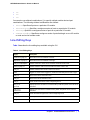
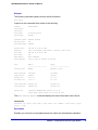
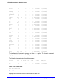
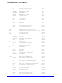
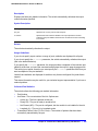
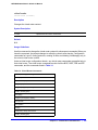
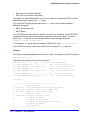
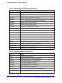
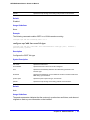
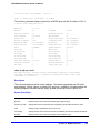
Revision History
Publication Part Number
Version
Publish Date
Comments
202-10802-01
v1.0
March 2011
First publication
2 |
Contents
Chapter 1 Command Reference Overview
Introduction. . . . . . . . . . . . . . . . . . . . . . . . . . . . . . . . . . . . . . . . . . . . . . . . . . 6
Audience . . . . . . . . . . . . . . . . . . . . . . . . . . . . . . . . . . . . . . . . . . . . . . . . . . . 6
Structure of this Guide . . . . . . . . . . . . . . . . . . . . . . . . . . . . . . . . . . . . . . . . . 7
Understanding the Command Syntax. . . . . . . . . . . . . . . . . . . . . . . . . . . . . . 7
Access Levels. . . . . . . . . . . . . . . . . . . . . . . . . . . . . . . . . . . . . . . . . . . . . . 7
Syntax Symbols . . . . . . . . . . . . . . . . . . . . . . . . . . . . . . . . . . . . . . . . . . . . 8
Syntax Helper . . . . . . . . . . . . . . . . . . . . . . . . . . . . . . . . . . . . . . . . . . . . . . 8
Object Names. . . . . . . . . . . . . . . . . . . . . . . . . . . . . . . . . . . . . . . . . . . . . . 9
Command Shortcuts. . . . . . . . . . . . . . . . . . . . . . . . . . . . . . . . . . . . . . . . 10
Port Numbering . . . . . . . . . . . . . . . . . . . . . . . . . . . . . . . . . . . . . . . . . . . . . 10
Numerical Ranges . . . . . . . . . . . . . . . . . . . . . . . . . . . . . . . . . . . . . . . . . 10
Line-Editing Keys . . . . . . . . . . . . . . . . . . . . . . . . . . . . . . . . . . . . . . . . . . . . 11
Command History. . . . . . . . . . . . . . . . . . . . . . . . . . . . . . . . . . . . . . . . . . . . 12
Chapter 2 Commands for Accessing the Switch
Chapter 3 Commands for Managing the Switch
SNMP . . . . . . . . . . . . . . . . . . . . . . . . . . . . . . . . . . . . . . . . . . . . . . . . . . . . . 57
Telnet . . . . . . . . . . . . . . . . . . . . . . . . . . . . . . . . . . . . . . . . . . . . . . . . . . . . . 58
TFTP . . . . . . . . . . . . . . . . . . . . . . . . . . . . . . . . . . . . . . . . . . . . . . . . . . . . . 58
System Redundancy with Dual Management Modules Installed . . . . . . . . 58
Power Supply Management . . . . . . . . . . . . . . . . . . . . . . . . . . . . . . . . . . . . 58
Simple Network Time Protocol . . . . . . . . . . . . . . . . . . . . . . . . . . . . . . . . . . 59
Chapter 4 Commands for Managing the NETGEAR 8800 Software
Chapter 5 Commands for Configuring Slots and Ports on a
Switch
Chapter 6 Commands for Configuring LLDP
Chapter 7 PoE Commands
Summary of PoE Software Features . . . . . . . . . . . . . . . . . . . . . . . . . . . . 300
Contents | 3
NETGEAR 8800 Chassis Switch CLI Manual
Chapter 8 Commands for Status Monitoring and Statistics
Event Management System . . . . . . . . . . . . . . . . . . . . . . . . . . . . . . . . . . . 330
sFlow Statistics. . . . . . . . . . . . . . . . . . . . . . . . . . . . . . . . . . . . . . . . . . . . . 331
RMON . . . . . . . . . . . . . . . . . . . . . . . . . . . . . . . . . . . . . . . . . . . . . . . . . . . 331
Chapter 9 VLAN Commands
Chapter 10
FDB Commands
Chapter 11
Commands for Virtual Routers
Chapter 12
Policy Manager Commands
Chapter 13
ACL Commands
Chapter 14
QoS Commands
Chapter 15
Security Commands
SSH . . . . . . . . . . . . . . . . . . . . . . . . . . . . . . . . . . . . . . . . . . . . . . . . . . . . . 554
SSL. . . . . . . . . . . . . . . . . . . . . . . . . . . . . . . . . . . . . . . . . . . . . . . . . . . . . . 554
User Authentication . . . . . . . . . . . . . . . . . . . . . . . . . . . . . . . . . . . . . . . . . 554
Denial of Service . . . . . . . . . . . . . . . . . . . . . . . . . . . . . . . . . . . . . . . . . . . 555
Chapter 16
Network Login Commands
Chapter 17
STP Commands
STP . . . . . . . . . . . . . . . . . . . . . . . . . . . . . . . . . . . . . . . . . . . . . . . . . . . . . 737
RSTP . . . . . . . . . . . . . . . . . . . . . . . . . . . . . . . . . . . . . . . . . . . . . . . . . . . . 737
MSTP . . . . . . . . . . . . . . . . . . . . . . . . . . . . . . . . . . . . . . . . . . . . . . . . . . . . 738
Spanning Tree Domains. . . . . . . . . . . . . . . . . . . . . . . . . . . . . . . . . . . . . . 738
Member VLANs . . . . . . . . . . . . . . . . . . . . . . . . . . . . . . . . . . . . . . . . . . 738
Carrier VLAN . . . . . . . . . . . . . . . . . . . . . . . . . . . . . . . . . . . . . . . . . . . . 738
Protected VLAN . . . . . . . . . . . . . . . . . . . . . . . . . . . . . . . . . . . . . . . . . . 739
STPD Modes . . . . . . . . . . . . . . . . . . . . . . . . . . . . . . . . . . . . . . . . . . . . 739
Encapsulation Modes . . . . . . . . . . . . . . . . . . . . . . . . . . . . . . . . . . . . . . 740
STP Rules and Restrictions . . . . . . . . . . . . . . . . . . . . . . . . . . . . . . . . . . . 741
4 |
Contents
Chapter 18
VRRP Commands
Chapter 19
IP Unicast Commands
Chapter 20
IPv6 Unicast Commands
Chapter 21
RIP Commands
NETGEAR 8800 Chassis Switch CLI Manual
Chapter 22 RIPng Commands
Chapter 23 OSPF Commands
OSPF Edge Mode . . . . . . . . . . . . . . . . . . . . . . . . . . . . . . . . . . . . . . . . . . 995
Chapter 24 OSPFv3 Commands
OSPF Edge Mode . . . . . . . . . . . . . . . . . . . . . . . . . . . . . . . . . . . . . . . . . 1037
Chapter 25 BGP Commands
Chapter 26 IP Multicast Commands
Chapter 27 IPv6 Multicast Commands
Chapter 28 MSDP Commands
Chapter 29 vMAN (PBN) Commands
Appendix A Configuration and Image Commands
Appendix B Troubleshooting Commands
Event Management System . . . . . . . . . . . . . . . . . . . . . . . . . . . . . . . . . . 1345
Command List
Contents
|
5
1.
Command Reference Overview
1
Introduction
This guide provides details of the command syntax for all NETGEAR 8800 Chassis Switch
commands as of Software Version 12.4.
The guide does not provide feature descriptions, explanations of the technologies, or
configuration examples. For information about the various features and technologies supported
by NETGEAR switches, see the NETGEAR 8800 User Manual.
This chapter includes the following sections:
•
Audience on page 6
•
Structure of this Guide on page 7
•
Understanding the Command Syntax on page 7
•
Port Numbering on page 10
•
Line-Editing Keys on page 11
•
Command History on page 12
Audience
This guide is intended for use by network administrators who are responsible for installing and
setting up network equipment. It assumes a basic working knowledge of the following:
•
Local area networks (LANs)
•
Ethernet concepts
•
Ethernet switching and bridging concepts
•
Routing concepts
•
Internet Protocol (IP) concepts
•
Routing Information Protocol (RIP), Open Shortest Path First (OSPF), and Intermediate
System-Intermediate System (IS-IS) concepts
•
Border Gateway Protocol (BGP-4) concepts
•
IP Multicast concepts
Chapter 1. Command Reference Overview
|
6
NETGEAR 8800 Chassis Switch CLI Manual
•
Protocol Independent Multicast (PIM) concepts
•
Simple Network Management Protocol (SNMP)
Structure of this Guide
This guide documents each NETGEAR 8800 OS command. Related commands are grouped
together and organized into chapters based on their most common usage. The chapters
reflect the organization of the NETGEAR 8800 User Manual. If a specific command is
relevant to a wide variety of functions and could be included in a number of different
chapters, we have attempted to place the command in the most logical chapter. Within each
chapter, commands appear in alphabetical order. You can use the Index of Commands to
locate specific commands if they do not appear where you expect to find them.
For each command, the following information is provided:
•
Command Syntax—The actual syntax of the command. The syntax conventions (the
use of braces, for example) are defined in the section Understanding the Command
Syntax on page 7.
•
Description—A brief one sentence summary of what the command does.
•
Syntax Description—The definition of any keywords and options used in the command.
•
Default—The defaults, if any, for this command. The default can be the default action of
the command if optional arguments are not provided, or it can be the default state of the
switch (such as for an enable/disable command).
•
Usage Guidelines—Information to help you use the command. This may include
prerequisites, prohibitions, and related commands, as well as other information.
•
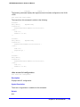
Example—Examples of the command usage, including output, if relevant.
Understanding the Command Syntax
This section covers the following topics:
•
Access Levels on page 7
•
Syntax Symbols on page 8
•
Syntax Helper on page 8
•
Object Names on page 9
•
Command Shortcuts on page 10
Access Levels
When entering a command at the prompt, ensure that you have the appropriate privilege
level. Most configuration commands require you to have the administrator privilege level.
Chapter 1. Command Reference Overview
|
7
NETGEAR 8800 Chassis Switch CLI Manual
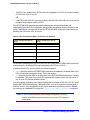
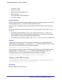
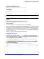
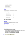
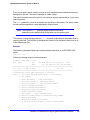
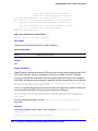
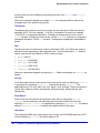
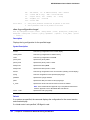
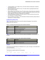
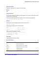
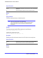
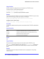
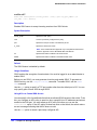
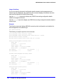
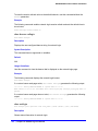
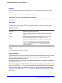
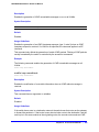
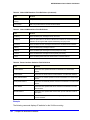
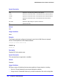
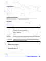
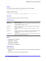
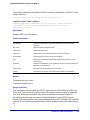
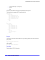
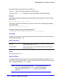
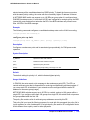
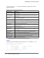
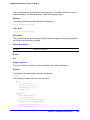
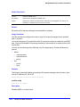
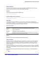
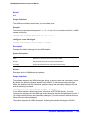
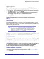
Syntax Symbols
You may see a variety of symbols shown as part of the command syntax. These symbols
explain how to enter the command, but you do not type them as part of the command itself.
Table 1 summarizes the command syntax symbols.
Note: NETGEAR 8800 software does not support the ampersand (&), left
angle bracket (<), or right angle bracket (>), because they are
reserved characters with special meaning in XML.
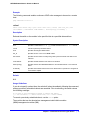
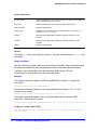
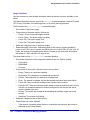
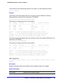
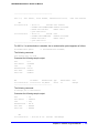
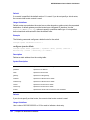
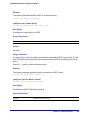
Table 1. Command Syntax Symbols
Symbol
Description
angle brackets < >
Enclose a variable or value. You must specify the variable or value. For example, in the
syntax
configure vlan <vlan_name> ipaddress <ip_address>
you must supply a VLAN name for <vlan_name> and an address for <ip_address>
when entering the command. Do not type the angle brackets and do not include spaces
within angle brackets.
square brackets [ ]
Enclose a required value or list of required arguments. One or more values or arguments
can be specified. For example, in the syntax
use image [primary | secondary]
you must specify either the primary or secondary image when entering the command. Do
not type the square brackets.
vertical bar |
Separates mutually exclusive items in a list, one of which must be entered. For example, in
the syntax
configure snmp community [readonly | readwrite]
<alphanumeric_string>
you must specify either the read or write community string in the command. Do not type
the vertical bar.
braces { }
Enclose an optional value or a list of optional arguments. One or more values or
arguments can be specified. For example, in the syntax
reboot {time <month> <day> <year> <hour> <min> <sec>} {cancel} {msm
<slot_id>} {slot <slot-number> | node-address <node-address> |
stack-topology {as-standby} }
you can specify either a particular date and time combination, or the keyword cancel to
cancel a previously scheduled reboot. (In this command, if you do not specify an
argument, the command will prompt asking if you want to reboot the switch now.) Do not
type the braces.
Syntax Helper
The CLI has a built-in syntax helper. If you are unsure of the complete syntax for a particular
command, enter as much of the command as possible and press TAB. The syntax helper
8 | Chapter 1. Command Reference Overview
NETGEAR 8800 Chassis Switch CLI Manual
provides a list of options for the remainder of the command, and places the cursor at the end
of the command you have entered so far, ready for the next option.
If the command is one where the next option is a named component, such as a VLAN,
access profile, or route map, the syntax helper also lists any currently configured names that
might be used as the next option. In situations where this list might be very long, the syntax
helper lists only one line of names, followed by an ellipses (...) to indicate that there are more
names than can be displayed.
Some values (such as the <node-address>) are lengthy, but limited in number. The
NETGEAR 8800 places these values into a “namespace.” This allows command completion
on these values.
The syntax helper also provides assistance if you have entered an incorrect command.
Abbreviated Syntax
Abbreviated syntax is the shortest unambiguous allowable abbreviation of a command or
parameter. Typically, this is the first three letters of the command. If you do not enter enough
letters to allow the switch to determine which command you mean, the syntax helper
provides a list of the options based on the portion of the command you have entered.
Note: When using abbreviated syntax, you must enter enough characters
to make the command unambiguous and distinguishable to the
switch.
Object Names
All named components within a category of the switch configuration, such as VLAN, must be
given a unique object name. Object names must begin with an alphabetical character and
may contain alphanumeric characters and underscores (_), but they cannot contain spaces.
The maximum allowed length for a name is 32 characters.
Object names can be reused across categories (for example, STPD and VLAN names). If the
software encounters any ambiguity in the components within your command, it generates a
message requesting that you clarify the object you specified.
Note: If you use the same name across categories, NETGEAR
recommends that you specify the identifying keyword as well as the
actual name. If you do not use the keyword, the system may return
an error message.
Chapter 1. Command Reference Overview
|
9
NETGEAR 8800 Chassis Switch CLI Manual
Reserved Keywords
Keywords such as vlan, stp, and other 2nd level keywords, are determined to be reserved
keywords and cannot be used as object names. This restriction applies to the specific word
(vlan) only, while expanded versions (vlan2) can be used.
A complete list of the reserved keywords for NETGEAR 8800 12.4 and later software is
displayed in Table 8 of the NETGEAR 8800 User Manual. Any keyword that is not on this list
can be used as an object name.
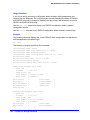
Command Shortcuts
Components are typically named using the create command. When you enter a command
to configure a named component, you do not need to use the keyword of the component. For
example, to create a VLAN, enter a VLAN name:
create vlan engineering
Once you have created the VLAN with a unique name, you can then eliminate the keyword
vlan from all other commands that require the name to be entered (unless you used the
same name for another category, such as STPD). For example, instead of entering the
command:
configure vlan engineering delete port 1:3,4:6
you could enter the following shortcut:
configure engineering delete port 1:3,4:6
Port Numbering
Commands that require you to enter one or more port numbers use the parameter
<port_list> in the syntax.
Note: The keyword all acts on all possible ports; it continues on all ports
even if one port in the sequence fails.
Numerical Ranges
On the NETGEAR 8800, the port number is a combination of the slot number and the port
number. The nomenclature for the port number is as follows:
slot:port
For example, if an I/O module that has a total of four ports is installed in slot 2 of the chassis,
the following ports are valid:
•
2:1
10 | Chapter 1. Command Reference Overview
NETGEAR 8800 Chassis Switch CLI Manual
•
2:2
•
2:3
•
2:4
You can also use wildcard combinations (*) to specify multiple modular slot and port
combinations. The following wildcard combinations are allowed:
•
slot:*—Specifies all ports on a particular I/O module.
•
slot:x-slot:y—Specifies a contiguous series of ports on a particular I/O module.
•
slot:x-y—Specifies a contiguous series of ports on a particular I/O module.
•
slota:x-slotb:y—Specifies a contiguous series of ports that begin on one I/O module
or node and end on another node.
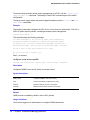
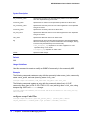
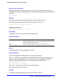
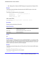
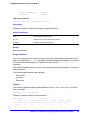
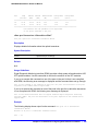
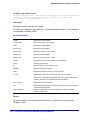
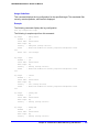
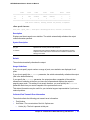
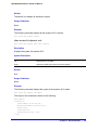
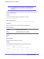
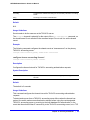
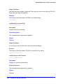
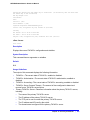
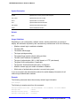
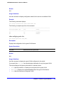
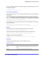
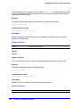
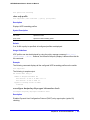
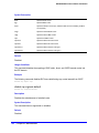
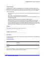
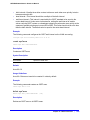
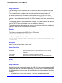
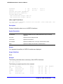
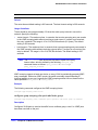
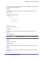
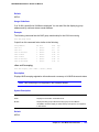
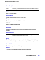
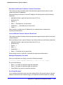
Line-Editing Keys
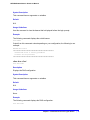
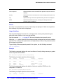
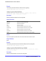
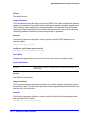
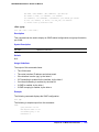
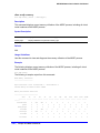
Table 2 describes the line-editing keys available using the CLI.
Table 2. Line-Editing Keys
Key(s)
Description
Left arrow or [Ctrl] + B
Moves the cursor one character to the left.
Right arrow or [Ctrl] + F
Moves the cursor one character to the right.
[Ctrl] + H or Backspace
Deletes character to left of cursor and shifts remainder of line to left.
Delete or [Ctrl] + D
Deletes character under cursor and shifts remainder of line to left.
[Ctrl] + K
Deletes characters from under cursor to end of line.
Insert
Toggles on and off. When toggled on, inserts text and shifts previous text to right.
[Ctrl] + A
Moves cursor to first character in line.
[Ctrl] + E
Moves cursor to last character in line.
[Ctrl] + L
Clears screen and movers cursor to beginning of line.
[Ctrl] + P or
Up Arrow
Displays previous command in command history buffer and places cursor at end of
command.
[Ctrl] + N or
Down Arrow
Displays next command in command history buffer and places cursor at end of
command.
[Ctrl] + U
Clears all characters typed from cursor to beginning of line.
[Ctrl] + W
Deletes previous word.
[Ctrl] + C
Interrupts the current CLI command execution.
Chapter 1. Command Reference Overview
|
11
NETGEAR 8800 Chassis Switch CLI Manual
Command History
The NETGEAR 8800 saves the commands you enter. You can display a list of these
commands by using the following command:
history
If you use a command more than once, consecutively, the history will list only the first
instance.
12 | Chapter 1. Command Reference Overview
2.
Commands for Accessing the Switch
2
This chapter describes commands used for:
•
Accessing and configuring the switch including how to set up user accounts, passwords,
date and time settings, and software licenses
•
Managing passwords
•
Configuring the Domain Name Service (DNS) client
•
Checking basic switch connectivity
•
Enabling and displaying licenses
•
Returning the switch to safe defaults mode
NETGEAR 8800 supports the following two levels of management:
•
User
•
Administrator
A user-level account has viewing access to all manageable parameters, with the exception of:
•
User account database
•
SNMP community strings
A user-level account can change the password assigned to the account name and use the ping
command to test device reachability.
An administrator-level account can view and change all switch parameters. It can also add and
delete users and change the password associated with any account name. The administrator
can disconnect a management session that has been established by way of a Telnet connection.
If this happens, the user logged on by way of the Telnet connection is notified that the session
has been terminated.
The DNS client in NETGEAR 8800 augments certain commands to accept either IP addresses
or host names. For example, DNS can be used during a Telnet session when you are accessing
a device or when using the ping command to check the connectivity of a device.
The switch offers the following commands for checking basic connectivity:
•
ping
•
traceroute
Chapter 2. Commands for Accessing the Switch
|
13
NETGEAR 8800 Chassis Switch CLI Manual
The ping command enables you to send Internet Control Message Protocol (ICMP) echo
messages to a remote IP device. The traceroute command enables you to trace the routed
path between the switch and a destination endstation.
This chapter describes commands for enabling and displaying software, security, and feature
pack licenses.
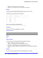
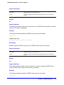
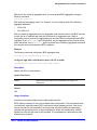
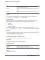
clear account lockout
clear account [all | <name>] lockout
Description
This command re-enables an account that has been locked out (disabled) for exceeding the
permitted number failed login attempts, which was configured by using the configure
account password-policy lockout-on-login-failures command.
Syntax Description
all
Specifies all users.
name
Specifies an account name.
Usage Guidelines
This command applies to sessions at the console port of the switch as well as all other
sessions. You can re-enable both user and administrative accounts, once they have been
disabled for exceeding the three failed login attempts.
Note: The failsafe accounts are never locked out.
This command clears only the locked-out (or disabled) condition of the account. The action of
locking out accounts following the failed login attempts remains until you turn it off by issuing
the configure account [all | <name>] password-policy lockout-on-login failures off
command.
Example
The following command re-enables the account finance, which had been locked out
(disabled) for exceeding 3 consecutive failed login attempts:
clear account finance lockout
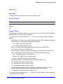
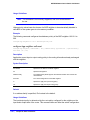
clear license-info
clear license-info
14 | Chapter 2. Commands for Accessing the Switch
NETGEAR 8800 Chassis Switch CLI Manual
Description
This command, which should be used only in conjunction with a representative from
NETGEAR, clears the licensing information from the switch.
Syntax Description
This command has no variables or parameters.
Default
N/A.
Usage Guidelines
Note: Use this command only under the guidance of an NETGEAR
representative.
This command clears licensing information from the switch. When you issue this command,
the system requests a confirmation. If you answer yes, the system sends a Warning
message to the log.
Example
The following command removes licensing information from the switch:
clear license-info
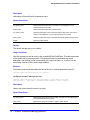
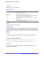
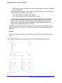
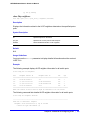
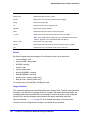
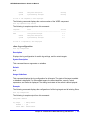
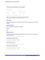
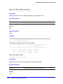
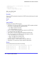
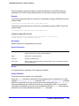
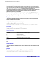
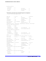
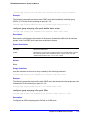
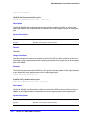
clear session
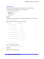
clear session [history | <sessId> | all]
Description
Terminates a Telnet and/or SSH2 sessions from the switch.
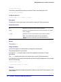
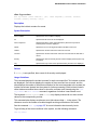
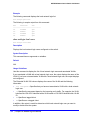
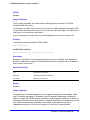
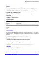
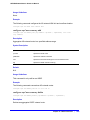
Syntax Description
Default
?
N/A.
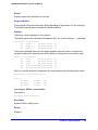
Usage Guidelines
An administrator-level account can disconnect a management session that has been
established by way of a Telnet connection. You can determine the session number of the
session you want to terminate by using the show session command. The show session output
displays information about current Telnet and/or SSH2 sessions including:
Chapter 2. Commands for Accessing the Switch
|
15
NETGEAR 8800 Chassis Switch CLI Manual
•
The session number
•
The login date and time
•
The user name
•
The type of Telnet session
•
Authentication information
Depending on the software version running on your switch, additional session information
may be displayed. The session number is the first number displayed in the show session
output.
When invoked to the clear the session history, the command clears the information about all
the previous sessions that were logged. The information about the active sessions remains
intact.
Example
The following command terminates session 4 from the system:
clear session 4
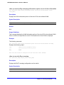
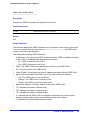
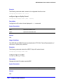
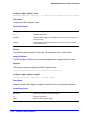
configure account
configure account [all | <name>]
Description
Configures a password for the specified account, either user account or administrative
account.
Syntax Description
all
Specifies all accounts (and future users).
name
Specifies an account name.
Default
N/A.
Usage Guidelines
You must create a user or administrative account before you can configure that account with
a password. Use the create account command to create a user account.
The system prompts you to specify a password after you enter this command. You must enter
a password for this command; passwords cannot be null and cannot include the following
characters: “<“, “>”, and “?”.
16 | Chapter 2. Commands for Accessing the Switch
NETGEAR 8800 Chassis Switch CLI Manual
Note: Once you issue this command, you cannot have a null password.
However, if you want to have a null password (that is, no password
on the specified account), use the create account command.
Passwords can have a minimum of 0 character and can have a maximum of 32 characters.
Both passwords and user names are case-sensitive.
Note: If the account is configured to require a specific password format,
the minimum is 8 characters. See configure account
password-policy char-validation for more information.
You must have administrator privileges to change passwords for accounts other than your
own.
Example
The following command defines a new password green for the account marketing:
configure account marketing
The switch responds with a password prompt:
password: green
Your keystrokes will not be echoed as you enter the new password. After you enter the
password, the switch will then prompt you to reenter it.
Reenter password: green
Assuming you enter it successfully a second time, the password is now changed.
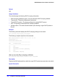
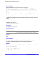
configure account encrypted
configure account [all | <name>] encrypted <e-password>
Description
Encrypts the password that is entered in plain text for the specified account, either user
account or administrative account.
Syntax Description
all
Specifies all accounts (and future users).
name
Specifies an account name.
e-password
Enter in plain text the string you for an encrypted password. See Usage
Guidelines for more information.
Chapter 2. Commands for Accessing the Switch
|
17
NETGEAR 8800 Chassis Switch CLI Manual
Default
N/A.
Usage Guidelines
You must create a user or administrative account before you can configure that account with
a password. Use the create account account command to create a user account.
When you use this command, the following password that you specify in plain text is entered
and displayed by the switch in an encrypted format. Administrators should enter the
password in plain text. The encrypted password is then used by the switch once it encrypts
the plain text password. The encrypted command should be used by the switch only to show,
store, and load a system-generated encrypted password in configuration; this applies with the
following commands: save configuration, show configuration, and use configuration.
Note: Once you issue this command, you cannot have a null password.
However, if you want to have a null password (that is, no password
on the specified account), use the create account command.
Passwords can have a minimum of 0 character and can have a maximum of 32 characters.
Both passwords and user names are case-sensitive.
Note: If the account is configured to require a specific password format,
the minimum is 8 characters. See configure account
password-policy char-validation for more information.
You must have administrator privileges to change passwords for accounts other than your
own.
Example
The following command encrypts the password red for the account marketing:
configure account marketing encrypted red
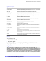
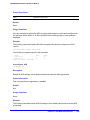
configure account password-policy char-validation
configure account [all | <name>] password-policy char-validation [none | all-char-groups]
Description
Requires that the user include an upper-case letter, a lower-case letter, a digit, and a symbol
in the password.
18 | Chapter 2. Commands for Accessing the Switch
NETGEAR 8800 Chassis Switch CLI Manual
Syntax Description
all
Specifies all users (and future users).
name
Specifies an account name.
none
Resets password to accept all formats.
all-char-groups
Specifies that the password must contain at least two characters from each of
the four groups.
Note: The password minimum length will be 8 characters if you
specify this option.
Default
N/A.
Usage Guidelines
This feature is disabled by default.
Once you issue this command, each password must include at least two characters of each
of the following four types:
•
Upper-case A-Z
•
Lower-case a-z
•
0-9
•
!, @, #, $, %, ^, *, (, )
The minimum number of characters for these specifically formatted passwords is 8
characters and the maximum is 32 characters.
Use the none option to reset the password to accept all formats.
Example
The following command requires all users to use this specified format for all passwords:
configure account all password-policy char-validation all-char-groups
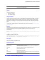
configure account password-policy history
configure account [all | <name>] password-policy history [<num_passwords> | none]
Description
Configures the switch to verify the specified number of previous passwords for the account.
The user is prevented from changing the password on a user or administrative account to
any of these previously saved passwords.
Chapter 2. Commands for Accessing the Switch
|
19
NETGEAR 8800 Chassis Switch CLI Manual
Syntax Description
all
Specifies all accounts (and future users).
name
Specifies an account name.
num_passwords
Specifies the number of previous passwords the system verifies for each
account. The range is 1 to 10 passwords.
none
Resets the system to not remember any previous passwords.
Default
N/A.
Usage Guidelines
Use this command to instruct the system to verify new passwords against a list of all
previously used passwords, once an account successfully changes a password. The limit is
the number of previous passwords that the system checks against in the record to verify the
new password.
If this parameter is configured, the system returns an error message if a user attempts to
change the password to one that is saved by the system (up to the configured limit) for that
account; this applies to both user and administrative accounts. This also applies to a
configured password on the default admin account on the switch.
The limit of previous passwords that the system checks for previous use is configurable from
1 to 10. Using the none option disables previous password tracking and returns the system to
the default state of no record of previous passwords.
Example
The following command instructs the system to verify that the new password has not been
used as a password in the previous 5 passwords for the account engineering:
configure account engineering password-policy history 5
configure account password-policy lockout-on-login-failures
configure account [all | <name>] password-policy lockout-on-login-failures [on | off]
Description
Disables an account after the user has 3 consecutive failed login attempts.
Syntax Description
all
Specifies all users (and future users).
name
Specifies an account name.
20 | Chapter 2. Commands for Accessing the Switch
NETGEAR 8800 Chassis Switch CLI Manual
on
Specifies an account name.
off
Resets the password to never lockout the user.
Default
N/A.
Usage Guidelines
If you are not working on SSH, you can configure the number of failed logins that trigger
lockout, using the configure cli max-failed-logins <num-of-logins> command.
This command applies to sessions at the console port of the switch as well as all other
sessions and to user-level and administrator-level accounts. This command locks out the
user after 3 consecutive failed login attempts; the user’s account must be specifically
re-enabled by an administrator.
Using the off option resets the account to allow innumerable consecutive failed login
attempts, which is the system default. The system default is that 3 failed consecutive login
attempts terminate the particular session, but the user may launch another session; there is
no lockout feature by default.
Note: The failsafe accounts are never locked out, no matter how many
consecutive failed login attempts.
Example
The following command enables the account finance for lockout. After 3 consecutive failed
login attempts, the account is subsequently locked out:
configure account finance password-policy lockout-on-login-failures on
configure account password-policy max-age
configure account [all | <name>] password-policy max-age [<num_days> | none]
Description
Configures a time limit for the passwords for specified accounts. The passwords for the
default admin account and the failsafe account do not age out.
Syntax Description
all
Specifies all accounts (and future users).
name
Specifies an account name.
Chapter 2. Commands for Accessing the Switch
|
21
NETGEAR 8800 Chassis Switch CLI Manual
num_days
Specifies the length of time that a password can be used. The range is 1 to
365 days.
none
Resets the password to never expire.
Default
N/A.
Usage Guidelines
The passwords for the default admin account and the failsafe account never expire.
The time limit is specified in days, from 1 to 365 days. Existing sessions are not closed when
the time limit expires; it will not open the next time the user attempts to log in.
When a user logs into an account with an expired password, the system first verifies that the
entered password had been valid prior to expiring and then prompts the user to change the
password.
Note: This is the sole time that a user with a user-level (opposed to an
administrator-level) account can make any changes to the user-level
account.
Using the none option prevents the password for the specified account from ever expiring (it
resets the password to the system default of no time limit).
Example
The following command sets a 3-month time limit for the password for the account marketing:
configure account marketing password-policy max-age 90
configure account password-policy min-length
configure account [all | <name>] password-policy min-length [<num_characters> | none]
Description
Requires a minimum number of characters for passwords.
Syntax Description
all
Specifies all accounts (and future users).
name
Specifies an account name.
22 | Chapter 2. Commands for Accessing the Switch
NETGEAR 8800 Chassis Switch CLI Manual
num_characters
Specifies the minimum number of characters required for the password. The
range is 1 to 32 characters.
Note: If you configure the configure account
password-policy char-validation parameter, the
minimum length is 8 characters.
none
Resets password to accept a minimum of 0 characters.
Note: If you configure the configure account encrypted
parameter, the minimum length is 8 characters.
Default
N/A.
Usage Guidelines
Use this command to configure a minimum length restriction for all passwords for specified
accounts. This command affects the minimum allowed length for the next password; the
current password is unaffected.
The minimum password length is configurable from 1 to 32 characters. Using the none option
disables the requirement of minimum password length and returns the system to the default
state (password minimum is 0 by default).
Note: If the account is configured to require a specific password format,
the minimum is 8 characters. See configure account
password-policy char-validation for more information.
Example
The following command requires a minimum of 8 letters for the password for the account
management:
configure account management password-policy min-length 8
configure banner
configure banner {acknowledge)
Description
Configures the banner string that is displayed at the beginning of each login prompt of each
session.
Chapter 2. Commands for Accessing the Switch
|
23
NETGEAR 8800 Chassis Switch CLI Manual
Syntax Description
acknowledge
Specifies that the system return the user-defined message after the banner is
displayed. The user must then press a key (any key) to accept before the
login displays. Certain systems require this configuration (for example, the
U.S. Department of Defense).
Default
N/A.
Usage Guidelines
Press [Return] at the beginning of a line to terminate the command and apply the banner. To
clear the banner, press [Return] at the beginning of the first line. You can enter up to 24 rows
of 79-column text that is displayed before the login prompt of each session. To disable the
acknowledgement feature, use the configure banner command omitting the acknowledge
parameter.
Note: The system does not wait for a keypress when you use SSH for
access; this only applies to the serial console login sessions and
telnet sessions.
Example
The following command adds a banner, Welcome to the switch, before the login prompt:
configure banner [Return]
Welcome to the switch
configure cli max-sessions
configure cli max-sessions <num-of-sessions>
Description
Limits number of simultaneous CLI sessions on the switch.
Syntax Description
num-of-sessions
Specifies the maximum number of concurrent sessions permitted. The range
is 1 to 16.
Default
The default is eight sessions.
24 | Chapter 2. Commands for Accessing the Switch
NETGEAR 8800 Chassis Switch CLI Manual
Usage Guidelines
The value must be greater than 0; the range is 1 to 16.
Example
The following command limits the number of simultaneous CLI sessions to ten:
configure cli max-sessions 10
configure cli max-failed-logins
configure cli max-failed-logins <num-of-logins>
Description
Establishes the maximum number of failed logins permitted before the session is terminated.
Syntax Description
num-of-logins
Specifies the maximum number of failed logins permitted; the range is 1 to 10.
Default
The default is three logins.
Usage Guidelines
The value must be greater than 0; the range is 1 to 10.
Example
The following command sets the maximum number of failed logins to five:
configure cli max-failed-logins 5
configure dns-client add
configure dns-client add [domain-suffix <domain_name> | name-server <ip_address> {vr
<vr_name>}]
Description
Adds a domain suffix to the domain suffix list or a name server to the available server list for
the DNS client.
Syntax Description
domain-suffix
Specifies adding a domain suffix.
domain_name
Specifies a domain name.
Chapter 2. Commands for Accessing the Switch
|
25
NETGEAR 8800 Chassis Switch CLI Manual
name-server
Specifies adding a name server.
ip_address
Specifies an IP address for the name server.
vr
Specifies use of a virtual router.
Note: User-created VRs are supported only on the platforms listed for this
feature in Appendix A of the NETGEAR 8800 User Manual.
vr_name
Specifies a virtual router.
Default
N/A.
Usage Guidelines
The domain suffix list can include up to six items. If the use of all previous names fails to
resolve a name, the most recently added entry on the domain suffix list will be the last name
used during name resolution. This command will not overwrite any exiting entries. If a null
string is used as the last suffix in the list, and all other lookups fail, the name resolver will
attempt to look up the name with no suffix.
Up to eight DNS name servers can be configured. The default value for the virtual router
used by the DNS client option is VR-Default.
Examples
The following command configures a domain name and adds it to the domain suffix list:
configure dns-client add domain-suffix xyz_inc.com
The following command specifies that the switch use the DNS server 10.1.2.1:
configure dns-client add name-server 10.1.2.1
The following command specifies that the switch use the virtual router Management:
configure dns-client add name-server 10.1.2.1 vr “VR-Mgmt”
configure dns-client default-domain
configure dns-client default-domain <domain_name>
Description
Configures the domain that the DNS client uses if a fully qualified domain name is not
entered.
Syntax Description
domain_name
Specifies a default domain name.
26 | Chapter 2. Commands for Accessing the Switch
NETGEAR 8800 Chassis Switch CLI Manual
Default
N/A.
Usage Guidelines
The default domain name will be used to create a fully qualified host name when a domain
name is not specified. For example, if the default domain name is set to “food.com” then when
a command like “ping dog” is entered, the ping will actually be executed as “ping
dog.food.com”.
Example
The following command configures the default domain name for the server:
configure dns-client default-domain xyz_inc.com
configure dns-client delete
configure dns-client delete [domain-suffix <domain_name> | name-server <ip_address> {vr
<vr_name>}]
Description
Deletes a domain suffix from the domain suffix list or a name server from the available server
list for the DNS client.
Syntax Description
domain-suffix
Specifies deleting a domain suffix.
domain_name
Specifies a domain name.
name-server
Specifies deleting a name server.
ip_address
Specifies an IP address for the name server.
vr
Specifies deleting a virtual router.
Note: User-created VRs are supported only on the platforms listed for this
feature in Appendix A of the NETGEAR 8800 User Manual.
vr_name
Specifies a virtual router.
Default
N/A.
Usage Guidelines
Specifying a domain suffix removes an entry from the domain suffix list. If the deleted item
was not the last entry in the list, all items that had been added later are moved up in the list. If
no entries in the list match the domain name specified, an error message will be displayed.
Chapter 2. Commands for Accessing the Switch
|
27
NETGEAR 8800 Chassis Switch CLI Manual
The default value for the virtual router used by the DNS client option is VR-Default.
Examples
The following command deletes a domain name from the domain suffix list:
configure dns-client delete domain-suffix xyz_inc.com
The following command removes a DNS server from the list:
configure dns-client delete name-server 10.1.2.1
configure failsafe-account
configure failsafe-account {[deny | permit] [all | control | serial | ssh
{vr <vr-name>} | telnet {vr <vr-name>}]}
Description
Configures a name and password for the failsafe account, or restricts access to specified
connection types.
Syntax Description
deny
Prohibits failsafe account usage over the specified connection type(s).
permit
Allows a failsafe account to be used over the specified connection type(s).
all
Specifies all connection types.
control
Specifies internal access between nodes in a NETGEAR 8800 or between
MSMs/MMs in a chassis.
serial
Specifies access over the switch console port.
ssh
Specifies access using SSH on specified or all virtual routers.
telnet
Specifies access using Telnet on specified or all virtual routers.
Default
The failsafe account is always configured. The default connection types over which failsafe
account access is permitted are the same as if “permit all” is configured.
Usage Guidelines
The failsafe account is the account of last resort to access your switch.
If you use the command with no parameters, you are prompted for the failsafe account name
and prompted twice to specify the password for the account. The password does not appear
on the display at any time. You are not required to know the current failsafe account and
password in order to change it.
28 | Chapter 2. Commands for Accessing the Switch
NETGEAR 8800 Chassis Switch CLI Manual
If you use the command with the permit or deny parameter, the permitted connection types
are altered as specified.
The failsafe account or permitted connection types are immediately saved to NVRAM on all
MSMs/MMs or active nodes.
Note: The information that you use to configure the failsafe account
cannot be recovered by NETGEAR. Technical support cannot
retrieve passwords or account names for this account. Protect this
information carefully.
Once you enter the failsafe account name, you are prompted to enter the password. Once
you successfully log in to the failsafe account, you are logged in to an admin-level account.
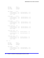
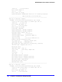
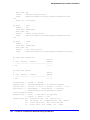
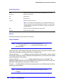
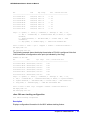
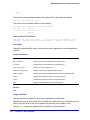
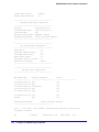
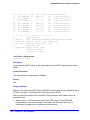
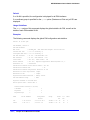
Example
The following command changes the failsafe account: username to blue5green and the
password to red5yellow.
XCM8806.1 # configure failsafe-account
enter failsafe user name: blue5green
enter failsafe password:
enter password again:
XCM8806.2
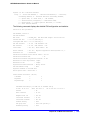
The following example restricts usage of the failsafe account to the series console port and to
access between MSMs.
XCM8810.1 # configure failsafe-account deny all
XCM8810.2 # configure failsafe-account permit serial
XCM8810.3 # configure failsafe-account permit control
XCM8810.4 #
configure idletimeout
configure idletimeout <minutes>
Description
Configures the time-out for idle console, SSH2, and Telnet sessions.
Syntax Description
minutes
Specifies the time-out interval, in minutes. Range is 1 to 240 (1 minute to 4
hours).
Chapter 2. Commands for Accessing the Switch
|
29
NETGEAR 8800 Chassis Switch CLI Manual
Default
The default time-out is 20 minutes.
Usage Guidelines
This command configures the length of time the switch will wait before disconnecting idle
console, SSH2, or Telnet sessions. The idletimeout feature must be enabled for this
command to have an effect (the idletimeout feature is enabled by default).
Example
The following command sets the time-out for idle login and console sessions to 10 minutes:
configure idletimeout 10
configure safe-default-script
configure safe-default-script
Description
Allows you to change management access to your device and to enhance security.
Syntax Description
This command has no arguments or variables.
Default
N/A.
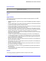
Usage Guidelines
This command runs an interactive script that prompts you to choose to enable or disable
SNMP, Telnet, and enabled ports. Refer to the “Safe Defaults Setup Method” section in the
NETGEAR 8800 User Manual for complete information on the safe default mode.
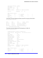
Once you issue this command, the system presents you with the following interactive script:
Telnet is enabled by default. Telnet is unencrypted and has been the target of
security exploits in the past.
Would you like to disable Telnet? [y/N]:
SNMP access is enabled by default. SNMP uses no encryption, SNMPv3 can be
configured to eliminate this problem.
Would you like to disable SNMP? [y/N]:
All ports are enabled by default. In some secure applications, it maybe more
30 | Chapter 2. Commands for Accessing the Switch
NETGEAR 8800 Chassis Switch CLI Manual
desirable for the ports to be turned off.
Would you like unconfigured ports to be turned off by default? [y/N]:
Changing the default failsafe account username and password is highly
recommended.
If you choose to do so, please remember the username and
password as this information cannot be recovered by NETGEAR.
Would you like to change the failsafe account username and password
now? [y/N]:
Would you like to permit failsafe account access via the management port?
[y/N]:
Since you have chosen less secure management methods, please remember to
increase the security of your network by taking the following actions:
* change your admin password
* change your failsafe account username and password
* change your SNMP public and private strings
* consider using SNMPv3 to secure network management traffic
Example
The following command reruns the interactive script to configure management access:
configure safe-default-script
configure time
configure time <month> <day> <year> <hour> <min> <sec>
Description
Configures the system date and time.
Syntax Description
month
Specifies the month. The range is 1-12.
day
Specifies the day of the month. The range is 1-31.
year
Specifies the year in the YYYY format.The range is 2003 to 2036.
hour
Specifies the hour of the day. The range is 0 (midnight) to 23 (11 pm).
min
Specifies the minute. The range is 0-59.
sec
Specifies the second. The range is 0-59.
Chapter 2. Commands for Accessing the Switch
|
31
NETGEAR 8800 Chassis Switch CLI Manual
Default
N/A.
Usage Guidelines
The format for the system date and time is as follows:
mm dd yyyy hh mm ss
The time uses a 24-hour clock format. You cannot set the year earlier than 2003 or past 2036.
You have the choice of inputting the entire time/date string. If you provide one item at a time
and press TAB, the screen prompts you for the next item. Press <cr> to complete the input.
Example
The following command configures a system date of February 15, 2002 and a system time of
8:42 AM and 55 seconds:
configure time 02 15 2002 08 42 55
configure timezone
configure timezone {name <tz_name>} <GMT_offset>
{autodst {name <dst_timezone_ID>} {<dst_offset>}
{begins [every <floatingday> | on <absoluteday>] {at <time_of_day>}
{ends [every <floatingday> | on <absoluteday>] {at <time_of_day>}}}
| noautodst}
Description
Configures the Greenwich Mean Time (GMT) offset and Daylight Saving Time (DST)
preference.
Syntax Description
tz_name
Specifies an optional name for this timezone specification. May be up to six
characters in length. The default is an empty string.
GMT_offset
Specifies a Greenwich Mean Time (GMT) offset, in + or - minutes.
autodst
Enables automatic Daylight Saving Time.
dst-timezone-ID
Specifies an optional name for this DST specification. May be up to six
characters in length. The default is an empty string.
dst_offset
Specifies an offset from standard time, in minutes. Value is in the range of 1
to 60. Default is 60 minutes.
32 | Chapter 2. Commands for Accessing the Switch
NETGEAR 8800 Chassis Switch CLI Manual
floatingday
Specifies the day, week, and month of the year to begin or end DST each
year. Format is:
<week> <day> <month> where:
• <week> is specified as [first | second | third | fourth | last] or 1-5.
• <day> is specified as [sunday | monday | tuesday | wednesday | thursday
| friday | saturday] or 1-7 (where 1 is Sunday).
• <month> is specified as [january | february | march | april | may | june | july
| august | september | october | november | december] or 1-12.
Default for beginning is second sunday march; default for ending is first
sunday november.
absoluteday
Specifies a specific day of a specific year on which to begin or end DST.
Format is:
<month> <day> <year> where:
• <month> is specified as 1-12.
• <day> is specified as 1-31.
• <year> is specified as 2003-2035.
The year must be the same for the begin and end dates.
time_of_day
Specifies the time of day to begin or end Daylight Saving Time. May be
specified as an hour (0-23) or as hour:minutes. Default is 2:00.
noautodst
Disables automatic Daylight Saving Time.
Default
Autodst, beginning every second Sunday in March, and ending every first Sunday in
November.
Usage Guidelines
Network Time Protocol (NTP) server updates are distributed using GMT time. To properly
display the local time in logs and other timestamp information, the switch should be
configured with the appropriate offset to GMT based on geographic location.
The gmt_offset is specified in +/- minutes from the GMT time.
Automatic DST changes can be enabled or disabled. The default configuration, where DST
begins on the second Sunday in March at 2:00 AM and ends the first Sunday in November at
2:00 AM, applies to most of North America (beginning in 2007), and can be configured with
the following syntax:
configure timezone <gmt_offst> autodst.
The starting and ending date and time for DST may be specified, as these vary in time zones
around the world.
•
Use the every keyword to specify a year-after-year repeating set of dates (for example,
the last Sunday in March every year)
•
Use the on keyword to specify a non-repeating, specific date for the specified year. If you
use this option, you will need to specify the command again every year.
•
The begins specification defaults to every second sunday march.
Chapter 2. Commands for Accessing the Switch
|
33
NETGEAR 8800 Chassis Switch CLI Manual
•
The ends specification defaults to every first sunday november.
•
The ends date may occur earlier in the year than the begins date. This will be the case for
countries in the Southern Hemisphere.
•
If you specify only the starting or ending time (not both) the one you leave unspecified will
be reset to its default.
•
The time_of_day specification defaults to 2:00.
•
The timezone IDs are optional. They are used only in the display of timezone
configuration information in the show switch command.
To disable automatic DST changes, re-specify the GMT offset using the noautodst option:
configure timezone <gmt_offst> noautodst.
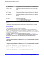
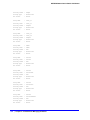
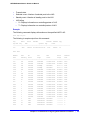
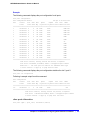
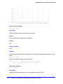
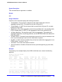
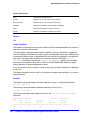
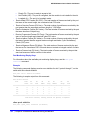
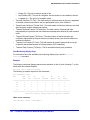
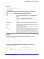
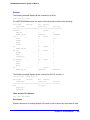
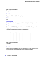
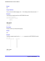
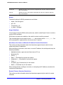
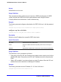
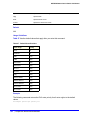
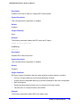
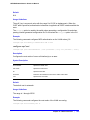
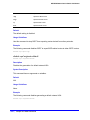
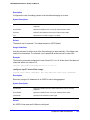
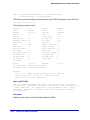
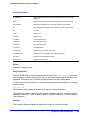
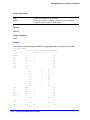
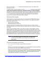
NTP updates are distributed using GMT time. To properly display the local time in logs and
other timestamp information, the switch should be configured with the appropriate offset to
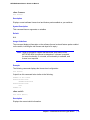
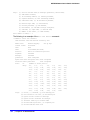
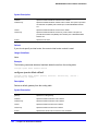
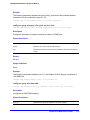
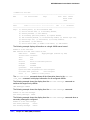
GMT based on geographical location. Table 3 describes the GMT offsets.
Table 3. Greenwich Mean Time offsets
GMT Offset GMT Offset Common Time Zone References
in Hours
in Minutes
Cities
+0:00
+0
GMT - Greenwich Mean
UT or UTC - Universal (Coordinated)
WET - Western European
London, England; Dublin, Ireland;
Edinburgh, Scotland; Lisbon, Portugal;
Reykjavik, Iceland; Casablanca,
Morocco
-1:00
-60
WAT - West Africa
Cape Verde Islands
-2:00
-120
AT - Azores
Azores
-3:00
-180
-4:00
-240
AST - Atlantic Standard
Caracas; La Paz
-5:00
-300
EST - Eastern Standard
Bogota, Columbia; Lima, Peru; New
York, NY, Trevor City, MI USA
-6:00
-360
CST - Central Standard
Mexico City, Mexico
-7:00
-420
MST - Mountain Standard
Saskatchewan, Canada
-8:00
-480
PST - Pacific Standard
Los Angeles, CA, Cupertino, CA,
Seattle, WA USA
-9:00
-540
YST - Yukon Standard
-10:00
-600
AHST - Alaska-Hawaii Standard
CAT - Central Alaska
HST - Hawaii Standard
-11:00
-660
NT - Nome
-12:00
-720
IDLW - International Date Line West
Brasilia, Brazil; Buenos Aires,
Argentina; Georgetown, Guyana;
34 | Chapter 2. Commands for Accessing the Switch
NETGEAR 8800 Chassis Switch CLI Manual
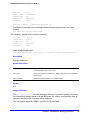
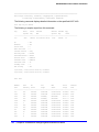
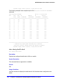
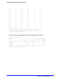
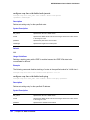
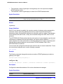
Table 3. Greenwich Mean Time offsets (Continued)
GMT Offset GMT Offset Common Time Zone References
in Hours
in Minutes
Cities
+1:00
+60
CET - Central European
FWT - French Winter
MET - Middle European
MEWT - Middle European Winter
SWT - Swedish Winter
Paris, France; Berlin, Germany;
Amsterdam, The Netherlands;
Brussels, Belgium; Vienna, Austria;
Madrid, Spain; Rome, Italy; Bern,
Switzerland; Stockholm, Sweden; Oslo,
Norway
+2:00
+120
EET - Eastern European, Russia Zone 1
Athens, Greece; Helsinki, Finland;
Istanbul, Turkey; Jerusalem, Israel;
Harare, Zimbabwe
+3:00
+180
BT - Baghdad, Russia Zone 2
Kuwait; Nairobi, Kenya; Riyadh, Saudi
Arabia; Moscow, Russia; Tehran, Iran
+4:00
+240
ZP4 - Russia Zone 3
Abu Dhabi, UAE; Muscat; Tblisi;
Volgograd; Kabul
+5:00
+300
ZP5 - Russia Zone 4
+5:30
+330
IST – India Standard Time
+6:00
+360
ZP6 - Russia Zone 5
+7:00
+420
WAST - West Australian Standard
+8:00
+480
CCT - China Coast, Russia Zone 7
+9:00
+540
JST - Japan Standard, Russia Zone 8
+10:00
+600
EAST - East Australian Standard
GST - Guam Standard
Russia Zone 9
+11:00
+660
+12:00
+720
IDLE - International Date Line East
NZST - New Zealand Standard
NZT - New Zealand
New Delhi, Pune, Allahabad, India
Wellington, New Zealand; Fiji, Marshall
Islands
For name creation guidelines and a list of reserved names, see the section “Object Names”
in the NETGEAR 8800 User Manual.
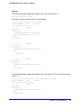
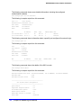
Example
The following command configures GMT offset for Mexico City, Mexico and disables
automatic DST:
configure timezone -360 noautodst
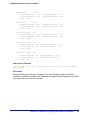
The following four commands are equivalent, and configure the GMT offset and automatic
DST adjustment for the US Eastern timezone, with an optional timezone ID of EST:
Chapter 2. Commands for Accessing the Switch
|
35
NETGEAR 8800 Chassis Switch CLI Manual
configure timezone name EST -300 autodst name EDT 60 begins every second sunday march at 2:00
ends every first sunday november at 2:00
configure timezone name EST -300 autodst name EDT 60 begins every 1 1 4 at 2:00 ends every 5
1 10 at 2:00
configure timezone name EST -300 autodst name EDT
configure timezone -300 autodst
The following command configures the GMT offset and automatic DST adjustment for the
Middle European timezone, with the optional timezone ID of MET:
configure timezone name MET 60 autodst name MDT begins every last sunday march at 1 ends every
last sunday october at 1
The following command configures the GMT offset and automatic DST adjustment for New
Zealand. The ending date must be configured each year because it occurs on the first
Sunday on or after March 5:
configure timezone name NZST 720 autodst name NZDT 60 begins every first sunday october at 2
ends on 3/16/2002 at 2
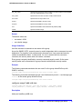
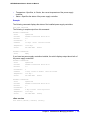
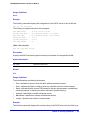
create account
create account [admin | user] <account-name> {encrypted <password>}
Description
Creates a new user account.
Syntax Description
admin
Specifies an access level for account type admin.
user
Specifies an access level for account type user.
account-name
Specifies a new user account name. See Usage Guidelines for more
information.
encrypted
Specifies the encrypted option.
password
Specifies a user password. See Usage Guidelines for more information.
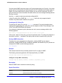
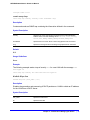
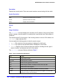
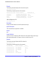
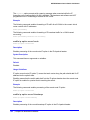
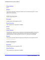
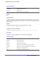
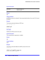
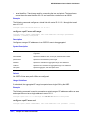
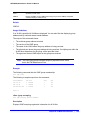
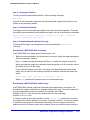
Default
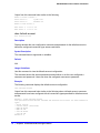
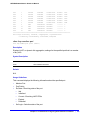
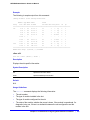
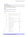
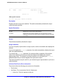
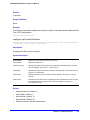
By default, the switch is configured with two accounts with the access levels shown in
Table 4.
36 | Chapter 2. Commands for Accessing the Switch
NETGEAR 8800 Chassis Switch CLI Manual
Table 4. User account levels
Account Name
Access Level
admin
This user can access and change all manageable parameters. The admin account
cannot be deleted.
user
This user can view (but not change) all manageable parameters, with the following
exceptions:
• This user cannot view the user account database.
• This user cannot view the SNMP community strings.
• This user cannot view SSL settings.
This user has access to the ping command.
You can use the default names (admin and user), or you can create new names and
passwords for the accounts. Default accounts do not have passwords assigned to them. For
name creation guidelines and a list of reserved names, see the section “Object Names” in the
NETGEAR 8800 User Manual.
Usage Guidelines
The switch can have a total of 16 user accounts. The system must have one administrator
account.
When you use the encrypted keyword, the following password that you specify in plain text is
entered and displayed by the switch in an encrypted format. Administrators should not use
the encrypted option and should enter the password in plain text. The encrypted option is
used by the switch after encrypting the plain text password. The encrypted option should be
used by the switch only to show, store, and load a system-generated encrypted password in
configuration; this applies with the following commands: save configuration, show
configuration, and use configuration.
The system prompts you to specify a password after you enter this command and to reenter
the password. If you do not want a password associated with the specified account, press
Enter twice.
You must have administrator privileges to change passwords for accounts other than your
own. User names and passwords are case-sensitive. User account names must have a
minimum of 1 character and can have a maximum of 32 characters. Passwords must have a
minimum of 0 characters and can have a maximum of 32 characters.
Note: If the account is configured to require a specific password format,
the minimum is 8 characters. See configure account
password-policy char-validation for more information.
Example
The following command creates a new account named John2 with administrator privileges:
Chapter 2. Commands for Accessing the Switch
|
37
NETGEAR 8800 Chassis Switch CLI Manual
create account admin John2
delete account
delete account <name>
Description
Deletes a specified user account.
Syntax Description
name
Specifies a user account name.
Default
N/A.
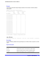
Usage Guidelines
Use the show accounts command to determine which account you want to delete from the
system. The show accounts output displays the following information in a tabular format:
•
The user name
•
Access information associated with each user
•
User login information
•
Session information
Depending on the software version running on your switch and the type of switch you have,
additional account information may be displayed.
You must have administrator privileges to delete a user account. The system must have one
administrator account; the command will fail if an attempt is made to delete the last
administrator account on the system.
To ensure security, change the password on the default account, but do not delete it. The
changed password will remain intact through configuration uploads and downloads.
If you must delete the default account, first create another administrator-level account.
Example
The following command deletes account John2:
delete account John2
disable cli space-completion
disable cli space-completion
38 | Chapter 2. Commands for Accessing the Switch
NETGEAR 8800 Chassis Switch CLI Manual
Description
Disables the NETGEAR 8800 feature that completes a command automatically with the
spacebar. If you disable this feature, you can still use the TAB key for auto-completion.
Syntax Description
This command has no arguments or variables.
Default
Disabled.
Usage Guidelines
None.
Example
The following command disables using the spacebar to automatically complete a command:
disable cli space-completion
disable clipaging
disable clipaging
Description
Disables pausing at the end of each show screen.
Syntax Description
This command has no arguments or variables.
Default
Enabled.
Usage Guidelines
The command line interface (CLI) is designed for use in a VT100 environment. Most show
command output will pause when the display reaches the end of a page. This command
disables the pause mechanism and allows the display to print continuously to the screen.
CLI paging is only active on a per-shell session basis. In other words, when you enable or
disable CLI paging from within the current configuration, it only affects that session. For new
or existing sessions, paging is enabled by default. This setting cannot be saved.
To view the status of CLI paging on the switch, use the show management command. The show
management command displays information about the switch including the enable/disable
state for CLI paging.
Chapter 2. Commands for Accessing the Switch
|
39
NETGEAR 8800 Chassis Switch CLI Manual
Example
The following command disables clipaging and allows you to print continuously to the screen:
disable clipaging
disable idletimeout
disable idletimeout
Description
Disables the timer that disconnects idle sessions from the switch.
Syntax Description
This command has no arguments or variables.
Default
Enabled. Timeout 20 minutes.
Usage Guidelines
When idle time-outs are disabled, console sessions remain open until the switch is rebooted
or until you logoff. Telnet sessions remain open until you close the Telnet client.
If you have an SSH2 session and disable the idle timer, the SSH2 connection times out after
61 minutes of inactivity.
To view the status of idle time-outs on the switch, use the show management command. The
show management command displays information about the switch including the
enable/disable state for idle time-outs.
Example
The following command disables the timer that disconnects all sessions to the switch:
disable idletimeout
enable cli space-completion
enable cli space-completion
Description
Enables the NETGEAR 8800 feature that completes a command automatically with the
spacebar. You can also use the TAB key for auto-completion.
Syntax Description
This command has no arguments or variables.
40 | Chapter 2. Commands for Accessing the Switch
NETGEAR 8800 Chassis Switch CLI Manual
Default
Disabled.
Usage Guidelines
None.
Example
The following command enables using the spacebar to automatically complete a command:
enable cli space-completion
enable clipaging
enable clipaging
Description
Enables the pause mechanism and does not allow the display to print continuously to the
screen.
Syntax Description
This command has no arguments or variables.
Default
Enabled.
Usage Guidelines
The command line interface (CLI) is designed for use in a VT100 environment. Most show
command output will pause when the display reaches the end of a page.
To view the status of CLI paging on the switch, use the show management command. The show
management command displays information about the switch including the enable/disable
state for CLI paging.
If CLI paging is enabled and you use the show tech command to diagnose system technical
problems, the CLI paging feature is disabled.
CLI paging is only active on a per-shell session basis. In other words, when you enable or
disable CLI paging from within the current configuration, it only affects that session. For new
or existing sessions, paging is enabled by default. This setting cannot be saved.
Example
The following command enables clipaging and does not allow the display to print
continuously to the screen:
enable clipaging
Chapter 2. Commands for Accessing the Switch
|
41
NETGEAR 8800 Chassis Switch CLI Manual
enable idletimeout
enable idletimeout
Description
Enables a timer that disconnects Telnet, SSH2, and console sessions after a period of
inactivity (20 minutes is default).
Syntax Description
This command has no arguments or variables.
Default
Enabled. Timeout 20 minutes.
Usage Guidelines
You can use this command to ensure that a Telnet, Secure Shell (SSH2), or console session
is disconnected if it has been idle for the required length of time. This ensures that there are
no hanging connections.
To change the period of inactivity that triggers the timeout for a Telnet, SSH2, or console
session, use the configure timezone command.
To view the status of idle timeouts on the switch, use the show management command. The
show management command displays information about the switch including the
enable/disable state for idle timeouts. You can configure the length of the timeout interval.
Example
The following command enables a timer that disconnects any Telnet, SSH2, and console
sessions after 20 minutes of inactivity:
enable idletimeout
enable license software
enable license {software} <key>
Description
Enables software license or feature pack that allows you to use advanced features.
Syntax Description
key
Specifies your hexadecimal license key in format xxxx-xxxx-xxxx-xxxx-xxxx.
42 | Chapter 2. Commands for Accessing the Switch
NETGEAR 8800 Chassis Switch CLI Manual
Default
N/A
Usage Guidelines
The software license levels that apply to NETGEAR 8800 software are described in Appendix
A of the NETGEAR 8800 User Manual.
To obtain a software license, specify the key in the format xxxx-xxxx-xxxx-xxxx-xxxx.
You obtain the software license key (or feature pack key) either by ordering it from the factory
or by obtaining a license voucher from your NETGEAR supplier. You can obtain a regular
software license or a trial software license, which allows you use of the license for either 30,
60 or 90 days; you cannot downgrade software licenses.
The voucher contains all the necessary information on the software license, whether regular
or trial, and number of days for trial software license.
After you enable the software license or feature pack by entering the software key, the
system returns a message that you either successfully or unsuccessfully set the license.
Once you enable the software license (or if you do not use the correct key, attempt to
downgrade the license, or already installed the software license) you see one of the following
messages:
Enabled license successfully.
Error: Unable to set license using supplied key.
Error: Unable to set license - downgrade of licenses is not supported.
Error: Unable to set license - license is already enabled.
Error: Unable to set license - trial license already enabled.
If you enable a trial license, the system generates a daily message showing the number of
days until expiry.
Once installed (or enabled), the software license goes with the switch chassis itself (not with
the MSM/MM module). The software license information is stored in EEPROM; the
information persists through reboots, software upgrades, power outages, and
reconfigurations.
If you attempt to execute a command and you do not either have the required software
license or have reached the limits defined by the current software license level, the system
returns one of the following messages:
Error: This command cannot be executed at the current license level.
Error: You have reached the maximum limit for this feature at this license level.
If you attempt to execute a command and you do not have the required feature pack, the
system also returns a message.
To protect against attacks to install maliciously created license keys, the system has an
exponential delay of each failed attempt to install a license.
To view the type of software license you are currently running on the switch, use the show
licenses command. The license key number is not displayed, but the type of software
Chapter 2. Commands for Accessing the Switch
|
43
NETGEAR 8800 Chassis Switch CLI Manual
license is displayed in the show licenses output. This command can be run on any node in a
NETGEAR 8800, regardless of its node role (Master, Standby, or Backup).
Example
The following command enables a software license on the switch:
enable license 2d5e-0e84-e87d-c3fe-bfff
enable license file
enable license file <filename>
Description
Enables the text file that applies software licenses and feature packs licenses to more than
one switch at a time.
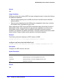
Syntax Description
fileneame
Specifies the filename that you download onto the switch using TFTP; the file
extension is .xlic.
Default
N/A
Usage Guidelines
You download the license file to the switch using TFTP or SCP. The file name extension for
this file is <xlic>; for example, you may see a file named systemlic.xlic.
Using this file, you enable the software and feature pack licenses for more than one switch
simultaneously. The file can contain licenses for some or all of the NETGEAR switches that
the customer owns. During upload, only those license keys destined for the specific switch
are used to attempt enabling the licenses. The license file is a text file that has the switch
serial number, software license type, and license key; it is removed from the switch after the
licenses are enabled.
After you enable the license file, the system returns one or more of the following messages:
Enabled license successfully.
Error: Unable to set license <license_name> using supplied key.
Error: Unable to set license <license_name> - downgrade of licenses is not supported.
Error: Unable to set license <license_name> - license is already enabled.
Error: Unable to set license <license_name> - trial license already enabled.
To protect against attacks to install maliciously created license keys, the system has an
exponential delay of each failed attempt to install a license.
44 | Chapter 2. Commands for Accessing the Switch
NETGEAR 8800 Chassis Switch CLI Manual
Example
The following command enables a license file on the specified NETGEAR switches:
enable license file santaclara.xlic
history
history
Description
Displays a list of all the commands entered on the switch.
Syntax Description
This command has no arguments or variables.
Default
N/A.
Usage Guidelines
NETGEAR 8800 saves the commands you entered on the switch. Use the history command
to display a list of these commands.
Example
The following command displays all the commands entered on the switch:
history
If you use a command more than once consecutively, the history will list only the first
instance.
ping
ping {count <count> {start-size <start-size>} | continuous {start-size <start-size>} |
{start-size <start-size> {end-size <end-size>}}} {udp} {dont-fragment} {ttl <ttl>} {tos
<tos>} {interval <interval>} {vr <vrid>} {ipv4 <host> | ipv6 <host>} {from} {with
record-route}
Description
Enables you to send User Datagram Protocol (UDP) or Internet Control Message Protocol
(ICMP) echo messages or to a remote IP device.
Syntax Description
count
Specifies the number of ping requests to send.
Chapter 2. Commands for Accessing the Switch
|
45
NETGEAR 8800 Chassis Switch CLI Manual
start-size
Specifies the size, in bytes, of the packet to be sent, or the starting size if
incremental packets are to be sent.
continuous
Specifies that UDP or ICMP echo messages to be sent continuously. This
option can be interrupted by pressing [Ctrl} + C.
end-size
Specifies an end size for packets to be sent.
udp
Specifies that the ping request should use UDP instead of ICMP.
dont-fragment
Sets the IP to not fragment the bit.
ttl
Sets the TTL value.
tos
Sets the TOS value.
interval
Sets the time interval between sending out ping requests.
vr
Specifies the virtual route to use for sending out the echo message. If not
specified, VR-Default is used.
Note: User-created VRs are supported only on the platforms
listed for this feature in Appendix A of the NETGEAR 8800 User
Manual.
ipv4
Specifies IPv4 transport.
ipv6
Specifies IPv6 transport.
Note: If you are contacting an IPv6 link local address, you must
specify the VLAN you are sending the message from: ping
<ipv6> <link-local address> %<vlan_name> <host>.
host
Specifies a host name or IP address (either v4 or v6).
from
Uses the specified source address. If not specified, the address of the
transmitting interface is used.
with record-route
Sets the traceroute information.
Default
N/A.
Usage Guidelines
The ping command is used to test for connectivity to a specific host.
You use the ipv6 variable to ping an IPv6 host by generating an ICMPv6 echo request
message and sending the message to the specified address. If you are contacting an IPv6
link local address, you must specify the VLAN you sending the message from, as shown in
the following example (you must include the % sign): ping <ipv6> <link-local address>
%<vlan_name> <host>.
The ping command is available for both the user and administrator privilege level.
46 | Chapter 2. Commands for Accessing the Switch
NETGEAR 8800 Chassis Switch CLI Manual
Example
The following command enables continuous ICMP echo messages to be sent to a remote
host:
ping continuous 123.45.67.8
reboot
reboot {time <month> <day> <year> <hour> <min> <sec>} {cancel} {msm <slot_id>} {slot
<slot-number> | node-address <node-address> | stack-topology {as-standby} }
Description
Reboots the switch or the module in the specified slot at a specified date and time.
Syntax Description
time
Specifies a reboot date in mm dd yyyy format and reboot time in hh mm ss format.
cancel
Cancels a previously scheduled reboot.
msm
Specifies rebooting the MSM module.
slot_id
Specifies the slot--A or B--for an MSM module.
slot-number
Specifies the slot number currently being used by the active stack node that is to be
rebooted
node-address
Specifies the MAC address of the node to be rebooted
stack-topology
Specifies that the entire NETGEAR 8800 is to be rebooted whether or not nodes are
active
as-standby
Specifies that all stack nodes that are to be rebooted are to operate as if configured to
not be master-capable
Default
N/A.
Usage Guidelines
If you do not specify a reboot time, the switch will reboot immediately following the command,
and any previously scheduled reboots are cancelled. Prior to rebooting, the switch returns
the following message:
Do you want to save configuration changes to primary and reboot?
(y - save and reboot, n - reboot without save, <cr> - cancel command)
To cancel a previously scheduled reboot, use the cancel option.
The modules that can be rebooted are management switch fabric modules
(MSM)/management modules (MM).
Chapter 2. Commands for Accessing the Switch
|
47
NETGEAR 8800 Chassis Switch CLI Manual
On the NETGEAR 8800 series switches, if your default BootROM image becomes corrupted,
you can force the MSM to boot from an alternate BootROM image by inserting a sharp object
into the “A” and “R” holes on the MSM and applying slight pressure. Refer to the hardware
documentation for information on the MSM.
The reboot MSM option on the 8800 series switches affects the entire module.
Example
The following command reboots the switch at 8:00 AM on April 15, 2005:
reboot time 04 15 2005 08 00 00
show accounts
show accounts
Description
Displays user account information for all users on the switch.
Syntax Description
This command has no arguments or variables.
Default
N/A.
Usage Guidelines
You need to create a user account using the create account command before you can
display user account information.
To view the accounts that have been created, you must have administrator privileges.
The show accounts command displays the following information in a tabular format:
•
User Name—The name of the user. This list displays all of the users who have access to
the switch.
•
Access—This may be listed as R/W for read/write or RO for read only.
•
Login OK—The number of logins that are okay.
•
Failed—The number of failed logins.
•
Accounts locked out—Account configured to be locked out after 3 consecutive failed login
attempts (using the configure account password-policy lockout-on-login-failures
command).
Note: This command does not show the failsafe account.
48 | Chapter 2. Commands for Accessing the Switch
NETGEAR 8800 Chassis Switch CLI Manual
Example
The following command displays user account information on the switch:
show accounts pppuser
Output from this command looks similar to the following:
User Name
Access LoginOK
Failed
---------------- ------ -------
------
admin
R/W
3
1
user
RO
0
0
dbackman
R/W
0
0
ron*
RO
0
0
nocteam
RO
0
0
---------------------------------------(*) - Account locked
show accounts password-policy
show accounts password-policy
Description
Displays password policy information for all users on the switch.
Syntax Description
This command has no arguments or variables.
Default
N/A.
Usage Guidelines
To view the password management information, you must have administrator privileges.
The show accounts password-policy command displays the following information in a tabular
format:
•
Global password management parameters applied to new accounts upon creation:
•
Maximum age—The maximum number of days for the passwords to remain valid.
•
History limit—The number of previous password that the switch scans prior to
validating a new password.
•
Minimum length—The minimum number of characters in passwords.
•
Character validation—The passwords must be in the specific format required by the
command.
configure account password-policy char-validation
•
Lockout on login failures—If enabled, the system locks out users after 3 failed login
attempts.
Chapter 2. Commands for Accessing the Switch
|
49
NETGEAR 8800 Chassis Switch CLI Manual
•
Accounts locked out—Number of accounts locked out.
•
User Name—The name of the user. This list displays all of the users who have access to
the switch.
•
Password Expiry Date—Date the password for this account expires; may be blank.
•
Password Max. age—The number of days originally allowed to passwords on this
account; may show None.
•
Password Min. length—The minimum number of characters required for passwords on
this account; may show None.
•
Password History Limit—The number of previous passwords the system scans to
disallow duplication on this account; may show None.
Example
The following command displays the password management parameters configured for each
account on the switch:
show accounts password-policy
Output from this command looks similar to the following:
--------------------------------------------------------------------------Accounts global configuration(applied to new accounts on creation)
--------------------------------------------------------------------------Password Max. age
: None
Password History limit
: None
Password Min. length
: None
Password Character Validation
: Disabled
Accts. lockout on login failures: Disabled
Accounts locked out
: No
--------------------------------------------------------------------------User Name
Password
Password Password Password Flags
Expiry
Max. age Min. len History
Date
Limit
--------------------------------------------------------------------------admin
None
None
None
--user
None
None
None
--test Apr-17-2005
12
32
9
C---------------------------------------------------------------------------Flags: (C) Password character validation enabled, (L) Account locked out
(l) Account lockout on login failures enabled
show banner
show banner
Description
Displays the user-configured banner string.
50 | Chapter 2. Commands for Accessing the Switch
NETGEAR 8800 Chassis Switch CLI Manual
Syntax Description
This command has no arguments or variables.
Default
N/A.
Usage Guidelines
Use this command to view the banner that is displayed before the login prompt.
Example
The following command displays the switch banner:
show banner
Output from this command varies depending on your configuration; the following is one
example:
NETGEAR 8800 Switch
#########################################################
Unauthorized Access is strictly prohibited.
Violators will be prosecuted
#########################################################
show dns-client
show dns-client
Description
Displays the DNS configuration.
Syntax Description
This command has no arguments or variables.
Default
N/A.
Usage Guidelines
None.
Example
The following command displays the DNS configuration:
show dns-client
Chapter 2. Commands for Accessing the Switch
|
51
NETGEAR 8800 Chassis Switch CLI Manual
Output from this command looks similar to the following:
Number of domain suffixes: 2
Domain Suffix 1:
njudah.local
Domain Suffix 2:
dbackman.com
Number of name servers: 2
Name Server 1:
172.17.1.104
Name Server 2:
172.17.1.123
show failsafe-account
show failsafe-account
Description
Displays whether the user configured a username and password for the failsafe account or
shows the configured connection type access restrictions.
Syntax Description
This command has no arguments or variables.
Default
N/A.
Usage Guidelines
Use this command to view the failsafe account configuration.
The command shows the access permissions and whether or not the user configured a
username and password. It does not show the configured username or password.
Example
The following command displays the failsafe account configuration.
show failsafe-account
Output from this command looks similar to the following when a failsafe account username
and password have been configured with all connections types permitted for failsafe account
access:
BD-8810.7 # show failsafe-account
User-Specified Failsafe Account Username and Password are in effect for these connection
types:
- Serial Console
- Control Fabric (inter-node)
- Mgmt VR Telnet
- Mgmt VR SSH
- User VR Telnet
- User VR SSH
BD-8810.8 #
52 | Chapter 2. Commands for Accessing the Switch
NETGEAR 8800 Chassis Switch CLI Manual
show licenses
show licenses
Description
Displays current software license level and feature packs enabled on your switches.
Syntax Description
This command has no arguments or variables.
Default
N/A.
Usage Guidelines
The command displays information on the software license level and feature packs enabled
on the switch, including the trial license and days left to expiry.
Note: Refer to the specific chapter that discusses each feature of the
NETGEAR 8800 User Manual to determine if a license is required
for some functionality. If not noted, all functionality is available, and
license is not required.
Example
The following command displays the license level configuration:
show licenses
Output from this command looks similar to the following:
XCM8806.2 # show license
Enabled License Level:
NETGEAR AdvancedCore
Enabled Feature Packs:
None
XCM8806.3 #
show switch
show switch {detail}
Description
Displays the current switch information.
Chapter 2. Commands for Accessing the Switch
|
53
NETGEAR 8800 Chassis Switch CLI Manual
This command displays the Master and Backup node information if executed on the Master,
and displays the current node and the Master node information if executed on any other
node.
Syntax Description
This command has no arguments or variables.
Default
N/A.
Usage Guidelines
The show switch command displays:
•
sysName, sysLocation, sysContact
•
MAC address
•
System type
•
System health check
•
Recovery mode
•
Watchdog state
•
Current date, time, system boot time, and time zone configuration
•
Any scheduled reboot information
•
System up time
•
Master and Backup information
•
Current state (available only on stand-alone switches)
•
OPERATIONAL
•
OPERATIONAL (OverHeat)
•
FAILED
•
Software image information (primary/secondary image and version)
•
Configuration information (primary/secondary configuration and version)
This information may be useful for your technical support representative if you have a
problem.
Depending on the software version running on your switch, additional or different switch
information may be displayed.
On a stack the following additional information will be available:
•
System Type
•
System UpTime
•
Details of Master and Backup, or current node and Master
54 | Chapter 2. Commands for Accessing the Switch
NETGEAR 8800 Chassis Switch CLI Manual
Example
The following command displays current switch information:
show switch
Output from this command looks similar to the following:
SysName:
BD-8810Rack3
SysLocation:
SysContact:
System MAC:
00:04:96:1D:00:C0
System Type:
BD-8810
SysHealth check:
Enabled (Normal)
Recovery Mode:
All
System Watchdog:
Enabled
Current Time:
Fri Feb 13 02:25:24 1925
Timezone:
[Auto DST Disabled] GMT Offset: 0 minutes, name is UTC.
Boot Time:
Wed Feb 11 21:39:56 1925
Boot Count:
159
Next Reboot:
None scheduled
System UpTime:
1 day 4 hours 45 minutes 28 seconds
Slot:
MSM-A *
MSM-B
------------------------
------------------------
Current State:
MASTER
BACKUP (In Sync)
Image Selected:
secondary
secondary
Image Booted:
primary
primary
Primary ver:
12.0.0.4
12.0.0.4
Secondary ver:
12.0.0.4
12.0.0.4
Config Selected:
primary.cfg
primary.cfg
Config Booted:
primary.cfg
primary.cfg
primary.cfg
Created by NETGEAR 8800 version 11.6.0.30
574246 bytes saved on Wed Jul 30 19:39:55 1924
The show switch detail command displays the same information shown above.
traceroute
traceroute {vr <vrid>} {ipv4 <host>} {ipv6 <host>} {ttl <number>} {from <from>} {[port
<port>] | icmp}
Description
Enables you to trace the routed path between the switch and a destination endstation.
Chapter 2. Commands for Accessing the Switch
|
55
NETGEAR 8800 Chassis Switch CLI Manual
Syntax Description
vr
Specifies a virtual router.
Note: User-created VRs are supported only on the platforms listed for this
feature in Appendix A of the NETGEAR 8800 User Manual.
vrid
Specifies which virtual router.
Note: User-created VRs are supported only on the platforms listed for this
feature in Appendix A of the NETGEAR 8800 User Manual.
ipv4
Specifies IPv4 transport.
ipv6
Specifies IPv6 transport.
host
Specifies the host of the destination endstation.
ttl <number>
Configures the switch to trace up to the time-to-live number of the switch.
from <from>
Uses the specified source address in the ICMP packet. If not specified, the
address of the transmitting interface is used.
port <port>
Specifies the UDP port number.
icmp
Configures the switch to send ICMP echo messages to trace the routed
path between the switch and a destination endstation.
Default
N/A.
Usage Guidelines
Use this command to trace the routed path between the switch and a destination endstation.
Each router along the path is displayed.
Example
The following command enables the traceroute function to a destination of 123.45.67.8:
traceroute 123.45.67.8
The following is sample output that displays when the traceroute fails:
traceroute to 10.209.10.37, 30 hops max
1 0.0.0.0
* !u
* !u
* !u
--- Packet Response/Error Flags --(*) No response, (!N) ICMP network unreachable, (!H) ICMP host unreachable,
(!P) ICMP protocol unreachable, (!F) ICMP fragmentation needed,
(!S) ICMP source route failed, (!u) Transmit error, network unreachable,
(!f) Transmit error, fragmentation needed, (!t) General transmit error
56 | Chapter 2. Commands for Accessing the Switch
3.
Commands for Managing the Switch
3
This chapter describes commands for:
•
Configuring Simple Network Management Protocol (SNMP) parameters on the switch
•
Managing the switch using Telnet
•
Transferring files using the Trivial File Transfer Protocol (TFTP)
•
Configuring system redundancy
•
Displaying power management statistics on the switch
•
Configuring Simple Network Time Protocol (SNTP) parameters on the switch
SNMP
Any network manager running the Simple Network Management Protocol (SNMP) can manage
the switch, if the Management Information Base (MIB) is installed correctly on the management
station. Each network manager provides its own user interface to the management facilities.
The following SNMP parameters can be configured on the switch:
•
Authorized trap receivers— An authorized trap receiver can be one or more network
management stations on your network. The switch sends SNMP traps to all trap
receivers. Entries in this list can be created, modified, and deleted using the RMON2
trapDestTable MIB table, as described in RFC 2021, and the SNMPv3 tables.
•
Authorized managers—An authorized manager can be either a single network
management station, or a range of addresses (for example, a complete subnet) specified
by a prefix and a mask.
•
Community strings—The community strings allow a simple method of authentication
between the switch and the remote network manager. The default read-only community
string is public. The default read-write community string is private. The community strings
for all authorized trap receivers must be configured on the switch for the trap receiver to
receive switch-generated traps.
•
System contact (optional)—The system contact is a text field that enables you to enter
the name of the person(s) responsible for managing the switch.
•
System name (optional)—The system name enables you to enter a name that you have
assigned to this switch. The default name is the model name of the switch (for example,
BD-1.2).
Chapter 3. Commands for Managing the Switch
|
57
NETGEAR 8800 Chassis Switch CLI Manual
•
System location (optional)—Using the system location field, you can find the location of
the switch.
Note: If you specify volatile storage when configuring SNMP parameters,
that configuration is not saved across a switch reboot.
Telnet
Telnet allows you to access the switch remotely using TCP/IP through one of the switch ports
or a workstation with a Telnet facility. If you access the switch via Telnet, you will use the
command line interface (CLI) to manage the switch and modify switch configurations.
TFTP
NETGEAR 8800 supports the Trivial File Transfer Protocol (TFTP) based on RFC 1350.
TFTP is a method used to transfer files from one network device to another. The NETGEAR
8800 TFTP client is a command line application used to contact an external TFTP server on
the network. For example, the NETGEAR 8800 uses TFTP to download software image files,
switch configuration files, and access control lists (ACLs) from a server on the network to the
switch.
System Redundancy with Dual Management Modules
Installed
If you install two MSMs/MMs, one assumes the role of primary and the other assumes the
role of backup. The primary MSM/MM provides all of the switch management functions
including bringing up and programming the I/O modules, running the bridging and routing
protocols, and configuring the switch. The primary also keeps synchronized with the backup
MSM/MM in case the backup MSM/MM needs to take over the management functions if the
primary MSM/MM fails.
Power Supply Management
On the NETGEAR 8800, the 8800 OS monitors and manages power consumption on the
switch by periodically checking the power supply units (PSUs) and testing them for failures.
To determine the health of the PSU, the 8800 OS checks the voltage, current, and
temperature of the PSU.
The power management capability of the NETGEAR 8800 OS:
•
Protects the system from overload conditions.
58 | Chapter 3. Commands for Managing the Switch
NETGEAR 8800 Chassis Switch CLI Manual
•
Monitors all installed PSUs, even installed PSUs that are disabled.
•
Enables and disables PSUs as required .
•
Powers up or down I/O modules based on available power and required power
resources.
•
Logs power resource changes, including power budget, total available power,
redundancy, and so on.
•
Detects and isolates faulty PSUs.
Simple Network Time Protocol
The NETGEAR 8800 supports the client portion of the Simple Network Time Protocol (SNTP)
Version 3 based on RFC1769. SNTP can be used by the switch to update and synchronize
its internal clock from a Network Time Protocol (NTP) server. When enabled, the switch
sends out a periodic query to the indicated NTP server, or the switch listens to broadcast
NTP updates. In addition, the switch supports the configured setting for Greenwich Mean
time (GMT) offset and the use of Daylight Saving Time.
configure node priority
configure node slot <slot_id> priority <node_pri>
Description
Configures the priority of the node.
Syntax Description
slot_id
Specifies the slot of the node. A is for the MSM/MM installed in slot A. B is for
the MSM/MM installed in slot B.
node_pri
Specifies the priority of the node. The default 0 gives MSM-A a higher priority
over MSM-B. The range is 1 to 100; 0 means you have not configured a node
priority.
Default
Default node priority is 0.
Usage Guidelines
Use this command to configure the priority of the node. The lower the number, the higher the
priority.
The node priority is part of the selection criteria for the primary node. The following list
describes the parameters used to determine the primary node:
Chapter 3. Commands for Managing the Switch
|
59
NETGEAR 8800 Chassis Switch CLI Manual
•
Node state—The node state must be STANDBY to participate in leader election and to be
selected primary. If the node is in the INIT, DOWN, or FAIL states, the node will not
participate in leader election.
•
Configuration priority—This is a user assigned priority. The configured priority is
compared only after the node meets the minimum thresholds in each category for it to be
healthy. Required processes and devices must not fail.
•
Software health—This represents the percent of processes available.
•
Health of secondary hardware components—This represents the health of switch
components, such as the power supplies, fans, and so forth.
•
Slot ID—The MSM/MM slot where the node is installed (MSM-A or MSM-B).
If you do not configure any priorities, MSM-A has a higher priority than MSM-B.
Example
The following command configures a priority of 2 for MSM-B:
configure node slot B priority 2
configure power supply
configure power supply <ps_num> {auto | on}
Description
Configures a power supply for either automatic power management, or forced on, regardless
of the impact to the total available system power.
Syntax Description
ps_num
Specifies the slot number of the installed power supply unit (PSU) to which this command
applies.
auto
Specifies that the NETGEAR 8800 determine the enabled or disabled state of the PSU to
maximize total system power. This is the default.
on
Specifies that the PSU be enabled even if the NETGEAR 8800 determines it should be
disabled. This action may reduce the total available system power and may result in one or
more I/O modules powering down.
Default
The default setting is auto; the NETGEAR 8800 either enables or disables the PSU in order
to maximize total system power.
Usage Guidelines
If a switch has PSUs with a mix of both 220V AC and 110V AC inputs, the NETGEAR 8800
maximizes system power by automatically taking one of two possible actions:
60 | Chapter 3. Commands for Managing the Switch
NETGEAR 8800 Chassis Switch CLI Manual
•
If all PSUs are enabled then all PSUs must be budgeted at 110V AC to prevent overload
of PSUs with 110V AC inputs.
OR
•
If the PSUs with 110V AC inputs are disabled, then the PSUs with 220V AC inputs can be
budgeted with a higher output per PSU.
The NETGEAR 8800 computes the total available power using both methods and
automatically uses the PSU configuration that provides the greatest amount of power to the
switch. Table 5 lists combinations where the NETGEAR 8800 maximizes system power by
disabling the PSUs with 110V AC inputs.
Table 5. PSU Combinations Where 110V PSUs Are Disabled
Number of PSUs with 220V AC
Inputs
Number of PSUs with 110V AC
Inputs
2
1
3
1
3
2
4
1
4
2
5
1
For all other combinations of 220V AC and 110V AC PSUs, the NETGEAR 8800 maximizes
system power by enabling all PSUs and budgeting each PSU at 110V AC.
In addition to the PSU, you can specify the following options:
•
auto—Specifies that the NETGEAR 8800 determine the enabled or disabled state of the
PSU to maximize total system power. This is the default.
•
on—Specifies
that the PSU be enabled even if the NETGEAR 8800 determines it should
be disabled. This action may reduce the total available system power and may result in
one or more I/O modules powering down.
You can override automatic power supply management to enable a PSU with 110V AC inputs
that the NETGEAR 8800 disables if the need arises, such as for a planned maintenance of
220V AC circuits. If the combination of AC inputs represents one of those listed in Table 5,
you can turn on a disabled PSU using the configure power supply <ps_num> on command.
Note: If you override automatic power supply management, you may
reduce the available power and cause one or more I/O modules to
power down.
Chapter 3. Commands for Managing the Switch
|
61
NETGEAR 8800 Chassis Switch CLI Manual
To resume using automatic power supply management on a PSU, use the configure power
supply <ps_num> auto command. The setting for each PSU is stored as part of the switch
configuration.
To display power supply status and power budget information use the show power and show
power budget commands.
Example
The following command configures the PSU in slot 1 to be forced on when either 110V AC or
220V AC power input is present, overriding automatic power management:
configure power supply 1 on
The switch displays the following message:
In a mixed environment of 110V and 220V AC inputs, power management may
automatically disable 110V supplies to maximize the system power budget.
By specifying 'on', you wish to override power management and enable the
specified power supply.
This may cause the system power budget to decrease
and one or more I/O cards may be powered off as a result.
Are you sure you want to continue? (y/n)
Enter y to continue.
configure snmp access-profile
configure snmp access-profile [<profile_name> | none] {readonly | readwrite}
Description
Configures SNMP to use an ACL policy for access control.
Syntax Description
profile_name
Configures SNMP to use an ACL policy.
none
Cancels a previously configured ACL policy.
readonly
Specifies read-only access to the system.
readwrite
Specifies read and write access to the system.
Default
SNMP access is enabled by default, with no ACL policies.
Usage Guidelines
You must be logged in as administrator to configure SNMP parameters.
62 | Chapter 3. Commands for Managing the Switch
NETGEAR 8800 Chassis Switch CLI Manual
You can restrict SNMP access by using an ACL and implementing an ACL policy. You create
an ACL policy file that permits or denies a specific list of IP addresses and subnet masks for
SNMP. You must create the ACL policy file before you can use this command. If the ACL
policy file does not exist on the switch, the switch returns an error message indicating that the
file does not exist.
Use the none option to remove a previously configured ACL.
In the ACL policy file for SNMP, the source-address field is the only supported match
condition. Any other match conditions are ignored.
Creating an ACL Policy File
To create an ACL policy file, use the edit policy command. For more information about
creating and implementing ACL policy files, see the chapters entitled “Policy Manager” and
“ACLs” in the NETGEAR 8800 User Manual.
If you attempt to implement a policy that does not exist, an error message similar to the
following appears:
Error: Policy /config/MyAccessProfile.pol does not exist on file system
If this occurs, make sure the policy you want to implement exists. To confirm the existence of
the policies, use the ls command. If the policy does not exist, create the ACL policy file.
Viewing SNMP Information
To display the current management configuration, including SNMP access related
information, whether SNMP access is enabled or disabled, and whether any ACL policies are
configured for SNMP, use the following command:
show management
Example
This example assumes that you already created an ACL to apply to SNMP.
The following command applies the ACL MyAccessProfile_2 to SNMP:
configure snmp access-profile MyAccessProfile_2
configure snmp add community
configure snmp add community [readonly | readwrite] <alphanumeric_string>
Description
Adds an SNMP read or read/write community string.
Syntax Description
readonly
Specifies read-only access to the system.
readwrite
Specifies read and write access to the system.
Chapter 3. Commands for Managing the Switch
|
63
NETGEAR 8800 Chassis Switch CLI Manual
alphanumeric_string
Specifies an SNMP community string name. See “Usage Guidelines” for
more information.
Default
The default read-only community string is public. The default read/write community string is
private.
Usage Guidelines
Community strings provide a simple method of authentication between a switch and a remote
network manager. Read community strings provide read-only access to the switch. The
default read-only community string is public. Read-write community strings provide read and
write access to the switch. The default read/write community string is private. Sixteen
read-only and sixteen read/write community strings can be configured on the switch,
including the defaults.
An authorized trap receiver must be configured to use the correct community strings on the
switch for the trap receiver to receive switch-generated traps. In some cases, it may be useful
to allow multiple community strings so that all switches and trap receivers are not forced to
use identical community strings. The configure snmp add community command allows you to
add multiple community strings in addition to the default community string.
An SNMP community string can contain up to 32 characters.
NETGEAR recommends that you change the defaults of the community strings. To change
the value of the default read/write and read-only community strings, use the configure snmp
delete community command.
Example
The following command adds a read/write community string with the value netgear:
configure snmp add community readwrite netgear
configure snmp add trapreceiver
configure snmp add trapreceiver [<ip_address> | <ipv6_address>] community [[hex
<hex_community_name>] | <community_name>] {port <port_number>} {from [<src_ip_address> |
<src_ipv6_address>]} {vr <vr_name>} {mode <trap_mode>}
Description
Adds the IP address of a trap receiver to the trap receiver list and specifies which
SNMPv1/v2c traps are to be sent.
Syntax Description
ip_address
Specifies an SNMP trap receiver IPv4 address.
ipv6_address
Specifies an SNMP trap receiver IPv6 address
64 | Chapter 3. Commands for Managing the Switch
NETGEAR 8800 Chassis Switch CLI Manual
hex_community_name
Specifies that the trap receiver is to be supplied as a colon separated string of
hex octets.
community_name
Specifies the community string of the trap receiver to be supplied in ASCII
format.
port_number
Specifies a UDP port to which the trap should be sent. Default is 162.
src_ip_address
Specifies the IPv4 address of a VLAN to be used as the source address for
the trap.
src_ipv6_address
Specifies the IPv6 address of a VLAN to be used as the source address for
the trap.
vr_name
Specifies the name of the virtual router.
trap_mode
Specifies the mode of the traps:
• enhanced—Contains extra varbinds at the end.
• standard—Does not contain extra varbinds.
Default
Trap receivers are in enhanced mode by default, and the version is SNMPv2c by default.
Usage Guidelines
The IP address can be unicast, multicast, or broadcast.
An authorized trap receiver can be one or more network management stations on your
network. Authorized trap receivers must be configured on the switch for the trap receiver to
receive switch-generated traps. The switch sends SNMP traps to all trap receivers configured
to receive the specific trap group.
To view the SNMP trap receivers configured on the switch, use the show management
command. The show management command displays information about the switch including
the destination and community of the SNMP trap receivers configured on the switch.
Example
The following command adds the IP address 10.101.0.100 as a trap receiver with community
string purple:
configure snmp add trapreceiver 10.101.0.100 community purple
The following command adds the IP address 10.101.0.105 as a trap receiver with community
string green, using port 3003:
configure snmp add trapreceiver 10.101.0.105 community green port 3003
The following command adds the IP address 10.101.0.105 as a trap receiver with community
string blue, and IP address 10.101.0.25 as the source:
configure snmp add trapreceiver 10.101.0.105 community blue from 10.101.0.25
Chapter 3. Commands for Managing the Switch
|
65
NETGEAR 8800 Chassis Switch CLI Manual
configure snmp delete community
configure snmp delete community [readonly | readwrite] [all | <alphanumeric_string>]
Description
Deletes an SNMP read or read/write community string.
Syntax Description
readonly
Specifies read-only access to the system.
readwrite
Specifies read and write access to the system.
all
Specifies all of the SNMP community stings.
alphanumeric_string
Specifies an SNMP community string name. See “Usage Guidelines” for
more information.
Default
The default read-only community string is public. The default read/write community string is
private.
Usage Guidelines
You must have at least one community string for SNMP access. If you delete all of the
community strings on your system, you will no longer have SNMP access, even if you have
SNMP enabled.
The community strings allow a simple method of authentication between the switch and the
remote network manager. There are two types of community strings on the switch. Read
community strings provide read-only access to the switch. The default read-only community
string is public. read/write community strings provide read and write access to the switch. The
default read/write community string is private. Sixteen read-only and sixteen read-write
community strings can be configured on the switch, including the defaults. The community
string for all authorized trap receivers must be configured on the switch for the trap receiver
to receive switch-generated traps. SNMP community strings can contain up to 32 characters.
For increased security, NETGEAR recommends that you change the defaults of the
read/write and read-only community strings.
Use the configure snmp add commands to configure an authorized SNMP management
station.
Example
The following command deletes a read/write community string named netgear:
configure snmp delete community readwrite netgear
66 | Chapter 3. Commands for Managing the Switch
NETGEAR 8800 Chassis Switch CLI Manual
configure snmp delete trapreceiver
configure snmp delete trapreceiver [[<ip_address> | <ipv6_address>] {<port_number>} | all]
Description
Deletes a specified trap receiver or all authorized trap receivers.
Syntax Description
ip_address
Specifies an SNMP trap receiver IPv4 address.
ipv6_address
Specifies an SNMP trap receiver IPv6 address.
port_number
Specifies the port associated with the receiver.
all
Specifies all SNMP trap receiver IP addresses.
Default
The default port number is 162.
Usage Guidelines
Use this command to delete a trap receiver of the specified IPv4 or IPv6 address, or all
authorized trap receivers.
This command deletes only the first SNMPv1/v2c trap receiver whose IP address and port
number match the specified value.
Example
The following command deletes the trap receiver 10.101.0.100 from the trap receiver list:
configure snmp delete trapreceiver 10.101.0.100
The following command deletes entries in the trap receiver list for 10.101.0.100, port 9990:
configure snmp delete trapreceiver 10.101.0.100 9990
Any entries for this IP address with a different community string will not be affected.
configure snmp sysContact
configure snmp syscontact <sysContact>
Description
Configures the name of the system contact.
Syntax Description
sysContact
An alphanumeric string that specifies a system contact name.
Chapter 3. Commands for Managing the Switch
|
67
NETGEAR 8800 Chassis Switch CLI Manual
Default
N/A.
Usage Guidelines
The system contact is a text field that enables you to enter the name of the person(s)
responsible for managing the switch. A maximum of 255 characters is allowed.
To view the name of the system contact listed on the switch, use the show switch command.
The show switch command displays switch statistics including the name of the system
contact.
Example
The following command defines FredJ as the system contact:
configure snmp syscontact fredj
The following output from the show switch command displays FredJ as the system contact:
SysName:
engineeringlab
SysLocation:
englab
SysContact:
FredJ
configure snmp sysLocation
configure snmp syslocation <sysLocation>
Description
Configures the location of the switch.
Syntax Description
sysLocation
An alphanumeric string that specifies the switch location.
Default
N/A.
Usage Guidelines
Use this command to indicate the location of the switch. A maximum of 255 characters is
allowed.
To view the location of the switch on the switch, use the show switch command. The show
switch command displays switch statistics including the location of the switch.
68 | Chapter 3. Commands for Managing the Switch
NETGEAR 8800 Chassis Switch CLI Manual
Example
The following command configures a switch location name on the system:
configure snmp syslocation englab
The following output from the show switch command displays englab as the location of the
switch:
SysName:
engineeringlab
SysLocation:
englab
SysContact:
FredJ
configure snmp sysName
configure snmp sysname <sysName>
Description
Configures the name of the switch.
Syntax Description
sysName
An alphanumeric string that specifies a device name.
Default
The default sysname is the model name of the device (for example, XCM8806).
Usage Guidelines
You can use this command to change the name of the switch. A maximum of 32 characters is
allowed. The sysname appears in the switch prompt.
To view the name of the system listed on the switch, use the show switch command. The
show switch command displays switch statistics including the name of the system.
Example
The following command names the switch:
configure snmp sysname engineeringlab
The following output from the show switch command displays engineeringlab as the name of
the switch:
SysName:
engineeringlab
SysLocation:
englab
SysContact:
FredJ
Chapter 3. Commands for Managing the Switch
|
69
NETGEAR 8800 Chassis Switch CLI Manual
configure snmpv3 add access
configure snmpv3 add access [[hex <hex_group_name>] | <group_name>] {sec-model [snmpv1 |
snmpv2c | usm]} {sec-level [noauth | authnopriv | priv]} {read-view [[hex
<hex_read_view_name>] | <read_view_name>]} {write-view [[hex <hex_write_view_name>]] |
<write_view_name>]} {notify-view [[hex <hex_notify_view_name]] | <notify_view_name>]}
{volatile}
Description
Creates (and modifies) a group and its access rights.
Syntax Description
hex_group_name
Specifies the group name to add or modify. The value is to be supplied as a
colon separated string of hex octets.
group_name
Specifies the group name to add or modify. The value is to be supplied in
ASCII format.
sec-model
Specifies the security model to use.
snmpv1
Specifies the SNMPv1 security model.
snmpv2c
Specifies the SNMPv2c security model.
usm
Specifies the SNMPv3 User-based Security Model (USM).
sec-level
Specifies the security level for the group.
noauth
Specifies no authentication (and implies no privacy) for the security level.
authnopriv
Specifies authentication and no privacy for the security level.
priv
Specifies authentication and privacy for the security level.
read-view
Specifies the read view name:
• hex_read_view_name—Specifies a hex value supplied as a colon
separated string of hex octets
• read_view_name—Specifies an ASCII value
write-view
Specifies the write view name:
• hex_write_view_name—Specifies a hex value supplied as a colon
separated string of hex octets
• write_view_name—Specifies an ASCII value
notify-view
Specifies the notify view name:
• hex_notify_view_name—Specifies a hex value supplied as a colon
separated string of hex octets
• notify_view_name—Specifies an ASCII value
volatile
Specifies volatile storage.
Default
The default values are:
70 | Chapter 3. Commands for Managing the Switch
NETGEAR 8800 Chassis Switch CLI Manual
•
sec-model—USM
•
sec-level—noauth
•
read view name—defaultUserView
•
write view name— “”
•
notify view name—defaultNotifyView
•
non-volatile storage
Usage Guidelines
Use this command to configure access rights for a group. All access groups are created with
a unique default context, “”, as that is the only supported context.
Use more than one character when creating unique community strings and access group
names.
A number of default groups are already defined. These groups are: admin, initial, v1v2c_ro,
v1v2c_rw.
•
The default groups defined are v1v2c_ro for security name v1v2c_ro, v1v2c_rw for
security name v1v2c_rw, admin for security name admin, and initial for security names
initial, initialmd5, initialsha, initialmd5Priv and initialshaPriv.
•
The default access defined are admin, initial, v1v2c_ro, v1v2c_rw, and v1v2cNotifyGroup.
Example
In the following command, access for the group defaultROGroup is created with all the
default values: security model usm, security level noauth, read view defaultUserView, no write
view, notify view defaultNotifyView, and storage nonvolatile.
configure snmpv3 add access defaultROGroup
In the following command, access for the group defaultROGroup is created with the values:
security model USM, security level authnopriv, read view defaultAdminView, write view
defaultAdminView, notify view defaultAdminView, and storage nonvolatile.
configure snmpv3 add access defaultROGroup sec-model usm sec-level authnopriv read-view
defaultAdminView write-view defaultAdminView notify-view defaultAdminView
configure snmpv3 add community
configure snmpv3 add community [[hex <hex_community_index>] | <community_index>] name [[hex
<hex_community_name>] |<community_name>] user [[hex <hex_user_name>] | <user_name>] {tag
[[hex <hex_transport_tag>] | <transport_tag>]} {volatile}
Description
Adds an SNMPv3 community entry.
Chapter 3. Commands for Managing the Switch
|
71
NETGEAR 8800 Chassis Switch CLI Manual
Syntax Description
hex_community_index
Specifies the row index in the snmpCommunity table as a hex value supplied
as a colon separated string of hex octets.
community_index
Specifies the row index in the snmpCommunity Table as an ASCII value.
hex_community_name
Specifies the community name as a hex value supplied as a colon separated
string of hex octets
community_name
Specifies the community name as an ASCII value.
hex_user_name
Specifies the USM user name as a hex value supplied as a colon separated
string of hex octets.
user_name
Specifies the USM user name as an ASCII value.
tag
Specifies the tag used to locate transport endpoints in SnmpTargetAddrTable.
When this community entry is used to authenticate v1/v2c messages, this tag
is used to verify the authenticity of the remote entity.
• hex_transport_tag—Specifies a hex value supplied as a colon
separated string of hex octets
• transport_tag—Specifies an ASCII value
volatile
Specifies volatile storage.
Default
N/A.
Usage Guidelines
Use this command to create or modify an SMMPv3 community in the community MIB.
Example
The following command creates an entry with the community index comm_index, community
name comm_public, and user (security) name v1v2c_user:
configure snmpv3 add community comm_index name comm_public user v1v2c_user
The following command creates an entry with the community index (hex) of 12:0E,
community name (hex) of EA:12:CD:CF:AB:11:3C, user (security) name v1v2c_user, using
transport tag 34872 and volatile storage:
configure snmpv3 add community hex 12:0E name hex EA:12:CD:CF:AB:11:3C user v1v2c_user tag
34872 volatile
configure snmpv3 add filter
configure snmpv3 add filter [[hex <hex_profile_name>] | <profile_name>] subtree
<object_identifier> {/<subtree_mask>} type [included | excluded] {volatile}
72 | Chapter 3. Commands for Managing the Switch
NETGEAR 8800 Chassis Switch CLI Manual
Description
Adds a filter to a filter profile.
Syntax Description
hex_profile_name
Specifies the filter profile that the current filter is added to. The value is to be
supplied as a colon separated string of hex octets.
profile_name
Specifies the filter profile that the current filter is added to in ASCII format.
object identifier
Specifies a MIB subtree.
subtree_mask
Specifies a hex octet string used to mask the subtree. For example, f7a
indicates 1.1.1.1.0.1.1.1.1.0.1.0.
included
Specifies that the MIB subtree defined by <object identifier>/<mask> is to be
included.
excluded
Specifies that the MIB subtree defined by <object identifier>/<mask> is to be
excluded.
volatile
Specifies volatile storage.
Default
The default values are:
•
mask value—empty string (all 1s)
•
type—included
•
storage—non-volatile
Usage Guidelines
Use this command to create a filter entry in the snmpNotifyFilterTable. Each filter includes or
excludes a portion of the MIB. Multiple filter entries comprise a filter profile that can
eventually be associated with a target address. Other commands are used to associate a
filter profile with a parameter name, and the parameter name with a target address.
This command can be used multiple times to configure the exact filter profile desired.
Example
The following command adds a filter to the filter profile prof1 that includes the MIB subtree
1.3.6.1.4.1/f0:
configure snmpv3 add filter prof1 subtree 1.3.6.1.4.1/f0 type included
configure snmpv3 add filter-profile
configure snmpv3 add filter-profile [[hex <hex_profile_name>] | <profile_name>] param [[hex
<hex_param_name>]] | <param_name>] {volatile}
Chapter 3. Commands for Managing the Switch
|
73
NETGEAR 8800 Chassis Switch CLI Manual
Description
Associates a filter profile with a parameter name.
Syntax Description
hex_profile_name
Specifies the filter profile name. The value is to be supplied as a colon
separated string of hex octets.
profile_name
Specifies the filter profile name in ASCII format.
hex_param_name
Specifies a parameter name to associate with the filter profile. The value to
follow is to be supplies as a colon separated string of hex octets.
param_name
Specifies a parameter name to associate with the filter profile in ASCII format.
volatile
Specifies volatile storage.
Default
The default storage type is non-volatile.
Usage Guidelines
Use this command to add an entry to the snmpNotifyFilterProfileTable. This table associates
a filter profile with a parameter name. The parameter name is associated with target
addresses, and the filter profile is associated with a series of filters, so, in effect, you are
associating a series of filters with a target address.
Example
The following command associates the filter profile prof1 with the parameter name P1:
configure snmpv3 add filter-profile prof1 param P1
configure snmpv3 add group user
configure snmpv3 add group [[hex <hex_group_name>] | <group_name>] user [[hex
<hex_user_name>] | <user_name>] {sec-model [snmpv1| snmpv2c | usm]} {volatile}
Description
Adds a user name (security name) to a group.
Syntax Description
hex_group_name
Specifies the group name to add or modify. The value is to be supplied as a
colon separated string of hex octets.
group_name
Specifies the group name to add or modify in ASCII format.
74 | Chapter 3. Commands for Managing the Switch
NETGEAR 8800 Chassis Switch CLI Manual
hex_user_name
Specifies the user name to add or modify. The value to follow is to be supplies
as a colon separated string of hex octets.
user_name
Specifies the user name to add or modify in ASCII format.
sec-model
Specifies the security model to use.
snmpv1
Specifies the SNMPv1 security model.
snmpv2c
Specifies the SNMPv2c security model.
usm
Specifies the SNMPv3 User-based Security Model (USM).
volatile
Specifies volatile storage.
Default
The default values are:
•
sec-model—USM
•
non-volatile storage
Usage Guidelines
Use this command to associate a user name with a group.
As per the SNMPv3 RFC, a security name is model independent while a username is model
dependent. For simplicity, both are assumed to be same here. User names and security
names are handled the same. In other words, if a user is created with the user name
username, the security name value is the same, username.
Every group is uniquely identified by a security name and security model. So the same
security name can be associated to a group name but with different security models.
Example
The following command associates the user userV1 to the group defaultRoGroup with
SNMPv1 security:
configure snmpv3 add group defaultRoGroup user userV1 sec-model snmpv1
The following command associates the user userv3 with security model USM and storage type
volatile to the access group defaultRoGroup:
configure snmpv3 add group defaultRoGroup user userV3 volatile
configure snmpv3 add mib-view
configure snmpv3 add mib-view [[hex <hex_view_name>] | <view_name>] subtree
<object_identifier> {/<subtree_mask>} {type [included | excluded]} {volatile}
Description
Adds (and modifies) a MIB view.
Chapter 3. Commands for Managing the Switch
|
75
NETGEAR 8800 Chassis Switch CLI Manual
Syntax Description
hex_view_name
Specifies the MIB view name to add or modify. The value is to be supplies as
a colon separated string of hex octets.
view_name
Specifies the MIB view name to add or modify in ASCII format.
object_identifier
Specifies a MIB subtree.
subtree_mask
Specifies a hex octet string used to mask the subtree. For example, f7a
indicates 1.1.1.1.0.1.1.1.1.0.1.0.
included
Specifies that the MIB subtree defined by <subtree>/<mask> is to be
included.
excluded
Specifies that the MIB subtree defined by <subtree>/<mask> is to be
excluded.
volatile
Specifies volatile storage.
Default
The default mask value is an empty string (all 1s). The other default values are included and
non-volatile.
Usage Guidelines
Use this command to create a MIB view into a subtree of the MIB. If the view already exists,
this command modifies the view to additionally include or exclude the specified subtree.
In addition to the created MIB views, there are three default views. They are:
defaultUserView, defaultAdminView, and defaultNotifyView.
Example
The following command creates the MIB view allMIB with the subtree 1.3 included as
non-volatile:
configure snmpv3 add mib-view allMIB subtree 1.3
The following command creates the view netgearMib with the subtree 1.3.6.1.4.1.1916
included as non-volatile:
configure snmpv3 add mib-view netgearMib subtree 1.3.6.1.4.1.1916
The following command creates a view vrrpTrapNewMaster which excludes VRRP
notification .1 and the entry is volatile:
configure snmpv3 add mib-view vrrpTrapNewMaster 1.3.6.1.2.1.68.0.1/ff8 type excluded volatile
configure snmpv3 add notify
configure snmpv3 add notify [[hex <hex_notify_name>] | <notify_name>] tag [[hex <hex_tag>] |
<tag>] {volatile}
76 | Chapter 3. Commands for Managing the Switch
NETGEAR 8800 Chassis Switch CLI Manual
Description
Adds an entry to the snmpNotifyTable.
Syntax Description
hex_notify_name
Specifies the notify name to add. The value is to be supplied as a colon
separated string of hex octets.
notify_name
Specifies the notify name to add in ASCII format.
hex_tag
Specifies a string identifier for the notifications to be sent to the target. The
value is supplied as a colon separated string of octets.
tag
Specifies a string identifier for the notifications to be sent to the target in
ASCII format.
volatile
Specifies volatile storage. By specifying volatile storage, the configuration is
not saved across a switch reboot.
Default
The default storage type is non-volatile.
Usage Guidelines
Use this command to add an entry to the snmpNotifyTable. When a notification is to be sent,
this table is examined. For the target addresses that have been associated with the tags
present in the table, notifications are sent based on the filters also associated with the target
addresses.
Example
The following command sends notifications to addresses associated with the tag type1:
configure snmpv3 add notify N1 tag type1
configure snmpv3 add target-addr
configure snmpv3 add target-addr [[hex <hex_addr_name>] | <addr_name>] param [[hex
<hex_param_name>] | <param_name>] ipaddress [ [ <ip_address> | <ip_and_tmask> ] | [
<ipv6_address> | <ipv6_and_tmask> ]] {transport-port <port_number>} {from [<src_ip_address> |
<src_ipv6_address>]} {vr <vr_name>} {tag-list <tag_list>} {volatile}
Description
Adds and configures an SNMPv3 target address and associates filtering, security, and
notifications with that address.
Chapter 3. Commands for Managing the Switch
|
77
NETGEAR 8800 Chassis Switch CLI Manual
Syntax Description
hex_addr_name
Specifies a string identifier for the target address. The value is to be supplied
as a colon separated string of hex octets.
addr_name
Specifies a string identifier for the target address in ASCII format.
hex_param_name
Specifies the parameter name associated with the target. The value is to be
supplied as a colon separated string of hex octets.
param_name
Specifies the parameter name associated with the target in ASCII format.
ip_address
Specifies an SNMPv3 target IPv4 address.
ip_and_tmask
Specifies the IPv4 address and hexadecimal mask in form A.B.C.D/NN...
ipv6_address
Specifies an SNMPv3 target IPv6 address.
ipv6_and_tmask
Specifies an IPv6 address and hexadecimal mask in form
A:B:C:D:E:F:G:H/NN...
port_number
Specifies a UDP port. Default is 162.
src_ip_address
Specifies the IPv4 address of a VLAN to be used as the source address for
the trap.
src_ipv6_address
Specifies the IPv6 address of a VLAN to be used as the source address for
the trap.
vr_name
Specifies the name of the virtual router.
tag-list
Specifies a list of comma separated string identifiers for the notifications to be
sent to the target.
volatile
Specifies volatile storage. By specifying volatile storage, the configuration is
not saved across a switch reboot.
Default
The default values are:
•
transport-port—port 162
•
non-volatile storage
If you do not specify tag-list the single tag defaultNotify, a pre-defined value in the
snmpNotifyTable, is used.
Usage Guidelines
Use this command to create an entry in the SNMPv3 snmpTargetAddressTable. The param
parameter associates the target address with an entry in the snmpTargetParamsTable, which
specifies security and storage parameters for messages to the target address, and an entry
in the snmpNotifyFilterProfileTable, which specifies filter profiles to use for notifications to the
target address. The filter profiles are associated with the filters in the snmpNotifyFilterTable.
78 | Chapter 3. Commands for Managing the Switch
NETGEAR 8800 Chassis Switch CLI Manual
The list of tag-lists must match one or more of the tags in the snmpNotifyTable for the trap to
be sent out.
Example
The following command specifies a target address of 10.203.0.22 with the name A1, and
associates it with the security parameters and target address parameter P1:
configure snmpv3 add target-addr A1 param P1 ipaddress 10.203.0.22
The following command specifies a target address of 10.203.0.22 with the name A1, and
associates it with the security parameters and target address parameter P1, and the
notification tags type1 and type2:
configure snmpv3 add target-addr A1 param P1 ipaddress 10.203.0.22 from 10.203.0.23 tag-list
type1,type2
configure snmpv3 add target-params
configure snmpv3 add target-params [[hex <hex_param_name>] | <param_name>] user [[hex
<hex_user_name>] | <user_name>] mp-model [snmpv1 | snmpv2c | snmpv3] sec-model [snmpv1 |
snmpv2c | usm] {sec-level [noauth | authnopriv | priv]} {volatile}
Description
Adds and configures SNMPv3 target parameters.
Syntax Description
hex_param_name
Specifies the parameter name associated with the target. The value is to be
supplied as a colon separated string of hex octets.
param_name
Specifies the parameter name associated with the target in ASCII format.
hex_user_name
Specifies a user name. The value is to be supplied as a colon separated
string of hex octets.
user_name
Specifies a user name in ASCII format.
mp-model
Specifies a message processing model; choose from SNMPv1, SNMPv2, or
SNMPv3.
sec-model
Specifies the security model to use.
snmpv1
Specifies the SNMPv1 security model.
snmpv2c
Specifies the SNMPv2c security model.
usm
Specifies the SNMPv3 User-based Security Model (USM).
sec-level
Specifies the security level for the group.
noauth
Specifies no authentication (and implies no privacy) for the security level.
authnopriv
Specifies authentication and no privacy for the security level.
priv
Specifies authentication and privacy for the security level.
Chapter 3. Commands for Managing the Switch
|
79
NETGEAR 8800 Chassis Switch CLI Manual
volatile
Specifies volatile storage. By specifying volatile storage, the configuration is
not saved across a switch reboot.
Default
The default values are:
•
sec-level—noauth
•
non-volatile storage
Usage Guidelines
Use this command to create an entry in the SNMPv3 snmpTargetParamsTable. This table
specifies the message processing model, security level, security model, and the storage
parameters for messages to any target addresses associated with a particular parameter
name.
To associate a target address with a parameter name, see the command configure snmpv3
add target-addr.
Example
The following command specifies a target parameters entry named P1, a user name of guest,
message processing and security model of SNMPv2c, and a security level of no
authentication:
configure snmpv3 add target-params P1 user guest mp-model snmpv2c sec-model snmpv2c sec-level
noauth
configure snmpv3 add user
configure snmpv3 add user [[hex <hex_user_name>] | <user_name>] {authentication [md5 | sha]
[hex <hex_auth_password> | <auth_password>]} {privacy {des | 3des | aes {128 | 192 | 256}}
[[hex <hex_priv_password>] | <priv_password>]} }{volatile}
Description
Adds (and modifies) an SNMPv3 user.
Syntax Description
hex_user_name
Specifies the user name to add or modify. The value is to be supplied as a
colon separated string of hex octets.
user_name
Specifies the user name to add or modify in ASCII format.
MD5
Specifies MD5 authentication.
SHA
Specifies SHA authentication.
authentication
Specifies the authentication password or hex string to use for generating the
authentication key for this user.
80 | Chapter 3. Commands for Managing the Switch
NETGEAR 8800 Chassis Switch CLI Manual
privacy
Specifies the privacy password or hex string to use for generating the privacy
key for this user.
des
Specifies the use of the 56-bit DES algorithm for encryption. This is the
default.
3des
Specifies the use of the 168-bit 3DES algorithm for encryption.
aes
Specifies the use of the AES algorithm for encryption.
128
Specifies the use of the 128-bit AES algorithm for encryption.
192
Specifies the use of the 192-bit AES algorithm for encryption.
256
Specifies the use of the 256-bit AES algorithm for encryption.
volatile
Specifies volatile storage. By specifying volatile storage, the configuration is
not saved across a switch reboot.
Default
The default values are:
•
authentication—no authentication
•
privacy—no privacy
•
non-volatile storage
Usage Guidelines
Use this command to create or modify an SNMPv3 user configuration.
The default user names are: admin, initial, initialmd5, initialsha, initialmd5Priv, initialshaPriv.
The initial password for admin is password. For the other default users, the initial password is
the user name.
If hex is specified, supply a 16 octet hex string for MD5, or a 20 octet hex string for SHA.
You must specify authentication if you want to specify privacy. There is no support for privacy
without authentication.
Note: 3DES, AES 192, and AES 256 bit encryptions are proprietary
implementations and may not work with some SNMP managers.
Example
The following command configures the user guest on the local SNMP Engine with security
level noauth (no authentication and no privacy):
configure snmpv3 add user guest
The following command configures the user authMD5 to use MD5 authentication with the
password palertyu:
Chapter 3. Commands for Managing the Switch
|
81
NETGEAR 8800 Chassis Switch CLI Manual
configure snmpv3 add user authMD5 authentication md5
palertyu
The following command configures the user authShapriv to use SHA authentication with the
hex key shown below, the privacy password palertyu, and volatile storage:
configure snmpv3 add user authShapriv authentication sha hex
01:03:04:05:01:05:02:ff:ef:cd:12:99:34:23:ed:ad:ff:ea:cb:11 privacy palertyu volatile
configure snmpv3 add user clone-from
configure snmpv3 add user [[hex <hex_user_name>] | <user_name>] clone-from [[hex
<hex_user_name>] | <user_name>]
Description
Creates a new user by cloning from an existing SNMPv3 user.
Syntax Description
hex_user_name
Specifies the user name to add or to clone from. The value is to be supplies
as a colon separated string of hex octets.
user_name
Specifies the user name to add or to clone from in ASCII format.
Default
N/A.
Usage Guidelines
Use this command to create a new user by cloning an existing one. After you have
successfully cloned the new user, you can modify its parameters using the following
command:
configure snmpv3 add user [[hex <hex_user_name>] | <user_name>] {authentication [md5 |
sha] [hex <hex_auth_password> | <auth_password>]} {privacy {des | 3des | aes {128 | 192
| 256}} [[hex <hex_priv_password>] | <priv_password>]} }{volatile}
Users cloned from the default users will have the storage type of non-volatile. The default
names are: admin, initial, initialmd5, initialsha, initialmd5Priv, initialshaPriv.
Example
The following command creates a user cloneMD5 with same properties as the default user
initalmd5. All authorization and privacy keys will initially be the same as with the default user
initialmd5.
configure snmpv3 add user cloneMD5 clone-from initialmd5
configure snmpv3 delete access
configure snmpv3 delete access [all-non-defaults | {[[hex <hex_group_name>] | <group_name>]
{sec-model [snmpv1 | snmpv2c | usm] sec-level [noauth | authnopriv | priv]}}]
82 | Chapter 3. Commands for Managing the Switch
NETGEAR 8800 Chassis Switch CLI Manual
Description
Deletes access rights for a group.
Syntax Description
all-non-defaults
Specifies that all non-default (non-permanent) security groups are to be
deleted.
hex_group_name
Specifies the group name to be deleted. The value is to be supplies as a
colon separated string of hex octets.
group_name
Specifies the group name to be deleted in ASCII format.
sec-model
Specifies the security model to use.
snmpv1
Specifies the SNMPv1 security model.
snmpv2c
Specifies the SNMPv2c security model.
usm
Specifies the SNMPv3 User-based Security Model (USM).
sec-level
Specifies the security level for the group.
noauth
Specifies no authentication (and implies no privacy) for the security level.
authnopriv
Specifies authentication and no privacy for the security level.
priv
Specifies authentication and privacy for the security level.
Default
The default values are:
•
sec-model—USM
•
sec-level—noauth
Usage Guidelines
Use this command to remove access rights for a group. Use the all-non-defaults keyword
to delete all the security groups, except for the default groups. The default groups are: admin,
initial, v1v2c_ro, v1v2c_rw.
Deleting an access will not implicitly remove the related group to user association from the
VACMSecurityToGroupTable. To remove the association, use the following command:
configure snmpv3 delete group {[[hex <hex_group_name>] | <group_name>]} user
[all-non-defaults | {[[hex <hex_user_name>] | <user_name>] {sec-model
[snmpv1|snmpv2c|usm]}}]
Example
The following command deletes all entries with the group name userGroup:
configure snmpv3 delete access userGroup
Chapter 3. Commands for Managing the Switch
|
83
NETGEAR 8800 Chassis Switch CLI Manual
The following command deletes the group userGroup with the security model snmpv1 and
security level of authentication and no privacy (authnopriv):
configure snmpv3 delete access userGroup sec-model snmpv1 sec-level authnopriv
configure snmpv3 delete community
configure snmpv3 delete community [all-non-defaults | {[[hex <hex_community_index>] |
<community_index>} | {name [[hex <hex_community_name>] | <community_name>}]
Description
Deletes an SNMPv3 community entry.
Syntax Description
all-non-defaults
Specifies that all non-default community entries are to be removed.
hex_community_index
Specifies the row index in the snmpCommunityTable. The value is to be
supplied as a colon separated string of hex octets.
community_index
Specifies the row index in the snmpCommunityTable in ASCII format.
hex_community_name
Specifies the community name. The value is to be supplied as a colon
separated string of hex octets.
community_name
Specifies the community name in ASCII format.
Default
The default entries are public and private.
Usage Guidelines
Use this command to delete an SMMPv3 community in the community MIB.
Example
The following command deletes an entry with the community index comm_index:
configure snmpv3 delete community comm_index
The following command creates an entry with the community name (hex) of
EA:12:CD:CF:AB:11:3C:
configure snmpv3 delete community name hex EA:12:CD:CF:AB:11:3C
configure snmpv3 delete filter
configure snmpv3 delete filter [all | [[hex <hex_profile_name>] | <profile_name>] {subtree
<object_identifier>}]]
84 | Chapter 3. Commands for Managing the Switch
NETGEAR 8800 Chassis Switch CLI Manual
Description
Deletes a filter from a filter profile.
Syntax Description
all
Specifies all filters.
hex_profile_name
Specifies the filter profile of the filter to delete. The value is to be supplied as
a colon separated string of hex octets.
profile_name
Specifies the filter profile of the filter to delete in ASCII format.
object_identifier
Specifies the MIB subtree of the filter to delete.
Default
N/A.
Usage Guidelines
Use this command to delete a filter entry from the snmpNotifyFilterTable. Specify all to
remove all entries. Specify a profile name to delete all entries for that profile name. Specify a
profile name and a subtree to delete just those entries for that filter profile and subtree.
Example
The following command deletes the filters from the filter profile prof1 that reference the MIB
subtree 1.3.6.1.4.1:
configure snmpv3 delete filter prof1 subtree 1.3.6.1.4.1
configure snmpv3 delete filter-profile
configure snmpv3 delete filter-profile [all |[[hex <hex_profile_name>] | <profile_name>]
{param [[hex <hex_param_name>] | <param_name>}]]
Description
Removes the association of a filter profile with a parameter name.
Syntax Description
all
Specifies all filter profiles.
hex_profile_name
Specifies the filter profile name to delete. The value is to be supplied as a
colon separated string of hex octets.
profile_name
Specifies the filter profile name to delete in ASCII format.
hex_param_name
Specifies to delete the filter profile with the specified profile name and
parameter name. The value is to be supplied as a colon separated string of
hex octets.
Chapter 3. Commands for Managing the Switch
|
85
NETGEAR 8800 Chassis Switch CLI Manual
param_name
Specifies to delete the filter profile with the specified profile name and
parameter name in ASCII format.
Default
The default storage type is non-volatile.
Usage Guidelines
Use this command to delete entries from the snmpNotifyFilterProfileTable. This table
associates a filter profile with a parameter name. Specify all to remove all entries. Specify a
profile name to delete all entries for that profile name. Specify a profile name and a parameter
name to delete just those entries for that filter profile and parameter name.
Example
The following command deletes the filter profile prof1 with the parameter name P1:
configure snmpv3 delete filter-profile prof1 param P1
configure snmpv3 delete group user
configure snmpv3 delete group {[[hex <hex_group_name>] | <group_name>]} user
[all-non-defaults | {[[hex <hex_user_name>] | <user_name>] {sec-model [snmpv1|snmpv2c|usm]}}]
Description
Deletes a user name (security name) from a group.
Syntax Description
hex_group_name
Specifies the group name to delete or modify. The value is to be supplied as a
colon separated string of hex octets.
group_name
Specifies the group name to delete or modify in ASCII format.
all-non-defaults
Specifies that all non-default (non-permanent) users are to be deleted from
the group.
hex_user_name
Specifies the user name to delete or modify. The value is to be supplied as a
colon separated string of hex octets.
user_name
Specifies the user name to delete or modify in ASCII format.
sec-model
Specifies the security model to use.
snmpv1
Specifies the SNMPv1 security model.
snmpv2c
Specifies the SNMPv2c security model.
usm
Specifies the SNMPv3 User-based Security Model (USM).
86 | Chapter 3. Commands for Managing the Switch
NETGEAR 8800 Chassis Switch CLI Manual
Default
The default value for sec-model is USM.
Usage Guidelines
Use this command to remove the associate of a user name with a group.
As per the SNMPv3 RFC, a security name is model independent while a username is model
dependent. For simplicity, both are assumed to be same here. User names and security
names are handled the same. In other words, if a user is created with the user name
username, the security name value is the same, username.
Every group is uniquely identified by a security name and security model. So the same
security name can be associated to a group name but with different security models.
The default groups are: admin, initial, v1v2c_ro, v1v2c_rw.
The default users are: admin, initial, initialmd5, initialsha, initialmd5Priv, initialshaPriv.
Example
The following command deletes the user guest from the group UserGroup for the security
model snmpv2c:
configure snmpv3 delete group UserGroup user guest sec-model snmpv2c
The following command deletes the user guest from the group userGroup with the security
model USM:
configure snmpv3 delete group userGroup user guest
configure snmpv3 delete mib-view
configure snmpv3 delete mib-view [all-non-defaults | {[[hex <hex_view_name>] | <view_name>]
{subtree <object_identifier>}}]
Description
Deletes a MIB view.
Syntax Description
all-non-defaults
Specifies that all non-default (non-permanent) MIB views are to be deleted.
hex_view_name
Specifies the MIB view to delete. The value is to be supplied as a colon
separated string of hex octets.
view_name
Specifies the MIB view name to delete in ASCII format.
object_identifier
Specifies a MIB subtree.
Chapter 3. Commands for Managing the Switch
|
87
NETGEAR 8800 Chassis Switch CLI Manual
Default
N/A.
Usage Guidelines
Use this command to delete a MIB view. Views which are being used by security groups
cannot be deleted. Use the all-non-defaults keyword to delete all the MIB views (not being
used by security groups) except for the default views. The default views are:
defaultUserView, defaultAdminView, and defaultNotifyView.
Use the configure snmpv3 add mib-view command to remove a MIB view from its security
group, by specifying a different view.
Example
The following command deletes all views (only the permanent views will not be deleted):
configure snmpv3 delete mib-view all-non-defaults
The following command deletes all subtrees with the view name AdminView:
configure snmpv3 delete mib-view AdminView
The following command deletes the view AdminView with subtree 1.3.6.1.2.1.2
configure snmpv3 delete
mib-view AdminView subtree 1.3.6.1.2.1.2
configure snmpv3 delete notify
configure snmpv3 delete notify [{[[hex <hex_notify_name>] | <notify_name>]} |
all-non-defaults]
Description
Deletes an entry from the snmpNotifyTable.
Syntax Description
hex_notify_name
Specifies the notify name to add. The value is to be supplied as a colon
separated string of hex octets.
notify_name
Specifies the notify name to add in ASCII format.
all-non-defaults
Specifies that all non-default (non-permanent) notifications are to be deleted.
Default
N/A.
88 | Chapter 3. Commands for Managing the Switch
NETGEAR 8800 Chassis Switch CLI Manual
Usage Guidelines
Use this command to delete an entry from the snmpNotifyTable. When a notification is to be
sent, this table is examined. For the target addresses that have been associated with the tags
present in the table, notifications will be sent, based on the filters also associated with the
target addresses.
Example
The following command removes the N1 entry from the table:
configure snmpv3 delete notify N1
configure snmpv3 delete target-addr
configure snmpv3 delete target-addr [{[[hex <hex_addr_name>] | <addr_name>]} | all]
Description
Deletes SNMPv3 target addresses.
Syntax Description
hex_addr_name
Specifies an identifier for the target address. The value is to be supplied as a
colon separated string of hex octets.
addr_name
Specifies a string identifier for the target address.
all
Specifies all target addresses.
Default
N/A.
Usage Guidelines
Use this command to delete an entry in the SNMPv3 snmpTargetAddressTable.
Example
The following command deletes target address named A1:
configure snmpv3 delete target-addr A1
configure snmpv3 delete target-params
configure snmpv3 delete target-params [{[[hex <hex_param_name>] | <param_name>]} | all]
Description
Deletes SNMPv3 target parameters.
Chapter 3. Commands for Managing the Switch
|
89
NETGEAR 8800 Chassis Switch CLI Manual
Syntax Description
hex_param_name
Specifies the parameter name associated with the target. The value is to be
supplied as a colon separated string of hex octets.
param_name
Specifies the parameter name associated with the target in ASCII format.
Default
N/A.
Usage Guidelines
Use this command to delete an entry in the SNMPv3 snmpTargetParamsTable. This table
specifies the message processing model, security level, security model, and the storage
parameters for messages to any target addresses associated with a particular parameter
name.
Example
The following command deletes a target parameters entry named P1:
configure snmpv3 delete target-params P1
configure snmpv3 delete user
configure snmpv3 delete user [all-non-defaults | [[hex <hex_user_name>] | <user_name>]]
Description
Deletes an existing SNMPv3 user.
Syntax Description
all-non-defaults
Specifies that all non-default (non-permanent) users are to be deleted.
hex_user_name
Specifies the user name to delete. The value is to be supplied as a colon
separated string of hex octets.
user_name
Specifies the user name to delete.
Default
N/A.
Usage Guidelines
Use this command to delete an existing user.
90 | Chapter 3. Commands for Managing the Switch
NETGEAR 8800 Chassis Switch CLI Manual
Use the all-non-defaults keyword to delete all users, except for the default users. The
default user names are: admin, initial, initialmd5, initialsha, initialmd5Priv, initialshaPriv.
Deleting a user will not implicitly remove the related group to user association from the
VACMSecurityToGroupTable. To remove the association, use the following command:
configure snmpv3 delete group {[[hex <hex_group_name>] | <group_name>]} user
[all-non-defaults | {[[hex <hex_user_name>] | <user_name>] {sec-model
[snmpv1|snmpv2c|usm]}}]
Example
The following command deletes all non-default users:
configure snmpv3 delete user all-non-defaults
The following command deletes the user guest:
configure snmpv3 delete user guest
configure snmpv3 engine-boots
configure snmpv3 engine-boots <(1-2147483647)>
Description
Configures the SNMPv3 Engine Boots value.
Syntax Description
(1-2147483647)
Specifies the value of engine boots.
Default
N/A.
Usage Guidelines
Use this command if the Engine Boots value needs to be explicitly configured. Engine Boots
and Engine Time will be reset to zero if the Engine ID is changed. Engine Boots can be set to
any desired value but will latch on its maximum, 2147483647.
Example
The following command configures Engine Boots to 4096:
configure snmpv3 engine-boots 4096
configure snmpv3 engine-id
configure snmpv3 engine-id <hex_engine_id>
Chapter 3. Commands for Managing the Switch
|
91
NETGEAR 8800 Chassis Switch CLI Manual
Description
Configures the SNMPv3 snmpEngineID.
Syntax Description
hex_engine_id
Specifies the colon delimited hex octet that serves as part of the
snmpEngineID (5-32 octets).
Default
The default snmpEngineID is the device MAC address.
Usage Guidelines
Use this command if the snmpEngineID needs to be explicitly configured. The first four octets
of the ID are fixed to 80:00:11:AE,which represents the NETGEAR Vendor ID. Once the
snmpEngineID is changed, default users will be reverted back to their original
passwords/keys, while non-default users will be reset to the security level of no authorization,
no privacy.
In a chassis, the snmpEngineID will be generated using the MAC address of the MSM/MM with
which the switch boots first. For MSM/MM hitless failover, the same snmpEngineID will be
propagated to both of the MSMs/MMs.
Example
The following command configures the snmpEngineID to be 80:00:11:AE:00:0a:1c:3e:11:
configure snmpv3 engine-id 00:0a:1c:3e:11
configure sntp-client
configure sntp-client [primary | secondary] <host-name-or-ip> {vr <vr_name>}
Description
Configures an NTP server for the switch to obtain time information.
Syntax Description
primary
Specifies a primary server name.
secondary
Specifies a secondary server name.
host-name-or-ip
Specifies a host name or IPv4 address or IPv6 address.
vr
Specifies use of a virtual router.
Note: User-created VRs are supported only on the platforms listed for this
feature in Appendix A of the NETGEAR 8800 User Manual.
92 | Chapter 3. Commands for Managing the Switch
NETGEAR 8800 Chassis Switch CLI Manual
vr_name
Specifies the name of a virtual router.
Default
N/A.
Usage Guidelines
Queries are first sent to the primary server. If the primary server does not respond within 1
second, or if it is not synchronized, the switch queries the second server. If the switch cannot
obtain the time, it restarts the query process. Otherwise, the switch waits for the sntp-client
update interval before querying again.
Example
The following command configures a primary NTP server:
configure sntp-client primary 10.1.2.2
The following command configures the primary NTP server to use the management virtual
router VR-Mgmt:
configure sntp-client primary 10.1.2.2 vr VR-Mgmt
configure sntp-client update-interval
configure sntp-client update-interval <update-interval>
Description
Configures the interval between polls for time information from SNTP servers.
Syntax Description
update-interval
Specifies an interval in seconds.
Default
64 seconds.
Usage Guidelines
None.
Example
The following command configures the interval timer:
configure sntp-client update-interval 30
Chapter 3. Commands for Managing the Switch
|
93
NETGEAR 8800 Chassis Switch CLI Manual
configure telnet access-profile
configure telnet access-profile [<access_profile> | none]
Description
Configures Telnet to use an ACL policy for access control.
Syntax Description
access_profile
Specifies an ACL policy.
none
Cancels a previously configured ACL policy.
Default
Telnet is enabled with no ACL policies and uses TCP port 23.
Usage Guidelines
You must be logged in as administrator to configure Telnet parameters.
You can restrict Telnet access by using an ACL and implementing an ACL policy. You create
an ACL policy file that permits or denies a specific list of IP addresses and subnet masks for
the Telnet port. You must create the ACL policy file before you can use this command. If the
ACL policy file does not exist on the switch, the switch returns an error message indicating
that the file does not exist.
Use the none option to remove a previously configured ACL.
Creating an ACL Policy File
To create an ACL policy file, use the edit policy command. For more information about
creating and implementing ACL policy files, see the chapters entitled “Policy Manager” and
“ACLs” in the NETGEAR 8800 User Manual.
In the ACL policy file for telnet, the “source-address” field is the only supported match
condition. Any other match conditions are ignored.
If you attempt to implement a policy that does not exist on the switch, an error message
similar to the following appears:
Error: Policy /config/MyAccessProfile.pol does not exist on file system
If this occurs, make sure the policy you want to implement exists on the switch. To confirm the
policies on the switch, use the ls command. If the policy does not exist, create the ACL policy
file.
94 | Chapter 3. Commands for Managing the Switch
NETGEAR 8800 Chassis Switch CLI Manual
Viewing Telnet Information
To display the status of Telnet, including the current TCP port, the virtual router used to
establish a Telnet session, and whether ACLs are controlling Telnet access, use the following
command:
show management
Example
This example assumes that you already created an ACL to apply to Telnet.
The following command applies the ACL MyAccessProfile_2 to Telnet:
configure telnet access-profile MyAccessProfile_2
configure telnet port
configure telnet port [<portno> | default]
Description
Configures the TCP port used by Telnet for communication.
Syntax Description
portno
Specifies a TCP port number. The default is 23. The range is 1 through
65535. The following TCP port numbers are reserved and cannot be used for
Telnet connections: 22, 80, and 1023.
default
Specifies the default Telnet TCP port number. The default is 23.
Default
The switch listens for Telnet connections on Port 23.
Usage Guidelines
You must be logged in as administrator to configure the Telnet port.
The portno range is 1 through 65535. The following TCP port numbers are reserved and
cannot be used for Telnet connections: 22, 80, and 1023. If you attempt to configure a
reserved port, the switch displays an error message similar to the following:
configure telnet port 22
Error: port number is a reserved port
If this occurs, select a port number that is not a reserved port.
The switch accepts IPv6 connections.
Example
The following command changes the port used for Telnet to port 85:
Chapter 3. Commands for Managing the Switch
|
95
NETGEAR 8800 Chassis Switch CLI Manual
configure telnet port 85
The following command returns the port used for Telnet to the default port of 23:
configure telnet port default
configure telnet vr
configure telnet vr [all | default | <vr_name>]
Description
Configures the virtual router used on the switch for listening for Telnet connections.
Syntax Description
all
Specifies to use all virtual routers for Telnet connections.
default
Specifies to use the default virtual router for Telnet connections. The default
router is VR-Mgmt.
vr_name
Specifies the name of the virtual router to use for Telnet connections.
Note: User-created VRs are supported only on the platforms
listed for this feature in Appendix A of the NETGEAR 8800 User
Manual.
Default
The default is all.
Usage Guidelines
You must be logged in as administrator to configure the virtual router.
The switch accepts IPv6 connections.
If you specify all, the switch listens on all of the available virtual routers for Telnet
connections.
The vr_name specifies the name of the virtual router to use for Telnet connections.
If you specify a virtual router name that does not exist, the switch displays an error message
similar to the following:
configure telnet vr vr-ttt
^
%% Invalid input detected at '^' marker.
Example
The following command configures the switch to listen for and receive Telnet requests on all
virtual routers:
96 | Chapter 3. Commands for Managing the Switch
NETGEAR 8800 Chassis Switch CLI Manual
configure telnet vr all
create snmp trap
create snmp trap severity <severity> event <EventName> <msg>
Description
Creates and sends an SNMP trap containing the information defined in the command.
Syntax Description
severity
Specifies one of the eight severity levels defined in the NETGEAR 8800
software. Enter one of the following values: critical, error, warning,
notice, info, debug-summary, debug-verbose, debug-data.
EventName
Specifies the event name. Enter a name using alphanumeric characters.
msg
Specifies a message. Enter the message using alphanumeric characters.
Default
N/A.
Usage Guidelines
None.
Example
The following example sends a trap of severity info for event AAA with the message user
XYZ logged in:
create snmp trap severity info event AAA "user XYZ logged in"
disable dhcp vlan
disable dhcp vlan [<vlan_name> | all]
Description
Disables the generation and processing of DHCP packets on a VLAN to obtain an IP address
for the VLAN from a DHCP server.
Syntax Description
vlan_name
Specifies a VLAN name.
all
Specifies all VLANs
Chapter 3. Commands for Managing the Switch
|
97
NETGEAR 8800 Chassis Switch CLI Manual
Default
Disabled for all VLANs.
Usage Guidelines
None.
Example
The following command disables the generation and processing of DHCP packets on a VLAN
named accounting:
disable dhcp vlan accounting
disable snmp access
disable snmp access {snmp-v1v2c | snmpv3}
Description
Selectively disables SNMP on the switch.
Syntax Description
snmp-v1v2c
Specifies SNMPv1/v2c access only.
snmpv3
Specifies SNMPv3 access only.
Default
Enabled.
Usage Guidelines
Disabling SNMP access does not affect the SNMP configuration (for example, community
strings). However, if you disable SNMP access, you will be unable to access the switch using
SNMP.
This command allows you to disable either all SNMP access, v1/v2c access only, or v3
access only.
To allow access, use the following command:
enable snmp access {snmp-v1v2c | snmpv3}
Example
The following command disables all SNMP access on the switch:
disable snmp access
98 | Chapter 3. Commands for Managing the Switch
NETGEAR 8800 Chassis Switch CLI Manual
disable snmp access vr
disable snmp access vr [<vr_name> | all]
Description
Selectively disables SNMP access on virtual routers.
Syntax Description
vr_name
Specifies the virtual router name.
all
Specifies all virtual routers.
Default
Enabled on all virtual routers.
Usage Guidelines
Use this command to disable SNMP access on any or all virtual routers.
When SNMP access is disabled on a virtual router, the incoming SNMP request is dropped
and an EMS message is logged.
To enable SNMP access on virtual routers use the enable snmp access vr command.
To display the SNMP configuration and statistics on a specified virtual router, use the show
snmp vr_name command.
Example
The following command disables SNMP access on the virtual router vr-finance:
disable snmp access vr vr-finance
disable snmp community
disable snmp community <alphanumeric-community-string>
Description
Disables SNMP community strings on the switch.
Syntax Description
alphanumeric-community-string
Specifies the SNMP community string name.
Default
N/A
Chapter 3. Commands for Managing the Switch
|
99
NETGEAR 8800 Chassis Switch CLI Manual
Usage Guidelines
This command allows the administrator to disable an snmp community. It sets the rowStatus
of the community to NotInService. When disabled, SNMP access to the switch using the
designated community is not allowed.
Example
The following command disables the community string named netgear:
disable snmp community netgear
disable snmp traps
disable snmp traps
Description
Prevents SNMP traps from being sent from the switch.
Syntax Description
This command has no arguments or variables.
Default
Enabled.
Usage Guidelines
This command does not clear the SNMP trap receivers that have been configured. The
command prevents SNMP traps from being sent from the switch even if trap receivers are
configured.
To view if SNMP traps are being sent from the switch, use the show management command.
The show management command displays information about the switch including the
enabled/disabled state of SNMP traps being sent.
Example
The following command prevents SNMP traps from being sent from the switch to the trap
receivers:
disable snmp traps
disable snmpv3
disable snmpv3 [default-group | default-user]
Description
Selectively disables SNMPv3 default-group or default-user access on the switch.
100 | Chapter 3. Commands for Managing the Switch
NETGEAR 8800 Chassis Switch CLI Manual
Syntax Description
default-group
Specifies SNMPv3 default-group.
default-user
Specifies SNMPv3 default-user.
Default
Enabled
Usage Guidelines
This command is used to disable SNMPv3 default-group or default-user access.
Disabling SNMPv3 default-group access removes access to default-users and user-created
users who are part of the default-group. The user-created authenticated SNMPv3 users (who
are part of a user-created group) are able to access the switch. By disabling default-users
access, the end-user is not able to access the switch/MIBs using SNMPv3 default-user.
The default groups are: admin, initial, v1v2c_ro, v1v2c_rw.
The default users are: admin, initial, initialmd5, initialsha, initialmd5Priv, initialshaPriv.
Example
The following command disables the default group on the switch:
disable snmp default-group
disable sntp-client
disable sntp-client
Description
Disables the SNTP client.
Syntax Description
This command has no arguments or variables.
Default
N/A.
Usage Guidelines
SNTP can be used by the switch to update and synchronize its internal clock from a Network
Time Protocol (NTP) server. After the SNTP client has been enabled, the switch sends out a
periodic query to the indicated NTP server, or the switch listens to broadcast NTP updates. In
addition, the switch supports the configured setting for Greenwich Mean Time (GMT) offset
and the use of Daylight Savings Time (DST).
Chapter 3. Commands for Managing the Switch
|
101
NETGEAR 8800 Chassis Switch CLI Manual
Example
The following command disables the SNTP client:
disable sntp-client
disable telnet
disable telnet
Description
Disables external Telnet services on the system.
Syntax Description
This command has no arguments or variables.
Default
Enabled.
Usage Guidelines
You must be logged in as an administrator to enable or disable Telnet.
Note: Telnet sessions between MSMs/MMs are not affected by this
command.
Example
With administrator privilege, the following command disables external Telnet services on the
switch:
disable telnet
disable watchdog
disable watchdog
Description
Disables the system watchdog timer.
Syntax Description
This command has no arguments or variables.
102 | Chapter 3. Commands for Managing the Switch
NETGEAR 8800 Chassis Switch CLI Manual
Default
Enabled.
Usage Guidelines
The watchdog timer monitors the health of the switch hardware and software events. For
example, the watchdog timer reboots the switch if the system cannot reset the watchdog
timer. This can be caused by a long CPU processing loop, any unhandled exception, or a
hardware problem with the communication channel to the watchdog. In most cases, if the
watchdog timer expires, the switch captures the current CPU status and posts it to the
console and the system log. In some cases, if the problem is so severe that the switch is
unable to perform any action, the switch reboots without logging any system status
information prior to reboot.
This command takes affect immediately.
The watchdog settings are saved in the configuration file.
To display the watchdog state of your system, use the show switch command.
Example
The following command disables the watchdog timer:
disable watchdog
enable dhcp vlan
enable dhcp vlan [<vlan_name> | all]
Description
Enables the generation and processing of DHCP packets on a VLAN to obtain an IP address
for the VLAN from a DHCP server.
Syntax Description
vlan_name
Specifies a VLAN name.
all
Specifies all VLANs.
Default
Disabled for all VLANs.
Usage Guidelines
None.
Chapter 3. Commands for Managing the Switch
|
103
NETGEAR 8800 Chassis Switch CLI Manual
Example
The following command enables the generation and processing of DHCP packets on a VLAN
named accounting:
enable dhcp vlan accounting
enable snmp access
enable snmp access {snmp-v1v2c | snmpv3}
Description
Selectively enables SNMP access on the switch.
Syntax Description
snmp-v1v2c
Specifies SNMPv1/v2c access only.
snmpv3
Specifies SNMPv3 access only.
Default
Enabled.
Usage Guidelines
To have access to the SNMP agent residing in the switch, at least one VLAN must have an IP
address assigned to it.
Any network manager running SNMP can manage the switch for v1/v2c/v3, provided the MIB
is installed correctly on the management station. Each network manager provides its own
user interface to the management facilities.
For SNMPv3, additional security keys are used to control access, so an SNMPv3 manager is
required for this type of access.
This command allows you to enable either all SNMP access, no SNMP access, v1/v2c
access only, or v3 access only.
To prevent any SNMP access, use the following command:
disable snmp access {snmp-v1v2c | snmpv3}
The 8800 OS introduced the concept of safe defaults mode. Safe defaults mode runs an
interactive script that allows you to enable or disable SNMP, Telnet, and switch ports. When
you set up your switch for the first time, you must connect to the console port to access the
switch. After logging in to the switch, you enter safe defaults mode. Although SNMP, Telnet,
and switch ports are enabled by default, the script prompts you to confirm those settings.
If you choose to keep the default setting for SNMP—the default setting is enabled—the
switch returns the following interactive script:
104 | Chapter 3. Commands for Managing the Switch
NETGEAR 8800 Chassis Switch CLI Manual
Since you have chosen less secure management methods, please remember to increase the security
of your network by taking the following actions:
* change your admin password
* change your SNMP public and private strings
* consider using SNMPv3 to secure network management traffic
In addition, you can return to safe defaults mode by issuing the following command:
configure safe-default-script
If you return to safe defaults mode, you must answer the questions presented during the
interactive script.
For more detailed information about safe defaults mode, see the section “Safe Defaults
Setup Method” in the NETGEAR 8800 User Manual.
Example
The following command enables all SNMP access for the switch:
enable snmp access
enable snmp access vr
enable snmp access vr [<vr_name> | all]
Description
Selectively enables SNMP access on virtual routers.
Syntax Description
vr_name
Specifies the virtual router name.
all
Specifies all virtual routers.
Default
Enabled on all virtual routers.
Usage Guidelines
Use this command to enable SNMP access on any or all virtual routers.
To disable SNMP access on virtual routers, use the disable snmp access vr command.
To display the SNMP configuration and statistics on a specified virtual router, use the show
snmp vr_name command.
Example
The following command enables SNMP access on the virtual router vr-finance:
Chapter 3. Commands for Managing the Switch
|
105
NETGEAR 8800 Chassis Switch CLI Manual
enable snmp access vr vr-finance
enable snmp community
enable snmp community <alphanumeric-community-string>
Description
Enables SNMP community strings.
Syntax Description
alphanumeric-community-string
Specifies the SNMP community string name.
Default
N/A
Usage Guidelines
This command allows the administrator to enable an snmp community that has been
disabled. It sets the rowStatus of the community to Active.
Example
The following command enables the community string named netgear:
enable snmp community netgear
enable snmp traps
enable snmp traps
Description
Turns on SNMP trap support.
Syntax Description
This command has no arguments or variables.
Default
Enabled.
Usage Guidelines
An authorized trap receiver can be one or more network management stations on your
network. The switch sends SNMP traps to all trap receivers.
106 | Chapter 3. Commands for Managing the Switch
NETGEAR 8800 Chassis Switch CLI Manual
To view if SNMP traps are being sent from the switch, use the show management command.
The show management command displays information about the switch including the
enabled/disabled state of SNMP traps being sent.
Example
The following command enables SNMP trap support on the switch:
enable snmp traps
enable snmpv3
enable snmpv3 [default-group | default-user]
Description
Selectively enables SNMPv3 default-group or default-user access on the switch.
Syntax Description
default-group
Specifies SNMPv3 default-group.
default-user
Specifies SNMPv3 default-user.
Default
Enabled
Usage Guidelines
This command is used to enable SNMPv3 default-group or default-user access.
Enabling SNMPv3 default-group access activates the access to an SNMPv3 default-group
and the user- created SNMPv3-user part of default-group. Enabling the SNMPv3 default-user
access allows an end user to access the MIBs using SNMPv3 default-user. This command
throws an error if the SNMPv3 access is disabled on the switch.
The default groups are: admin, initial, v1v2c_ro, v1v2c_rw.
The default users are: admin, initial, initialmd5, initialsha, initialmd5Priv, initialshaPriv.
Example
The following command enables the default users on the switch:
enable snmp default-user
enable sntp-client
enable sntp-client
Chapter 3. Commands for Managing the Switch
|
107
NETGEAR 8800 Chassis Switch CLI Manual
Description
Enables the SNTP client.
Syntax Description
This command has no arguments or variables.
Default
N/A.
Usage Guidelines
SNTP can be used by the switch to update and synchronize its internal clock from a Network
Time Protocol (NTP) server. After the SNTP client has been enabled, the switch sends out a
periodic query to the indicated NTP server, or the switch listens to broadcast NTP updates. In
addition, the switch supports the configured setting for Greenwich Mean Time (GMT) offset
and the use of Daylight Savings Time (DST).
Example
The following command enables the SNTP client:
enable sntp-client
enable telnet
enable telnet
Description
Enables external Telnet services on the system.
Syntax Description
This command has no arguments or variables.
Default
Enabled.
Usage Guidelines
You must be logged in as an administrator to enable or disable Telnet.
The 8800 OS introduces the concept of safe defaults mode. Safe defaults mode runs an
interactive script that allows you to enable or disable SNMP, Telnet, and switch ports. When
you set up your switch for the first time, you must connect to the console port to access the
switch. After logging in to the switch, you enter safe defaults mode. Although SNMP, Telnet,
and switch ports are enabled by default, the script prompts you to confirm those settings.
108 | Chapter 3. Commands for Managing the Switch
NETGEAR 8800 Chassis Switch CLI Manual
If you choose to keep the default setting for Telnet—the default setting is enabled—the switch
returns the following interactive script:
Since you have chosen less secure management methods, please remember to increase the security
of your network by taking the following actions:
* change your admin password
* change your SNMP public and private strings
* consider using SNMPv3 to secure network management traffic
In addition, you can return to safe defaults mode by issuing the following command:
configure safe-default-script
If you return to safe defaults mode, you must answer the questions presented during the
interactive script.
For more detailed information about safe defaults mode, see the section “Safe Defaults
Setup Method” in the NETGEAR 8800 User Manual.
Example
With administrator privilege, the following command enables Telnet services on the switch:
enable telnet
enable watchdog
enable watchdog
Description
Enables the system watchdog timer.
Syntax Description
This command has no arguments or variables.
Default
Enabled.
Usage Guidelines
The watchdog timer monitors the health of the switch hardware and software events. For
example, the watchdog timer reboots the switch if the system cannot reset the watchdog
timer. This is caused by a long CPU processing loop, any unhandled exception, or a
hardware problem with the communication channel to the watchdog. In most cases, if the
watchdog timer expires, the switch captures the current CPU status and posts it to the
console and the system log. In some cases, if the problem is so severe that the switch is
unable to perform any action, the switch reboots without logging any system status
information prior to reboot.
This command takes affect immediately.
Chapter 3. Commands for Managing the Switch
|
109
NETGEAR 8800 Chassis Switch CLI Manual
The watchdog settings are saved in the configuration file.
To display the watchdog state of your system, use the show switch command.
Example
The following command enables the watchdog timer:
enable watchdog
exit
exit
Description
Logs out the session of a current user for CLI or Telnet.
Syntax Description
This command has no arguments or variables.
Default
N/A.
Usage Guidelines
Use this command to log out of a CLI or Telnet session.
When you issue this command, you are asked to save your configuration changes to the
current, active configuration. Enter y if you want to save your changes. Enter n if you do not
want to save your changes.
Example
The following command logs out the session of a current user for CLI or Telnet:
exit
A message similar to the following is displayed:
Do you wish to save your configuration changes to primary.cfg? (y or n)
Enter y if you want to save your changes. Enter n if you do not want to save your changes.
logout
logout
Description
Logs out the session of a current user for CLI or Telnet.
110 | Chapter 3. Commands for Managing the Switch
NETGEAR 8800 Chassis Switch CLI Manual
Syntax Description
This command has no arguments or variables.
Default
N/A.
Usage Guidelines
Use this command to log out of a CLI or Telnet session.
When you issue this command, you are asked to save your configuration changes to the
current, active configuration. Enter y if you want to save your changes. Enter n if you do not
want to save your changes.
Example
The following command logs out the session of a current user for CLI or Telnet:
logout
A message similar to the following is displayed:
Do you wish to save your configuration changes to primary.cfg? (y or n)
Enter y if you want to save your changes. Enter n if you do not want to save your changes.
quit
quit
Description
Logs out the session of a current user for CLI or Telnet.
Syntax Description
This command has no arguments or variables.
Default
N/A.
Usage Guidelines
Use this command to log out of a CLI or Telnet session.
When you issue this command, you are asked to save your configuration changes to the
current, active configuration. Enter y if you want to save your changes. Enter n if you do not
want to save your changes.
Chapter 3. Commands for Managing the Switch
|
111
NETGEAR 8800 Chassis Switch CLI Manual
Example
The following command logs out the session of a current user for CLI or Telnet:
quit
A message similar to the following is displayed:
Do you wish to save your configuration changes to primary.cfg? (y or n)
Enter y if you want to save your changes. Enter n if you do not want to save your changes.
show checkpoint-data
show checkpoint-data {<process>}
Description
Displays the status of one or more processes being copied from the primary MSM/MM to the
backup MSM/MM.
Syntax Description
process
Specifies the name of the processes being copied.
Default
N/A.
Usage Guidelines
This command displays, in percentages, the amount of internal state copying completed by
each process and the traffic statistics between the process on both the primary and the
backup MSMs/MMs.
This command is also helpful in debugging synchronization problems that occur at run-time.
To check the status of synchronizing the MSMs/MMs, use the show switch command.
Depending on the software version running on your switch and the type of switch you have,
additional or different checkpoint status information may be displayed.
Example
The following command displays the checkpointing status and the traffic statics of all of the
processes between the primary and the backup MSM:
show checkpoint-data
The following is sample output from this command:
Process
Tx
Rx
Errors
Sent
Total
% Chkpt
Debug-info
---------------------------------------------------------------------------devmgr
3812
1731
0
3
112 | Chapter 3. Commands for Managing the Switch
3
100% ON
OK
1 (00008853)
NETGEAR 8800 Chassis Switch CLI Manual
dirser
0
0
0
0
0
0% ON
OK
1 (000008D3)
ems
5
0
0
0
0
100% ON
OK
1 (000008D3)
nodemgr
0
0
0
0
0
0% ON
OK
1 (000008D3)
snmpSubagent
0
0
0
0
0
0% ON
OK
1 (000018D3)
snmpMaster
0
0
0
0
0
0% ON
OK
1 (000008D3)
cli
0
0
0
0
0
0% ON
OK
1 (000018D3)
82
82
0
1
1
100% ON
OK
1 (000018D3)
elrp
0
0
0
0
0
0% ON
OK
1 (000008D3)
vlan
1047
1
0
0
0
100% ON
OK
1 (000008D3)
aaa
0
0
0
0
0
0% ON
OK
1 (000008D3)
fdb
cfgmgr
957
2
0
0
0
100% ON
OK
1 (000008D3)
msgsrv
0
0
0
0
0
100% ON
OK
1 (000008D3)
stp
1
0
0
0
0
0% ON
OK
1 (000008D3)
polMgr
0
0
0
0
0
0% ON
OK
1 (000008D3)
mcmgr
2
2
0
0
0
100% ON
OK
1 (000008D3)
acl
0
0
0
0
0
100% ON
OK
1 (000008D3)
netLogin
0
0
0
0
0
0% ON
OK
1 (000008D3)
ospf
0
0
0
0
0
0% ON
OK
1 (000008D3)
netTools
1
0
0
0
0
100% ON
OK
1 (000008D3)
telnetd
0
0
0
0
0
0% ON
OK
1 (000008D3)
rtmgr
4
4
0
0
0
100% ON
OK
1 (000008D3)
378
0
0
0
0
0% ON
OK
1 (000008D3)
tftpd
0
0
0
0
0
0% ON
OK
1 (000008D3)
thttpd
0
0
0
0
0
0% ON
OK
1 (000008D3)
rip
0
0
0
0
0
0% ON
OK
1 (000008D3)
dosprotect
0
0
0
0
0
0% ON
OK
1 (000008D3)
epm
0
0
0
0
0
0% ON
OK
1 (000008D3)
hal
0
0
0
0
0
0% ON
OK
1 (000008D3)
bgp
0
0
0
0
0
0% ON
OK
1 (000008D3)
pim
0
0
0
0
0
0% ON
OK
1 (000008D3)
185
185
0
0
0
100% ON
OK
1 (000008D3)
vrrp
etmon
To view the output for a specific process, use the process option. The following command
displays detailed information for the STP process:
show checkpoint-data stp
The following is sample output from this command:
Process
Tx
Rx
Errors
Sent
Total
% Chkpt
Debug-info
---------------------------------------------------------------------------stp
1
0
0
0
0
0% ON
OK
1 (000008D3)
show dhcp-client state
show dhcp-client state
Description
Displays the current DHCP/BOOTP client state for each vlan.
Chapter 3. Commands for Managing the Switch
|
113
NETGEAR 8800 Chassis Switch CLI Manual
Syntax Description
This command has no arguments or variables.
Default
Displays the client state for all existing VLANs.
Usage Guidelines
None.
Example
The following command displays the DHCP/BOOTP status for all VLANs:
show dhcp-client state
Depending on your configurations, output from this command is similar to the following:
Client VLAN
Protocol Server
Current State
--------------- -------- --------------- --------------------------------------Default
BOOTP
10.1.2.3
Received IP address configured on vlan
accounting
DHCP
10.2.3.4
DHCP state; Requesting
Mgmt
None
0.0.0.0
A total of 3 vlan(s) were displayed
show management
show management
Description
Displays the SNMP and CLI settings configured on the switch and the SNMP statistics.
Syntax Description
This command has no arguments or variables.
Default
N/A.
Usage Guidelines:
The following management output is displayed:
•
Enable/disable state for Telnet, and SNMP access
•
Login statistics
•
Enable/disable state for idle timeouts
•
Maximum number of CLI sessions
114 | Chapter 3. Commands for Managing the Switch
NETGEAR 8800 Chassis Switch CLI Manual
•
SNMP community strings
•
SNMP trap receiver list
•
SNMP trap receiver source IP address
•
SNMP statistics counter
•
SSH access states of enabled, disabled, and module not loaded
•
CLI configuration logging
•
SNMP access states of v1, v2c disabled and v3 enabled
If all three types of SNMP access are enabled or disabled, SNMP access is displayed as
either Enabled or Disabled.
•
Enable/disable state for RMON
•
Access-profile usage configured via Access Control Lists (ACLs) for additional Telnet and
SSH2 security
•
CLI scripting settings
•
•
Enable/disable state
•
Error message setting
•
Persistence mode
Dropped SNMP packet counter.
Example
The following command displays configured SNMP settings on an 8800 switch:
show management
The following is sample output from this command:
CLI idle timeout
: Enabled (20 minutes)
CLI max number of login attempts : 3
CLI max number of sessions
: 8
CLI paging
: Enabled (this session only)
CLI space-completion
: Disabled (this session only)
CLI configuration logging
: Disabled
CLI scripting
: Disabled (this session only)
CLI scripting error mode
: Ignore-Error (this session only)
CLI persistent mode
: Persistent (this session only)
Telnet access
: Enabled (tcp port 23 vr all)
: Access Profile : not set
SSH Access
: ssh module not loaded.
Web access
: Disabled (tcp port 80)
Total Read Only Communities
: 1
Total Read Write Communities
: 1
RMON
: Disabled
SNMP access
: Enabled
: Access Profile Name : not set
SNMP Traps
: Enabled
Chapter 3. Commands for Managing the Switch
|
115
NETGEAR 8800 Chassis Switch CLI Manual
SNMP v1/v2c TrapReceivers
Destination
:
Source IP Address
Flags
10.120.91.89 /10550
Flags:
2E
Version: 1=v1 2=v2c
Mode: S=Standard E=Enhanced
SNMP stats:
SNMP traps:
InPkts 582
OutPkts
588
Errors 0
AuthErrors 0
Gets
0
GetNexts
582
Sets
Drops
Sent
6
AuthTraps Enabled
0
12294
show node
show node {detail}
Description
Displays the status of the nodes in the system as well as the general health of the system.
Syntax Description
detail
Displays the information on a per-node basis rather than in a tabular format.
Default
N/A.
Usage Guidelines
Use this command to display the current status of the nodes and the health of the system.
The information displayed shows the node configurations (such as node priority) and the
system and hardware health computations. You can use this information to determine which
node will be elected primary in case of a failover.
Table 6 lists the node statistic information collected by the switch.
116 | Chapter 3. Commands for Managing the Switch
NETGEAR 8800 Chassis Switch CLI Manual
Table 6. Node States
Node State
Description
BACKUP
In the backup state, this node becomes the primary node if the primary fails or enters the
DOWN state. The backup node also receives the checkpoint state data from the primary.
DOWN
In the down state, the node is not available to participate in leader election. The node enters
this state during any user action, other than a failure, that makes the node unavailable for
management. Examples of user actions are:
• Upgrading the software
• Rebooting the system using the reboot command
• Initiating an MSM/MM failover using the run msm-failover command
• Synchronizing the MSM’s/MM’s software and configuration in non-volatile storage using the
synchronize command
FAIL
In the fail state, the node has failed and needs to be restarted or repaired. The node reaches
this state if the system has a hardware or software failure.
INIT
In the initial state, the node is being initialized. A node stays in this state when it is coming up
and remains in this state until it has been fully initialized. Being fully initialized means that all
of the hardware has been initialized correctly and there are no diagnostic faults.
MASTER
In the primary state, the node is responsible for all switch management functions.
STANDBY
In the standby state, leader election occurs—the primary and backup nodes are elected. The
priority of the node is only significant in the standby state.
Example
The following command displays the status of the node, the priority of the node, and the
general health of the system:
show node
The following is sample output from this command:
Node
State
Priority
SwHealth
HwHealth
----------------------------------------------MSM-A
MASTER
0
49
7
MSM-B
BACKUP
0
49
7
If you specify the detail option, the same information is displayed on a per node basis rather
than in a tabular format.
Node MSM-A information:
Node State:
MASTER
Node Priority: 0
Sw Health:
49
Hw Health:
7
Node MSM-B information:
Node State:
BACKUP
Node Priority: 0
Chapter 3. Commands for Managing the Switch
|
117
NETGEAR 8800 Chassis Switch CLI Manual
Sw Health:
49
Hw Health:
7
show odometers
show odometers
Description
Displays a counter for each component of a switch that shows how long it has been
functioning since it was manufactured.
Syntax Description
This command has no arguments or variables.
Default
N/A.
Usage Guidelines
The output from this command displays how long individual components in the switch have
been functioning since it was manufactured. This odometer counter is kept in the EEPROM
of each monitored component. This means that even if you plug in the component into a
different chassis, the odometer counter is available in the new switch chassis.
Monitored Components
On the 8800, the odometer monitors the following components:
•
Chassis
•
MSMs/MMs
•
I/O modules
•
Power controllers
Recorded Statistics
The following odometer statistics are collected by the switch:
•
Service Days—The amount of days that the component has been running
•
First Recorded Start Date—The date that the component was powered-up and began
running
Depending on the software version running on your switch, the modules installed in your switch,
and the type of switch you have, additional or different odometer information may be displayed.
118 | Chapter 3. Commands for Managing the Switch
NETGEAR 8800 Chassis Switch CLI Manual
Example
The following command displays how long each component of a switch has been functioning
since its manufacture date:
show odometers
The following is sample output from the NETGEAR 8800 series switch:
Service
First Recorded
Field Replaceable Units
Days
Start Date
-------------------------
-------
--------------
Chassis
: BD-8810
209
Dec-07-2004
Slot-1
: G48T
208
Dec-07-2004
Slot-2
: 10G4X
219
Nov-02-2004
Slot-3
: G48T
228
Oct-26-2004
Slot-4
: G24X
226
Oct-19-2004
Slot-5
: G8X
139
Dec-07-2004
Slot-6
:
Slot-7
: 10G4X
160
Dec-16-2004
Slot-8
: 10G4X
133
Dec-14-2004
Slot-9
: G48P
111
Nov-04-2004
Slot-10
:
MSM-A
: MSM-G8X
137
Dec-07-2004
MSM-B
:
PSUCTRL-1
:
209
Dec-07-2004
PSUCTRL-2
:
208
Dec-07-2004
show power
show power {<ps_num>} {detail}
Description
Displays the current status of the installed power supplies.
Command Syntax
ps_num
Specifies the slot number of the installed power supply.
detail
The detail option is reserved for future use.
Default
N/A.
Usage Guidelines
Use this command to view detailed information about the health of the power supplies.
Chapter 3. Commands for Managing the Switch
|
119
NETGEAR 8800 Chassis Switch CLI Manual
This status information may be useful for your technical support representative if you have a
network problem.
The switch collects the following power supply information:
•
State—Indicates the current state of the power supply. Options are:
•
Empty—There is no power supply installed.
•
Power Failed—The power supply has failed.
•
Powered Off—The power supply is off.
•
Powered On—The power supply is on and working normally.
Located next to the “State” of the power supply, the following information provides more
detailed status information. Options are:
•
•
Disabled for net power gain—Indicates that the power supply is disabled in order to
maximize the total available system power
•
Configured ON—Indicates that the user requested to enable a disabled power supply
regardless of the affect on the total available system power
•
Configured ON when present—Indicates that the power supply slot is currently empty,
but the user requested to enable the power supply regardless of the affect on the total
available system power
•
Unsupported—Indicates that a 600/900 W AC PSU is inserted in a chassis other than
the XCM8806 and XCM8810.
PartInfo—Provides information about the power supply. Depending on your switch,
options include:
•
Serial number—A collection of numbers and letters, that make up the serial number of
the power supply.
•
Part number—A collection of numbers and letters that make up the part number of the
power supply.
•
Revision—Displays the revision number of the power supply.
•
Odometer—Specifies how long the power supply has been operating.
•
Temperature—Specifies, in Celsius, the current temperature of the power supply.
•
Input—Specifies the input voltage and the current requirements of the power supply and
whether the input is AC or DC.
•
Output 1 and Output 2—Specifies the output voltage and the current supplied by the
power supply. The values are only displayed if known for the platform.
Example
The following command displays the status of the power supply installed in slot 1:
show power 1
The following is sample output from this command:
PowerSupply 1 information:
State:
Powered On
120 | Chapter 3. Commands for Managing the Switch
NETGEAR 8800 Chassis Switch CLI Manual
PartInfo:
PS 2336 5003J-00479 4300-00137
Revision:
2.0
Odometer:
90 days 5 hours
Temperature:
29.0 deg C
Fan 1:
6473 RPM
Fan 2:
6233 RPM
Input:
230.00 V AC
Output 1:
48.50 V,
7.25 A
(48V/1104W Max)
Output 2:
12.44 V,
0.62 A
(12V/48W Max)
If power management needs to disable a power supply to maximize the total available power,
you see Disabled for net power gain next to the state of the power supply, as shown in the
sample truncated output:
PowerSupply 1 information:
State:
Powered Off (Disabled for net power gain)
PartInfo:
PS 2336 0413J-00732 4300-00137
...
If you choose to always enable a power supply, regardless of the affect on the total available
power, you see Configured ON next to the state of the power supply, as shown in the sample
truncated output:
PowerSupply 1 information:
State:
Powered On
(Configured ON)
PartInfo:
PS 2336 0413J-00732 4300-00137
If you install the 600/900 W AC PSU in a chassis other than a NETGEAR 8806, you see
unsupported next to the state of the power supply, as shown in this sample truncated output:
PowerSupply 3 information:
State:
Unsupported
PartInfo:
PS 2431 0622J-00013 4300-00161
show power budget
show power budget
Description
Displays the power status and the amount of available and required power.
Syntax Description
This command has no arguments or variables.
Default
N/A.
Chapter 3. Commands for Managing the Switch
|
121
NETGEAR 8800 Chassis Switch CLI Manual
Usage Guidelines
Use this command to view detailed information about the amount of power available on the
switch.
This status information may be useful if the show slot command displays a state of Powered
OFF for any I/O module, for monitoring power, or for power planning purposes.
The first table of the show power budget command displays:
•
Slot number of the power supply.
•
Current state of the power supply. Options are:
•
Empty—There is no power supply installed.
•
Power Failed—The power supply has failed.
•
Power Off—The power supply is off.
•
Power On—The power supply is on.
•
Watts and voltage amounts of the power supply.
•
Redundant power information. Redundant power is the amount of power available if
power to one PSU is lost. If a switch has PSUs with a mix of both 220V AC and 110V AC
inputs, the amount of redundant power shown is based on the worst-case assumption
that power to a PSU with 220V AC input is lost.
The second table of the show power budget command displays:
•
•
Slot number and name of the component installed in the slot. Options include:
•
I/O modules
•
MSMs/MMs
•
Fan trays
Current state of the module. Options include, among others:
•
Empty: There is no component installed.
•
Operational: The component is installed and operational.
•
Present: The component is installed but not operational.
•
Down: The module is installed, but the administrator has taken the module offline.
•
Power ON: There is sufficient system power to power up the module.
•
Powered OFF: There is insufficient system power to keep the module up and running,
or there is a mismatch between the module configured for the slot and the actual
module installed in the slot.
•
Booting: The module has completed downloading the software image and is now
booting.
•
Initializing: The module is initializing.
•
Watts and voltage amounts of the modules.
•
Power Surplus or Power Shortfall.
•
If the amount of available power meets or exceeds the required port, the excess is
displayed as the Power Surplus.
122 | Chapter 3. Commands for Managing the Switch
NETGEAR 8800 Chassis Switch CLI Manual
•
•
If the available power is insufficient to meet the required power, the deficit is displayed
as Power Shortfall.
Redundant power information. If the amount of redundant power meets or exceeds the
required power, the system has (N+1) power.
•
Yes—The system has redundant (N+1) power.
•
No—The system does not have redundant (N+1) power.
The information contained in this display is for planning purposes since the system
operates without redundant power as long as a power surplus is shown. However, if
power is lost to a single PSU when the system is not redundant, I/O modules are
powered down. Sefer to the section “Understanding Power Supply Management” in
Chapter 2 of the NETGEAR 8800 User Manual.
Depending on the software version running on your switch, the modules installed in your
switch, and the type of switch you have, additional or different power information may be
displayed.
Example
The following command displays the distribution of power and the available power on the
switch:
show power budget
The following is sample output of this command from a NETGEAR 8800 series switch:
PS
State
48V
----------------------------------------------1
Powered On
624.00
2
Powered On
624.00
3
Empty
4
Empty
5
Empty
6
Empty
----------------------------------------------Power Available:
1248.00
Redundant (N+1) Power Available:
Slots
Type
State
648.00
Watts
----------------------------------------------Slot-1
Empty
Slot-2
GM-20T
Operational
149.00
Slot-5
GM-20T
Operational
149.00
Slot-6
MSM-A
Empty
MSM-5
Operational
185.00
MSM-B
Empty
185.00
FanTray
Operational
45.00
----------------------------------------------Power Required:
713.00
Chapter 3. Commands for Managing the Switch
|
123
NETGEAR 8800 Chassis Switch CLI Manual
Power Allocated:
713.00
Power Surplus:
535.00
Redundant Power Supply(s) Present?: NO
show power controller
show power controller {<num>}
Description
Displays the current status of the installed power supply controllers.
Command Syntax
num
Specifies the slot number of the installed power supply controller.
Default
N/A.
Usage Guidelines
Use this command to view detailed information about the health of the power supply
controllers. Power controllers collect data about the installed power supplies and report the
results to the MSM/MM.
This status information may be useful for your technical support representative if you have a
network problem.
The switch collects the following power supply controller information:
•
•
State—Indicates the current state of the power supply controller. Options are:
•
Empty: There is no power supply controller installed.
•
Operational: The power supply controller is installed and operational.
•
Present: The power supply controller is installed.
PartInfo—Provides information about the power supply controller including the:
•
Slot number where the power supply controller is installed.
•
Serial number, a collection of numbers and letters, that make up the serial number of
the power supply controller.
•
Part number, a collection of numbers and letters that make up the part number of the
power supply controller.
•
Revision—Displays the revision number of the power supply controller.
•
FailureCode—Specifies the failure code of the power supply controller.
•
Odometer—Specifies the date and how long the power supply controller has been
operating.
124 | Chapter 3. Commands for Managing the Switch
NETGEAR 8800 Chassis Switch CLI Manual
•
Temperature—Specifies, in Celsius, the current temperature of the power supply
controller.
•
Status—Specifies the status of the power supply controller.
Example
The following command displays the status of the installed power supply controllers:
show power controller
The following is sample output from this command:
PSUCTRL-1 information:
State:
Operational
PartInfo:
PSUCTRL-1 04334-00021 450117-00-01
Revision:
1.0
FailureCode:
0
Odometer:
337 days 7 hours
Temperature:
32.14 deg C
Status:
PSU CTRL Mode:
since Nov-30-2004
Master
PSUCTRL-2 information:
State:
Empty
If you have two power supply controllers installed, the switch displays output about both of
the power supply controllers:
PSUCTRL-1 information:
State:
Operational
PartInfo:
PSUCTRL-1 04334-00021 450117-00-01
Revision:
1.0
FailureCode:
0
Odometer:
17 days 5 hours 30 minutes
Temperature:
35.1 deg C
Status:
PSU CTRL Mode:
since Oct-19-2004
Master
PSUCTRL-2 information:
State:
Operational
PartInfo:
PSUCTRL-2 04334-00068 450117-00-01
Revision:
1.0
FailureCode:
0
Odometer:
4 days 13 hours
Temperature:
33.56 deg C
Status:
PSU CTRL Mode:
since Sep-21-2004
Backup
show session
show session {{detail} {<sessID>}} {history}
Chapter 3. Commands for Managing the Switch
|
125
NETGEAR 8800 Chassis Switch CLI Manual
Description
Displays the currently active Telnet and console sessions communicating with the switch.
Syntax Description
detail
Specifies more detailed session information.
sessID
Specifies a session ID number.
history
Displays a list of all sessions.
Default
N/A.
Usage Guidelines
The show session command displays the username and IP address of the incoming Telnet
session, whether a console session is currently active, and the login time. Each session is
numbered.
The switch accepts IPv6 connections. If the incoming session is from an IPv6 address, the
show session output indicates IPv6.
You can specify the following options to alter the session output:
•
detail—The
output for all current sessions is displayed in a list format.
•
sessID—The
output for the specified session is displayed in a list format.
•
history—Displays
a list of current and previous sessions, including the user, type of
session, location, and start and end time of the session.
The show session command fields are defined in Table 7.
Table 7. Show Command Field Definitions
Field
Definition
#
Indicates session number.
Login Time
Indicates login time of session.
User
Indicates the user logged in for each session.
Type
Indicates the type of session, for example: console, telnet, http, https.
Auth
Indicates how the user is logged in.
CLI Auth
Indicates the type of authentication (RADIUS and TACACS) if enabled.
Location
Indicates the location (IP address) from which the user logged in. The output also
indicates if the location is an IPv6 address.
126 | Chapter 3. Commands for Managing the Switch
NETGEAR 8800 Chassis Switch CLI Manual
Example
The following command displays the active sessions on the switch:
show session
The following is sample output from this command:
CLI
#
Login Time
User
Type
Auth
Auth Location
================================================================================
1
Thu Apr 28 20:16:56 2005 admin
console local
dis
serial
*2
Thu Apr 28 23:36:20 2005 admin
ssh2
local
dis
3001::20d:88ff:fec5:ad40
3
Fri Apr 29 11:14:27 2005 admin
telnet
local
dis
10.255.44.55
The following command displays a list of current and previous sessions on the switch:
show session history
The following is sample output from this command:
Session History:
admin
00 2004
console
console
console
console
serial
Wed Jun 23 10:05:
serial
Thu Jun 24 07:07:
serial
Thu Jun 24 13:30:
Thu Jun 24 07:08:55 2004
admin
07 2004
Tue Jun 22 07:28:
Wed Jun 23 14:11:47 2004
admin
25 2004
serial
Tue Jun 22 11:46:48 2004
admin
44 2004
Mon Jun 21 09:19:
Mon Jun 21 10:00:16 2004
admin
11 2004
serial
console
Active
show snmp
show snmp [get | get-next] <object_identifier>
Description
Displays the contents of an SNMP MIB object.
Syntax Description
object_identifier
Specifies the object identifier for an SNMP MIB object.
Default
N/A.
Chapter 3. Commands for Managing the Switch
|
127
NETGEAR 8800 Chassis Switch CLI Manual
Usage Guidelines
Use the get option to establish an index into the SNMP MIB. After the get option is executed,
you can use the get next option to step through the MIB objects.
Example
The following gets the contents of SNMP object 1.3.6.1.2.1.1.5.0:
show snmp get 1.3.6.1.2.1.1.5.0
system.5.0 = BD-12804
show snmp vr_name
show snmp {vr} <vr_name>
Description
Displays the SNMP configuration and statistics on a virtual router.
Syntax Description
vr_name
Specifies the virtual router.
Default
N/A.
Usage Guidelines
Use this command to display the SNMP configuration and statistics on a virtual router.
Example
The following command displays configuration and statistics for the virtual router VR-Default:
show snmp vr VR-Default
Following is sample output for the command:
SNMP access
: Disabled
SNMP Traps
: Enabled
SNMP v1/v2c TrapReceivers
Destination
:
Source IP Address
10.120.91.89 /162
Flags:
Flags
2E
Version: 1=v1 2=v2c
Mode: S=Standard E=Enhanced
SNMP stats:
SNMP traps:
InPkts 300
OutPkts
300
Errors 0
AuthErrors 0
Gets
0
GetNexts
300
Sets
Drops
Sent
0
AuthTraps Enabled
128 | Chapter 3. Commands for Managing the Switch
0
0
NETGEAR 8800 Chassis Switch CLI Manual
show snmpv3 access
show snmpv3 access {[[hex <hex_group_name>] | <group_name>]}
Description
Displays SNMPv3 access rights.
Syntax Description
hex
Specifies that the value to follow is to be supplied as a colon separated string
of hex octets.
group_name
Specifies the name of the group to display.
Default
N/A.
Usage Guidelines
The show snmpv3 access command displays the access rights of a group. If you do not
specify a group name, the command will display details for all the groups.
This command displays the SNMPv3 vacmAccessTable entries.
Example
The following command displays all the access details:
show snmpv3 access
The following is sample output from this command:
X450a-24t.5 # show snmpv3 access
Group Name
: admin
Context Prefix
:
Security Model
: USM
Security Level
: Authentication Privacy
Context Match
: Exact
Read View
: defaultAdminView
Write View
: defaultAdminView
Notify View
: defaultNotifyView
Storage Type
: NonVolatile
Row Status
: Active
Group Name
: initial
Context Prefix
:
Security Model
: USM
Security Level
: No-Authentication No-Privacy
Chapter 3. Commands for Managing the Switch
|
129
NETGEAR 8800 Chassis Switch CLI Manual
Context Match
: Exact
Read View
: defaultUserView
Write View
:
Notify View
: defaultNotifyView
Storage Type
: NonVolatile
Row Status
: Active
Group Name
: initial
Context Prefix
:
Security Model
: USM
Security Level
: Authentication No-Privacy
Context Match
: Exact
Read View
: defaultUserView
Write View
: defaultUserView
Notify View
: defaultNotifyView
Storage Type
: NonVolatile
Row Status
: Active
Group Name
: v1v2c_ro
Context Prefix
:
Security Model
: snmpv1
Security Level
: No-Authentication No-Privacy
Context Match
: Exact
Read View
: defaultUserView
Write View
:
Notify View
: defaultNotifyView
Storage Type
: NonVolatile
Row Status
: Active
Group Name
: v1v2c_ro
Context Prefix
:
Security Model
: snmpv2c
Security Level
: No-Authentication No-Privacy
Context Match
: Exact
Read View
: defaultUserView
Write View
:
Notify View
: defaultNotifyView
Storage Type
: NonVolatile
Row Status
: Active
Group Name
: v1v2c_rw
Context Prefix
:
Security Model
: snmpv1
Security Level
: No-Authentication No-Privacy
Context Match
: Exact
Read View
: defaultUserView
130 | Chapter 3. Commands for Managing the Switch
NETGEAR 8800 Chassis Switch CLI Manual
Write View
: defaultUserView
Notify View
: defaultNotifyView
Storage Type
: NonVolatile
Row Status
: Active
Group Name
: v1v2c_rw
Context Prefix
:
Security Model
: snmpv2c
Security Level
: No-Authentication No-Privacy
Context Match
: Exact
Read View
: defaultUserView
Write View
: defaultUserView
Notify View
: defaultNotifyView
Storage Type
: NonVolatile
Row Status
: Active
Group Name
: v1v2cNotifyGroup
Context Prefix
:
Security Model
: snmpv1
Security Level
: No-Authentication No-Privacy
Context Match
: Exact
Read View
:
Write View
:
Notify View
: defaultNotifyView
Storage Type
: NonVolatile
Row Status
: Active
Group Name
: v1v2cNotifyGroup
Context Prefix
:
Security Model
: snmpv2c
Security Level
: No-Authentication No-Privacy
Context Match
: Exact
Read View
:
Write View
:
Notify View
: defaultNotifyView
Storage Type
: NonVolatile
Row Status
: Active
Total num. of entries in vacmAccessTable : 9
The following command displays the access rights for the group group1:
show snmpv3 access group1
show snmpv3 community
show snmpv3 community
Chapter 3. Commands for Managing the Switch
|
131
NETGEAR 8800 Chassis Switch CLI Manual
Description
Displays information about SNMP community strings.
Syntax Description
This command has no arguments or variables.
Default
N/A
Usage Guidelines
This command displays information about and status of the SNMP community on the switch.
This information is available to Administrator Accounts.
Example
The following command displays the community:
show snmpv3 community
The following is sample output from this command.
X450a-24t.4 # show snmpv3 community
Community Index
: private
Community Name
: private
Security Name
: v1v2c_rw
Context EngineID : 80:00:07:7c:03:00:04:96:27:b6:7b
Context Name
:
Transport Tag
:
Storage Type
: NonVolatile
Row Status
: Active
Community Index
: public
Community Name
: public
Security Name
: v1v2c_ro
Context EngineID : 80:00:07:7c:03:00:04:96:27:b6:7b
Context Name
:
Transport Tag
:
Storage Type
: NonVolatile
Row Status
: Active
Total num. of entries in snmpCommunityTable : 2
show snmpv3 context
show snmpv3 context
132 | Chapter 3. Commands for Managing the Switch
NETGEAR 8800 Chassis Switch CLI Manual
Description
Displays information about the SNMPv3 contexts on the switch.
Syntax Description
This command has no arguments or variables.
Default
N/A.
Usage Guidelines:
This command displays the entries in the View-based Access Control Model (VACM) context
table (VACMContextTable).
Example
The following command displays information about the SNMPv3 contexts on the switch:
show snmpv3 context
The following is sample output from this command:
VACM Context Name :
Note : This Version Supports one global context ("")
show snmpv3 counters
show snmpv3 counters
Description
Displays SNMPv3 counters.
Syntax Description
This command has no arguments or variables.
Default
N/A.
Usage Guidelines
The show snmpv3 counters command displays the following SNMPv3 counters:
•
snmpUnknownSecurityModels
•
snmpInvalidMessages
•
snmpUnknownPDUHandlers
•
usmStatsUnsupportedSecLevels
Chapter 3. Commands for Managing the Switch
|
133
NETGEAR 8800 Chassis Switch CLI Manual
•
usmStatsNotInTimeWindows
•
usmStatsUnknownUserNames
•
usmStatsUnknownEngineIDs
•
usmStatsWrongDigests
•
usmStatsDecryptionErrors
Issuing the command clear counters resets all counters to zero.
Example
The following command displays all the SNMPv3 counters.
show snmpv3 counters
The following is sample output from this command:
snmpUnknownSecurityModels
: 0
snmpInvalidMessages
: 0
snmpUnknownPDUHandlers
: 0
usmStatsUnsupportedSecLevels
: 0
usmStatsNotInTimeWindows
: 0
usmStatsUnknownUserNames
: 0
usmStatsUnknownEngineIDs
: 0
usmStatsWrongDigests
: 0
usmStatsDecryptionErrors
: 0
show snmpv3 engine-info
show snmpv3 engine-info
Description
Displays information about the SNMPv3 engine on the switch.
Syntax Description
This command has no arguments or variables.
Default
N/A.
Usage Guidelines:
The following show engine-info output is displayed:
•
Engine-ID—Either the ID auto generated from MAC address of switch, or the ID manually
configured.
•
Engine Boots—Number of times the agent has been rebooted.
•
Engine Time—Time since agent last rebooted, in centiseconds.
134 | Chapter 3. Commands for Managing the Switch
NETGEAR 8800 Chassis Switch CLI Manual
•
Max. Message Size—Maximum SNMP Message size supported by the Engine (8192).
Example
The following command displays information about the SNMPv3 engine on the switch:
show snmpv3 engine-info
The following is sample output from this command:
SNMP Engine-ID
: 80:0:11:AE:3:0:30:48:41:ed:97 'H'
SNMP Engine Boots
: 1
SNMP Engine Time
: 866896
SNMP Max. Message Size
: 8192
show snmpv3 filter
show snmpv3 filter {[[hex <hex_profile_name>] | <profile_name>] {{subtree}
<object_identifier>}
Description
Displays the filters that belong a filter profile.
Syntax Description
hex_profile_name
Specifies the filter profile to display. The value is to be supplied as a colon
separated string of hex octets.
profile_name
Specifies the filter profile to display in ASCII format.
object_identifier
Specifies a MIB subtree.
Default
N/A.
Usage Guidelines
Use this command to display entries from the snmpNotifyFilterTable. If you specify a profile
name and subtree, you will display only the entries with that profile name and subtree. If you
specify only the profile name, you will display all entries for that profile name. If you do not
specify a profile name, then all the entries are displayed.
Example
The following command displays the part of filter profile prof1 that includes the MIB subtree
1.3.6.1.4.1:
show snmpv3 filter prof1 subtree 1.3.6.1.4.1
The following is sample output from this command:
Profile Name
: prof1
Chapter 3. Commands for Managing the Switch
|
135
NETGEAR 8800 Chassis Switch CLI Manual
Subtree
: 1.3.6.1.4.1
Mask
:
Type
: Included
Storage Type
: NonVolatile
Row Status
: Active
show snmpv3 filter-profile
show snmpv3 filter-profile {[[hex <hex_profile_name>] | <profile_name>]} {param [[hex
<hex_param_name>] | <param_name>]}
Description
Displays the association between parameter names and filter profiles.
Syntax Description
hex_profile_name
Specifies the filter profile name. The value is to be supplied as a colon
separated string of hex octets.
profile_name
Specifies the filter profile name in ASCII format.
hex_param_name
Specifies the parameter name. The values is to be supplied as a colon
separated string of hex octets.
param_name
Specifies the parameter name in ASCII format.
Default
N/A.
Usage Guidelines
Use this command to display the snmpNotifyFilterProfileTable. This table associates a filter
profile with a parameter name. The parameter name is associated with target addresses, and
the filter profile is associated with a series of filters, so, in effect, you are associating a series
of filters with a target address.
Example
The following command displays the entry with filter profile prof1 with the parameter name
P1:
show snmpv3 filter-profile prof1 param P1
The following is sample output of this command:
Filter Profile Params Name : p1
Name
: prof1
Storage Type
: NonVolatile
Row Status
: Active
136 | Chapter 3. Commands for Managing the Switch
NETGEAR 8800 Chassis Switch CLI Manual
show snmpv3 group
show snmpv3 group {[[hex <hex_group_name>] | <group_name>] {user [[hex <hex_user_name>] |
<user_name>]}}
Description
Displays the user name (security name) and security model association with a group name.
Syntax Description
hex_group_name
Specifies the group name to display. The value is to be supplied as a colon
separated string of hex octets.
group_name
Specifies the group name to display. The value is to be supplied in ASCII
format.
hex_user_name
Specifies the user name to display. The value is to be supplied as a colon
separated string of hex octets.
user_name
Specifies the user name to display. The value is to be supplied in ASCII
format.
Default
N/A.
Usage Guidelines
The show snmpv3 group command displays the details of a group with the given group name.
If you do not specify a group name, the command will display details for all the groups.
This command displays the SNMPv3 vacmSecurityToGroupTable.
Example
The following command displays information about all groups for every security model and
user name:
show snmpv3 group
The following is sample output from this command:
X450a-24t.9 # sh snmpv3 group
Group Name
: v1v2c_ro
Security Name
: v1v2c_ro
Security Model
: snmpv1
Storage Type
: NonVolatile
Row Status
: Active
Group Name
: v1v2c_rw
Security Name
: v1v2c_rw
Chapter 3. Commands for Managing the Switch
|
137
NETGEAR 8800 Chassis Switch CLI Manual
Security Model
: snmpv1
Storage Type
: NonVolatile
Row Status
: Active
Group Name
: v1v2c_ro
Security Name
: v1v2c_ro
Security Model
: snmpv2c
Storage Type
: NonVolatile
Row Status
: Active
Group Name
: v1v2c_rw
Security Name
: v1v2c_rw
Security Model
: snmpv2c
Storage Type
: NonVolatile
Row Status
: Active
Group Name
: admin
Security Name
: admin
Security Model
: USM
Storage Type
: NonVolatile
Row Status
: Active
Group Name
: initial
Security Name
: initial
Security Model
: USM
Storage Type
: NonVolatile
Row Status
: Active
Group Name
: initial
Security Name
: initialmd5
Security Model
: USM
Storage Type
: NonVolatile
Row Status
: Active
Group Name
: initial
Security Name
: initialsha
Security Model
: USM
Storage Type
: NonVolatile
Row Status
: Active
Group Name
: initial
Security Name
: initialmd5Priv
Security Model
: USM
Storage Type
: NonVolatile
Row Status
: Active
138 | Chapter 3. Commands for Managing the Switch
NETGEAR 8800 Chassis Switch CLI Manual
Group Name
: initial
Security Name
: initialshaPriv
Security Model
: USM
Storage Type
: NonVolatile
Row Status
: Active
Total num. of entries in vacmSecurityToGroupTable : 10
The following command shows information about the group testgroup and user name
testuser:
show snmpv3 group testgroup user testuser
The following is sample output from this command:
Group Name
: testgroup
Security Name
: testuser
Security Model
: USM
Storage Type
: NonVolatile
Row Status
: Active
show snmpv3 mib-view
show snmpv3 mib-view {[[hex <hex_view_name>] | <view_name>] {subtree <object_identifier>}}
Description
Displays a MIB view.
Syntax Description
hex_view_name
Specifies the name of the MIB view to display. The value is to be supplied as
a colon separated string of hex octets.
view_name
Specifies the name of the MIB view to display. The value is to be supplied in
ASCII format.
object_identifier
Specifies the object identifier of the view to display.
Default
N/A.
Usage Guidelines
The show snmpv3 mib-view command displays a MIB view. If you do not specify a view name,
the command will display details for all the MIB views. If a subtree is not specified, then all
subtrees belonging to the view name will be displayed.
This command displays the SNMPv3 vacmViewTreeFamilyTable.
Chapter 3. Commands for Managing the Switch
|
139
NETGEAR 8800 Chassis Switch CLI Manual
Example
The following command displays all the view details:
show
snmpv3 mib-view
The following is sample output from this command:
X450a-24t.10 # sh snmpv3 mib-view
View Name
: defaultUserView
MIB Subtree
: 1
Mask
:
View Type
: Included
Storage Type
: NonVolatile
Row Status
: Active
View Name
: defaultUserView
MIB Subtree
: 1.3.6.1.6.3.16
Mask
:
View Type
: Excluded
Storage Type
: NonVolatile
Row Status
: Active
View Name
: defaultUserView
MIB Subtree
: 1.3.6.1.6.3.18
Mask
:
View Type
: Excluded
Storage Type
: NonVolatile
Row Status
: Active
View Name
: defaultUserView
MIB Subtree
: 1.3.6.1.6.3.15.1.2.2.1.4
Mask
:
View Type
: Excluded
Storage Type
: NonVolatile
Row Status
: Active
View Name
: defaultUserView
MIB Subtree
: 1.3.6.1.6.3.15.1.2.2.1.6
Mask
:
View Type
: Excluded
Storage Type
: NonVolatile
Row Status
: Active
View Name
: defaultUserView
MIB Subtree
: 1.3.6.1.6.3.15.1.2.2.1.9
Mask
:
140 | Chapter 3. Commands for Managing the Switch
NETGEAR 8800 Chassis Switch CLI Manual
View Type
: Excluded
Storage Type
: NonVolatile
Row Status
: Active
View Name
: defaultAdminView
MIB Subtree
: 1
Mask
:
View Type
: Included
Storage Type
: NonVolatile
Row Status
: Active
View Name
: defaultNotifyView
MIB Subtree
: 1
Mask
:
View Type
: Included
Storage Type
: NonVolatile
Row Status
: Active
Total num. of entries in vacmViewTreeFamilyTable : 8
The following command displays a view with the view name Roview and subtree
1.3.6.1.2.1.1:
show snmpv3 mib-view Roview subtree 1.3.6.1.2.1.1
show snmpv3 notify
show snmpv3 notify {[[hex <hex_notify_name>] | <notify_name>]}
Description
Displays the notifications that are set. This command displays the snmpNotifyTable.
Syntax Description
hex_notify_name
Specifies the parameter name associated with the target. The value is to be
supplied as a colon separated string of hex octets.
notify_name
Specifies the parameter name associated with the target. The value is to be
supplied in ASCII format.
Default
N/A.
Usage Guidelines
Use this command to display entries from the SNMPv3 snmpNotifyTable. This table lists the
notify tags that the agent will use to send notifications (traps).
Chapter 3. Commands for Managing the Switch
|
141
NETGEAR 8800 Chassis Switch CLI Manual
If no notify name is specified, all the entries are displayed.
Example
The following command displays the notify table entry for N1:
show snmpv3 notify N1
The following is sample output from this command:
Notify Name
: N1
Tag
: type1
Type
: Trap
Storage Type
: NonVolatile
Row Status
: Active
show snmpv3 target-addr
show snmpv3 target-addr {[[hex <hex_addr_name>] | <addr_name>]}
Description
Displays information about SNMPv3 target addresses.
Syntax Description
hex_addr_name
Specifies an identifier for the target address. The value is to be supplied as a
colon separated string of hex octets.
addr_name
Specifies a string identifier for the target address.
Default
N/A.
Usage Guidelines
Use this command to display entries in the SNMPv3 snmpTargetAddressTable. If no target
address is specified, the entries for all the target addresses will be displayed.
To view the source IP address, use the show management command.
Example
The following command displays the entry for the target address named A1:
show snmpv3 target-addr A1
The following is sample output from this command:
Target Addr Name
: A1
TDomain
: 1.3.6.1.6.1.1
TAddress
: 10.201.31.234, 162
142 | Chapter 3. Commands for Managing the Switch
NETGEAR 8800 Chassis Switch CLI Manual
TMask
:
Timeout
: 1500
Retry Count
: 0
Tag List
: defaultNotify
Params
: v1v2cNotifyParam1
Storage Type
: NonVolatile
Row Status
: Active
Storage Type
: NonVolatile
Row Status
: Active
show snmpv3 target-params
show snmpv3 target-params {[[hex <hex_target_params>] | <target_params>]}
Description
Displays the information about the options associated with the parameter name.
Syntax Description
hex_target_params
Specifies the parameter to display. The value is to be supplied as a colon separated
string of hex octets.
target_params
Specifies the parameter name to display. The value is to be supplied in ASCII
format.
Default
N/A.
Usage Guidelines
Use this command to display entries from the SNMPv3 snmpTargetParamsTable. This table
specifies the message processing model, security level, security model, and the storage
parameters for messages to any target addresses associated with a particular parameter
name.
If no parameter name is specified, all the entries are displayed.
Example
The following command displays the target parameter entry named P1:
show snmpv3 target-params P1
The following is sample output from this command:
Target Params Name
: p1
MP Model
: snmpv2c
Security Model
: snmpv2c
User Name
: testuser
Chapter 3. Commands for Managing the Switch
|
143
NETGEAR 8800 Chassis Switch CLI Manual
Security Level
: No-Authentication No-Privacy
Storage Type
: NonVolatile
Row Status
: Active
show snmpv3 user
show snmpv3 user {[[hex <hex_user_name>] | <user_name>]}
Description
Displays detailed information about the user.
Syntax Description
hex_user_name
Specifies the user name to display. The value is to be supplied as a colon
separated string of hex octets.
user_name
Specifies the user name to display. The value is to be supplied in ASCII
format.
Default
N/A.
Usage Guidelines
The show snmpv3 user command displays the details of a user. If you do not specify a user
name, the command will display details for all the users. The authentication and privacy
passwords and keys will not be displayed.
The user entries in SNMPv3 are stored in the USMUserTable, so the entries are indexed by
EngineID and user name.
Example
The following command lists all user entries:
show snmpv3 user
The following is sample output from this command:
X450a-24t.11 # sh snmpv3 user
Engine-ID
: 80:00:07:7c:03:00:04:96:27:b6:7b 'H'
User Name
: admin
Security Name
: admin
Authentication
: HMAC-MD5
Privacy
: DES
Storage Type
: NonVolatile
Row Status
: Active
144 | Chapter 3. Commands for Managing the Switch
NETGEAR 8800 Chassis Switch CLI Manual
Engine-ID
: 80:00:07:7c:03:00:04:96:27:b6:7b 'H'
User Name
: initial
Security Name
: initial
Authentication
: No-Authentication
Privacy
: No-Privacy
Storage Type
: NonVolatile
Row Status
: Active
Engine-ID
: 80:00:07:7c:03:00:04:96:27:b6:7b 'H'
User Name
: initialmd5
Security Name
: initialmd5
Authentication
: HMAC-MD5
Privacy
: No-Privacy
Storage Type
: NonVolatile
Row Status
: Active
Engine-ID
: 80:00:07:7c:03:00:04:96:27:b6:7b 'H'
User Name
: initialsha
Security Name
: initialsha
Authentication
: HMAC-SHA
Privacy
: No-Privacy
Storage Type
: NonVolatile
Row Status
: Active
Engine-ID
: 80:00:07:7c:03:00:04:96:27:b6:7b 'H'
User Name
: initialmd5Priv
Security Name
: initialmd5Priv
Authentication
: HMAC-MD5
Privacy
: DES
Storage Type
: NonVolatile
Row Status
: Active
Engine-ID
: 80:00:07:7c:03:00:04:96:27:b6:7b 'H'
User Name
: initialshaPriv
Security Name
: initialshaPriv
Authentication
: HMAC-SHA
Privacy
: DES
Storage Type
: NonVolatile
Row Status
: Active
Total num. of entries in usmUserTable : 6
The following command lists details for the specified user, testuser:
show snmpv3 user testuser
Chapter 3. Commands for Managing the Switch
|
145
NETGEAR 8800 Chassis Switch CLI Manual
show sntp-client
show sntp-client
Description
Displays the DNS configuration.
Syntax Description
This command has no arguments or variables.
Default
N/A.
Usage Guidelines
Displays configuration and statistics information of SNTP client.
Example
The following command displays the SNTP configuration:
show sntp-client
The following is sample output from this command:
SNTP client is enabled
SNTP time is valid
Primary server: 172.17.1.104
Secondary server: 172.17.1.104
Query interval: 64
Last valid SNTP update: From server 172.17.1.104, on Wed Oct 30 22:46:03 2003
SNTPC Statistics:
Packets transmitted:
to primary server:
1
to secondary server:
0
Packets received with valid time:
from Primary server:
1
from Secondary server:
0
from Broadcast server:
0
Packets received without valid time:
from Primary server:
0
from Secondary server:
0
from Broadcast server:
0
Replies not received to requests:
from Primary server:
0
from Secondary server:
0
146 | Chapter 3. Commands for Managing the Switch
NETGEAR 8800 Chassis Switch CLI Manual
telnet
telnet {vr <vr_name>} [<host_name> | <remote_ip>] {<port>}
Description
Allows you to Telnet from the current command-line interface session to another host.
Syntax Description
vr
Specifies use of a virtual router.
Note: User-created VRs are supported only on the platforms listed for this
feature in Appendix A of the NETGEAR 8800 User Manual.
vr_name
Specifies the name of the virtual router.
host_name
Specifies the name of the host.
remote_ip
Specifies the IP address of the host.
port
Specifies a TCP port number. The default is port 23.
Default
•
Telnet—enabled
•
Virtual router—Uses all virtual routers on the switch for outgoing Telnet requests
•
Port—23
Usage Guidelines
Only VT100 emulation is supported.
Before you can start an outgoing Telnet session, you need to configure the switch IP
parameters. To open a Telnet connection, you must specify the host IP address or the host
name of the device you want to connect to. Check the user manual supplied with the Telnet
facility if you are unsure of how to do this. Although the switch accepts IPv6 connections, you
can only Telnet from the switch to another device with an IPv4 address.
You must configure DNS in order to use the host_name option.
Host Name and Remote IP Address Character Restrictions
This section provides information about the characters supported by the switch for host
names and remote IP addresses.
When specifying a host name or remote IP address, the switch permits only the following
characters:
•
Alphabetical letters, upper case and lower case (A-Z, a-z)
•
Numerals (0-9)
•
Period ( . )
Chapter 3. Commands for Managing the Switch
|
147
NETGEAR 8800 Chassis Switch CLI Manual
•
Dash ( - ) Permitted only for host names
•
Underscore ( _ ) Permitted only for host names
•
Colon ( : )
When naming or configuring an IP address for your network server, remember the
requirements listed above.
Virtual Router Requirements
The vr_name option specifies the name of the virtual router. The valid virtual router names at
system boot-up are VR-Mgmt, VR-Control, and VR-Default; however, you can Telnet only on
VR-Mgmt and VR-Default. For more information about virtual routers, see the section “Virtual
Routers” in the NETGEAR 8800 User Manual.
Example
The following command starts a Telnet client communication to the host at IP address
123.45.67.8:
telnet 123.45.67.8
The following command starts a Telnet client communication with a host named sales:
telnet sales
telnet msm
telnet msm [a | b]
Description
Allows you to Telnet to either the primary or the backup MSM regardless of which console
port you are connected to.
Syntax Description
a
Specifies the MSM installed in slot A.
b
Specifies the MSM installed in slot B.
Default
N/A.
Usage Guidelines
Use this command to access either the primary or the backup MSM regardless of which
console port you are connected to. For example, if MSM A is the primary MSM and you are
connected to MSM A via its console port, you can access the backup MSM installed in slot B
by issuing the telnet msm b command.
148 | Chapter 3. Commands for Managing the Switch
NETGEAR 8800 Chassis Switch CLI Manual
Example
The following example makes the following assumptions:
•
The MSM installed in slot A is the primary
•
The MSM installed in slot B is the backup
•
You have a console connection to MSM B
The following command accesses the primary MSM installed in slot A from the backup MSM
installed in slot B:
My8800.6 # telnet msm b
Entering character mode
Escape character is '^]'.
telnet session telnet0 on /dev/ptyb0
login: admin
password:
NETGEAR 8800
Copyright (C) 2000-2007 NETGEAR. All rights reserved.
Protected by US Patent Nos: 6,678,248; 6,104,700; 6,766,482; 6,618,388; 6,034,957; 6,859,438;
6,912,592; 6,954,436; 6,977,891; 6,980,550; 6,981,174; 7,003,705; 7,012,082; 7,046,665;
7,126,923; 7,142,509; 7,149,217; 7,152,124; 7,154,861.
==============================================================================
You are connected to a Backup node.
Only a limited command set is supported.
You may use "telnet msm A" to connect to the Master node to access
the full set of commands.
Press the <tab> or '?' key at any time for completions.
Remember to save your configuration changes.
My8800.1 >
tftp
tftp [<host-name> | <ip-address>] {-v <vr_name>} [-g | -p] [{-l [internal-memory
<local-file-internal> | memorycard <local-file-memcard> | <local-file>} {-r <remote-file>} |
{-r <remote-file>} {-l [internal-memory <local-file-internal> | memorycard
<local-file-memcard> | <local-file>]}]
Description
Allows you to TFTP from the current command line interface session to a TFTP server.
Chapter 3. Commands for Managing the Switch
|
149
NETGEAR 8800 Chassis Switch CLI Manual
Syntax Description
host-name
Specifies the name of the remote host.
ip-address
Specifies the IP address of the TFTP server.
vr_name
Specifies the name of the virtual router.
Note: User-created VRs are supported only on the platforms
listed for this feature in Appendix A of the NETGEAR 8800 User
Manual.
-g
Gets the specified file from the TFTP server and copies it to the local host.
-p
Puts the specified file from the local host and copies it to the TFTP server.
internal-memory
Specifies the internal memory card.
local-file-internal
Specifies the name of the core dump file located on the internal memory card.
memorycard
Specifies the removable external compact flash card.
local-file-memcard
Specifies the name of the file on the external compact flash card.
local-file
Specifies the name of the file (configuration file, policy file) on the local host.
remote-file
Specifies the name of the file on the remote host.
Default
If you do not specify a virtual router, VR-Mgmt is used.
Usage Guidelines
NetASCII and mail file type formats are not supported.
TFTP Server Requirements
NETGEAR recommends using a TFTP server that supports blocksize negotiation (as
described in RFC 2348, TFTP Blocksize Option), to enable faster file downloads and larger
file downloads. If the TFTP server does not support blocksize negotiation, the file size is
limited to 32 MB. Older TFTP servers that do not support blocksize negotiation have
additional implementation limits that may decrease the maximum file size to only 16 MB,
which may be too small to install NETGEAR 8800 images.
If your TFTP server does not support blocksize negotiation, the switch displays a message
similar to the following when you attempt a get (-g) or put (-p) operation:
Note: The blocksize option is not supported by the remote TFTP server.
Without this option, the maximum file transfer size is limted to 32MB.
Some older TFTP servers may be limited to 16MB file.
150 | Chapter 3. Commands for Managing the Switch
NETGEAR 8800 Chassis Switch CLI Manual
Using TFTP
Use TFTP to download a previously saved configuration file or policy file from the TFTP
server to the switch. When you download a file, this command does not automatically apply it
to the switch. You must specify that the downloaded file be applied to the switch. For
example, if you download a configuration file, issue the use configuration command to
apply the saved configuration on the next reboot. You must use the reboot command to
activate the new configuration. If you download a policy file, use the refresh policy
command to reprocess the text file and update the policy database.
You also use TFTP to upload a saved configuration file or policy file from the switch to the
TFTP server.
If your download from the TFTP server to the switch is successful, the switch displays a
message similar to the following:
Downloading megtest2.cfg to switch... done!
If your upload from the switch to the TFTP server is successful, the switch displays a
message similar to the following:
Uploading megtest1.cfg to TFTPhost ... done!
Up to eight active TFTP sessions can run on the switch concurrently.
You must configure DNS in order to use the host_name option.
Host Name and Remote IP Address Character Restrictions
This section provides information about the characters supported by the switch for host
names and remote IP addresses.
When specifying a host name or remote IP address, the switch permits only the following
characters:
•
Alphabetical letters, upper case and lower case (A-Z, a-z)
•
Numerals (0-9)
•
Period ( . )
•
Dash ( - ) Permitted only for host names
•
Underscore ( _ ) Permitted only for host names
•
Colon ( : )
When naming or configuring an IP address for your network server, remember the requirements
listed above.
Local and Remote Filename Character Restrictions
This section provides information about the characters supported by the switch for local and
remote filenames.
When specifying a local or remote filename, the switch permits only the following characters:
•
Alphabetical letters, upper case and lower case (A-Z, a-z)
Chapter 3. Commands for Managing the Switch
|
151
NETGEAR 8800 Chassis Switch CLI Manual
•
Numerals (0-9)
•
Period ( . )
•
Dash ( - )
•
Underscore ( _ )
•
Slash ( / ) Permitted only for remote files
When naming a local or remote file, remember the requirements listed above.
Virtual Router Requirements
The vr_name option specifies the name of the virtual router. The valid virtual router names at
system boot-up are VR-Mgmt, VR-Control, and VR-Default; however, you can TFTP only on
VR-Mgmt and VR-Default. On the NETGEAR 8800 switch, you can also create and configure
your own virtual routers. For more information about virtual routers, see the section “Virtual
Routers” in the NETGEAR 8800 User Manual.
Internal Memory and Core Dump Files
Core dump files have a .gz file extension. The filename format is:
core.<process-name.pid>.gz where process-name indicates the name of the process that
failed and pid is the numerical identifier of that process. If you save core dump files to an
external memory card, the filename also includes the affected MSM/MM: MSM-A or MSM-B.
If you configure and enable the switch to send core dump (debug) information to the internal
memory card, specify the internal-memory option to transfer those files from the internal
memory card to a TFTP server. You can also transfer core dump information to and from an
external compact flash card.
If the switch has not saved any debug files, you cannot transfer other files to or from the
internal memory. For example if you attempt to transfer a configuration file from the switch to
the internal memory, the switch displays a message similar to the following:
Error: tftp transfer to internal-memory not allowed.
For information about configuring and sending core dump information to the internal memory
card, see the configure debug core-dumps and save debug tracefiles memorycard
commands.
For more detailed information about core dump files, see the troubleshooting appendix in the
NETGEAR 8800 User Manual.
If you specify the memorycard option, you can copy and transfer files to and from the external
memory card using TFTP.
Other Useful Commands
To upgrade the image, use the download image command. This command utilizes TFTP to
transfer the software image file from your TFTP server to the switch. For more information
about this command, see download image on page 1308.
152 | Chapter 3. Commands for Managing the Switch
NETGEAR 8800 Chassis Switch CLI Manual
Example
The following command downloads the configuration file named XOS1.cfg from the TFTP
server with an IP address of 10.123.45.67:
tftp 10.123.45.67 -v “VR-Default” -g -r XOS1.cfg
The following command uploads the configuration file named XOS2.cfg to the TFTP server
with an IP address of 10.123.45.67:
tftp 10.123.45.67 -v “VR-Default” -p -r XOS2.cfg
The following command retrieves and transfers files from an external memory card:
tftp 10.1.2.3. -g -l memorycard test.pol -r august23.pol
tftp get
tftp get [<host-name> | <ip-address>] {-vr <vr_name>} [{[internal-memory
<local-file-internal> | memorycard <local-file-memcard> | <local_file>} {<remote_file>} |
{<remote_file>} {[internal-memory <local-file-internal> | memorycard <local-file-memcard> |
<local_file>]}] {force-overwrite}
Description
Allows you to use TFTP from the current command line interface session to copy the file from
a TFTP server and copy it to a local host, including the switch, internal memory card, or
external compact flash card.
Syntax Description
host-name
Specifies the name of the remote host.
ip-address
Specifies the IP address of the TFTP server.
vr_name
Specifies the name of the virtual router.
Note: User-created VRs are supported only on the platforms
listed for this feature in Appendix A of the NETGEAR 8800 User
Manual.
internal-memory
Specifies the internal memory card.
local-file-internal
Specifies the name of the core dump file located on the internal memory card.
memorycard
Specifies the removable external compact flash card.
local-file-memcard
Specifies the name of the file on the external compact flash card.
local_file
Specifies the name of the file (configuration file, policy file) on the local host.
remote_file
Specifies the name of the file on the remote host.
force-overwrite
Specifies the switch to automatically overwrite an existing file.
Chapter 3. Commands for Managing the Switch
|
153
NETGEAR 8800 Chassis Switch CLI Manual
Default
If you do not specify a virtual router, VR-Mgmt is used; if you transfer a file with a name that
already exists on the system, the switch prompts you to overwrite the existing file.
Usage Guidelines
NetASCII and mail file type formats are not supported.
By default, the switch prompts you to overwrite an existing file. For example, if you have a file
named test.cfg on the switch and download a file named test.cfg from a TFTP server, the
switch displays a message similar to the following:
test.cfg already exists, do you want to overwrite it? (y/n)
Enter y to download the file and overwrite the existing file. Enter n to cancel this action.
If you successfully download the file, the switch displays a message similar to the following:
Downloading test.cfg to switch... done!
If you cancel this action, the switch displays a message similar to the following:
Tftp download aborted.
If you specify the force-overwrite parameter, the switch automatically overwrites an existing
file. For example, if you have a file named test.cfg on the switch and download a file named
test.cfg from a TFTP server, the switch automatically overrides the existing file. If you
successfully download the file, the switch displays a message similar to the following:
Downloading test.cfg to switch... done!
This command was introduced to simplify using TFTP to transfer configuration, policy, and if
configured, core dump files from the switch to the TFTP server. You can continue to use the
original tftp command.
For more information about TFTP, including:
•
TFTP server requirements
•
How to use TFTP
•
Host name and remote IP address character restrictions
•
Local and remote filename character restrictions
•
Virtual router requirements
•
Internal memory and core dump files
•
Other useful commands
See the tftp command on page 149.
Example
The following command retrieves and transfers the file test.pol from a TFTP server with an IP
address of 10.1.2.3 and renames the file august23.pol when transferred to an external
memory card installed the switch:
154 | Chapter 3. Commands for Managing the Switch
NETGEAR 8800 Chassis Switch CLI Manual
tftp get 10.1.2.3 vr “VR-Mgmt” test.pol memory-card august23.pol
The following command retrieves the configuration file named meg-upload.cfg from a TFTP
server with an IP address of 10.10.10.10:
tftp get 10.10.10.10 vr “VR-Mgmt” meg_upload.cfg
tftp put
tftp put [<host-name> | <ip-address>] {-vr <vr_name>} [{[internal-memory
<local-file-internal> | memorycard <local-file-memcard> | <local_file>} {<remote_file>} |
{<remote_file>} {[internal-memory <local-file-internal> | memorycard <local-file-memcard> |
<local_file>]}]
Description
Allows you to use TFTP from the current command line interface session to copy the file from
the local host, including the switch, internal memory card, or external compact flash card and
put it on a TFTP server.
Syntax Description
host-name
Specifies the name of the remote host.
ip-address
Specifies the IP address of the TFTP server.
vr_name
Specifies the name of the virtual router.
Note: User-created VRs are supported only on the platforms
listed for this feature in Appendix A of the NETGEAR 8800 User
Manual.
internal-memory
Specifies the internal memory card.
local-file-internal
Specifies the name of the core dump file located on the internal memory card.
memorycard
Specifies the removable external compact flash card.
local-file-memcard
Specifies the name of the file on the external compact flash card.
local_file
Specifies the name of the file (configuration file, policy file) on the local host.
remote_file
Specifies the name of the file on the remote host.
Default
If you do not specify a virtual router, VR-Mgmt is used.
Usage Guidelines
NetASCII and mail file type formats are not supported.
This command was introduced to simplify using TFTP to transfer configuration, policy, and if
configured, core dump files from the switch to the TFTP server. You can continue to use the
original TFTP command.
Chapter 3. Commands for Managing the Switch
|
155
NETGEAR 8800 Chassis Switch CLI Manual
For more information about TFTP, including:
•
TFTP server requirements
•
How to use TFTP
•
Host name and remote IP address character restrictions
•
Local and remote filename character restrictions
•
Virtual router requirements
•
Internal memory and core dump files
•
Other useful commands
See the tftp command on page 149.
Example
The following command transfers a saved, not currently used configuration file named
XOS1.cfg from the switch to the TFTP server:
tftp put 10.123.45.67 vr “VR-Mgmt” XOS1.cfg
156 | Chapter 3. Commands for Managing the Switch
4.
Commands for Managing the NETGEAR
8800 Software
4
This chapter describes commands for:
•
Working with the configuration and policy files used by the switch
•
Starting, stopping, and displaying information about processes on the switch
•
Viewing system memory resources
•
Monitoring CPU utilization
Note: For information about downloading and upgrading a new software
image, saving configuration changes, and upgrading the BootROM,
see Appendix A, “Configuration and Image Commands.”
Like any advanced operating system, NETGEAR 8800 OS gives you the tools to manage your
switch and create your network configurations. The following enhancements and functionality
are included in the switch operating system:
•
File system administration—You can move, copy, and delete files from the switch. The
file system structure allows you to keep, save, rename, and maintain multiple copies of
configuration files on the switch. In addition, you can manage other entities of the switch
such as policies and access control lists (ACLs).
•
Configuration file management—You can oversee and manage multiple configuration
files on your switch. In addition, you can upload, download, modify, and name
configuration files used by the switch.
•
Process control—You can stop and start processes, restart failed processes, and update
the software for a specific process or set of processes.
•
Memory protection—With memory protection, the NETGEAR 8800 protects each
process from every other process in the system. If one process experiences a memory
fault, that process cannot affect the memory space of another process.
•
CPU monitoring—You can monitor CPU utilization for Management Switch Fabric
Modules (MSMs)/Management Modules (MMs) and the individual processes running on
the switch. Monitoring the workload of the CPU allows you to troubleshoot and identify
suspect processes.
Chapter 4. Commands for Managing the NETGEAR 8800 Software
|
157
NETGEAR 8800 Chassis Switch CLI Manual
Note: Filenames are case-sensitive.
clear cpu-monitoring
clear cpu-monitoring {process <name>} {slot <slotid>}
Description
Clears, resets the CPU utilization history and statistics stored in the switch.
Syntax Description
name
Specifies the name of the process.
slotid
Specifies the slot number of the MSM/MM module:
• A specifies the MSM installed in slot A.
• B specifies the MSM installed in slot B.
Default
N/A.
Usage Guidelines
When you do not specify any keywords, this command clears the CPU utilization history for
the entire switch, including processes, and resets the statistics to zero (0). This command
also clears the CPU utilization history of the installed MSMs/MMs.
When you specify process, the switch clears and resets the CPU utilization history for the
specified process.
When you specify slot, the switch clears and resets the CPU utilization history for the
specified MSM/MM.
Example
The following command resets the CPU history and resets the statistics to 0 for the TFTP
process running on the MSM/MM installed in slot A:
clear cpu-monitoring process tftpd slot A
cp
cp [internal-memory <old-name-internal> internal-memory <new-name-internal> | internal-memory
<old-name-internal> memorycard <new-name-memorycard> | memorycard <old-name-memorycard>
memorycard <new-name-memorycard> | memorycard <old-name-memorycard> <new-name> | <old-name>
memorycard <new-name-memorycard> | <old-name> <new-name>]
158 | Chapter 4. Commands for Managing the NETGEAR 8800 Software
NETGEAR 8800 Chassis Switch CLI Manual
Description
Copies an existing configuration, policy, or if configured, core dump file stored in the system.
Syntax Description
internal-memory
Specifies the internal memory card.
old-name-internal
Specifies the name of the core dump file located on the internal memory card
that you want to copy.
new-name-internal
Specifies the name of the newly copied core dump file located on the internal
memory card.
memorycard
Specifies the removable external compact flash memory card.
old-name-memorycard
Specifies the name of the file located on the external compact flash memory
card that you want to copy. Depending on your switch configuration, you can
have configuration, policy, or core dump files stored in this card.
new-name-memorycard
Specifies the name of the newly copied file located on the external compact
flash memory card.
old-name
Specifies the name of the configuration or policy file that you want to copy.
new-name
Specifies the name of the newly copied configuration or policy file.
Default
N/A.
Usage Guidelines
Use this command to make a copy of an existing file before you alter or edit the file. By
making a copy, you can easily go back to the original file if needed.
When you copy a configuration or policy file, remember the following:
•
XML-formatted configuration files have a .cfg file extension. The switch only runs .cfg
files.
•
ASCII-formatted configuration files have a .xsf file extension. For more information, see
Appendix B in the NETGEAR 8800 User Manual.
•
Policy files have a .pol file extension.
•
Core dump files have a .gz file extension. See “Internal Memory and Core Dump Files”
below.
When you copy a configuration or policy file from the system, make sure you specify the
appropriate file extension. For example, when you want to copy a policy file, specify the
filename and .pol.
When you copy a file on the switch, the switch displays a message similar to the following:
Copy config test.cfg to config test1.cfg on switch? (y/n)
Chapter 4. Commands for Managing the NETGEAR 8800 Software
|
159
NETGEAR 8800 Chassis Switch CLI Manual
Enter y to copy the file. Enter n to cancel this process and not copy the file.
When you enter y, the switch copies the file with the new name and keeps a backup of the
original file with the original name. After the switch copies the file, use the ls command to
display a complete list of files. In this example, the switch displays the original file named
test.cfg and the copied file named test_rev2.cfg.
The following is sample output from the ls command:
...
-rw-r--r--
1 root
root
100980 Sep 23 09:16 test.cfg
-rw-r--r--
1 root
root
100980 Oct 13 08:47 test_rev2.cfg
...
When you enter n, the switch displays a message similar to the following:
Copy cancelled.
Case-sensitive Filenames
Filenames are case-sensitive. In this example, you have a configuration file named Test.cfg.
If you attempt to copy the file with the incorrect case, for example test.cfg, the switch displays
a message similar to the following:
Error: cp: /config/test.cfg: No such file or directory
Since the switch is unable to locate test.cfg, the file is not copied.
Local Filename Character Restrictions
This section provides information about the characters supported by the switch for local
filenames.
When specifying a local filename, the switch permits only the following characters:
•
Alphabetical letters, upper case and lower case (A-Z, a-z)
•
Numerals (0-9)
•
Period ( . )
•
Dash ( - )
•
Underscore ( _ )
When naming a local file, remember the requirements listed above.
Internal Memory and Core Dump Files
Core dump files have a .gz file extension. The filename format is:
core.<process-name.pid>.gz where process-name indicates the name of the process that
failed and pid is the numerical identifier of that process. If you save core dump files to an
external memory card, the filename also includes the affected MSM/MM: MSM-A or MSM-B.
By making a copy of a core dump file, you can easily compare new debug information with
the old file if needed.
160 | Chapter 4. Commands for Managing the NETGEAR 8800 Software
NETGEAR 8800 Chassis Switch CLI Manual
When you configure and enable the switch to send core dump (debug) information to the
internal memory card, specify the internal-memory option and associated internal-memory
name options to copy an existing core dump file. If your switch has an external compact clash
memory card installed, you can copy the core dump file to that card.
For information about configuring and sending core dump information to the internal memory
card, see the configure debug core-dumps and save debug tracefiles memorycard
commands.
For more detailed information about core dump files, see Appendix D in the NETGEAR 8800
User Manual.
This command also replicates the action from the primary MSM/MM to the backup MSM/MM.
For example, when you copy a file on the primary MSM, the same file is copied to the backup
MSM/MM.
For the memorycard option, the source and/or destination is the memorycard. You must mount
the memory card for this operation to succeed. The cp command copies a file from the switch
to the external memory card or a file already on the card. If you copy a file from the switch to
the external memory card, and the new filename is identical to the source file, you do not
need to re-enter the filename.
When you send core dump information to the external memory card, specify the memorycard
option and associated memorycard name options to copy an existing core dump file.
Example
The following command makes a copy of a configuration file named test.cfg and gives the
copied file a new name of test_rev2.cfg:
cp test.cfg test_rev2.cfg
The following command makes a copy of a configuration file named primary.cfg from the
switch to an external memory card with the same name, primary.cfg:
cp primary.cfg memorycard
The above command performs the same action as entering the following command:
cp primary.cfg memorycard primary.cfg
disable cpu-monitoring
disable cpu-monitoring
Description
Disables CPU monitoring on the switch.
Command Syntax
This command has no arguments or variables.
Chapter 4. Commands for Managing the NETGEAR 8800 Software
|
161
NETGEAR 8800 Chassis Switch CLI Manual
Default
CPU monitoring is enabled and occurs every 5 seconds.
Usage Guidelines
Use this command to disable CPU monitoring on the switch.
This command does not clear the monitoring interval. Therefore, if you altered the CPU
monitoring interval, this command does not return the CPU monitoring interval to 5 seconds.
To return to the default frequency level, use the enable cpu-monitoring {interval
<seconds>} {threshold <percent>} and specify 5 for the interval.
Example
The following command disables CPU monitoring on the switch:
disable cpu-monitoring
disable xml-mode
disable xml-mode
Description
Disables XML configuration mode on the switch.
Command Syntax
This command has no arguments or variables.
Default
Disabled.
Usage Guidelines
Use this command to disable the XML configuration mode on the switch. XML configuration
mode is not supported for end users.
See the command:
enable xml-mode
Example
The following command disables XML configuration mode on the switch:
disable xml-mode
enable cpu-monitoring
enable cpu-monitoring {interval <seconds>} {threshold <percent>}
162 | Chapter 4. Commands for Managing the NETGEAR 8800 Software
NETGEAR 8800 Chassis Switch CLI Manual
Description
Enables CPU monitoring on the switch.
Command Syntax
seconds
Specifies the monitoring interval, in seconds. The default is 5 seconds, and
the range is 5 to 60 seconds.
threshold
Specifies the CPU threshold value. CPU usage is measured in percentages.
The default is 90%, and the range is 0% to 100%.
Default
CPU monitoring is enabled and occurs every 5 seconds. The default CPU threshold value is
90%.
Usage Guidelines
CPU monitoring allows you to monitor the CPU utilization and history for all of the processes
running on the switch. By viewing this history on a regular basis, you can see trends
emerging and identify processes with peak utilization. Monitoring the workload of the CPU
allows you to troubleshoot and identify suspect processes before they become a problem.
To specify the frequency of CPU monitoring, use the interval keyword. NETGEAR
recommends the default setting for most network environments.
CPU usage is measured in percentages. By default, the CPU threshold value is 90%. When
CPU utilization of a process exceeds 90% of the regular operating basis, the switch logs an
error message specifying the process name and the current CPU utilization for the process.
To modify the CPU threshold level, use the threshold keyword. The range is 0% to 100%.
Example
The following command enables CPU monitoring every 30 seconds:
enable cpu-monitoring interval 30
enable xml-mode
enable xml-mode
Description
Enables XML configuration mode on the switch.
Command Syntax
This command has no arguments or variables.
Chapter 4. Commands for Managing the NETGEAR 8800 Software
|
163
NETGEAR 8800 Chassis Switch CLI Manual
Default
Disabled.
Usage Guidelines
This command enables the XML configuration mode on the switch, however XML
configuration mode is not supported for end users, and NETGEAR strongly cautions you not
to enable this mode. Use this command only under the direction of NETGEAR.
If you inadvertently issue this command, the switch prompt will be changed by adding the text
(xml) to the front of the prompt. If you see this mode indicator, please disable XML
configuration mode by using the following command:
disable xml-mode
Example
The following command enables XML configuration mode on the switch:
enable xml-mode
ls
ls {[internal-memory | memorycard]} {<file-name>}
Description
Lists all configuration, policy, and if configured, core dump files in the system.
Syntax Description
internal-memory
Lists the core dump (debug) files that are present and saved in the internal
memory card.
memorycard
Lists all of the files on the removable external compact flash memory card.
file-name
Lists all the files that match the wildcard.
Default
N/A.
Usage Guidelines
When you use issue this command without any options, the output displays all of the
configuration and policy files stored on the switch.
When you configure and enable the switch to send core dump (debug) information to the
internal memory card, specify the internal-memory option to display the core dump files
stored on the internal memory card. For more information, see Core Dump Files on
page 165.
164 | Chapter 4. Commands for Managing the NETGEAR 8800 Software
NETGEAR 8800 Chassis Switch CLI Manual
When you specify the memorycard option, the output displays all of the files stored on the
external compact flash memory card, including core dump files if so configured. For more
information, see Core Dump Files on page 165.
When you specify the <file-name> option, the output displays all of the files that fit the
wildcard criteria.
Understanding the Output
Output from this command includes the following:
•
The first column displays the file permission using the following ten place holders:
•
The first place holder displays - for a file.
•
The next three place holders display r for read access and w for write access
permission for the file owner.
•
The following three place holders display r for read access permission for members
of the file owner’s group.
•
The last three place holders display r for read access for every user that is not a
member of the file owner’s group.
•
The second column displays how many links the file has to other files or directories.
•
The third column displays the file owner.
•
The remaining columns display the file size, date and time the file was last modified, and
the file name.
Core Dump Files
Core dump files have a .gz file extension. The filename format is:
core.<process-name.pid>.gz where process-name indicates the name of the process that
failed and pid is the numerical identifier of that process. If you save core dump files to an
external memory card, the filename also includes the affected MSM/MM: MSM-A or MSM-B.
When the switch has not saved any debug files, no files are displayed. For information about
configuring and sending core dump information to the internal memory card or the external
memory card, see the configure debug core-dumps and save debug tracefiles memorycard
commands.
For more detailed information about core dump files, see Appendix D in the NETGEAR 8800
User Manual.
Example
The following command displays a list of all current configuration and policy files in the
system:
ls
The following is sample output from this command:
total 424
-rw-r--r--
1 root
root
50 Jul 30 14:19 hugh.pol
Chapter 4. Commands for Managing the NETGEAR 8800 Software
|
165
NETGEAR 8800 Chassis Switch CLI Manual
-rw-r--r--
1 root
root
94256 Jul 23 14:26 hughtest.cfg
-rw-r--r--
1 root
root
-rw-r--r--
1 root
root
-rw-r--r--
1 root
root
100980 Sep 23 09:17 primary.cfg
-rw-r--r--
1 root
root
94256 Jun 30 17:10 roytest.cfg
100980 Sep 23 09:16 megtest.cfg
35 Jun 29 06:42 newpolicy.pol
The following command displays a list of all current configuration and policy files in an
external memory card:
ls memorycard
The following is sample output from this command:
-rwxr-xr-x
1 root
0
-rwxr-xr-x
1 root
0
15401865 Mar 30 00:03 NG8800-12.4.3.5-1-4.xos
10 Mar 31 09:41 test-1.pol
-rwxr-xr-x
1 root
0
10 Apr
-rwxr-xr-x
1 root
0
10 Mar 31 09:41 test_1.pol
-rwxr-xr-x
1 root
0
4 09:15 test.pol
223599 Mar 31 10:02 v11_1_3.cfg
The following command displays a list of all configuration and policy files with a filename
beginning with the letter “a.”
(debug) BD-12804.1 # ls a*
Following is sample output from this command:
-rw-r--r--
1 root
0
2062 Jan
6 09:11 abc
-rw-rw-rw-
1 root
0
1922 Jan
7 02:19 abc.xsf
1k-blocks
16384
Used Available Use%
496
15888
3%
The following command displays a list of all .tgz files
(debug) BD-12804.24 # ls internal-memory
*.tgz
Following is sample output from this command:
-rwxr-xr-x
1k-blocks
49038
1 root
0
79076 Jan
6 09:47 old_traces.tgz
Used Available Use%
110
48928
0%
mv
mv [internal-memory <old-name-internal> internal-memory <new-name-internal> | internal-memory
<old-name-internal> memorycard <new-name-memorycard> | memorycard <old-name-memorycard>
memorycard <new-name-memorycard> | memorycard <new-name-memorycard> <new-name> | <old-name>
memorycard <new-name-memorycard> | <old-name> <new-name>]
Description
Moves or renames an existing configuration, policy, or if configured, core dump file in the
system.
166 | Chapter 4. Commands for Managing the NETGEAR 8800 Software
NETGEAR 8800 Chassis Switch CLI Manual
Syntax Description
internal-memory
Specifies the internal memory card.
old-name-internal
Specifies the current name of the core dump file located on the internal
memory card.
new-name-internal
Specifies the new name of the core dump file located on the internal memory
card.
memorycard
Specifies the removable external compact flash card.
old-name-memorycard
Specifies the current name of the file located on the external compact flash
memory card. Depending on your switch configuration, you can have
configuration, policy, or cord dump files stored in this card.
new-name-memorycard
Specifies the new name of the file located on the external compact flash
memory card.
old-name
Specifies the current name of the configuration or policy file on the system.
new-name
Specifies the new name of the configuration or policy file on the system.
Default
N/A.
Usage Guidelines
When you rename a file with a given extension, remember the following:
•
XML-formatted configuration files have the .cfg file extension. The switch only runs .cfg
files.
•
ASCII-formatted configuration files have the .xsf file extensions. See Appendix B in the
NETGEAR 8800 User Manual for more information.
•
Policy files have the .pol file extension.
•
Core dump files have the .gz file extension. See Internal Memory and Core Dump Files
on page 168 for more information.
Make sure the renamed file uses the same file extension as the original file. If you change the
file extensions, the file may be unrecognized by the system. For example, if you have an
existing configuration file named test.cfg, the new filename must include the .cfg file
extension.
You cannot rename an active configuration file (the configuration currently selected to boot
the switch). To verify the configuration that you are currently using, issue the show switch
{detail} command. If you attempt to rename the active configuration file, the switch displays
a message similar to the following:
Error: Cannot rename current selected active configuration file.
When you rename a file, the switch displays a message similar to the following:
Rename config test.cfg to config megtest.cfg on switch? (y/n)
Chapter 4. Commands for Managing the NETGEAR 8800 Software
|
167
NETGEAR 8800 Chassis Switch CLI Manual
Enter y to rename the file on your system. Enter n to cancel this process and keep the
existing filename.
Case-sensitive Filenames
Filenames are case-sensitive. In this example, you have a configuration file named Test.cfg.
If you attempt to rename the file with the incorrect case, for example test.cfg, the switch
displays a message similar to the following:
Error: mv: unable to rename `/config/test.cfg': No such file or directory
Since the switch is unable to locate test.cfg, the file is not renamed.
Local Filename Character Restrictions
This section provides information about the characters supported by the switch for local
filenames.
When specifying a local filename, the switch permits only the following characters:
•
Alphabetical letters, upper case and lower case (A-Z, a-z)
•
Numerals (0-9)
•
Period ( . )
•
Dash ( - )
•
Underscore ( _ )
When naming a local or remote file, remember the requirements listed above.
Internal Memory and Core Dump Files
Core dump files have a .gz file extension. The filename format is:
core.<process-name.pid>.gz where process-name indicates the name of the process that
failed and pid is the numerical identifier of that process. If you save core dump files to an
external memory card, the filename also includes the affected MSM/MM: MSM-A or MSM-B.
When you configure the switch to send core dump (debug) information to the internal
memory card, specify the internal-memory option to rename an existing core dump file. If
your switch has an external compact clash memory card installed, you can move and rename
the core dump file to that card.
For information about configuring and sending core dump information to the internal memory
card, see the configure debug core-dumps and save debug tracefiles memorycard
commands.
This command also replicates the action from the primary MSM/MM to the backup MSM/MM.
For example, when you rename a file on the primary MSM/MM, the same file on the backup
MSM/MM is renamed.
For the memorycard option, this command moves files between the external memory card and
the switch. If you use the memorycard option for both the old-name and the new-name, this
command just renames a file on the external memory card.
168 | Chapter 4. Commands for Managing the NETGEAR 8800 Software
NETGEAR 8800 Chassis Switch CLI Manual
For information about core dump files, see the previous section “Internal Memory and Core
Dump Files.”
Example
The following command renames the configuration file named Testb91.cfg to Activeb91.cfg:
mv Testb91.cfg Activeb91.cfg
If the switch has an external memory card installed, the following command moves the
configuration file named test1.cfg from the switch to the external memory card:
mv test1.cfg memorycard test1.cfg
If you do not change the name of the configuration file, you can also use the following
command to move the configuration file test1.cfg from the switch to the external memory
card:
mv test1.cfg memorycard
If the switch has an external memory card installed, the following command moves the policy
file named bgp.pol from the memorycard to the switch:
mv memorycard bgp.pol bgp.pol
restart process
restart process [class <cname> | <name> {msm <slot>}]
Description
Terminates and restarts the specified process during a software upgrade on the switch.
Syntax Description
cname
Specifies the name of the process to restart. With this parameter, you can terminate and restart
all instances of the process associated with a specific routing protocol on all VRs.
You can restart the OSPF routing protocol and associated processes.
Chapter 4. Commands for Managing the NETGEAR 8800 Software
|
169
NETGEAR 8800 Chassis Switch CLI Manual
name
Specifies the name of the process to terminate and restart. You can use this command with the
following processes:
• bgp
• exsshd
• lldp
• netLogin
• netTools
• ospf
• snmpSubagent
• snmpMaster
• telnetd
• thttpd
• tftpd
• vrrp
• xmld
slot
Specifies the MSM/MM where the process should be terminated and restarted. A specifies the
MSM/MM installed in slot A, and B specifies the MSM/MM installed in slot B.
Default
N/A.
Usage Guidelines
Use this command to terminate and restart a process during a software upgrade on the
switch. You have the following options:
•
cname—Specifies that the software terminates and restarts all instances of the process
associated with a specific routing protocol on all VRs.
•
name—Specifies
the name of the process.
Depending on the software version running on your switch and the type of switch you have,
you can terminate and restart different or additional processes. To see which processes you
can restart during a software upgrade, enter restart process followed by TAB. The switch
displays a list of available processes.
You can also use the restart process command when upgrading a software modular
package. For more information, see the section “Upgrading a Modular Software Package” in
Appendix B of the NETGEAR 8800 User Manual.
Example
The following command stops and restarts the process tftpd during a software upgrade:
restart process tftpd
The following command stops and restarts all instances of the OSPF routing protocol for all
VRs during a software upgrade:
restart process class ospf
170 | Chapter 4. Commands for Managing the NETGEAR 8800 Software
NETGEAR 8800 Chassis Switch CLI Manual
rm
rm {internal-memory | memorycard} <file-name>
Description
Removes/deletes an existing configuration, policy, or if configured, core dump file from the
system.
Syntax Description
internal-memory
Specifies the internal memory card.
memorycard
Specifies the removable external compact flash card.
file-name
Specifies the name of the configuration, policy file, or if configured, the core
dump file.
Default
N/A.
Usage Guidelines
After you remove a configuration or policy file from the system, that file is unavailable to the
system. For information about core dump files, see Internal Memory Card and Core Dump
Files on page 172.
You cannot remove an active configuration file (the configuration currently selected to boot
the switch). To verify the configuration that you are currently using, issue the show switch
{detail} command. If you attempt to remove the active configuration file, the switch displays
a message similar to the following:
Error: Cannot remove current selected active configuration file.
When you delete a file from the switch, a message similar to the following appears:
Remove testpolicy.pol from switch? (y/n)
Enter y to remove the file from your system. Enter n to cancel the process and keep the file
on your system.
Case-sensitive Filenames
Filenames are case-sensitive. In this example, you have a configuration file named Test.cfg.
If you attempt to remove a file with the incorrect case, for example test.cfg, the system is
unable to remove the file. The switch does not display an error message; however, the ls
command continues to display the file Test.cfg. To remove the file, make sure you use the
appropriate case.
Chapter 4. Commands for Managing the NETGEAR 8800 Software
|
171
NETGEAR 8800 Chassis Switch CLI Manual
Local Filename Character Restrictions
This section provides information about the characters supported by the switch for local
filenames.
When specifying a local filename, the switch permits only the following characters:
•
Alphabetical letters, upper case and lower case (A-Z, a-z)
•
Numerals (0-9)
•
Period ( . )
•
Dash ( - )
•
Underscore ( _ )
When naming a local or remote file, remember the requirements listed above.
Internal Memory Card and Core Dump Files
When you delete a core dump file from the system, that file is unavailable.
When you configure the switch to send core dump (debug) information to the internal
memory card, specify the internal-memory option to remove/delete the specified core dump
file.
For information about configuring and sending core dump information to the internal memory
card, see the configure debug core-dumps and save debug tracefiles memorycard
commands.
You can use the * wildcard to delete core dump files from the internal memory card.
If you configure the switch to write core dump files to the internal memory card and attempt to
download a new software image, you might have insufficient space to complete the image
download. When this occurs, you must decide whether to continue the software download or
move or delete the core dump files from the internal memory. For example, if your switch has
an external memory card installed with space available, transfer the files to the external
memory card. Transfer the files from the internal memory card to a TFTP server. This frees
up space on the internal memory card while keeping the core dump files.
This command also replicates the action from the primary MSM/MM to the backup MSM/MM.
For example, when you delete a file on the primary MSM/MM, the same file on the backup
MSM/MM is deleted.
For the memorycard option, this command removes/deletes an existing file on the card,
including core dump files if configured. See the section “Internal Memory Card and Core
Dump Files” for information about core dump files.
You can use the * wildcard to delete all of a particular file type from the external memory card;
currently running and in use files are not deleted.
Example
The following command removes the configuration file named Activeb91.cfg from the system:
rm Activeb91.cfg
172 | Chapter 4. Commands for Managing the NETGEAR 8800 Software
NETGEAR 8800 Chassis Switch CLI Manual
The following command removes all of the core dump files stored on the internal memory
card:
rm internal-memory *
If your switch has an external memory card installed, the following command removes the
policy file named test.pol from the external memory card:
rm memorycard test.pol
If your switch has an external memory card installed, the following command removes all of
the configuration files from the external memory card:
rm memorycard *.cfg
show cpu-monitoring
show cpu-monitoring {process <name>} {slot <slotid>}
Description
Displays the CPU utilization history of one or more processes.
Command Syntax
name
Specifies the name of the process.
slotid
Specifies the slot number of the MSM/MM module:
• A specifies the MSM installed in slot A.
• B specifies the MSM installed in slot B.
Default
N/A.
Usage Guidelines
Viewing statistics on a regular basis allows you to see how well your network is performing. If
you keep simple daily records, you will see trends emerging and notice problems arising
before they cause major network faults. This way, statistics can help you get the best out of
your network.
By default, CPU monitoring is enabled and occurs every 20 seconds. The default CPU
threshold value is 60%.
This information may be useful for your technical support representative if you experience a
problem.
Depending on the software version running on your switch or your switch model, additional or
different CPU and process information might be displayed.
When you issue the command without any parameters, the switch displays CPU utilization
history for all of the processes running on the MSMs/MMs installed in your system.
Chapter 4. Commands for Managing the NETGEAR 8800 Software
|
173
NETGEAR 8800 Chassis Switch CLI Manual
Reading the Output
The show cpu-monitoring command is helpful for understanding the behavior of a process
over an extended period of time. The following information appears in a tabular format:
•
Card—The location (MSM A or MSM B).
•
Process—The name of the process.
•
Range of time (5 seconds, 10 seconds, and so forth)—The CPU utilization history of the
process or the system. The CPU utilization history goes back only 1 hour.
•
Total User/System CPU Usage—The amount of time recorded in seconds that the
process spends occupying CPU resources. The values are cumulative meaning that the
values are displayed as long as the system is running. You can use this information for
debugging purposes to see where the process spends the most amount of time: user
context or system context.
Example
The following command displays CPU utilization on the switch:
show cpu-monitoring
The following is sample truncated output from an 8800 switch:
CPU Utilization Statistics - Monitored every 5 seconds
------------------------------------------------------------------------------Card
Process
5
10
30
1
5
secs secs secs min
30
1
Max
Total
mins mins hour
User/System
util util util util util util util util
(%)
(%)
(%)
(%)
(%)
(%)
(%)
CPU Usage
(%)
(secs)
------------------------------------------------------------------------------MSM-A
System
0.0
0.0
0.1
0.0
0.0
0.0
0.0
0.9
MSM-B
System
0.0
0.0
0.0
0.0
0.0
0.0
0.0
0.0
MSM-A
GNSS_cpuif
0.0
0.0
0.0
0.0
0.0
0.0
0.0
0.0
0.0
0.0
MSM-A
GNSS_ctrlif
0.0
0.0
0.0
0.0
0.0
0.0
0.0
0.0
0.0
0.0
MSM-A
GNSS_esmi
0.0
0.0
0.0
0.0
0.0
0.0
0.0
0.0
0.0
0.0
MSM-A
GNSS_fabric
0.0
0.0
0.0
0.0
0.0
0.0
0.0
0.0
0.0
0.0
MSM-A
GNSS_mac_10g
0.0
0.0
0.0
0.0
0.0
0.0
0.0
0.0
0.0
0.0
MSM-A
GNSS_pbusmux
0.0
0.0
0.0
0.0
0.0
0.0
0.0
0.0
0.0
0.0
MSM-A
GNSS_pktengine 0.0
0.0
0.0
0.0
0.0
0.0
0.0
0.0
0.0
0.0
MSM-A
GNSS_pktif
0.0
0.0
0.0
0.0
0.0
0.0
0.0
0.0
0.0
0.0
MSM-A
GNSS_switch
0.0
0.0
0.0
0.0
0.0
0.0
0.0
0.0
0.0
0.0
MSM-A
aaa
0.0
0.0
0.0
0.0
0.0
0.0
0.0
8.4
0.82
0.56
MSM-A
acl
0.0
0.0
0.0
0.0
0.0
0.0
0.0
7.5
0.37
0.33
MSM-A
bgp
0.0
0.0
0.0
0.0
0.0
0.0
0.0
5.2
0.27
0.42
MSM-A
cfgmgr
0.0
0.9
0.3
3.7
1.2
1.2
1.3
27.3 7.70
7.84
MSM-A
cli
0.0
0.0
0.0
48.3 9.6
2.5
2.1
48.3 0.51
0.37
MSM-A
devmgr
0.0
0.0
0.0
0.9
0.2
0.2
17.1 2.22
2.50
0.3
174 | Chapter 4. Commands for Managing the NETGEAR 8800 Software
NETGEAR 8800 Chassis Switch CLI Manual
MSM-A
dirser
0.0
0.0
0.0
0.0
0.0
0.0
0.0
9.5
0.0
0.0
MSM-A
dosprotect
0.0
0.0
0.0
0.0
0.0
0.0
0.0
3.8
0.20
0.26
MSM-A
ems
0.0
0.0
0.0
0.0
0.0
0.0
0.0
12.2 1.1
1.16
MSM-A
epm
0.0
0.0
0.0
0.9
0.1
0.2
0.2
4.7
4.18
MSM-A
etmon
0.9
0.4
0.6
1.2
1.1
1.0
1.0
23.3 21.84
2.6
7.24
...
show heartbeat process
show heartbeat process {<name>}
Description
Displays the health of the NETGEAR 8800 processes.
Command Syntax
name
Specifies the name of the process.
Default
N/A.
Usage Guidelines
The software monitors all of the XOS processes running on the switch. This process monitor
creates and terminates XOS processes on demand (for example, when you log in or log out
of the switch) and restarts processes if an abnormal termination occurs (for example, if your
system crashes). The process monitor also ensures that only version-compatible processes
and processes with proper licenses are started.
The show heartbeat process command is a resource for providing background system health
information because you can view the health of the processes on the switch.
Use this command to monitor the health of the NETGEAR 8800 processes. The switch uses
two algorithms to collect process health information: polling and reporting. Both polling and
reporting measure the heartbeat of the process. Polling occurs when a HELLO message is
sent and a HELLO_ACK message is received. The two counts are the same. Reporting
occurs when a HELLO_ACK message is sent only. Therefore, no HELLO messages are sent
and the HELLO count remains at zero.
The show heartbeat process command displays the following information in a tabular format:
•
Card—The name of the module where the process is running.
•
Process Name—The name of the process.
•
Hello—The number of hello messages sent to the process.
•
HelloAck—The number of hello acknowledgement messages received by the process
manager.
Chapter 4. Commands for Managing the NETGEAR 8800 Software
|
175
NETGEAR 8800 Chassis Switch CLI Manual
•
Last Heartbeat Time—The timestamp of the last health check received by the process
manager. (Unknown specifies kernel modules and they do not participate in heartbeat
monitoring.)
This status information may be useful for your technical support representative if you have a
network problem.
You may find it useful to capture the process information under normal operating conditions
to establish a baseline. By having a baseline, if you experience a problem, you and your
technical support representative can more easily identify the problem.
Example
To display the health of all processes on your system, use the following command:
show heartbeat process
The following is sample output:
Card Process Name
Hello HelloAck
Last Heartbeat Time
--------------------------------------------------------------------------MSM-A aaa
0
180324
Wed Dec 10 15:06:04 2003
MSM-A acl
36069
36069
Wed Dec 10 15:05:57 2003
MSM-A bgp
0
180348
Wed Dec 10 15:06:05 2003
MSM-A cfgmgr
72139
72139
Wed Dec 10 15:06:02 2003
MSM-A cli
60116
60116
Wed Dec 10 15:06:03 2003
MSM-A devmgr
0
180339
Wed Dec 10 15:06:03 2003
MSM-A dirser
0
180324
Wed Dec 10 15:06:03 2003
MSM-A ems
45087
45087
Wed Dec 10 15:06:03 2003
MSM-A epm
0
0
Unknown
MSM-A exacl
0
0
Unknown
....
To display the health of the STP process on your system, use the following command:
show heartbeat process stp
The following is sample output:
Card Process Name
Hello HelloAck
Last Heartbeat Time
--------------------------------------------------------------------------MSM-A stp
34921
34921
Wed Dec 10 11:54:37 2003
show memory
show memory {slot [slotid | a | b]}
Description
Displays the current system memory information.
176 | Chapter 4. Commands for Managing the NETGEAR 8800 Software
NETGEAR 8800 Chassis Switch CLI Manual
Syntax Description
slot a
Specifies the MSM module installed in slot A.
slot b
Specifies the MSM module installed in slot B.
slotid
Specifies slot number for the node in a stack. The value can be from 1 to 8.
Default
N/A.
Usage Guidelines
Viewing statistics on a regular basis allows you to see how well your network is performing.
When you keep simple daily records, you see trends emerging and notice problems arising
before they cause major network faults. This way, statistics can help you get the best out of
your network.
This information may be useful for your technical support representative if you experience a
problem.
Depending on the software version running on your switch or your switch model, additional or
different memory information might be displayed.
You can also use the show memory process <name> {slot <slotid>} command to view the
system memory and the memory used by the individual processes.
When you issue the command without any parameters, the switch displays information about
all of the MSMs/MMs installed in your system.
Reading the Output
The show memory command displays the following information in a tabular format:
•
System memory information (both total and free).
•
Current memory used by the individual processes.
The current memory statistics for the individual process also includes the following:
•
The module (MSM A or MSM B) and the slot number of the MSM.
•
The name of the process.
In general, the free memory count for an MSM/MM decreases when one or more running
processes experiences an increase in memory usage.
If you observe a continuous decrease in the free memory over an extended period of time,
and you have not altered your switch configuration, please contact NETGEAR Technical
Support.
Chapter 4. Commands for Managing the NETGEAR 8800 Software
|
177
NETGEAR 8800 Chassis Switch CLI Manual
Example
The following command displays current system memory information for the MSM installed in
slot A of the switch:
show memory slot a
The following is sample output from this command:
System Memory Information
------------------------MSM-A
Total DRAM (KB): 524288
MSM-A
System
(KB): 45912
MSM-A
User
(KB): 102264
MSM-A
Free
(KB): 376112
Memory Utilization Statistics
----------------------------Card Slot Process Name
Memory (KB)
--------------------------------------MSM-A
9
aaa
7772
MSM-A
9
acl
6716
MSM-A
9
bgp
16708
MSM-A
9
cfgmgr
3484
MSM-A
9
cli
33964
MSM-A
9
devmgr
3656
MSM-A
9
ems
5832
MSM-A
9
epm
8084
MSM-A
9
etmon
11356
MSM-A
9
exacl
13
MSM-A
9
exosmc
22
MSM-A
9
exosq
29
MSM-A
9
exsflow
8
MSM-A
9
exsnoop
15
MSM-A
9
exvlan
252
MSM-A
9
fdb
8760
MSM-A
9
hal
22624
MSM-A
9
mcmgr
13128
MSM-A
9
msgsrv
2972
MSM-A
9
netLogin
4564
MSM-A
9
netTools
4696
MSM-A
9
nettx
56
MSM-A
9
nodemgr
5388
MSM-A
9
ospf
12476
MSM-A
9
pim
10012
MSM-A
9
polMgr
3272
MSM-A
9
rip
10392
178 | Chapter 4. Commands for Managing the NETGEAR 8800 Software
NETGEAR 8800 Chassis Switch CLI Manual
MSM-A
9
rtmgr
9748
MSM-A
9
snmpMaster
6400
MSM-A
9
snmpSubagent
8104
MSM-A
9
stp
6896
MSM-A
9
telnetd
3236
MSM-A
9
tftpd
3080
MSM-A
9
vlan
5816
MSM-A
9
vrrp
6584
The following command displays current system memory information for a stack, where slot 1
is the master and slot 6 is the backup:
Slot-1 stacK.3 # show memory
System Memory Information
------------------------Slot-1
Total DRAM (KB): 262144
Slot-1
System
(KB): 25476
Slot-1
User
(KB): 132256
Slot-1
Free
(KB): 104412
Slot-6
Total DRAM (KB): 262144
Slot-6
System
(KB): 25476
Slot-6
User
(KB): 122820
Slot-6
Free
(KB): 113848
Memory Utilization Statistics
----------------------------Card Slot Process Name
Memory (KB)
--------------------------------------Slot-1 1
aaa
2548
Slot-1 1
acl
2960
Slot-1 1
bgp
0
Slot-1 1
brm
2428
Slot-1 1
cfgmgr
3256
Slot-1 1
cli
16932
Slot-1 1
devmgr
2708
Slot-1 1
dirser
1916
Slot-1 1
dosprotect
1972
Slot-1 1
elsm
2592
Slot-1 1
ems
2764
Slot-1 1
epm
3092
Slot-1 1
etmon
16264
Slot-6 6
aaa
2440
Slot-6 6
acl
2872
Slot-6 6
bgp
0
Slot-6 6
brm
2396
...
Chapter 4. Commands for Managing the NETGEAR 8800 Software
|
179
NETGEAR 8800 Chassis Switch CLI Manual
Slot-6 6
cfgmgr
2776
Slot-6 6
cli
16292
Slot-6 6
devmgr
2672
Slot-6 6
dirser
1836
Slot-6 6
dosprotect
1944
Slot-6 6
elsm
2564
Slot-6 6
ems
2744
Slot-6 6
epm
2976
Slot-6 6
etmon
10068
...
show memory process
show memory process <name> {slot <slotid>}
Description
Displays the current system memory and that of the specified process.
Command Syntax
name
Specifies the name of the process.
slotid
Specifies the slot number of the MSM/MM module:
• A specifies the MSM installed in slot A.
• B specifies the MSM installed in slot B.
Specifies the slot number of the node in the stack topology. The value can be
from 1 to 8.
Default
N/A.
Usage Guidelines
Viewing statistics on a regular basis allows you to see how well your network is performing.
When you keep simple daily records, you see trends emerging and notice problems arising
before they cause major network faults. This way, statistics can help you get the best out of
your network.
This information may be useful for your technical support representative if you experience a
problem.
Depending on the software version running on your switch or your switch model, additional or
different memory information might be displayed.
You can also use the show memory {slot [slotid | a | b]} command to view the system
memory and the memory used by the individual processes, even for all processes on all
MSMs/MMs installed in the switch.
180 | Chapter 4. Commands for Managing the NETGEAR 8800 Software
NETGEAR 8800 Chassis Switch CLI Manual
Reading the Output
The show memory process command displays the following information in a tabular format:
•
System memory information (both total and free).
•
Current memory used by the individual processes.
The current memory statistics for the individual process also includes the following:
•
The module (MSM A or MSM B) and the slot number of the MSM/MM.
•
The name of the process.
Example
The following command displays system memory and VRRP memory usage:
show memory process vrrp
The following is sample output:
System Memory Information
------------------------MSM-A
Total (KB): 512508 KB
MSM-A
Free
(KB): 395796 KB
Memory Utilization Statistics
----------------------------Card Slot Process Name
Memory (KB)
--------------------------------------MSM-A
9
vrrp
6596
show process
show process {<name>} {detail} {description} {slot <slotid>}
Description
Displays the status of the NETGEAR 8800 processes.
Command Syntax
name
Specifies the name of the process.
detail
Specifies more detailed process information.
description
Describes the name of all of the processes or the specified process running
on the switch.
slotid
Specifies the slot number of the MSM/MM module:
• A specifies the MSM installed in slot A.
• B specifies the MSM installed in slot B.
Chapter 4. Commands for Managing the NETGEAR 8800 Software
|
181
NETGEAR 8800 Chassis Switch CLI Manual
Default
N/A.
Usage Guidelines
The NETGEAR 8800 process manager monitors all processes. The process manager also
ensures that only version-compatible processes are started.
Using this command without the optional keywords displays summary process information.
When you specify the slot keyword, summary information is displayed for that particular slot
only.
The show process and show process slot <slotid> commands display the following
information in a tabular format:
•
Card—The name of the module where the process is running.
•
Process Name—The name of the process.
•
Version—The version number of the process. Options are:
•
Version number—A series of numbers that identify the version number of the process.
This is helpful to ensure that you have version-compatible processes and if you
experience a problem.
•
Not Started—The process has not been started. This can be caused by not having the
appropriate license or for not starting the process.
•
Restart—The number of times the process has been restarted. This number increments
by one each time a process stops and restarts.
•
State—The current state of the process. Options are:
•
•
No License—The process requires a license level that you do not have. For example,
you have not upgraded to that license, or the license is not available for your platform.
•
Ready—The process is running.
•
Stopped—The process has been stopped.
Start Time—The current start time of the process. Options are:
•
Day/Month/Date/Time/Year—The date and time the process began. When a process
terminates and restarts, the start time is also updated.
•
Not Started—The process has not been started. This can be caused by not having the
appropriate license or for not starting the process.
When you specify the detail keyword, more specific and detailed process information is
displayed. The show process detail and show process slot <slotid> detail commands
display the following information in a multi-tabular format:
•
Detailed process information
•
Memory usage configurations
•
Recovery policies
•
Process statistics
•
Resource usage
182 | Chapter 4. Commands for Managing the NETGEAR 8800 Software
NETGEAR 8800 Chassis Switch CLI Manual
This status information may be useful for your technical support representative if you have a
network problem.
Depending on the software version running on your switch or your switch model, additional or
different process information might be displayed.
You may find it useful to capture the process information under normal operating conditions
to establish a baseline. By having a baseline, if you experience a problem, you and your
technical support representative can more easily identify the problem.
Example
To display the processes on your system, use the following command:
show process
The following is sample output:
Card Process Name
Version
Restart
State
Start Time
-----------------------------------------------------------------------------MSM-A aaa
3.0.0.2
0
Ready
Sat Dec
6 10:54:24 2003
MSM-A acl
3.0.0.2
0
Ready
Sat Dec
6 10:54:25 2003
MSM-A bgp
3.0.0.2
0
Ready
Sat Dec
6 10:54:24 2003
MSM-A cfgmgr
3.0.0.20
0
Ready
Sat Dec
6 10:54:23 2003
MSM-A cli
3.0.0.21
0
Ready
Sat Dec
6 10:54:23 2003
MSM-A devmgr
3.0.0.2
0
Ready
Sat Dec
6 10:54:23 2003
MSM-A dirser
3.0.0.2
0
Ready
Sat Dec
6 10:54:21 2003
MSM-A ems
3.0.0.2
0
Ready
Sat Dec
6 10:54:23 2003
MSM-A epm
3.0.0.2
0
Ready
Sat Dec
6 10:54:21 2003
MSM-A exacl
3.0.0.2
0
Ready
Sat Dec
6 10:54:23 2003
MSM-A exosmc
3.0.0.2
0
Ready
Sat Dec
6 10:54:23 2003
MSM-A exosq
3.0.0.2
0
Ready
Sat Dec
6 10:54:22 2003
MSM-A exsnoop
3.0.0.2
0
Ready
Sat Dec
6 10:54:23 2003
MSM-A exvlan
3.0.0.2
0
Ready
Sat Dec
6 10:54:22 2003
MSM-A fdb
3.0.0.2
0
Ready
Sat Dec
6 10:54:24 2003
....
The following example specifies the process aaa along with the detail keyword:
show process aaa detail
The following is sample output from this command:
Name
PID
Path
Type Link Date
Build By
Peer
-------------------------------------------------------------------------------aaa
284
./aaa
App
Thu Dec 4 13:23:07 PST 2003
release-manager 2
3
Virtual Router(s):
-------------------------------------------------------------------------------Configuration:
Start Priority
SchedPolicy
Stack
TTY
CoreSize
Heartbeat
StartSeq
--------------------------------------------------------------------------------
Chapter 4. Commands for Managing the NETGEAR 8800 Software
|
183
NETGEAR 8800 Chassis Switch CLI Manual
1
0
0
0
0
0
1
1
Memory Usage Configuration:
Memory(KB) Zones: Green Yellow Orange Red
-------------------------------------------------------------------------------0
0
0
0
0
Recovery policies
-------------------------------------------------------------------------------failover-reboot
-------------------------------------------------------------------------------Statistics:
ConnetionLost
Timeout
Start
Restart
Kill
Register
Signal
Hello
Hello Ack
-------------------------------------------------------------------------------0
0
Memory Zone
0
Green
0
Yellow
0
Orange
1
0
0
173199
Red
-------------------------------------------------------------------------------Green
0
0
0
0
-------------------------------------------------------------------------------Commands:
Start
Stop
Resume
Shutdown
Kill
-------------------------------------------------------------------------------0
0
0
0
0
-------------------------------------------------------------------------------Resource Usage:
UserTime SysTime
PageReclaim PageFault Up Since
Up Date
Up Time
-------------------------------------------------------------------------------2.160000 0.560000
546
966
Sat Dec
6 10:54:24 2003 00/00/04 00:14:02
-------------------------------------------------------------------------------Thread Name
Pid
Tid
Delay
Timeout Count
-------------------------------------------------------------------------------tacThread
0
2051
10
0
radiusThread
0
1026
10
1
main
0
1024
2
1
--------------------------------------------------------------------------------
The following example describes the name of all of the processes running on the switch:
show process description
The following is sample output from this command:
Process Name
Description
--------------------------------------------------------------------------aaa
Authentication, Authorization, and Accounting Server
acl
Access Control List Manager
bgp
Border Gateway Protocol
184 | Chapter 4. Commands for Managing the NETGEAR 8800 Software
NETGEAR 8800 Chassis Switch CLI Manual
brm
Bandwidth Resource Manager
cfgmgr
Configuration Manager
cli
Cli Manager
devmgr
Device Manager
dirser
Directory Services
dosprotect
Protection against Denial of Service attacks application
elsm
NETGEAR Link State Monitor
ems
Event Management System Server
epm
NETGEAR Process Manager
etmon
Traffic monitoring and sampling utility
exacl
Access Control List Module
exdhcpsnoop
DHCP snooping module
exdos
Detection of potential Denial of Service attacks module
exfib
Routing interface to manage missing routes in ASIC
exosipv6
IPv6 Custom Interface Module
exosmc
Multicast Forwarding Module
exosnvram
Interface to non-volatile RAM
exosq
EXOS Queue Module
exsflow
Sflow interface to gather sflow samples
exsnoop
IGMP/MLD Snooping Module
exvlan
Layer 2 configuration module
fdb
Forwarding Data Base Manager
hal
Hardware Abstraction Layer
ipSecurity
IP Security
isis
Intermediate System to Intermediate System Routing Protocol
lacp
Link Aggregation Control Protocol
lldp
802.1AB; Station and Media Access Control Connectivity Discover
mcmgr
Multicast Cache Manager
msdp
Multicast Source Discovery Protocol
msgsrv
Message Server
netLogin
Network Login includes MAC, Web-Based and 802.1X authentication
netTools
Network Toolset includes ping/tracert/bootprelay/dhcp/dns/sntp
nettx
Layer 2 forwarding engine module
nodemgr
Fault Tolerance Manager
ospf
Open Shortest Path First Routing Protocol
ospfv3
Open Shortest Path First Routing Protocol for IPv6
pim
Protocol Independent Multicast
poe
Power Over Ethernet Manager
polMgr
Policy Manager
rip
Routing Information Protocol
ripng
Routing Information Protocol for IPv6
rtmgr
Route Table Manager
snmpMaster
Simple Network Management Protocol - Master agent
snmpSubagent
Simple Network Management Protocol - Subagent
stp
Spanning Tree Protocol
telnetd
Telnet server
tftpd
Tftp server
Chapter 4. Commands for Managing the NETGEAR 8800 Software
|
185
NETGEAR 8800 Chassis Switch CLI Manual
thttpd
Web Server
upm
Universal Port Manager
vlan
VLAN Manager - L2 Switching application
vrrp
Virtual Router Redundancy Protocol (RFC 3768)
xmld
XML server
start process
start process <name> {msm <slot>}
Description
Starts the specified process on the switch. (Used to restart a process after it has been
terminated.)
Syntax Description
name
Specifies the name of the process to start. You can start the following processes:
• bgp
• exsshd
• lldp
• netLogin
• netTools
• ospf
• snmpMaster
• snmpSubagent
• telnetd
• thttpd
• tftpd
• vrrp
• xmld
slot
Specifies the MSM/MM where the process should be started. A specifies the MSM installed in
slot A, and B specifies the MSM installed in slot B.
Default
N/A.
Usage Guidelines
Use this command after you have stopped a process and you want to restart it. To stop a
process, use the terminate process command.
You are unable to start a process that is already running. If you try to start a currently running
process, an error message similar to the following appears:
Error: Process
telnetd already exists!
186 | Chapter 4. Commands for Managing the NETGEAR 8800 Software
NETGEAR 8800 Chassis Switch CLI Manual
Depending on the software version running on your switch and the type of switch you have,
you can restart different or additional processes. To see which processes you can restart,
enter start process followed by TAB. The switch displays a list of available processes.
To display the status of NETGEAR 8800 processes on the switch, including how many times
a process has been restarted, use the show process {<name>} {detail} {description}
{slot <slotid>} command.
You can also use the start process command when upgrading a software modular package.
For more information, see the section “Upgrading a Modular Software Package” in Appendix
B of the NETGEAR 8800 User Manual.
Note: After you stop a process, do not change the configuration on the
switch until you start the process again. A new process loads the
configuration that was saved prior to stopping the process. Changes
made between a process termination and a process start are lost.
Else, error messages can result when you start the new process.
Example
The following restarts the process tftpd:
start process tftpd
terminate process
terminate process <name> [forceful | graceful] {msm <slot>}
Description
Terminates the specified process on the switch.
Chapter 4. Commands for Managing the NETGEAR 8800 Software
|
187
NETGEAR 8800 Chassis Switch CLI Manual
Syntax Description
name
Specifies the name of the process to terminate. You can terminate the following processes:
• bgp
• exsshd
• lldp
• netLogin
• netTools
• ospf
• snmpMaster
• snmpSubagent
• telnetd
• thttpd
• tftpd
• vrrp
• xmld
forceful
Specifies a forceful termination.
graceful
Specifies a graceful termination.
slot
For a modular chassis, specifies the MSM/MM where the process should be terminated. A
specifies the MSM installed in slot A, and B specifies the MSM installed in slot B.
Default
N/A.
Usage Guidelines
If recommended by NETGEAR Technical Support personnel, you can stop a running
process.
The forceful option quickly terminates a process on demand. Unlike the graceful option, the
process is immediately shutdown without any of the normal process cleanup. The status of
the operation is displayed on the console. After a successful forceful termination of a process,
a message similar to the following appears:
Forceful termination success for snmpMaster
The graceful option terminates the process by allowing it to close all opened connections,
notify peers on the network, and other types of process cleanup. After this phase, the process
is finally terminated. After a successful graceful termination of a process, a message similar
to the following appears:
Successful graceful termination for snmpSubagent
188 | Chapter 4. Commands for Managing the NETGEAR 8800 Software
NETGEAR 8800 Chassis Switch CLI Manual
Note: Do not terminate a process that was installed since the last reboot
unless you have saved your configuration. If you have installed a
software module and you terminate the newly installed process
without saving your configuration, your module may not be loaded
when you attempt to restart the process with the start process
command.
To preserve a process’s configuration during a terminate and
(re)start cycle, save your switch configuration before terminating the
process. Do not save the configuration or change the configuration
during the process terminate and re(start) cycle. If you save the
configuration after terminating a process, and before the process
(re)starts, the configuration for that process is lost.
You can also use the terminate process command when upgrading a software modular
package. For more information, see the section “Upgrading a Modular Software Package” in
Appendix B of the NETGEAR 8800 User Manual.
Example
The following initiates a graceful termination of the process tftpd:
terminate process tftpd graceful
Chapter 4. Commands for Managing the NETGEAR 8800 Software
|
189
5.
Commands for Configuring Slots and
Ports on a Switch
5
This chapter describes commands related to:
•
Enabling, disabling, and configuring individual ports
•
Configuring port speed (Fast Ethernet ports only) and half- or full-duplex mode
•
Creating link aggregation groups on multiple ports
•
Displaying port statistics
•
Configuring mirroring
•
Configuring software-controlled redundant ports and Smart Redundancy
By default, all ports on the switch are enabled. After you configure the ports to your specific
needs, you can select which ports are enabled or disabled.
Fast Ethernet ports can connect to either 10BASE-T or 100BASE-T networks. By default, the
ports autonegotiate (automatically determine) the port speed. You can also configure each port
for a particular speed (either 10 Mbps or 100 Mbps). In general Gigabit Ethernet ports with fiber
interfaces are statically set, and their speed cannot be modified.
The switch comes configured to use autonegotiation to determine the port speed and duplex
setting for each port. You can manually configure the duplex setting and the speed of 10/100
Mbps ports, and you can manually configure the duplex setting on gigabit Ethernet ports.
All ports on the switch (except gigabit Ethernet ports) can be configured for half-duplex or
full-duplex operation. The ports are configured to autonegotiate the duplex setting, but you can
manually configure the duplex setting for your specific needs.
Flow control is supported only on gigabit Ethernet ports. It is enabled or disabled as part of
autonegotiation. If autonegotiation is set to off, flow control is disabled. When autonegotiation is
turned on, flow control is enabled. (See the NETGEAR 8800 User Manual for more detailed
information on flow control on NETGEAR devices.)
Link aggregation, or load sharing, with NETGEAR switches allows you to increase bandwidth
and resilience between switches by using a group of ports to carry traffic in parallel between
switches. The sharing algorithm allows the switch to use multiple ports as a single logical port.
For example, VLANs see the link aggregation group (LAG) as a single logical port. The algorithm
also guarantees packet sequencing between clients.
NETGEAR 8800 software supports two broad categories of load sharing, or link aggregation:
static load sharing and dynamic load sharing.
Chapter 5. Commands for Configuring Slots and Ports on a Switch
|
190
NETGEAR 8800 Chassis Switch CLI Manual
If a port in a link aggregation group fails, traffic is redistributed to the remaining ports in the
LAG. If the failed port becomes active again, traffic is redistributed to include that port.
You can view port status on the switch using the show ports commands. These commands,
when used with specific keywords and parameters, allow you to view various issues such as
collision statistics, link speed, flow control, and packet size. These port information displays
show real-time statistics, or you can configure the display to show a snapshot of real-time
statistics.
You can configure WAN PHY OAM on those interfaces that connect 10G Ethernet ports to
the SONET/SDH network.
Commands that require you to enter one or more port numbers use the parameter
<port_list> in the syntax. On the 8800, a <port_list> can be a list of slots and ports. For a
detailed explanation of port specification, see Port Numbering in Chapter 1, “Command
Reference Overview.”
clear counters ports
clear counters ports
Description
Clears the counters associated with the ports.
Syntax Description
This command has no arguments or variables.
Default
N/A.
Usage Guidelines
Note: If you use the clear counters command with no keyword, the
system clears the counters for all applications.
This command clears the counters for the ports, including the following:
•
Statistics
•
Transmit errors
•
Receive errors
•
Collisions
•
Packets
Chapter 5. Commands for Configuring Slots and Ports on a Switch
|
191
NETGEAR 8800 Chassis Switch CLI Manual
Example
The following command clears the counters on all ports:
clear counters ports
clear lacp counters
clear lacp counters
Description
Clears the counters associated with Link Aggregations Control Protocol (LACP).
Syntax Description
This command has no parameters or variables.
Default
N/A
Usage Guidelines
This command clears the following counters for LACP; it sets these counters back to 0 for
every LACP port on the device:
•
LACP PDUs dropped on non_LACP ports
•
Stats
•
Rx - Accepted
•
Rx - Dropped due to error in verifying PDU
•
Rx - Dropped due to LACP not being up on this port
•
Rx - Dropped due to matching own MAC
•
Tx - Sent Successfully
•
Tx - Transmit error
Example
The following command clears the LACP counters on all ports:
clear lacp counters
clear slot
clear slot <slot>
Description
Clears a slot of a previously assigned module type.
192 | Chapter 5. Commands for Configuring Slots and Ports on a Switch
NETGEAR 8800 Chassis Switch CLI Manual
Syntax Description
slot
Specifies the slot number.
Default
N/A.
Usage Guidelines
All configuration information related to the slot and the ports on the module is erased. If a
module is present when you issue this command, the module is reset to default settings.
If a slot is configured for one type of module, and a different type of module is inserted, the
inserted module is put into a mismatch state (where the inserted module does not match the
configured slot), and is not brought online. To use the new module type in a slot, the slot
configuration must be cleared or configured for the new module type. Use the enable
mirroring to port tagged command to configure the slot.
Example
The following command clears slot 2 of a previously assigned module type:
clear slot 2
The following command clears slot 4 of a previously assigned module type in a stack:
clear slot 4
configure ip-mtu vlan
configure ip-mtu <mtu> vlan <vlan_name>
Description
Sets the maximum transmission unit (MTU) for the VLAN.
Syntax Description
mtu
Specifies the IP maximum transmission unit (MTU) value. Range is from 1500
to 9194.
vlan_name
Specifies a VLAN name.
Default
The default IP MTU size is 1500.
Usage Guidelines
The 8800 switches support IP fragmentation and path MTU discovery.
Chapter 5. Commands for Configuring Slots and Ports on a Switch
|
193
NETGEAR 8800 Chassis Switch CLI Manual
Use this command to enable jumbo frame support or for IP fragmentation with jumbo frames.
Jumbo frames are Ethernet frames that are larger than 1522 bytes, including 4 bytes used for
CRC. Both endstations involved in the transfer must be capable of supporting jumbo frames.
The switch does not perform IP fragmentation or participate in MTU negotiation on behalf of
devices that do not support jumbo frames.
When enabling jumbo frames and setting the MTU size for the VLAN, keep in mind that some
network interface cards (NICs) have a configured maximum MTU size that does not include
the additional 4 bytes of CRC included in a jumbo frame configuration. Ensure that the NIC
maximum MTU is at or below the maximum MTU size configured on the switch. Frames that
are larger than the MTU size configured on the switch are dropped at the ingress port.
If you use IP fragmentation with jumbo frames and you want to set the MTU size greater than
1500, all ports in the VLAN must have jumbo frames enabled.
Example
The following command sets the MTU size to 2000 for VLAN sales:
configure ip-mtu 2000 vlan sales
configure jumbo-frame-size
configure jumbo-frame-size <framesize>
Description
Sets the maximum jumbo frame size for the switch.
Syntax Description
framesize
Specifies a maximum transmission unit (MTU) size for a jumbo frame. The
range is 1523 to 9216; the default is 9216.
Default
Jumbo frames are disabled by default. The default size setting is 9216.
Usage Guidelines
Jumbo frames are used between endstations that support larger frame sizes for more
efficient transfers of bulk data. Both endstations involved in the transfer must be capable of
supporting jumbo frames.
The framesize keyword describes the maximum jumbo frame size “on the wire,” and includes
4 bytes of cyclic redundancy check (CRC) plus another 4 bytes if 802.1Q tagging is being
used.
To enable jumbo frame support, you must configure the maximum transmission unit (MTU)
size of a jumbo frame that will be allowed by the switch.
194 | Chapter 5. Commands for Configuring Slots and Ports on a Switch
NETGEAR 8800 Chassis Switch CLI Manual
Note: NETGEAR recommends that you set the MTU size so that
fragmentation does not occur.
Some network interface cards (NICs) have a configured maximum MTU size that does not
include the additional 4 bytes of CRC. Ensure that the NIC maximum MTU size is at or below
the maximum MTU size configured on the switch. Frames that are larger than the MTU size
configured on the switch are dropped at the ingress port.
Example
The following command configures the jumbo frame size to 5500:
configure jumbo-frame-size 5500
configure lacp member-port priority
configure lacp member-port <port> priority <port_priority>
Description
Configures the member port of an LACP to ensure the order that ports are added to the
aggregator. The lower value you configure for the port’s priority, the higher priority that port
has to be added to the aggregator.
Syntax Description
port
Specifies the LACP member port that you are specifying the priority for.
port_priority
Specifies the priority you are applying to this member port to be assigned to
the LACP aggregator. The range is from 1 to 65535; the default is 0. The
lower configured value has higher priority to be added to the aggregator.
Default
The default priority is 0.
Usage Guidelines
The port must be added to the LAG prior to configuring it for LACP. The default value is 0, or
highest priority.
You can configure the port priority to ensure the order in which LAG ports join the aggregator.
If you do not configure this parameter, the lowest numbered ports in the LAG are the first to
be added to the aggregator; if there are additional ports configured for that LAG, they are put
in standby mode.
Use this command to override the default behavior and ensure the order in which LAG ports
are selected. Also, if more than one port is configured with the same priority, the lowest
numbered port joins the aggregator.
Chapter 5. Commands for Configuring Slots and Ports on a Switch
|
195
NETGEAR 8800 Chassis Switch CLI Manual
Example
The following command sets the port priority for the LAG port 5:1 to be 55 (which will
probably put that port in standby initially):
configure lacp member-port 5:1 priority 55
configure mirror add ports anomaly
configure mirror add ports <port list> anomaly
Description
Mirrors detected anomaly traffic to the mirror port.
Syntax Description
port list
Specifies the list of ports.
Default
N/A.
Usage Guidelines
The command mirrors detected anomaly traffic to the mirror port. You must enable a mirror
port and enable protocol anomaly protection on the slot that has the port to be monitored
before using this command. After configuration, only detected anomaly traffic from these
ports are dropped or mirrored to the mirror port, and legitimate traffic is not affected.
This command takes effect after enabling anomaly-protection.
configure mirroring add
configure mirroring add [vlan <name> {port <port>}| port <port> {vlan <name>}] {ingress |
egress | ingress-and-egress}
Description
Adds a particular mirroring filter definition on the switch.
Syntax Description
vlan
Specifies a VLAN.
name
Specifies a VLAN name.
port
Specifies a port or slot and port.
port
Specifies particular ports or slots and ports.
ingress
Specifies packets be mirrored as they are received on a port.
196 | Chapter 5. Commands for Configuring Slots and Ports on a Switch
NETGEAR 8800 Chassis Switch CLI Manual
egress
Specifies packets be mirrored as they are sent from a port.
ingress-and-egress
Specifies all forwarded packets be mirrored. This is the default setting on the
NETGEAR 8800 series switches for port-based mirroring.
Default
N/A.
Usage Guidelines
You must enable port-mirroring using the enable mirroring to port command before you
can configure the mirroring filter definitions.
Port mirroring configures the switch to copy all traffic associated with one or more ports to a
monitor port on the switch. The switch uses a traffic filter that copies a group of traffic to the
monitor port.
Up to 16 mirroring filters and one monitor port can be configured on the switch. Frames that
contain errors are not mirrored.
Guidelines for configuring mirroring
This section summarizes the guidelines for configuring mirroring:
•
When you disable mirroring, all the filters are unconfigured.
•
You cannot mirror the monitor port.
•
The mirroring configuration is removed when you:
•
Delete a VLAN (for all VLAN-based filters).
•
Delete a port from a VLAN (for all VLAN-, port-based filters).
•
Unconfigure a slot (for all port-based filters on that slot).
•
Any mirrored port can also be enabled for load sharing (or link aggregation); however,
each individual port of the load-sharing group must be explicitly configured for mirroring.
•
The mirroring filters are not confined to a single module; they can have ports that span
multiple modules.
•
You cannot use the management port at all in mirroring configurations.
•
You cannot run ELSM and mirroring on the same port. If you attempt to enable mirroring
on a port that is already enabled for ELSM, the switch returns a message similar to the
following:
Error: Port mirroring cannot be enabled on an ELSM enabled port.
The traffic filter can be defined based on one of the following criteria:
•
Physical port—All data that traverses the port, regardless of VLAN configuration, is
copied to the monitor port(s). You can specify which traffic the port mirrors:
•
Ingress—Mirrors traffic received at the port.
•
Egress—Mirrors traffic sent from the port.
Chapter 5. Commands for Configuring Slots and Ports on a Switch
|
197
NETGEAR 8800 Chassis Switch CLI Manual
•
Ingress and egress—Mirrors traffic either received at the port or sent from the port.
(If you omit the optional parameters, all traffic is forwarded; the default for port-based
mirroring is ingress and egress).
•
VLAN—All data to a particular VLAN, regardless of the physical port configuration, is
copied to the monitor port.
•
Virtual port—All data specific to a VLAN on a specific port is copied to the monitor port.
•
EXOS supports up to 16 mirror filters where each filter can be a port, a VLAN, or a port +
VLAN.
•
EXOS supports up to 16 monitor ports for one-to-many mirroring.
•
Only traffic ingressing a VLAN can be monitored; you cannot specify ingressing or
egressing traffic when mirroring VLAN traffic.
•
When routing between VLANs, ingress mirrored traffic is presented to the monitor port as
modified for routing. This is the default behavior and the behavior when you use the
command, configure mirroring mode standard. When you use the command, configure
mirroring mode enhanced, ingress traffic is mirrored as it is received (on the wire).
•
When using standard mode mirroring, a packet which matches both an ingress mirroring
filter and an egress mirroring filter can only be ingress mirrored. The behavior depends on
the location of the ingress port, egress port and monitor port within the switch as well as
the type of module on which the packet ingresses. The behavior also varies depending on
the configuration of daisy chain or ring mode stacking. When using enhanced mode
mirroring, two packets are mirrored when a packet encounters both an ingress and
egress mirroring filter.
•
When traffic is modified by hardware on egress, egress mirrored packets may not be
transmitted out of the monitor port as they egressed the port containing the egress
mirroring filter. For example, an egress mirrored packet that undergoes VLAN translation
is mirrored with the untranslated VLAN ID. In addition, IP multicast packets which are
egress mirrored contain the source MAC address and VLAN ID of the unmodified packet.
•
You cannot include the monitor port for a NETGEAR 8800 series switch in a load-sharing
group.
•
Tagged and untagged traffic is mirrored slightly differently depending on the module that
the mirrored port and the monitor port are on:
•
With a monitor port or ports on an 8800 switch, the mirrored packet is tagged only if
the ingress packet is tagged (regardless of what module the ingressing port is on). If
the packet arrived at the ingress port as untagged, the packet egress the monitor
port(s) as untagged.
•
With the 8800 series switches, you may see a packet mirrored twice. This occurs only if
both the ingress mirrored port and the monitor port or ports are on the same one-half of
the module and the egress mirrored port is either on the other one-half of that module or
on another module.
•
On NETGEAR 8800 series switches, when traffic is modified by hardware on egress,
egress mirrored packets may not be transmitted out of the monitor port as they egressed
the port containing the egress mirroring filter. For example, an egress mirrored packet
that undergoes VLAN translation is mirrored with the untranslated VLAN ID. In addition,
198 | Chapter 5. Commands for Configuring Slots and Ports on a Switch
NETGEAR 8800 Chassis Switch CLI Manual
IP multicast packets which are egress mirrored contain the source MAC address and
VLAN ID of the unmodified packet.
•
Enhanced mirroring mode must be configured if you are going to configure a remote
mirroring tag. Enhanced mirroring mode is configured using the following command:
configure mirroring mode
enhanced
•
The configuration of remote-tag does not require the creation of a VLAN with the same
tag; on these platforms the existence of a VLAN with the same tag as a configured
remote-tag is prevented. This combination is allowed so that an intermediate remote
mirroring switch can configure remote mirroring using the same remote mirroring tag as
other source switches in the network. Make sure that VLANs meant to carry normal user
traffic are not configured with a tag used for remote mirroring.
•
When a VLAN is created with remote-tag, that tag is locked and a normal VLAN cannot
have that tag. The tag is unique across the switch. Similarly if you try to create a
remote-tag VLAN where remote-tag already exists in a normal VLAN as a VLAN tag, you
cannot use that tag and the VLAN creation fails.
Example
The following example sends all traffic coming into a NETGEAR 8800 series switch on slot 3,
port 2 to the mirror port:
configure mirroring add port 3:2 ingress
configure mirroring delete
configure mirroring delete [all | port <port> {vlan <name>} |vlan <name> {port <port>}]
Description
Deletes a particular mirroring filter definition on the switch.
Syntax Description
all
Specifies all mirroring filter definitions.
port
Specifies a port or a slot and port.
port
Specifies particular ports or slots and ports.
vlan
Specifies a VLAN.
name
Specifies a VLAN name.
Default
N/A.
Chapter 5. Commands for Configuring Slots and Ports on a Switch
|
199
NETGEAR 8800 Chassis Switch CLI Manual
Usage Guidelines
On the switch, <port_list> must be a slot and port in the form <slot>:<port>. For a detailed
explanation of port specification, see Port Numbering in Chapter 1, “Command Reference
Overview.”
Example
The following example deletes the mirroring filter on an 8800 series switch defined for slot 7,
port 1:
configure mirroring delete ports 7:1
configure mirroring mode
configure mirroring mode [enhanced | standard]
Description
Configures the mirroring mode which affects mirroring behavior globally in the system.
Syntax Description
enhanced
Specifies the mirroring mode that provides enhanced mirroring operation.
standard
Specifies the standard mirroring mode that is required when the mirroring
configuration involves ports or VLANS on 8800 series modules.
Default
Standard mode is the default.
Usage Guidelines
When the mirroring configuration involves only ports of VLANS on 8800 series switches,
enhanced mode is recommended since it provides enhanced behavior. (For more
information, see Chapter 5 in the NETGEAR 8800 User Manual.)
Example
The following example configures a system to use enhanced mirroring mode:
configure mirroring mode enhanced
configure ports auto off
configure ports <port_list> auto off speed <speed> duplex [half | full]
200 | Chapter 5. Commands for Configuring Slots and Ports on a Switch
NETGEAR 8800 Chassis Switch CLI Manual
Description
Manually configures port speed and duplex setting configuration on one or more ports on a
switch.
Syntax Description
port_list
Specifies one or more ports or slots and ports.
speed
Specifies the port speed as either 10, 100, 1000 (1 Gigabit), or 10000 (10
Gigabit) Mbps ports.
duplex [half]
Specifies half duplex; transmitting and receiving data one direction at a time.
duplex [full]
Specifies full duplex; transmitting and receiving data at the same time.
Default
Auto on for 1G ports.
Usage Guidelines
You can manually configure the duplex setting and the speed on 10/100 and 10/100/1000
Mbps and fiber SFP gigabit Ethernet ports.
In general, SFP gigabit Ethernet ports are statically set to 1 Gbps, and their speed cannot be
modified. However, there are GBICs supported by NETGEAR that can have a configured
speed:
•
100 FX GBICs, which must have their speed configured to 100 Mbps
•
100FX/1000LX GBICs, which can be configured at either speed
•
SFP+ optics, must have their speed configured to 10G auto off
In certain interoperability situations, it is necessary to turn autonegotiation off on a fiber
gigabit Ethernet port. Even though a gigabit Ethernet port runs only at full duplex and gigabit
speeds, the command that turns off autonegotiation must still include the duplex setting.
Gigabit Ethernet ports support flow control only when autonegotiation is turned on. When
autonegotiation is turned off, flow control is not supported. (See the NETGEAR 8800 User
Manual for more detailed information on flow control on NETGEAR devices.)
Example
The following example turns autonegotiation off for slot 2, port 1 at full duplex:
configure ports 2:1 auto off speed 100 duplex full
The following example turns autonegotiation off for port 2 with copper medium and a port
speed of 100 Mbps at full duplex:
configure ports 2 medium copper auto off speed 100 duplex full
Chapter 5. Commands for Configuring Slots and Ports on a Switch
|
201
NETGEAR 8800 Chassis Switch CLI Manual
configure ports auto on
configure ports <port_list> auto on {[{speed <speed>} {duplex [half | full]}] | [{duplex [half
| full]} {speed <speed>}]}
Description
Enables autonegotiation for the particular port type.
Syntax Description
port_list
Specifies one or more ports or slots and ports.
speed
Specifies the port speed as either 10, 100, 1000 (1 Gigabit), or 10000 (10
Gigabit) Mbps ports.
duplex [half]
Specifies half duplex; transmitting and receiving data one direction at a time.
duplex [full]
Specifies full duplex; transmitting and receiving data at the same time.
Default
Auto on for 1 Gbps ports.
Auto off for 10 Gbps ports.
Usage Guidelines
The type of ports enabled for autonegotiation are 802.3u for 10/100 Mbps ports or 802.3z for
gigabit Ethernet ports.
Flow control on gigabit Ethernet ports is enabled or disabled as part of autonegotiation. If
autonegotiation is set to off, flow control is disabled. When autonegotiation is turned on, flow
control is enabled. (See the NETGEAR 8800 User Manual for more detailed information on
flow control on NETGEAR devices.)
Example
The following command configures the switch to autonegotiate for slot 1, ports 2 and 4:
configure ports 1:2, 1:4 auto on
The following command configures the switch to autonegotiate for port 2, with copper
medium at a port speed of 100 Mbps at full duplex:
configure ports 2 medium copper auto on speed 100 duplex full
configure ports auto-polarity
configure ports [<port_list> | all] auto-polarity [off | on]
Description
Configures the autopolarity detection feature on the specified Ethernet ports.
202 | Chapter 5. Commands for Configuring Slots and Ports on a Switch
NETGEAR 8800 Chassis Switch CLI Manual
Syntax Description
port_list
Specifies one or more ports on the switch.
all
Specifies all of the ports on the switch.
off
Disables the autopolarity detection feature on the specified ports.
on
Enables the autopolarity detection feature on the specified ports.
Default
Enabled.
Usage Guidelines
This feature applies to only the 10/100/1000 BASE-T ports on the switch.
Use the all keyword to enable or disable the autopolarity detection feature on all of the
Ethernet ports on 8800 series switches.
When autopolarity is disabled on one or more Ethernet ports, you can verify that status by
using the command:
show ports information detail
Example
The following command disables the autopolarity detection feature on ports 5 to 7 on the
NETGEAR 8800 switch:
configure ports 5-7 auto-polarity off
configure ports display-string
configure ports <port_list> display-string <string>
Description
Configures a user-defined string for a port or group of ports.
Syntax Description
port_list
Specifies one or more ports or slots and ports.
string
Specifies a user-defined display string.
Default
N/A.
Chapter 5. Commands for Configuring Slots and Ports on a Switch
|
203
NETGEAR 8800 Chassis Switch CLI Manual
Usage Guidelines
The display string can be up to 15 characters. Display strings do not need to be unique for
each port—you can assign the same string to multiple ports. For example, you could give all
the ports that connected to a particular department a common display string.
The string is displayed in certain commands such as the show ports information command.
Note: Do not use a port number as a display string. For example, do not
assign the display string “2” to port 2.
Example
The following command configures the user-defined string corporate for port 1 on a
stand-alone switch:
configure ports 1 display-string corporate
The following command configures the user-defined string corporate for ports 3, 4, and 5 on
slot 1:
configure ports 1:3-5 display-string corporate
configure ports redundant
configure ports <primaryPort> redundant <secondaryPort> {link [on | off]}
Description
Configures a software-controlled redundant port.
Syntax Description
primaryPort
Specifies one primary port or slot and port.
redundantPort
<secondaryPort>
Specifies one or redundant port or slot and port.
link
Specifies state of link:
• on—Specifies keeping the redundant port active, but block traffic
• off—Specifies forcing the link down on the redundant port
Note: The default value is off.
Default
N/A.
204 | Chapter 5. Commands for Configuring Slots and Ports on a Switch
NETGEAR 8800 Chassis Switch CLI Manual
Usage Guidelines
The first port specifies the primary port. The second port specifies the redundant port.
A software-controlled redundant port is configured to back up a specified primary port; both
ports are on the same device. The redundant port tracks the link state of the associated
primary port, and if the link on the primary port fails, the redundant port establishes a link and
becomes active. You can back up a specified Ethernet port with a redundant, dedicated
Ethernet port.
You configure the redundant link to be always physically up but logically blocked or to be
always physically down. The default is off, or the redundant link is down.
The following criteria must be considered when configuring a software-controlled redundant
port:
•
You can configure only one redundant port for each primary port.
•
You cannot have any Layer 2 protocols configured on any of the VLANs that are present
on the ports. (You will see an error message if you attempt to configure software
redundant ports on ports with VLANs running Layer 2 protocols.)
•
The primary and redundant port must have identical VLAN memberships.
•
The master port is the only port of a load-sharing group that can be configured as either a
primary or redundant port. (The entire trunk must go down before the software-controlled
redundant port takes effect.)
•
Only one side of the link should be configured as redundant.
Example
The following command configures a software-controlled redundant port:
configure ports 1:3 redundant 2:3
configure sharing add ports
configure sharing <port> add ports <port_list>
Description
Adds ports to a load-sharing, or link aggregation, group. By using link aggregation, you use
multiple ports as a single logical port. Link aggregation also provides redundancy because
traffic is redistributed to the remaining ports in the link aggregation group (LAG) if one port in
the group goes down.
Syntax Description
port
Specifies the logical port for a load-sharing group or link aggregation group
(LAG). This number also functions as the LAG Group ID.
port_list
Specifies one or more ports or slots and ports to be grouped in the LAG.
Chapter 5. Commands for Configuring Slots and Ports on a Switch
|
205
NETGEAR 8800 Chassis Switch CLI Manual
Default
N/A.
Usage Guidelines
Use this command to dynamically add ports to a load-sharing group, or link aggregation
group (LAG).
Note: You must create a LAG (or load-sharing group) before you can
configure the LAG. To create a LAG, see enable sharing <port>
grouping <port_list> {algorithm [address-based {L2 | L3 |
L3_L4 | custom}]} {lacp | health-check}.
vMAN ports can belong to LAGs. If any port in the LAG is enabled for vMAN, all ports in the
group are automatically enabled to handle jumbo size frames. Also, vMAN is automatically
enabled on all ports of the untagged LAG.
To verify your configuration, use the show ports sharing command.
Note: All ports that are designated for the LAG must be removed from all
VLANs prior to configuring the LAG.
The following guidelines apply to link aggregation on the NETGEAR 8800 series switch:
•
A static LAG can include a maximum of 8 ports.
•
An LACP LAG can include a maximum of 16 ports; out of these up to 8 can be selected
links and the remaining 8 will be standby links.
•
A Health Check LAG can include a maximum of 8 ports.
•
Any broadcast, multicast, or unknown unicast packet is transmitted on a single port in the
LAG.
Note: You cannot configure port-based load sharing algorithm on the 8800
series switch; you configure only address-based load-sharing
algorithms.
•
The available address-based parameters on the 8800 series switch are L2 for Layer 2
and L3 for Layer 3. If the packet is not IP, the switch applies the Layer 2 algorithm, which
is the default setting.
206 | Chapter 5. Commands for Configuring Slots and Ports on a Switch
NETGEAR 8800 Chassis Switch CLI Manual
Example
The following example adds port 3:13 to the LAG with the logical port 3:9 on the switch:
configure sharing 3:9 add port 3:13
configure sharing address-based custom
configure sharing address-based custom [ipv4 [L3-and-L4 | source-only | destination-only |
source-and-destination] | hash-algorithm [xor | crc-16]]
Description
On NETGEAR 8800 series switches, this command configures the part of the packet
examined by the switch when selecting the egress port for transmitting link aggregation, or
load-sharing, data.
Syntax Description
ipv4
Specifies that the user configuration applies to IPv4 traffic.
L3-and-L4
Indicates that the switch should examine the IP source and destination
address and the TCP or UDP source and destination port number.
source-only
Indicates that the switch should examine the IP source address only.
destination-only
Indicates that the switch should examine the IP destination address only.
source-and-destination
Indicates that the switch should examine the IP source and destination
address.
xor
Use exclusive-OR for load sharing hash computation.
crc-16
Use CRC-16 for load sharing hash computation.
Default
Algorithm: L3-and-L4
Hash algorithm: xor
Usage Guidelines
This command specifies the part of the packet header that the switch examines to select the
egress port for address-based load-sharing trunks. The address-based load-sharing setting
is global and applies to all load-sharing trunks, or LAGs, that are address-based and
configured with a custom algorithm. You change this setting by issuing the command again
with a different option.
The addressing information examined is based on the packet protocol as follows:
•
IPv4 packets—Uses the source and destination IPv4 addresses and Layer 4 port
numbers as specified with this command.
Chapter 5. Commands for Configuring Slots and Ports on a Switch
|
207
NETGEAR 8800 Chassis Switch CLI Manual
•
IPv6 packets—Uses the source and destination IPv6 addresses and Layer 4 port
numbers.
•
MPLS packets—Uses the top, second, and reserved labels and the source and
destination IP addresses.
•
Non-IP Layer 2—Uses the VLAN ID, the source and destination MAC addresses, and the
ethertype.
The xor hash algorithm guarantees that the same egress port is selected for traffic
distribution based on a pair of IP addresses, Layer 4 ports, or both, regardless of which is the
source and which is the destination.
For IP-in-IP and GRE tunneled packets, the switch examines the inner header to determine
the egress port.
To verify your configuration, use the show ports sharing command.
Example
The following example configures the switch to examine the source IP address:
configure sharing address-based custom ipv4 source-only
configure sharing delete ports
configure sharing <port> delete ports <port_list>
Description
Deletes ports from a link aggregation, or load-sharing, group.
Syntax Description
port
Specifies the logical port for a load-sharing group or a link aggregation group
(LAG). This number also functions as the LAG Group ID.
port_list
Specifies one or more ports or slots and ports to be grouped in the LAG.
Default
N/A.
Usage Guidelines
Use this command to dynamically delete ports from a load-sharing group, or link aggregation
group (LAG). This command applies to static and dynamic link aggregation.
Example
The following example deletes port 3:12 from the LAG with the logical port, or LAG Group ID,
3:9:
208 | Chapter 5. Commands for Configuring Slots and Ports on a Switch
NETGEAR 8800 Chassis Switch CLI Manual
configure sharing 3:9 delete port 3:12
configure sharing health-check member-port add tcp-tracking
configure sharing health-check member-port <port> add tcp-tracking <IP Address> {tcp-port
<TCP Port> frequency <sec> misses <count>}
Description
Configures monitoring for each member port of a health check LAG.
Syntax Description
port
Specifies the member port.
IP Address
Specifies the IP address to monitor.
TCP Port
Specifies the TCP port to watch. The default is port 80.
sec
Specifies the frequency in seconds at which tracking takes place. The default
is 10 seconds.
count
Specifies the number of misses before a connection loss is reported. The
default is 3 misses.
Default
N/A.
Usage Guidelines
To configure a health check LAG, you first create a health check type of LAG using the enable
sharing grouping command. Then use this command to configure the monitoring for each
member port. You can configure each member port to track a particular IP address, but only
one IP address per member port.
To display the monitoring configuration for a health check LAG, use the show sharing
health-check command.
To display the link aggregation configured on a switch, use the show ports sharing
command.
Example
The following commands configure four different member ports:
# configure sharing health-check member-port 10 add track-tcp 10.1.1.1 tcp-port 23
# configure sharing health-check member-port 11 add track-tcp 10.1.1.2 tcp-port 23
# configure sharing health-check member-port 12 add track-tcp 10.1.1.3
# configure sharing health-check member-port 13 add track-tcp 10.1.1.4
When the TCP port, seconds, or counts are not specified, they default to the values
described in the Syntax Description.
Chapter 5. Commands for Configuring Slots and Ports on a Switch
|
209
NETGEAR 8800 Chassis Switch CLI Manual
configure sharing health-check member-port delete tcp-tracking
configure sharing health-check member-port <port> delete tcp-tracking <IP Address> {tcp-port
<TCP Port>}
Description
Unconfigures monitoring for each member port of a health check LAG.
Syntax Description
port
Specifies the member port.
IP Address
Specifies the IP address.
TCP Port
Specifies the TCP port.
Default
N/A.
Usage Guidelines
Use this command to remove the monitoring configuration on the ports of a health check link
aggregation group. Each port must be unconfigured separately, specifying the IP address
and TCP port.
Example
The following command removes the configuration setting on port 12 that monitors IP
address 10.1.1.3:
# configure sharing health-check member-port 12 delete track-tcp 10.1.1.3
configure sharing health-check member-port tcp-tracking
configure sharing health-check member-port <port> [disable | enable] tcp-tracking
Description
Enables or disables configured monitoring on a member port of a health check LAG.
Syntax Description
port
Specifies the member port.
Default
N/A.
210 | Chapter 5. Commands for Configuring Slots and Ports on a Switch
NETGEAR 8800 Chassis Switch CLI Manual
Usage Guidelines
This disables/enables monitoring on a particular member port. When monitoring is disabled,
the member port is added back to the LAG if it has not already been added. This allows a
member port to be added back to LAG even though connectivity to the host is down.
Example
The following command disables port 12:
configure sharing health-check member-port 12 disable tcp-tracking
configure sharing lacp activity-mode
configure sharing <port> lacp activity-mode [active | passive]
Description
Configures the whether the switch sends LACPDUs periodically (active) or only in response
to LACPDUs sent from the partner on the link (passive).
Syntax Description
port
Specifies the master logical port for the LAG you are setting the activity mode
for.
active
Enter this value to have the switch periodically sent LACPDUs for this LAG.
passive
Enter this value to have the switch only respond to LACPDUs for this LAG.
Default
Active.
Usage Guidelines
You must enable sharing and create the LAG prior to assigning this LACP activity mode.
Note: One side of the link must be in active mode in order to pass traffic. If
you configure your side in the passive mode, ensure that the partner
link is in LACP active mode.
To verify the LACP activity mode, use the show lacp lag <group-id> detail command.
If you attempt to enter a port number that is different that a LAG group ID, the system returns
the following error message:
ERROR: LAG group Id does not exist
Chapter 5. Commands for Configuring Slots and Ports on a Switch
|
211
NETGEAR 8800 Chassis Switch CLI Manual
Example
The following command changes the activity mode to passive for the specified LAG group ID:
configure sharing 5:1 lacp activity-mode passive
configure sharing lacp defaulted-state-action
configure sharing <port> lacp defaulted-state-action [add | delete]
Description
Configures whether a defaulted LAG port is removed from the aggregator.
Syntax Description
port
Specifies the master logical port for the LAG you are setting the default action for.
add
Enter this value to have the switch add defaulted ports to the aggregator for this LAG.
delete
Enter this value to have the switch delete defaulted ports from the aggregator for this
LAG.
Default
Delete.
Usage Guidelines
You must enable sharing and create the LAG prior to configuring this LACP parameter.
You can configure whether you want a defaulted LAG port removed from the aggregator or
added back into the aggregator. If you configure the LAG to remove ports that move into the
default state, those ports are removed from the aggregator and the port state is set to
unselected.
If you configure the LAG to add the defaulted port into the aggregator, the system takes
inventory of the number of ports currently in the aggregator:
•
If there are fewer ports in the aggregator than the maximum number allowed, the system
adds the defaulted port to the aggregator (port set to selected and collecting-distributing).
•
If the aggregator has the maximum ports, the system adds the defaulted port to the
standby list (port set to standby).
Note: If the defaulted port is assigned to standby, that port automatically
has a lower priority than any other port in the LAG (including those
already in standby).
To verify the LACP default action, use the show lacp lag <group-id> detail command.
212 | Chapter 5. Commands for Configuring Slots and Ports on a Switch
NETGEAR 8800 Chassis Switch CLI Manual
If you attempt to enter a port number that is different that a LAG group ID, the system returns
the following error message:
ERROR: LAG group Id does not exist
Note: To force the LACP trunk to behave like a static sharing trunk, use
this command to add ports to the aggregator.
Example
The following command deletes defaulted ports from the aggregator for the specified LAG
group ID:
configure sharing 5:1 lacp defaulted-state-action delete
configure sharing lacp system-priority
configure sharing <port> lacp system-priority <priority>
Description
Configures the system priority used by LACP for each LAG to establish the station on which
end assumes priority in determining those LAG ports moved to the collecting/distributing
state of the protocol. That end of the LAG with the lowest system priority is the one that
assumes control of the determination. This is optional; if you do not configure this parameter,
LACP uses system MAC values to determine priority. If you choose to configure this
parameter, enter a value between 1 and 65535.
Syntax Description
port
Specifies the master logical port for the LAG you are setting the priority for.
priority
Enter the value you want for the priority of the system for the LACP. The
range is 1 to 65535; there is no default.
Default
N/A.
Usage Guidelines
The LACP uses the system MAC values to assign priority to one of the systems, and that
system then determines which LAG ports move into the collecting/distributing state and
exchange traffic. That end of the LAG with the lowest system priority is the one that assumes
control of the determination. If you wish to override the default LACP system priority for a
specific LAG, use this command to assign that LAG a specific LACP priority. Enter a value
between 1 and 65535.
You must enable sharing and create the LAG prior to assigning this LACP priority.
Chapter 5. Commands for Configuring Slots and Ports on a Switch
|
213
NETGEAR 8800 Chassis Switch CLI Manual
To verify the LACP system priority, use the show lacp command.
To change the system priority you previously assigned to a specific LAG, issue the configure
sharing lacp system-priority using the new priority you want. To remove the assigned
system priority entirely and use the LACP priorities, issue the configure sharing lacp
system-priority using a value of 0.
Example
The following command assigns LAG 10 an LACP system priority of 3:
configure sharing 10 lacp system-priority 3
configure sharing lacp timeout
configure sharing <port> lacp timeout [long | short]
Description
Configures the timeout used by each LAG to stop transmitting once LACPDUs are no longer
received from the partner link. You can configure this timeout value to be either 90 seconds,
long, or 3 seconds, short.
Syntax Description
port
Specifies the master logical port for the LAG you are setting the timeout value
for.
long
Enter this value to use 90 seconds as the timeout value.
short
Enter this value to use 3 seconds as the timeout value.
Default
Long.
Usage Guidelines
You must enable sharing and create the LAG prior to assigning this LACP timeout value.
To verify the LACP timeout value, use the show lacp lag <group-id> detail command.
If you attempt to enter a port number that is different that a LAG group ID, the system returns
the following error message:
ERROR: LAG group Id does not exist
Example
The following command changes the timeout value for the specified LAG group ID to short:
configure sharing 5:1 lacp timeout short
214 | Chapter 5. Commands for Configuring Slots and Ports on a Switch
NETGEAR 8800 Chassis Switch CLI Manual
configure slot module
configure slot <slot> module <module_type>
Description
Configures a slot for a particular I/O module card.
On a stack, this command configures a slot for a particular type of node.
Syntax Description
slot
Specifies the slot number.
module_type
Specifies the type of module or node for which the slot should be configured. The list
of modules you can enter will vary depending on the type of switch and version of the
NETGEAR 8800 you are running. Certain modules are supported only with specific
releases.
Default
If a slot has not been configured for a particular type of I/O module, then any type of module
is accepted in that slot, and a default port and VLAN configuration is automatically generated.
Usage Guidelines
The command displays different module parameters depending on the type of switch you are
configuring and the version of NETGEAR 8800 running on the switch.
You can also preconfigure the slot before inserting the module card. This allows you to begin
configuring the module and ports before installing the card in the chassis.
If a slot has not been configured for a particular type of I/O module, then any type of module
is accepted in that slot, and a default port and VLAN configuration is automatically generated.
If a slot is configured for one type of module, and a different type of module is inserted, the
inserted module is put into a mismatch state, and is not brought online. To use the new
module type in a slot, the slot configuration must be cleared or configured for the new module
type.
Upon powering up the chassis, or when an I/O module is hot-swapped, the NETGEAR
8800automatically determines the system power budget and protects the switch from any
potential overpower configurations. If power is available, the NETGEAR 8800 powers on and
initializes the module. When the NETGEAR 8800 detects that a module will cause an
overpower condition, the module remains powered down, and is not initialized. An entry is
made to the system log indicating the condition.
On a stack, the module type must be a switch that supports NETGEAR 8800.
Example
The following command configures slot 2 for a 10/100/1000, 48-port, copper module:
configure slot 2 module XCM8848T
Chapter 5. Commands for Configuring Slots and Ports on a Switch
|
215
NETGEAR 8800 Chassis Switch CLI Manual
configure slot restart-limit
configure slot <slot-number> restart-limit <num_restarts>
Description
Configures the number of times a slot can be restarted on a failure before it is shut down.
Syntax Description
slot-number
Specifies the slot number
num_restarts
Specifies the number of times the slot can be restarted. The range is from 0
to 10,000.
Default
The default is 5.
Usage Guidelines
This command allows you to configure the number of times a slot can be restarted on a
failure before it is shut down. If the number of failures exceeds the restart-limit, the module
goes into a “Failed” state. If that occurs, use the disable slot and enable slot commands to
restart the module.
Example
The following command configures slot 2 on the switch to be restarted up to 3 times upon a
failure:
configure slot 2 restart-limit 3
disable flow-control rx-pause ports
disable flow-control rx-pause ports [<port_list> | all]
Description
Disables the processing of received pause flow control messages.
Syntax Description
port_list
Specifies one or more ports or slots and ports.
Default
Enabled
216 | Chapter 5. Commands for Configuring Slots and Ports on a Switch
NETGEAR 8800 Chassis Switch CLI Manual
Usage Guidelines
With autonegotiation enabled, the NETGEAR 8800 series switches advertise the ability to
support pause frames. This includes receiving and reacting to (stopping transmission) pause
frames.
Use this command to disable the processing of IEEE 802.3x pause flow control messages
received from the remote partner. Disabling rx-pause processing avoids dropping packets in
the switch and allows for better overall network performance in some scenarios where
protocols such as TCP handle the retransmission of dropped packets by the remote partner.
To disable RX flow-control, TX flow-control must first be disabled. Refer to the disable
flow-control tx-pause ports command. If you attempt to disable RX flow-control with TX
flow-control enabled, an error message is displayed.
Example
The following command disables the rx flow-control feature on ports 5 through 7 on the
NETGEAR 8800 switch:
disable flow-control rx-pause ports 5-7
disable flow-control tx-pause ports
disable flow-control tx-pause ports [<port_list> | all]
Description
Disables the transmission of pause frames.
Syntax Description
port_list
Specifies one or more ports or slots and ports.
Default
Disabled
Usage Guidelines
Use this command to stop the transmission of flow control pause frames and revert to the
default.
Example
The following command disables the tx flow-control feature on ports 5 through 7 on a
NETGEAR 8800:
disable flow-control tx-pause ports 5-7
Chapter 5. Commands for Configuring Slots and Ports on a Switch
|
217
NETGEAR 8800 Chassis Switch CLI Manual
disable jumbo-frame ports
disable jumbo-frame ports [all | <port_list>]
Description
Disables jumbo frame support on a port.
Syntax Description
all
Specifies all ports.
port_list
Specifies one or more ports or slots and ports.
Default
Disabled.
Usage Guidelines
•
You can enable or disable jumbo frames for the entire module or switch globally only.
•
You can enable and disable jumbo frames on individual ports.
Example
The following command disables jumbo frame support on slot 1, port 2 on a NETGEAR 8800
switch:
disable jumbo-frame ports 1:2
The following command disables jumbo frame support on a NETGEAR 8800 switch:
disable jumbo-frame ports all
disable learning port
disable learning {drop-packets | forward-packets} port [<port_list> | all]
Description
Disables MAC address learning on one or more ports for security purposes.
Syntax Description
port
Specifies the port.
port_list
Specifies one or more ports or slots and ports.
all
Specifies all ports and slots.
drop-packets
Specifies that packets with unknown source MAC addresses be dropped.
218 | Chapter 5. Commands for Configuring Slots and Ports on a Switch
NETGEAR 8800 Chassis Switch CLI Manual
forward-packets
Specifies that packets with unknown source MAC addresses be forwarded.
Default
Enabled.
Usage Guidelines
Use this command in a secure environment where access is granted via permanent
forwarding databases (FDBs) per port.
Example
The following command disables MAC address learning on port 4:3:
disable learning ports 4:3
disable mirroring
disable mirroring
Description
Disables port mirroring.
Syntax Description
This command has no arguments or variables.
Default
Disabled.
Usage Guidelines
Use the disable mirroring command to stop all configured copied mirroring traffic. Use this
command to unconfigure all the filters on the system.
Example
The following command disables port mirroring:
disable mirroring
disable port
disable port [<port_list> | all]
Description
Disables one or more ports on the switch.
Chapter 5. Commands for Configuring Slots and Ports on a Switch
|
219
NETGEAR 8800 Chassis Switch CLI Manual
Syntax Description
port_list
Specifies one or more ports or slots and ports.
all
Specifies all ports on the switch.
Default
Enabled.
Usage Guidelines
Use this command for security, administration, and troubleshooting purposes.
When a port is disabled, the link is brought down.
Example
The following command disables ports 3, 5, and 12 through 15 on a stand-alone switch:
disable ports 3,5,12-15
The following command disables slot 1, ports 3, 5, and 12 through 15:
disable port 1:3,1:5,1:12-1:15
disable sharing
disable sharing <port>
Description
Disables a load-sharing group of ports, also known as a link aggregation group (LAG).
Syntax Description
port
Specifies the logical port of a load-sharing group or link aggregation group
(LAG). Specifies a port or a combination of the slot and port number.
Default
Disabled.
Usage Guidelines
When sharing is disabled, the logical port retains all configuration including VLAN
membership. All other member ports are removed from all VLANs to prevent loops and their
configuration is reset to default values.
220 | Chapter 5. Commands for Configuring Slots and Ports on a Switch
NETGEAR 8800 Chassis Switch CLI Manual
Example
The following command disables sharing on master logical port 9 in slot 3, which contains
ports 9 through 12:
disable sharing 3:9
disable slot
disable slot <slot> {offline}
Description
Disables slot and leaves that module in a power down state.
Syntax Description
slot
Specifies the slot to be disabled.
offline
Specifies that the slot be disabled offline.
Note: This variable is supported only on the NETGEAR 8800
series switches; that is, those switches that support offline
diagnostics.
Default
Enabled.
Usage Guidelines
This command allows the user to disable a slot. When the user types this command, the I/O
card in that particular slot number is brought down, and the slot is powered down. The LEDs
on the card go OFF.
A disabled slot can be re-enabled using the enable slot command. When the slot is
re-enabled, the software on the I/O module is updated to match the software on the primary
MSM/MM.
The show slot command, if invoked after the user disables the slot, shows this slot state as
“Power Off/Disabled.”
If there is no I/O card present in a slot when the user disables the slot, the slot still goes to the
“Disable” state. If a card is inserted in a slot that has been disabled, the card does not come
up and stays in the “Power Off/Disabled” state until the slot is enabled by using the enable
slot command. below.
If you do not save the configuration before you do a switch reboot, the slot will be re-enabled
upon reboot. If you save the configuration after disabling a slot, the slot will remain disabled
after a reboot.
On Power over Ethernet (PoE) modules, disabling a slot also disables any inline power that
in flowing to that slot.
Chapter 5. Commands for Configuring Slots and Ports on a Switch
|
221
NETGEAR 8800 Chassis Switch CLI Manual
This command applies only to the data, or I/O ports on slots holding an MSM. The slots
holding an MSM on the NETGEAR 8810 switch are 5 and possibly 6; the slots holding an
MSM on the NETGEAR 8806 switch are 3 and possibly 4. Use the offline parameter to run
the diagnostics offline.
Example
The following command disables slot 5 on the switch:
disable slot 5
disable smartredundancy
disable smartredundancy <port_list>
Description
Disables the Smart Redundancy feature.
Syntax Description
port_list
Specifies one or more ports or slots and ports.
Default
Enabled.
Usage Guidelines
The Smart Redundancy feature works in concert with the software-controlled redundant
feature. When Smart Redundancy is disabled, the switch attempts only to reset the primary
port to active if the redundant port fails. That is, if you disable Smart Redundancy, the traffic
does not automatically return to the primary port once it becomes active again; the traffic
continues to flow through the redundant port even after the primary port comes up again.
Example
The following command disables the Smart Redundancy feature on ports 1:1 to 1:4:
disable smartredundancy 1:1-4
disable snmp traps port-up-down ports
disable snmp traps port-up-down ports [<port_list> | all]
Description
Disables port up/down trap reception for specified ports.
222 | Chapter 5. Commands for Configuring Slots and Ports on a Switch
NETGEAR 8800 Chassis Switch CLI Manual
Syntax Description
port_list
Specifies one or more ports or slots and ports.
all
Specifies all ports on the switch.
Default
Enabled.
Usage Guidelines
Use this command to stop receiving SNMP trap messages when a port transitions between
being up and down.
Example
The following command stops ports 3, 5, and 12 through 15 on a stand-alone switch from
receiving SNMP trap messages when the port goes up/down:
disable snmp traps port-up-down ports 3,5,12-15
enable flow-control rx-pause ports
enable flow-control rx-pause ports [<port_list> | all]
Description
Enables the switch to process received pause frames.
Syntax Description
port_list
Specifies one or more ports or slots and ports.
Default
Enabled
Usage Guidelines
Use this command to configure the switch to return to the default behavior of processing
received pause frames.
Example
The following command enables the tx flow-control feature on ports 5 through 7 on a
NETGEAR 8800:
enable flow-control rx-pause ports 5-7
Chapter 5. Commands for Configuring Slots and Ports on a Switch
|
223
NETGEAR 8800 Chassis Switch CLI Manual
enable flow-control tx-pause ports
enable flow-control tx-pause ports [<port_list> | all]
Description
Enables the switch to transmit pause frames.
Syntax Description
port_list
Specifies one or more ports or slots and ports.
Default
Disabled
Usage Guidelines
With autonegotiation enabled, NETGEAR 8800 series switches advertise the ability to
support pause frames. This includes receiving, reacting to (stopping transmission), and
transmitting pause frames. However, the switch does not actually transmit pause frames
unless it is configured to do so.
IEEE 802.3x flow control provides the ability to configure different modes in the default
behaviors. Use this command to configure the switch to transmit link-layer pause frames
when congestion is detected.
To enable TX flow-control, RX flow-control must first be enabled. Refer to the enable
flow-control rx-pause ports command. If you attempt to enable TX flow-control with RX
flow-control disabled, an error message is displayed.
Example
The following command enables the tx flow-control feature on ports 5 through 7 on a
NETGEAR 8800:
enable flow-control tx-pause ports 5-7
enable jumbo-frame ports
enable jumbo-frame ports [all | <port_list>]
Description
Enables support on the physical ports that will carry jumbo frames.
Syntax Description
all
Specifies ports.
224 | Chapter 5. Commands for Configuring Slots and Ports on a Switch
NETGEAR 8800 Chassis Switch CLI Manual
port_list
Specifies one or more slots and ports.
Default
Disabled.
Usage Guidelines
Increases performance to back-end servers or allows for vMAN 802.1Q encapsulations.
You can configure the maximum size of a jumbo frame if you want to use a different size than
the default value of 9216. Use the configure jumbo-frame-size command to configure the
size.
This setting is preserved across reboots.
You can enable and disable jumbo frames on individual ports.
Example
The following command enables jumbo frame support on slot 3, port 5 on a NETGEAR 8800
switch:
enable jumbo-frame ports 3:5
The following command enables jumbo frame support on a NETGEAR 8800 switch:
enable jumbo-frame ports all
enable learning port
enable learning port [all | <port_list>]
Description
Enables MAC address learning on one or more ports.
Syntax Description
all
Specifies all ports.
port_list
Specifies one or more ports or slots and ports.
Default
Enabled.
Usage Guidelines
N/A.
Chapter 5. Commands for Configuring Slots and Ports on a Switch
|
225
NETGEAR 8800 Chassis Switch CLI Manual
Example
The following command enables MAC address learning on slot 1, ports 7 and 8:
enable learning ports 1:7-8
enable mirroring to port
enable mirroring to [port <port> | port-list <port-list> loopback-port <port> ] {remote-tag
<vlan tag>}
Description
Dedicates a port on the switch to be the mirror output port, or the monitor port.
Syntax Description
port
Specifies the mirror output port.
port-list
Specifies the list of ports where traffic is to be mirrored.
loopback-port
Specifies an otherwise unused port required when mirroring to a port-list. The
loopback-port is not available for switching user data traffic.
port
Specifies a single loopback port that is used internally to provide this feature.
remote-tag
Specifies the value of the VLAN ID used by the mirrored packets when
egressing the monitor port.
Default
Disabled.
Usage Guidelines
Port mirroring configures the switch to copy all traffic associated with one or more ports,
VLANS or virtual ports. A virtual port is a combination of a VLAN and a port. The monitor
port(s) can be connected to a network analyzer or RMON probe for packet analysis. The
switch uses a traffic filter that copies a group of traffic to the monitor port.
Up to 16 mirroring filters and one monitor port can be configured on the switch. After a port
has been specified as a monitor port, it cannot be used for any other function. Frames that
contain errors are not mirrored.
You cannot run ELSM and mirroring on the same port. If you attempt to enable mirroring on a
port that is already enabled for ELSM, the switch returns a message similar to the following:
Error: Port mirroring cannot be enabled on an ELSM enabled port.
The traffic filter on NETGEAR 8800 series switches can be defined based on one of the
following criteria:
•
Physical port—All data that traverses the port, regardless of VLAN configuration, is
copied to the monitor port. You can specify which traffic the port mirrors:
226 | Chapter 5. Commands for Configuring Slots and Ports on a Switch
NETGEAR 8800 Chassis Switch CLI Manual
•
Ingress—Mirrors traffic received at the port.
•
Egress—Mirrors traffic sent from the port.
•
Ingress and egress—Mirrors all traffic forwarded by the port.
(If you omit the optional parameters, all traffic is forwarded; the default for port-based
mirroring is ingress and egress).
•
VLAN—All data to a particular VLAN, regardless of the physical port configuration, is
copied to the monitor port.
•
Virtual port—All data specific to a VLAN on a specific port is copied to the monitor port.
•
Only 8 VLANs can be mirrored on a given physical port.
•
Only traffic ingressing a VLAN can be monitored; you cannot specify ingressing or
egressing traffic when mirroring VLAN traffic.
•
When routing between VLANs, ingress mirrored traffic is presented to the monitor port as
modified for routing. This is the default behavior and the behavior when you use the
command, configure mirroring mode standard. When you use the command, configure
mirroring mode enhanced, ingress traffic is mirrored as it is received (on the wire).
•
In standard mode (see configure mirroring mode command), even if you select ingress
and egress traffic, the packet is mirrored only the first time it matches a mirror filter and is
not mirrored on subsequent configured filters. In enhanced mode, packets which match
both an ingress filter and an egress filter will result in two packets egressing the monitor
port or ports.
•
You cannot include the monitor port for the NETGEAR 8800 series switch in a
load-sharing group.
•
You can run mirroring and sFlow on the same device when you are running NETGEAR
8800.
•
With a monitor port on a NETGEAR 8800 original-series module, all traffic egressing the
monitor port is tagged (regardless of what module the ingressing port is on). Even if some
untagged ports send mirrored traffic to the monitor port, that traffic also egresses the
monitor port tagged with the internal VLAN ID.
•
When you are using standard mode mirroring on an 8800, a packet that matches both an
ingress mirroring filter and an egress mirroring filter may only be ingress mirrored. The
behavior depends on the location of the ingress port, egress port and monitor port within
the switch as well as the type of switch on which the packet ingresses. When using
enhanced mode mirroring, two packets are mirrored when a packet encounters both an
ingress and egress mirroring filter.r one-half of that module or on another module.
Enhanced mirroring mode must be configured if you are going to configure a remote
mirroring tag. Enhanced mirroring mode is configured using the following command:
configure mirroring mode enhanced
Note: This parameter is used for the remote port mirroring feature only.
Chapter 5. Commands for Configuring Slots and Ports on a Switch
|
227
NETGEAR 8800 Chassis Switch CLI Manual
Example
The following example selects slot 3, port 4 as the mirror, or monitor, port on the NETGEAR
8800 switch:
enable mirroring to port 3:4
The following example selects slot 1, port 3 as the tagged mirror, or monitor, port on the
NETGEAR 8800 switch:
enable mirroring to port 1:3 tagged
enable port
enable port [<port_list> | all]
Description
Enables a port.
Syntax Description
port_list
Specifies one or more ports or slots and ports.
all
Specifies all ports on the switch.
Default
All ports are enabled.
Usage Guidelines
Use this command to enable the port(s) if you disabled the port(s) for security, administration,
or troubleshooting purposes.
Example
The following command enables ports 3, 5, and 12 through 15 on the stand-alone switch:
enable ports 3,5,12-15
The following command enables slot 1, ports 3, 5, and 12 through 15:
enable port 1:3, 1:5, 1:12-1:15
enable sharing grouping
enable sharing <port> grouping <port_list> {algorithm [address-based {L2 | L3 | L3_L4 |
custom}]} {lacp | health-check}
228 | Chapter 5. Commands for Configuring Slots and Ports on a Switch
NETGEAR 8800 Chassis Switch CLI Manual
Description
Enables the switch to configure port link aggregation, or load sharing. By using link
aggregation, you use multiple ports as a single logical port. Link aggregation also provides
redundancy because traffic is redistributed to the remaining ports in the LAG if one port in the
group goes down. LACP allows the system to dynamically configure the LAGs.
Syntax Description
port
Specifies the master logical port for a load-sharing group or link aggregation group (LAG).
port_list
Specifies one or more ports or slots and ports to be grouped to the logical port.
address-based
Specifies link aggregation by address-based algorithm.
L2
Specifies address-based link aggregation by Layer 2. This is the default value.
L3
Specifies address-based link aggregation by Layer 3.
L3_L4
Specifies address-based link aggregation by Layer 3 IP plus Layer 4 port.
custom
Selects the custom link aggregation algorithm configured with the following command:
configure sharing address-based custom [ipv4 [L3-and-L4 |
source-only | destination-only | source-and-destination] |
hash-algorithm [xor | crc-16]].
The custom option applies to all LAGs on the switch.
lacp
Specifies dynamic link aggregation, or load sharing, using the LACP.
health-check
Specifies a health check type of link aggregation group.
Default
Disabled.
Usage Guidelines
Link aggregation, or load sharing, allows you to increase bandwidth and availability between
switches by using a group of ports to carry traffic in parallel between switches. The
aggregation algorithm allows the switch to use multiple ports as a single logical port. For
example, VLANs see the link aggregation group (LAG) as a single logical port. Groups can
span multiple modules.
Note: All ports that are designated for the LAG must be removed from all
VLANs prior to configuring the LAG.
You can enable and configure dynamic link aggregation, using LACP or health-check link
aggregation. Static link aggregation is the default link aggregation method.
Chapter 5. Commands for Configuring Slots and Ports on a Switch
|
229
NETGEAR 8800 Chassis Switch CLI Manual
Note: Always verify the LACP configuration by issuing the show ports
sharing command; look for the ports listed as being in the
aggregator.
If a port in a LAG fails, traffic is redistributed to the remaining ports in the LAG. If the failed
port becomes active again, traffic is redistributed to include that port.
Link aggregation must be enabled on both ends of the link, or a network loop will result.
Note: See NETGEAR 8800 User Manual for information on the interaction
of port-based ACLs and LAGs of ports.
LAGs are defined according to the following rules:
•
Although you can reference only the logical port of a LAG to a Spanning Tree Domain
(STPD), all the ports of a load-sharing group actually belong to the specified STPD.
•
When using link aggregation, you should always reference the logical port of the LAG
when configuring or viewing VLANs. VLANs configured to use other ports in the LAG will
have those ports deleted from the VLAN when link aggregation becomes enabled.
Link aggregation, or load-sharing, algorithms allow you to select the distribution technique
used by the LAG to determine the output port selection. Algorithm selection is not intended
for use in predictive traffic engineering.
•
Port-based—Uses the ingress port to determine which physical port in the LAG is used
to forward traffic out of the switch.
•
Address-based—Uses addressing information to determine which physical port in the
LAG to use for forwarding traffic out of the switch. Refer to configure sharing
address-based custom for more information on using addressing information.
The following guidelines apply to link aggregation on the NETGEAR 8800 series switch:
•
A static LAG can include a maximum of 8 ports.
•
An LACP LAG can include a maximum of 16 ports; out of these up to 8 can be selected
links and the remaining 8 will be standby links.
•
A Health Check LAG can include a maximum of 8 ports.
•
The available address-based parameters on the NETGEAR 8800 series switch are L2 for
Layer 2 and L3 for Layer 3.
If the packet is not IP, the switch applies the Layer 2 algorithm, which is the default
setting. The switch can use IPv6 addresses.
•
Broadcast, multicast, or unknown unicast packets are transmitted differently depending
on the device you are using:
230 | Chapter 5. Commands for Configuring Slots and Ports on a Switch
NETGEAR 8800 Chassis Switch CLI Manual
•
•
On the 8800 original-series modules, these packets are transmitted on a single port of
a LAG.
•
On the 8800, these packets are distributed across all members of a LAG. The
distribution of these packets depends on the type of the traffic. Broadcast, L2
multicast and unknown unicast traffic distribution is based on the source and
destination MAC addresses. IP multicast traffic distribution is based on the source
and destination IP addresses. This behavior is not configurable.
The custom keyword is supported only on NETGEAR 8800 switches. If the custom
keyword is specified on a NETGEAR 8800 switch that includes a mix of 8800 series
modules, the individual modules use algorithms as follows:
•
The XCM8848T, XCM8824F, and XCM8808X I/O modules forward unicast traffic
using the L3 algorithm.
•
All other modules forward unicast traffic using the L3_L4 algorithm.
•
All modules forward non-unicast traffic (broadcast, multicast, and unknown unicast
packets) using a separate internal hash algorithm.
Example
The following example defines a static link aggregation group (LAG) on a switch that contains
ports 9 through 12 on slot 3, ports 7 through 10 on slot 5, and uses the first port on slot 3 as
the logical port 9:
enable sharing 3:9 grouping 3:9-3:12, 5:7-5:10
In this example, logical port 3:9 represents physical ports 3:9 through 3:12 and 5:7 through
5:10.
The following example defines a dynamic LAG on a stand-alone switch containing ports 10
through 15, with port 10 being the logical port:
enable sharing 10 grouping 10-15 lacp
The following example selects the custom option on a NETGEAR 8800 switch:
XCM8810.1 # enable sharing 2:1 grouping 2:1-2 algorithm address-based custom
The following example defines a health check LAG containing ports 10 through 13 with port
10 as the master logical port and specifies address-based link aggregation by Layer 3 IP plus
Layer 4 port:
enable sharing 10 grouping 10,11,12,13 algorithm address L3_L4 health-check
To configure a health-check LAG, refer to the configure sharing health-check member-port
add tcp-tracking command.
enable slot
enable slot <slot>
Description
Enables slots.
Chapter 5. Commands for Configuring Slots and Ports on a Switch
|
231
NETGEAR 8800 Chassis Switch CLI Manual
Syntax Description
slot
Specifies the slot to be enabled.
Default
Enabled.
Usage Guidelines
This command allows the user to enable a slot that has been previously disabled using the
disable slot command.
Note: On the NETGEAR 8800 series switches, this command applies only
to the data or I/O ports on slots holding an MSM.
When the user enters the enable command, the disabled I/O card in the specified slot is
brought up, and the slot is made operational, if possible, or goes to the appropriate state as
determined by the card state machine. The LEDs on the card are brought ON as usual. When
the slot is enabled, the software on the I/O module is updated to match the software on the
primary MSM/MM.
After the user enables the slot, the show slot command shows the state as “Operational” or
will display the appropriate state if the card could not be brought up successfully. Note that
there is no card state named “Enable” and the card goes to the appropriate states as
determined by the card state machine when the enable slot command is invoked.
Only slots that have their state as “disabled” can be enabled using this command. If this
command is used on slots that are in states other than “disabled,” the card state machine
takes no action on these slots.
To enable inline power to a slot, the slot must be enabled as well as inline power for that slot.
Use the enable inline-power command to enable inline power.
Note: If your chassis has an inline power module and there is not enough
power to supply a slot, that slot will not be enabled; the slot will not
function in data-only mode without enough power for inline power.
Example
The following command enables slot 5 on the switch:
enable slot 5
232 | Chapter 5. Commands for Configuring Slots and Ports on a Switch
NETGEAR 8800 Chassis Switch CLI Manual
enable smartredundancy
enable smartredundancy <port_list>
Description
Enables the Smart Redundancy feature on the primary port.
Syntax Description
portlist
Specifies one or more ports or slots and ports.
Default
Enabled.
Usage Guidelines
You must configure the software-controlled redundant port using the configure ports
redundant command prior to enabling Smart Redundancy.
The Smart Redundancy feature works in concert with the software-controlled redundant port
feature. With Smart Redundancy enabled on the switch, when the primary port becomes
active the switch redirects all traffic to the primary port and blocks the redundant port again.
(If you disable Smart Redundancy, the primary port is blocked because traffic is now flowing
through the redundant, port.)
Example
The following command enables the Smart Redundancy feature on slot 1, port 4:
enable smartredundancy 1:4
enable snmp traps port-up-down ports
enable snmp traps port-up-down ports [<port_list> | all]
Description
Enables port up/down trap reception for specified ports.
Syntax Description
port_list
Specifies one or more ports or slots and ports.
all
Specifies all ports on the switch.
Default
Enabled.
Chapter 5. Commands for Configuring Slots and Ports on a Switch
|
233
NETGEAR 8800 Chassis Switch CLI Manual
Usage Guidelines
Use this command to begin receiving SNMP trap messages when a port transitions between
being up and down.
Example
The following command enables ports 3, 5, and 12 through 15 on a stand-alone switch to
receive SNMP trap messages when the port goes up/down:
enable snmp traps port-up-down ports 3,5,12-15
restart ports
restart ports [all | <port_list>]
Description
Resets autonegotiation for one or more ports by resetting the physical link.
Syntax Description
all
Specifies all ports on the switch.
port_list
Specifies one or more ports or slots and ports.
Default
N/A.
Usage Guidelines
N/A.
Example
The following command resets autonegotiation on slot 1, port 4:
restart ports 1:4
run failover
run failover {force}
Description
Causes a user-specified node failover.
234 | Chapter 5. Commands for Configuring Slots and Ports on a Switch
NETGEAR 8800 Chassis Switch CLI Manual
Syntax Description
force
Force failover to occur.
Default
N/A.
Usage Guidelines
Use this command to cause the primary MSM/MM to failover to the backup MSM/MM, or the
Master node to failover to the Backup node.
Before you initiate failover, use the show switch {detail} command to confirm that the nodes
are in sync and have identical software and switch configurations. If the output shows
MASTER and BACKUP (InSync), the two MSMs/MMs or nodes are in sync.
If the MSM/MM’s software and configuration are not in sync, use the synchronize command
to get the two MSMs/MMs or nodes in sync. This command ensures that the backup has the
same software in flash as the master.
Example
The following command causes a failover:
run failover
run msm-failover
run msm-failover {force}
Description
Causes a user-specified node failover.
Syntax Description
force
Force failover to occur.
Default
N/A.
Usage Guidelines
This command is being replaced with the run failover command. For usage guidelines, see
the description for the run failover command.
Chapter 5. Commands for Configuring Slots and Ports on a Switch
|
235
NETGEAR 8800 Chassis Switch CLI Manual
Example
The following command causes a user-specified MSM failover:
run msm-failover
show lacp
show lacp
Description
Displays LACP, or dynamic link aggregation, settings on the switch.
Syntax Description
This command has no arguments or variables.
Default
N/A.
Usage Guidelines
This command displays the following information about the LACP LAGs configured on the
switch:
•
Up or Down
•
Enabled or disabled (not configurable)
•
System MAC
•
MAC address for the system, which is used for LACP priority in the absence of a
specifically configured priority.
•
LACP PDUs dropped on non-LACP ports
•
LAG
•
•
•
Actor Sys-Pri
•
Shows the system priority for that LAG.
•
If this number is lower than the number displayed for the Partner Sys-Pri, the system
you are working on is the controlling partner in the LAG.
Actor Key
•
•
Automatically generated LACP key.
Partner MAC
•
•
Identifies the particular LAG. This number comes from logical port assigned to the
LAG and is the LAG group ID.
Identifies the MAC address for the system connecting to the LAG on the remote end.
Partner Sys-Pri
•
Shows the system priority for that LAG on the remote end.
236 | Chapter 5. Commands for Configuring Slots and Ports on a Switch
NETGEAR 8800 Chassis Switch CLI Manual
•
•
•
If this number is lower than the number displayed for the Actor Sys-Pri, the system at
the remote end is the controlling partner in the LAG.
Partner Key
•
LACP key automatically generated by the system to which this aggregator is
connected.
•
If this number is lower than the number displayed for the Actor Key, the partner
system is the controlling partner in the LAG.
Agg Count
•
Identifies the number of ports added to the aggregator for that LAG.
Example
The following command displays the LACP LAGs on the switch:
show lacp
The following is sample output from this command:
LACP Up
: Yes
LACP Enabled
: Yes
System MAC
: 00:04:96:10:33:60
LACP PDUs dropped on non-LACP ports : 0
Lag
Actor
Actor
Partner
Partner
Partner
Agg
Sys-Pri
Key
MAC
Sys-Pri
Key
Count
-------------------------------------------------------------------------------2:1
90
0x07d1
00:01:30:f9:9c:30
601
0x1391
2
4:5
100
0x0fa5
00:01:30:f9:9c:30
321
0x1f47
16
4:9
677
0x0fa9
00:01:30:f9:9c:30
87
0x0fa9
8
show lacp counters
show lacp counters
Description
Displays all LACP, or dynamic link aggregation, counters for all member ports in the system.
Syntax Description
This command has no parameters or variables.
Default
N/A.
Usage Guidelines
This command displays the following information for all link aggregation groups (LAGs):
Chapter 5. Commands for Configuring Slots and Ports on a Switch
|
237
NETGEAR 8800 Chassis Switch CLI Manual
•
LACP PDUs dropped on non-LACP ports
•
LACP bulk checkpointed messages sent
•
LACP bulk checkpointed messages received
•
LACP PDUs checkpointed sent
•
LACP PDUs checkpointed received
•
LAG group ID
•
Member port
•
Packets received
•
Packets dropped from PDU error
•
Packets dropped because LACP is not enabled on this port
•
Packets dropped because sender’s system MAC address matches that of receiver
•
Packets successfully transmitted
•
Packets with errors during transmission
Example
The following command displays LACP counters:
show lacp counters
The following is sample output from this command:
LACP PDUs dropped on non-LACP ports : 519392
LACP Bulk checkpointed msgs sent
: 1
LACP Bulk checkpointed msgs recv
: 0
LACP PDUs checkpointed sent
: 575616
LACP PDUs checkpointed recv
: 0
Lag
Member
Rx
Rx Drop
Rx Drop
Rx Drop
Tx
Group
Port
Ok
PDU Err
Not Up
Same MAC Sent Ok
Tx
Xmit Err
-------------------------------------------------------------------------------1:1
1:1
2169
0
0
0
2170
0
1:2
2169
0
0
0
2170
0
1:3
2169
0
0
0
2170
0
1:4
2169
0
0
0
2170
0
1:5
2169
0
0
0
2170
0
1:6
2169
0
0
0
2170
0
1:7
2169
0
0
0
2170
0
1:8
2168
0
0
0
2169
0
================================================================================
show lacp lag
show lacp lag <group-id> {detail}
238 | Chapter 5. Commands for Configuring Slots and Ports on a Switch
NETGEAR 8800 Chassis Switch CLI Manual
Description
Displays LACP, or dynamic link aggregation, settings for the specified LAG.
Syntax Description
group-id
Specifies the LAG group ID you want to display. This is the number of the port
you configured as the logical port of the LAG.
detail
Show detailed information.
Default
N/A.
Usage Guidelines
This command displays the following information about the specified LACP LAG:
•
LAG
•
•
•
Actor Sys-Pri
•
Shows the system priority for that LAG.
•
If this number is lower than the number displayed for the Partner Sys-Pri, the system
you are working on is the controlling partner in the LAG.
Actor Key
•
•
•
•
Automatically generated LACP key.
Partner MAC
•
•
Identifies the particular LAG. This number comes from logical port assigned to the
LAG and is the LAG group ID.
Identifies the MAC address for the system connecting to the LAG on the remote end.
Partner Sys-Pri
•
Shows the system priority for that LAG on the remote end.
•
If this number is lower than the number displayed for the Actor Sys-Pri, the system at
the remote end is the controlling partner in the LAG.
Partner Key
•
LACP key automatically generated by the system to which this aggregator is
connected.
•
If this number is lower than the number displayed for the Actor Key, the partner
system is the controlling partner in the LAG.
Agg Count
•
Identifies the number of ports added to the aggregator for that LAG.
•
Member port
•
Port priority
Chapter 5. Commands for Configuring Slots and Ports on a Switch
|
239
NETGEAR 8800 Chassis Switch CLI Manual
•
•
•
•
•
Rx State—Receiving state of the port
•
Idle
•
Initialized
•
Current—Receiving LACP PDUs
•
Expired
•
Defaulted
Sel Logic—Selection state of the port
•
Selected—Ports with a matching admin key on the remote end.
•
Unselected—Ports that failed to meet with a matching admin key on the remote
end.
•
Standby—Ports that exceed the number of ports that can be active in the LAG
simultaneously. These ports can be moved into selected mode if one of the
currently selected ports in the LAG goes down.
Mux State—Ability to transmit and collect data of the port
•
Waiting—Selected port that is waiting for LACP to determine if it can join the
aggregator.
•
Attached—Ports ready to be added to the aggregator.
•
Collecting-Dist—Ports that are added to the aggregator and are transferring data.
•
Detached—Ports that cannot be added to the aggregator.
Actor Flag—Mux state of the port
•
A—Activity
•
T—Timeout
•
G—Aggregation
•
S—Synchronization
•
C—Collecting
•
D—Distributing
•
F—Defaulted
•
E—Expired
Partner Port
•
The operational value of the port number assigned to this link by partner.
•
Up—Yes or no
•
Enabled—Yes or no
•
Unack count
•
Wait-for-count
•
Current timeout
•
Activity mode
•
Defaulted action
•
Receive state
240 | Chapter 5. Commands for Configuring Slots and Ports on a Switch
NETGEAR 8800 Chassis Switch CLI Manual
•
Transmit state
•
Selected count—Number of selected ports in the LAG
•
Standby count—Number of standby ports in the LAG
•
LAG Id flag
•
S—Displays information on controlling partner of LAG.
•
T—Displays information on controlled partner of LAG.
Example
The following command displays information on the specified LACP LAG:
show lacp lag 4:9
The following is sample output from this command:
Lag
Sys-Pri
Actor
Key
Actor
Partner
MAC
Partner
Sys-Pri
Key
Partner
Agg
Count
-------------------------------------------------------------------------------4:9
2110
0x0fa9
00:04:96:10:33:60
2110
0x0fa9
16
Port list:
Member
Port
Rx
Sel
Mux
Actor
Partner
Port
Priority
State
Logic
State
Flags
Port
-------------------------------------------------------------------------------4:9
300
Current
Selected
Collect-Dist
A-GSCD--
4009
4:10
301
Current
Selected
Collect-Dist
A-GSCD--
4010
4:11
302
Current
Standby
Detached
A-G-----
4011
4:12
303
Current
Standby
Detached
A-G-----
4012
4:29
200
Current
Selected
Collect-Dist
A-GSCD--
4029
4:30
0
Current
Selected
Collect-Dist
A-GSCD--
4030
4:31
202
Current
Selected
Collect-Dist
A-GSCD--
4031
4:32
203
Current
Selected
Collect-Dist
A-GSCD--
4032
8:7
101
Current
Selected
Collect-Dist
A-GSCD--
8013
8:8
10
Current
Selected
Collect-Dist
A-GSCD--
8014
8:9
9
Current
Selected
Collect-Dist
A-GSCD--
8015
8:10
8
Current
Selected
Collect-Dist
A-GSCD--
8016
8:11
7
Current
Selected
Collect-Dist
A-GSCD--
8017
8:12
6
Current
Selected
Collect-Dist
A-GSCD--
8018
8:13
5
Current
Selected
Collect-Dist
A-GSCD--
8019
8:14
3
Current
Selected
Collect-Dist
A-GSCD--
8020
8:15
0
Current
Selected
Collect-Dist
A-GSCD--
8043
8:16
3
Current
Selected
Collect-Dist
A-GSCD--
8044
8:17
2
Idle
Unselected
Detached
--------
0
8:18
37
Idle
Unselected
Detached
--------
0
8:19
36
Idle
Unselected
Detached
--------
0
8:20
35
Idle
Unselected
Detached
--------
0
Chapter 5. Commands for Configuring Slots and Ports on a Switch
|
241
NETGEAR 8800 Chassis Switch CLI Manual
================================================================================
Actor Flags: A-Activity, T-Timeout, G-Aggregation, S-Synchronization
C-Collecting, D-Distributing, F-Defaulted, E-Expired
The following command displays detailed information on the specified LACP LAG:
show lacp lag 4:9 detail
The following is sample output from this command:
Lag
Actor
Actor
Partner
Partner
Partner
Agg
Sys-Pri
Key
MAC
Sys-Pri
Key
Count
-------------------------------------------------------------------------------4:9
2110
0x0fa9
Up
: Yes
Enabled
: Yes
Unack count
: 0
Wait-for-count
: 0
Current timeout
: Long
Activity mode
: Active
00:04:96:10:33:60
2110
0x0fa9
16
Defaulted Action : Delete
Receive state
: Enabled
Transmit state
: Enabled
Selected count
: 16
Standby count
: 2
LAG Id flag
: Yes
S.pri:2110, S.id:00:01:30:f9:9c:30, K:0x0fa9
T.pri:2110, T.id:00:04:96:10:33:60, L:0x0fa9
Port list:
Member
Port
Rx
Sel
Mux
Actor
Partner
Port
Priority
State
Logic
State
Flags
Port
-------------------------------------------------------------------------------4:9
300
Current
Selected
Collect-Dist
A-GSCD--
4009
4:10
301
Current
Selected
Collect-Dist
A-GSCD--
4010
4:11
302
Current
Standby
Detached
A-G-----
4011
4:12
303
Current
Standby
Detached
A-G-----
4012
4:29
200
Current
Selected
Collect-Dist
A-GSCD--
4029
4:30
0
Current
Selected
Collect-Dist
A-GSCD--
4030
4:31
202
Current
Selected
Collect-Dist
A-GSCD--
4031
4:32
203
Current
Selected
Collect-Dist
A-GSCD--
4032
8:7
101
Current
Selected
Collect-Dist
A-GSCD--
8013
8:8
10
Current
Selected
Collect-Dist
A-GSCD--
8014
8:9
9
Current
Selected
Collect-Dist
A-GSCD--
8015
8:10
8
Current
Selected
Collect-Dist
A-GSCD--
8016
242 | Chapter 5. Commands for Configuring Slots and Ports on a Switch
NETGEAR 8800 Chassis Switch CLI Manual
8:11
7
Current
Selected
Collect-Dist
A-GSCD--
8017
8:12
6
Current
Selected
Collect-Dist
A-GSCD--
8018
8:13
5
Current
Selected
Collect-Dist
A-GSCD--
8019
8:14
3
Current
Selected
Collect-Dist
A-GSCD--
8020
8:15
0
Current
Selected
Collect-Dist
A-GSCD--
8043
8:16
3
Current
Selected
Collect-Dist
A-GSCD--
8044
8:17
2
Idle
Unselected
Detached
--------
0
8:18
37
Idle
Unselected
Detached
--------
0
8:19
36
Idle
Unselected
Detached
--------
0
8:20
35
Idle
Unselected
Detached
--------
0
================================================================================
Actor Flags: A-Activity, T-Timeout, G-Aggregation, S-Synchronization
C-Collecting, D-Distributing, F-Defaulted, E-Expired
show lacp member-port
show lacp member-port <port> {detail}
Description
Displays LACP, or dynamic link aggregation, settings for the specified port that is a member
of any LAG.
Syntax Description
port
Specifies the port number.
detail
Show detailed information.
Default
N/A.
Usage Guidelines
This command displays the following information about the specified port:
•
Member Port
•
Port Priority
•
Rx State—Receiving state of the port
•
•
Idle
•
Initialized
•
Current—Receiving LACP PDUs
•
Expired
•
Defaulted
Sel Logic—Selection state of the port
Chapter 5. Commands for Configuring Slots and Ports on a Switch
|
243
NETGEAR 8800 Chassis Switch CLI Manual
•
•
•
•
Selected—Ports with a matching admin key on the remote end.
•
Unselected—Ports that failed to meet with a matching admin key on the remote end.
•
Standby—Ports that exceed the number of ports that can be active in the LAG
simultaneously. These ports can be moved into selected mode if one of the currently
selected ports in the LAG goes down.
Mux State—Ability to transmit and collect data of the port
•
Waiting—Selected port that is waiting for LACP to determine if it can join the
aggregator.
•
Attached—Ports ready to be added to the aggregator.
•
Collecting-Dist—Ports that are added to the aggregator and are transferring data.
•
Detached—Ports that cannot be added to the aggregator.
Actor Flag
•
A—Activity
•
T—Timeout
•
G—Aggregation
•
S—Synchronization
•
C—Collecting
•
D—Distributing
•
F—Defaulted
•
E—Expired
Partner Port
•
The operational value of the port number assigned to this link by partner.
•
Up or Down—LACP protocol running or not on specified port
•
Enabled or disabled (not configurable)
•
Link State—Link state on this port up or down
•
Actor Churn—True or false
•
Partner Churn—True or false
•
Ready_N—Ready to be added to aggregator.
•
Wait pending
•
Ack pending
•
LAG Id
•
•
S—Displays information on controlling partner of LAG.
•
T—Displays information on controlled partner of LAG.
Stats
•
Rx - Accepted
•
Rx - Dropped due to error in verifying PDU
•
Rx - Dropped due to LACP not being up on this port
244 | Chapter 5. Commands for Configuring Slots and Ports on a Switch
NETGEAR 8800 Chassis Switch CLI Manual
•
Rx - Dropped due to matching own MAC
•
Tx - Sent Successfully
•
Tx - Transmit error
Example
The following command displays LACP information on the specified port:
show lacp member-port 4:9
The following is sample output from this command:
Member
Port
Rx
Sel
Mux
Actor
Partner
Port
Priority
State
Logic
State
Flags
Port
-------------------------------------------------------------------------------4:9
300
Current
Selected
Collect-Dist
A-GSCD--
4009
================================================================================
Actor Flags: A-Activity, T-Timeout, G-Aggregation, S-Synchronization
C-Collecting, D-Distributing, F-Defaulted, E-Expired
The following command displays detailed LACP information on the specified port:
show lacp member-port 4:9 detail
The following is sample output from this command:
Member
Port
Rx
Sel
Mux
Actor
Partner
Port
Priority
State
Logic
State
Flags
Port
-------------------------------------------------------------------------------4:9
300
Current
Up
: Yes
Enabled
: Yes
Link State
: Up
Actor Churn
: False
Selected
Collect-Dist
A-GSCD--
4009
Partner Churn : False
Ready_N
: Yes
Wait pending
: No
Ack pending
: No
LAG Id:
S.pri:2110, S.id:00:01:30:f9:9c:30, K:0x0fa9, P.pri:300 , P.num:4009
T.pri:2110, T.id:00:04:96:10:33:60, L:0x0fa9, Q.pri:300 , Q.num:4009
Stats:
Rx - Accepted
: 2174
Rx - Dropped due to error in verifying PDU
: 0
Rx - Dropped due to LACP not being up on this port : 0
Rx - Dropped due to matching own MAC
: 0
Tx - Sent successfully
: 2175
Tx - Transmit error
: 0
================================================================================
Chapter 5. Commands for Configuring Slots and Ports on a Switch
|
245
NETGEAR 8800 Chassis Switch CLI Manual
Actor Flags: A-Activity, T-Timeout, G-Aggregation, S-Synchronization
C-Collecting, D-Distributing, F-Defaulted, E-Expired
show mirroring
show mirroring
Description
Displays the port-mirroring configuration on the switch.
Syntax Description
This command has no arguments or variables.
Default
N/A.
Usage Guidelines
You must enable mirroring on the switch prior to configuring mirroring, and you must
configure mirroring to display mirroring statistics. Use the enable mirroring to port
command to enable mirroring and the configure mirroring add command to configure
mirroring.
You can use this command to display mirroring statistics and determine if mirroring is enabled
or disabled on the switch.
Example
The following command displays switch mirroring statistics:
show mirroring
Following is sample output from this command for a NETGEAR 8810 switch that is
configured for port-based mirroring for single monitor ports:
Mirror port: 3:15 is up
Number of Mirroring filters: 3
Mirror Port configuration:
Port number 3:12 in
Port number 5:4 in
Port number 8:30 in
all vlans ingress only
all vlans egress only
all vlans
show ports
show ports {<port_list>} {no-refresh}
Description
Display port summary statistics.
246 | Chapter 5. Commands for Configuring Slots and Ports on a Switch
NETGEAR 8800 Chassis Switch CLI Manual
Syntax Description
port_list
Specifies one or more ports or slots and ports.
no-refresh
Specifies a static snapshot of the data.
Default
N/A.
Usage Guidelines
Use this command to display the port number, display string, and some of the port states in
tabular form.
The VLAN name is displayed only if that port contains a single VLAN. If the port contains
more than one VLAN, then the number of the VLANs are displayed.
Example
The following command displays on slot 2-3 on port 1 and slot 12 on port 10:
show ports 1:2-3,10:12
Following is sample output from this command:
show ports 1:2-3,10:12
Port Summary Monitor
Thu Feb 14 14:19:50 2008
Port
Display
VLAN Name
Port
Link
Speed
Duplex
#
String
(or # VLANs)
State State Actual Actual
==================================================================
1:2
2nd-Floor-Lab
1:3
Lab-Backbone
E
A
Building2
E
A D
E
R
10:12 AllBackboneLANs (34)
1000
FULL
FULL
==================================================================
Port State: D-Disabled, E-Enabled
Link State: A-Active, R-Ready, NP-Port Not Present, L-Loopback,
D-ELSM enabled but not up
U->page up
D->page down
ESC->exit
show ports anomaly
show ports <port list>
anomaly {no-refresh}
Description
Display statistics of anomaly violation events in real time.
Chapter 5. Commands for Configuring Slots and Ports on a Switch
|
247
NETGEAR 8800 Chassis Switch CLI Manual
Syntax Description
port_list
Specifies one or more ports or slots and ports.
no-refresh
Specifies a static snapshot of data.
Default
N/A.
Usage Guidelines
If you do not specify a port number or range of ports, statistics are displayed for all ports. To
clear the counters, use the clear counters ports command. The default display is a
constantly refreshing real-time display. If you specify the no-refresh parameter, the system
displays a snapshot of the data at the time you issue the command.
This command takes effect after enabling anomaly-protection.
Example
The following command displays real-time anomaly statistics on slot 2, all ports:
show ports 2:* anomaly
Following is sample output from this command:
Port Statistics Thu Nov
Port
9 22:44:31 2006
Link
Rx Pkt ============ Anomaly Violation =========
State
Count
L3 Count
L4 Count
ICMP Count
Frag Count
================================================================================
2:1
A
191585
1
2
0
0
2:2
R
0
0
0
0
0
2:3
R
0
0
0
0
0
2:4
R
0
0
0
0
0
2:5
R
0
0
0
0
0
2:6
R
0
0
0
0
0
2:7
R
0
0
0
0
0
2:8
R
0
0
0
0
0
2:9
R
0
0
0
0
0
2:10
R
0
0
0
0
0
2:11
R
0
0
0
0
0
2:12
A
178024
0
0
0
0
2:13
A
196956
0
0
0
0
2:14
R
0
0
0
0
0
2:15
R
0
0
0
0
0
2:16
R
0
0
0
0
0
2:17
R
0
0
0
0
0
================================================================================
248 | Chapter 5. Commands for Configuring Slots and Ports on a Switch
NETGEAR 8800 Chassis Switch CLI Manual
Link State: A-Active, R-Ready, NP-Port Not Present, L-Loopback
0->Clear Counters
U->page up
D->page down ESC->exit
show ports collisions
show ports {mgmt | <port_list>} collisions {no-refresh}
Description
Displays real-time collision statistics.
Syntax Description
mgmt
Specifies the management port.
port_list
Specifies one or more ports or slots and ports.
no-refresh
Specifies a static snapshot of data.
Default
Real-time statistics.
Usage Guidelines
If you do not specify a port number or range of ports, collision statistics are displayed for all
ports. To clear the counters, use the clear counters ports command. The default display is
a constantly refreshing real-time display. If you specify the no-refresh parameter, the system
displays a snapshot of the data at the time you issue the command.
This status information may be useful for your technical support representative if you have a
network problem.
Example
The following command displays real-time collision statistics on slot 1, ports 1 and 2:
show ports 1:1-2 collisions
Following is sample output from this command:
Port Collision Monitor
Port
Link
State
1
Collision Histogram
2
3
4
5
6
7
8
9
10
11
12
13
14
15
16
================================================================================
1:1
A
0
0
0
0
0
0
0
0
0
0
0
0
0
0
0
0
1:2
R
0
0
0
0
0
0
0
0
0
0
0
0
0
0
0
0
================================================================================
Link State: A-Active R-Ready, NP-Port not present, L-Loopback
The numbers 1 to 16 represent the number of collisions encountered prior to successfully
transmitting the packet; this is applicable only for half-duplex links.
Chapter 5. Commands for Configuring Slots and Ports on a Switch
|
249
NETGEAR 8800 Chassis Switch CLI Manual
show ports configuration
show ports {mgmt | <port_list>} configuration {no-refresh}
Description
Displays port configuration statistics, in real time or snapshot.
Syntax Description
mgmt
Specifies the management port.
port_list
Specifies one or more ports or slots and ports.
no-refresh
Specifies a static snapshot of data.
Default
Real-time statistics.
Usage Guidelines
If you do not specify a port number or range of ports, configuration statistics are displayed for
all ports. If you specify the no-refresh parameter, the system displays a snapshot of the data
at the time you issue the command.
This status information may be useful for your technical support representative if you have a
network problem.
This command displays port configuration, which includes:
•
Virtual router
•
Port state
•
Link state
•
Autonegotiation information
•
Link speed
•
Duplex mode
•
Flow control
•
Load sharing information
•
Link media information
Note: On 10 Gbps ports, the Media Primary column displays NONE when
no module is installed, and SR, LR, or ER depending on the module
installed when there is one present.
250 | Chapter 5. Commands for Configuring Slots and Ports on a Switch
NETGEAR 8800 Chassis Switch CLI Manual
Example
The following command displays the port configuration for all ports:
show ports configuration
Port Configuration Monitor
Port
Fri Apr 13 10:22:29 2007
Virtual
Port
router
State State Neg
Link
Auto
Speed
Duplex
Flow
Load
Media
Cfg Actual Cfg Actual Cntrl Master Pri Red
================================================================================
1
VR-Default
E
R
ON
AUTO
AUTO
NONE UTP
2
VR-Default
E
R
ON
AUTO
AUTO
NONE UTP
3
VR-Default
E
R
ON
AUTO
AUTO
NONE UTP
4
VR-Default
E
R
ON
AUTO
AUTO
NONE UTP
5
VR-Default
E
R
ON
AUTO
AUTO
NONE
6
VR-Default
E
R
ON
AUTO
AUTO
NONE
7
VR-Default
E
R
OFF
100
FULL
SX
8
VR-Default
E
R
ON
AUTO
AUTO
NONE
9
VR-Default
E
R
ON
AUTO
AUTO
NONE
10
VR-Default
E
R
ON
AUTO
AUTO
NONE
11
VR-Default
E
R
ON
AUTO
AUTO
NONE
12
VR-Default
E
R
ON
AUTO
AUTO
NONE
13
VR-Default
E
R
ON
AUTO
AUTO
NONE
14
VR-Default
E
R
ON
AUTO
AUTO
NONE
15
VR-Default
E
R
ON
AUTO
AUTO
NONE
================================================================================
Link State: A-Active, R-Ready, NP-Port Not Present, L-Loopback
Port State: D-Disabled, E-Enabled, Media: !-Unsupported Optic Module
Media Red: * - use "show port info detail" for redundant media type
0->Clear Counters
U->page up
D->page down ESC->exit
The following command displays the port configuration statistics for slot 2, port 2:
show ports 2:2 configuration
Following is sample output from this command:
Port Configuration
Port
Virtual
Port
router
State State Neg
Link
Auto
Speed
Duplex
Flow
Load
Media
Cfg Actual Cfg Actual Cntrl Master Pri Red
================================================================================
2:2
VR-Default
E
R
ON
AUTO
AUTO
UTP
================================================================================
Link State: A-Active, R-Ready, NP-Port not present, L-Loopback
Port State:
D-Disabled E-Enabled, Media: !-Unsupported Optic Module
0->Clear Counters
U->page up
D->page down
ESC->exit
show ports information
show ports {mgmt | <port_list>} information {detail}
Chapter 5. Commands for Configuring Slots and Ports on a Switch
|
251
NETGEAR 8800 Chassis Switch CLI Manual
Description
Displays detailed system-related information.
Syntax Description
mgmt
Specifies the management port.
port_list
Specifies one or more ports of slots and ports.
detail
Specifies detailed port information.
Default
N/A.
Usage Guidelines
This command displays information, including the following:
•
Port number
•
Port configuration
•
Virtual router
•
Type of port
•
Admin state
•
Link state and speed
•
Link counter
•
VLAN configuration
•
STP configuration
•
Trunking, or load sharing
•
ELSM (disabled; or if enabled, the ELSM link state is shown as well)
•
Load balancing
•
Learning
•
Egress flooding
•
Jumbo frames
•
Link port up/down traps
•
QoS profiles
•
vMAN status
•
Smart Redundancy status
•
SRP status
•
Additional platform-specific information
252 | Chapter 5. Commands for Configuring Slots and Ports on a Switch
NETGEAR 8800 Chassis Switch CLI Manual
If you do not specify a port number or range of ports, detailed system-related information is
displayed for all ports. The data is displayed in a table format.
This status information may be useful for your technical support representative if you have a
network problem.
The detail parameter is used to provided more specific port information. The data is called
out with written explanations versus displayed in a table format.
Note: The keyword detail displays slightly different information
depending on the platform and configuration you are working with.
The link filter counter displayed with the detail keyword is calculated at the middle layer on
receiving an event. The link filter up indicates the number of link transitions from down to up
at the middle layer filter.
Example
The following command displays port system-related information on a NETGEAR 8810
switch:
show port 1:1 info
Following is sample output from this command:
* XCM8806.1 # show port 1:1 info
Port
Flags
Link
OAM
Link Num Num
State
UPS
Num
Jumbo QOS
STP VLAN Proto Size
Load
profile Master
====================================================================================
1:1
Em---------fMB---x ready
-/-
0
1
1
1
9216
none
====================================================================================
> indicates Port Display Name truncated past 8 characters
Flags : a - Load Sharing Algorithm address-based, D - Port Disabled,
E - Port Enabled,
g - Egress TOS Enabled, j - Jumbo Frame Enabled,
l - Load Sharing Enabled, m - MACLearning Enabled,
n - Ingress TOS Enabled, o - Dot1p Replacement Enabled,
P - Software redundant port(Primary),
R - Software redundant port(Redundant),
q - Background QOS Monitoring Enabled,
s - diffserv Replacement Enabled,
v - Vman Enabled, f - Unicast Flooding Enabled,
M - Multicast Flooding Enabled, B - Broadcast Flooding Enabled
O - Ethernet OAM Enabled
w - MACLearning Disabled with Forwarding
b - Rx and Tx Flow Control Enabled, x - Rx Flow Control Enabled
Chapter 5. Commands for Configuring Slots and Ports on a Switch
|
253
NETGEAR 8800 Chassis Switch CLI Manual
The following command displays detailed port system-related information on the NETGEAR
8800 switch:
show ports 3:1 information detail
Following is sample output from this command:
Port:
3:1
Virtual-router: VR-Default
Type:
UTP
Random Early drop:
Unsupported
Admin state:
Enabled with
(half-duplex Advertised)
ELSM Link State:
Link State:
auto-speed sensing
(100M Advertised), auto-duplex
Up
Active, 1 Gbps, full-duplex
Link Counter: Up
1 time(s)
VLAN cfg:
Name: Default, Internal Tag = 1 (MAC-Based), MAC-limit = No-limit
STP cfg:
s0(disable), Tag=(none), Mode=802.1D, State=FORWARDING
Protocol:
Name: Default
Trunking:
Protocol: ANY
Load sharing is not enabled.
ELSM:
Enabled
Learning:
Enabled
Unicast Flooding:
Enabled
Multicast Flooding:
Enabled
Broadcast Flooding:
Enabled
Jumbo: Enabled, MTU= 9194
Flow Control: Rx-Pause: Disabled
Tx-Pause: Disabled
Link up/down SNMP trap filter setting:
Egress Port Rate:
Enabled
128 Kbps, Max Burst Size: 200 Kb
Broadcast Rate:
No-limit
Multicast Rate:
No-limit
Unknown Dest Mac Rate:
No-limit
QoS Profile:
Match all protocols.
QP3 configured by user
Ingress Rate Shaping :
Unsupported
Ingress IPTOS Examination:
Disabled
Ingress 802.1p Examination:
Enabled
Ingress 802.1p Inner Exam:
Disabled
Egress IPTOS Replacement:
Disabled
Egress 802.1p Replacement:
Disabled
NetLogin:
Enabled
NetLogin authentication mode:
MAC based
NetLogin port mode:
MAC based VLANs
Smart redundancy:
Enabled
254 | Chapter 5. Commands for Configuring Slots and Ports on a Switch
NETGEAR 8800 Chassis Switch CLI Manual
Software redundant port:
Disabled
autopolarity:
Enabled
show ports packet
show ports {mgmt | <port_list>} packet {no-refresh}
Description
Displays a snapshot or real-time histogram of packet statistics.
Syntax Description
mgmt
Specifies the management port.
port_list
Specifies one or more ports or slots and ports.
no-refresh
Specifies a static snapshot of data.
Default
Real-time statistics.
Usage Guidelines
If you do not specify a port number or range of ports, the system displays information for all
ports; if you specify the no-refresh parameter, the system displays a snapshot of the data at
the time you issue the command. To clear the counters, use the clear counters ports
command.
This status information may be useful for your technical support representative if you have a
network problem.
The following packet statistics are displayed:
•
Port number
•
Link state
•
Packet size
Example
The following command displays packet statistics for slot 1, port 1, slot 2, port 1, and slot 5,
ports 1 through 8:
show ports 1:1, 2:1, 5:1-5:8 packet
Following is sample output from this command:
Port
Link
State
Packet Sizes
0-64
65-127
128-255
256-511
512-1023
1024-1518
Jumbo
================================================================================
1:1
A
0
0
0
0
0
0
0
Chapter 5. Commands for Configuring Slots and Ports on a Switch
|
255
NETGEAR 8800 Chassis Switch CLI Manual
2:1
R
0
0
0
0
0
0
0
5:1
R
0
0
0
0
0
0
0
5:2
R
0
0
0
0
0
0
0
5:3
R
0
0
0
0
0
0
0
5:4
R
0
0
0
0
0
0
0
5:5
R
0
0
0
0
0
0
0
5:6
R
0
0
0
0
0
0
0
5:7
R
0
0
0
0
0
0
0
5:8
R
0
0
0
0
0
0
0
================================================================================
Link State: A-Active, R-Ready, NP-Port not present, L-Loopback
show ports redundant
show ports redundant
Description
Displays detailed information about redundant ports.
Syntax
This command has no arguments or variables.
Default
N/A.
Usage Guidelines
None.
Example
The following command displays information on software-controlled redundant ports on the
switch:
show ports redundant
Following is sample output from this command:
Primary: *1:1
Redundant: 3:1, Link on/off option: OFF
Flags: (*)Active, (!) Disabled, (g) Load Share Group
show ports sharing
show ports sharing
Description
Displays port load-sharing groups, or link aggregation groups (LAGs).
256 | Chapter 5. Commands for Configuring Slots and Ports on a Switch
NETGEAR 8800 Chassis Switch CLI Manual
Syntax Description
This command has no arguments or variables.
Default
N/A.
Usage Guidelines
Output from this command displays the following information:
•
Config Master—The port that is configured as the master logical port of the link
aggregation group (LAG). This number is also the LAG group ID.
•
Current Master—In LACP, this is the port that is currently the LAG group ID, or master
logical port for the LAG.
•
Agg Control—This is the aggregation control for the specified LAG; it can be either static,
LACP or health-check. In LACP, it is the aggregation control for the specified LAG.
•
Ld Share Algorithm—The algorithm used for the link aggregation. The available link
aggregation algorithms vary among platforms; see the NETGEAR 8800 User Manual for
more information.
•
Ld Share Group—The specific ports that belong to each LAG, or the port numbers in the
trunk. A port can belong to only one LAG, either static or dynamic.
•
Agg Mbr—In LACP, this shows whether the port has been added to the aggregator or not;
it will be either Y for yes or - for no.
•
Link State—This is the current status of the link
•
Link Up transitions—Number of times the link has cycled through being up, then down,
then up.
Example
The following is an example display for an 8800 switch that uses a custom load sharing
algorithm
BD-8810.8 # show port sharing
Load Sharing Monitor
Config
Current
Agg
Ld Share
Ld Share
Agg
Link
Link Up
Master
Master
Control
Algorithm
Group
Mbr
State
Transitions
==============================================================================
2:1
2:1
Static
3:1
3:1
Static
4:1
4:1
Static
L2
2:1
Y
A
1
L2
2:2
Y
A
1
L3_L4
3:1
Y
A
1
L3_L4
3:2
Y
A
1
custom
4:1
Y
A
1
custom
4:2
Y
A
1
==============================================================================
Link State: A-Active, D-Disabled, R-Ready, NP-Port not present, L-Loopback
Load Sharing Algorithm: (L2) Layer 2 address based, (L3) Layer 3 address based
Chapter 5. Commands for Configuring Slots and Ports on a Switch
|
257
NETGEAR 8800 Chassis Switch CLI Manual
(L3_L4) Layer 3 address and Layer 4 port based
(custom) User-selected address-based configuration
Custom Algorithm Configuration: ipv4 source-only, xor
Note - Layer 4 ports are not used for distribution for traffic ingressing
MSM-G8X I/O ports and ports on G48T, G48P, G24X, and 10G4X modules.
- The 'custom' algorithm is not used for traffic ingressing on current
slot 1, 2, 3, 5 and 10. Refer to XOS Command Reference.
Number of load sharing trunks: 3
show port transceiver information
show port <port-list> transceiver information
Description
Displays basic information about the optical transceiver.
Syntax Description
port-list
Specifies the port number(s).
Default
N/A.
Usage Guidelines
Digital Diagnostic Monitoring Interface (DDMI) provides critical system information about 10G
XFP optical modules. Use this command to monitor the condition of the XFP modules.
If you try to execute this command on one of the ports in the port list that is non-compliant
with DDMI, the following error message is displayed and the command does not go through:
Port 3:1 This command is not supported on this port. All ports and transceiver of the ports
requested in the command need to support DDMI.
If you try to execute this command on one of the ports in the port list on which the transceiver
is non-compliant with DDMI, the following error message is displayed:
Port 3:1 This media/transceiver does not support enhanced digital diagnostic monitoring
interface (DDMI). All ports and transceiver of the ports requested in the command need to
support DDMI.
For more detailed information, use the show port transceiver information detail
command.
Example
The following display shows output for the command show port 1:1-2 transceiver
information:
BD-8810.2 # sh port 1:1-2 transceiver information
258 | Chapter 5. Commands for Configuring Slots and Ports on a Switch
NETGEAR 8800 Chassis Switch CLI Manual
Port
Temp
TxPower
RxPower
(Celcius)
(dBm)
(dBm)
TxBiasCurrent
(mA)
Voltage-Aux1
Voltage-Aux2
(Volts)
(Volts)
================================================================================
1:1
30.60
-25.20
-18.70
0.40
5.09
5.07
1:2
30.60
-25.20
-18.70
0.40
5.09
N/A
================================================================================
N/A indicates that the parameter is not applicable
to the optics connected to the port
show port transceiver information detail
show port <port-list> transceiver information detail
Description
Displays detailed information about the optical transceiver.
Syntax Description
port-list
Specifies the port number(s).
Default
N/A.
Usage Guidelines
Digital Diagnostic Monitoring Interface (DDMI) provides critical system information about 10G
XFP optical modules. Use this command to monitor the condition of the XFP modules.
If you try to execute this command on one of the ports in the port list that is non-compliant
with DDMI, the following error message is displayed and the command does not go through:
Port 3:1 This command is not supported on this port. All ports and transceiver of the ports
requested in the command need to support DDMI.
If you try to execute this command on one of the ports in the port list on which the transceiver
is non-compliant with DDMI, the following error message is displayed:
Port 3:1 This media/transceiver does not support enhanced digital diagnostic monitoring
interface (DDMI). All ports and transceiver of the ports requested in the command need to
support DDMI.
Example
The following display shows output for the command show port 1:1-2 transceiver
information detail:
BD-8810.2 # sh port 1:1 transceiver information detail
Port :
1:1
Chapter 5. Commands for Configuring Slots and Ports on a Switch
|
259
NETGEAR 8800 Chassis Switch CLI Manual
Media Type
: XFP_LR
Part Number
: 1234567890
Serial Number
: A12345B78
Temp (Celsius)
: 30.60
Low Warn Threshold
: 20.60
Low Alarm Threshold : 10.60
High Warn Threshold
: 45.60
High Alarm Threshold : 50.60
Status : Normal
Tx Power (dBm)
: -25.20
Low Warn Threshold
: -35.20
Low Alarm Threshold : -40.20
High Warn Threshold
: 15.20
High Alarm Threshold : 25.20
Status : Normal
Rx Power (dBm)
: -18.70
Low Warn Threshold
: -35.20
Low Alarm Threshold : -40.20
High Warn Threshold
: 15.20
High Alarm Threshold : 25.20
Status : Normal
Tx Bias Current (mA)
: 0.40
Low Warn Threshold
: -35.20
Low Alarm Threshold : -40.20
High Warn Threshold
: 15.20
High Alarm Threshold : 25.20
Status : Normal
Voltage AUX-1 (Volts) : 5.09
Low Warn Threshold
: 5.01
Low Alarm Threshold : 5.00
High Warn Threshold
: 6.30
High Alarm Threshold : 6.50
Status : Normal
Voltage AUX-2 (Volts) : 5.07
Low Warn Threshold
: 5.01
Low Alarm Threshold : 5.00
High Warn Threshold
: 6.30
High Alarm Threshold : 6.50
Status : Normal
Port :
1:2
Media Type
: XFP_LR
Part Number
: 1234567890
Serial Number
: A12345B78
Temp (Celsius)
: 30.60
Low Warn Threshold
: 20.60
Low Alarm Threshold : 10.60
High Warn Threshold
: 45.60
High Alarm Threshold : 50.60
Status : Normal
260 | Chapter 5. Commands for Configuring Slots and Ports on a Switch
NETGEAR 8800 Chassis Switch CLI Manual
Tx Power (dBm)
: -25.20
Low Warn Threshold
: -35.20
Low Alarm Threshold : -40.20
High Warn Threshold
: 15.20
High Alarm Threshold : 25.20
Status : Normal
Rx Power (dBm)
: -18.70
Low Warn Threshold
: -35.20
Low Alarm Threshold : -40.20
High Warn Threshold
: 15.20
High Alarm Threshold : 25.20
Status : Normal
Tx Bias Current (mA)
: 0.40
Low Warn Threshold
: -35.20
Low Alarm Threshold : -40.20
High Warn Threshold
: 15.20
High Alarm Threshold : 25.20
Status : Normal
Voltage AUX-1 (Volts) : 5.09
Low Warn Threshold
: 5.01
Low Alarm Threshold : 5.00
High Warn Threshold
: 6.30
High Alarm Threshold : 6.50
Status : Normal
Voltage AUX-2 (Volts) : N/A
Low Warn Threshold
: N/A
Low Alarm Threshold : N/A
High Warn Threshold
: N/A
High Alarm Threshold : N/A
Status : N/A
show ports utilization
show ports {mgmt | <port_list> | stack-ports <stacking-port-list>} utilization {bandwidth |
bytes | packets}
Description
Displays real-time port utilization information. The total utilization displays as real-time
information, constantly refreshing. and the parameter displays show a snapshot of the activity
on the port when you issue the command.
Chapter 5. Commands for Configuring Slots and Ports on a Switch
|
261
NETGEAR 8800 Chassis Switch CLI Manual
Syntax Description
mgmt
Specifies the management port.
port_list
Specifies one or more ports or slots and ports.
stacking-port-list
Specifies one or more stacking slots and ports.
bandwidth
Specifies port utilization as percentage of bandwidth.
bytes
Specifies port utilization in bytes per second.
packets
Specifies port utilization in packets per second.
Default
N/A.
Usage Guidelines
The software continuously monitors port utilization and calculates bandwidth as a function of
each port’s maximum link capacity.
The total utilization display presents real-time statistics. Use the <spacebar> to toggle the
real-time displayed information for packets, bytes, and bandwidth in that order. When you use
a parameter (packets, bytes, or bandwidth) with the command, the display for the specified
type shows a snapshot per port when you issued the command. When the show ports
utilization command is run with the bandwidth, bytes, or packets options, the command
may need to be repeated a few times in order for the NETGEAR 8800 software to gather
enough statistics to calculate appropriate values.
If you do not specify a port number or range of ports, port utilization information is displayed
for all ports.
This status information may be useful for your technical support representative if you have a
network problem.
Example
The following command displays utilization statistics for port 1 on a stand-alone switch:
show ports 1 utilization
The following command displays utilization statistics for slot 3, port 1:
show ports 3:1 utilization
The following example shows sample output from the show ports utilization packets
command:
Link Utilization Averages
Port
Mon Oct
6 22:38:25 2008
Link
Rx
Peak Rx
Tx
Peak Tx
State
pkts/sec
pkts/sec
pkts/sec
pkts/sec
================================================================================
1:1
A
47
191
0
262 | Chapter 5. Commands for Configuring Slots and Ports on a Switch
0
NETGEAR 8800 Chassis Switch CLI Manual
1:2
A
0
0
0
0
2:1
R
0
0
0
0
2:2
R
0
0
0
0
3:1
R
0
0
0
0
3:2
R
0
0
0
0
4:1
R
0
0
0
0
4:2
R
0
0
0
0
5:1
R
0
0
0
0
5:2
R
0
0
0
0
6:1
R
0
0
0
0
6:2
R
0
0
0
0
7:1
R
0
0
0
0
7:2
R
0
0
0
0
================================================================================
> indicates Port Display Name truncated past 8 characters
Link State: A-Active, R-Ready, NP-Port Not Present, L-Loopback
Spacebar->toggle screen U->page up
D->page down ESC->exit
Note: Use the <spacebar> to toggle this real-time display for all ports from
packets to bytes to bandwidth, in that order.
The following example shows sample output from the show ports utilization bytes
command:
Link Utilization Averages
Port
Mon Oct
6 22:39:22 2008
Link
Rx
Peak Rx
Tx
Peak Tx
State
bytes/sec
bytes/sec
bytes/sec
bytes/sec
================================================================================
1:1
A
0
0
0
63
1:2
A
0
63
63
63
2:1
R
0
0
0
0
2:2
R
0
0
0
0
3:1
R
0
0
0
0
3:2
R
0
0
0
0
4:1
R
0
0
0
0
4:2
R
0
0
0
0
5:1
R
0
0
0
0
5:2
R
0
0
0
0
6:1
R
0
0
0
0
6:2
R
0
0
0
0
7:1
R
0
0
0
0
7:2
R
0
0
0
0
================================================================================
> indicates Port Display Name truncated past 8 characters
Link State: A-Active, R-Ready, NP-Port Not Present, L-Loopback
Chapter 5. Commands for Configuring Slots and Ports on a Switch
|
263
NETGEAR 8800 Chassis Switch CLI Manual
Spacebar->toggle screen U->page up
D->page down ESC->exit
The following example shows sample output of the show ports utilization bandwidth
command:
Link Utilization Averages
Port
Mon Oct
6 22:39:46 2008
Link
Link
Rx
Peak Rx
Tx
Peak Tx
State
Speed
% bandwidth
% bandwidth
% bandwidth
% bandwidth
================================================================================
1:1
A
100
0.00
0.03
0.00
0.00
1:2
A
100
0.00
0.00
0.00
0.00
2:1
R
0
0.00
0.00
0.00
0.00
2:2
R
0
0.00
0.00
0.00
0.00
3:1
R
0
0.00
0.00
0.00
0.00
3:2
R
0
0.00
0.00
0.00
0.00
4:1
R
0
0.00
0.00
0.00
0.00
4:2
R
0
0.00
0.00
0.00
0.00
5:1
R
0
0.00
0.00
0.00
0.00
5:2
R
0
0.00
0.00
0.00
0.00
6:1
R
0
0.00
0.00
0.00
0.00
6:2
R
0
0.00
0.00
0.00
0.00
7:1
R
0
0.00
0.00
0.00
0.00
7:2
R
0
0.00
0.00
0.00
0.00
================================================================================
> indicates Port Display Name truncated past 8 characters
Link State: A-Active, R-Ready, NP-Port Not Present, L-Loopback
Spacebar->toggle screen U->page up
D->page down ESC->exit
show sharing health-check
show sharing health-check
Description
Displays the configured health check LAGs on a switch.
Syntax Description
This command has no arguments or variables.
Default
N/A.
Usage Guidelines
Use this command to display the health-check LAGs that have been configured on the
switch.
264 | Chapter 5. Commands for Configuring Slots and Ports on a Switch
NETGEAR 8800 Chassis Switch CLI Manual
Example
The following is sample output from this command:
(debug) BD-8810.1 # show sharing health-check
Member
Group
Port
Agg Admin Track
Track
Mbr State IP Addr
TCP Port Miss Freq State
Dn
Up
================================================================================
2:8
2:20
2:1*
Y
En
30.1.1.1
23
3
3
Up
0
1
2:2*
Y
En
30.1.1.2
23
3
3
Up
0
1
2:3*
Y
En
30.1.1.3
23
3
3
Up
0
1
10 Down
2:8*
-
En
30.1.1.8
80
3
2:11*
Y
-
-
-
-
0
0
-
-
-
2:12*
-
En
44.1.3.2
80
3
2:16
-
En
30.1.1.16
80
3
10
4 Down
Dis
0
0
0
2:20*
Y
En
192.1.1.1
80
10
3
0
Up
0
1
2:21*
Y
En
192.1.1.2
80
10
3
Up
0
1
-
================================================================================
Member Port Flags: (*)Active, (!) Disabled
show slot
show slot {<slot> {detail} | detail }
Description
Displays the slot-specific information.
Syntax Description
slot
Specifies a slot on the switch.
detail
Specifies detailed port information.
Default
N/A.
Usage Guidelines
The show slot command displays the following information:
•
The slot number
•
The type of module installed in the slot
•
The type of module configured for the slot
•
The state of the module, whether the power is down, if the module is operational, if a
diagnostic being run, if there is a mismatch between the slot configuration and the
module in the slot
Chapter 5. Commands for Configuring Slots and Ports on a Switch
|
265
NETGEAR 8800 Chassis Switch CLI Manual
•
The number of ports on the module
•
The current number of times the module has been restarted after a failure and the
configured restart-limit.
Note: You may see slightly different information displayed depending on
the platform and configuration you are using.
If you do not specify a slot number, information for all slots is displayed.
The display also includes a notice of insufficient power, should that arise.
The show slot command displays the following states, among others:
•
Empty (This is also displayed if you have a module in the chassis that is unsupported by
the current software you are running.)
•
Down
•
Power ON
•
Powered OFF
•
Booting
•
Initializing
•
VLAN sync
•
FDB sync
•
ACL sync
•
RT sync
•
Operational
The following example displays module information for all slots:
Slots
Type
Configured
State
Ports
Flags
------------------------------------------------------------------------------Slot-1
Slot-2
Empty
XCM8824F
XCM8824F
Operational
0
24
Slot-3
Empty
0
Slot-4
Empty
0
Operational
8
Empty
0
Empty
48
Operational
48
Powered OFF
8
Empty
0
Operational
0
Empty
0
Slot-5
XCM8808X
XCM8808X
Slot-6
Slot-7
XCM8848T
Slot-8
XCM8848T
Slot-9
XCM8808X
XCM8808X
Slot-10
MSM-A
XCM88S1
MSM-B
Flags : M - Backplane link to Master MSM is Active
266 | Chapter 5. Commands for Configuring Slots and Ports on a Switch
M
S
M
S
M
S
SI
S
NETGEAR 8800 Chassis Switch CLI Manual
B - Backplane link to Backup MSM is also Active
D - Slot Disabled, S - Slot Secured
I - Insufficient Power (refer to "show power budget")
The following example displays module information for a specified slot on a NETGEAR 8810
switch:
XCM8810.3 # show slot 2
Slot-2 information:
State:
Operational
Download %:
100
Flags:
MB
Restart count:
0 (limit 5)
Serial number:
800114-00-04 04364-00013
Hw Module Type:
xcm8848T
SW Version:
12.1.0.56
SW Build:
v1210b56
Configured Type:
G48P
Ports available:
48
Recovery Mode:
Reset
Flags : M - Backplane link to Master is Active
B - Backplane link to Backup is also Active
D - Slot Disabled, S - Slot Secured
I - Insufficient Power (refer to "show power budget")
unconfigure ports display string
unconfigure ports <port_list> display-string
Description
Clears the user-defined display string from one or more ports.
Syntax Description
port_list
Specifies one or more ports or slots and ports.
Default
N/A.
Usage Guidelines
This command removes the display string that you configured using the configure ports
display-string command.
Chapter 5. Commands for Configuring Slots and Ports on a Switch
|
267
NETGEAR 8800 Chassis Switch CLI Manual
Example
The following command clears the user-defined display string from slot 2, port 4:
unconfigure ports 2:4 display-string
unconfigure ports redundant
unconfigure ports <port_list> redundant
Description
Clears a previously configured software-controlled redundant port.
Syntax Description
port_list
This refers to the primary port of the redundant pair and specifies one or
more ports or slots and ports.
Default
N/A.
Usage Guidelines
The list of port numbers or the port display string specifies the primary port(s).
Example
The following command unconfigures a software-controlled redundant port:
unconfigure ports 2:3 redundant
268 | Chapter 5. Commands for Configuring Slots and Ports on a Switch
6.
Commands for Configuring LLDP
6
This chapter describes commands for doing the following:
•
Configuring LLDP
•
Managing LLDP
•
Displaying LLDP information
For an introduction to LLDP, see the NETGEAR 8800 User Manual.
configure lldp med fast-start repeat-count
configure lldp med fast-start repeat-count <count>
Description
The fast-start feature is automatically enabled when you enable the LLDP MED capabilities
TLV. This command configures how many times, from 1 to 10, the switch sends out an LLDP
MED packet with an interval of 1 second.
Syntax Description
count
Specifies the number of times the switch transmits LLDP MED TLVs each second
(once it detects a neighbor transmitting LLDP MED TLVs). The range is 1 to 10.
Default
3.
Usage Guidelines
When the switch detects a MED-capable device, this count determines how many times the
switch sends a LLDP MED TLVs with an interval of 1 second. The fast-start feature enables
the MED-capable device to quickly learn information; this command changes the value from
the default 3. The fast-start feature is automatically enabled when you enable the LLDP MED
capabilities TLV.
Chapter 6. Commands for Configuring LLDP
|
269
NETGEAR 8800 Chassis Switch CLI Manual
Note: After you configure the LLDP MED capability TLV, the fast-start
feature automatically runs. To configure the LLDP MED capability
TLV, use the configure lldp ports [all | <port_list>]
[advertise | no-advertise] vendor-specific med capabilities
command.
Example
The following command configures fast learning on the switch to a value of 2:
configure lldp med fast-start repeat-count 2
configure lldp ports management-address
configure lldp ports [all | <port_list>] [advertise | no-advertise] management-address
Description
Configures the LLDP port to advertise or not to advertise management address information to
its neighbors.
Syntax Description
all
Specifies all ports on the switch.
port_list
Specifies one or more ports or slots and ports.
advertise
Specifies to send the information to neighbors.
no-advertise
Specifies not to send the information to neighbors.
Default
No advertise.
Usage Guidelines
You can add only one management address TLV per LLDPDU and the information must be
the IP address configured on the management VLAN. If no IP address is assigned to the
management VLAN, the system sends the system MAC address. LLDP does not send out
IPv6 addresses in this field.
Example
The following command advertises the management address information for port 1:5:
configure lldp ports 1:5 advertise management-address
270 | Chapter 6. Commands for Configuring LLDP
NETGEAR 8800 Chassis Switch CLI Manual
configure lldp ports port-description
configure lldp ports [all | <port_list>] [advertise | no-advertise] port-description
Description
Configures the LLDP port to advertise or not advertise port description information to its
neighbors.
Syntax Description
all
Specifies all ports on the switch.
port_list
Specifies one or more ports or slots and ports.
advertise
Specifies to send the information to neighbors.
no-advertise
Specifies not to send the information to neighbors.
Default
No advertise.
Usage Guidelines
N/A.
Example
The following command configures port 1:7 to not advertise the port description information
to neighbors:
configure lldp ports 1:7 no-advertise port-description
configure lldp ports system-capabilities
configure lldp ports [all | <port_list>] [advertise | no-advertise] system-capabilities
Description
Configures the LLDP port to advertise or not to advertise its system capabilities to its
neighbors.
Syntax Description
all
Specifies all ports on the switch.
port_list
Specifies one or more ports or slots and ports.
advertise
Specifies to send the information to neighbors.
no-advertise
Specifies not to send the information to neighbors.
Chapter 6. Commands for Configuring LLDP
|
271
NETGEAR 8800 Chassis Switch CLI Manual
Default
No advertise.
Usage Guidelines
When at least one VLAN exists with more than two ports, bridging is sent to enabled.
When at least one VLAN on the switch has IP forwarding enabled, the system automatically
sets the router bit.
Example
The following command configures all ports to advertise system capability information to
neighbors:
configure lldp ports all advertise system-capabilities
configure lldp ports system-description
configure lldp ports [all | <port_list>] [advertise | no-advertise] system-description
Description
Configures the LLDP port to advertise or not to advertise its system description to its
neighbors.
Syntax Description
all
Specifies all ports on the switch.
port_list
Specifies one or more ports or slots and ports.
advertise
Specifies to send the information to neighbors.
no-advertise
Specifies not to send the information to neighbors.
Default
Advertise.
Usage Guidelines
Although not mandatory according to the standard, this TLV is included in the LLDPU by
default when you enable LLDP.
When enabled, the system sends the following image (from the show version command) in
the system description TLV:
NETGEAR 8800 version 11.2.0.12 v1120b12 by release-manager
on Fri Mar 18 16:01:08 PST 2005
272 | Chapter 6. Commands for Configuring LLDP
NETGEAR 8800 Chassis Switch CLI Manual
Example
The following command configures port 1:4 through port 1:8 to not advertise the system
description information to neighbors:
configure lldp ports 1:4 - 1:8 no-advertise system-description
configure lldp ports system-name
configure lldp ports [all | <port_list>] [advertise | no-advertise] system-name
Description
Configures the LLDP port to advertise or not to advertise its system name to its neighbors.
Syntax Description
all
Specifies all ports on the switch.
port_list
Specifies one or more ports or slots and ports.
advertise
Specifies to send the information to neighbors.
no-advertise
Specifies not to send the information to neighbors.
Default
No advertise.
Usage Guidelines
N/A.
Example
The following command configures port 1:6 to advertise the system name to neighbors:
configure lldp ports 1:4 - 1:8 advertise system-name
configure lldp ports vendor-specific dot1 port-vlan-ID
configure lldp ports [all | <port_list>] [advertise | no-advertise] vendor-specific dot1
port-vlan-ID
Description
Configures the LLDP port to advertise or not advertise port vlan ID information to its
neighbors. This allows a VLAN bridge port to advertise the port VLAN identifier that is
associated with untagged or priority-tagged frames.
Chapter 6. Commands for Configuring LLDP
|
273
NETGEAR 8800 Chassis Switch CLI Manual
Syntax Description
all
Specifies all ports on the switch.
port_list
Specifies one or more ports or slots and ports.
advertise
Specifies to send the information to neighbors.
no-advertise
Specifies not to send the information to neighbors.
Default
No advertise.
Usage Guidelines
The port VLAN ID TLV allows the port to transmit the VLAN ID associated with untagged
VLANs. There can be only one port VLAN ID in each LLPDU.
If no untagged VLANs are configured on the specified port, the TLV is not added to the
LLPDU, even if you configured this to advertise.
Example
The following command configures all ports to advertise port vlan ID information to
neighbors:
configure lldp ports all advertise vendor-specific dot1 port-vlan-ID
configure lldp ports vendor-specific dot1 port-protocol-vlan-ID
configure lldp ports [all | <port_list>] [advertise | no-advertise] vendor-specific dot1
port-protocol-vlan-ID {vlan [all | <vlan_name>]}
Description
Configures the LLDP port to advertise or not advertise port VLAN information to its neighbors.
Syntax Description
all
Specifies all ports on the switch.
port_list
Specifies one or more ports or slots and ports.
advertise
Specifies to send the information to neighbors.
no-advertise
Specifies not to send the information to neighbors.
all
Specifies all VLANs on the port.
vlan_name
Specifies the VLAN on the port that you want to advertise.
274 | Chapter 6. Commands for Configuring LLDP
NETGEAR 8800 Chassis Switch CLI Manual
Default
No advertise.
Usage Guidelines
When configured to advertise, the switch inserts a port and protocol VLAN ID TLV for each
VLAN configured on the ports. The port and protocol VLAN ID TLV allows the port to
advertise if it supports protocol and/or tagged VLANs, along with the associated tagged
values. A separate TLV is sent for each VLAN that you want to advertise.
By default, once you configure this TLV, the system sends all protocol-based VLANs on the
port. However, the LLDPDU cannot exceed 1500 bytes, so you should configure the port to
advertise only the specified VLANs.
Note: The total LLPDU size is 1500 bytes; any TLVs after that limit are
dropped.
This TLV does not send information on the type of protocol that the VLAN has enabled; it just
says whether the port is enabled or disabled for protocol-based VLANs. As NETGEAR
devices are always capable of supporting protocol-based VLANs, once you configure this
TLV, the system always advertises support these VLANs.
Example
The following command configures all ports to advertise port and protocol VLAN information
to neighbors for all VLANs on all ports:
configure lldp ports all advertise vendor-specific dot1 port-protocol-vlan-id
configure lldp ports vendor-specific dot1 vlan-name
configure lldp ports [all | <port_list>] [advertise | no-advertise] vendor-specific dot1
vlan-name {vlan [all | <vlan_name>]}
Description
Configures the LLDP port to advertise or not advertise VLAN name information to its
neighbors. Use this TLV to advertise information for the tagged VLANs you want to specify on
the port. This allows an IEEE 802.1Q-compatible 802 LAN station to advertise the assigned
name of any VLAN with which it is configured.
Syntax Description
all
Specifies all ports on the switch.
port_list
Specifies one or more ports or slots and ports.
advertise
Specifies to send the information to neighbors.
Chapter 6. Commands for Configuring LLDP
|
275
NETGEAR 8800 Chassis Switch CLI Manual
no-advertise
Specifies not to send the information to neighbors.
vlan
Specifies all VLANs on the port.
vlan_name
Specifies the VLAN on the port that you want to advertise.
Default
No advertise.
Usage Guidelines
The VLAN name TLV sends the VLAN name and the tag used; it associates a name to a tag
for the specified VLAN. This allows an IEEE 802.1Q-compatible 802 LAN station to advertise
the assigned name of any VLAN with which it is configured.
You can enable this TLV for tagged and untagged VLANs. When you enable this TLV for
tagged VLANs, the TLV advertises the IEEE 802.1Q tag for that VLAN. (For untagged
VLANs, the internal tag is advertised.) You can specify exactly which VLANs to advertise.
When configured to advertise, the switch inserts a VLAN name TLV for every VLAN
configured on the ports. By default, once you configure this TLV, the system sends all VLAN
names on the port. However, each VLAN name can require up to 32 bytes and the LLDPDU
cannot exceed 1500 bytes, so you should configure the port to advertise only the specified
VLANs, using the keyword vlan_name.
Note: The total LLPDU size is 1500 bytes; any TLVs after that limit are
dropped.
Example
The following command configures all ports to not advertise VLAN name information to
neighbors:
configure lldp ports all no-advertise vendor-specific dot1 vlan-name
configure lldp ports vendor-specific dot3 link-aggregation
configure lldp ports [all | <port_list>] [advertise | no-advertise] vendor-specific dot3
link-aggregation
Description
Configures the LLDP port to advertise or not advertise link-aggregation capabilities to its
neighbors.
276 | Chapter 6. Commands for Configuring LLDP
NETGEAR 8800 Chassis Switch CLI Manual
Syntax Description
all
Specifies all ports on the switch.
port_list
Specifies one or more ports or slots and ports.
advertise
Specifies to send the information to neighbors.
no-advertise
Specifies not to send the information to neighbors.
Default
No advertise.
Usage Guidelines
When configured, this TLV is added to each LLDP port LLDPDU indicating the
link-aggregation capabilities, status, and value of the master port of the load-sharing group.
Example
The following command configures port 1:12 to not advertise link-aggregation capabilities to
neighbors:
configure lldp ports 1:12 no-advertise vendor-specific dot3 link-aggregation
configure lldp ports vendor-specific dot3 mac-phy
configure lldp ports [all | <port_list>] [advertise | no-advertise] vendor-specific dot3
mac-phy
Description
Configures the LLDP port to advertise or not advertise MAC and physical layer capabilities to
its neighbors. The capabilities include duplex and bit rate.
Syntax Description
all
Specifies all ports on the switch.
port_list
Specifies one or more ports or slots and ports.
advertise
Specifies to send the information to neighbors.
no-advertise
Specifies not to send the information to neighbors.
Default
No advertise.
Chapter 6. Commands for Configuring LLDP
|
277
NETGEAR 8800 Chassis Switch CLI Manual
Usage Guidelines
When configured, the system add information about the speed capabilities, as well as
autonegotiation support and status, of the LLDP port.
Example
The following command configures all ports to advertise MAC/PHY capabilities to neighbors:
configure lldp ports all advertise vendor-specific dot3 mac-phy
configure lldp ports vendor-specific dot3 max-frame-size
configure lldp ports [all | <port_list>] [advertise | no-advertise] vendor-specific dot3
max-frame-size
Description
Configures the LLDP port to advertise or not advertise its maximum frame size to its
neighbors.
Syntax Description
all
Specifies all ports on the switch.
port_list
Specifies one or more ports or slots and ports.
advertise
Specifies to send the information to neighbors.
no-advertise
Specifies not to send the information to neighbors.
Default
No advertise.
Usage Guidelines
When jumbo frames are not enabled on the specified port, the TLV reports a value of 1518
once you configure it to advertise. If jumbo frames are enabled, the TLV inserts the
configured value for the jumbo frames.
Example
The following command configures ports 1:12 and 1:13 to advertise the maximum frame size
to neighbors:
configure lldp ports 1:12 - 1:13 advertise vendor-specific dot3 max-frame-size
configure lldp ports vendor-specific dot3 power-via-mdi
configure lldp ports [all | <port_list>] [advertise | no-advertise] vendor-specific dot3
power-via-mdi
278 | Chapter 6. Commands for Configuring LLDP
NETGEAR 8800 Chassis Switch CLI Manual
Description
Configures the LLDP port to advertise or not advertise Power over Ethernet (PoE)
capabilities to its neighbors.
Syntax Description
all
Specifies all ports on the switch.
port_list
Specifies one or more ports or slots and ports.
advertise
Specifies to send the information to neighbors.
no-advertise
Specifies not to send the information to neighbors.
Default
No advertise.
Usage Guidelines
When configured, the system includes this TLV. NETGEAR recommends enabling this TLV
only on PoE-capable ports.
The following information is transmitted for LLDP ports with this TLV:
•
Support PoE or not
•
Port class
•
•
Power sourcing equipment (PSE)
•
Powered device (PD)
Power pairs used to supply power
•
Signal
•
Spare
•
Power status
•
Support pairs control or not
•
Power class
•
Class0
•
Class1
•
Class2
•
Class2
•
Class3
•
Class4
Chapter 6. Commands for Configuring LLDP
|
279
NETGEAR 8800 Chassis Switch CLI Manual
Note: For more information on advertising power support, see the
configure lldp ports vendor-specific med power-via-mdi
command.
Example
The following command configures all ports to advertise power capabilities to neighbors:
configure lldp ports all advertise vendor-specific dot3 power-via-mdi
configure lldp ports vendor-specific med capabilities
configure lldp ports [all | <port_list>] [advertise | no-advertise] vendor-specific med
capabilities
Description
Configures the LLDP port to advertise or not advertise MED capabilities. This TLV must be
enabled before any of the other MED TLVs can be enabled. Also, this TLV must be set to
no-advertise after all other MED TLVs are set to no-advertise.
Syntax Description
all
Specifies all ports on the switch.
port_list
Specifies one or more ports or slots and ports.
advertise
Specifies to send the information to neighbors.
no-advertise
Specifies not to send the information to neighbors.
Default
No advertise.
Usage Guidelines
This command enables the LLDP media endpoint discovery (MED) capabilities TLV, which
allows LLDP-MED network connectivity devices to definitively determine that particular
endpoints support LLDP MED, and if so, to discover which LLDP MED TLVs the particular
endpoint devices are capable of supporting and to which specific device class the device
belongs to.
This TLV must be enabled before any of the other MED TLVs can be enabled; and this TLV
must be set to no-advertise after all other MED TLVs are set to no-advertise.
As with all the LLDP MED TLVs, the switch sends this TLV only after it detects a
MED-capable device on the port. The switch does not automatically send this TLV after it is
enabled; the switch must first detect a MED-capable device on the port.
280 | Chapter 6. Commands for Configuring LLDP
NETGEAR 8800 Chassis Switch CLI Manual
Note: Network connectivity devices wait to detect LLDP MED TLVs from
endpoints before they send out LLDP MED TLVs; so L2 network
connectivity devices do not exchange LLDP MED messages.
The following information is included in the LLDP MED capabilities TLV when it is
transmitted:
•
The supported LLDP MED TLVs—For NETGEAR 8800 devices, these are capabilities,
network policy, location, and extended power (extended power only advertised only on
PoE-capable ports).
•
The MED device type—For NETGEAR 8800 devices, this is advertised as a network
connectivity device (set to 4).
Example
The following command configures all ports to advertise MED capabilities to neighbors:
configure lldp ports all advertise vendor-specific med capabilities
configure lldp ports vendor-specific med location-identification
configure lldp ports [all | <port_list>] [advertise | no-advertise] vendor-specific med
location-identification [coordinate-based <hex_value> | civic-based <hex_value> | ecs-elin
<elin>]
Description
Configures the LLDP port to advertise or not advertise MED location information. You
configure up to 3 different location identifiers.
Syntax Description
all
Specifies all ports on the switch.
port_list
Specifies one or more ports or slots and ports.
advertise
Specifies to send the information to neighbors.
advertise
Specifies to send the information to neighbors.
coordinate-based
Specifies using the coordinate-based location identifier. This value is exactly
16 bytes long; see RFC 3825 for details.
hex_value
Enter a hexadecimal value with each byte separated by a colon. Or, you can
obtain this value from a network management application.
Note: This parameter is not used when the no-advertise
parameter is configured.
civic-based
Specifies using the civic-based location identifier. This value must have a
minimum length of 6 bytes; see RFC3825 for details.
Chapter 6. Commands for Configuring LLDP
|
281
NETGEAR 8800 Chassis Switch CLI Manual
ecs-elin
Specifies using the ecs location identifier. (Emergency Call Service, as
defined in the TIA-TSB-146.)
elin
Enter a numerical string; the range is 10 to 25 characters. Or, you can obtain
this value from a network management application. (See the TIA-TSB-146
standard for a definition of these numbers; also, the network management
application must be able to handle the LLDP MED MIB.)
Note: This parameter is not used when the no-advertise
parameter is configured.
Default
No advertise.
Usage Guidelines
You might need to use a specific format for your specific VoIP implementation; see the VoIP
manufacturer’s manual for details.
You must configure the LLDP MED capabilities TLV before configuring this TLV. Configure
the LLDP MED capabilities TLV using the configure lldp ports [all | <port_list>]
[advertise | no-advertise] vendor-specific med capabilities command.
As with all the LLDP MED TLVs, the switch sends this TLV only after it detects a
MED-capable device on the port. The switch does not automatically send this TLV after it is
enabled; the switch must first detect a MED-capable device on the port.
Example
The following command configures all ports to advertise MED location information to
neighbors using the ECS format:
configure lldp ports all advertise vendor-specific med location-identification ecs-elin
423233455676
configure lldp ports vendor-specific med policy application
configure lldp ports [all | <port_list>] [advertise | no-advertise] vendor-specific med policy
application [voice | voice-signaling |guest-voice | guest-voice-signaling | softphone-voice |
video-conferencing | streaming-video | video-signaling] vlan <vlan_name> dscp <dscp_value>
{priority-tagged}
Description
Configures the LLDP port to advertise or not advertise MED network policy TLVs. This TLV
advertises VLAN configuration and associated Layer 2 and Layer 3 attributes that apply for a
set of specific applications on that port. You can advertise up to 8 TLVs, each for a specific
application, per port/VLAN. Each application type can exist only once per port. This TLV tells
the endpoint the specific VLAN to use for the specific application, along with its unique
priority.
282 | Chapter 6. Commands for Configuring LLDP
NETGEAR 8800 Chassis Switch CLI Manual
Syntax Description
all
Specifies all ports on the switch.
port_list
Specifies one or more ports or slots and ports.
advertise
Specifies to send the information to neighbors.
no-advertise
Specifies not to send the information to neighbors.
advertise
Specifies to send the information to neighbors.
voice
Specifies voice application on specified port/VLAN(s).
voice-signaling
Specifies voice signaling application on specified port/VLAN(s).
guest-voice
Specifies guest voice application on specified port/VLAN(s).
guest-voice-signaling
Specifies guest voice signaling application on specified port/VLAN(s).
softphone-voice
Specifies soft phone voice application on specified port/VLAN(s).
video-conferencing
Specifies videoconferencing application on specified port/VLAN(s).
streaming-video
Specifies streaming video application on specified port/VLAN(s).
video-signaling
Specifies video signaling application on specified port/VLAN(s).
vlan_name
Specifies the VLAN the specified application is using.
Note: This parameter does not apply when the no-advertise parameter is
configured.
dscp_value
Specifies the DSCP value for the specified application. This is a 6-bit value from 0 to 63.
Note: This parameter does not apply when the no-advertise parameter is
configured.
priority-tagged
Use this if you want priority tagging, and the VLAN is configured as untagged on the
port. (The endpoint sends out frames for the specified application with a tag of 0.)
Note: This parameter does not apply when the no-advertise parameter is
configured.
Default
No advertise.
Usage Guidelines
This command enables the LLDP MED network policy TLV, which allows network
connectivity devices and endpoint devices to advertise VLAN configuration and associated
Layer 2 and Layer 3 attributes that apply for a set of specific application on that port. This
TLV can be enabled on a per port/VLAN basis. Each application type can exist only once on
a port.
You can enable the transmission of a TLV policy for each application. A maximum of 8 TLVs
can be enabled, and each can have a unique DSCP value and/or priority tagging.
Chapter 6. Commands for Configuring LLDP
|
283
NETGEAR 8800 Chassis Switch CLI Manual
You must configure the LLDP MED capabilities TLV before configuring this TLV. Configure
the LLDP MED capabilities TLV using the configure lldp ports [all | <port_list>]
[advertise | no-advertise] vendor-specific med capabilities command.
As with all the LLDP MED TLVs, the switch sends this TLV only after it detects a
MED-capable device on the port. The switch does not automatically send this TLV after it is
enabled; the switch must first detect a MED-capable device on the port.
The following information is transmitted for LLDP ports with this TLV:
•
Application type
Used as configured.
•
Unknown policy flag
Set to 0.
•
Tagged flag
Set to tagged for tagged VLANs; set to untagged for untagged VLANs. By default, set to 0.
•
VLAN ID
Copied from the VLAN. However, if you configure the priority-tagged parameter, this
value is set to 0.
•
Layer 2 priority
Copied from the VLAN priority.
•
DSCP value
Uses the value configured in the dscp parameter.
Note: See the documentation provided by the manufacturer of connected
devices regarding values.
Example
The following command configures all ports to advertise videoconferencing on the VLAN
video with a DSCP of 7 to neighbors:
configure lldp ports all advertise vendor-specific med policy application video-conferencing
vlan video dscp 7
configure lldp ports vendor-specific med power-via-mdi
configure lldp ports [all | <port_list>] [advertise | no-advertise] vendor-specific med
power-via-mdi
284 | Chapter 6. Commands for Configuring LLDP
NETGEAR 8800 Chassis Switch CLI Manual
Description
Configures the LLDP port to advertise or not advertise MED power requirement details. This
TLV can only be enabled on a PoE-capable port and is used for advanced power
management between the MED network connectivity and endpoint devices.
Syntax Description
all
Specifies all ports on the switch.
port_list
Specifies one or more ports or slots and ports.
advertise
Specifies to send the information to neighbors.
no-advertise
Specifies not to send the information to neighbors.
Default
No advertise.
Usage Guidelines
When enabled, this LLDP MED TLV advertises fine-grained power requirement details about
PoE settings and support. This TLV can be enabled only on a PoE-capable port; the switch
returns an error message if this TLV is configured for a non-PoE-capable port.
You must configure the LLDP MED capabilities TLV before configuring this TLV. Configure
the LLDP MED capabilities TLV using the configure lldp ports [all | <port_list>]
[advertise | no-advertise] vendor-specific med capabilities command.
As with all the LLDP MED TLVs, the switch sends this TLV only after it detects a
MED-capable device on the port. The switch does not automatically send this TLV after it is
enabled; the switch must first detect a MED-capable device on the port.
Note: For additional information on power support, see the configure
lldp ports vendor-specific dot3 power-via-mdi command.
The following information is transmitted for LLDP MED PoE-capable ports with this TLV:
•
Power type
Set to PSE.
•
Power source
Set to primary power source.
•
Power priority
Taken from PoE port configuration.
•
Power value
Chapter 6. Commands for Configuring LLDP
|
285
NETGEAR 8800 Chassis Switch CLI Manual
Taken from PoE port configuration.
Example
The following command configures all ports to advertise MED power information to
neighbors:
configure lldp ports all advertise vendor-specific med power-via-mdi
configure lldp reinitialize-delay
configure lldp reinitialize-delay <seconds>
Description
Configures the delay before the receive state machine is reinstalled once the LLDP transmit
mode has been disabled.
Syntax Description
seconds
Specifies the delay that applies to the reinitialization attempt. The range is 1
to 10 seconds.
Default
2 seconds.
Usage Guidelines
N/A.
Example
The following command configures a reinitialization delay of 10 seconds:
configure lldp reinitialize-delay 10
configure lldp snmp-notification-interval
configure lldp snmp-notification-interval <seconds>
Description
Configures the allowed interval at which Simple Network Management Protocol (SNMP)
notifications are sent.
Syntax Description
seconds
Specifies the interval at which LLDP SNMP notifications are sent. The range
is 5 to 3600 seconds.
286 | Chapter 6. Commands for Configuring LLDP
NETGEAR 8800 Chassis Switch CLI Manual
Default
5 seconds.
Usage Guidelines
This is a global timer. If one port sends a notification, no notifications for other ports go out for
the configured interval.
Example
The following command configures an interval of 60 seconds for LLDP SNMP notifications:
configure lldp snmp-notification-interval 60
configure lldp transmit-delay
configure lldp transmit-delay [ auto | <seconds>]
Description
Configures the delay time between successive frame transmissions initiated by a value
change or status change in any of the LLDP local systems Management Information Base
(MIB). The auto option uses a formula (0.25 * transmit-interval) to calculate the number of
seconds.
Syntax Description
auto
Uses the formula (0.25 * transmit-interval) to calculate the seconds.
seconds
Specifies the interval at which LLDP notifications are sent. The range is 1 to
8291.
Default
2 seconds.
Usage Guidelines
This is the timer between triggered updates.
Example
The following command configures the delay between LLDP frame transmissions for
triggered updates to be automatically calculated:
configure lldp transmit-delay auto
configure lldp transmit-hold
configure lldp transmit-hold <hold>
Chapter 6. Commands for Configuring LLDP
|
287
NETGEAR 8800 Chassis Switch CLI Manual
Description
Calculates the actual time-to-live (TTL) value used in the LLDPDU messages. The formula is
transmit-interval * transmit-hold; by default the TTL value is (30*4) 120 seconds.
Syntax Description
hold
Used to calculate the TTL value; the range is 2 to 10.
Default
4.
Usage Guidelines
N/A.
Example
The following command configures the transmit-hold value (which is used to calculate the
TTL of the LLDP packets) to 5:
configure lldp transmit-hold 5
configure lldp transmit-interval
configure lldp transmit-interval <seconds>
Description
Configures the periodic transmittal interval for LLDPDUs.
Syntax Description
seconds
Specifies the time between LLDPDU transmissions. The range is 5 to 32768.
Default
30 seconds.
Usage Guidelines
N/A.
Example
The following command configures a transmittal interval of 20 seconds for LLDPDUs.
configure lldp transmit-interval 20
288 | Chapter 6. Commands for Configuring LLDP
NETGEAR 8800 Chassis Switch CLI Manual
disable lldp ports
disable lldp ports [all | <port_list>] {receive-only | transmit-only}
Description
Disables LLDP transmit mode, receive mode, or transmit and receive mode on the specified
port or ports.
Syntax Description
all
Specifies all ports on the switch.
port_list
Specifies one or more ports or slots and ports.
receive-only
Specifies that only the receive mode for LLDP is disabled.
transmit-only
Specifies that only the transmit mode for LLDP is disabled.
Default
Disabled.
Usage Guidelines
If you do not specify an option, both LLDP modes (transmit and receive) are disabled.
Example
The following example disables the LLDP receive mode on ports 1:2 to 1:6.
disable lldp ports 1:2-1:6 receive-only
disable snmp traps lldp
disable snmp traps lldp {ports [all | <port_list>]}
Description
Disables the sending of LLDP-specific SNMP traps on the specified port or ports.
Syntax Description
all
Specifies all ports on the switch.
port_list
Specifies one or more ports or slots and ports.
Default
Disabled.
Chapter 6. Commands for Configuring LLDP
|
289
NETGEAR 8800 Chassis Switch CLI Manual
Usage Guidelines
If you do not specify any ports, the system stops sending LLDP traps from all ports on the
switch.
Example
The following example disables sending LLDP SNMP traps on all switch ports:
disable snmp traps lldp ports all
disable snmp traps lldp-med
disable snmp traps lldp-med {ports [all | <port_list>]}
Description
Disables the sending of LLDP MED-specific SNMP traps on the specified port or ports.
Syntax Description
all
Specifies all ports on the switch.
port_list
Specifies one or more ports or slots and ports.
Default
Disabled.
Usage Guidelines
If you do not specify any ports, the system stops sending LLDP MED traps from all ports on
the switch.
Example
The following example disables sending LLDP MED SNMP traps on all switch ports:
disable snmp traps lldp-med ports all
enable lldp ports
enable lldp ports [all | <port_list>] {receive-only | transmit-only}
Description
Enables LLDP transmit mode, receive mode, or transmit and receive mode. If the
transmit-only or receive-only option is not specified, both transmit and receive modes are
enabled.
290 | Chapter 6. Commands for Configuring LLDP
NETGEAR 8800 Chassis Switch CLI Manual
Syntax Description
all
Specifies all ports on the switch.
port_list
Specifies one or more ports or slots and ports.
receive-only
Specifies that the port only receives LLDP messages.
transmit-only
Specifies that the port only transmits LLDP messages.
Default
Disabled.
Usage Guidelines
If you do not specify an option, the port is enabled to both transmit and receive LLDP
messages.
Once the port is enabled for LLDP in one mode and you issue another enable lldp ports
command for another mode, that second mode replaces the original mode. For example, you
might originally enable several ports to only receive LLDP messages and then want those
ports to both receive and transmit LLDP messages. In that case, you issue the enable lldp
ports command with no variables (and the receive-and-transmit mode replaces the
receive-only mode).
To verify the port setting for LLDP, use the show lldp {port [all | <port_list>]}
{detailed} command.
Example
The following example enables LLDP transmit and receive mode on port 1:4.
enable lldp port 1:4
enable snmp traps lldp
enable snmp traps lldp {ports [all | <port_list>]}
Description
Enables the transmission of LLDP SNMP trap notifications.
Syntax Description
all
Specifies all ports on the switch.
port_list
Specifies one or more ports or slots and ports.
Chapter 6. Commands for Configuring LLDP
|
291
NETGEAR 8800 Chassis Switch CLI Manual
Default
Disabled.
Usage Guidelines
Note: To enable SNMP traps for LLDP MED TLVs, you must issue a
separate command; use the enable snmp traps lldp-med {ports
[all | <port_list>]}.
If you do not specify any ports, the system sends LLDP traps for all ports.
Example
The following command enables LLDP SNMP traps for all ports:
enable snmp traps lldp ports all
enable snmp traps lldp-med
enable snmp traps lldp-med {ports [all | <port_list>]}
Description
Enables the transmission of LLDP SNMP trap notifications related to LLDP MED extension
TLVs.
Syntax Description
all
Specifies all ports on the switch.
port_list
Specifies one or more ports or slots and ports.
Default
Disabled.
Usage Guidelines
If you do not specify any ports, the system sends LLDP-MED traps for all ports.
Example
The following command enables LLDP-MED SNMP traps for all ports:
enable snmp traps lldp-med ports all
292 | Chapter 6. Commands for Configuring LLDP
NETGEAR 8800 Chassis Switch CLI Manual
show lldp
show lldp {port [all | <port_list>]} {detailed}
Description
Displays LLDP configuration information for the specified port or ports. Use the detailed
keyword to display the configured VLANs on the port and the enabled VLAN-specific TLVs.
Syntax Description
all
Specifies all ports on the switch.
port_list
Specifies one or more ports or slots and ports.
detailed
Shows information on the configured VLANs on the port.
Default
N/A.
Usage Guidelines
Use the detailed variable to display information regarding configured VLANs on the ports and
any enabled VLAN-specific TLVs.
Example
The following example displays LLDP configuration information for the switch:
# show lldp
LLDP transmit interval
: 30 seconds
LLDP transmit hold multiplier
: 4
LLDP transmit delay
: 2 seconds
LLDP SNMP notification interval
: 5 seconds
LLDP reinitialize delay
: 2 seconds
(used TTL = 120 seconds)
LLDP-MED fast start repeat count : 4
LLDP Port Configuration:
Port
Rx
Tx
SNMP
Optional enabled transmit TLVs
Mode
Mode
Notification
LLDP
802.1
802.3
MED
AvEx
============================================================================
1:1
Enabled
Enabled
--
--D--
---
----
CLP-
----
1:2
Enabled
Enabled
L-
--D--
---
----
C-P-
----
7:1
Enabled
Enabled
LM
--D--
---
----
CLP-
----
============================================================================
Notification: (L) lldpRemTablesChange, (M) lldpXMedTopologyChangeDetected
Chapter 6. Commands for Configuring LLDP
|
293
NETGEAR 8800 Chassis Switch CLI Manual
LLDP Flags
: (P) Port Description, (N) System Name, (D) System Description
(C) System Capabilities, (M) Mgmt Address
802.1 Flags : (P) Port VLAN ID, (p) Port & Protocol VLAN ID, (N) VLAN Name
802.3 Flags : (M) MAC/PHY Configuration/Status, (P) Power via MDI
(L) Link Aggregation, (F) Frame Size
MED Flags
: (C) MED Capabilities, (P) Network Policy,
AvEx Flags
: (P) PoE Conservation Request, (C) Call Server, (F) File Server
(L) Location Identification, (p) Extended Power-via-MDI
(Q) 802.1Q Framing
The following example includes detailed information on the LLDP configuration for port 1:1:
# show lldp port 1:1 detailed
LLDP transmit interval
: 30 seconds
LLDP transmit hold multiplier
: 4
LLDP transmit delay
: 2 seconds
LLDP SNMP notification interval
: 5 seconds
LLDP reinitialize delay
: 2 seconds
(used TTL = 120 seconds)
LLDP-MED fast start repeat count : 4
LLDP Port Configuration:
Port
Rx
Tx
SNMP
Optional enabled transmit TLVs
Mode
Mode
Notification
LLDP
802.1
802.3
MED
AvEx
============================================================================
1:1
Enabled
Enabled
--
--D--
---
----
CLP-
----
VLAN: Default
-----
---
----
----
----
VLAN: voice
-----
---
----
----
----
AvEx Call-Server: IP Address(es)=10.0.0.20, 10.0.0.21
AvEx File-Server: IP Address(es)=10.0.0.20, 10.0.0.21, 10.0.0.22
AvEx 802.1Q Framing: Mode=tagged
MED LCI: Location Format=ECS ELIN based
1234567890
MED Policy: Application=voice
VLAN=voice, DSCP=40
============================================================================
Notification: (L) lldpRemTablesChange, (M) lldpXMedTopologyChangeDetected
LLDP Flags
: (P) Port Description, (N) System Name, (D) System Description
(C) System Capabilities, (M) Mgmt Address
802.1 Flags : (P) Port VLAN ID, (p) Port & Protocol VLAN ID, (N) VLAN Name
802.3 Flags : (M) MAC/PHY Configuration/Status, (P) Power via MDI
(L) Link Aggregation, (F) Frame Size
MED Flags
: (C) MED Capabilities, (P) Network Policy,
AvEx Flags
: (P) PoE Conservation Request, (C) Call Server, (F) File Server
(L) Location Identification, (p) Extended Power-via-MDI
294 | Chapter 6. Commands for Configuring LLDP
NETGEAR 8800 Chassis Switch CLI Manual
(Q) 802.1Q Framing
show lldp neighbors
show lldp {port [all | <port_list>]} neighbors {detailed}
Description
Displays the information related to the LLDP neighbors detected on the specified port or
ports.
Syntax Description
all
Specifies all ports on the switch.
port_list
Specifies one or more ports or slots and ports.
detailed
Shows detailed information on the neighbors.
Default
N/A.
Usage Guidelines
You must use the detailed parameter to display detailed information about the received
LLDP TLVs.
Example
The following example displays LLDP neighbor information for all switch ports:
# show lldp port all neighbors
Port
Neighbor Chassis ID
Neighbor Port ID
TTL
Age
=============================================================================
1:2
00:04:96:26:A4:70
1:1
120
7
2:6
(5.1)10.201.41.146
00:04:0D:EC:EA:5C
120
3
2:7
(5.1)10.201.41.147
00:04:0D:ED:41:9B
120
3
2:10
00:01:30:F9:9E:80
8:10
120
15
=============================================================================
NOTE: The Chassis ID and/or Port ID might be truncated to fit the screen.
The following command lists detailed LLDP neighbor information for all switch ports:
# show lldp all neighbors detailed
----------------------------------------------------------------------------LLDP Port 1:2 detected 1 neighbor
Neighbor: 00:04:96:26:A4:70/1:1, age 12 seconds
- Chassis ID type: MAC address (4)
Chapter 6. Commands for Configuring LLDP
|
295
NETGEAR 8800 Chassis Switch CLI Manual
Chassis ID
: 00:04:96:26:A4:70
- Port ID type: ifName (5)
Port ID
: "1:1"
- Time To Live: 120 seconds
- System Description: "NETGEAR 8800 version 12.0.0.6 v1200b6 by release-ma\
nager on Mon Mar 19 00:37:59 PDT 2007"
----------------------------------------------------------------------------LLDP Port 2:6 detected 1 neighbor
Neighbor: (5.1)10.201.41.146/00:04:0D:EC:EA:5C, age 8 seconds
- Chassis ID type: Network address (5); Address type: IPv4 (1)
Chassis ID
: 10.201.41.146
- Port ID type: MAC address (3)
Port ID
: 00:04:0D:EC:EA:5C
- Time To Live: 120 seconds
- System Name: "AVAECEA5C"
- System Capabilities : "Bridge, Telephone"
Enabled Capabilities: "Bridge, Telephone"
- Management Address Subtype: IPv4 (1)
Management Address
: 10.201.41.146
Interface Number Subtype
: System Port Number (3)
Interface Number
: 1
Object ID String
: "1.3.6.1.4.1.6889.1.69.2.3"
- IEEE802.3 MAC/PHY Configuration/Status
Auto-negotiation
: Supported, Enabled (0x03)
Operational MAU Type
: 100BaseTXFD (16)
- MED Capabilities: "MED Capabilities, Network Policy, Inventory"
MED Device Type : Endpoint Class III (3)
- MED Network Policy
Application Type
: Voice (1)
Policy Flags
: Known Policy, Tagged (0x1)
VLAN ID
: 0
L2 Priority
: 6
DSCP Value
: 46
- MED Hardware Revision: "9650D01A"
- MED Firmware Revision: "hb96xxua1_20r30s.bin"
- MED Software Revision: "ha96xxua1_20r30s.bin"
- MED Serial Number: "06N537900335"
- MED Manufacturer Name: "Avaya"
- MED Model Name: "9650"
----------------------------------------------------------------------------LLDP Port 2:7 detected 1 neighbor
Neighbor: (5.1)10.201.41.147/00:04:0D:ED:41:9B, age 8 seconds
- Chassis ID type: Network address (5); Address type: IPv4 (1)
Chassis ID
: 10.201.41.147
- Port ID type: MAC address (3)
Port ID
: 00:04:0D:ED:41:9B
296 | Chapter 6. Commands for Configuring LLDP
NETGEAR 8800 Chassis Switch CLI Manual
- Time To Live: 120 seconds
- System Name: "AVAED419B"
- System Capabilities : "Telephone"
Enabled Capabilities: "Telephone"
- Management Address Subtype: IPv4 (1)
Management Address
: 10.201.41.147
Interface Number Subtype
: System Port Number (3)
Interface Number
: 1
Object ID String
: "1.3.6.1.4.1.6889.1.69.2.5"
- IEEE802.3 MAC/PHY Configuration/Status
Auto-negotiation
: Supported, Enabled (0x03)
Operational MAU Type
: 100BaseTXFD (16)
- MED Capabilities: "MED Capabilities, Network Policy, Inventory"
MED Device Type : Endpoint Class III (3)
- MED Network Policy
Application Type
: Voice (1)
Policy Flags
: Known Policy, Tagged (0x1)
VLAN ID
: 0
L2 Priority
: 6
DSCP Value
: 46
- MED Hardware Revision: "9610D01A"
- MED Firmware Revision: "hb96xxua1_20r30s.bin"
- MED Software Revision: "ha96xxua1_20r30s.bin"
- MED Serial Number: "06N538825133"
- MED Manufacturer Name: "Avaya"
- MED Model Name: "9610"
----------------------------------------------------------------------------LLDP Port 2:10 detected 1 neighbor
Neighbor: 00:01:30:F9:9E:80/8:10, age 20 seconds
- Chassis ID type: MAC address (4)
Chassis ID
: 00:01:30:F9:9E:80
- Port ID type: ifName (5)
Port ID
: "8:10"
- Time To Live: 120 seconds
- System Description: "NETGEAR 8800 version 12.0.0.6 v1200b6 by release-ma\
nager on Mon Mar 19 00:43:19 PDT 2007"
show lldp statistics
show lldp {port [all | <port_list>]} statistics
Description
Displays statistical counters related to the specified port or ports.
Chapter 6. Commands for Configuring LLDP
|
297
NETGEAR 8800 Chassis Switch CLI Manual
Syntax Description
all
Specifies all ports on the switch.
port_list
Specifies one or more ports or slots and ports.
Default
N/A.
Usage Guidelines
The following counters are presented with the standard command (taken from the IEEE
802.1ab MIB definition):
•
Last table change time: Last time an entry in the LLDP database was added, changed or
deleted.
•
Number of table inserts: The number of times the complete set of information advertised
by a particular neighbor has been inserted into tables.
•
Number of table deletes: The number of times the complete set of information advertised
by a particular neighbor has been deleted from tables.
•
Number of table drops: The number of times the complete set of information advertised
by a particular neighbor could not be stored in memory because of insufficient resources.
•
Number of table age outs: The number of times the complete set of information
advertised by a particular neighbor has been deleted from tables because the information
timeliness interval has expired.
•
Tx Total: The number of LLDP frames transmitted by this switch on the indicated port.
•
Tx Total Length Exceeded: The number of LLDP frames sent out on this port that could
not hold all the information configured because the total frame length would exceed the
maximum LDDPDU size of 1500 bytes.
•
Rx Total: The number of valid LLDP frames received by this switch on the indicated port,
while this LLDP agent is enabled.
•
Rx Discarded: The number of LLDP frames received by this switch on the indicated port,
and then discarded for any reason.
•
Rx Errors: The number of invalid LLDP frames received by this switch on the indicated
port, while this LLDP agent is enabled.
•
TLVs Discarded: The number of LLDP TLVs discarded for any reason by this switch on
the indicated port.
•
TLVs Unrecognized: The number of LLDP TLVs received on the given port that are not
recognized by the switch.
Example
The following example lists statistical counters for all ports on the switch:
# show lldp port all statistics
298 | Chapter 6. Commands for Configuring LLDP
NETGEAR 8800 Chassis Switch CLI Manual
Last table change time
: Fri Dec 17 10:42:33 2004
Number of Table Inserts
: 3
Number of Table Deletes
: 0
Number of Table Drops
: 0
Number of Table Age Outs : 0
Port
Tx
Tx Length
Rx
Rx
Rx
TLVs
TLVs
Total
Exceeded
Total
Discarded
Errors
Discarded
Unrecogn.
===================================================================================
1:1
189
0
5654
0
0
0
0
2:2
188
0
565
0
0
0
0
unconfigure lldp
unconfigure lldp {ports [all | <port_list>]}
Description
Leaves LLDP enabled and configured; restores the LLDP timer default values.
Syntax Description
all
Specifies all ports on the switch.
port_list
Specifies one or more ports or slots and ports.
Default
N/A.
Usage Guidelines
When you issue the global unconfigure lldp, only the LLDP timers are reset to default
values. All the configured TLVs remain on the ports remain, and LLDP remains enabled.
When you use the keyword ports, the TLVs for each port are returned to the five default
TLVs. LLDP remains enabled.
Example
The following command restores LLDP factory default TLVs for ports 1:4 to 1:8:
unconfigure lldp ports 1:4 - 1:8
Chapter 6. Commands for Configuring LLDP
|
299
7.
PoE Commands
7
Power over Ethernet (PoE) is an effective method of supplying 48 VDC power to certain types of
powered devices (PDs) through Category 5 or Category 3 twisted pair Ethernet cables. PDs
include wireless access points, IP telephones, laptop computers, web cameras, and other
devices. With PoE, a single Ethernet cable supplies power and the data connection, reducing
costs associated with separate power cabling and supply. PoE for NETGEAR 8800 includes a
method of detection to assure that power is delivered to devices that meet the IEEE 802.3af
specification for PoE, as well as to many legacy devices.
Summary of PoE Software Features
The NETGEAR 8800 PoE devices support the following PoE software features:
•
Configuration and control of the power distribution for PoE at the system, slot, and port
levels
•
Real-time discovery and classification of 802.3af-compliant PDs and many legacy
(non-standard) devices
•
Monitor and control of PoE fault conditions
•
Support for configuring and monitoring PoE status at the system, slot, and port levels
•
LED control for indicating the port’s PoE inline power state
•
Management of an over-subscribed power budget
For more information about configuring and managing PoE, see the NETGEAR 8800 User
Manual.
clear inline-power stats ports
clear inline-power stats ports [all | <port_list>]
Description
Clears the inline statistics for the selected port to zero.
Syntax Description
all
Specifies all ports.
Chapter 7. PoE Commands
|
300
NETGEAR 8800 Chassis Switch CLI Manual
port_list
Specifies one or more ports or slots and ports.
Default
N/A.
Usage Guidelines
Use this command to clear all the information displayed by the show inline-power stats
ports <port_list> command.
Example
The following command clears the inline statistics for ports 1-8 on slot 3:
clear inline-power stats ports 3:1-3:8
The following command displays cleared inline power configuration information for ports 1-8
in slot 3:
show inline-power stats ports 3:1-3:8
Following is sample output from this command:
STATISTICS COUNTERS
Port
State
Class
3:1
delivering
class3
Absent
0
InvSig
0
Denied
0
OverCurrent
0
Short
0
3:2
delivering
class3
0
0
0
0
0
3:3
searching
class0
0
0
0
0
0
3:4
searching
class0
0
0
0
0
0
3:5
searching
class0
0
0
0
0
0
3:6
searching
class0
0
0
0
0
0
3:7
searching
class0
0
0
0
0
0
3:8
searching
class0
0
0
0
0
0
configure inline-power budget
configure inline-power budget <num_watts> {slot <slot>}
Description
Sets the reserved power on the switch or specified slot to the specified watts.
Syntax Description
num_watts
Specifies the number of watts to reserve for specified switch or slot for inline
power. Enter an integer. The minimum value is 37, or 0 if the slot is disabled; the
maximum is 768; and the default value is 50.
slot
Specifies a slot. The slot must be configured to hold a PoE module.
Chapter 7. PoE Commands
|
301
NETGEAR 8800 Chassis Switch CLI Manual
Default
50 W.
Usage Guidelines
This command sets the budgeted power reserved for all PDs connected to the switch or
specified slot in Watts. None of the power budget on a specified slot can be used to power
other slots or PDs on other slots.
If you specify a slot that is not configured to hold a PoE module, the system returns the
following error message:
Error: Slot 2 is not capable of inline-power.
You can modify the power budget without disabling the switch or slot.
If the power consumption of the PDs on the switch or a specified slot exceeds this configured
power budget, the system disconnects the lowest priority ports. (Refer to configure
inline-power priority ports for information on configuring this parameter.)
If you attempt to configure this power budget for a value that the system cannot safely
provide, the system returns an error message. To display inline power settings, use the
command show inline-power; to display the power for the entire switch, use the command
show power budget.
Note: You must disable inline power for the switch or the specified slot
using the disable inline-power slot command prior to setting the
budget to 0.
To reduce the chances of ports fluctuating between powered and non-powered states, newly
inserted PDs are not powered when the actual delivered power for the module is within
approximately 19 W of the configured inline power budget for that switch or slot. However,
actual aggregate power can be delivered up to the configured inline power budget for the
switch or slot (for example, when delivered power from ports increases or when the
configured inline power budget for the switch or slot is reduced).
Example
The following command sets the power for slot 4 to 150 W on NETGEAR 8800 switches:
configure inline-power budget 150 slot 4
configure inline-power disconnect-precedence
configure inline-power disconnect-precedence [deny-port | lowest-priority]
302 | Chapter 7. PoE Commands
NETGEAR 8800 Chassis Switch CLI Manual
Description
Configures the disconnect precedence priority for the switch when a new PD is detected and
the measured inline power for that switch or specified slot is within 19 W of the switch’s or
slot’s PoE power budget.
Syntax Description
deny-port
Specifies power be denied to PD requesting power, regardless of priority.
lowest-priority
Specifies power be withdrawn from lowest-priority port(s) when next PD
requesting power connects.
Default
Deny-port.
Usage Guidelines
You configure this parameter for the switch; you cannot configure this per slot or per port.
If the power supplied to the PDs on a switch or specified slot exceeds the power that was
budgeted for that switch or specified slot, the system disconnects power to one or more ports
to prevent power overload. Refer to configure inline-power budget for information on
configuring and modifying the power budgeted for each switch or specified slot.
You configure the switch to either deny power to the next PD that requests power on that
switch or slot, regardless of the priority, or to disconnect those PDs on ports with lower
priorities until there is enough power for the new PD. If you select this last argument and you
did not configure port priorities or if several ports have the same priority, the switch withdraws
power (or disconnects) those ports with the highest port number (s). Refer to configure
inline-power priority ports for information on configuring the PoE priority for the ports.
The default value is deny-port. So, if you do not change the default value and the switch’s or
slot’s power is exceeded, the next PD requesting power will not be connected.
When the setting is lowest priority, the switch continues dropping ports with the lowest
configured PoE port priorities, or the highest port number in the case of equal PoE port
priorities, until there is enough power for the requesting PD.
Example
The following command sets the switch to withdraw power from the lowest-priority port(s):
configure inline-power disconnect-precedence lowest-priority
configure inline-power label ports
configure inline-power label <string> ports <port_list>
Chapter 7. PoE Commands
|
303
NETGEAR 8800 Chassis Switch CLI Manual
Description
Lets you create your own label for a specified PoE port or group of PoE ports.
Syntax Description
string
Specifies a name up to 15 characters in length to identify the specified power
port(s).
port_list
Specifies one or more ports or slots and ports.
Default
No label.
Usage Guidelines
Use the show inline-power configuration ports command, as shown in the following
example, to display inline power configuration information, including the label (if any) for each
port:
show inline-power configuration port 3:1-10
Following is sample output from this command on a NETGEAR 8800:
Port
Config
Operator Limit
Priority
Label
3:1
Enabled
16000 mW
Low
finance
3:2
Enabled
15000 mW
Low
finance
3:3
Enabled
15000 mW
Low
3:4
Enabled
15000 mW
Low
3:5
Enabled
15000 mW
Low
3:6
Enabled
15000 mW
Low
marketing
3:7
Enabled
15000 mW
Low
marketing
3:8
Enabled
15000 mW
Low
marketing
3:9
Enabled
15000 mW
Low
3:10
Enabled
15000 mW
Low
Example
The following command assigns the name “alpha-test_1” to port 1 on slot 4:
config inline-power label alpha-test_1 ports 4:1
configure inline-power operator-limit ports
configure inline-power operator-limit <milliwatts> ports [all |<port_list>]
Description
Sets the power limit allowed for PDs connected to the specified ports.
304 | Chapter 7. PoE Commands
NETGEAR 8800 Chassis Switch CLI Manual
Syntax Description
milliwatts
An integer specifying the maximum allowed power in milliwatts; the range is
3000 to 16800 mW.
Note: If you attempt to enter a higher value, the switch returns an
error message.
port_list
Specifies one or more ports or slots and ports.
Default
15400 mW.
Usage Guidelines
This command sets the power limit that a PD can draw on the specified ports. Range is 3000
to 16800 mW; the default value is 15400 mW.
If the measured power for a specified port exceeds the port’s operator limit, the power is
withdrawn from that port and the port moves into a fault state.
If you try to set an operator-limit outside the accepted range, the system returns the following
error message:
Error: Invalid operator-limit value. Must be in the range of 3000-16800 mW
Example
The following command sets the limit for legacy PDs on ports 3 – 6 of slot 5 to 10000 mW:
configure inline-power operator-limit 10000 ports 5:3-5:6
configure inline-power priority ports
configure inline-power priority [critical | high | low] ports <port_list>
Description
Sets the PoE priority on the specified ports.
Syntax Description
critical | high | low
Sets the PoE priority for the specified ports.
port_list
Specifies one or more ports or slots and ports.
Default
Low.
Chapter 7. PoE Commands
|
305
NETGEAR 8800 Chassis Switch CLI Manual
Usage Guidelines
The system allocates power to those ports with the highest priorities first. This command can
also be used in conjunction with the configure inline-power disconnect-precedence
command. If you configure the disconnect precedence as lowest priority, then newly detected
PDs will be powered if that port has higher priority than the existing powered ports.
If there are multiple ports at the same priority level (either configured or by default) and one of
the ports must have power withdrawn because of excessive power demands, those ports
with the lower port number are powered first. The higher port numbers have power withdrawn
first in the case of equal PoE port priorities.
Example
The following command assigns a critical PoE priority on ports 4 – 6 on slot 3:
configure inline-power priority critical ports 3:4-3:6
configure inline-power usage-threshold
configure inline-power usage-threshold <threshold>
Description
Sets the inline power usage SNMP event threshold.
Syntax Description
threshold
Specifies the percentage of budgeted power used on any PoE module or
stand-alone switch that causes the system to send an SNMP event and create a
log message. The range 1 to 99; the default value is 70.
Default
70.
Usage Guidelines
This command sets the threshold for generating an SNMP event and an Event Management
System (EMS) message. This threshold is reached when the measured power for a PoE
module compared to the budgeted power for that slot exceeds a certain value. On
stand-alone switches, this threshold applies to the total power available to the entire switch.
The configured threshold value initiates the event and message once that percentage of the
budgeted power is being used.
On the NETGEAR 8800, the PoE threshold applies only to the percentage per slot of
measured to budgeted power use; it does not apply systemwide.
The system generates an additional SNMP event and EMS message once the power usage
falls below the threshold again; once the condition clears.
306 | Chapter 7. PoE Commands
NETGEAR 8800 Chassis Switch CLI Manual
Example
The following command sets the inline power usage alarm threshold at 75%:
configure inline-power usage-threshold 75
disable inline-power
disable inline-power
Description
Shuts down PoE power currently provided on all ports on all slots.
Syntax Description
This command has no arguments or variables
Default
Enable.
Usage Guidelines
You can control whether inline power is provided to the system by using the disable
inline-power command and the enable inline-power command. Using the disable
inline-power command shuts down inline power currently provided on the entire switch or to
specified ports and slots. Disabling inline power to a switch, port, or slot immediately removes
power to any connected PDs. By default, inline power provided to all ports is enabled.
Note: Disabling inline power using the disable inline-power command
does not affect the data traffic traversing the port. And, disabling the
port using the disable port command does not affect the inline
power supplied to the port.
On the 8800, disabling inline power does not allow PoE power reserved for slots to be
allocated to other slots that may be needing more power to become operational. However,
when you issue the command disable slot on a slot holding a PoE module, the inline power
is also disabled; that slot is totally offline.
Note: Inline power cannot be delivered to connected PDs unless the
NETGEAR 8800 chassis and module are powered on.
Example
The following command shuts down inline power currently provided to all ports and all slots:
Chapter 7. PoE Commands
|
307
NETGEAR 8800 Chassis Switch CLI Manual
disable inline-power
disable inline-power legacy
disable inline-power legacy
Description
Disables the non-standard (or capacitance) power detection mechanism for the switch.
Syntax Description
This command has no arguments or variables
Default
Disable.
Usage Guidelines
This command disables the non-standard power-detection mechanism on the switch. Legacy
PDs do not conform to the IEEE 802.3af standard but may be detected by the switch through
a capacitance measurement.
However, measuring the power through capacitance is used only if this parameter is enabled
and after an unsuccessful attempt to discover the PD using the standard resistance
measurement method. The default for legacy is disabled.
The reason legacy detection is configurable is that it is possible for a normal (non-PoE)
device to have a capacitance signature that causes the device to be detected as a legacy
PoE device and have power delivered to it, potentially causing damage to the device.
Example
The following command disables capacitance detection of PDs on the switch:
disable inline-power legacy
disable inline-power legacy slot
disable inline-power legacy slot <slot>
Description
Disables the non-standard (or capacitance) power detection mechanism for the specified slot.
Syntax Description
slot
308 | Chapter 7. PoE Commands
Disables non-standard power detection for specified slot.
NETGEAR 8800 Chassis Switch CLI Manual
Default
Disable.
Usage Guidelines
This command disables the non-standard power-detection mechanism on the switch or
specified slot. Legacy PDs do not conform to the IEEE 802.3af standard but may be detected
by the switch through a capacitance measurement.
However, measuring the power through capacitance is used only if this parameter is enabled
and after an unsuccessful attempt to discover the PD using the standard resistance
measurement method. The default for legacy is disabled.
The reason legacy detection is configurable is that it is possible for a normal (non-PoE)
device to have a capacitance signature that causes the device to be detected as a legacy
PoE device and have power delivered to it, potentially causing damage to the device.
On a stack if you do not specify a slot number, the command operates on all active nodes.
This command operates only on nodes in the active topology.
Example
The following command disables capacitance detection of PDs on slot 3 of the NETGEAR
8800:
disable inline-power legacy slot 3
disable inline-power ports
disable inline-power ports [all | <port_list>]
Description
Shuts down PoE power currently provided to all ports or to specified ports.
Syntax Description
all
Disables inline power to all ports on the switch.
port_list
Disables inline power to the specified ports.
Default
Enable.
Usage Guidelines
Disabling inline power to ports immediately removes power to any connected PDs. By
default, the capability to provide inline power to all ports is enabled.
Chapter 7. PoE Commands
|
309
NETGEAR 8800 Chassis Switch CLI Manual
Note: Disabling inline power using the disable inline-power command
does not affect the data traffic traversing the port. And, disabling the
port using the disable port command does not affect the inline
power supplied to the port.
Disabling inline power to a port providing power to a PD immediately removes power to the
PD.
Note: On the NETGEAR 8800, PoE power removed from ports using this
command can be used by other ports on the same module.
Example
The following command shuts down inline power currently provided to ports 4 and 5 on slot 3
on the NETGEAR 8800:
disable inline-power ports 3:4-5
disable inline-power slot
disable inline-power slot <slot>
Description
Shuts down PoE power currently provided to the specified slot.
Syntax Description
slot
Disables inline power to specified slot.
Default
Enable.
Usage Guidelines
Disabling inline power to a slot immediately removes power to any connected PDs. By
default, the capability to provide inline power to a slot is enabled.
Disabling a slot using this command does not change the power budgeted to a specified slot
using the configure inline-power budget command; nor can that power be used by PDs
connected to any other slot.
310 | Chapter 7. PoE Commands
NETGEAR 8800 Chassis Switch CLI Manual
Note: You can set the reserved power budget to 0 for a slot if, and only if,
you first issue this command.
On a stack if you do not specify a slot number, the command operates on all active nodes.
This command operates only on nodes in the active topology.
Example
The following command removes power to all PDs on slot 3:
disable inline-power slot 3
enable inline-power
enable inline-power
Description
Enables PoE power to all ports on all slots.
Syntax Description
This command has no arguments or variables.
Default
Enable.
Usage Guidelines
You can control whether inline power is provided to the system by using the disable
inline-power command and the enable inline-power command. By default, inline power
provided to all ports is enabled.
Enabling inline power starts the PoE detection process used to discover, classify, and power
remote PDs.
Note: If your chassis has an inline power module and there is not enough
power to supply a slot, that slot will not be powered on; the slot will
not function in data-only mode without enough power for inline
power.
Disabling inline power using the disable inline-power command does not affect the data
traffic traversing the port. And, disabling the port using the disable port command does not
affect the inline power supplied to the port.
Chapter 7. PoE Commands
|
311
NETGEAR 8800 Chassis Switch CLI Manual
However, when you issue the command disable slot for the switch on a slot holding a PoE
module, the inline power is also disabled; that slot is totally offline.
Note: Inline power cannot be delivered to connected PDs unless the
NETGEAR 8800 chassis and module are powered on.
Example
The following command enables inline power currently provided to all ports and all slots:
enable inline-power
enable inline-power legacy
enable inline-power legacy
Description
Enables the non-standard (or capacitance) power detection mechanism for the switch.
Syntax Description
This command has no arguments or variables
Default
Disable.
Usage Guidelines
This command disables the non-standard power-detection mechanism on the switch. Legacy
PDs do not conform to the IEEE 802.3af standard but may be detected by the switch through
a capacitance measurement.
However, measuring the power through capacitance is used only if this parameter is enabled
and after an unsuccessful attempt to discover the PD using the standard resistance
measurement method. The default for legacy is disabled.
CAUTION:
A normal (non-PoE) device may have a capacitance signature that causes
the device to be detected as a legacy PoE device (and have power
supplied), potentially causing damage to the device.
Example
The following command enables capacitance detection of PDs on the switch:
312 | Chapter 7. PoE Commands
NETGEAR 8800 Chassis Switch CLI Manual
enable inline-power legacy
enable inline-power legacy slot
enable inline-power legacy slot <slot>
Description
Enables non-standard (or capacitance) power detection mechanism for the specified slot on
the switch.
Syntax Description
slot
Enables non-standard power detection for specified slot.
Default
Disable.
Usage Guidelines
This command enables the non-standard power-detection mechanism on the specified slot.
Legacy PDs do not conform to the IEEE 802.3af standard but may be detected by the switch
through a capacitance measurement.
However, measuring the power through capacitance is used only if this parameter is enabled
and after an unsuccessful attempt to discover the PD using the standard resistance
measurement method. The default for legacy is disabled.
CAUTION:
A normal (non-PoE) device may have a capacitance signature that causes
the device to be detected as a legacy PoE device (and have power
supplied), potentially causing damage to the device.
On stack, if you do not specify a slot number, the command operates on all active nodes. The
command operates only on nodes in the active topology.
Example
The following command enables capacitance detection of PDs on slot 3 on the switch:
enable inline-power legacy slot 3
enable inline-power ports
enable inline-power ports [all | <port_list>]
Chapter 7. PoE Commands
|
313
NETGEAR 8800 Chassis Switch CLI Manual
Description
Enables PoE power currently provided to all ports or to specified ports.
Syntax Description
all
Enables inline power to all ports on the switch.
port_list
Enables inline power to the specified ports.
Default
Enable.
Usage Guidelines
Disabling inline power to a port immediately removes power to any connected PD. By default,
inline power provided to all ports is enabled.
To deliver inline power to ports with connected PDs, you must also reserve power for the slot
with the PDs using the configure inline-power budget command. If you do not have enough
reserved power for the port, that port moves into a Denied state.
Note: If your chassis has an inline power module and there is not enough
power to supply a slot, that slot will not be powered on; the slot will
not function in data-only mode without enough power for inline
power.
Disabling inline power using the disable inline-power command does not affect the data
traffic traversing the port. And, disabling the port using the disable port command does not
affect the inline power supplied to the port.
Example
The following command enables inline power to ports 4 and 5 on slot 3 on the switch:
enable inline-power ports 3:4-5
enable inline-power slot
enable inline-power slot <slot>
Description
Enables PoE power to the specified slot on the switch.
314 | Chapter 7. PoE Commands
NETGEAR 8800 Chassis Switch CLI Manual
Syntax Description
slot
Enables inline power to specified slot.
Default
Enable.
Usage Guidelines
Disabling inline power to a slot immediately removes power to any connected PDs. By
default, inline power provided to all slots is enabled.
To deliver inline power to slots, you must reserve power for that slot using the configure
inline-power budget command. By default, each PoE module has 50 W of power reserved
for inline power.
Note: If your chassis has an inline power module and there is not enough
power to supply a slot, that slot will not be powered on; the slot will
not function in data-only mode without enough power for inline
power.
Disabling inline power using the disable inline-power command does not affect the data
traffic traversing the slot. And, disabling the slot using the disable slot command does not
affect the inline power supplied to the slot.
On a stack, if you do not specify a slot number, the command operates on all active nodes.
This command operates only on nodes in the active topology.
Example
The following command makes inline power available to slot 3:
enable inline-power slot 3
reset inline-power ports
reset inline-power ports <port_list>
Description
Power cycles the specified ports.
Syntax Description
port_list
Specifies one or more ports or slots and ports for which power is to be reset.
Chapter 7. PoE Commands
|
315
NETGEAR 8800 Chassis Switch CLI Manual
Default
N/A.
Usage Guidelines
This command power cycles the specified ports. Ports are immediately disabled and then
re-enabled, allowing remote PDs to be power-cycled.
This command affects only inline power; it does not affect network connectivity for the port(s).
Example
The following command resets power for port 4 on slot 3 on the switch:
reset inline-power ports 3:4
show inline-power
show inline-power
Description
Displays inline power status information for the specified PoE switch.
Syntax Description
This command has no arguments or variables.
Default
N/A.
Usage Guidelines
The output varies depending on the PoE device you are using.
•
Inline power status—The status of inline power. The status conditions are:
•
Enabled
•
Disabled
•
Power usage threshold
•
Disconnect precedence
•
Firmware status—The operational status of the slot. The status conditions are:
•
•
Operational
•
Not operational
•
Disabled
•
Subsystem failure
Measured power—The amount of power, in watts, that currently being used by the switch.
316 | Chapter 7. PoE Commands
NETGEAR 8800 Chassis Switch CLI Manual
•
Legacy—The status of the legacy mode, which allows detection of many non-standard
PDs.
Note: For additional information on inline power parameters, refer to the
show power budget command.
Example
The following command displays inline power status for the switch:
show inline-power
(Demo) XCM8806.2 # show inline-power
Inline Power System Information
Configured : Enabled
System Power Surplus : 2473 Watts available for budgeting
Redundant Power Surplus : 1438 Watts available for budgeting to maintain N+1
Power Usage Threshold : 70 percent (per slot)
Disconnect Precedence : deny-port
Budgeted Measured
Slot Inline-Power Firmware Status Power (Watts) Power (Watts) Legacy
6 Enabled Operational 50 W 0 W Disabled
show inline-power configuration ports
show inline-power configuration ports <port_list>
Description
Displays inline power configuration information for the specified ports.
Syntax Description
port_list
Specifies one or more ports.
Default
N/A.
Usage Guidelines
The output displays the following inline power configuration information for the specified
ports:
•
Config—Indicates whether the port is enabled to provide inline power:
•
Enabled: The port can provide inline power.
Chapter 7. PoE Commands
|
317
NETGEAR 8800 Chassis Switch CLI Manual
•
Disabled: The port cannot provide inline power.
•
Operator Limit—Displays the configured limit, in milliwatts, for inline power on the port.
•
Label—Displays a text string, if any, associated with the port.
The following also displays for this command on modular PoE devices:
•
Priority—Displays inline power priority of the port, which is used when the disconnect
precedence is set to lowest priority:
•
Low
•
High
•
Critical
Example
The following command displays inline power configuration information for ports 1 to 10 in
slot 3 on the switch:
show inline-power configuration port 3:1-10
Following is sample output from this command:
Port
Config
Operator Limit
3:1
Enabled
15000 mW
Priority
Low
3:2
Enabled
15000 mW
Low
3:3
Enabled
15000 mW
Low
3:4
Enabled
15000 mW
Low
3:5
Enabled
15000 mW
Low
3:6
Enabled
15000 mW
Low
3:7
Enabled
15000 mW
Low
3:8
Enabled
15000 mW
Low
3:9
Enabled
15000 mW
Low
3:10
Enabled
15000 mW
Low
Label
show inline-power info ports
show inline-power info {detail} ports <port_list>
Description
Displays inline power information for the specified ports.
Syntax Description
port_list
Default
N/A.
318 | Chapter 7. PoE Commands
Specifies one or more ports.
NETGEAR 8800 Chassis Switch CLI Manual
Usage Guidelines
Note: Ports in the denied or faulted state periodically display the
searching state as the hardware retests the PD state.
You can use this command to generate a summary report or a detailed report.
Summary output displays the following inline power information for the specified ports:
•
•
State—Displays the port power state:
•
Disabled
•
Searching
•
Delivering
•
Faulted
•
Disconnected
•
Other
•
Denied
PD’s power class—Displays the class type of the connected PD:
•
“-----”: disabled or searching
•
“class0”: class 0 device
•
“class1”: class 1 device
•
“class2”: class 2 device
•
“class3”: class 3 device
•
“class4”: class 4 device
•
Volts—Displays the measured voltage. A value from 0 to 2 is valid for ports that are in a
searching state.
•
Curr—Displays the measured current, in milliamperes, drawn by the PD.
•
Power—Displays the measured power, in watts, supplied to the PD.
•
Fault—Displays the fault value:
•
None
•
UV/OV fault
•
UV/OV spike
•
Over current
•
Overload
•
Undefined
•
Underload
•
HW fault
•
Discovery resistance fail
Chapter 7. PoE Commands
|
319
NETGEAR 8800 Chassis Switch CLI Manual
•
Operator limit violation
•
Disconnect
•
Discovery resistance, A2D failure
•
Classify, A2D failure
•
Sample, A2D failure
•
Device fault, A2D failure
•
Force on error
The detail command lists all inline power information for the selected ports. Detail output
displays the following information:
•
Configured Admin State—Displays the port’s configured state; Enabled or Disabled.
•
Inline Power State—Displays the port power state.
•
MIB Detect Status—Displays the port state as reported by SNMP; valid values are as
follows:
•
disabled
•
searching
•
delivering
•
fault
•
test
•
otherFault
•
denyLowPriority
•
Label—Displays the port’s configured label.
•
Operator Limit—Displays the port’s configured operator limit value.
•
PD Class—Displays the class type of connected PD:
•
Max Allowed Power—Displays the amount of maximum allowed power for a device of this
class.
•
Measured Power—Displays the measured power, in watts, supplied to the PD.
•
Line Voltage—Displays the measured voltage. A value from 0 to 2 is valid for ports in a
searching state.
•
Current—Displays the measured current, in milliamperes, drawn by the PD.
•
Fault Status—Displays the fault value.
•
Detailed Status
The following information displays only with modular PoE devices:
•
Priority—Displays the port’s configured PoE priority value, as follows:
•
Critical
•
High
•
Low
320 | Chapter 7. PoE Commands
NETGEAR 8800 Chassis Switch CLI Manual
Example
The following command displays summary inline power information for ports 1 to 3 on slot 3
on the switch:
show inline-power info ports 3:1-3
Following is sample output from this command:
Port
State
Class
Volts
Curr
Power
(mA)
(Watts)
Fault
3:1
delivering
class3
48.3
192
9.300
None
3:2
delivering
class3
48.3
192
9.300
None
3:3
searching
------
0.0
0
0.0
None
The following command displays detail inline power information for port 1 on slot 3:
show inline-power info detail port 3:1
Following is sample output from this command:
Port 3:1
Configured Admin State: enabled
Inline Power State
: delivering
MIB Detect Status
: delivering
Label
:
Operator Limit
: 16800 milliwatts
PD Class
: class3
Max Allowed Power
: 15.400 W
Measured Power
: 9.400 W
Line Voltage
: 48.3 Volts
Current
: 193 mA
Fault Status
: None
Detailed Status
:
show inline-power slot
show inline-power slot <slot>
Description
Displays inline power information for the specified slot on the switch.
Syntax Description
slot
Specifies the slot.
Default
N/A.
Chapter 7. PoE Commands
|
321
NETGEAR 8800 Chassis Switch CLI Manual
Usage Guidelines
The output indicates the following inline power status for each system:
•
Configured power
•
Enabled
•
Disabled
•
System power surplus
•
Redundant power surplus
•
Power usage threshold
•
Disconnect precedence
•
Legacy—The status of the legacy mode, which allows detection of many non-standard
PDs.
The output indicates the following inline power status information for each slot:
•
•
Inline power status—The status of inline power. The status conditions are:
•
Enabled
•
Disabled
Firmware status—The operational status of the slot. The status conditions are:
•
Operational
•
Not operational
•
Disabled
•
Subsystem failure
•
Card not present
•
Slot disabled
•
Budgeted power—The amount of power, in watts, that is available to the slot.
•
Measured power—The amount of power, in watts, that currently being used by the slot.
On a stack, if you do not specify a slot number, the command operates on all active nodes.
This command operates only on nodes in the active topology.
Example
The following command displays inline power information for slot 3 on the switch:
show inline-power slot 3
Following is sample output from this command:
Inline Power System Information
Configured
: Enabled
System Power Surplus
: 1500 Watts available for budgeting
Redundant Power Surplus
:
Power Usage Threshold
: 70 percent (per slot)
Disconnect Precedence
: lowest-priority
322 | Chapter 7. PoE Commands
465 Watts available for budgeting to maintain N+1
NETGEAR 8800 Chassis Switch CLI Manual
Legacy Mode
: Disabled
Slot
Inline-Power
Firmware Status
3
Enabled
Operational
4
Enabled
Card Not Present
7
Enabled
Operational
Budgeted
Measured
Power (Watts)
Power (Watts)
50 W
9 W
( 50 W)
n/a
50 W
0 W
Note: A budget value in parentheses is not allocated from the system power
show inline-power stats
show inline-power stats
Description
Displays inline power statistics for the specified switch.
Syntax Description
There are no variables or parameters for this command.
Default
N/A.
Usage Guidelines
Use this command to produce a report that shows the firmware status and version plus how
many ports are currently faulted, powered, and waiting for power for the switch. Unlike the
values displayed with the show inline-power stats ports command, these values are
current readings, not cumulative counters.
Example
The following command displays inline power statistics information for the NETGEAR 8800
switch:
show inline-power stats
Following is sample output from this command:
Inline-Power Slot Statistics
Firmware status
: Operational
Firmware revision
: 292b1
Total ports powered
: 7
Total ports awaiting power
: 17
Total ports faulted
: 0
Total ports disabled
: 0
show inline-power stats ports
show inline-power stats ports <port_list>
Chapter 7. PoE Commands
|
323
NETGEAR 8800 Chassis Switch CLI Manual
Description
Displays inline power statistics for the specified ports.
Syntax Description
port_list
Specifies one or more slots and ports.
Default
N/A.
Usage Guidelines
The output displays the following inline power statistics for the specified ports:
•
•
State—Displays the port power state:
•
Disabled
•
Searching
•
Delivering
•
Faulted
•
Disconnected
•
Other
•
Denied
PD’s power class—Displays the class type of the connected PD:
•
“-----”: disabled or searching
•
“class0”: class 0 device
•
“class1”: class 1 device
•
“class2”: class 2 device
•
“class3”: class 3 device
•
“class4”: class 4 device
•
Absent—Displays the number of times the port was disconnected.
•
InvSig—Displays the number of times the port had an invalid signature.
•
Denied—Displays the number of times the port was denied.
•
Over-current—Displays the number of times the port entered an overcurrent state.
•
Short—Displays the number of times the port entered undercurrent state.
Example
The following command displays inline power configuration information for ports 1 to 10 in
slot 3 on the switch:
show inline-power stats ports 3:1-10
324 | Chapter 7. PoE Commands
NETGEAR 8800 Chassis Switch CLI Manual
Following is sample output from this command:
STATISTICS COUNTERS
Port
State
Class
Absent
InvSig
Denied
OverCurrent
Short
3:1
delivering
class3
0
0
0
18
0
3:2
delivering
class3
0
0
0
0
0
3:3
searching
class0
0
0
0
0
0
3:4
searching
class0
0
0
0
0
0
3:5
searching
class0
0
0
0
0
0
3:6
searching
class0
0
0
0
0
0
3:7
searching
class0
0
0
0
0
0
3:8
searching
class0
0
0
0
0
0
3:9
searching
class0
0
0
0
0
0
3:10
searching
class0
0
0
0
0
0
show inline-power stats slot
show inline-power stats slot <slot>
Description
Displays inline power statistics for the specified slot on the switch.
Syntax Description
slot
Specifies the slot.
Default
N/A.
Usage Guidelines
Use this command to produce a report that shows the firmware status and version plus how
many ports are currently faulted, powered, and waiting for power for the selected slots. Unlike
the values displayed with the show inline-power stats ports command, these values
(displayed with the show inline-power stats slot command) are current readings; not
cumulative counters.
On a stack, if you do not specify a slot number, the command operates on all active nodes.
This command operates only on nodes in the active topology.
Example
The following command displays inline power statistics information for slot 3 on the switch:
show inline-power stats slot 3
Following is sample output from this command:
Inline-Power Slot Statistics
Chapter 7. PoE Commands
|
325
NETGEAR 8800 Chassis Switch CLI Manual
Slot:
3
Firmware status
: Operational
Firmware revision
: 292b1
Total ports powered
: 7
Total ports awaiting power
: 41
Total ports faulted
: 0
Total ports disabled
: 0
unconfigure inline-power budget slot
unconfigure inline-power budget slot <slot>
Description
Unconfigures the inline reserved power on the 8800 on the specified slot and returns the
power budget on that slot to the default value of 50 W.
Syntax Description
slot
Specifies the slot.
Default
50 W.
Usage Guidelines
This command unconfigures any previously configured power budget for the specified slot
and resets the budgeted power reserved for all PDs connected to this slot to 50 W. The rest
of the previously configured power budget on this slot cannot be used to power other slots or
PDs on other slots (unless you explicitly reconfigure the power budget for other slots).
If you specify a slot that does not have a PoE module, the system returns the following error
message:
Error: Slot 2 is not capable of inline-power.
Example
The following command resets the power for slot 4 to 50 W:
unconfigure inline-power budget slot 4
unconfigure inline-power disconnect-precedence
unconfigure inline-power disconnect-precedence
326 | Chapter 7. PoE Commands
NETGEAR 8800 Chassis Switch CLI Manual
Description
On a NETGEAR 8800 switch, unconfigures the disconnect precedence setting and returns
the switch to the default disconnect precedence value of deny port.
Syntax Description
This command has no arguments or variables.
Default
Deny-port.
Usage Guidelines
You configure this parameter for the entire switch; you cannot configure this per slot or per
port.
Unconfigures the PoE disconnect precedence previously set for the NETGEAR 8800 switch
and returns the disconnect precedence to the default value of deny port. Deny port denies
power to the next PD that requests inline power from the slot when the inline power budget
for the switch or slot is reached, regardless of the inline power port priority.
Example
The following command resets the switch to the PoE disconnect precedence value, which is
deny port:
unconfigure inline-power disconnect-precedence
unconfigure inline-power operator-limit ports
unconfigure inline-power operator-limit ports [all |<port_list>]
Description
Unconfigures the PoE operator limit setting and resets the power limit allowed for PDs
connected to the specified ports to the default value of 15400 mW.
Syntax Description
all
Specifies all ports.
port_list
Specifies one or more slots and ports.
Default
15400 mW.
Chapter 7. PoE Commands
|
327
NETGEAR 8800 Chassis Switch CLI Manual
Usage Guidelines
This command unconfigures any previously configured operator limit for the specified ports. It
resets the maximum power that any PD can draw to 15400 mW.
Example
The following command resets the limit on ports 3 to 6 of slot 5 on the switch to the default
value of 15400 mW:
unconfigure inline-power operator-limit ports 5:3-5:6
unconfigure inline-power priority ports
unconfigure inline-power priority ports [all | <port_list>]
Description
On NETGEAR 8800 switches, unconfigures the PoE priority on the specified ports and
returns the ports to the default PoE port priority value of low.
Syntax Description
all
Specifies all ports.
port_list
Specifies one or more ports or slots and ports.
Default
Low.
Usage Guidelines
Use this to reset the PoE port priority on specified ports on the NETGEAR 8800 switch to the
default value of low.
If there are multiple ports on the NETGEAR 8800 switch at the same priority level (either
configured or by default), and one of the ports must have power withdrawn because of
excessive power demands, those ports with the lower port number are powered first. The
higher port numbers have power withdrawn first in the case of equal PoE port priorities.
Example
The following command resets the PoE priority on ports 4 – 6 on slot 3 to low:
unconfigure inline-power priority ports 3:4-3:6
unconfigure inline-power usage-threshold
unconfigure inline-power usage-threshold
328 | Chapter 7. PoE Commands
NETGEAR 8800 Chassis Switch CLI Manual
Description
Unconfigures the inline power usage alarm threshold and returns threshold to the default
value of 70%.
Syntax Description
This command has no arguments or variables.
Default
70.
Usage Guidelines
This command unconfigures the PoE usage threshold setting for initiating SNMP event and
EMS messages and returns the switch’s inline power usage threshold for to 70%. The
system initiates an event and message once that percentage of the budgeted power is being
used.
The system generates an additional SNMP event and EMS message once the power usage
falls below the threshold again; once the condition clears.
Example
The following command resets the inline power usage alarm threshold to 70%:
unconfigure inline-power usage-threshold
Chapter 7. PoE Commands
|
329
8.
Commands for Status Monitoring and
Statistics
8
This chapter describes commands for:
•
Configuring and managing the Event Management System/Logging
•
Configuring and monitoring system health and statistics
•
Enabling and disabling the collection of remote monitoring (RMON) statistics on the
switch
•
Enabling, disabling, and configuring sFlow® statistics collection
Event Management System
When an event occurs on a switch, the Event Management System (EMS) allows you to send
messages generated by these events to a specified log target. You can send messages to the
memory buffer, NVRAM, the console display, the current session, to a syslog host, or to the other
Management Switch Fabric Module (MSM) or Management Module (MM). The log messages
contain configuration and fault information pertaining to the device. You can format the log
messages to contain various items of information, but typically a message consists of:
•
Timestamp—The timestamp records when the event occurred.
•
Severity level:
•
Critical—A desired switch function is inoperable. The switch may need to be reset.
•
Error—A problem is interfering with normal operation.
•
Warning—An abnormal condition exists that may lead to a function failure.
•
Notice—A normal but significant condition has been detected; the system is
functioning as expected.
•
Info—Actions and events that are consistent with expected behavior.
•
Debug-Summary, Debug-Verbose, and Debug-Data—Information that is useful when
performing detailed trouble shooting procedures.
By default, log entries that are assigned a critical, error, or warning level are considered static
entries and remain in the NVRAM log target after a switch reboot.
•
Component—The component refers to the specific functional area to which the error
refers.
Chapter 8. Commands for Status Monitoring and Statistics
|
330
NETGEAR 8800 Chassis Switch CLI Manual
•
Message—The message contains the log information with text that is specific to the
problem.
The switch maintains a configurable number of messages in its internal (memory-buffer) log
(1000 by default). You can display a snapshot of the log at any time. In addition to viewing a
snapshot of the log, you can configure the system to maintain a running real-time display of
log messages on the console display or telnet session. In addition to maintaining an internal
log, the switch supports remote logging by way of the UNIX syslog host facility.
EMS supports IPv6 as a parameter for filtering events.
sFlow Statistics
sFlow® is a technology for monitoring traffic in data networks containing switches and routers.
It relies on statistical sampling of packets from high-speed networks, plus periodic gathering
of the statistics. A User Datagram Protocol (UDP) datagram format is defined to send the
information to an external entity for analysis. sFlow consists of a (Management Information
Base) MIB and a specification of the packet format for forwarding information to a remote
agent. Details of sFlow specifications can be found in RFC 3176 and at the following website:
http://www.sflow.org
NETGEAR 8800 allows you to collect sFlow statistics on a per port basis. An agent, residing
locally on the switch, sends data to a collector that resides on another machine. You
configure the local agent, the address of the remote collector, and the ports of interest for
sFlow statistics gathering. You can also modify default values for how frequently on average
a sample is taken, how often the data is sent to the collector, and the maximum load allowed
on the CPU before throttling the statistics gathering.
For information about software licensing, including how to obtain and upgrade your license,
see Appendix A in the NETGEAR 8800 User Manual.
RMON
RMON is the common abbreviation for the Remote Monitoring Management Information
Base (MIB) system defined by the Internet Engineering Task Force (IETF) documents RFC
1757 and RFC 2021, which allows you to monitor LANs remotely.
Using the RMON capabilities of the switch allows network administrators to improve system
efficiency and reduce the load on the network.
The IETF defines nine groups of Ethernet RMON statistics. The switch supports the following
four of these groups, as defined in RFC 1757:
•
Statistics
•
History
•
Alarms
•
Events
Chapter 8. Commands for Status Monitoring and Statistics
|
331
NETGEAR 8800 Chassis Switch CLI Manual
The switch also supports the following parameters for configuring the RMON probe and the
trap destination table, as defined in RFC 2021:
•
probeCapabilities
•
probeSoftwareRev
•
probeHardwareRev
•
probeDateTime
•
probeResetControl
•
trapDestTable
clear counters
clear counters
Description
Clears all switch statistics and port counters, including port packet statistics, bridging
statistics, IP statistics, and log event counters.
Syntax Description
This command has no arguments or variables.
Default
N/A.
Usage Guidelines
You should view the switch statistics and port counters before you clear them. Use the show
ports command to view port statistics. Use the show log counters command to show event
statistics.
The CLI also provides a number of options that you can specify with the clear counters
command. If you specify an option, the switch only clears the statistics for that option. For
example, if you want to clear, reset only the STP statistics and counters, use the clear
counters stp command. Please refer to the specific chapter in this guide for more detailed
information about those commands.
Viewing and maintaining statistics on a regular basis allows you to see how well your network
is performing. If you keep simple daily records, you will see trends emerging and notice
problems arising before they cause major network faults. By clearing the counters, you can
see fresh statistics for the time period you are monitoring.
Example
The following command clears all switch statistics and port counters:
clear counters
332 | Chapter 8. Commands for Status Monitoring and Statistics
NETGEAR 8800 Chassis Switch CLI Manual
clear log
clear log {error-led | static | messages [memory-buffer | nvram]}
Description
Clears the log messages in memory and NVRAM, and clears the ERR LED on the MSM/MM.
Syntax Description
error-led
Clears the ERR LED on the MSM/MM.
static
Specifies that the messages in the NVRAM and memory-buffer targets are
cleared, and the ERR LED on the MSM/MM is cleared.
memory-buffer
Clears entries from the memory buffer.
nvram
Clears entries from NVRAM.
Default
N/A.
Usage Guidelines
The switch log tracks configuration and fault information pertaining to the device.
By default, log entries that are sent to the NVRAM remain in the log after a switch reboot. The
clear log and clear log messages memory-buffer commands remove entries in the memory
buffer target; the clear log static and clear log messages nvram commands remove
messages from the NVRAM target. In addition, the clear log static command will also
clear the memory buffer target.
There are three ways to clear the ERR LED: clear the log, reboot the switch, or use the clear
log error-led command. To clear the ERR LED without rebooting the switch or clearing the
log messages, use the clear log error-led command.
Example
The following command clears all log messages, from the NVRAM:
clear log static
clear log counters
clear log counters [<event-condition> | [all | <event-component>] {severity <severity>
{only}}]
Description
Clears the incident counters for events.
Chapter 8. Commands for Status Monitoring and Statistics
|
333
NETGEAR 8800 Chassis Switch CLI Manual
Syntax Description
event-condition
Specifies the event condition counter to clear.
all
Specifies that all events counters are to be cleared.
event-component
Specifies that all the event counters associated with a particular component
should be cleared.
severity
Specifies the minimum severity level of event counters to clear (if the
keyword only is omitted).
only
Specifies that only event counters of the specified severity level are to be
cleared.
Default
If severity is not specified, then the event counters of any severity are cleared in the specified
component.
Usage Guidelines
This command sets the incident counters to zero for each event specified. To display event
counters, use the following command:
show log counters
See the command show log on page 387 for more information about severity levels.
To get a listing of the event conditions in the system, use the following command:
show log events {detail}
To get a listing of the components present in the system, use the following command:
show log components
Execution of these commands on a backup or standby node results in the clearing of that
node’s information only. Execution of these commands on the master node results in the
clearing of information on all nodes in the system.
Example
The following command clears the event counters for event conditions of severity error or
greater in the component BGP:
clear log counters "BGP" severity error
clear sys-recovery-level
clear sys-recovery-level
334 | Chapter 8. Commands for Status Monitoring and Statistics
NETGEAR 8800 Chassis Switch CLI Manual
Description
If configured and the switch detects a hardware fault and enters the shutdown state, this
command clears the shutdown state and renders the switch, I/O, or MSM/MM module(s)
operational.
Syntax Description
This command has no arguments or variables.
Default
N/A.
Usage Guidelines
If you configure the switch or one or more modules to shutdown upon detecting a hardware
fault, and the switch or module enters the shutdown state, you must explicitly clear the
shutdown state and reset the switch or the affected modules for the switch to become
operational.
To clear the shutdown state, use the following command:
clear sys-recovery-level
The switch prompts you to confirm this action. The following is a sample confirmation
message:
Are you sure you want to clear sys-recovery-level? (y/n)
Enter y to confirm this action and clear the shutdown state. Enter n or press [Enter] to cancel
this action.
On the NETGEAR 8800, after using the clear sys-recovery-level command, you must
reset each affected module.
If you configured only a few I/O modules to shutdown, reset each affected I/O module as
follows:
1. Disable the slot using the disable slot <slot> command.
2. Re-enable the slot using the enable slot <slot> command.
Note: You must complete this procedure for each module that enters the
shutdown state.
If you configured all I/O modules or one or more MSMs/MMs to shut down, use the reboot
command to reboot the switch and reset all affected modules.
After you clear the shutdown state and reset the affected module, each port is brought offline
and then back online before the module and the entire system is operational.
Chapter 8. Commands for Status Monitoring and Statistics
|
335
NETGEAR 8800 Chassis Switch CLI Manual
Example
The following command clears the shutdown state:
clear sys-recovery-level
configure log display
configure log display <severity> {only}
Description
Configures the real-time log-level message to display.
Syntax Description
severity
Specifies a message severity. Severities include critical, error, warning,
notice, info, debug-summary, debug-verbose, and debug-data.
only
Specifies only log messages of the specified severity level.
Default
If not specified, messages of all severities are displayed on the console display.
Usage Guidelines
You must enable the log display before messages are displayed on the log display. Use the
enable log display command to enable the log display. This allows you to configure the
system to maintain a running real-time display of log messages on the console.
Severity filters the log to display messages with the selected severity or higher (more critical).
Severities include critical, error, warning, info, notice, debug-summary, debug-verbose, and
debug-data.
You can also control log data to different targets. The command equivalent to configure log
display is the following:
configure log target console-display severity <severity>
To display the current configuration of the log display, use the following command:
show log configuration target console-display
In a stack, this command is applicable only to Master and Backup nodes and not applicable
to the standby nodes.
Example
The following command configures the system log to maintain a running real-time display of
log messages of critical severity or higher:
configure log display critical
336 | Chapter 8. Commands for Status Monitoring and Statistics
NETGEAR 8800 Chassis Switch CLI Manual
The following command configures the system log to maintain a running real-time display of
only log messages of critical severity:
configure log display critical only
configure log filter events
configure log filter <name> [add | delete] {exclude} events [<event-condition> | [all |
<event-component>] {severity <severity> {only}}]
Description
Configures a log filter to add or delete detailed feature messages based on a specified set of
events.
In a stack, this command is applicable only to Master and Backup nodes and not applicable
to the standby nodes.
Syntax Description
name
Specifies the filter to configure.
add
Add the specified events to the filter
delete
Remove the specified events from the filter
exclude
Events matching the specified events will be excluded
event-condition
Specifies an individual event.
all
Specifies all components and subcomponents.
event-component
Specifies all the events associated with a particular component.
severity
Specifies the minimum severity level of events (if the keyword only is
omitted).
only
Specifies only events of the specified severity level.
Default
If the exclude keyword is not used, the events will be included by the filter. If severity is not
specified, then the filter will use the component default severity threshold (see the note on
page 338 when delete or exclude is specified).
Usage Guidelines
This command controls the incidents that pass a filter by adding, or deleting, a specified set
of events. If you want to configure a filter to include or exclude incidents based on event
parameter values (for example, MAC address or BGP Neighbor) see the command
configure log filter events match on page 340.
Chapter 8. Commands for Status Monitoring and Statistics
|
337
NETGEAR 8800 Chassis Switch CLI Manual
When the add keyword is used, the specified event name is added to the beginning of the
filter item list maintained for this filter. The new filter item either includes the events specified,
or if the exclude keyword is present, excludes the events specified.
The delete keyword is used to remove events from the filter item list that were previously
added using the add command. All filter items currently in the filter item list that are identical
to, or a subset of, the set of events specified in the delete command will be removed.
Event Filtering Process
From a logical standpoint, the filter associated with each enabled log target is examined to
determine whether a message should be logged to that particular target. The determination is
made for a given filter by comparing the incident with the most recently configured filter item
first. If the incident matches this filter item, the incident is either included or excluded,
depending on whether the exclude keyword was used. Subsequent filter items on the list are
compared if necessary. If the list of filter items has been exhausted with no match, the
incident is excluded.
Events, Components, and Subcomponents
As mentioned, a single event can be included or excluded by specifying the event’s name.
Multiple events can be added or removed by specifying a NETGEAR 8800 component name
plus an optional severity. Some components, such as BGP, contain subcomponents, such as
Keepalive, which is specified as BGP.Keepalive. Either components or subcomponents can
be specified. The keyword all in place of a component name can be used to indicate all
NETGEAR 8800 components.
Severity Levels
When an individual event name is specified following the events keyword, no severity value is
needed since each event has pre-assigned severity. When a component, subcomponent, or
the all keyword is specified following the events keyword, a severity value is optional. If no
severity is specified, the severity used for each applicable subcomponent is obtained from
the pre-assigned severity threshold levels for those subcomponents. For example, if STP
were specified as the component, and no severity is specified for the add of an include item,
then only messages with severity of error and greater would be passed, since the threshold
severity for the STP component is error. If STP.InBPDU were specified as the component,
and no severity is specified, then only messages with severity of warning and greater would
be passed, since the threshold severity for the STP.InPBDU subcomponent is warning. Use
the show log components command to see this information.
The severity keyword all can be used as a convenience when delete or exclude is specified.
The use of delete (or exclude) with severity all deletes (or excludes) previously added
events of the same component of all severity values.
Note: If no severity is specified when delete or exclude is specified,
severity all is used
338 | Chapter 8. Commands for Status Monitoring and Statistics
NETGEAR 8800 Chassis Switch CLI Manual
If the only keyword is present following the severity value, then only the events in the
specified component at that exact severity are included. Without the only keyword, events in
the specified component at that severity or more urgent are included. For example, using the
option severity warning implies critical, error, or warning events, whereas the option
severity warning only implies warning events only. Severity all only is not a valid choice.
Any EMS events with severity debug-summary, debug-verbose, or debug-data will not be
logged unless debug mode is enabled. See the command enable log debug-mode on
page 1350.
Filter Optimization
Each time a configure log filter command is issued for a given filter name, the events
specified are compared against the current configuration of the filter to try to logically simplify
the configuration.
For example, if the command:
configure log filter bgpFilter1 add events bgp.keepalive severity error only
were to be followed by the command:
configure log filter bgpFilter1 add events bgp severity info
the filter item in the first command is automatically deleted since all events in the
BGP.Keepalive subcomponent at severity error would be also included as part of the second
command, making the first command redundant.
More Information
See the command show log on page 387 for more information about severity levels.
To get a listing of the components present in the system, use the following command:
show log components
To get a listing of event condition definitions, use the following command:
show log events
To see the current configuration of a filter, use the following command:
show log configuration filter {<filter name>}
Example
The following command adds all STP component events at severity info to the filter
mySTPFilter:
configure log filter myStpFilter add events stp severity info
The following command adds the STP.OutBPDU subcomponent, at the pre-defined severity
level for that component, to the filter myStpFilter:
configure log filter myStpFilter add events stp.outbpdu
The following command excludes one particular event, STP.InBPDU.Drop, from the filter:
Chapter 8. Commands for Status Monitoring and Statistics
|
339
NETGEAR 8800 Chassis Switch CLI Manual
configure log filter myStpFilter add exclude events stp.inbpdu.drop
configure log filter events match
configure log filter <name> [add | delete] {exclude} events [<event-condition> | [all |
<event-component>] {severity <severity> {only}}] [match | strict-match] <type> <value>
Description
Configures a log filter to add or delete detailed feature messages based on a specified set of
events and match parameter values.
In a stack, this command is applicable only to Master and Backup nodes and not applicable
to the standby nodes.
Syntax Description
name
Specifies the filter to configure.
add
Add the specified events to the filter.
delete
Remove the specified events from the filter.
exclude
Events matching the filter will be excluded.
event-condition
Specifies the event condition.
all
Specifies all events.
event-component
Specifies all the events associated with a particular component.
severity
Specifies the minimum severity level of events (if the keyword only is
omitted).
only
Specifies only events of the specified severity level.
match
Specifies events whose parameter values match the <type> <value> pair.
strict-match
Specifies events whose parameter values match the <type> <value> pair,
and possess all the parameters specified.
type
Specifies the type of parameter to match. For more information about types
and values see Types and Values on page 341.
value
Specifies the value of the parameter to match. For more information about
types and values see Types and Values on page 341.
Default
If the exclude keyword is not used, the events will be included by the filter. If severity is not
specified, then the filter will use the component default severity threshold (see the note on
page 338 when delete or exclude is specified).
340 | Chapter 8. Commands for Status Monitoring and Statistics
NETGEAR 8800 Chassis Switch CLI Manual
Usage Guidelines
This command controls the incidents that pass a filter by adding, or deleting, a specified set
of events that match a list of <type> <value> pairs. This command is an extension of the
command configure log filter events, and adds the ability to filter incidents based on
matching specified event parameter values to the event.
See the configure log filter events command on page 337 for more information on
specifying and using filters, on event conditions and components, and on the details of the
filtering process. The discussion here is about the concepts of matching <type> <value> pairs
to more narrowly define filters.
Types and Values
Each event in NETGEAR 8800 is defined with a message format and zero or more parameter
types. The show log events command on page 401 can be used to display event definitions
(the event text and parameter types). The syntax for the parameter types (represented by
<type> in the command syntax above) is:
[address-family [ipv4-multicast | ipv4-unicast | ipv6-multicast | ipv6-unicast]
| bgp-neighbor <ip address>
|
|
|
|
|
|
|
|
|
|
|
|
|
|
bgp-routerid <ip address>
{destination | source} [ipaddress <ip address> | L4-port | mac-address ]
{egress | ingress} [slot <slot number> | ports <portlist>]
ipaddress <ip address>
L4-port <L4-port>
mac-address <mac_address>
netmask <netmask>
number <number>
port <portlist>
process <process name>
slot <slotid>
string <exact string to be matched>
vlan <vlan name>
vlan tag <vlan tag>]
You can specify the ipaddress type as IPv4 or IPv6, depending on the IP version. The
following examples show how to configure IPv4 addresses and IPv6 addresses:
•
IPv4 address
To configure an IP address, with a mask of 32 assumed, use the following command:
configure log filter myFilter add events all match ipaddress 12.0.0.1
To configure a range of IP addresses with a mask of 8, use the following command:
configure log filter myFilter add events all match ipaddress 12.0.0.0/8
•
IPv6 address
To configure an IPv6 address, with a mask of 128 assumed, use the following command:
configure log filter myFilter add events all match ipaddress 3ffe::1
To configure a range of IPv6 addresses with a mask of 16, use the following command:
Chapter 8. Commands for Status Monitoring and Statistics
|
341
NETGEAR 8800 Chassis Switch CLI Manual
configure log filter myFilter add events all match ipaddress 3ffe::/16
•
IPv6 scoped address
IPv6 scoped addresses consist of an IPv6 address and a VLAN. The following examples
identify a link local IPv6 address.
To configure a scoped IPv6 address, with a mask of 128 assumed, use the following
command:
configure log filter myFilter add events all match ipaddress 3ffe::1%Default
To configure a range of scoped IPv6 addresses with a mask of 16, use the following
command:
configure log filter myFilter add events all match ipaddress
3ffe::/16%Default
To configure a scoped IPv6 address with any VLAN, use the following command:
configure log filter myFilter add events all match ipaddress 3ffe::/16%*
To configure any scoped IPv6 address with a specific VLAN, use the following command:
configure log filter myFilter add events all match ipaddress ::/0%Default
Note: In the previous example, if you specify the VLAN name, it must be a
full match; wild cards are not allowed.
The <value> depends on the parameter type specified. As an example, an event may contain
a physical port number, a source MAC address, and a destination MAC address. To allow
only those incidents with a specific source MAC address, use the following in the command:
configure log filter myFilter add events aaa.radius.requestInit secerity notice match source
mac-address 00:01:30:23:C1:00
configure log filter myFilter add events bridge severity notice match source mac-address
00:01:30:23:C1:00
The string type is used to match a specific string value of an event parameter, such as a user
name. The exact string is matched with the given parameter and no regular expression is
supported.
Match Versus Strict-Match
The match and strict-match keywords control the filter behavior for incidents whose event
definition does not contain all the parameters specified in a configure log filter events
match command. This is best explained with an example. Suppose an event in the XYZ
component, named XYZ.event5, contains a physical port number, a source MAC address,
but no destination MAC address. If you configure a filter to match a source MAC address and
a destination MAC address, XYZ.event5 will match the filter when the source MAC address
matches regardless of the destination MAC address, since the event contains no destination
342 | Chapter 8. Commands for Status Monitoring and Statistics
NETGEAR 8800 Chassis Switch CLI Manual
MAC address. If you specify the strict-match keyword, then the filter will never match, since
XYZ.event5 does not contain the destination MAC address.
In other words, if the match keyword is specified, an incident will pass a filter so long as all
parameter values in the incident match those in the match criteria, but all parameter types in
the match criteria need not be present in the event definition.
More Information
See the command show log on page 387 for more information about severity levels.
To get a listing of the components present in the system, use the following command:
show log components
To get a listing of event condition definitions, use the following command:
show log events
To see the current configuration of a filter, use the following command:
show log configuration filter {<filter name>}
Example
By default, all log targets are associated with the built-in filter, DefaultFilter. Therefore, the
most straightforward way to send additional messages to a log target is to modify
DefaultFilter. In the following example, the command modifies the built-in filter to allow
incidents in the STP component, and all subcomponents of STP, of severity critical, error,
warning, notice and info. For any of these events containing a physical port number as a
match parameter, limit the incidents to only those occurring on physical ports 3, 4 and 5 on
slot 1, and all ports on slot 2:
configure log filter DefaultFilter add events stp severity info match ports 1:3-1:5, 2:*
If desired, issue the unconfigure log DefaultFilter command to restore the DefaultFilter
back to its original configuration.
configure log target filter
configure log target [console | memory-buffer | primary-msm | primary-node | backup-msm |
backup-node | nvram | session | syslog [all | <ipaddress> | <ipPort> {vr <vr_name>} [local0
... local7]]] filter <filter-name> {severity <severity> {only}}
Description
Associates a filter to a target.
In a stack, this command is applicable only to Master and Backup nodes. This command is
not applicable to standby nodes.
Syntax Description
target
Specifies the device to send the log entries.
Chapter 8. Commands for Status Monitoring and Statistics
|
343
NETGEAR 8800 Chassis Switch CLI Manual
console
Specifies the console display.
memory-buffer
Specifies the switch memory buffer.
primary-msm
Specifies the primary MSM.
primary-node
Specifies the primary node in a stack.
backup-msm
Specifies the backup MSM.
backup-node
Specifies the backup node in a stack.
nvram
Specifies the switch NVRAM.
session
Specifies the current session (including console display).
syslog
Specifies a syslog remote server.
all
Specifies all of the syslog remote servers.
ipaddress
Specifies the syslog IP address.
ipPort
Specifies the UDP port number for the syslog target.
vr_name
Specifies the virtual router that can reach the server IP address.
Note: User-created VRs are supported only on the platforms listed for this
feature in Appendix A in the NETGEAR 8800 User Manual.
local0 ... local7
Specifies the local syslog facility.
filter-name
Specifies the filter to associate with the target.
severity
Specifies the minimum severity level to send (if the keyword only is omitted).
only
Specifies that only the specified severity level is to be sent.
Default
If severity is not specified, the severity level for the target is left unchanged. If a virtual router
is not specified, VR-Mgmt is used.
Usage Guidelines
This command associates the specified filter and severity with the specified target. A filter
limits messages sent to a target.
Although each target can be configured with its own filter, by default, all targets are
associated with the built-in filter, DefaultFilter. Each target can also be configured with its own
severity level. This provides the ability to associate multiple targets with the same filter, while
having a configurable severity level for each target.
A message is sent to a target if the target has been enabled, the message passes the
associated filter, the message is at least as severe as the configured severity level, and the
message output matches the regular expression specified. By default, the memory buffer,
NVRAM, primary MSM/MM, and backup MSM/MM targets are enabled. For other targets, use
344 | Chapter 8. Commands for Status Monitoring and Statistics
NETGEAR 8800 Chassis Switch CLI Manual
the command enable log target on page 380. Table 8 describes the default characteristics
of each type of target.
Table 8. Default target log characteristics
Target
Enabled
Severity Level
console display
no
info
memory buffer
yes
debug-data
NVRAM
yes
warning
primary MSM/MM
yes
warning
backup MSM/MM
yes
warning
session
no
info
syslog
no
debug-data
The built-in filter, DefaultFilter, and a severity level of info are used for each new telnet
session. These values may be overridden on a per-session basis using the configure log
target filter command and specify the target as session. Use the following form of the
command for per-session configuration changes:
configure log target session filter <filter name> {severity <severity> {only}}
Configuration changes to the current session target are in effect only for the duration of the
session, and are not saved in FLASH memory. The session option can also be used on the
console display, if the changes are desired to be temporary. If changes to the console-display
are to be permanent (saved to FLASH memory), use the following form of the command:
configure log target console filter <filter name> {severity <severity> {only}}
If the condition for the backup-msm target is met by a message generated on the primary, the
event is sent to the backup MSM/MM. When the backup MSM/MM receives the event, it will
see if any of the local targets (nvram, memory, or console) are matched. If so it gets
processed. The session and syslog targets are disabled on the backup MSM/MM, as they
are handled on the primary. If the condition for the primary-msm target is met by a message
generated on the backup, the event is sent to the primary MSM.
Note that the backup-msm target is only active on the primary MSM/MM, and the primary-msm
target is only active on the backup MSM/MM.
Example
The following command sends log messages to the previously syslog host at 10.31.8.25, port
8993, and facility local3, that pass the filter myFilter and are of severity warning and above:
configure log target syslog 10.31.8.25:8993 local3 filter myFilter severity warning
The following command sends log messages to the current session, that pass the filter
myFilter and are of severity warning and above:
configure log target session filter myFilter severity warning
Chapter 8. Commands for Status Monitoring and Statistics
|
345
NETGEAR 8800 Chassis Switch CLI Manual
configure log target format
configure log target [console | memory-buffer | nvram | session | syslog [all | <ipaddress> |
<ipPort>] {vr <vr_name>} {local0 ... local7}]]
format [timestamp [seconds | hundredths | none]
| date [dd-mm-yyyy | dd-Mmm-yyyy | mm-dd-yyyy | Mmm-dd | yyyy-mm-dd | none] | severity
|
|
|
|
|
|
event-name [component | condition | none | subcomponent]
host-name
priority
process-name
process-slot
source-line
Description
Configures the formats of the displayed message, on a per-target basis.
In a stack, this command is applicable only to Master and Backup nodes and not applicable
to the standby nodes.
Syntax Description
console
Specifies the console display.
memory-buffer
Specifies the switch memory buffer.
nvram
Specifies the switch NVRAM.
session
Specifies the current session (including console display).
syslog
Specifies a syslog target.
all
Specifies all remote syslog servers.
ipaddress
Specifies the syslog IP address.
ipPort
Specifies the UDP port number for the syslog target.
vr_name
Specifies the virtual router that can reach the server IP address.
Note: User-created VRs are supported only on the platforms listed for this
feature in Appendix A in the NETGEAR 8800 User Manual.
local0 ... local7
Specifies the local syslog facility.
timestamp
Specifies a timestamp formatted to display seconds, hundredths, or none.
date
Specifies a date formatted as specified, or none.
severity
Specifies whether to include the severity.
event-name
Specifies how detailed the event description will be. Choose from none,
component, subcomponent, or condition.
host-name
Specifies whether to include the syslog host name.
priority
Specifies whether to include the priority.
process-name
Specifies whether to include the internal process name.
346 | Chapter 8. Commands for Status Monitoring and Statistics
NETGEAR 8800 Chassis Switch CLI Manual
process-slot
Specifies which slot number the message was generated.
source-line
Specifies whether to include the source file name and line number.
Default
The following defaults apply to console display, memory buffer, NVRAM, and session targets:
•
timestamp—hundredths
•
date—mm-dd-yyyy
•
severity—on
•
event-name—condition
•
host-name—off
•
priority—off
•
process-name—off
•
process-slot—off
•
source-line—off
The following defaults apply to syslog targets (per RFC 3164):
•
timestamp—seconds
•
date—mmm-dd
•
severity—on
•
event-name—none
•
host-name—off
•
priority—on
•
process-name—off
•
process-slot—off
•
source-line—off
If a virtual router is not specified, VR-Mgmt is used.
Usage Guidelines
This command configures the format of the items that make up log messages. You can
choose to include or exclude items and set the format for those items, but you cannot vary
the order in which the items are assembled.
When applied to the targets console or session, the format specified is used for the
messages sent to the console display or telnet session. Configuration changes to the session
target, be it either a telnet or console display target session, are in effect only for the duration
of the session, and are not saved in FLASH.
When this command is applied to the target memory-buffer, the format specified is used in
subsequent show log and upload log commands. The format configured for the internal
Chapter 8. Commands for Status Monitoring and Statistics
|
347
NETGEAR 8800 Chassis Switch CLI Manual
memory buffer can be overridden by specifying a format on the show log and upload log
commands.
When this command is applied to the target syslog, the format specified is used for the
messages sent to the specified syslog host.
Timestamps
Timestamps refer to the time an event occurred, and can be output in either seconds as
described in RFC 3164 (for example, “13:42:56”), hundredths of a second (for example,
“13:42:56.98”), or suppressed altogether. To display timestamps as hh:mm:ss, use the
seconds keyword, to display as hh:mm:ss.HH, use the hundredths keyword, or to suppress
timestamps altogether, use the none keyword. Timestamps are displayed in hundredths by
default.
Date
The date an event occurred can be output as described in RFC 3164. Dates are output in
different formats, depending on the keyword chosen. The following lists the date keyword
options, and how the date “March 26, 2005” would be output:
•
Mmm-dd—Mar
26
•
mm-dd-yyyy—03/26/2005
•
dd-mm-yyyy—26-03-2005
•
yyyy-mm-dd—2005-03-26
•
dd-Mmm-yyyy—26-Mar-2005
Dates are suppressed altogether by specifying none. Dates are displayed as mm-dd-yyyy by
default.
Severity
A four-letter abbreviation of the severity of the event can be output by specifying severity on
or suppressed by specifying severity off. The default setting is severity on. The
abbreviations are: Crit, Erro, Warn, Noti, Info, Summ, Verb, and Data. These correspond to:
Critical, Error, Warning, Notice, Informational, Debug-Summary, Debug-Verbose, and
Debug-Data.
Event Names
Event names can be output as the component name only by specifying event-name
component and as component and subcomponent name with condition mnemonic by
specifying event-name condition, or suppressed by specifying event-name none. The default
setting is event-name condition to specify the complete name of the events.
Host Name
The configured SNMP name of the switch can be output as HOSTNAME described in RFC
3164 by specifying host-name. The default setting is off.
348 | Chapter 8. Commands for Status Monitoring and Statistics
NETGEAR 8800 Chassis Switch CLI Manual
Process Name
For providing detailed information to technical support, the (internal) NETGEAR 8800 task
names of the applications detecting the events can be displayed by specifying
process-name. The default setting is off.
Process Slot
For providing detailed information to technical support, the slot from which the logged
message was generated can be displayed by specifying process-slot. The default setting is
off.
Process ID
For providing detailed information to technical support, the (internal) NETGEAR 8800 task
identifiers of the applications detecting the events can be displayed by specifying process-id.
The default setting is off.
Source Line
For providing detailed information to technical support, the application source file names and
line numbers detecting the events can be displayed by specifying source-line. The default
setting is off. You must enable debug mode using the enable log debug-mode command to
view the source line information. For messages generated prior to enabling debug mode, the
source line information is not displayed.
Example
In the following example, the switch generates the identical event from the component SNTP,
using three different formats.
Using the default format for the session target, an example log message might appear as:
05/29/2005 12:15:25.00 <Warn:SNTP.RslvSrvrFail> The SNTP server parameter value
(TheWrongServer.example.com) can not be resolved.
If you set the current session format using the following command:
configure log target session format timestamp seconds date mm-dd-yyyy event-name component
The same example would appear as:
05/29/2005 12:16:36 <Warn:SNTP> The SNTP server parameter value (TheWrongServer.example.com)
can not be resolved.
To provide some detailed information to technical support, you set the current session format
using the following command:
configure log target session format timestamp hundredths date mmm-dd event-name condition
source-line process-name
The same example would appear as:
May 29 12:17:20.11 SNTP: <Warn:SNTP.RslvSrvrFail> tSntpc: (sntpcLib.c:606) The SNTP server
parameter value (TheWrongServer.example.com) can not be resolved.
Chapter 8. Commands for Status Monitoring and Statistics
|
349
NETGEAR 8800 Chassis Switch CLI Manual
configure log target match
configure log target [console | memory-buffer | nvram | primary-msm | primary-node| backup-msm
| backp-node | session | syslog [all | <ipaddress> | <ipPort> {vr <vr_name>} [local0 ...
local7]]] match [any |<match-expression>]
Description
Associates a match expression to a target.
In a stack, this command is applicable only on a Master and Backup nodes. This command is
not applicable for standby nodes.
Syntax Description
console
Specifies the console display.
memory-buffer
Specifies the switch memory buffer.
nvram
Specifies the switch NVRAM.
primary-msm
Specifies the primary MSM.
primary-node
Specifies the primary node in a stack.
backup-msm
Specifies the backup MSM.
backup-node
Specifies the backup-node in a stack.
session
Specifies the current session (including console display).
syslog
Specifies a syslog target.
all
Specifies all of the remote syslog servers.
ipaddress
Specifies the syslog IP address.
ipPort
Specifies the UDP port number for the syslog target.
vr_name
Specifies the virtual router that can reach the server IP address.
Note: User-created VRs are supported only on the platforms listed for this
feature in Appendix A in the NETGEAR 8800 User Manual.
local0 ... local7
Specifies the local syslog facility.
any
Specifies that any messages will match. This effectively removes a previously
configured match expression.
match-expression
Specifies a regular expression. Only messages that match the regular
expression will be sent.
Default
By default, targets do not have a match expression. If a virtual router is not specified,
VR-Mgmt is used.
350 | Chapter 8. Commands for Status Monitoring and Statistics
NETGEAR 8800 Chassis Switch CLI Manual
Usage Guidelines
This command configures the specified target with a match expression. The filter associated
with the target is not affected. A message is sent to a target if the target has been enabled,
the message passes the associated filter, the message is at least as severe as the
configured severity level, and the message output matches the regular expression specified.
See the command show log on page 387 for a detailed description of simple regular
expressions. By default, targets do not have a match expression.
Specifying any instead of match-expression effectively removes a match expression that had
been previously configured, causing any message to be sent that has satisfied all of the other
requirements.
To see the configuration of a target, use the following command:
show log configuration target {console | memory-buffer | nvram | primary-msm |
primary-node | backup-msm | backup-node | session | syslog {<ipaddress> | <ipPort> | vr
<vr_name>} {[local0 ... local7]}}
To see the current configuration of a filter, use the following command:
show log configuration filter {<filter name>}
Example
The following command sends log messages to the current session, that pass the current
filter and severity level, and contain the string user5:
configure log target session match user5
configure log target severity
configure log target [console | memory-buffer | nvram | primary-msm | primayr-node |
backup-msm | backup-node | session | syslog [all | <ipaddress> | <ipPort> {vr <vr_name>}
[local0 ... local7]]] {severity <severity> {only}}
Description
Sets the severity level of messages sent to the target.
In a stack, this command is applicable only to Master and Backup nodes. You cannot run this
command on standby nodes.
Syntax Description
console
Specifies the console display.
memory-buffer
Specifies the switch memory buffer.
nvram
Specifies the switch NVRAM.
primary-msm
Specifies the primary MSM.
primary-node
Specifies the primary node in a stack.
Chapter 8. Commands for Status Monitoring and Statistics
|
351
NETGEAR 8800 Chassis Switch CLI Manual
backup-msm
Specifies the backup MSM.
backup-node
Specifies the backup node in a stack.
session
Specifies the current session (including console display).
syslog
Specifies a syslog target.
all
Specifies all of the remote syslog servers.
ipaddress
Specifies the syslog IP address.
ipPort
Specifies the UDP port number for the syslog target.
vr_name
Specifies the virtual router that can reach the server IP address.
Note: User-created VRs are supported only on the platforms listed for this
feature in Appendix A in the NETGEAR 8800 User Manual.
local0 ... local7
Specifies the local syslog facility.
severity
Specifies the least severe level to send (if the keyword only is omitted).
only
Specifies that only the specified severity level is to be sent.
Default
By default, targets are sent messages of the following severity level and above:
•
console display—info
•
memory buffer—debug-data
•
NVRAM—warning
•
session—info
•
syslog—debug-data
•
primary MSM/MM—warning
•
backup MSM/MM—warning
•
primary node—warning (stack only)
•
backup node—warning (stack only)
If a virtual router is not specified, VR-Mgmt is used.
Usage Guidelines
This command configures the specified target with a severity level. The filter associated with
the target is not affected. A message is sent to a target if the target has been enabled, the
message passes the associated filter, the message is at least as severe as the configured
severity level, and the message output matches the regular expression specified.
See the command show log on page 387 for a detailed description of severity levels.
To see the current configuration of a target, use the following command:
352 | Chapter 8. Commands for Status Monitoring and Statistics
NETGEAR 8800 Chassis Switch CLI Manual
show log configuration target {console | memory-buffer | nvram | primary-msm |
primary-node | backup-msm | backup-node | session | syslog {<ipaddress> | <ipPort> | vr
<vr_name>} {[local0 ... local7]}}
To see the current configuration of a filter, use the following command:
show log configuration filter {<filter name>}
Example
The following command sends log messages to the current session, that pass the current
filter at a severity level of info or greater, and contain the string user5:
configure log target session severity info
configure log target syslog
configure log target syslog [all | <ipaddress> | <ipPort>] {vr <vr_name>} {local0 ... local7}
from <source-ip-address>
Description
Configures the syslog server’s IP address for one or all syslog targets.
Syntax Description
syslog
Specifies a syslog target.
all
Specifies all of the remote syslog servers.
ipaddress
Specifies the syslog server’s IP address.
ipPort
Specifies the UDP port number for the syslog target.
vr_name
Specifies the virtual router that can reach the server IP address.
Note: User-created VRs are supported only on the platforms listed for this
feature in Appendix A in the NETGEAR 8800 User Manual.
local0 ... local7
Specifies the local syslog facility.
source-ip-address
Specifies the local source IP address to use.
Default
If a virtual router is not specified, the VR-Mgmt virtual router is used.
Usage Guidelines
Use this command to identify and configure the syslog server’s IP address. By configuring a
source IP address, the syslog server can identify from which switch it received the log
message.
Options for configuring the remote syslog server include:
•
all—Specifies
all of the remote syslog server hosts.
Chapter 8. Commands for Status Monitoring and Statistics
|
353
NETGEAR 8800 Chassis Switch CLI Manual
•
ipaddress—The
IP address of the remote syslog server host.
•
ipPort—The
•
vr_name—The
•
local0-local7—The
•
from—The
UDP port.
virtual router that can reach the syslog host.
syslog facility level for local use.
local source IP address.
If you do not configure a source IP address for the syslog target, the switch uses the IP
address in the configured VR that has the closed route to the destination.
Example
The following command configures the IP address for the specified syslog target named
orange:
configure log target syslog orange from 10.234.56.78
configure sflow agent ipaddress
configure sflow agent {ipaddress} <ip-address>
Description
Configures the sFlow agent’s IP address.
Syntax Description
ip-address
Specifies the IP address from which sFlow data is sent on the switch.
Default
The default configured IP address is 0.0.0.0, but the effective IP address is the management
port IP address.
Usage Guidelines
This command allows you to configure the IP address of the sFlow agent. Typically, you
would set this to the IP address used to identify the switch in the network management tools
that you use. The agent address is stored in the payload of the sFlow data, and is used by the
sFlow collector to identify each agent uniquely. The default configured value is 0.0.0.0, but
the switch will use the management port IP address if it exists.
The unconfigure sflow agent command will reset the agent parameter to the default.
Example
The following command sets the sFlow agent’s IP address to 10.2.0.1:
configure sflow agent ipaddress 10.2.0.1
354 | Chapter 8. Commands for Status Monitoring and Statistics
NETGEAR 8800 Chassis Switch CLI Manual
configure sflow collector ipaddress
configure sflow collector {ipaddress} <ip-address> {port <udp-port-number>}
{vr <vrname>}
Description
Configures the sFlow collector IP address.
Syntax Description
ip-address
Specifies the IP address to send the sFlow data.
udp-port-number
Specifies the UDP port to send the sFlow data.
vrname
Specifies from which virtual router to send the sFlow data.
Note: User-created VRs are supported only on the platforms listed for this
feature in Appendix A in the NETGEAR 8800 User Manual.
Default
The following values are the defaults for this command:
•
UDP port number—6343
•
Virtual router—VR-Mgmt (previously called VR-0).
Usage Guidelines
This command allows you to configure where to send the sFlow data. You must specify an IP
address for the sFlow data collector, and you may specify a particular UDP port, if your
collector uses a non-standard port. You may also need to specify from which virtual router to
send the data.
You can configure up to four sFlow collectors. Each unique IP address/UDP port/virtual router
combination identifies a collector.
The unconfigure sflow collector command will reset the collector parameters to the
default.
Example
The following command specifies that sFlow data should be sent to port 6343 at IP address
192.168.57.1 using the virtual router VR-Mgmt:
configure sflow collector ipaddress 192.168.57.1
configure sflow max-cpu-sample-limit
configure sflow max-cpu-sample-limit <rate>
Description
Configures the maximum number of sFlow samples handled by the CPU per second.
Chapter 8. Commands for Status Monitoring and Statistics
|
355
NETGEAR 8800 Chassis Switch CLI Manual
Syntax Description
rate
Specifies the maximum sFlow samples per second.
Default
The default value is 2000 samples per second.
Usage Guidelines
This command configures the maximum number of samples sent to the CPU per second. If
this rate is exceeded, the internal sFlow CPU throttling mechanism kicks in to limit the load
on the CPU.
Every time the limit is reached, the sample rate is halved (the value of number in the
configure sflow sample-rate <number> or configure sflow ports <portlist> sample-rate
<number> command is doubled) on the slot (modular switch) or ports (stand-alone switch) on
which maximum number of packets were received during the last snapshot.
This effectively halves the sampling frequency of all the ports on that slot or stand-alone
switch with a sub-sampling factor of 1. The sampling frequency of ports on that slot or
stand-alone switch with a sub-sampling factor greater than 1 will not change; the
sub-sampling factor is also halved so the that the same rate of samples are sent from that
port.
The maximum CPU sample rate is based on the total number of samples received from all
the sources. The valid range is 100 to 5000 samples per second.
Example
The following command specifies that the sFlow maximum CPU sample rate should be set to
4000 samples per second:
configure sflow max-cpu-sample-limit 4000
configure sflow poll-interval
configure sflow poll-interval <seconds>
Description
Configures the sFlow counter polling interval.
Syntax Description
seconds
Specifies the number of seconds between polling each counter. The value
can range from 0 to 3600 seconds.
356 | Chapter 8. Commands for Status Monitoring and Statistics
NETGEAR 8800 Chassis Switch CLI Manual
Default
The default polling interval is 20 seconds.
Usage Guidelines
Each sFlow statistics counter is polled at regular intervals, and this data is then sent to the
sFlow collector. This command is used to set the polling interval. To manage CPU load,
polling for sFlow enabled ports are distributed over the polling interval, so that all ports are
not polled at the same instant. For example, if the polling interval is 20 seconds and there are
twenty counters, data is collected successively every second.
Specifying a poll interval of 0 (zero) seconds disables polling.
Example
The following command sets the polling interval to 60 seconds:
configure sflow poll-interval 60
configure sflow ports sample-rate
configure sflow ports <portlist> sample-rate <number>
Description
Configures the sFlow per-port sampling rate.
Syntax Description
portlist
Specifies a list of ports.
number
Specifies the fraction (1/number) of packets to be sampled.
Default
The default number is 8192, unless modified by the configure sflow sample-rate command.
Usage Guidelines
This command configures the sampling rate on a particular set of ports and overrides the
system-wide value set in the configure sflow sample-rate command. The rate is rounded
off to the next power of two, so if 400 is specified, the sample rate is configured as 512. The
valid range is 1 to 536870912.
All ports on the switch or same I/O module are sampled individually.
Example
The following command sets the sample rate for the ports 4:6 to 4:10 to one packet out of
every 16384:
Chapter 8. Commands for Status Monitoring and Statistics
|
357
NETGEAR 8800 Chassis Switch CLI Manual
configure sflow ports 4:6-4:10 sample-rate 16384
configure sflow sample-rate
configure sflow sample-rate <number>
Description
Configures the sFlow default sampling rate.
Syntax Description
number
Specifies the fraction (1/number) of packets to be sampled.
Default
The default number is 8192.
Usage Guidelines
This command configures the default sampling rate. This is the rate that newly enabled sFlow
ports will have their sample rate set to. Changing this rate will not affect currently enabled
sFlow ports. The rate is rounded off to the next power of two, so if 400 is specified, the
sample rate is configured as 512. The valid range is 1 to 536870912.
Configuring a lower number for the sample rate means that more samples will be taken,
increasing the load on the switch. Do not configure the sample rate to a number lower than
the default unless you are sure that the traffic rate on the source is low.
The minimum rate that these platforms sample is 1 out of every 256 packets. If you configure
a rate to be less than 256, the switch automatically rounds up the sample rate to 256.
Example
The following command sets the sample rate to one packet out of every 16384:
configure sflow sample-rate 16384
configure sys-health-check all level
configure sys-health-check all level [normal | strict]
Description
Configures how the NETGEAR 8800 software handles faults.
Syntax Description
normal
Upon a fault detection, the switch only sends a message to the syslog. This is
the default setting.
358 | Chapter 8. Commands for Status Monitoring and Statistics
NETGEAR 8800 Chassis Switch CLI Manual
strict
Upon a fault detection, the switch takes the action configured by the
configure sys-recovery-level slot command.
Default
The default setting is normal.
Usage Guidelines
On a NETGEAR 8800 series switch, use this command in conjunction with the configure
sys-recovery-level slot [all | <slot_number>] [none | reset | shutdown] command to
implement your network's fault handling strategy.
If you configure the strict parameter, the switch takes the action configured by the
configure sys-recovery-level slot command, which can include logging only or restarting,
rebooting, or shutting down the suspect device.
System Behavior for the NETGEAR 8800 Series Switches
Depending on your switch configuration, Table 9 shows how the 8800 series switches
behave when the 8800 OS software detects a fault:
Table 9. System behavior for the NETGEAR 8800 series switches
Fault Handling Configuration
Module Recovery Configuration
Behavior
configure sys-health-check
all level normal
configure
sys-recovery-level slot
none
The switch sends messages to the
syslog.
Same as above.
configure
sys-recovery-level slot
reset
Same as above.
Same as above.
configure
sys-recovery-level slot
shutdown
Same as above.
configure sys-health-check
all level strict
configure
sys-recovery-level slot
none
Same as above.
Same as above.
configure
sys-recovery-level slot
reset
8800 OS reboots the affected switch
or module.
Same as above.
configure
sys-recovery-level slot
shutdown
8800 OS shuts down the affected
switch or module.
Chapter 8. Commands for Status Monitoring and Statistics
|
359
NETGEAR 8800 Chassis Switch CLI Manual
Displaying the System Health Check Setting
To display the system health check setting, including polling and how the 8800 OS handles
faults on the switch, use the following command:
show switch
The system health check setting, displayed as SysHealth check, shows the polling setting
and how NETGEAR 8800 handles faults. The polling setting appears as Enabled, and the
fault handling setting appears in parenthesis next to the polling setting. In the following
truncated output from a NETGEAR 8800 switch, the system health check setting appears as
SysHealth check: Enabled (Normal):
SysName:
TechPubs Lab
SysName:
BD-8810Rack3
SysLocation:
SysContact:
[email protected]
System MAC:
00:04:96:1F:A2:60
SysHealth check:
Enabled (Normal)
Recovery Mode:
None
System Watchdog:
Enabled
If you use the strict parameter, which configures the switch to take the action configured by
the configure sys-recovery-level slot command, (Strict) would appear next to Enabled.
Example
On a NETGEAR 8800 series switch, the following command configures the switch to forward
faults to be handled by the level set by the configure sys-recovery-level slot command:
configure sys-health-check all level strict
configure sys-health-check interval
configure sys-health-check interval <interval>
Description
Configures the frequency of sending backplane diagnostic packets and the polling interval.
Syntax Description
interval
NETGEAR 8800 series switches—Specifies the frequency of sending
backplane diagnostic packets.
• If backplane diagnostic packets are enabled on a particular slot, the default
value for sending diagnostic packets is 5 seconds on that slot.
• If only polling occurs (this is the system default), the default value is
5 seconds. (The polling interval is not a user-configured parameter, and
polling always occurs.)
360 | Chapter 8. Commands for Status Monitoring and Statistics
NETGEAR 8800 Chassis Switch CLI Manual
Default
Depending upon your platform, the following defaults apply:
•
If backplane diagnostics are enabled on a particular slot, the default for sending
packets is 5 seconds on that slot.
•
The polling interval is always 5 seconds (this is a not a user-configured parameter).
Usage Guidelines
Use this command with the guidance of NETGEAR Technical Support personnel.
The system health checker tests I/O modules and the backplane by forwarding backplane
diagnostic packets. Use this command to configure the amount of time it takes for the
packets to be forwarded and returned to the MSM.
To enable backplane diagnostic packets, use the enable sys-health-check slot <slot>
command. With backplane diagnostic packets enabled on a specific slot, the interval option
of the configure sys-health-check interval command specifies the frequency of sending
backplane diagnostic packets. For example, if you specify an interval of 9, backplane
diagnostic packets are sent every 9 seconds on only the enabled slot.
Note: NETGEAR does not recommend configuring an interval of less than
the default interval. Doing this can cause excessive CPU utilization.
By default, the system health checker always polls the control plane health between MSMs
and I/O modules, monitors memory levels on the I/O module, monitors the health of the I/O
module, and checks the health of applications and processes running on the I/O module. If
the system health checker detects an error, the health checker notifies the MSM.
You must enable the backplane diagnostic packets feature to send backplane diagnostic
packets. If you enable this feature, the system health checker tests the data link for a specific
I/O module every 5 seconds by default. The MSM sends and receives diagnostic packets
from the I/O module to determine the state and connectivity. If you disable backplane
diagnostics, the system health checker stops sending backplane diagnostic packets.
Example
The following examples assume that you enabled backplane diagnostic packets on a specific
I/O slot.
On the NETGEAR 8800 series switches, the following command configures the backplane
diagnostic packet interval to 8 seconds:
configure sys-health-check interval 8
configure sys-recovery-level
configure sys-recovery-level [all | none]
Chapter 8. Commands for Status Monitoring and Statistics
|
361
NETGEAR 8800 Chassis Switch CLI Manual
Description
Configures a recovery option for instances where a software exception occurs in NETGEAR
8800.
Syntax Description
all
Configures the NETGEAR 8800 to log an error into the syslog and reboot the
system after any software task exception occurs.
none
Configures the recovery level to none. No action is taken when a software
task exception occurs; there is no system reboot, which can cause
unexpected switch behavior.
Note: Use this parameter only under the guidance of NETGEAR
Technical Support personnel.
Default
The default setting is all.
Usage Guidelines
If the software fails, the switch automatically reboots or leaves the system in its current state.
You must specify one of the following parameters for the system to respond to software
failures:
•
all—The system will send error messages to the syslog and reboot if any software task
exception occurs.
This command sets the recovery level only for the MSMs/MMs. The MSM/MM should
reboot only if there is a software exception that occurs on the MSM/MM. The MSM/MM
should not reboot if a software exception occurs on an I/O module.
To set the recovery level for all slots (MSM/MM and I/O) use the configure
sys-recovery-level slot command.
•
none—No action is taken when a software task exception occurs. The system does not
reboot, which can cause unexpected switch behavior.
Note: Use the none parameter only under the guidance of NETGEAR
Technical Support personnel.
The default setting and behavior is all. NETGEAR strongly recommends using the default
setting.
362 | Chapter 8. Commands for Status Monitoring and Statistics
NETGEAR 8800 Chassis Switch CLI Manual
Displaying the System Recovery Setting
To display the software recovery setting on the switch, use the following command:
show switch
This command displays general switch information, including the software recovery level.
The following truncated output displays the software recovery setting (displayed as Recovery
Mode):
SysName:
TechPubs Lab
SysLocation:
SysContact:
[email protected]
System MAC:
00:04:96:20:B4:13
SysHealth check:
Enabled (Normal)
Recovery Mode:
All
System Watchdog:
Enabled
Note: All platforms display the software recovery setting as Recovery Mode.
Example
The following command configures a switch to not take an action when any software task
exception occurs:
configure sys-recovery-level none
configure sys-recovery-level slot
configure sys-recovery-level slot [all | <slot_number>] [none | reset | shutdown]
Description
Configures a recovery option for instances where an exception occurs on the specified
MSM/MM or I/O module.
Syntax Description
all
Specifies all slots of the MSM/MM and I/O module.
slot_number
Specifies the slot of the MSM/MM or I/O module.
• A and B—Indicate an MSM/MM
• 1 through 10—Indicate an I/O module
none
Configures the MSM/MM or I/O module to maintain its current state
regardless of the detected hardware fault. The offending MSM/MM or I/O
module is not reset. For more information about the states of an MSM/MM or
I/O module see the show slot command.
Chapter 8. Commands for Status Monitoring and Statistics
|
363
NETGEAR 8800 Chassis Switch CLI Manual
reset
Configures the offending MSM/MM or I/O module to reset upon a hardware
fault detection. For more detailed information, see the Usage Guidelines
described below.
shutdown
Configures the switch to shut down all slots/modules configured for shutdown
upon fault detection. On the modules configured for shutdown, all ports in the
slot are taken offline in response to the reported errors; however, the
MSMs/MMs remain operational for debugging purposes only. NETGEAR
8800 logs fault, error, system reset, system reboot, and system shutdown
messages to the syslog.
Default
The default setting is reset.
Usage Guidelines
Use this command for system auto-recovery upon detection of hardware problems. You can
configure the MSMs/MMs or I/O modules to take no action, automatically reset, shutdown, or
if dual MSMs/MMs are installed, failover to the other MSM/MM if the switch detects a faulty
MSM/MM or I/O module. This enhanced level of recovery detects faults in the ASICs as well
as packet buses.
You must specify one of the following parameters for the system to respond to MSM/MM or
I/O module failures:
•
none—Configures the MSM/MM or I/O module to maintain its current state regardless of
the detected fault. The offending MSM/MM or I/O module is not reset. NETGEAR 8800
logs fault and error messages to the syslog and notifies you that the errors are ignored.
This does not guarantee that the module remains operational; however, the switch does
not reboot the module.
•
reset—Configures the offending MSM/MM or I/O module to reset upon fault detection.
NETGEAR 8800 logs fault, error, system reset, and system reboot messages to the
syslog.
•
shutdown—Configures the switch to shut down all slots/modules configured for shutdown
upon fault detection. On the modules configured for shutdown, all ports in the slot are
taken offline in response to the reported errors; however, the MSMs/MMs remain
operational for debugging purposes only. You must save the configuration, using the save
configuration command, for it to take effect. NETGEAR 8800 logs fault, error, system
reset, system reboot, and system shutdown messages to the syslog.
Depending on your configuration, the switch resets the offending MSM/MM or I/O module if
fault detection occurs. An offending MSM/MM is reset any number of times, and the
MSM/MM is not permanently taken offline. An offending I/O module is reset a maximum of
five times. After the maximum number of resets, the I/O module is permanently taken offline.
Messages Displayed
If you configure the hardware recovery setting to either none (ignore) or shutdown, the switch
prompts you to confirm this action. The following is a sample shutdown message:
364 | Chapter 8. Commands for Status Monitoring and Statistics
NETGEAR 8800 Chassis Switch CLI Manual
Are you sure you want to shutdown on errors? (y/n)
Enter y to confirm this action and configure the hardware recovery level. Enter n or press
[Enter] to cancel this action.
Taking Ports Offline
You can configure the switch to shut down one or more modules upon fault detection by
specifying the shutdown option. If you configure one or more slots to shut down and the switch
detects a hardware fault, all ports in all of the configured shut down slots are taken offline in
response to the reported errors. (MSMs are available for debugging purposes only.)
The affected module remains in the shutdown state across additional reboots or power cycles
until you explicitly clear the shutdown state. If a module enters the shutdown state, the
module actually reboots and the show slot command displays the state of the slot as
Initialized; however, the ports are shut down and taken offline. For more information about
clearing the shutdown state, see the clear sys-recovery-level command.
Module Recovery Actions
Table 10 describes the actions module recovery takes based on your module recovery
setting. For example, if you configure a module recovery setting of reset for an I/O module,
the module is reset a maximum of five times before it is taken permanently offline.
From left to right, the columns display the following information:
•
Module Recovery Setting—This is the parameter used by the configure
command to distinguish the module recovery behavior.
sys-recovery-level slot
•
Hardware—This indicates the hardware that you may have in your switch.
•
Action Taken—This describes the action the hardware takes based on the module
recovery setting.
Table 10. Module Recovery Actions for the NETGEAR 8800 Series Switches
Module Recovery Setting Hardware
Action Taken
none
Single MSM
The MSM remains powered on in its current state.
This does not guarantee that the module remains operational;
however, the switch does not reboot the module.
Dual MSM
The MSM remains powered on in its current state.
This does not guarantee that the module remains operational;
however, the switch does not reboot the module.
I/O Module
The I/O module remains powered on in its current state. The
switch sends error messages to the log and notifies you that the
errors are ignored.
This does not guarantee that the module remains operational;
however, the switch does not reboot the module.
reset
Chapter 8. Commands for Status Monitoring and Statistics
|
365
NETGEAR 8800 Chassis Switch CLI Manual
Table 10. Module Recovery Actions for the NETGEAR 8800 Series Switches (Continued)
Module Recovery Setting Hardware
Action Taken
Single MSM
Resets the MSM.
Dual MSM
Resets the primary MSM and fails over to the backup MSM.
I/O Module
Resets the I/O module a maximum of five times. After the fifth
time, the I/O module is permanently taken offline.
Single MSM
The MSM is available for debugging purposes only (the I/O ports
also go down); however, you must clear the shutdown state
using the clear sys-recovery-level command for the
MSM to become operational.
After you clear the shutdown state, you must reboot the switch.
For more information see the clear sys-recovery-level
command.
Dual MSM
The MSM is available for debugging purposes only (the I/O ports
also go down); however, you must clear the shutdown state
using the clear sys-recovery-level command for the
MSM to become operational.
After you clear the shutdown state, you must reboot the switch.
For more information see the clear sys-recovery-level
command.
I/O Module
Reboots the I/O module. When the module comes up, the ports
remain inactive because you must clear the shutdown state
using the clear sys-recovery-level command for the I/O
module to become operational.
After you clear the shutdown state, you must reset each affected
I/O module or reboot the switch.
For more information see the clear sys-recovery-level
command.
shutdown
Displaying the Module Recovery Setting
To display the module recovery setting, use the following command:
show slot
The show slot output has been modified to include the shutdown configuration. If you
configure the module recovery setting to shutdown, the output displays an “E” flag that
indicates any errors detected on the slot disables all ports on the slot. The “E” flag appears
only if you configure the module recovery setting to shutdown.
366 | Chapter 8. Commands for Status Monitoring and Statistics
NETGEAR 8800 Chassis Switch CLI Manual
Note: If you configure one or more slots for shut down and the switch
detects a hardware fault on one of those slots, all of the configured
slots enter the shutdown state and remain in that state until explicitly
cleared.
If you configure the module recovery setting to none, the output displays an “e” flag that
indicates no corrective actions will occur for the specified MSM/MM or I/O module. The “e”
flag appears only if you configure the module recovery setting to none.
The following sample output displays the module recovery action. In this example, notice the
flags identified for slot 10:
Slots
Type
Configured
State
Ports
Flags
------------------------------------------------------------------------------Slot-1
XCM88P
XCM88P
Operational
48
MB S
Slot-2
XCM8824F
XCM8824F
Operational
24
MB S
Slot-3
XCM8848T
XCM8848T
Operational
48
MB S
Slot-4
Empty
0
Slot-5
XCM8808X
XCM8808X
Operational
8
MB S
Slot-6
XCM8808X
XCM8808X
Operational
8
MB S
Empty
0
Slot-7
Slot-8
XCM8848T
Slot-9
XCM8848T
Slot-10
XCM8848T
MSM-A
MSM-B
XCM8848T
Operational
48
MB S
Operational
48
MB S
Operational
48
MB S E
XCM88S1
Operational
0
S
XCM88S1
Operational
0
S
XCM8848T
Flags : M - Backplane link to Master MSM is Active
B - Backplane link to Backup MSM is also Active
D - Slot Disabled, S - Slot Secured
I - Insufficient Power (refer to "show power budget")
e - Errors on slot will be ignored (no corrective action initiated)
E - Errors on slot will disable all ports on slot
Displaying Detailed Module Recovery Information
To display the module recovery setting for a specific port on a module, including the current
recovery mode, use the following command:
show slot <slot>
In addition to the information displayed with show slot, this command displays the module
recovery setting configured on the slot. The following truncated output displays the module
recovery setting (displayed as Recovery Mode) for the specified slot:
Slot-6 information:
State:
Operational
Download %:
100
Chapter 8. Commands for Status Monitoring and Statistics
|
367
NETGEAR 8800 Chassis Switch CLI Manual
Flags:
M
Restart count:
0 (limit 5)
Serial number:
800421-00 00000000000
Hw Module Type:
XCM8848T(P)
SW Version:
12.4.4.0
SW Build:
v1244b0-br-SR3-1
Configured Type:
XCM8848T(P)
Ports available:
48
Recovery Mode:
Reset
Flags : M - Backplane link to Master is Active
B - Backplane link to Backup is also Active
D - Slot Disabled, S - Slot Secured
I - Insufficient Power (refer to "show power budget")
Troubleshooting Module Failures
If you experience an I/O module failure, use the following troubleshooting methods when you
can bring the switch offline to solve or learn more about the problem:
•
Restarting the I/O module—Use the disable slot <slot> command followed by the
enable slot <slot> command to restart the offending I/O module. By issuing these
commands, the I/O module and its associated fail counter is reset. If the module does not
restart, or you continue to experience I/O module failure, please contact NETGEAR
Technical Support.
•
Running diagnostics—Use the run diagnostics normal <slot> command to run
operational diagnostics on the offending I/O module to ensure that you are not
experiencing a hardware issue. If the module continues to enter the failed state, please
contact NETGEAR Technical Support.
If you experience an MSM/MM failure, please contact NETGEAR Technical Support.
Example
The following command configures a switch to not take an action if a hardware fault occurs:
configure sys-recovery-level slot none
configure syslog add
configure syslog add [<ipaddress> | <ipPort>] {vr <vr_name>} [local0 ... local7] {<severity>}
Description
Configures the remote syslog server host address, and filters messages to be sent to the
remote syslog target.
368 | Chapter 8. Commands for Status Monitoring and Statistics
NETGEAR 8800 Chassis Switch CLI Manual
Syntax Description
ipaddress
Specifies the remote syslog server IP address.
ipPort
Specifies the UDP port number for the syslog target.
vr_name
Specifies the virtual router that can reach the server IP address.
Note: User-created VRs are supported only on the platforms listed for this
feature in Appendix A in the NETGEAR 8800 User Manual.
local0 ... local7
Specifies the local syslog facility.
severity
Specifies a message severity. Severities include critical, error, warning,
notice, info, debug-summary, debug-verbose, and debug-data.
Default
If a severity level is not specified, all messages are sent to the remote syslog server target. If
a virtual router is not specified, VR-Mgmt is used. If UDP port is not specified, 514 is used.
Usage Guidelines
Options for configuring the remote syslog server include:
•
ipaddress—The IP address of the remote syslog server host.
•
ipPort—The UDP port.
•
local0-local7—The syslog facility level for local use.
•
vr_name—The virtual router that can reach the syslog host.
•
severity—Filters the messages sent to the remote syslog server target to have the
selected severity or higher (more critical). Severities include critical, error, warning,
notice, info, debug-summary, debug-verbose, and debug-data.
The switch log overwrites existing log messages in a wrap-around memory buffer, which may
cause you to lose valuable information once the buffer becomes full. The remote syslog
server does not overwrite log information, and can store messages in non-volatile files (disks,
for example).
The enable syslog command must be issued in order for messages to be sent to the remote
syslog server(s). Syslog is disabled by default. A total of four syslog servers can be
configured at one time.
When a syslog server is added, it is associated with the filter DefaultFilter. Use the configure
log target filter command to associate a different filter.
The syslog facility level is defined as local0 – local7. The facility level is used to group syslog
data.
Example
The following command configures the remote syslog server target with a critical severity:
Chapter 8. Commands for Status Monitoring and Statistics
|
369
NETGEAR 8800 Chassis Switch CLI Manual
configure syslog 123.45.67.78 local1 critical
configure syslog delete
configure syslog delete [all | <ipaddress> | <ipPort>] {vr <vr_name>} {local0 ... local7}
configure syslog delete <host name/ip> {: <udp-port>} [local0 ... local7]
Description
Deletes a remote syslog server address.
Syntax Description
all
Specifies all remote syslog servers.
ipaddress
Specifies the remote syslog server IP address.
ipPort
Specifies the UDP port number for the syslog target.
vr_name
Specifies the virtual router that can reach the server IP address.
Note: User-created VRs are supported only on the platforms listed for this
feature in Appendix A in the NETGEAR 8800 User Manual.
local0 ... local7
Specifies the local syslog facility.
Default
If a virtual router is not specified, VR-Mgmt is used.
If a UDP port number is not specified, 514 is used.
Usage Guidelines
This command is used to delete a remote syslog server target.
Example
The following command deletes the remote syslog server with an IP address of 10.0.0.1:
configure syslog delete 10.0.0.1 local1
create log filter
create log filter <name> {copy <filter name>}
Description
Creates a log filter with the specified name.
370 | Chapter 8. Commands for Status Monitoring and Statistics
NETGEAR 8800 Chassis Switch CLI Manual
Syntax Description
name
Specifies the name of the filter to create.
copy
Specifies that the new filter is to be copied from an existing one.
filter name
Specifies the existing filter to copy.
Default
N/A.
Usage Guidelines
This command creates a filter with the name specified. A filter is a customizable list of events
to include or exclude, and optional parameter values. The list of events can be configured by
component or subcomponent with optional severity, or individual condition, each with optional
parameter values. See the commands configure log filter events and configure log
filter events match for details on how to add items to the filter.
The filter can be associated with one or more targets using the configure log target filter
command to control the messages sent to those targets. The system has one built-in filter
named DefaultFilter, which itself may be customized. Therefore, the create log filter
command can be used if a filter other than DefaultFilter is desired. As its name implies,
DefaultFilter initially contains the default level of logging in which every NETGEAR 8800
component and subcomponent has a pre-assigned severity level.
If another filter needs to be created that will be similar to an existing filter, use the copy option
to populate the new filter with the configuration of the existing filter. If the copy option is not
specified, the new filter will have no events configured and therefore no incidents will pass
through it.
The total number of supported filters, including DefaultFilter, is 20.
Example
The following command creates the filter named fdb2, copying its configuration from the filter
DefaultFilter:
create log filter fdb2 copy DefaultFilter
delete log filter
delete log filter [<filter name> | all]
Description
Deletes a log filter with the specified name.
Chapter 8. Commands for Status Monitoring and Statistics
|
371
NETGEAR 8800 Chassis Switch CLI Manual
Syntax Description
filter name
Specifies the filter to delete.
all
Specifies that all filters, except DefaultFilter, are to be deleted
Default
N/A.
Usage Guidelines
This command deletes the specified filter, or all filters except for the filter DefaultFilter. The
specified filter must not be associated with a target. To remove that association, associate the
target with DefaultFilter instead of the filter to be deleted, using the following command:
configure log target <target> filter DefaultFilter
Example
The following command deletes the filter named fdb2:
delete log filter fdb2
disable cli-config-logging
disable cli-config-logging
Description
Disables the logging of CLI configuration commands to the switch Syslog.
Syntax Description
This command has no arguments or variables.
Default
Disabled.
Usage Guidelines
Every command is displayed in the log window which allows you to view every command
executed on the switch.
The disable cli-config-logging command discontinues the recording of all switch
configuration changes and their sources that are made using the CLI via Telnet or the local
console. After you disable configuration logging, no further changes are logged to the system
log.
372 | Chapter 8. Commands for Status Monitoring and Statistics
NETGEAR 8800 Chassis Switch CLI Manual
To view the status of configuration logging on the switch, use the show management command.
The show management command displays information about the switch including the
enable/disable state for configuration logging.
Example
The following command disables the logging of CLI configuration command to the Syslog:
disable cli-config-logging
disable log display
disable log display
Description
Disables the sending of messages to the console display.
Syntax Description
This command has no arguments or variables.
Default
Disabled.
Usage Guidelines
If the log display is disabled, log information is no longer written to the serial console.
This command setting is saved to FLASH and determines the initial setting of the console
display at boot up.
You can also use the following command to control logging to different targets:
disable log display
The disable log display command is equivalent to disable log target console-display
command.
Example
The following command disables the log display:
disable log display
disable log target
disable log target [console | memory-buffer | nvram | primary-msm | primary-node | backup-msm
| backup-node | session | syslog [all | <ipaddress> | <ipPort>] {vr <vr_name>} [local0 ...
local7]]]
Description
Stops sending log messages to the specified target.
Chapter 8. Commands for Status Monitoring and Statistics
|
373
NETGEAR 8800 Chassis Switch CLI Manual
In a stack, this command is applicable only to Master and Backup nodes and not applicable
to the standby nodes.
Syntax Description
console
Specifies the console display.
memory-buffer
Specifies the switch memory buffer.
nvram
Specifies the switch NVRAM.
primary-msm
Specifies the primary MSM.
primary-node
Specifies the primary node in a stack.
backup-msm
Specifies the backup MSM.
backup-node
Specifies the backup node in a stack.
session
Specifies the current session (including console display).
syslog
Specifies a syslog target.
all
Specifies all of the remote syslog servers.
ipaddress
Specifies the syslog host name or IP address.
ipPort
Specifies the UDP port number for the syslog target.
vr_name
Specifies the virtual router that can reach the server IP address.
Note: User-created VRs are supported only on the platforms listed for this
feature in Appendix A in the NETGEAR 8800 User Manual.
local0 ... local7
Specifies the local syslog facility.
Default
Enabled, for memory buffer, NVRAM, primary MSM, and backup MSM/MM; all other targets
are disabled by default.
Usage Guidelines
This command stops sending messages to the specified target. By default, the memory
buffer, NVRAM, primary MSM/MM, and backup MSM/MM targets are enabled. Other targets
must be enabled before messages are sent to those targets.
Configuration changes to the session target are in effect only for the duration of the console
display or telnet session, and are not saved in FLASH. Changes to the other targets are
saved to FLASH.
You can also use the following command to disable displaying the log on the console:
disable log display
The disable log display command is equivalent to disable log target console-display
command.
374 | Chapter 8. Commands for Status Monitoring and Statistics
NETGEAR 8800 Chassis Switch CLI Manual
Note that the backup-msm target is only active on the primary MSM/MM, and the primary-msm
target is only active on the backup MSM/MM.
Example
The following command disables log messages to the current session:
disable log target session
disable rmon
disable rmon
Description
Disables the collection of RMON statistics on the switch.
Syntax Description
This command has no arguments or variables.
Default
By default, RMON is disabled. However, even in the disabled state, the switch responds to
RMON queries and sets for alarms and events.
Usage Guidelines
The switch supports four out of nine groups of Ethernet RMON statistics. In a disabled state,
the switch continues to respond queries of statistics. Collecting of history, alarms, and events
is stopped; however, the switch still queries old data.
To view the status of RMON polling on the switch, use the show management command. The
show management command displays information about the switch including the
enable/disable state for RMON polling.
To view the RMON memory usage statistics for a specific memory type (for example,
statistics, events, logs, history, or alarms) or for all memory types, use the following
command:
show rmon memory {detail | <memoryType>}
Example
The following command disables the collection of RMON statistics on the switch:
disable rmon
disable sflow
disable sflow
Chapter 8. Commands for Status Monitoring and Statistics
|
375
NETGEAR 8800 Chassis Switch CLI Manual
Description
Globally disables sFlow statistical packet sampling.
Syntax Description
This command has no arguments or variables.
Default
Disabled.
Usage Guidelines
This command disables sFlow globally on the switch. When you disable sFlow globally, the
individual ports are also put into the disabled state. If you later enable the global sFlow state,
individual ports return to their previous state.
Example
The following command disables sFlow sampling globally:
disable sflow
disable sflow ports
disable sflow ports <portlist>
Description
Disables sFlow statistical packet sampling and statistics gathering on a particular list of ports.
Syntax Description
portlist
Specifies a list of ports.
Default
Disabled.
Usage Guidelines
This command disables sFlow on a particular list of ports. Once sFlow is disabled on a port,
sampling and polling will stops. If sFlow is disabled globally, all sampling and polling stops
Use the following command to disable sFlow globally:
disable sflow
376 | Chapter 8. Commands for Status Monitoring and Statistics
NETGEAR 8800 Chassis Switch CLI Manual
Example
The following command disables sFlow sampling on port 3:1:
disable sflow ports 3:1
disable sys-health-check
disable sys-health-check slot <slot>
Description
Discontinues sending backplane diagnostic packets.
Syntax Description
slot
Specifies the slot to disable sending backplane diagnostic packets.
Default
Polling is enabled, backplane diagnostic packets are disabled.
Depending upon your platform, when disabling backplane diagnostic packets, note that by
default the system health checker discontinues sending backplane diagnostic packets to the
specified slot. Only polling is enabled.
Usage Guidelines
When you use this command, backplane diagnostic packets are disabled and no longer sent
by the system health checker.
If you modify the interval in the configure sys-health-check interval <interval>
command and later disable backplane diagnostics, the configured interval for sending
backplane diagnostic packets remains. The next time you enable backplane diagnostic
packets, the health checker sends backplane diagnostics packets at the configured interval.
For example, if you configure an interval of 8 seconds, the system health checker sends
backplane diagnostic packets every 8 seconds.
To return to the "default" interval of 5 seconds, configure the frequency of sending backplane
diagnostic packets to 5 seconds using the following command:
configure sys-health-check interval 5
Example
On the NETGEAR 8800 series switches, the following example assumes that you did not
modify the interval option in the configure sys-health-check interval <interval>
command.
The following command disables backplane diagnostics on slot 3, polling is always enabled
and occurs every 5 seconds.
Chapter 8. Commands for Status Monitoring and Statistics
|
377
NETGEAR 8800 Chassis Switch CLI Manual
disable sys-health-check slot 3
disable syslog
disable syslog
Description
Disables logging to all remote syslog server targets.
Syntax Description
This command has no arguments or variables.
Default
Disabled.
Usage Guidelines
Disables logging to all remote syslog server targets, not to the switch targets. This setting is
saved in FLASH, and will be in effect upon boot up.
Example
The following command disables logging to all remote syslog server targets:
disable syslog
enable cli-config-logging
enable cli-config-logging
Description
Enables the logging of CLI configuration commands to the Syslog for auditing purposes.
Syntax Description
This command has no arguments or variables.
Default
Disabled.
Usage Guidelines
NETGEAR 8800 allows you to record all configuration changes and their sources that are
made using the CLI by way of Telnet or the local console. The changes are logged to the
system log. Each log entry includes the user account name that performed the changes and
the source IP address of the client (if Telnet was used). Configuration logging applies only to
commands that result in a configuration change.
378 | Chapter 8. Commands for Status Monitoring and Statistics
NETGEAR 8800 Chassis Switch CLI Manual
To view the status of configuration logging on the switch, use the show management command.
The show management command displays information about the switch including the
enable/disable state for configuration logging.
Example
The following command enables the logging of CLI configuration commands to the Syslog:
enable cli-config-logging
enable log display
enable log display
Description
Enables a running real-time display of log messages on the console display.
In a stack, this command is applicable only to Master and Backup nodes. You cannot run this
command on standby nodes.
Syntax Description
This command has no arguments or variables.
Default
Disabled.
Usage Guidelines
If you enable the log display on a terminal connected to the console port, your settings will
remain in effect even after your console session is ended (unless you explicitly disable the
log display).
You configure the messages displayed in the log using the configure log display, or
configure log target console-display commands.
You can also use the following command to control logging to different targets:
enable log display
The enable log display command is equivalent to enable log target console-display
command.
To change the log filter association, severity threshold, or match expression for messages
sent to the console display, use the configure log target console-display command
Example
The following command enables a real-time display of log messages:
enable log display
Chapter 8. Commands for Status Monitoring and Statistics
|
379
NETGEAR 8800 Chassis Switch CLI Manual
enable log target
enable log target [console | memory-buffer | nvram | primary-msm |primary-node| backup-msm |
backup-node| session | syslog [all | <ipaddress> | <ipPort>] {vr <vr_name>} [local0 ...
local7]]]
Description
Starts sending log messages to the specified target.
Syntax Description
console
Specifies the console display.
memory-buffer
Specifies the switch memory buffer.
nvram
Specifies the switch NVRAM.
primary-msm
Specifies the primary MSM.
primary-node
Specifies the primary node of a stack.
backup-msm
Specifies the backup MSM.
backup-node
Specifies the backup node of a stack.
session
Specifies the current session (including console display).
syslog
Specifies a syslog target.
all
Specifies all of the remote syslog servers.
ipaddress
Specifies the syslog IP address.
ipPort
Specifies the UDP port number for the syslog target.
vr_name
Specifies the virtual router that can reach the server IP address.
Note: User-created VRs are supported only on the platforms listed for this
feature in Appendix A in the NETGEAR 8800 User Manual.
local0 ... local7
Specifies the local syslog facility.
Default
Enabled for memory buffer and NVRAM; all other targets are disabled by default.
Usage Guidelines
This command starts sending messages to the specified target. By default, the
memory-buffer, NVRAM, primary MSM/MM, and backup MSM/MM targets are enabled.
Other targets must be enabled before messages are sent to those targets.
Configuration changes to the session target are in effect only for the duration of the console
display or Telnet session, and are not saved in FLASH. Others are saved in FLASH.
You can also use the following command to enable displaying the log on the console:
380 | Chapter 8. Commands for Status Monitoring and Statistics
NETGEAR 8800 Chassis Switch CLI Manual
enable log display
The enable log display command is equivalent to the enable log target console-display
command.
Note that the backup-msm target is only active on the primary MSM/MM, and the primary-msm
target is only active on the backup MSM/MM.
Example
The following command enables log messages on the current session:
enable log target session
enable rmon
enable rmon
Description
Enables the collection of RMON statistics on the switch.
Syntax Description
This command has no arguments or variables.
Default
By default, RMON is disabled. However, even in the disabled state, the switch responds to
RMON queries and sets for alarms and events. By enabling RMON, the switch begins the
processes necessary for collecting switch statistics.
Usage Guidelines
The switch supports four out of nine groups of Ethernet RMON statistics. In an enabled state,
the switch responds to the following four groups:
•
Statistics—The RMON Ethernet Statistics group provides traffic and error statistics
showing packets, bytes, broadcasts, multicasts, and errors on a LAN segment or VLAN.
•
History—The History group provides historical views of network performance by taking
periodic samples of the counters supplied by the Statistics group. The group features
user-defined sample intervals and bucket counters for complete customization of trend
analysis.
•
Alarms—The Alarms group provides a versatile, general mechanism for setting threshold
and sampling intervals to generate events on any RMON variable. Both rising and falling
thresholds are supported, and thresholds can be on the absolute value of a variable or its
delta value. In addition, alarm thresholds may be auto calibrated or set manually.
•
Events—The Events group creates entries in an event log and/or sends SNMP traps to
the management workstation. An event is triggered by an RMON alarm. The action taken
can be configured to ignore it, to log the event, to send an SNMP trap to the receivers
Chapter 8. Commands for Status Monitoring and Statistics
|
381
NETGEAR 8800 Chassis Switch CLI Manual
listed in the trap receiver table, or to both log and send a trap. The RMON traps are
defined in RFC 1757 for rising and falling thresholds.
The switch also supports the following parameters for configuring the RMON agent, as
defined in RFC 2021:
•
probeCapabilities—If you configure the probeCapabilities object, you can view the RMON
MIB groups supported on at least one interface by the probe.
•
probeSoftwareRev—If you configure the probeSoftwareRev object, you can view the
current software version of the monitored device.
•
probeHardwareRev—If you configure the probeHardwareRev object, you can view the
current hardware version of the monitored device.
•
probeDateTime—If you configure the probeDateTime object, you can view the current
date and time of the probe.
•
probeResetControl—If you configure the probeResetControl object, you can restart a
managed device that is not running normally. Depending on your configuration, you can
do one of the following:
•
Warm boot—A warm boot restarts the device using the current configuration saved in
non-volatile memory.
•
Cold boot—A cold boot causes the device to reset the configuration parameters
stored in non-volatile memory to the factory defaults and then restarts the device
using the restored factory default configuration.
Note: You can only use the RMON features of the system if you have an
RMON management application and have enabled RMON on the
switch.
RMON requires one probe per LAN segment, and stand-alone RMON probes have
traditionally been expensive. Therefore, the approach taken by NETGEAR has been to build
an inexpensive RMON probe into the agent of each system. This allows RMON to be widely
deployed around the network without costing more than traditional network management.
The switch accurately maintains RMON statistics at the maximum line rate of all of its ports.
For example, statistics can be related to individual ports. Also, because a probe must be able
to see all traffic, a stand-alone probe must be attached to a nonsecure port. Implementing
RMON in the switch means that all ports can have security features enabled.
To view the status of RMON polling on the switch, use the show management command. The
show management command displays information about the switch including the
enable/disable state for RMON polling.
To view the RMON memory usage statistics for a specific memory type (for example,
statistics, events, logs, history, or alarms) or for all memory types, use the following
command:
show rmon memory {detail | <memoryType>}
382 | Chapter 8. Commands for Status Monitoring and Statistics
NETGEAR 8800 Chassis Switch CLI Manual
Example
The following command enables the collection of RMON statistics on the switch:
enable rmon
enable sflow
enable sflow
Description
Globally enables sFlow statistical packet sampling.
Syntax Description
This command has no arguments or variables.
Default
Disabled.
Usage Guidelines
This command enables sFlow globally on the switch.
Example
The following command enables sFlow sampling globally:
enable sflow
enable sflow ports
enable sflow ports <port_list>
Description
Enables sFlow statistical packet sampling on a particular list of ports.
Syntax Description
port_list
Specifies a list of ports.
Default
Disabled.
Chapter 8. Commands for Status Monitoring and Statistics
|
383
NETGEAR 8800 Chassis Switch CLI Manual
Usage Guidelines
This command enables sFlow on a particular list of ports. You also need to enable sFlow
globally in order to gather statistics and send the data to the collector. Once sFlow is enabled
globally, and on the ports of interest, sampling and polling begins.
Use the following command to enable sFlow globally:
enable sflow
Example
The following command enables sFlow sampling on the port 3:1:
enable sflow ports 3:1
enable sys-health-check
enable sys-health-check slot <slot>
Description
Enables backplane diagnostic packets on the specified slot.
Syntax Description
slot
Specifies the slot to participate in sending backplane diagnostic packets.
Default
Polling is enabled, backplane diagnostic packets are disabled.
Depending upon your platform, when you enable diagnostic packets, the system health
checker tests the data link every 5 seconds for the specified slot.
Usage Guidelines
Configure the system health checker with guidance from NETGEAR Technical Support
personnel.
The system health checker tests I/O modules and the backplane by sending diagnostic
packets. By isolating faults to a specific module or backplane connection, the system health
checker notifies you of a possible hardware failure.
System health check errors are reported to the syslog. Syslog output includes the slot
number where the problem occurred, the loopback packet ID number, and a notification that
the MSM/MM did not receive the last packet. If you see an error, please contact NETGEAR
Technical Support.
384 | Chapter 8. Commands for Status Monitoring and Statistics
NETGEAR 8800 Chassis Switch CLI Manual
Note: Enabling backplane diagnostic packets increases CPU utilization
and competes with network traffic for resources.
The system health checker continues to periodically forward test packets to failed
components.
To configure the frequency of the backplane diagnostic packets on the NETGEAR 8800
series switches, use the configure sys-health-check interval command.
Displaying the System Health Check Setting
To display the system health check polling setting on the switch, use the following command:
show switch
As previously described, polling is always enabled on the switch, which is why you see the
system health check setting as Enabled. The following truncated output from a NETGEAR
8810 switch displays the system health check setting (displayed as SysHealth check):
SysName:
XCM8810
SysLocation:
SysContact:
[email protected]
System MAC:
00:04:96:1F:A2:60
SysHealth check:
Enabled
Recovery Mode:
None
System Watchdog:
Enabled
Example
The following command enables backplane diagnostic packets on slot 6:
enable sys-health-check slot 6
enable syslog
enable syslog
Description
Enables logging to all remote syslog host targets.
Syntax Description
This command has no arguments or variables.
Default
Disabled.
Chapter 8. Commands for Status Monitoring and Statistics
|
385
NETGEAR 8800 Chassis Switch CLI Manual
Usage Guidelines
To enable remote logging, you must do the following:
•
Configure the syslog host to accept and log messages.
•
Enable remote logging by using the enable syslog command.
•
Configure remote logging by using the configure syslog command.
When you use the enable syslog command, the exporting process of the syslog begins. This
command also determines the initial state of an added remote syslog target.
Example
The following command enables logging to all remote syslog hosts:
enable syslog
show fans
show fans {detail}
Description
Displays the status of the fans in the system.
Syntax Description
detail
The detail option is reserved for future use.
Default
N/A.
Usage Guidelines
Use this command to view detailed information about the health of the fans.
This status information may be useful for your technical support representative if you have a
network problem.
The switch collects and displays the following fan information:
•
•
State—The current state of the fan. Options are:
•
Empty: There is no fan installed.
•
Failed: The fan failed.
•
Operational: The fan is installed and working normally.
NumFan—The number of fans in the fan tray.
386 | Chapter 8. Commands for Status Monitoring and Statistics
NETGEAR 8800 Chassis Switch CLI Manual
•
Fan Name, displayed as Fan-1, Fan-2, and so on (and a description of the location, for
example, Upper or Upper-Right)—Specifies the individual state for each fan in a fan tray
and its current speed in revolutions per minute (rpm).
The output also includes the following information:
•
PartInfo—Information about the fan tray, including the:
•
Serial number—A collection of numbers and letters, that make up the serial number of
the fan. This is the first series of numbers and letters in the display.
•
Part number—A collection of numbers and letters, that make up the part number of
the fan. This is the second series of numbers and letters in the display.
•
Revision—The revision number of the fan.
•
Odometer—Specifies the power-on date and how long the fan tray has been operating
since it was first powered-on.
Example
The following command displays the status of the installed fans. If a fan is not installed, the
state of the fan is Empty.
show fans
The following is sample output from a NETGEAR 8800 series switch:
FanTray information:
State:
Operational
NumFan:
9
PartInfo:
0404X-00015 450102-00-01
Revision:
1.0
Odometer:
111 days 16 hours 30 minutes
Upper-Left
Fan-1:
Operational at 2880 RPM
Middle-Left
Fan-2:
Operational at 2820 RPM
Lower-Left
Fan-3:
Operational at 2820 RPM
Upper-Center Fan-4:
Operational at 2820 RPM
Center
Fan-5:
Operational at 2820 RPM
Lower-Center Fan-6:
Operational at 2880 RPM
Upper-Right
Fan-7:
Operational at 2880 RPM
Middle-Right Fan-8:
Operational at 2820 RPM
Lower-Right
Operational at 2880 RPM
Fan-9:
since Oct-13-2004
show log
show log {messages [memory-buffer | nvram]} {events {<event-condition> | <event-component>]}
{severity <severity> {only}} {starting [date <date> time <time> | date <date> | time <time>]}
{ending [date <date> time <time> | date <date> | time <time>]} {match <regex>} {chronological}
Description
Displays the current log messages.
Chapter 8. Commands for Status Monitoring and Statistics
|
387
NETGEAR 8800 Chassis Switch CLI Manual
Syntax Description
messages
Specifies the target location from which to display the log messages.
memory-buffer
Show messages stored in volatile memory (default).
nvram
Show messages stored in NVRAM.
events
Show event messages.
event-condition
Specifies the event condition to display.
event-component
Specifies the event component to display.
severity
Specifies the minimum severity level to display (if the keyword only is
omitted).
only
Specifies that only the specified severity level is to be displayed
starting
Show messages with timestamps equal to or greater than that specified
date
Specifies the date, where date is <month (1-12)> / <day (1-31)> {/ <year
(yyyy)>}.
time
Specifies the time, where time is <hour (0-23)> {: <minute (0-59)> {:
<seconds (0-59)> {. <hundredths>}}}
ending
Show messages with timestamps equal to or less than that specified.
regex
Specifies a regular expression. Only messages that match the regular
expression will be displayed.
chronological
Specifies displaying log messages in ascending chronological order (oldest to
newest).
Default
The following defaults apply:
•
messages—memory buffer
•
event—no restriction (displays user-specified event)
•
severity—none (displays everything stored in the target)
•
starting, ending—if not specified, no timestamp restriction
•
match—no restriction
•
chronological—if not specified, show messages in order from newest to oldest
Usage Guidelines
Switch configuration and fault information is filtered and saved to target logs, in a memory
buffer, and in NVRAM. Each entry in the log contains the following information:
•
Timestamp—records the month and day of the event, along with the time (hours, minutes,
seconds, and hundredths).
388 | Chapter 8. Commands for Status Monitoring and Statistics
NETGEAR 8800 Chassis Switch CLI Manual
•
Severity Level—indicates the urgency of a condition reported in the log. Table 11
describes the severity levels assigned to events.
•
Component, Subcomponent, and Condition Name—describes the subsystem in the
software that generates the event. This provides a good indication of where a fault might
lie.
•
Message—a description of the event occurrence. If the event was caused by a user, the
user name is also provided.
This command displays the messages stored in either the internal memory buffer or in
NVRAM. The messages shown can be limited by specifying a severity level, a time range, or
a match expression. Messages stored in the target have already been filtered as events
occurred, and specifying a severity or match expression on the show log command can only
further limit the messages shown.
If the messages keyword is not present, the messages stored in the memory-buffer target are
displayed. Otherwise, the messages stored in the specified target are displayed.
If the only keyword is present following the severity value, then only the events at that exact
severity are included. Without the only keyword, events at that severity or more urgent are
displayed. For example, severity warning implies critical, error, or warning, whereas severity
warning only implies only warning.
Messages whose timestamps are equal or later than the starting time and are equal or earlier
than the specified ending time will be shown if they also pass the severity requirements and
match expression, if specified.
If a match phrase is specified, the formatted message must match the simple regular
expression specified by match-expression for it to be shown.
A simple regular expression is a string of single characters including the dot character (.),
which are optionally combined with quantifiers and constraints. A dot matches any single
character while other characters match only themselves (case is significant). Quantifiers
include the star character (*) that matches zero or more occurrences of the immediately
preceding character or dot. Constraints include the caret character (^) that matches at the
beginning of a message, and the currency character ($) that matches at the end of a
message. Bracket expressions are not supported. There are a number of sources available
on the Internet and in various language references describing the operation of regular
expressions.
If the chronological keyword is specified, messages are shown from oldest to newest;
otherwise, messages are displayed newest to oldest.
Severity Level
The severity levels are critical, error, warning, notice, and info, plus three severity levels
for extended debugging, debug-summary, debug-verbose, and debug-data. In log messages,
the severity levels are shown by four letter abbreviations. The abbreviated forms are:
•
Critical—Crit
•
Error—Erro
•
Warning—Warn
Chapter 8. Commands for Status Monitoring and Statistics
|
389
NETGEAR 8800 Chassis Switch CLI Manual
•
Notice—Noti
•
Info—Info
•
Debug-Summary—Summ
•
Debug-Verbose—Verb
•
Debug-Data—Data
The three severity levels for extended debugging, debug-summary, debug-verbose, and
debug-data, require that debug mode be enabled (which may cause a performance
degradation). See the command enable log debug-mode on page 1350. Table 11 describes
the security levels.
Table 11. Severity Levels Assigned by the Switch
Level
Description
Critical
A serious problem has been detected that is compromising the operation of the
system and that the system cannot function as expected unless the situation is
remedied. The switch may need to be reset.
Error
A problem has been detected that is interfering with the normal operation of the
system and that the system is not functioning as expected.
Warning
An abnormal condition, not interfering with the normal operation of the system, has
been detected that may indicate that the system or the network in general may not be
functioning as expected.
Notice
A normal but significant condition has been detected, which signals that the system is
functioning as expected.
Info (Informational)
A normal but potentially interesting condition has been detected, which signals that
the system is functioning as expected and simply provides information or confirmation
about the condition.
Debug-Summary
A condition has been detected that may interest a developer determining the reason
underlying some system behavior.
Debug-Verbose
A condition has been detected that may interest a developer analyzing some system
behavior at a more verbose level than provided by the debug summary information.
Debug-Data
A condition has been detected that may interest a developer inspecting the data
underlying some system behavior.
Messages stored in NVRAM are in encoded format. To restore the ASCII text of a message,
the version of the NETGEAR 8800 loaded must be able to interpret the data written prior to
reboot. When the encoded format for a particular message cannot be interpreted by the
version of the NETGEAR 8800 currently loaded, the messages are displayed in the following
format:
03/21/2005 17:15:37.36 : NO MESSAGE DECODE; Missing component "epm" v24.2
DUMP-10: 00 14 C3 C1 00 11 00 1C 01 FF 00 08 65 70 6D 00 '............epm.'
DUMP-20: 08 FF 00 0C 00 18 00 02 65 70 6D 00 '........epm.'
390 | Chapter 8. Commands for Status Monitoring and Statistics
NETGEAR 8800 Chassis Switch CLI Manual
Log entries remain in the NVRAM log after a switch reboot. Issuing a clear log command
does not remove these static entries. To remove log entries from NVRAM, use the following
command:
clear log messages nvram
Example
The following command displays messages with a critical severity:
show log severity critical
The following command displays messages with warning, error, or critical severity:
show log severity warning
The following is sample output:
11/12/2004 00:38:10.30 <Warn:dm.Warn> MSM-A: Insufficient Power to power-on Slot-7
11/12/2004 00:38:08.77 <Warn:dm.Warn> MSM-A: Slot-7 being Powered OFF due to insuf
ficient power
11/12/2004 00:36:23.77 <Warn:dm.Warn> MSM-A: Slot-7 being Powered OFF due to insuf
ficient power
...
A total of 83 log messages were displayed.
The following command displays messages containing the string “slot 2”:
show log match "slot 2"
show log components
show log components {<event component>} {version}
Description
Displays the name, description and default severity for all components.
Syntax Description
event component
Specifies the component to display.
version
Specifies the version number of the component.
Default
N/A.
Chapter 8. Commands for Status Monitoring and Statistics
|
391
NETGEAR 8800 Chassis Switch CLI Manual
Usage Guidelines
This command displays the name, description, and default severity defined for the specified
components or subcomponents.
Depending on the software version running on your switch or your switch model, additional or
different component information might be displayed.
Example
The following command displays the log components:
show log components
The following is sample output from this command:
Severity
Component
Title
Threshold
------------------- ---------------------------------------------- ------------AAA
Authentication, Authorization, Accounting
Info
RADIUS
Remote Authentication Dial In User Service
Error
TACACS
Terminal Access Controller Access Control Syst Info
ACL
ACL
Info
CLEARFlow
CLEARFlow
Info
Policy
Policy actions
Info
Border Gateway Protocol
Info
bgp
damp
BGP Route Flap Dampening related debug message Error
event
BGP FSM related events
Error
inUpdt
Incoming Update related debug msgs
Warning
keepalive
BGP keepalive message
Warning
misc
Miscellenous debug (Import, Aggregate, NextHop Warning
msgs
Debug for BGP messages (OPEN, Update, Notifica Warning
outUpdt
Transmit Update related debug
Warning
bootp
BOOTP, DHCP Component
Error
relay
BOOTP Relay trace component
Error
server
DHCP Server subcomponent
Info
cli
Command Line Interface
Info
shell
CLI configuration shell.
Error
subagent
CLI application subagent
Error
cm
Configuration Manager
Warning
file
CM file operation events
Warning
sys
CM system events
Warning
Device Manager
Info
Device Manager Card State Machine
Info
dosprot
dosprot
Info
ds
Directory Services
Error
fdb
fdb module event
Error
Hardware Abstraction Layer
Error
Card State Driver
Info
DM
Card
HAL
Card
392 | Chapter 8. Commands for Status Monitoring and Statistics
NETGEAR 8800 Chassis Switch CLI Manual
FDB
Forwarding Database Driver
Info
IPv4ACL
IPv4 Access Control List Driver
Info
IPv4Adj
IPv4 Adjacency Driver
Info
IPv4FIB
IPv4 FIB Driver
Info
IPv4Mc
IPv4 Multicast Driver
Info
Mirror
Mirroring Driver
Error
Msg
Message Handler
Info
Port
I/O Port Driver
Info
SM
Switch Manager
Info
Sys
System Driver
Info
VLAN
VLAN Driver
Info
IP Multicast Main Module
Info
Snoop
IP Multicast Snooping Module
Error
VLAN
IP Multicast VLAN Module
Error
Kern
Kernel messages
Error
LACP
Link Aggregation Control Protocol
Info
lldp
Link Layer Discovery Protocol (IEEE 802.1AB)
Warning
log
Log server messages
Warning
IPMC
netTool
netTools framework
Error
dnsclient
Dns Client
Error
dnsproxy
Dns Proxy
Error
routeradv
IPv6 Router Advertisements
Warning
sntp
Sntp client
Warning
nl
Network Login
Info
dot1x
802.1x-based Network Login
Warning
mac
MAC-based Network Login
Warning
web
Web-based Network Login
Warning
Node Manager
Info
NM
ospf
open shortest path first
Error
event
ospf events
Info
hello
ospf hello
Error
lsa
ospf link-state advertisement
Error
neighbor
ospf neighbor
Error
spf
ospf shortest path first
Error
ospfv3
OSPFv3 related EMS messages
Warning
events
OSPF6 events related messages
Error
lsa
LSA related messages
Warning
nbr
OSPF6 neighbor related EMS messages
Warning
pkt
OSPF6 Packet receive/transmit/processing relat Warning
route
OSPF6 route add/delete related messages
Warning
spf
SPF computation related messages
Error
Pim Protocol Events
Warning
cache
PIM cache maintenance.
Warning
debug
PIM debug messages
Notice
hello
Hello messages
Warning
mcdbg
multicast forwarding engine
Warning
msg
Trace for pim control packtes
Notice
pim
Chapter 8. Commands for Status Monitoring and Statistics
|
393
NETGEAR 8800 Chassis Switch CLI Manual
nbr
Neighbor creation/deletion etc
Warning
rpm
RP message exchange.
Warning
Policy Manager
Error
Policy file events
Info
POE
Inline Power
Notice
rip
RIP routing
Error
cfg
rip configuration
Warning
event
rip events
Warning
inUpdt
rip - inbound route updates
Warning
msgs
rip - socket messages in and out
Warning
outUpdt
rip - outbound route updates
Warning
sys
rip - exos kernel interface
Warning
pm
config
ripng
RIPng Protocol Events
Warning
debug
RIPng debug messages
Notice
external
RIPng external interface related messages
Warning
message
RIPng control messages
Warning
route
Hello messages
Warning
rmon
RMON general info
Error
alarm
RMON alarm info
Error
estat
RMON statistics info
Error
event
RMON event info
Error
history
RMON history
Error
Route Manager
Info
rtmgr vlan interface
Info
Sflow Protocol Events
Warning
debug
SFLOW debug messages
Notice
extended
SFLOW extended data collection
Notice
msg
SFLOW process initializaion related message
Warning
sample
SFLOW sample collection related messages
Warning
statistics
SFLOW port statistics related message
Warning
RtMgr
VLAN
sflow
STP
Spanning-Tree Protocol
Error
InBPDU
STP In Bridge Protocol Data Unit
Warning
OutBPDU
STP Out Bridge Protocol Data Unit
Warning
System
STP System
Error
System
XOS system related log messages
Info
telnetd
telnet server
Info
tftpd
tftp server
Info
thttpd
thttp server
Info
trace
Debug trace messages
Warning
vlan
Vlan mgr
Info
ack
vlan ack
Error
dbg
Debug information
Info
err
errors
Error
mac
Virtual MAC Debugging
Info
msgs
Messages
Info
Config/State messages
Warning
VRRP
394 | Chapter 8. Commands for Status Monitoring and Statistics
NETGEAR 8800 Chassis Switch CLI Manual
Advert
Subsystem description
Warning
System
System/Library messages
Warning
A total of 143 component(s) were displayed.
The following command displays the version number of the VRRP component:
show log components vrrp version
The following is sample output from this command:
Component
Title
Version
------------------- ---------------------------------------------- ------VRRP
Config/State messages
2.4
Advert
Subsystem description
3.1
System
System/Library messages
3.2
A total of 3 component(s) were displayed.
show log configuration
show log configuration
Description
Displays the log configuration for switch log settings, and for certain targets.
Syntax Description
This command has no arguments or variables.
Default
N/A.
Usage Guidelines
This command displays the log configuration for all targets. The state of the target, enabled
or disabled is displayed. For the enabled targets, the associated filter, severity, match
expression, and format is displayed. The debug mode state of the switch is also displayed.
Example
The following command displays the configuration of all the log targets and all existing filters:
show log configuration
The following is sample output from this command:
Debug-Mode: Enabled
Log Target
Enabled ?
: memory-buffer
: yes
Filter Name : DefaultFilter
Chapter 8. Commands for Status Monitoring and Statistics
|
395
NETGEAR 8800 Chassis Switch CLI Manual
Match regex : Any
Severity
: Debug-Data (through Critical)
Format
: MM/DD/YYYY HH:MM:SS.hh <Severity:Component.SubComponent.Condit
ion>
Buffer size : 1000 messages
Log Target
: nvram
Enabled ?
: yes
Filter Name : DefaultFilter
Match regex : Any
Severity
: Warning (through Critical)
Format
: MM/DD/YYYY HH:MM:SS.hh <Severity:Component.SubComponent.Condit
ion>
Log Target
: console
Enabled ?
: no
Filter Name : DefaultFilter
Match regex : Any
Severity
: Info (through Critical)
Format
: MM/DD/YYYY HH:MM:SS.hh <Severity:Component.SubComponent.Condition>
Log Filter Name: DefaultFilter
I/
Severity
E
Comp.
Sub-comp.
Condition
CEWNISVD
-
------- ----------- ----------------------- --------
I
All
--------
Log Filter Name: myFilter
I/
Severity
E
Comp.
-
------- ----------- ----------------------- --------
Sub-comp.
Condition
CEWNISVD
I
STP
--------
Include/Exclude: I - Include,
E - Exclude
Component Unreg: * - Component/Subcomponent is not currently registered
Severity Values: C - Critical,
E - Error,
Debug Severity : S - Debug-Summary,
W - Warning,
V - Debug-Verbose,
N - Notice,
I - Info
D - Debug-Data
+ - Debug Severities, but log debug-mode not enabled
If Match parameters present:
Parameter Flags: S - Source,
I - Ingress,
D - Destination, (as applicable)
E - Egress,
B - BGP
Parameter Types: Port - Physical Port list,
- MAC address,
VID
- Virtual LAN ID (tag),
L4
- Layer-4 Port #,
Slot - Physical Slot #
MAC
IP - IP Address/netmask,
Num
Mask - Netmask
VLAN - Virtual LAN name
- Number,
Str
396 | Chapter 8. Commands for Status Monitoring and Statistics
- String
NETGEAR 8800 Chassis Switch CLI Manual
Nbr
- Neighbor, Rtr
- Routerid
Proc - Process Name
Strict Match
: Y - every match parameter entered must be present in the event
N - match parameters need not be present in the event
show log configuration filter
show log configuration filter {<filter name>}
Description
Displays the log configuration for the specified filter.
Syntax Description
filter name
Specifies the filter to display.
Default
If no options are specified, the command displays the configuration for all filters.
Usage Guidelines
This command displays the configuration for filters.
Example
The following command displays the configuration for the filter, myFilter:
show log configuration filter myFilter
The following is sample output from this command:
Log Filter Name: myFilter
I/
Severity
E
Comp.
-
------- ----------- ----------------------- --------
Sub-comp.
Condition
I
STP
--------
I
aaa
--------
Include/Exclude: I - Include,
CEWNISVD
E - Exclude
Component Unreg: * - Component/Subcomponent is not currently registered
Severity Values: C - Critical,
E - Error,
W - Warning,
N - Notice,
I - Info
* - Pre-assigned severities in effect for specified component
Debug Severity : S - Debug-Summary,
V - Debug-Verbose,
D - Debug-Data
+ - Debug Severities, but log debug-mode not enabled
If Match parameters present:
Parameter Flags: S - Source,
I - Ingress,
D - Destination, (as applicable)
E - Egress,
Parameter Types: Port - Physical Port list,
B - BGP
Slot - Physical Slot #
Chapter 8. Commands for Status Monitoring and Statistics
|
397
NETGEAR 8800 Chassis Switch CLI Manual
MAC
- MAC address,
IP - IP Address/netmask,
VID
- Virtual LAN ID (tag),
L4
- Layer-4 Port #,
Nbr
- Neighbor, Rtr
Num
Mask - Netmask
VLAN - Virtual LAN name
- Number,
Str
- String
- Routerid
Proc - Process Name
Strict Match
: Y - every match parameter entered must be present in the event
N - match parameters need not be present in the event
show log configuration target
show log configuration target {console | memory-buffer | nvram | primary-msm | primary-node |
backup-msm | backup-node | session | syslog {<ipaddress> | <ipPort> | vr <vr_name>} {[local0
... local7]}}
Description
Displays the log configuration for the specified target.
Syntax Description
console
Show the log configuration for the console display.
memory-buffer
Show the log configuration for volatile memory.
nvram
Show the log configuration for NVRAM.
primary-msm
Specifies the primary MSM.
primary-node
Specifies the primary node in a stack.
backup-msm
Specifies the backup MSM.
backup-node
Specifies the backup-node in a stack.
session
Show the log configuration for the current session (including console display).
syslog
Show the configuration for the specified syslog target.
ipaddress
Specifies the syslog IP address.
ipPort
Specifies the UDP port number for the syslog target.
vr_name
Specifies the virtual router that can reach the server IP address.
Note: User-created VRs are supported only on the platforms listed for this
feature in Appendix A in the NETGEAR 8800 User Manual.
local0 ... local7
Specifies the local syslog facility.
Default
If no options are specified, the command displays the configuration for the current session
and console display.
If a virtual router is not specified, VR-Mgmt is used.
398 | Chapter 8. Commands for Status Monitoring and Statistics
NETGEAR 8800 Chassis Switch CLI Manual
Usage Guidelines
This command displays the log configuration for the specified target. The associated filter,
severity, match expression, and format is displayed.
Example
The following command displays the log configuration:
show log configuration target
The following is sample output from this command:
Log Target
Enabled ?
: memory-buffer
: yes
Filter Name : DefaultFilter
Match regex : Any
Severity
: Debug-Data (through Critical)
Format
: MM/DD/YYYY HH:MM:SS.hh <Severity:Component.SubComponent.Condit
ion>
Buffer size : 1000 messages
Log Target
Enabled ?
: nvram
: yes
Filter Name : DefaultFilter
Match regex : Any
Severity
: Warning (through Critical)
Format
: MM/DD/YYYY HH:MM:SS.hh <Severity:Component.SubComponent.Condit
ion>
Log Target
Enabled ?
: console
: no
Filter Name : DefaultFilter
Match regex : Any
Severity
: Info (through Critical)
Format
: MM/DD/YYYY HH:MM:SS.hh <Severity:Component.SubComponent.Condit
ion>
Log Target
Enabled
: primary-msm
: yes
Filter Name : DefaultFilter
Match regex : Any
Severity
Log Target
Enabled
: Warning (through Critical)
: backup-msm
: yes
Filter Name : DefaultFilter
Match regex : Any
Severity
: Warning (through Critical)
Chapter 8. Commands for Status Monitoring and Statistics
|
399
NETGEAR 8800 Chassis Switch CLI Manual
show log counters
show log counters {<event condition> | [all | <event component>]} {include | notified |
occurred} {severity <severity> {only}}}
Description
Displays the incident counters for events.
Syntax Description
event condition
Specifies the event condition to display.
all
Specifies that all events are to be displayed.
event component
Specifies that all the events associated with a particular component or
subcomponent should be displayed.
include
Specifies if one or more targets should be included in this event.
notified
Specifies the number of times this event has occurred.
occurred
Specifies the number of times this event has occurred since the last clear or
reboot.
severity
Specifies the minimum severity level of events to display (if the keyword only
is omitted).
only
Specifies that only events of the specified severity level are to be displayed
Default
If severity is not specified, then events of all severity are displayed.
Usage Guidelines
This command displays the incident counters for each event specified. Two incident counters
are displayed. One counter displays the number of times an event has occurred, and the
other displays the number of times that notification for the event was made to the system (an
incident record was injected into the system for further processing). Both incident counters
reflect totals accumulated since reboot or since the counters were cleared using the clear
log counters or clear counters command, regardless of whether it was filtered or not.
The keywords include, notified, and occurred only display events with non-zero counter
values for the corresponding counter.
This command also displays a reference count (the column titled Rf in the output). The
reference count is the number of enabled targets receiving notifications of this event.
See the command show log on page 387 for more information about severity levels.
To get a listing of the event conditions in the system, use the following command:
show log events
400 | Chapter 8. Commands for Status Monitoring and Statistics
NETGEAR 8800 Chassis Switch CLI Manual
To get a listing of the components present in the system, use the following command:
show log components
Example
The following command displays the event counters for event conditions of severity
debug-summary or greater in the component STP.InBPDU:
show log counters stp.inbpdu severity debug-summary
The following is sample output from this command:
Comp
SubComp
Condition
Severity
Occurred
In Notified
------- ----------- ----------------------- ------------- --------
-- --------
STP
InBPDU
Drop
Error
0
Y
0
STP
InBPDU
Ign
Debug-Summary
0
N
0
STP
InBPDU
Mismatch
Warning
0
Y
0
Occurred
: # of times this event has occurred since last clear or reboot
Flags
: (*) Not all applications responded in time with there count values
In(cluded): Set to Y(es) if one or more targets filter includes this event
Notified
: # of times this event has occurred when 'Included' was Y(es)
The following command displays the event counters for the event condition PDUDrop in the
component STP.InBPDU:
show log counters "STP.InBPDU.Drop"
The following is sample output from this command:
Comp
Occurred
In Notified
------- ----------- ----------------------- ------------- --------
SubComp
-- --------
STP
Y
InBPDU
Condition
Drop
Severity
Error
0
Occurred
: # of times this event has occurred since last clear or reboot
Flags
: (*) Not all applications responded in time with there count values
0
In(cluded): Set to Y(es) if one or more targets filter includes this event
Notified
: # of times this event has occurred when 'Included' was Y(es)
show log events
show log events [<event condition> | [all | <event component>] {severity <severity> {only}}]
{details}
Description
Displays information about the individual events (conditions) that can be logged.
Syntax Description
event condition
Specifies the event condition to display.
Chapter 8. Commands for Status Monitoring and Statistics
|
401
NETGEAR 8800 Chassis Switch CLI Manual
all
Specifies that all events are to be displayed.
event component
Specifies that all the events associated with a particular component should be
displayed.
severity
Specifies the minimum severity level of events to display (if the keyword only
is omitted).
only
Specifies that only events of the specified severity level are to be displayed.
details
Specifies that detailed information, including the message format and
parameter types, be displayed.
Default
If severity is not specified, then events of all severity are displayed. If detail is not specified,
then summary only information is displayed.
Usage Guidelines
This command displays the mnemonic, message format, severity, and parameter types
defined for each condition in the event set specified.
See the command show log on page 387 for more information about severity levels.
When the detail option is specified, the message format is displayed for the event conditions
specified. The message format parameters are replaced by the value of the parameters when
the message is generated.
To get a listing of the components present in the system, use the following command:
show log components
Example
The following command displays the event conditions of severity debug-summary or greater
in the component STP.InBPDU:
show log events stp.inbpdu severity debug-summary
The following is sample output from this command:
Comp
SubComp
Condition
Severity
Parameters
------- ----------- ----------------------- ------------- ---------STP
InBPDU
Drop
Error
2 total
STP
InBPDU
Ign
Debug-Summary
2 total
STP
InBPDU
Mismatch
Warning
2 total
The following command displays the details of the event condition PDUTrace in the
component STP.InBPDU:
show log events stp.inbpdu.pdutrace details
The following is sample output from this command:
Comp
SubComp
Condition
Severity
402 | Chapter 8. Commands for Status Monitoring and Statistics
Parameters
NETGEAR 8800 Chassis Switch CLI Manual
------- ----------- ----------------------- ------------- ---------STP
InBPDU
Trace
Debug-Verbose
2 total
0 - string
1 - string (printf)
Port=%0%: %1%
show ports rxerrors
show ports {<port_list>} rxerrors {no-refresh}
Description
Displays real-time receive error statistics. The switch automatically refreshes the output
unless otherwise specified.
Syntax Description
port_list
Specifies one or more ports or slots and ports.
no-refresh
Specifies that auto-refresh is disabled. The output provides a real-time
snapshot of the receive errors at the time the command is issued. This setting
is not saved.
Default
The switch automatically refreshes the output.
Usage Guidelines
If you do not specify a port number or range of ports, receive error statistics are displayed for
all ports.
If you do not specify the no-refresh parameter, the switch automatically refreshes the output
(this is the default behavior).
If you specify the no-refresh parameter, the output provides a snapshot of the real-time
receive error statistics at the time you issue the command and displays the output in
page-by-page mode. This setting is not saved; therefore you must specify the no-refresh
parameter each time you want a snapshot of the port receive errors.
This status information may be useful for your technical support representative if you have a
network problem.
Collected Port Receive Error Information
The switch collects the following port receive error information:
•
Port Number
•
Link State—The current state of the link. Options are:
•
Active (A)—The link is present at this port.
Chapter 8. Commands for Status Monitoring and Statistics
|
403
NETGEAR 8800 Chassis Switch CLI Manual
•
Ready (R)—The port is ready to accept a link.
•
Not Present (NP)—The port is configured, but the module is not installed in the slot.
•
Loopback (L)—The port is in Loopback mode.
•
Receive Bad CRC Frames (RX CRC)—The total number of frames received by the port
that were of the correct length, but contained a bad FCS value.
•
Receive Oversize Frames (RX Over)—The total number of good frames received by the
port greater than the supported maximum length of 1,522 bytes.
•
Receive Undersize Frames (RX Under)—The total number of frames received by the port
that were less than 64 bytes long.
•
Receive Fragmented Frames (RX Frag)—The total number of frames received by the port
were of incorrect length and contained a bad FCS value.
•
Receive Jabber Frames (RX Jabber)—The total number of frames received by the port
that was of greater than the support maximum length and had a Cyclic Redundancy
Check (CRC) error.
•
Receive Alignment Errors (RX Align)—The total number of frames received by the port
that occurs if a frame has a CRC error and does not contain an integral number of octets.
•
Receive Frames Lost (RX Lost)—The total number of frames received by the port that
were lost because of buffer overflow in the switch.
Port Monitoring Display Keys
For information about the available port monitoring display keys, see the show ports
statistics command.
Example
The following command displays receive error statistics for slot 5, ports 4 through 7, on the
switch with auto-refresh disabled:
show ports 5:4-5:7 rxerrors no-refresh
The following is sample output from this command:
Port Rx Error monitor
Port
Link
Rx
Rx
Rx
Rx
State
Crc
Over
Under
Frag
Rx
Jabber
Rx
Rx
Align
Lost
================================================================================
5:4
R
0
0
0
0
0
0
0
5:5
R
0
0
0
0
0
0
0
5:6
R
0
0
0
0
0
0
0
5:7
R
0
0
0
0
0
0
0
================================================================================
Link State: A-Active, R-Ready, NP-Port not present, L-Loopback
show ports statistics
show ports {<port_list>} statistics {no-refresh}
404 | Chapter 8. Commands for Status Monitoring and Statistics
NETGEAR 8800 Chassis Switch CLI Manual
Description
Displays real-time port statistic information. The switch automatically refreshes the output
unless otherwise specified.
Syntax Description
stacking-port-list
Specifies one or more stacking slots and ports.
port_list
Specifies one or more ports or slots and ports.
no-refresh
Specifies that auto-refresh is disabled. The output provides a real-time
snapshot of the port statistics at the time the command is issued. This setting
is not saved.
Default
The switch automatically refreshes the output.
Usage Guidelines
If you do not specify a port number or range of ports, statistics are displayed for all ports.
If you do not specify the no-refresh parameter, the switch automatically refreshes the output
(this is the default behavior).
If you specify the no-refresh parameter, the output provides a snapshot of the real-time port
statistics at the time you issue the command and displays the output in page-by-page mode.
This setting is not saved; therefore you must specify the no-refresh parameter each time you
want a snapshot of the port statistics.
Jumbo frame statistics are displayed for switches only that are configured for jumbo frame
support.
This status information may be useful for your technical support representative if you have a
network problem.
Collected Port Statistics
The switch collects the following port statistic information:
•
Port Number
•
Link State—The current state of the link. Options are:
•
•
Active (A)—The link is present at this port.
•
Ready (R)—The port is ready to accept a link.
•
Not Present (NP)—The port is configured, but the module is not installed in the slot.
•
Loopback (L)—The port is in Loopback mode.
Transmitted Packet Count (Tx Pkt Count)—The number of packets that have been
successfully transmitted by the port.
Chapter 8. Commands for Status Monitoring and Statistics
|
405
NETGEAR 8800 Chassis Switch CLI Manual
•
Transmitted Byte Count (Tx Byte Count)—The total number of data bytes successfully
transmitted by the port.
•
Received Packet Count (RX Pkt Count)—The total number of good packets that have
been received by the port.
•
Received Byte Count (RX Byte Count)—The total number of bytes that were received by
the port, including bad or lost frames. This number includes bytes contained in the Frame
Check Sequence (FCS), but excludes bytes in the preamble.
•
Received Broadcast (RX Bcast)—The total number of frames received by the port that
are addressed to a broadcast address.
•
Received Multicast (RX Mcast)—The total number of frames received by the port that are
addressed to a multicast address.
Port Monitoring Display Keys
Table 12 describes the keys used to control the display that appears if auto-refresh is
enabled (the default behavior).
Table 12. Port Monitoring Display Keys with Auto-Refresh Enabled
Key(s)
Description
U
Displays the previous page of ports.
D
Displays the next page of ports.
[Esc]
Exits from the screen.
0
Clears all counters.
Table 13 describes the keys used to control the display that appears if you auto-refresh is
disabled.
Table 13. Port Monitoring Displays Keys with Auto-Refresh Disabled
Key
Description
Q
Exits from the screen.
[Space]
Displays the next page of ports.
Example
The following command displays port statistics for slot 1, ports 1 through 2, on the switch with
auto-refresh disabled:
show ports 1:1-1:2 statistics no-refresh
The following is sample output from this command:
Port Statistics
Port
Link
Tx Pkt
Tx Byte
Rx Pkt
Rx Byte
406 | Chapter 8. Commands for Status Monitoring and Statistics
Rx
Rx
NETGEAR 8800 Chassis Switch CLI Manual
State
Count
Count
Count
Count
Bcast
Mcast
================================================================================
1:1
A
7241
2722608
14482
3968068
0
0
1:2
R
0
0
0
0
0
0
================================================================================
Link State: A-Active, R-Ready, NP-Port not present, L-Loopback
show ports txerrors
show ports {<port_list> | stack-ports <stacking-port-list>} txerrors {no-refresh}
Description
Displays real-time transmit error statistics. The switch automatically refreshes the output
unless otherwise specified.
Syntax Description
port_list
Specifies one or more ports or slots and ports.
no-refresh
Specifies that auto-refresh is disabled. The output provides a real-time
snapshot of the transmit errors at the time the command is issued. This
setting is not saved.
Default
The switch automatically refreshes the output.
Usage Guidelines
If you do not specify a port number or range of ports, error statistics are displayed for all
ports.
If you do not specify the no-refresh parameter, the switch automatically refreshes the output
(this is the default behavior).
If you specify the no-refresh parameter, the output provides a snapshot of the real-time
transmit error statistics at the time you issue the command and displays the output in
page-by-page mode. This setting is not saved; therefore, you must specify the no-refresh
parameter each time you want a snapshot of the port transmit errors.
This status information may be useful for your technical support representative if you have a
network problem.
Collected Port Transmit Error Information
The switch collects the following port transmit error information:
•
Port Number
•
Link State—The current state of the link. Options are:
•
Active (A)—The link is present at this port.
Chapter 8. Commands for Status Monitoring and Statistics
|
407
NETGEAR 8800 Chassis Switch CLI Manual
•
Ready (R)—The port is ready to accept a link.
•
Not Present (NP)—The port is configured, but the module is not installed in the slot.
•
Loopback (L)—The port is in Loopback mode.
•
Transmit Collisions (TX Coll)—The total number of collisions seen by the port, regardless
of whether a device connected to the port participated in any of the collisions.
•
Transmit Late Collisions (TX Late Coll)—The total number of collisions that have occurred
after the port’s transmit window has expired.
•
Transmit Deferred Frames (TX Deferred)—The total number of frames that were
transmitted by the port after the first transmission attempt was deferred by other network
traffic.
•
Transmit Errored Frames (TX Errors)—The total number of frames that were not
completely transmitted by the port because of network errors (such as late collisions or
excessive collisions).
•
Transmit Lost Frames (TX Lost)—The total number of transmit frames that do not get
completely transmitted because of buffer problems (FIFO underflow).
•
Transmit Parity Frames (TX Parity)—The bit summation has a parity mismatch.
Port Monitoring Display Keys
For information about the available port monitoring display keys, see the show ports
statistics command.
Example
The following command displays transmit error statistics for slot 5, ports 4 through 7, on the
switch with auto-refresh disabled:
show ports 5:4-5:7 txerrors no-refresh
The following is sample output from this command:
Port Transmission errors
Port
Link
Tx
Tx
Tx
Tx
Tx
Tx
State
Coll
Late coll
Deferred
Errors
Lost
Parity
================================================================================
5:4
R
0
0
0
0
0
0
5:5
R
0
0
0
0
0
0
5:6
R
0
0
0
0
0
0
5:7
R
0
0
0
0
0
0
================================================================================
Link State: A-Active, R-Ready, NP-Port not present, L-Loopback
show rmon memory
show rmon memory {detail | <memoryType>}
408 | Chapter 8. Commands for Status Monitoring and Statistics
NETGEAR 8800 Chassis Switch CLI Manual
Description
Displays RMON specific memory usage and statistics.
Syntax Description
detail
Displays detailed information.
memoryType
Specifies the type of memory usage and statistics to display.
Default
N/A.
Usage Guidelines
If you do not specify the detailed keyword or a enter a specific RMON memory type, the
output contains usage information for all memory types.
Example
The following command displays RMON memory statistics:
show rmon memory
The following is sample output from this command:
RMON Memory Information
---------------------Bytes Allocated: 14298032 AllocFailed: 0
Current Memory Utilization Level: GREEN
Memory Utilization Statistics
----------------------------256
12
Size
384
5
768
1024
16
32
2048
48
4096
8192
64
80
96
112
16384
18432
40960
128
144
176
208
64000
--------- ------ ------ ------ ------ ------ ------ ------ ------ ------ ------ ----------- ------ ----- ------ ------ ------ ------ ------ ------ ------ ------ -----1
0
0
0
0
0
Used Blocks
1869
311
1558
0
rmonEstat
311
0
0
0
0
rmonOwner
0
0
3
0
0
0
1555
0
2490
0
0
0
0
0
1
0
0
0
0
0
0
0
0
0
0
0
0
0
0
0
0
0
0
0
0
0
63444
0
0
0
0
0
0
0
0
0
0
0
1
0
0
0
1
0
Chapter 8. Commands for Status Monitoring and Statistics
|
409
NETGEAR 8800 Chassis Switch CLI Manual
rmonHisc
1244
0
0
0
0
0
0
0
0
0
0
0
0
0
rmonLog
0
0
0
0
0
0
0
1
0
0
0
0
rmonEventDescription
0
0
0
0
0
0
0
0
0
0
0
0
0
0
0
0
0
0
0
0
0
0
0
0
1
0
0
0
0
0
1
0
0
0
0
0
0
0
0
0
0
0
0
show rmon memory rmonEvent
The following is sample output from this command:
RMON Memory Information
----------------------
410 | Chapter 8. Commands for Status Monitoring and Statistics
0
0
0
0
0
0
0
0
0
0
0
0
0
0
0
0
0
0
0
0
0
0
0
0
0
0
0
0
The following command displays RMON event statistics:
0
0
0
0
0
0
0
0
0
0
0
0
0
0
0
0
0
0
0
0
0
0
0
0
0
0
0
0
1
0
0
0
0
0
0
0
0
0
0
0
0
0
0
0
0
0
0
0
0
0
0
0
0
0
0
0
0
0
0
0
63444
0
0
0
0
0
0
2
rmonMdbString
1
0
0
0
0
0
0
2490
0
0
0
0
0
0
0
0
0
0
0
rmonMdbIndexOid
0
0
0
0
0
0
0
0
0
0
0
0
0
0
0
0
rmonOid
311
0
0
0
0
0
rmonDbx
0
0
0
0
0
311
0
0
0
0
0
0
1
1
rmonDs
0
0
0
0
0
0
0
0
0
0
0
0
0
0
0
0
0
1
0
0
0
0
0
0
rmonEventCommunity
0
0
rmonCommunity
0
0
0
0
0
0
0
0
0
0
0
0
0
0
0
0
0
0
0
0
0
0
0
0
0
0
0
0
0
0
0
0
0
rmonEvent
0
0
0
0
0
0
0
0
0
0
0
0
rmonLogDescription
0
0
0
0
0
0
0
0
0
0
0
0
0
0
0
0
0
0
0
0
rmonAlarm
3
0
0
0
0
0
0
rmonHist
0
0
0
0
NETGEAR 8800 Chassis Switch CLI Manual
Bytes Allocated: 14298032 AllocFailed: 0
Current Memory Utilization Level: GREEN
Memory Utilization Statistics
----------------------------Memory Statistics for rmonEvent
-------------------------------256
Size
16
32
48
64
80
96
112
128
144
176
384
512
768
1024
2048
4096
8192 16384 18432 40960 64000
208
--------- ------ ------ ------ ------ ------ ------ ------ ------ ------ ------ ----------- ------ ----- ------ ------ ------ ------ ------ ------ ------ ------ -----Alloced
0
0
0
0
0
AllocedPeak
0
0
0
0
0
0
0
0
0
0
0
0
0
0
0
0
FreeFail
0
0
0
0
0
0
0
0
0
0
0
0
0
0
0
0
0
0
0
0
0
0
1
0
0
0
1
0
0
0
0
0
0
0
0
0
0
0
0
0
0
0
0
0
0
0
0
0
0
0
0
0
0
0
0
0
0
0
0
0
0
0
1
0
0
0
0
0
0
0
0
0
0
0
0
0
0
0
0
0
0
0
0
0
0
0
0
0
0
0
0
0
0
0
0
0
0
0
0
AllocFail
0
0
0
0
0
0
0
FreeSuccess
0
0
0
0
AllocSuccess
0
0
0
0
0
0
0
show sflow configuration
show sflow {configuration}
Description
Displays the current sFlow configuration.
Syntax Description
This command has no arguments or variables
Default
N/A.
Usage Guidelines
This command displays the sFlow configuration of your system.
Chapter 8. Commands for Status Monitoring and Statistics
|
411
NETGEAR 8800 Chassis Switch CLI Manual
The following fields are displayed:
•
Global Status—sFlow is globally enabled or disabled
•
Polling interval—How often the hardware is polled for statistics, in seconds
•
Sampling rate—Packets are sampled, on average, once for every rate-number of packets
•
Maximum cpu sample limit—Maximum number of packets per second sampled before
sample throttling takes effect
•
Agent IP—IP address inserted into the sFlow data packets to identify the sFlow switch
•
Collectors—To which IP address and port, and from which virtual router, the sFlow
packets are sent
•
Port Status—Enabled or disabled for statistics gathering
•
Port Sample-rate—Shows the sampling rate configured for the port and the actual rate if
CPU throttling has taken effect
•
Port Subsampling factor—See the command configure sflow ports sample-rate for
details
Example
To display the sFlow configuration on your system, use the following command:
show sflow
The output from this command is similar to the following:
SFLOW Global Configuration
Global Status: enabled
Polling interval: 20
Sampling rate: 8192
Maximum cpu sample limit: 2000
SFLOW Configured Agent IP: 10.203.2.38 Operational Agent IP: 10.203.2.38
Collectors
Collector IP 10.201.6.250, Port 6343, VR "VR-Mgmt"
SFLOW Port Configuration
Port
Status
Sample-rate
Subsampling
Config / Actual
factor
1:41
enabled
8192
/ 8192
1
2:40
enabled
1024
/ 1024
1
2:58
enabled
8192
/ 8192
8
2:59
enabled
8192
/ 8192
8
show sflow statistics
show sflow statistics
Description
Displays sFlow statistics.
Syntax Description
This command has no arguments or variables
412 | Chapter 8. Commands for Status Monitoring and Statistics
NETGEAR 8800 Chassis Switch CLI Manual
Default
N/A.
Usage Guidelines
This command displays sFlow statistics for your system.
The following fields are displayed:
•
Received frames—Number of frames received on sFlow enabled ports
•
Sampled Frames—Number of packets that have been sampled by sFlow
•
Transmitted Frames—Number of UDP packets sent to remote collector(s)
•
Broadcast Frames—Number of broadcast frames received on sFlow enabled ports
•
Multicast Frames—Number of multicast frames received on sFlow enabled ports
•
Packet Drops—Number of samples dropped
Example
To display sFlow statistics for your system, use the following command:
show sflow statistics
The output from this command is similar to the following:
SFLOW Statistics
Received frames
Sampled Frames
Transmitted Frames
Broadcast Frames
Multicast Frames
Packet Drops
:
:
:
:
:
:
1159044921
104944
10518
0
1055652
0
show temperature
show temperature
Description
Depending on the platform, this command displays the current temperature of the I/O
modules, management modules, power supply controllers, XGM-2xn card, and the switch.
On a stack, the command displays the current temperature of the modules in each slot.
Syntax Description
This command has no arguments or variables
Default
N/A.
Chapter 8. Commands for Status Monitoring and Statistics
|
413
NETGEAR 8800 Chassis Switch CLI Manual
Usage Guidelines
Depending on the software version running on your switch or your switch model, additional or
different temperature information might be displayed.
Use this command to display the temperature in Celsius and the current status of the
following installed components in the switch:
•
Management modules (MSM/MM)
•
I/O modules
•
Power controllers
The switch monitors the temperature of each component and generates a warning if the
temperature exceeds the normal operating range. If the temperature exceeds the
minimum/maximum limits, the switch shuts down the overheated module.
Displaying the Temperature of Other Installed Components
You can also view the temperature of the power supplies and the fan trays in the switch.
To view the temperature of the power supplies installed in the switch, use the following
command:
show power {<ps_num>} {detail}
Example
Depending on the platform, the following command displays the temperature of various
switch components:
show temperature
The following is sample output from a NETGEAR 8806 switch:
XCM8806.8 # show temperature
Field Replaceable Units
Temp (C)
Status
Min
Normal
Max
-------------------------------------------------------------------------Slot-1
: XCM8824F
30.00
Normal
-10
0-50
60
Slot-2
:
Slot-3
: XCM888F
32.50
Normal
-10
0-50
60
Slot-4
:
Slot-5
Slot-6
: XCM8808X
37.00
Normal
-10
0-50
60
: XCM8848T(P)
34.50
Normal
-10
0-50
60
MSM-A
: XCM88S1
37.50
Normal
-10
0-50
60
MSM-B
:
PSUCTRL-1
:
38.38
Normal
-10
0-50
60
PSUCTRL-2
:
42.40
Normal
-10
0-50
60
(Demo)*XCM8806.9 #
show version
show version {detail | process <name> | images {partition <partition>} {slot <slotid>} }
414 | Chapter 8. Commands for Status Monitoring and Statistics
NETGEAR 8800 Chassis Switch CLI Manual
Description
Displays the hardware serial and version numbers, the software version currently running on
the switch, and (if applicable) the software version running on the modules and power
controllers.
Syntax Description
detail
Specifies display of slot board name and chassis or platform name.
process
Specifies display of all of the processes on the switch.
name
Specifies display of a specific process on the switch.
images
Specifies the display of installed images.
partition
Specifies display of a specific partition (primary or secondary).
slotid
Specifies display of an MSM/MM in a specific slot (A or B).
Default
N/A.
Usage Guidelines
The following describes the information displayed when you execute the show version or
show version detail commands:
•
Part Number—A collection of numbers and letters that make up the part number of the
switch and when applicable the hardware components installed in the switch.
•
Serial Number—A collection of numbers and letters that make up the serial number of the
switch and when applicable the hardware components installed in the switch.
Note: For information about the physical location of the serial number on
your switch, refer to the section that describes your specific switch
model in the hardware documentation.
•
Image—The NETGEAR 8800 software version currently running on the switch. If you
have two software images downloaded on the switch, only the currently running
NETGEAR 8800 version information is displayed. The information displayed includes the
major version number, minor version number, a specific patch release, and the build
number. The software build date is also displayed.
•
BootROM—The BootROM version currently running on the switch.
•
Diagnostics—A number that corresponds to the version of the I/O module diagnostics
included in the particular version of NETGEAR 8800 OS.
Chapter 8. Commands for Status Monitoring and Statistics
|
415
NETGEAR 8800 Chassis Switch CLI Manual
Depending on the model of your switch and the software running on your switch, different
version information may be displayed.
Note: The information displayed does not include the I/O version number
on the NETGEAR 8800 series switch. The I/O version number
includes the major, minor, and I/O version number, not the patch and
build numbers.
If you use the process option, you will see the following information about the processes
running on the switch:
•
Card—The location (MSM/MM) where the process is running on the switch.
•
Process Name—The name of the process.
•
Version—The version number of the process.
•
BuiltBy—The name of the software build manager.
•
Link Date—The date the executable was linked.
Example
The following command displays the hardware and software versions currently running on
the switch:
show version
The following is sample output from a NETGEAR 8806 switch (the output from the
NETGEAR 8810 is similar):
(Demo)*XCM8806.9#show version
Chassis ESN Number : 1102G-00001
Chassis
: 800418-00
1102G-00001
Rev 0.0
Slot-1
: 800423-00
00000000000
Rev 0.0 BootROM: 1.0.4.0
IMG: 12.4.4.0
Slot-2
:
Slot-3
: 800426-00
00000000000
Rev 0.0 BootROM: 1.0.4.0
IMG: 12.4.4.0
Slot-4
:
Slot-5
: 800229-00-05 1027G-00178 Rev 5.0 BootROM: 1.0.4.0
IMG: 12.4.4.0
Slot-6
: 800421-00
00000000000
Rev 0.0 BootROM: 1.0.4.0
IMG: 12.4.4.0
MSM-A
: 800420-00
00000000000
Rev 0.0 BootROM: 1.0.4.4
IMG: 12.4.4.0
MSM-B
:
PSUCTRL-1
: 450352-00
1107G-0002 Rev 0.0 BootROM: 2.18
PSUCTRL-2
: 450352-00
1107G-0002 Rev 0.0 BootROM: 2.18
PSU-1
: PS 2336 4300-00145 1049J-00188 Rev 11.0
PSU-2
: PS 2336 4300-00145 1049J-00177 Rev 11.0
PSU-3
: PS 2336 4300-00145 1049J-00176 Rev 11.0
PSU-4
:
416 | Chapter 8. Commands for Status Monitoring and Statistics
NETGEAR 8800 Chassis Switch CLI Manual
PSU-5
:
PSU-6
:
Image
: NETGEAR version 12.4.4.0 v1244b0-br-SR3-1 by release-manager
on Tue Feb 8 07:22:38 PST 2011
BootROM : 1.0.4.4
Diagnostics : 1.13
Using the process option of the show version command produces output similar to the
following:
Card Process Name
Version
BuiltBy
Link Date
--------------------------------------------------------------------------MSM-A aaa
3.0.0.2
release-manager
Thu Mar 31 09:23:54 PST 2005
MSM-A acl
3.0.0.2
release-manager
Thu Mar 31 09:26:46 PST 2005
MSM-A bgp
3.0.0.2
release-manager
Thu Mar 31 09:27:54 PST 2005
MSM-A cfgmgr
3.0.0.21
release-manager
Thu Mar 31 09:23:42 PST 2005
MSM-A cli
3.0.0.22
release-manager
Thu Mar 31 09:23:34 PST 2005
MSM-A devmgr
3.0.0.2
release-manager
Thu Mar 31 09:23:22 PST 2005
MSM-A dirser
3.0.0.2
release-manager
Thu Mar 31 09:24:02 PST 2005
MSM-A ems
3.0.0.2
release-manager
Thu Mar 31 09:35:08 PST 2005
MSM-A epm
3.0.0.3
release-manager
Thu Mar 31 09:23:11 PST 2005
....
If you specify the name option, only the process you select is displayed.
Using the images option in the show version command produces output similar to the
following:
Card Partition
Installation Date
Version
Name
--------------------------------------------------------------------
MSM-A primary
Wed Jun 30 22:30:22 UTC 2004 11.0.0.24 NG8800-12.4.3.5-1-4.xos
MSM-A primary
Thu Jul 1 03:29:41 UTC 2004 11.0.0.24 NG8800-12.4.3.5-1-4-ssh.xmod
MSM-A secondary Tue Jun 29 06:09:26 UTC 2004 11.0.0.23 NG8800-12.4.3.5-1-4.xos
MSM-A secondary Tue Jun 29 06:29:14 UTC 2004 11.0.0.23 NG8800-12.4.3.5-1-4-ssh.xmod
If you specify the partition option, only images on the specified partition is shown.
unconfigure log filter
unconfigure log filter <filter name>
Description
Resets the log filter to its default values; removes all filter items.
Syntax Description
filter name
Specifies the log filter to unconfigure.
Chapter 8. Commands for Status Monitoring and Statistics
|
417
NETGEAR 8800 Chassis Switch CLI Manual
Default
N/A.
Usage Guidelines
If the filter name specified is DefaultFilter, this command restores the configuration of
DefaultFilter back to its original settings.
If the filter name specified is not DefaultFilter, this command sets the filter to have no events
configured and therefore, no incidents will pass. This is the configuration of a newly created
filter that was not copied from an existing one.
See the delete log filter command for information about deleting a filter.
Example
The following command sets the log filter myFilter to stop passing any events:
unconfigure log filter myFilter
unconfigure log target format
unconfigure log target [console | memory-buffer | nvram | session | syslog [all | <ipaddress>
| <ipPort> {vr <vr_name>} [local0 ... local7]]] format
Description
Resets the log target format to its default values.
Syntax Description
console
Specifies the console display format.
memory-buffer
Specifies the switch memory buffer format.
nvram
Specifies the switch NVRAM format.
session
Specifies the current session (including console display) format.
syslog
Specifies a syslog target format.
all
Specifies all remote syslog servers.
ipaddress
Specifies the syslog IP address.
ipPort
Specifies the UDP port number for the syslog target.
vr_name
Specifies the virtual router that can reach the server IP address.
Note: User-created VRs are supported only on the platforms listed for this
feature in Appendix A in the NETGEAR 8800 User Manual.
local0 ... local7
Specifies the local syslog facility.
format
Specifies that the format for the target will be reset to the default value.
418 | Chapter 8. Commands for Status Monitoring and Statistics
NETGEAR 8800 Chassis Switch CLI Manual
Default
When a target format is unconfigured, it is reset to the default values.
The following defaults apply to console display, memory buffer, NVRAM, and session targets:
•
timestamp—hundredths
•
date—mm-dd-yyyy
•
severity—on
•
event-name—condition
•
host-name—off
•
sequence-number—off
•
process-name—off
•
process-slot—on
•
process-id—off
•
source-line—off
The following defaults apply to syslog targets (per RFC 3164):
•
timestamp—seconds
•
date—mmm-dd
•
severity—on
•
event-name—none
•
host-name—off
•
sequence-number—off
•
process-name—off
•
process-slot—on
•
process-id—off
•
source-line—off
Usage Guidelines
Use this command to reset the target format to the default format.
Example
The following command sets the log format for the target session (the current session) to the
default:
unconfigure log target session format
unconfigure sflow
unconfigure sflow
Chapter 8. Commands for Status Monitoring and Statistics
|
419
NETGEAR 8800 Chassis Switch CLI Manual
Description
Resets all the sFlow values to the default values.
Syntax Description
This command has no arguments or variables
Default
The default values for sFlow are as follows:
•
sFlow agent IP address—0.0.0.0
•
sampling frequency—sample one every 8196 packets
•
polling interval—20 seconds
•
maximum CPU sample limit—2000 samples per second
sFlow is unconfigured and disabled on all ports.
Usage Guidelines
This command resets sFlow values to the default values, and removes any port
configurations, and any sFlow collectors configured on the switch.
Example
The following command unconfigures sFlow:
unconfigure sflow
unconfigure sflow agent
unconfigure sflow agent
Description
Resets the sFlow agent’s IP address to the default value.
Syntax Description
This command has no arguments or variables.
Default
The default IP address is 0.0.0.0.
Usage Guidelines
This command resets the sFlow agent IP address to its default value.
420 | Chapter 8. Commands for Status Monitoring and Statistics
NETGEAR 8800 Chassis Switch CLI Manual
Example
The following command resets the agent IP back to the management IP address:
unconfigure sflow agent
unconfigure sflow collector
unconfigure sflow collector {ipaddress} <ip-address> {port <udp-port-number>}
{vr <vrname>}
Description
Unconfigures the sFlow collector.
Syntax Description
ip-address
Specifies the IP address of the collector to reset.
udp-port-number Specifies the UDP port.
vrname
Specifies which virtual router.
Note: User-created VRs are supported only on the platforms listed for this feature in
Appendix A in the NETGEAR 8800 User Manual.
Default
The following values are the defaults for this command:
•
UDP port number—6343
•
Virtual router—VR-Mgmt (previously called VR-0).
Usage Guidelines
This command allows you to reset the specified sFlow collector parameters to the default
values.
The unconfigure sflow collector command will reset the collector parameters to the
default.
Example
The following command removes the collector at IP address 192.168.57.1:
unconfigure sflow collector ipaddress 192.168.57.1
unconfigure sflow ports
unconfigure sflow ports <port_list>
Description
Removes the specified ports from the sFlow configuration, and stops sampling them.
Chapter 8. Commands for Status Monitoring and Statistics
|
421
NETGEAR 8800 Chassis Switch CLI Manual
Syntax Description
port_list
Specifies one or more ports or slots and ports.
Default
N/A.
Usage Guidelines
This command removes the specified ports from the sFlow configuration, and stops sampling
them.
Example
The following command unconfigures sFlow on the ports 2:5-2:7:
unconfigure sflow ports 2:5-2:7
upload log
upload log <ipaddress> {vr <vr_name>} <filename> {messages [memory-buffer | nvram] {events
{<event-condition> | <event_component>}}} {severity <severity> {only}} {match <regex>}
{chronological}
Description
Uploads the current log messages to a TFTP server.
Syntax Description
ipaddress
Specifies the ipaddress of the TFTP server.
vr_name
Specifies the virtual router that can reach the TFTP server.
Note: User-created VRs are supported only on the platforms listed for this feature in Appendix
A in the NETGEAR 8800 User Manual.
filename
Specifies the file name for the log stored on the TFTP server.
messages
Specifies the location from which to display the log messages.
memory-buffer
Show messages stored in volatile memory.
nvram
Show messages stored in NVRAM
events
Show event messages.
event-condition
Specifies the event condition to display.
event-compone
nt
Specifies the event component to display.
severity
Specifies the minimum severity level to display (if the keyword only is omitted).
422 | Chapter 8. Commands for Status Monitoring and Statistics
NETGEAR 8800 Chassis Switch CLI Manual
only
Specifies that only the specified severity level is to be displayed.
regex
Specifies a regular expression. Only messages that match the regular expression will be
displayed.
chronological
Specifies uploading log messages in ascending chronological order (oldest to newest).
Default
The following defaults apply:
•
messages—memory buffer
•
severity—none (displays everything stored in the target)
•
match—no restriction
•
chronological—if not specified, show messages in order from newest to oldest
Usage Guidelines
This command is similar to the show log command, but instead of displaying the log contents
on the command line, this command saves the log to a file on the TFTP server you specify.
For more details on most of the options of this command, see the command show log on
page 387.
Host Name and Remote IP Address Character Restrictions
This section provides information about the characters supported by the switch for host
names and remote IP addresses.
When specifying a host name or remote IP address, the switch permits only the following
characters:
•
Alphabetical letters, upper case and lower case (A-Z, a-z)
•
Numerals (0-9)
•
Period ( . )
•
Dash ( - ) Permitted only for host names
•
Underscore ( _ ) Permitted only for host names
•
Colon ( : )
When naming or configuring an IP address for your network server, remember the
requirements listed above.
Remote Filename Character Restrictions
This section provides information about the characters supported by the switch for remote
filenames.
When specifying a remote filename, the switch permits only the following characters:
•
Alphabetical letters, upper case and lower case (A-Z, a-z)
Chapter 8. Commands for Status Monitoring and Statistics
|
423
NETGEAR 8800 Chassis Switch CLI Manual
•
Numerals (0-9)
•
Period ( . )
•
Dash ( - )
•
Underscore ( _ )
•
Slash ( / )
When naming a local or remote file, remember the requirements listed above.
Example
The following command uploads messages with a critical severity to the filename
switch4critical.log on TFTP server at 10.31.8.25:
upload log 10.31.8.25 switch4critical.log critical
The following command uploads messages with warning, error, or critical severity to the
filename switch4warn.log on TFTP server at 10.31.8.25:
upload log 10.31.8.25 switch4warn.log warning
424 | Chapter 8. Commands for Status Monitoring and Statistics
9.
VLAN Commands
9
This chapter describes commands for configuring and managing:
•
VLANs
•
Private VLANs (PVLANs)
•
VLAN translation
For an introduction to VLAN features, see the NETGEAR 8800 User Manual.
configure private-vlan add network
configure private-vlan <name> add network <vlan_name>
Description
Adds the specified VLAN as the network VLAN on the specified PVLAN.
Syntax Description
name
Specifies the name of the PVLAN to which the VLAN is added.
vlan_name
Specifies a VLAN to add to the PVLAN.
Default
N/A.
Usage Guidelines
The VLAN must be created and configured with a tag before it is added to the PVLAN.
Example
The following command adds VLAN sharednet as the network VLAN for the PVLAN named
companyx:
configure private-vlan companyx add network sharednet
Chapter 9. VLAN Commands
|
425
NETGEAR 8800 Chassis Switch CLI Manual
configure private-vlan add subscriber
configure private-vlan <name> add subscriber <vlan_name> {non-isolated} {loopback-port
<port>}
Description
Adds the specified VLAN as a subscriber VLAN on the specified PVLAN.
Syntax Description
name
Specifies the name of the PVLAN to which the VLAN is added.
vlan_name
Specifies a VLAN to add to the PVLAN.
non-isolated
Configures the subscriber VLAN as a non-isolated subscriber VLAN.
port
Specifies the port that serves as the loopback port.
Default
If the non-isolated option is omitted, this command adds the specified VLAN as an isolated
subscriber VLAN.
Usage Guidelines
The VLAN must be created and configured with a tag before it is added to the PVLAN. If the
non-isolated option is omitted, the VLAN is added as an isolated subscriber VLAN. If the
non-isolated option is included, the VLAN is added as an non-isolated subscriber VLAN.
If two or more subscriber VLANs have overlapping ports (where the same ports are assigned
to both VLANs), each of the subscriber VLANs with overlapping ports must have a dedicated
loopback port.
Example
The following command adds VLAN restricted as a subscriber VLAN for the PVLAN named
companyx:
configure private-vlan companyx add subscriber restricted isolated
configure private-vlan delete
configure private-vlan <name> delete [network | subscriber] <vlan_name>
Description
Deletes the specified VLAN from the specified PVLAN.
426 | Chapter 9. VLAN Commands
NETGEAR 8800 Chassis Switch CLI Manual
Syntax Description
name
Specifies the name of the PVLAN from which the VLAN is deleted.
network
Specifies that the VLAN to be deleted is a network VLAN.
subscriber
Specifies that the VLAN to be deleted is a subscriber VLAN.
vlan_name
Specifies the VLAN to delete from the PVLAN.
Default
N/A.
Usage Guidelines
This command deletes a VLAN from a PVLAN, but it does not delete the VLAN from the
system—it just breaks the link between the VLAN and the PVLAN. You can use this
command to delete both network and subscriber VLANs.
Example
The following command deletes network VLAN sharednet from the PVLAN named
companyx:
configure private-vlan companyx delete network sharednet
configure protocol add
configure protocol <name> add [etype | llc | snap] <hex> {[etype | llc | snap] <hex>}
Description
Configures a user-defined protocol filter.
Syntax Description
name
Specifies a protocol filter name.
hex
Specifies a four-digit hexadecimal number between 0 and FFFF that
represents:
• The Ethernet protocol type taken from a list maintained by the IEEE.
• The DSAP/SSAP combination created by concatenating a two-digit LLC
Destination SAP (DSAP) and a two-digit LLC Source SAP (SSAP).
• The SNAP-encoded Ethernet protocol type.
Default
N/A.
Chapter 9. VLAN Commands
|
427
NETGEAR 8800 Chassis Switch CLI Manual
Usage Guidelines
Supported protocol types include:
•
etype – IEEE Ethertype.
•
llc – LLC Service Advertising Protocol.
•
snap – Ethertype inside an IEEE SNAP packet encapsulation.
A maximum of 15 protocol filters, each containing a maximum of six protocols, can be
defined.
The protocol filter must already exist before you can use this command. Use the create
protocol command to create the protocol filter.
No more than seven protocols can be active and configured for use.
Example
The following command configures a protocol named Fred by adding protocol type LLC SAP
with a value of FFEF:
configure protocol fred add llc 0xfeff
configure protocol delete
configure protocol <name> delete [etype | llc | snap] <hex> {[etype | llc | snap] <hex>} ...
Description
Deletes the specified protocol type from a protocol filter.
Syntax Description
name
Specifies a protocol filter name.
hex
Specifies a four-digit hexadecimal number between 0 and FFFF that
represents:
• The Ethernet protocol type taken from a list maintained by the IEEE.
• The DSAP/SSAP combination created by concatenating a two-digit LLC
Destination SAP (DSAP) and a two-digit LLC Source SAP (SSAP).
• The SNAP-encoded Ethernet protocol type.
Default
N/A.
Usage Guidelines
Supported protocol types include:
•
etype – IEEE Ethertype.
428 | Chapter 9. VLAN Commands
NETGEAR 8800 Chassis Switch CLI Manual
•
llc – LLC Service Advertising Protocol.
•
snap – Ethertype inside an IEEE SNAP packet encapsulation.
Example
The following command deletes protocol type LLC SAP with a value of FEFF from protocol
fred:
configure protocol fred delete llc feff
configure vlan add ports
configure {vlan} <vlan_name> add ports [<port_list> | all] {tagged | untagged} {{stpd}
<stpd_name>} {dot1d | emistp | pvst-plus}}
Description
Adds one or more ports in a VLAN.
Syntax Description
vlan_name
Specifies a VLAN name.
port_list
Specifies a list of ports or slots and ports.
all
Specifies all ports.
tagged
Specifies the ports should be configured as tagged.
untagged
Specifies the ports should be configured as untagged.
stpd_name
Specifies an STP domain name.
dot1d | emistp | pvst-plus
Specifies the BPDU encapsulation mode for these STP ports.
Default
Untagged.
Usage Guidelines
The VLAN must already exist before you can add (or delete) ports: use the create vlan
command to create the VLAN.
If the VLAN uses 802.1Q tagging, you can specify tagged or untagged port(s). If the VLAN is
untagged, the ports cannot be tagged.
Untagged ports can only be a member of a single VLAN. By default, they are members of the
default VLAN (named Default). In order to add untagged ports to a different VLAN, you must
first remove them from the default VLAN. You do not need to do this to add them to another
VLAN as tagged ports. if you attempt to add an untagged port to a VLAN prior to removing it
from the default VLAN, you see the following error message:
Chapter 9. VLAN Commands
|
429
NETGEAR 8800 Chassis Switch CLI Manual
Error: Protocol conflict when adding untagged port 1:2. Either add this port as tagged or
assign another protocol to this VLAN.
The ports that you add to a VLAN and the VLAN itself cannot be explicitly assigned to
different virtual routers. When multiple virtual routers are defined, consider the following
guidelines while adding ports to a VLAN:
•
A VLAN can belong (either through explicit or implicit assignment) to only one VR.
•
If a VLAN is not explicitly assigned to a VR, then the ports added to the VLAN must be
explicitly assigned to a single VR.
•
If a VLAN is explicitly assigned to a VR, then the ports added to the VLAN must be
explicitly assigned to the same VR or to no VR.
•
If a port is added to VLANs that are explicitly assigned to different VRs, the port must be
explicitly assigned to no VR.
Note: User-created VRs are supported only on the platforms listed for this
feature in Appendix A in the NETGEAR 8800 User Manual. On
switches that do not support user-created VRs, all VLANs are
created in VR-Default and cannot be moved.
For more information on configuring Spanning Tree Domains, see Chapter 17, STP
Commands.
Note: If you use the same name across categories (for example, STPD
names), NETGEAR recommends that you specify the identifying
keyword as well as the actual name. If you do not use the keyword,
the system may return an error message.
Example
The following command assigns tagged ports 1:1, 1:2, 1:3, and 1:6 to a VLAN named
accounting:
configure vlan accounting add ports 1:1, 1:2, 1:3, 1:6 tagged
configure vlan add ports private-vlan translated
configure {vlan} <vlan_name> add ports <port_list> private-vlan translated
Description
Adds the specified ports to the specified network VLAN and enables tag translation for all
subscriber VLAN tags to the network VLAN tag. Translation from network VLAN tag to each
subscriber VLAN tag is done by default in a private VLAN.
430 | Chapter 9. VLAN Commands
NETGEAR 8800 Chassis Switch CLI Manual
Syntax Description
vlan_name
Specifies the network VLAN to which the ports are added.
port_list
Specifies the ports to be added to the network VLAN.
Default
N/A.
Usage Guidelines
This command is allowed only when the specified VLAN is configured as a network VLAN on
a PVLAN.
Example
The following command adds port 2:1 to VLAN sharednet and enables VLAN translation on
that port:
configure sharednet add ports 2:1 private-vlan translated
configure vlan add ports tagged private-vlan end-point
configure {vlan} <vlan_name> add ports <port_list> tagged private-vlan end-point
Description
Adds the specified ports as tagged end points on the specified network VLAN.
Syntax Description
vlan_name
Specifies the network VLAN to which the ports are added.
port_list
Specifies the ports to be added to the network VLAN.
Default
N/A.
Usage Guidelines
This command is allowed only when the specified VLAN is configured as a network VLAN on
a PVLAN.
An end point port defines the PVLAN boundary. The end point port can connect to other
devices, but cannot be used to extend the PVLAN to other switches.
Chapter 9. VLAN Commands
|
431
NETGEAR 8800 Chassis Switch CLI Manual
Example
The following command adds port 2:1 as a tagged end point on VLAN sharednet:
configure sharednet add ports 2:1 tagged private-vlan end-point
configure vlan delete ports
configure {vlan} <vlan_name> delete ports [all | <port_list>]
Description
Deletes one or more ports in a VLAN.
Syntax Description
vlan_name
Specifies a VLAN name.
all
Specifies all ports.
port_list
A list of ports or slots and ports.
Default
N/A.
Usage Guidelines
None.
Example
The following command removes ports 1:1, 1:2, 4:3, and 5:6 on the switch from a VLAN
named accounting:
configure accounting delete port 1:1, 1:2, 4:3, 5:6
configure vlan ipaddress
configure {vlan} <vlan_name> ipaddress [<ipaddress> {<ipNetmask>} |
ipv6-link-local | {eui64} <ipv6_address_mask>]
Description
Assigns an IPv4 address and an optional subnet mask or an IPv6 address to the VLAN. You
can assign either an IPv4 address, and IPv6 address, or both to the VLAN. You can use this
command to assign an IP address to a specified vMAN and enable multicasting on that
vMAN.
432 | Chapter 9. VLAN Commands
NETGEAR 8800 Chassis Switch CLI Manual
Syntax Description
vlan_name
Specifies a VLAN name.
ipaddress
Specifies an IPv4 address.
ipNetmask
Specifies an IPv4 subnet mask in dotted-quad notation (for example, 255.255.255.0).
ipv6-link-local
Specifies IPv6 and configures a link-local address generated by combining the
standard link-local prefix with the automatically generated interface in the EUI-64
format. Using this option automatically generates an entire IPv6 address; this address
is only a link-local, or VLAN-based, IPv6 address, that is, ports on the same segment
can communicate using this IP address and do not have to pass through a gateway.
eui64
Specifies IPv6 and automatically generates the interface ID in the EUI-64 format using
the interface’s MAC address. Once you enter this parameter, you must add the
following variables: <ipv6_address_mask>. Use this option when you want to
enter the 64-bit prefix and use a EUI-64 address for the rest of the IPv6 address.
ipv6_address_mask
Specify the IPv6 address in the following format: x:x:x:x:x:x:x:x/prefix length, where
each x is the hexadecimal value of one of the 8 16-bit pieces of the 128-bit wide
address.
Default
N/A.
Usage Guidelines
Note: You can also use this command to assign an IP address to a vMAN
on any NETGEAR 8800 that supports the vMAN feature. For
information on which software licenses and platforms support the
vMAN feature, see Appendix A in the NETGEAR 8800 User Manual.
The VLAN must already exist before you can assign an IP address: use the create vlan
command to create the VLAN (also the vMAN must already exist).
Note: See Chapter 19, “IP Unicast Commands,” for information on adding
secondary IP addresses to VLANs.
You can specify IPv6 addresses. See Chapter 20, “IPv6 Unicast Commands,” for information
on IPv6 addresses.
Example
The following commands are equivalent; both assign an IPv4 address of 10.12.123.1 to a
VLAN named accounting:
Chapter 9. VLAN Commands
|
433
NETGEAR 8800 Chassis Switch CLI Manual
configure vlan accounting ipaddress 10.12.123.1/24
configure vlan accounting ipaddress 10.12.123.1 255.255.255.0
The following command assigns a link local IPv6 address to a VLAN named management:
configure vlan accounting ipaddress ipv6-link-local
configure vlan name
configure {vlan} <vlan_name> name <name>
Description
Renames a previously configured VLAN.
Syntax Description
vlan_name
Specifies the current (old) VLAN name.
name
Specifies a new name for the VLAN.
Default
N/A.
Usage Guidelines
You cannot change the name of the default VLAN “Default.”
For information on VLAN name requirements and a list of reserved keywords, see the section
on “Object Names” of the NETGEAR 8800 User Manual.
Note: If you use the same name across categories (for example, STPD
names), NETGEAR recommends that you specify the identifying
keyword as well as the actual name. If you do not use the keyword,
the system may return an error message.
Example
The following command renames VLAN vlan1 to engineering:
configure vlan vlan1 name engineering
configure vlan protocol
configure {vlan} <vlan_name> protocol <protocol_name>
434 | Chapter 9. VLAN Commands
NETGEAR 8800 Chassis Switch CLI Manual
Description
Configures a VLAN to use a specific protocol filter.
Syntax Description
vlan_name
Specifies a VLAN name.
protocol_name
Specifies a protocol filter name. This can be the name of a predefined
protocol filter, or one you have defined.
The following protocol filters are predefined:
• IP
• IPv6
• IPX
• NetBIOS
• DECNet
• IPX_8022
• IPX_SNAP
• AppleTalk
any indicates that this VLAN should act as the default VLAN for its member
ports.
Default
Protocol any.
Usage Guidelines
If the keyword any is specified, all packets that cannot be classified into another
protocol-based VLAN are assigned to this VLAN as the default for its member ports.
Use the configure protocol command to define your own protocol filter.
The NETGEAR 8800 does not forward packets with a protocol-based VLAN set to AppleTalk.
To ensure that AppleTalk packets are forwarded on the device, create a protocol-based
VLAN set to “any” and define other protocol-based VLANs for other traffic, such as IP traffic.
The AppleTalk packets pass on the “any” VLAN, and the other protocols pass traffic on their
specific protocol-based VLANs.
Example
The following command configures a VLAN named accounting as an IP protocol-based
VLAN:
configure accounting protocol ip
configure vlan tag
configure {vlan} <vlan_name> tag <tag> {remote-mirroring}
Chapter 9. VLAN Commands
|
435
NETGEAR 8800 Chassis Switch CLI Manual
Description
Assigns a unique 802.1Q tag to the VLAN.
Syntax Description
vlan_name
Specifies a VLAN name.
tag
Specifies a value to use as an 802.1Q tag. The valid range is from 2 to 4095.
remote-mirroring
Specifies that the tagged VLAN is for remote mirroring.
Default
The default VLAN uses an 802.1Q tag (and an internal VLANid) of 1.
Usage Guidelines
If any of the ports in the VLAN use an 802.1Q tag, a tag must be assigned to the VLAN. The
valid range is from 2 to 4094 (tag 1 is assigned to the default VLAN, and tag 4095 is assigned
to the management VLAN).
The 802.1Q tag is also used as the internal VLANid by the switch.
You can specify a value that is currently used as an internal VLANid on another VLAN; it
becomes the VLANid for the VLAN you specify, and a new VLANid is automatically assigned
to the other untagged VLAN.
Example
The following command assigns a tag (and internal VLANid) of 120 to a VLAN named
accounting:
configure accounting tag 120
create private-vlan
create private-vlan <name> {vr <vr_name>}
Description
Creates a PVLAN framework with the specified name.
Syntax Description
name
Specifies a name for the new PVLAN.
vr_name
Specifies the virtual router in which the PVLAN is created.
436 | Chapter 9. VLAN Commands
NETGEAR 8800 Chassis Switch CLI Manual
Default
N/A.
Usage Guidelines
The PVLAN is a framework that links network and subscriber VLANs; it is not an actual
VLAN.
A private VLAN name must begin with an alphabetical character and may contain
alphanumeric characters and underscores (_), but it cannot contain spaces. The maximum
allowed length for a name is 32 characters. For private VLAN naming guidelines and a list of
reserved names, see the section on “Object Names” in the NETGEAR 8800 User Manual.
If no virtual router is specified, the PVLAN is created in the default VR context.
Example
The following command creates a PVLAN named companyx:
create private-vlan companyx
create protocol
create protocol <name>
Description
Creates a user-defined protocol filter.
Syntax Description
name
Specifies a protocol filter name. The protocol filter name can have a
maximum of 31 characters.
Default
N/A.
Usage Guidelines
Protocol-based VLANs enable you to define packet filters that the switch can use as the
matching criteria to determine if a particular packet belongs to a particular VLAN.
After you create the protocol, you must configure it using the configure protocol command.
To assign it to a VLAN, use the configure {vlan} <vlan_name> protocol <protocol_name>
command.
Example
The following command creates a protocol named fred:
Chapter 9. VLAN Commands
|
437
NETGEAR 8800 Chassis Switch CLI Manual
create protocol fred
create vlan
create vlan <vlan_name> {vr <vr-name>}
Description
Creates a named VLAN.
Syntax Description
vlan_name
Specifies a VLAN name (up to 32 characters).
vr
Specifies a virtual router.
vr-name
Specifies in which virtual router to create the VLAN.
Note: User-created VRs are supported only on the platforms listed for this feature in Appendix
A in the NETGEAR 8800 User Manual. On switches that do not support user-created VRs, all
VLANs are created in VR-Default and cannot be moved.
Default
A VLAN named Default exists on all new or initialized NETGEAR 8800 switches:
•
It initially contains all ports on a new or initialized switch, except for the management
port(s), if there are any.
•
It has an 802.1Q tag of 1.
•
The default VLAN is untagged on all ports.
•
It uses protocol filter any.
A VLAN named Mgmt exists on switches that have management modules or management
ports:
•
It initially contains the management port(s) the switch.
•
It is assigned the next available internal VLANid as an 802.1Q tag.
If you do not specify the virtual router, the VLAN is created in the current virtual router.
Usage Guidelines
A newly-created VLAN has no member ports, is untagged, and uses protocol filter any until
you configure it otherwise. Use the various configure vlan commands to configure the
VLAN to your needs.
Internal VLANids are assigned automatically using the next available VLANid starting from
the high end (4094) of the range.
The VLAN name can include up to 32 characters. VLAN names must begin with an
alphabetical letter, and only alphanumeric, underscore (_), and hyphen (-) characters are
438 | Chapter 9. VLAN Commands
NETGEAR 8800 Chassis Switch CLI Manual
allowed in the remainder of the name. VLAN names cannot match reserved keywords. For
more information on VLAN name requirements and a list of reserved keywords, see the
section “Object Names” in the NETGEAR 8800 User Manual.
Note: If you use the same name across categories (for example, STPD
names), NETGEAR recommends that you specify the identifying
keyword as well as the actual name. If you do not use the keyword,
the system may return an error message.
VLAN names are locally significant. That is, VLAN names used on one switch are only
meaningful to that switch. If another switch is connected to it, the VLAN names have no
significance to the other switch.
You must use mutually exclusive names for:
•
VLANs
•
vMANs
•
Ipv6 tunnels
•
BVLANs
•
SVLANs
•
CVLANs
If you do not specify a virtual router when you create a VLAN, the system creates that VLAN
in the default virtual router (VR-Default). The management VLAN is always in the
management virtual router (VR-Mgmt).
Once you create virtual routers, NETGEAR 8800 software allows you to designate one of
these as the domain in which all your subsequent configuration commands, including VLAN
commands, are applied. If you create virtual routers, ensure that you are creating the VLANs
in the desired virtual-router domain.
Note: User-created VRs are supported only on the platforms listed for this
feature in the NETGEAR 8800 User Manual, Appendix A,
“NETGEAR 8800 Software Licenses.” On switches that do not
support user-created VRs, all VLANs are created in VR-Default and
cannot be moved.
Example
The following command creates a VLAN named accounting on the current virtual router:
create vlan accounting
Chapter 9. VLAN Commands
|
439
NETGEAR 8800 Chassis Switch CLI Manual
delete private-vlan
delete private-vlan <name>
Description
Deletes the PVLAN framework with the specified name.
Syntax Description
name
Specifies the name of the PVLAN to be deleted.
Default
N/A.
Usage Guidelines
The PVLAN is a framework that links network and subscriber VLANs; it is not an actual
VLAN.
This command deletes the PVLAN framework, but it does not delete the associated VLANs. If
the ports in the network VLAN were set to translate, they are changed to tagged.
Example
The following command deletes the PVLAN named companyx:
delete private-vlan companyx
delete protocol
delete protocol <name>
Description
Deletes a user-defined protocol.
Syntax Description
name
Specifies a protocol name.
Default
N/A.
440 | Chapter 9. VLAN Commands
NETGEAR 8800 Chassis Switch CLI Manual
Usage Guidelines
If you delete a protocol that is in use by a VLAN, the protocol associated with than VLAN
becomes none.
Example
The following command deletes a protocol named fred:
delete protocol fred
delete vlan
delete vlan <vlan_name>
Description
Deletes a VLAN.
Syntax Description
vlan_name
Specifies a VLAN name.
Default
N/A.
Usage Guidelines
If you delete a VLAN that has untagged port members and you want those ports to be
returned to the default VLAN, you must add them back explicitly using the configure svlan
delete ports command.
Note: The default VLAN cannot be deleted.
Example
The following command deletes the VLAN accounting:
delete accounting
disable loopback-mode vlan
disable loopback-mode vlan <vlan_name>
Description
Disallows a VLAN to be placed in the UP state without an external active port. This allows
(disallows) the VLANs routing interface to become active.
Chapter 9. VLAN Commands
|
441
NETGEAR 8800 Chassis Switch CLI Manual
Syntax Description
vlan_name
Specifies a VLAN name.
Default
N/A.
Usage Guidelines
Use this command to specify a stable interface as a source interface for routing protocols.
This decreases the possibility of route flapping, which can disrupt connectivity.
Example
The following command disallows the VLAN accounting to be placed in the UP state without
an external active port:
disable loopback-mode vlan accounting
disable vlan
disable vlan <vlan_name>
Description
Use this command to disable the specified VLAN.
Syntax Description
vlan_name
Specifies the VLAN you want to disable.
Default
Enabled.
Usage Guidelines
This command allows you to administratively disable specified VLANs. The following
guidelines apply to working with disabling VLANs:
•
Disabling a VLAN stops all traffic on all ports associated with the specified VLAN.
•
You cannot disable a VLAN that is running Layer 2 protocol control traffic for protocols
such as STP.
When you attempt to disable a VLAN running Layer 2 protocol control traffic, the system
returns a message similar to the following:
VLAN accounting cannot be disabled because it is actively use by an L2 Protocol
442 | Chapter 9. VLAN Commands
NETGEAR 8800 Chassis Switch CLI Manual
•
You can disable the default VLAN; ensure that this is necessary prior to disabling the
default VLAN.
•
You cannot disable the management VLAN.
•
Although you can remove ports from a disabled VLAN, you cannot add ports to a disabled
VLAN or bind Layer 2 protocols to that VLAN.
When you attempt to disable a VLAN running Layer 2 protocol traffic, the system returns
a message similar to the following:
VLAN accounting is disabled. Enable VLAN before adding ports.
Example
The following command disables the VLAN named accounting:
disable vlan accounting
enable loopback-mode vlan
enable loopback-mode vlan <vlan_name>
Description
Allows a VLAN to be placed in the UP state without an external active port. This allows
(disallows) the VLANs routing interface to become active.
Syntax Description
vlan_name
Specifies a VLAN name.
Default
N/A.
Usage Guidelines
Use this command to specify a stable interface as a source interface for routing protocols.
This decreases the possibility of route flapping, which can disrupt connectivity.
Example
The following command allows the VLAN accounting to be placed in the UP state without an
external active port:
enable loopback-mode vlan accounting
enable vlan
enable vlan <vlan_name>
Chapter 9. VLAN Commands
|
443
NETGEAR 8800 Chassis Switch CLI Manual
Description
Use this command to re-enable a VLAN that you previously disabled.
Syntax Description
vlan_name
Specifies the VLAN you want to disable.
Default
Enabled.
Usage Guidelines
This command allows you to administratively enable specified VLANs that you previously
disabled.
Example
The following command enables the VLAN named accounting:
enable vlan accounting
show private-vlan
show private-vlan
Description
Displays information about all the PVLANs on the switch.
Syntax Description
This command has no arguments or variables.
Default
N/A.
Usage Guidelines
If the PVLAN is incomplete because it does not have a network or any subscriber VLAN
configured, [INCOMPLETE] appears next to the PVLAN name.
Example
The following command displays all the PVLANs on the switch:
XCM8810.1 # show private-vlan
--------------------------------------------------------------------------------------
444 | Chapter 9. VLAN Commands
NETGEAR 8800 Chassis Switch CLI Manual
Name
VID
Protocol Addr
Flags
Proto
Ports
Virtual
Active router
/Total
-------------------------------------------------------------------------------------Engineering
Network VLAN:
-Engr1
10
--------------------------------------
ANY
4 /5
VR-Default
Non-Isolated Subscriber VLAN:
-ni1
400
--------------------------------------
ANY
1 /1
VR-Default
-ni2
401
-------------------------------------
ANY
1 /1
VR-Default
Isolated Subscriber VLAN:
-i1
500
-------------------------------------
ANY
1 /1
VR-Default
20
-------------------------------------
ANY
2 /2
VR-Default
Ops
Network VLAN:
-Ops
Non-Isolated Subscriber VLAN:
-OpsNi1
901
-------------------------------------
ANY
1 /1
VR-Default
-OpsNi2
902
-------------------------------------
ANY
1 /1
VR-Default
-OpsNi3
903
-------------------------------------
ANY
1 /1
VR-Default
-OpsNi4
904
-------------------------------------
ANY
1 /1
VR-Default
Isolated Subscriber VLAN:
-OpsI0
600
-------------------------------------
ANY
1 /1
VR-Default
-OpsI1
601
-------------------------------------
ANY
1 /1
VR-Default
-OpsI2
602
-------------------------------------
ANY
1 /1
VR-Default
-OpsI3
603
-------------------------------------
ANY
1 /1
VR-Default
-OpsI4
604
-------------------------------------
ANY
1 /1
VR-Default
Sales [INCOMPLETE]
Network VLAN:
-NONE
Non-Isolated Subscriber VLAN:
-SalesNi1
701
-------------------------------------
ANY
1 /1
VR-Default
-SalesNi2
702
-------------------------------------
ANY
1 /1
VR-Default
ANY
1 /1
VR-Default
Isolated Subscriber VLAN:
-SalesI0
800
-------------------------------------
-------------------------------------------------------------------------------------Flags : (d) NetLogin Dynamically created VLAN,
(D) VLAN Admin Disabled, (f) IP Forwarding Enabled,
(i) ISIS Enabled, (I) IP Forwarding lpm-routing Enabled, (L) Loopback Enabled,
(l) MPLS Enabled, (m) IPmc Forwarding Enabled, (n) IP Multinetting Enabled,
(N) Network LogIn vlan, (o) OSPF Enabled, (p) PIM Enabled,
(r) RIP Enabled, (T) Member of STP Domain, (V) VPLS Enabled, (v) VRRP Enabled
Total number of PVLAN(s) : 3
Chapter 9. VLAN Commands
|
445
NETGEAR 8800 Chassis Switch CLI Manual
show private-vlan <name>
show {private-vlan} <name>
Description
Displays information about the specified PVLAN.
Syntax Description
name
Specifies the name of the PVLAN to display.
Default
N/A.
Usage Guidelines
If the PVLAN is incomplete because it does not have a network or any subscriber VLAN
configured, [INCOMPLETE] appears next to the PVLAN name.
Example
The following command displays information for the companyx PVLAN:
XCM8810.1 # show private-vlan "Engineering"
-------------------------------------------------------------------------------------Name
VID
Protocol Addr
Flags
Proto
Ports
Virtual
Active router
/Total
-------------------------------------------------------------------------------------Engineering
Network VLAN:
-Engr1
10
--------------------------------------
ANY
4 /5
VR-Default
Non-Isolated Subscriber VLAN:
-ni1
400
--------------------------------------
ANY
1 /1
VR-Default
-ni2
401
-------------------------------------
ANY
1 /1
VR-Default
ANY
1 /1
VR-Default
Isolated Subscriber VLAN:
-i1
500
-------------------------------------
-------------------------------------------------------------------------------------Flags : (d) NetLogin Dynamically created VLAN,
(D) VLAN Admin Disabled, (f) IP Forwarding Enabled,
(i) ISIS Enabled, (I) IP Forwarding lpm-routing Enabled, (L) Loopback Enabled,
(l) MPLS Enabled, (m) IPmc Forwarding Enabled, (n) IP Multinetting Enabled,
(N) Network LogIn vlan, (o) OSPF Enabled, (p) PIM Enabled,
(r) RIP Enabled, (T) Member of STP Domain, (V) VPLS Enabled, (v) VRRP Enabled
446 | Chapter 9. VLAN Commands
NETGEAR 8800 Chassis Switch CLI Manual
show protocol
show protocol {<name>}
Description
Displays protocol filter definitions.
Syntax Description
name
Specifies a protocol filter name.
Default
Displays all protocol filters.
Usage Guidelines
Displays the defined protocol filter(s) with the types and values of its component protocols.
Example
The following is an example of the show protocol command:
Protocol Name
Type
Value
-----------------------------------------------IP
etype
0x0800
etype
0x0806
ANY
ANY
0xffff
ipx
etype
0x8137
decnet
etype
0x6003
etype
0x6004
llc
0xf0f0
llc
0xf0f1
ipx_8022
llc
0xe0e0
ipx_snap
snap
0x8137
appletalk
snap
0x809b
snap
0x80f3
netbios
show vlan
show vlan {detail {ipv4 | ipv6} | <vlan_name> {ipv4 | ipv6} | virtual-router <vr-router> |
<vlan_name> stpd | security}
Description
Displays information about VLANs.
Chapter 9. VLAN Commands
|
447
NETGEAR 8800 Chassis Switch CLI Manual
Syntax Description
detail
Specifies that detailed information should be displayed for each VLAN.
vlan_name
Specifies a VLAN name.
ipv4
Specifies IPv4.
ipv6
Specifies IPv6.
vr-name
Specifies a virtual router name.
Note: User-created VRs are supported only on the platforms listed for this
feature in Appendix A in the NETGEAR 8800 User Manual. On switches that
do not support user-created VRs, all VLANs are created in VR-Default and
cannot be moved.
stpd
Specifies that STP domains displays for each VLAN.
security
Enables security checking
Default
Summary information for all VLANs on the device.
Usage Guidelines
Note: To display IPv6 information, you must issue either the show vlan
detail command or show vlan command with the name of the
specified VLAN.
Unlike many other VLAN-related commands, the keyword vlan is required in all forms of this
command except when requesting information for a specific vlan.
Use the command show vlan to display summary information for all VLANs. It shows various
configuration options as a series of flags (see the example below). VLAN and protocol names
may be abbreviated in this display.
Use the command show vlan detail to display detailed information for all VLANs. This
displays the same information as for an individual VLAN, but shows every VLAN, one-by-one.
After each VLAN display you can elect to continue or quit.
Protocol none indicates that this VLAN was configured with a user-defined protocol that has
subsequently been deleted.
Note: The NETGEAR 8800 series switches display the Mgmt VLAN in
VR-Mgmt.
448 | Chapter 9. VLAN Commands
NETGEAR 8800 Chassis Switch CLI Manual
When an IPv6 address is configured for the VLAN, the system may display one of the
following two address types in parentheses after the IPv6 address:
•
Tentative
•
Duplicate
Note: See the NETGEAR 8800 User Manual for information on IPv6
address types.
You can display additional useful information on VLANs configured with IPv6 addresses by
issuing the show ipconfig ipv6 vlan <vlan_name>. The following is sample output from this
command:
# show ipconfig ipv6 my_ipv6_100
Router Interface on my_ipv6_100 is enabled and up. MTU: 1500
Locally registered unicast addresses:
2001:db8::8:802:200c:417a/64
fe80::230:48ff:fe41:ed97%my_ipv6_100/64
Flags:
IPv6 Forwarding: YES Accept recvd RA: NO
Send redirects: NO Accept redirects: NO
When a displayed VLAN is part of a PVLAN, the display includes the PVLAN name and type
(which is network, non-isolated subscriber, or isolated subscriber).
When the displayed VLAN is configured for VLAN translation, the display provides translation
VLAN information. If the displayed VLAN is a translation VLAN, a list of translation VLAN
members appears. If the displayed VLAN is a member VLAN, the display indicates the
translation VLAN to which the member VLAN belongs.
Example
The following is an example of the show vlan command on the NETGEAR 8806 switch:
XCM8806.4 # show vlan
--------------------------------------------------------------------------------------Name
VID
Protocol Addr
Flags
Proto
Ports
Virtual
Active
router
/Total
--------------------------------------------------------------------------------------alan1
4094
192.18.1.1
/24 -f-----mop-------------- ANY
0 /1
VR-Default
alan2
4093
192.18.2.1
/24 -f-----mop-------------- ANY
0 /1
VR-Default
alan3
4092
192.18.3.1
/24 -f-----mop-------------- ANY
0 /1
VR-Default
alan4
4091
192.18.4.1
/24 -f-----mop-------------- ANY
0 /1
VR-Default
111.1.1.2
/24 -f------o--------------- ANY
0 /1
VR-Default
3 /90
VR-Default
CISCO-OSPF 4090
Default
1
-------------------------------T------------ ANY
Mgmt
4095
172.26.2.145
/24 ------------------------ ANY
1 /1
VR-Mgmt
VLANRIP
4088
123.1.1.1
/24 -f--------r------------- ANY
0 /1
VR-Default
---------------------------------------------------------------------------------------
Chapter 9. VLAN Commands
|
449
NETGEAR 8800 Chassis Switch CLI Manual
Flags : (c) 802.1ad customer VLAN (d) NetLogin Dynamically created VLAN,
(D) VLAN Admin Disabled,
(f) IP Forwarding Enabled, (F) Learning Disabled,
(L) Loopback Enabled, (m) IPmc Forwarding Enabled,
(M) Subscriber VLAN, (n) IP Multinetting Enabled,
(N) Network Login VLAN, (o) OSPF Enabled,
(O) Flooding Disabled, (p) PIM Enabled,
(r) RIP Enabled, (R) Sub-VLAN IP Range Configured,
(s) Sub-VLAN, (S) Super-VLAN, (t) Network VLAN,
(T) Member of STP Domain, (v) VRRP Enabled,
Total number of VLAN(s) : 9
The following is an example of the show vlan Default command:
* XCM8806.5 # show vlan "Default"
VLAN Interface with name Default created by user
Admin State:
Enabled Tagging:
802.1Q Tag 1
Virtual router:
VR-Default
IPv6:
None
STPD:
s0(Disabled,Auto-bind)
Protocol:
Match all unfiltered protocols
Loopback:
Disabled
NetLogin:
Disabled
QosProfile:
None configured
Egress Rate Limit Designated Port: None configured
Flood Rate Limit QosProfile:
Ports:
Flags:
None configured
90.
(Number of active ports=3)
Untag:
1:1,
1:2,
1:7,
1:8,
1:9,
1:10,
1:11,
1:12,
1:13,
1:14,
1:15,
1:16,
1:17,
1:18,
1:19,
1:20,
1:21,
1:22,
1:23,
1:24,
3:1,
3:2,
3:3,
3:4,
3:5,
3:6,
3:7,
3:8,
4:1,
4:2,
4:3,
4:4,
4:5,
4:6,
4:7,
4:8,
5:1,
5:2,
5:3,
*5:4,
5:5,
5:6,
5:7,
5:8,
6:1,
6:2,
6:3,
6:5,
6:6,
6:7,
6:8,
6:9,
6:10,
6:12,
6:13,
6:14,
6:15,
6:16,
6:17,
6:18,
6:19,
6:20,
6:21,
6:22,
6:23,
*6:24,
6:25,
6:26,
6:27,
6:28,
6:29,
6:30,
6:31,
6:32,
6:33,
6:34,
6:35,
6:36,
6:37,
6:38,
6:39,
6:40,
6:41,
6:42,
6:43,
6:44,
6:45,
6:46,
6:47,
*6:48
(*) Active, (!) Disabled, (g) Load Sharing port
(b) Port blocked on the vlan, (m) Mac-Based port
(a) Egress traffic allowed for NetLogin
(u) Egress traffic unallowed for NetLogin
(t) Translate VLAN tag for Private-VLAN
(s) Private-VLAN System Port, (L) Loopback port
(e) Private-VLAN End Point Port
450 | Chapter 9. VLAN Commands
NETGEAR 8800 Chassis Switch CLI Manual
(x) VMAN Tag Translated port
Note: The m flag for MAC-based ports represents network login
information.
Note: The number of active ports line displays the number of ports
presently in forwarding state on this VLAN.
The output for the show vlan detail command displays the same information for all VLANs
configured on the switch.
Note: See Chapter 19, “IP Unicast Commands,” for information on adding
secondary IP addresses to VLANs.
unconfigure vlan ipaddress
unconfigure {vlan} <vlan_name> ipaddress {<ipv6_address_mask>}
Description
Removes the IP address of the VLAN or a vMAN. With no parameters, the command
removes the primary IPv4 address on the specified VLAN. Using the IPv6 parameters, you
can remove specified IPv6 addresses from the specified VLAN.
Syntax Description
vlan_name
Specifies a VLAN name.
ipv6_address_mask
Specifies an IPv6 address using the format of IPv6-address/prefix-length,
where IPv6 is the 128-bit address and the prefix length specifies the number
of leftmost bits that comprise the prefix.
Default
Removes the primary IPv4 address from the specified VLAN.
Usage Guidelines
Note: You need an Advanced license to use vMANs.
Chapter 9. VLAN Commands
|
451
NETGEAR 8800 Chassis Switch CLI Manual
If you do not specify any parameters, this command removes the primary IPv4 address from
the VLAN.
Note: With IPv6, you cannot remove the last link local IPv6 address until
all global IPv6 addresses are removed.
Example
The following command removes the primary IPv4 address from the VLAN accounting:
unconfigure vlan accounting ipaddress
The following command removes an IPv6 addresses from the VLAN finance:
unconfigure vlan finance ipaddress 3ffe::1
452 | Chapter 9. VLAN Commands
10.
FDB Commands
10
This chapter describes commands for:
•
Configuring FDB entries
•
Displaying FDB entries
For an introduction to FDB features, see the NETGEAR 8800 User Manual.
clear counters fdb mac-tracking
clear counters fdb mac-tracking [<mac_addr> | all]
Description
Clears the event counters for the FDB MAC-tracking feature.
Syntax Description
mac_addr
Specifies a MAC address, using colon-separated bytes.
all
Clears the counters for all tracked MAC addresses.
Default
N/A.
Usage Guidelines
The clear counters command also clears the counters for all tracked MAC addresses.
Example
The following command example clears the counters for all entries in the MAC address
tracking table:
XCM8806.1 #
clear counters fdb mac-tracking all
clear fdb
clear fdb {<mac_addr> | ports <port_list> | vlan <vlan_name> | blackhole}
Chapter 10. FDB Commands
|
453
NETGEAR 8800 Chassis Switch CLI Manual
Description
Clears dynamic FDB entries that match the filter.
Syntax Description
mac_addr
Specifies a MAC address, using colon-separated bytes.
port_list
Specifies one or more ports or slots and ports.
vlan_name
Specifies a VLAN name.
blackhole
Specifies the blackhole entries.
Default
Clears all dynamic FDB entries.
Usage Guidelines
This command clears FDB entries based on the specified criteria. When no options are
specified, the command clears all dynamic FDB entries.
Examples
The following command clears any FDB entries associated with ports 4:3-4:5 on the switch:
clear fdb ports 4:3-4:5
The following command clears any FDB entries associated with VLAN corporate:
clear fdb vlan corporate
configure fdb agingtime
configure fdb agingtime <seconds>
Description
Configures the FDB aging time for dynamic entries.
Syntax Description
seconds
Specifies the FDB aging time in seconds. A value of 0 indicates that the entry
should never be aged out.
The NETGEAR 8800 can support the value 0 (no aging) and a range of 15 to
1,000,000 seconds.
Default
300 seconds.
454 | Chapter 10. FDB Commands
NETGEAR 8800 Chassis Switch CLI Manual
Usage Guidelines
If the aging time is set to zero, all dynamic entries in the database become static, nonaging
entries. This means that they do not age out, but non-permanent static entries can be deleted
if the switch is reset.
On NETGEAR 8800 switches, the software flushes the FDB table once the aging timeout
parameter is reached, even if the switch is running traffic and populating addresses in the
FDB table.
Example
The following command sets the FDB aging time to 3,000 seconds:
configure fdb agingtime 3000
configure fdb mac-tracking ports
configure fdb mac-tracking {[add|delete]} ports [<port_list>|all]
Description
Enables or disables MAC address tracking for all MAC addresses on the specified ports.
Syntax Description
add
Enables MAC address tracking for the specified ports.
delete
Disables MAC address tracking for the specified ports.
port_list
Specifies a list of ports on which MAC address tracking is to be enabled or
disabled.
all
Specifies that MAC address tracking is to be enabled or disabled on all ports.
Default
No ports are enabled for MAC address tracking.
Usage Guidelines
MAC address tracking events on enabled ports generate EMS messages and can optionally
generate SNMP traps.
Note: When a MAC address is configured in the tracking table, but
detected on a MAC tracking enabled port, the per MAC address
statistical counters are not updated.
Chapter 10. FDB Commands
|
455
NETGEAR 8800 Chassis Switch CLI Manual
Example
The following command enables MAC address tracking for all MAC addresses on port 2:1:
configure fdb mac-tracking add ports 2:1
create fdb mac-tracking entry
create fdb mac-tracking entry <mac_addr>
Description
Adds a MAC address to the MAC address tracking table.
Syntax Description
mac_addr
Specifies a device MAC address, using colon-separated bytes.
Default
The MAC address tracking table is empty.
Usage Guidelines
None.
Example
The following command adds a MAC address to the MAC address tracking table:
create fdb mac-tracking entry 00:E0:2B:12:34:56
create fdbentry vlan ports
create fdbentry <mac_addr> vlan <vlan_name> [ports <port_list> | blackhole]
Description
Creates a permanent static FDB entry.
Syntax Description
mac_addr
Specifies a device MAC address, using colon-separated bytes.
vlan_name
Specifies a VLAN name associated with a MAC address.
port_list
Specifies one or more ports or slots and ports associated with the MAC
address.
interface-list
Specifies one or more interfaces to associate with the MAC address.
456 | Chapter 10. FDB Commands
NETGEAR 8800 Chassis Switch CLI Manual
blackhole
Enables the blackhole option. Any packets with either a source MAC address
or a destination MAC address matching the FDB entry are dropped.
Default
N/A.
Usage Guidelines
Permanent entries are retained in the database if the switch is reset or a power off/on cycle
occurs. A permanent static entry can either be a unicast or multicast MAC address. After they
have been created, permanent static entries stay the same as when they were created. If the
same MAC address and VLAN is encountered on another virtual port that is not included in
the permanent MAC entry, it is handled as a blackhole entry. The static entry is not updated
when any of the following take place:
•
A VLAN identifier (VLANid) is changed.
•
A port is disabled.
•
A port enters blocking state.
•
A port goes down (link down).
A permanent static FDB entry is deleted when any of the following take place:
•
A VLAN is deleted.
•
A port mode is changed (tagged/untagged).
•
A port is deleted from a VLAN.
Permanent static entries are designated by spm in the flags field of the show fdb output. You
can use the show fdb command to display permanent FDB entries.
If the static entry is for a PVLAN VLAN that requires more than one underlying entry, the
system automatically adds the required entries. For example, if the static entry is for a
PVLAN network VLAN, the system automatically adds all required extra entries for the
subscriber VLANs.
You can create FDB entries to multicast MAC addresses and list one or more ports. If more
than one port number is associated with a permanent MAC entry, packets are multicast to the
multiple destinations.
IGMP snooping rules take precedence over static multicast MAC addresses in the IP
multicast range (01:00:5e:xx:xx:xx) unless IGMP snooping is disabled.
Note: When a multiport list is assigned to a unicast MAC address, load
sharing is not supported on the ports in the multiport list.
Chapter 10. FDB Commands
|
457
NETGEAR 8800 Chassis Switch CLI Manual
Examples
The following command adds a permanent, static entry to the FDB for MAC address 00 E0
2B 12 34 56, in VLAN marketing on slot 2, port 4 on the switch:
create fdbentry 00:E0:2B:12:34:56 vlan marketing port 2:4
The following example creates a multicast FDB entry, in VLAN black, on slot 1, ports 1, 2, and
4, on the NETGEAR 8800 switches:
create fdbentry 01:00:00:00:00:01 vlan black port 1:1, 1:2, 1:4
delete fdb mac-tracking entry
delete fdb mac-tracking entry [<mac_addr> | all]
Description
Deletes a MAC address from the MAC address tracking table.
Syntax Description
mac_addr
Specifies a device MAC address, using colon-separated bytes.
all
Specifies that all MAC addresses are to be deleted from the MAC address
tracking table.
Default
The MAC address tracking table is empty.
Usage Guidelines
None.
Example
The following command deletes a MAC address from the MAC address tracking table:
delete fdb mac-tracking entry 00:E0:2B:12:34:56
delete fdbentry
delete fdbentry [all | <mac_address> [vlan <vlan name>]
Description
Deletes one or all permanent FDB entries.
458 | Chapter 10. FDB Commands
NETGEAR 8800 Chassis Switch CLI Manual
Syntax Description
all
Specifies all FDB entries.
mac_address
Specifies a device MAC address, using colon-separated bytes.
vlan_name
Specifies the specific VLAN name.
Default
N/A.
Usage Guidelines
None.
Examples
The following example deletes a permanent entry from the FDB:
delete fdbentry 00:E0:2B:12:34:56 vlan marketing
The following example deletes all permanent entries from the FDB:
delete fdbentry all
disable flooding ports
disable flooding [all_cast | broadcast | multicast | unicast] ports [<port_list> | all]
Description
Disables Layer 2 egress flooding on one or more ports. With the NETGEAR 8800 family of
switches, you can further identify the type of packets for which to block flooding.
Syntax Description
all_cast
Specifies disabling egress flooding for all packets on specified ports.
broadcast
Specifies disabling egress flooding only for broadcast packets.
multicast
Specifies disabling egress flooding only for multicast packets.
unicast
Specifies disabling egress flooding only for unknown unicast packets.
port_list
Specifies one or more ports or slots and ports.
all
Specifies all ports on the switch.
Default
Enabled for all packet types.
Chapter 10. FDB Commands
|
459
NETGEAR 8800 Chassis Switch CLI Manual
Usage Guidelines
Note: If an application requests specific packets on a specific port, those
packets are not affected by the disable flooding ports command.
You might want to disable egress flooding to do the following:
•
enhance security
•
enhance privacy
•
improve network performance
This is particularly useful when you are working on an edge device in the network. The
practice of limiting flooded egress packets to selected interfaces is also known as upstream
forwarding.
Note: If you disable egress flooding with static MAC addresses, this can
affect many protocols, such as IP and ARP.
The following guidelines apply to enabling and disabling egress flooding:
•
Disabling multicasting egress flooding does not affect those packets within an IGMP
membership group at all; those packets are still forwarded out. If IGMP snooping is
disabled, multicast packets are not flooded.
•
Egress flooding can be disabled on ports that are in a load-sharing group. In a
load-sharing group, the ports in the group take on the egress flooding state of the master
port; each member port of the load-sharing group has the same state as the master port.
•
FDB learning takes place on ingress ports and is independent of egress flooding; either
can be enabled or disabled independently.
•
Disabling unicast or all egress flooding to a port also stops packets with unknown MAC
addresses to be flooded to that port.
•
Disabling broadcast or all egress flooding to a port also stops broadcast packets to be
flooded to that port.
You can disable egress flooding for unicast, multicast, or broadcast MAC addresses, as well
as for all packets on the ports of the NETGEAR 8800 family of switches. The default behavior
for the NETGEAR 8800 family of switches is enabled egress flooding for all packet types.
Example
The following command disables egress flooding on slot 4, ports 5 and 6 on a NETGEAR
8800 switch:
disable flooding all_cast port 4:5-4:6
460 | Chapter 10. FDB Commands
NETGEAR 8800 Chassis Switch CLI Manual
disable learning iparp sender-mac
disable learning iparp {vr <vr_name>} sender-mac
Description
Disables MAC address learning from the payload of IP ARP packets.
Syntax Description
vr_name
Specifies a virtual router.
Default
Disabled.
Usage Guidelines
To view the configuration for this feature, use the following command:
show iparp
Example
The following command disables MAC address learning from the payload of IP ARP packets:
disable learning iparp sender-mac
disable learning port
disable learning {drop-packets | forward-packets} port [<port_list> | all]
Description
Disables MAC address learning on one or more ports for security purposes.
Syntax Description
port
Specifies the port.
port_list
Specifies one or more ports or slots and ports.
all
Specifies all ports and slots.
drop-packets
Specifies that packets with unknown source MAC addresses be dropped. If
you do not specify the forward-packets option, this option is used.
forward-packets
Specifies that packets with unknown source MAC addresses be forwarded.
Default
Enabled.
Chapter 10. FDB Commands
|
461
NETGEAR 8800 Chassis Switch CLI Manual
Usage Guidelines
Use this command in a secure environment where access is granted via permanent
forwarding database (FDB) entries per port.
Example
The following command disables MAC address learning on port 4:3:
disable learning ports 4:3
disable snmp traps fdb mac-tracking
disable snmp traps fdb mac-tracking
Description
Disables SNMP trap generation when MAC-tracking events occur for a tracked MAC
address.
Syntax Description
This command has no arguments or variables.
Default
Disabled.
Usage Guidelines
None.
Example
The following command disables SNMP traps for MAC-tracking events:
disable snmp traps fdb mac-tracking
enable flooding ports
enable flooding [all_cast | broadcast | multicast | unicast] ports [<port_list> | all]
Description
Enables egress flooding on one or more ports. With the NETGEAR 8800 series switches, you
can further identify the type of packets to flood on the specified ports.
Syntax Description
all_cast
Specifies enabling egress flooding for all packets on specified ports.
broadcast
Specifies enabling egress flooding only for broadcast packets.
462 | Chapter 10. FDB Commands
NETGEAR 8800 Chassis Switch CLI Manual
multicast
Specifies enabling egress flooding only for multicast packets.
unicast
Specifies enabling egress flooding only for unknown unicast packets.
port_list
Specifies one or more ports or slots and ports.
all
Specifies all ports on the switch.
Default
Enabled for all packet types.
Usage Guidelines
Use this command to re-enable egress flooding that you previously disabled using the
disable flooding ports command.
The following guidelines apply to enabling and disabling egress flooding:
•
Disabling multicasting egress flooding does not affect those packets within an IGMP
membership group at all; those packets are still forwarded out. If IGMP snooping is
disabled, multicast packets are not flooded.
•
Egress flooding can be disabled on ports that are in a load-sharing group. If that is the
situation, the ports in the group take on the egress flooding state of the master port; each
member port of the load-sharing group has the same state as the master port.
•
FDB learning is independent of egress flooding. FDB learning and egress flooding can be
enabled or disabled independently.
•
Disabling unicast or all egress flooding to a port also stops packets with unknown MAC
addresses to be flooded to that port.
•
Disabling broadcast or all egress flooding to a port also stops broadcast packets to be
flooded to that port.
You can disable egress flooding for unicast, multicast, or broadcast MAC addresses, as well
as for all packets on the ports of the NETGEAR 8800 series switches. The default behavior
for the NETGEAR 8800 series switches is enabled egress flooding for all packet types.
Example
The following command enables egress flooding on slot 1, ports 1 and 2 on a NETGEAR
8800 switch:
enable flooding all_cast port 1:1-1:2
enable learning iparp sender-mac
enable learning iparp {request | reply | both-request-and-reply} {vr <vr_name>} sender-mac
Description
Enables MAC address learning from the payload of IP ARP packets.
Chapter 10. FDB Commands
|
463
NETGEAR 8800 Chassis Switch CLI Manual
Syntax Description
request
Enables learning only for IP ARP request packets.
reply
Enables learning only for IP ARP reply packets.
both-request-and-reply
Enables learning for both request and reply packets.
vr_name
Specifies a virtual router.
Default
Disabled.
Usage Guidelines
To view the configuration for this feature, use the following command:
show iparp
Example
The following command enables MAC address learning from the payload of reply IP ARP
packets:
enable learning iparp reply sender-mac
enable learning port
enable learning ports [all | <port_list>]
Description
Enables MAC address learning on one or more ports.
Syntax Description
all
Specifies all ports.
port_list
Specifies one or more ports or slots and ports.
Default
Enabled.
Example
The following command enables MAC address learning on slot 1, ports 7 and 8 on the switch:
enable learning ports 1:7-8
464 | Chapter 10. FDB Commands
NETGEAR 8800 Chassis Switch CLI Manual
enable snmp traps fdb mac-tracking
enable snmp traps fdb mac-tracking
Description
Enables SNMP trap generation when MAC-tracking events occur for a tracked MAC address.
Syntax Description
This command has no arguments or variables.
Default
Disabled.
Usage Guidelines
None.
Example
The following command enables SNMP traps for MAC-tracking events:
enable snmp traps fdb mac-tracking
show fdb
show fdb {blackhole {netlogin [all | mac-based-vlans]} | netlogin [all | mac-based-vlans] |
permanent {netlogin [all | mac-based-vlans]} | <mac_addr> {netlogin [all | mac-based-vlans]}
| ports <port_list> {netlogin [all | mac-based-vlans]} | vlan <vlan_name> {netlogin [all |
mac-based-vlans]}}
Description
Displays FDB entries.
Syntax Description
blackhole
Displays the blackhole entries. (All packets addressed to these entries are
dropped.)
slot
Specifies a slot in the switch.
num_entries
Specifies the maximum number of hardware entries to display. The range is 1
to 25.
netlogin all
Displays all FDBs created as a result of the netlogin process.
netlogin mac-based-vlans
Displays all netlogin MAC-based VLAN FDB entries. See Chapter
16, “Network Login Commands,” for more information on netlogin.
permanent
Displays all permanent entries, including the ingress and egress QoS
profiles.
Chapter 10. FDB Commands
|
465
NETGEAR 8800 Chassis Switch CLI Manual
mac_addr
Specifies a MAC address, using colon-separated bytes, for which FDB
entries should be displayed.
port_list
Displays the entries for one or more ports or ports and slots.
vlan_name
Displays the entries for a specific VLAN.
Default
All.
Usage Guidelines
The show fdb command output displays the following information:
Mac
The MAC address that defines the entry.
Vlan
The PVLAN or VLAN for the entry.
Age
The age of the entry, in seconds (does not appear if the keyword permanent
is specified). The age parameter does not display for the backup MSM/MM
on the switch.
Flags
Flags that define the type of entry:
• b - Ingress Blackhole
• B - Egress Blackhole
• D - Drop entry for an isolated subscriber VLAN
• d - Dynamic
• h - Aged in hardware
• i - an entry also exists in the IP FDB
• l - lockdown MAC
• L - lockdown-timeout MAC
• m - MAC
• M - Mirror
• n - NetLogin
• o - IEEE 802.1ah backbone MAC
• P - PVLAN created entry
• p - Permanent
• s - Static
• v - NetLogin MAC-Based VLAN
• x - an entry also exists in the IPX FDBs
Port List
The ports on which the MAC address has been learned.
Examples
The following command example shows how the FDB entries appear for all options except
the hardware option:
# show fdb
466 | Chapter 10. FDB Commands
NETGEAR 8800 Chassis Switch CLI Manual
Mac
Vlan
Age
Flags
Port / Virtual Port List
----------------------------------------------------------------------------00:0c:29:4b:34:cf
v101(0101) 0041 d m
D
1:2
00:0c:29:4b:34:cf
v100(0100) 0041 d m
P
1:2
00:0c:29:d2:2d:48
v102(0102) 0045 d m
00:0c:29:d2:2d:48
v100(0100) 0045 d m
00:0c:29:f1:f2:f5
v100(0100) 0045 d m
00:0c:29:f1:f2:f5
v102(0102) 0045 d m
P
1:1
00:0c:29:f1:f2:f5
v101(0101) 0045 d m
P
1:1
1:3
P
1:3
1:1
Flags : d - Dynamic, s - Static, p - Permanent, n - NetLogin, m - MAC, i - IP,
x - IPX, l - lockdown MAC, L - lockdown-timeout MAC, M- Mirror, B - Egress
Blackhole,
b - Ingress Blackhole, v - MAC-Based VLAN, P - Private VLAN, T - VLAN
translation,
D - drop packet, h - Hardware Aging, o - IEEE 802.1ah Backbone MAC.
Total: 3 Static: 0
Perm: 0
Dyn: 3
Dropped: 0
Locked: 0
Locked with Timeout: 0
FDB Aging time: 300
FDB VPLS Aging time: 300
The following example shows the display format when a PVLAN is configured. Note that
VLAN translation is configured on some ports (as indicated by the t flag).
XCM8806.9 # show fdb
Mac
Vlan
Age
Flags
Port / Virtual Port List
----------------------------------------------------------------------------00:04:0d:f3:9b:84
Default(0001) 0048 d m
6:48
00:1a:b9:33:f8:68
Default(0001) 0000 d m
6:48
00:23:ac:da:4c:0b
Default(0001) 0044 d m
6:48
00:d0:b0:10:c7:00
Default(0001) 0028 d m
6:24
00:d0:b0:10:cb:00
Default(0001) 0005 d m
6:48
e0:91:f5:06:2c:2a
Default(0001) 0050 d m
6:48
Flags : d - Dynamic, s - Static, p - Permanent, n - NetLogin, m - MAC, i - IP,
x - IPX, l - lockdown MAC, L - lockdown-timeout MAC, M- Mirror, B - Egress Blackhole,
b - Ingress Blackhole, v - MAC-Based VLAN, P - Private VLAN, T - VLAN translation,
D - drop packet, h - Hardware Aging, o - IEEE 802.1ah Backbone MAC.
Total: 6 Static: 0 Perm: 0 Dyn: 6 Dropped: 0 Locked: 0 Locked with Timeout: 0
FDB Aging time: 300
FDB VPLS Aging time: 300
show fdb mac-tracking configuration
show fdb mac-tracking configuration
Description
Displays configuration information for the MAC address tracking feature.
Chapter 10. FDB Commands
|
467
NETGEAR 8800 Chassis Switch CLI Manual
Syntax Description
This command has no arguments or variables.
Default
The MAC address tracking table is empty.
Usage Guidelines
None.
Example
The following command example displays the contents of the MAC address tracking table:
Switch.8 # show fdb mac-tracking configuration
MAC-Tracking enabled ports: 1-3,10,20
SNMP trap notification
: Enabled
MAC address tracking table (4 entries):
00:30:48:72:ee:88
00:21:9b:0e:ca:32
00:12:48:82:9c:56
00:30:48:84:d4:16
show fdb mac-tracking statistics
show fdb mac-tracking statistics {<mac_addr>} {no-refresh}
Description
Displays statistics for the MAC addresses that are being tracked.
Syntax Description
mac_addr
Specifies a MAC address, using colon-separated bytes, for which FDB
entries should be displayed.
no-refresh
Specifies a static snapshot of data instead of the default dynamic display.
Default
N/A.
Usage Guidelines
Use the keys listed below the display to clear the statistics counters or page up or down
through the table entries.
468 | Chapter 10. FDB Commands
NETGEAR 8800 Chassis Switch CLI Manual
Example
The following command example displays statistics for the entries in the MAC address
tracking table:
XCM8810.3 # show fdb mac-tracking statistics
MAC Tracking Statistics
MAC Address
Fri Mar 20 15:25:01 2009
Add
Move
Delete
events
events
events
=====================================================
00:00:00:00:00:01
0
0
0
00:00:00:00:00:02
0
0
0
00:00:00:00:00:03
0
0
0
00:00:00:00:00:04
0
0
0
00:00:00:00:00:05
0
0
0
00:00:00:00:00:06
0
0
0
00:00:00:00:00:07
0
0
0
00:00:00:00:00:08
0
0
0
00:00:00:00:00:09
0
0
0
00:00:00:00:00:10
0
0
0
00:00:00:00:00:11
0
0
0
00:00:00:00:00:12
0
0
0
00:00:00:00:00:13
0
0
0
00:00:00:00:00:14
0
0
0
00:00:00:00:00:15
0
0
0
00:00:00:00:00:16
0
0
0
00:00:00:00:00:17
0
0
0
00:00:00:00:00:18
0
0
0
=====================================================
0->Clear Counters
U->page up
D->page down ESC->exit
show fdb stats
show fdb stats {{ports {all | <port_list>} | vlan {all} | {vlan} <vlan_name> } {no-refresh}}
Description
Displays FDB entry statistics for the specified ports or VLANs in either a dynamic or a static
report.
Syntax Description
all
Requests statistics for all ports or all VLANs.
port_list
Specifies which ports are to be included in the statistics display.
vlan_name
Specifies a single VLAN to be included in the statistics display.
no-refresh
Specifies a static display, which is not automatically updated.
Chapter 10. FDB Commands
|
469
NETGEAR 8800 Chassis Switch CLI Manual
Default
Summary FDB statistics for the switch.
Usage Guidelines
The dynamic display remains visible and continues to update until you press <Esc>.
The show fdb stats command output displays the following information:
Port
When you chose to display statistics for ports, this column displays port
numbers.
Link State
When you chose to display statistics for ports, this column displays the link
states, which are described at the bottom of the display.
VLAN
When you chose to display statistics for VLANs, this column displays VLAN
names.
MAC Addresses
This column displays the total number of MAC addresses for each port or
VLAN.
Dynamic
This column displays the total number of MAC addresses that were learned
dynamically for each port or VLAN.
Static
This column displays the total number of MAC addresses that are configured
on this switch for each port or VLAN.
Dropped
This column displays the total number of dynamic MAC addresses that were
discovered, but not stored in the FDB. Discovered MAC addresses might be
dropped because a configured learning limit is reached, the FDB is in
lockdown, or a port forwarding state is in transition. Some conditions that lead
to dropped MAC addresses can produce log messages or SNMP traps.
Examples
The following command example displays summary FDB statistics for the switch:
torino1.1 # show fdb stats
Total: 4 Static: 3 Perm: 3 Dyn: 1 Dropped: 0
FDB Aging time: 300
FDB VPLS Aging time: 300
(pacman debug) torino1.2 #
The following command example displays FDB statistics for ports 1 to 16 on slot 1:
# show fdb stats ports 1:1-1:16
FDB Stats
Port
Mon Mar 15 15:30:49 2010
Link
State
MAC
Addresses
Dynamic
Static
Dropped
=======================================================================
1:1
A
2394
470 | Chapter 10. FDB Commands
2389
5
2
NETGEAR 8800 Chassis Switch CLI Manual
1:2
A
37
37
0
0
1:3
A
122
121
1
452
1:4
R
0
0
0
0
1:5
R
0
0
0
0
1:6
A
43
43
0
0
1:7
A
118
118
0
0
1:8
R
0
0
0
0
1:9
R
0
0
0
0
1:10
A
8
8
0
0
1:11
A
2998
2990
8
1
1:12
A
486
486
0
0
1:13
R
0
0
0
0
1:14
A
42
42
0
0
1:15
A
795
795
0
0
1:16
A
23
23
0
2
=======================================================================
Link State: A-Active, R-Ready, NP-Port Not Present, L-Loopback
U->page up
D->page down ESC->exit
The following command example displays FDB statistics for all VLANs:
# show fdb stats vlan all
FDB Stats
Mon Mar 15 15:30:49 2010
VLAN
MAC Addresses
Dynamic
Static
Dropped
=============================================================================
SV_PPPOE
2394
2389
NV_PPPOE
122
121
5
1
2
452
=============================================================================
U->page up
D->page down
ESC->exit
Chapter 10. FDB Commands
|
471
11.
Commands for Virtual Routers
11
This chapter describes commands for:
•
Creating and deleting virtual routers
•
Configuring and managing virtual routers
•
Displaying information about virtual routers
For an introduction to virtual routers, see the NETGEAR 8800 User Manual.
configure vr add ports
configure vr <vr-name> add ports <portlist>
Description
Assigns a list of ports to the virtual router specified.
Syntax Description
vr-name
Specifies the name of the virtual router.
portlist
Specifies the ports to add to the virtual router.
Default
By default, all ports are assigned to the virtual router, VR-Default.
Usage Guidelines
When a new virtual router is created, by default, no ports are assigned, no VLAN interface is
created, and no support for any roYPuting protocols is added. Use this command to assign
ports to a virtual router. Since all ports are initially assigned to VR-Default, you might need to
delete the desired ports first from the virtual router where they reside, before you add them to
the desired virtual router.
Chapter 11. Commands for Virtual Routers
|
472
NETGEAR 8800 Chassis Switch CLI Manual
If you plan to assign VR ports to a VLAN, be aware that the ports that you add to a VLAN and
the VLAN itself cannot be explicitly assigned to different virtual routers. When multiple virtual
routers are defined, consider the following guidelines while adding ports to a VR:
•
A VLAN can belong (either through explicit or implicit assignment) to only one VR.
•
If a VLAN is not explicitly assigned to a VR, then the ports added to the VLAN must be
explicitly assigned to a single VR.
•
If a VLAN is explicitly assigned to a VR, then the ports added to the VLAN must be
explicitly assigned to the same VR or to no VR.
•
If a port is added to VLANs that are explicitly assigned to different VRs, the port must be
explicitly assigned to no VR.
Example
The following command adds all the ports on slot 2 to the virtual router vr-acme:
configure vr vr-acme add ports 2:*
configure vr add protocol
configure vr <vr-name> add protocol <protocol-name>
Description
Starts a Layer 3 protocol on a virtual router.
Syntax Description
vr-name
Specifies the name of the virtual router.
protocol-name
Specifies the Layer 3 protocol.
Default
N/A.
Usage Guidelines
When a new virtual router is created, by default, no ports are assigned, no VLAN interface is
created, and no support for any routing protocols is added. Use this command to start the
Layer 3 protocol specified on the virtual router. The choices for protocol-name are:
•
RIP
•
OSPF
•
BGP
•
PIM
Chapter 11. Commands for Virtual Routers
|
473
NETGEAR 8800 Chassis Switch CLI Manual
MPLS is the only protocol that you can add to or delete from the VR-Default virtual router. You
cannot add or delete any other protocols from VR-Default, and you cannot add or delete any
protocols from the other system virtual routers, VR-Mgmt and VR-Control.
Example
The following command starts RIP on the virtual router vr-acme:
configure vr vr-acme add protocol rip
configure vr delete ports
configure vr <vr-name> delete ports <portlist>
Description
Removes a list of ports from the virtual router specified.
Syntax Description
vr-name
Specifies the name of the virtual router.
portlist
Specifies the ports to remove from the virtual router.
Default
By default, all ports are assigned to the virtual router, VR-Default.
Usage Guidelines
When a new virtual router is created, by default, no ports are assigned, no VLAN interface is
created, and no support for any routing protocols is added. Use this command to remove
ports from a virtual router. Since all ports are initially assigned to VR-Default, you might need
to delete the desired ports first from the virtual router where they reside, before you add them
to the desired virtual router.
Example
The following command removes all the ports on slot 2 from the virtual router vr-acme:
configure vr vr-acme delete ports 2:*
configure vr delete protocol
configure vr <vr-name> delete protocol <protocol-name>
Description
Stops and removes a Layer 3 protocol on a virtual router.
474 | Chapter 11. Commands for Virtual Routers
NETGEAR 8800 Chassis Switch CLI Manual
Syntax Description
vr-name
Specifies the name of the virtual router.
protocol-name
Specifies the Layer 3 protocol.
Default
N/A.
Usage Guidelines
The choices for protocol-name are:
•
RIP
•
OSPF
•
BGP
•
PIM
You cannot add or delete any other protocols from VR-Default, and you cannot add or delete
any protocols from the other system virtual routers, VR-Mgmt and VR-Control.
Example
The following command shutdowns and removes RIP from the virtual router vr-acme:
configure vr vr-acme delete protocol rip
create virtual-router
create virtual-router <vr-name>
Description
Creates a user virtual router.
Syntax Description
vr-name
Specifies the name of the user virtual router.
Default
N/A.
Usage Guidelines
This command creates a new user virtual router. The three default system virtual routers,
VR-Mgmt, VR-Control, and VR-Default always exist and cannot be deleted or renamed. For
Chapter 11. Commands for Virtual Routers
|
475
NETGEAR 8800 Chassis Switch CLI Manual
backward compatibility, you cannot name a virtual router VR-0, VR-1, or VR-2, as they were
the original names of the system virtual routers.
A virtual router name must begin with an alphabetical character and may contain
alphanumeric characters and underscores (_), but it cannot contain spaces. The maximum
allowed length for a name is 32 characters. The name must be unique among the VLAN and
virtual router names on the switch. Virtual router names are case insensitive. For information
on virtual router name guidelines and a list of reserved names, see the section “Object
Names” in the NETGEAR 8800 User Manual.
When a new virtual router is created, by default, no ports are assigned, no VLAN interface is
created, and no support for any routing protocols is added.Example
The following command creates the virtual router vr-acme:
create virtual-router vr-acme
delete virtual-router
delete virtual-router <vr-name>
Description
Deletes a virtual router.
Syntax Description
vr-name
Specifies the name of the virtual router.
Default
N/A.
Usage Guidelines
Only user virtual routers can be deleted. When a virtual router gets deleted, all of the VLANs
in the virtual router are deleted. All of the ports assigned to this virtual router are deleted and
made available to assign to other virtual routers. Any routing protocol that is running on the
virtual router is shut down and deleted gracefully.
Example
The following command creates the virtual router vr-acme:
delete virtual-router vr-acme
show virtual-router
show virtual-router {<vr-name>}
476 | Chapter 11. Commands for Virtual Routers
NETGEAR 8800 Chassis Switch CLI Manual
Description
Displays information about the virtual routers.
Syntax Description
vr-name
Specifies the name of the virtual router.
Default
N/A.
Usage Guidelines
During system boot up, the NETGEAR 8800 creates three system virtual routers: VR-Mgmt,
VR-Control, and VR-Default (previous to release 11.0 these virtual routers were named VR-0,
VR-1, and VR-2, respectively). The following defines each system virtual router:
•
The management port on both the primary and backup MSMs/MMs and the VLAN mgmt
belong to VR-Mgmt.
•
Internal system operations use VR-Control.
•
The default VLAN belongs to VR-Default.
Beginning with release 11.0, you can create additional virtual routers, called user virtual
routers. User virtual routers are created without any routing protocols, so the protocols must
be added. The protocols on the system virtual routers are predefined and cannot be
changed.
The output displays, in tabular format, the:
•
Name of the virtual router
•
Number of VLANs that belong to that virtual router
•
Number of ports that belong to that virtual router
•
Which routing protocols have been added to that virtual router
When you specify a particular virtual router, the output displays:
•
The number of ports
•
A list of ports
•
The protocols configured
•
The name of the process supporting the protocol on that virtual router
Examples
The following command displays the virtual router configurations on the switch:
Switch.19 # show virtual-router
--------------------------------------------------------Virtual Router
Number of
Number of
Flags
Chapter 11. Commands for Virtual Routers
|
477
NETGEAR 8800 Chassis Switch CLI Manual
Vlans
Ports
--------------------------------------------------------region1
7
0
--------
VR-Control
0
0
--------
VR-Default
1
20
boprimOR
VR-Mgmt
1
0
--------
--------------------------------------------------------Flags : Routing protocols configured on the virtual router
(b) BGP, (i) ISIS, (m) MPLS,
(o) OSPF,
(p) PIM, (r) RIP,
(O) OSPFv3, (R) RIPng
System Totals
:
Total Virtual Routers :
4
Max Virtual Routers
:
67
Total Protocols
8
Max Protocols
:
48
:
The following command displays the virtual router VR-Default:
Switch.20 # show virtual-router "VR-Default"
Virtual router
: VR-Default
No of vlans
: 1
No of ports
: 20
Port List
: 1:1-20
Protocols Configured:
Protocol: BGP,
Process Name: bgp
Protocol: OSPF,
Process Name: ospf
Protocol: RIP,
Process Name: rip
Protocol: PIM,
Process Name: pim
Protocol: ISIS,
Process Name: isis
Protocol: MPLS,
Process Name: mpls
Protocol: OSPFv3, Process Name: ospfv3
Protocol: RIPng,
VLANs
Process Name: ripng
: Default
Virtual Router Totals :
Total Protocols
:
8
Max Protocols
:
8
The following command displays information for user virtual router region1:
Switch.21 # show virtual-router region1
Virtual router
: region1
No of vlans
: 7
Protocols Configured:
Protocol: BGP,
Process Name: bgp-3
Protocol: OSPF,
Process Name: ospf-3
VLANs
: zone1, zone2, zone3,
zone4, zone5, zone6,
zone7
Virtual Router Totals :
Total Protocols
:
2
Max Protocols
478 | Chapter 11. Commands for Virtual Routers
:
6
NETGEAR 8800 Chassis Switch CLI Manual
virtual-router
virtual-router {<vr-name>}
Description
Changes the virtual router context.
Syntax Description
vr-name
Specifies the name of the virtual router.
Default
N/A.
Usage Guidelines
Use this command to change the virtual router context for subsequent commands. When you
issue the command, the prompt changes to reflect the virtual router domain. Configuration
commands for Layer 3 routing protocols, creating VLANs, and deleting VLANs apply only to
the current virtual router context.
Under a virtual router configuration domain, any virtual router commands are applied only to
that virtual router. The virtual router commands consist of all the BGP, OSPF, PIM and RIP
commands, and the commands listed in Table 14.
Table 14. Virtual Router Commands
[enable | disable] ipforwarding
clear iparp *
clear counters iparp *
configure iparp *
configure iparp [add | delete] *
[enable | disable] iparp *
show iparp *
configure iproute [add | delete] *
show iproute *
show ipstats *
rtlookup
create [vlan | vman] <vlan-name>
[enable | disable] igmp
Chapter 11. Commands for Virtual Routers
|
479
NETGEAR 8800 Chassis Switch CLI Manual
Table 14. Virtual Router Commands (Continued)
[enable | disable] igmp snooping *
[enable | disable] ipmcforwarding
show igmp
show igmp snooping
show igmp group
show igmp snooping cache
* Indicates that other commands are available with these listed.
The virtual router context simplifies configuration because you do not have to specify the
virtual router for each individual protocol configuration command. The current VR context is
indicated in the command line interface (CLI) prompt.
For example, if you wish to configure OSPF for the user virtual router vr-manufacturing, you
would change the virtual router context to that of vr-manufacturing. All the subsequent OSPF
commands would apply to that virtual router, unless the context is changed again.
A virtual router is identified by a name (up to 32 characters long). The name must be unique
among the VLAN and virtual router names on the switch. For backward compatibility, you
cannot name a virtual router VR-0, VR-1, or VR-2. Virtual router names are case insensitive.
When a new virtual router is created, by default, no ports are assigned, no VLAN interface is
created, and no support for any routing protocols is added.
Example
The following command changes the virtual router context to vr-acme:
virtual-router vr-acme
480 | Chapter 11. Commands for Virtual Routers
12.
Policy Manager Commands
12
This chapter describes commands for:
•
Creating and configuring policy files for IP access lists (ACLs)
•
Creating and configuring policy files for routing policies
Policies are a generalized category of features that impact forwarding and route forwarding
decisions. Access policies are used primarily for security and quality of service (QoS) purposes.
IP access lists (also referred to as Access Lists or ACLs) consist of IP access rules and are used
to perform packet filtering and forwarding decisions on traffic traversing the switch. Each packet
on an interface is compared to the access list in sequential order and is either forwarded to a
specified QoS profile or dropped. Additionally, packets can be metered using ACLs. Using
access lists has no impact on switch performance.
Access lists are typically applied to traffic that crosses Layer 3 router boundaries, but it is
possible to use access lists within a Layer 2 VLAN. NETGEAR products are capable of
performing this function with no additional configuration.
Routing policies are used to control the advertisement or recognition of routes from routing
protocols, such as RIP, OSPF, or BGP. Routing policies can be used to ‘hide’ entire networks or
to trust only specific sources for routes or ranges of routes. The capabilities of routing policies
are specific to the type of routing protocol involved, but are sometimes more efficient and easier
to implement than access lists.
Note: Although the NETGEAR 8800 does not prohibit mixing ACL and
routing type entries in a policy file, it is strongly recommended that
you do not mix the entries, and you use separate policy files for ACL
and routing policies.
check policy
check
policy
<policy-name> {access-list}
Description
Checks the syntax of the specified policy.
Chapter 12. Policy Manager Commands
|
481
NETGEAR 8800 Chassis Switch CLI Manual
Syntax Description
policy-name
Specifies the policy to check.
access-list
Specifies that an access list specific check is performed.
Default
N/A.
Usage Guidelines
Use this command to check the policy syntax before applying it. If any errors are found, the
line number and a description of the syntax error are displayed. A policy that contains syntax
errors will not be applied.
This command can only determine if the syntax of the policy file is correct and can be loaded
into the policy manager database. Since a policy can be used by multiple applications, a
particular application may have additional constraints on allowable policies.
Example
The following example checks the syntax of the policy zone5:
check policy zone5
If no syntax errors are discovered, the following message is displayed:
Policy file check successful.
check policy attribute
check
policy
attribute {<attr>}
Description
Displays the syntax of the specified policy attribute.
Syntax Description
attr
Specifies the attribute check.
Default
N/A.
Usage Guidelines
Use this command to display the syntax of policy attributes. The command displays any
additional keywords to use with this attribute, and the types of values expected.
482 | Chapter 12. Policy Manager Commands
NETGEAR 8800 Chassis Switch CLI Manual
Policy attributes are used in the rule entries that make up a policy file.
For each attribute, this command displays which applications use the attribute, and whether
the attribute is a match condition or a set (action, action modifier) condition.
The current applications are:
•
ACL—access-lists
•
RT—routing profiles, route maps
•
CLF—CLEAR-Flow
The syntax display does not show the text synonyms for numeric entries. For example, the
icmp-type match condition allows you to specify either an integer or a text synonym for the
condition. Specifying icmp-type 8 or icmp-type echo-request are equivalent, but the syntax
display shows only the numeric option.
Note: The syntax displayed is used by the policy manager to verify the
syntax of policy files. The individual applications are responsible for
implementing the individual attributes. Inclusion of a particular policy
attribute in this command output does not imply that the attribute has
been implemented by the application. See the documentation of the
particular application for detailed lists of supported attributes.
Example
The following example displays the syntax of the policy attribute icmp-type:
check policy attribute icmp-type
The following is sample output for this command:
( match ) ( ACL )
icmp-type <uint32 val>
edit policy
edit policy <filename>
Description
Edits a policy text file.
Syntax Description
filename
Specifies the filename of the policy text file.
Chapter 12. Policy Manager Commands
|
483
NETGEAR 8800 Chassis Switch CLI Manual
Default
N/A.
Usage Guidelines
This command edits policy text files that are on the switch. All policy files use “.pol” as the
filename extension, so to edit the text file for the policy boundary use boundary.pol as the
filename. If you specify the name of a file that does not exist, you will be informed and the file
will be created.
This command spawns a VI-like editor to edit the named file. For information on using VI, if
you are not familiar with it, do a web search for “VI editor basic information”, and you should
find many resources. The following is only a short introduction to the editor.
Edit operates in one of two modes; command and input. When a file first opens, you are in
the command mode. To write in the file, use the keyboard arrow keys to position your cursor
within the file, then press one of the following keys to enter input mode:
•
i - To insert text ahead of the initial cursor position
•
a- To append text after the initial cursor position
To escape the input mode and return to the command mode, press the Escape key.
There are several commands that can be used from the command mode. The following are
the most commonly used:
•
dd - To delete the current line
•
yy - To copy the current line
•
p - To paste the line copied
•
:w - To write (save) the file
•
:q - To quit the file if no changes were made
•
:q! - To forcefully quit the file without saving changes
•
:wq - To write and quit the file
Refresh Policy
After you have edited the text file for a policy that is currently active, you will need to refresh
the policy if you want the changes to be reflected in the policy database. When you refresh
the policy, the text file is read, the syntax is checked, the policy information is added to the
policy manager database, and the policy then takes effect. Use the following command to
refresh a policy:
refresh policy <policy-name>
If you just want to check to be sure the policy contains no syntax errors, use the following
command:
check policy <policy-name> {access-list}
484 | Chapter 12. Policy Manager Commands
NETGEAR 8800 Chassis Switch CLI Manual
Example
The following command allows you to begin editing the text file for the policy boundary:
edit policy boundary.pol
refresh policy
refresh policy <policy-name>
Description
Refreshes the specified policy.
Syntax Description
policy-name
Specifies the policy to refresh.
Default
N/A.
Usage Guidelines
Use this command when a new policy file for a currently active policy has been downloaded
to the switch, or when the policy file for an active policy has been edited. This command
reprocesses the text file and updates the policy database.
The policy manager uses Smart Refresh to update the ACLs. When a change is detected,
only the ACL changes needed to modify the ACLs are sent to the hardware, and the
unchanged entries remain. This behavior avoids having to blackhole packets because the
ACLs have been momentarily cleared. Smart Refresh works well for minor changes,
however, if the changes are too great, the refresh reverts to the earlier behavior. To take
advantage of Smart Refresh, disable access-list refresh blackholing by using the command:
disable access-list refresh blackhole
If you attempt to refresh a policy that cannot take advantage of Smart Refresh, you will
receive a message similar to the following if blackholing is enabled:
Incremental refresh is not possible given the configuration of policy <name>. Note, the
current setting for Access-list Refresh Blackhole is Enabled.
Would you like to perform a full refresh? (Yes/No) [No]:
and if blackholing is not enabled:
Incremental refresh is not possible given the configuration of policy <name>. Note, the
current setting for Access-list Refresh Blackhole is Disabled.
WARNING: If a full refresh is performed, it is possible packets that should be denied may be
forwarded through the switch during the time the access list is being installed.
Would you like to perform a full refresh? (Yes/No) [No]:
Chapter 12. Policy Manager Commands
|
485
NETGEAR 8800 Chassis Switch CLI Manual
If you attempt to refresh a policy that is not currently active, you will receive an error
message.
For an ACL policy, the command is rejected if there is a configuration error or hardware
resources are not available.
Example
The following example refreshes the policy zone5:
refresh policy zone5
show policy
show policy {<policy-name> | detail}
Description
Displays the specified policy.
Syntax Description
policy-name
Specifies the policy to display.
detail
Show the policy in detail.
Default
If no policy name is specified, all policies are shown
Usage Guidelines
Use this command to display which clients are using the specified policy. The detail option
displays the rules that make up the policy.
Example
The following example displays the policy zone5:
show policy zone5
486 | Chapter 12. Policy Manager Commands
13.
ACL Commands
13
This chapter describes commands for creating and configuring IP access lists (ACLs).
IP access lists (also referred to as Access Lists or ACLs) consist of IP access rules and are used
to perform packet filtering and forwarding decisions on traffic traversing the switch. Each packet
on an interface is compared to the access list in sequential order and is either forwarded to a
specified QoS profile or dropped. Additionally, for the NETGEAR 8800 series switches, packets
can be metered using ACLs. Using access lists has no impact on switch performance.
Access lists are typically applied to traffic that crosses Layer 3 router boundaries, but it is
possible to use access lists within a Layer 2 VLAN. NETGEAR products are capable of
performing this function with no additional configuration.
Note: Although the NETGEAR 8800 does not prohibit mixing ACL and
routing type entries in a policy file, it is strongly recommended that
you do not mix the entries, and you use separate policy files for ACL
and routing policies.
clear access-list counter
clear access-list {dynamic} counter {<countername>} {any | ports <portlist> | vlan
<vlanname>} {ingress | egress}
Description
Clears the specified access list counters.
Syntax Description
dynamic
Specifies that the counter is from a dynamic ACL.
countername
Specifies the ACL counter to clear.
any
Specifies the wildcard ACL.
portlist
Specifies to clear the counters on these ports.
vlanname
Specifies to clear the counters on the VLAN.
Chapter 13. ACL Commands
|
487
NETGEAR 8800 Chassis Switch CLI Manual
ingress
Clear the ACL counter for packets entering the switch on this interface.
egress
Clear the ACL counter for packets leaving the switch from this interface.
Default
The default direction is ingress; the default ACL type is non-dynamic.
Usage Guidelines
Use this command to clear the ACL counters. If you do not specify an interface, or the any
option, you will clear all the counters.
Example
The following example clears all the counters of the ACL on port 2:1:
clear access-list counter port 2:1
The following example clears the counter counter2 of the ACL on port 2:1
clear access-list counter counter2 port 2:1
clear access-list meter
clear access-list meter {<metername>} [any | ports <portlist> | vlan <vlanname>]
Description
Clears the specified access list meters.
Syntax Description
metername
Specifies the ACL meter to clear.
portlist
Specifies to clear the counters on these ports.
vlanname
Specifies to clear the counters on the VLAN.
Default
N/A.
Usage Guidelines
Use this command to clear the out-of-profile counters associated with the meter
configuration.
488 | Chapter 13. ACL Commands
NETGEAR 8800 Chassis Switch CLI Manual
Example
The following example clears all the out-of-profile counters for the meters of the ACL on port
2:1:
clear access-list meter port 2:1
The following example clears the out-of-profile counters for the meter meter2 of the ACL on
port 2:1
clear access-list meter meter2 port 2:1
configure access-list
configure access-list <aclname> [any | ports <portlist> | vlan <vlanname>] {ingress | egress}
Description
Configures an access list to the specified interface.
Syntax Description
policy-name
Specifies the ACL policy name. The name can be from 1-32 characters long.
aclname
Specifies the ACL name.
any
Specifies that this ACL is applied to all interfaces as the lowest precedence
ACL.
portlist
Specifies the ingress port list on which the ACL is applied.
port_list
Specifies the egress port list.
vlanname
Specifies the VLAN on which the ACL is applied.
ingress
Apply the ACL to packets entering the switch on this interface.
egress
Apply the ACL to packets leaving the switch from this interface.
Default
The default direction is ingress.
Usage Guidelines
The access list applied in this command is contained in a text file created either externally to
the switch or using the edit policy command. The file is transferred to the switch using
TFTP before it is applied to the ports. The ACL name is the file name without its “.pol”
extension. For example, the ACL blocknetfour would be in the file blocknetfour.pol. For more
information on policy files, see the NETGEAR 8800 User Manual.
Specifying the keyword any applies the ACL to all the ports, and is referred to as the wildcard
ACL. This ACL is evaluated for ports without a specific ACL applied to it, and is also applied
to packets that do not match the ACL applied to the interface.
Chapter 13. ACL Commands
|
489
NETGEAR 8800 Chassis Switch CLI Manual
Example
The following command configures the ACL policy test to port 1:2 at ingress:
configure access-list test ports 1:2
The following command configures the ACL mydefault as the wildcard ACL:
configure access-list mydefault any
The following command configures the ACL policy border as the wildcard egress ACL:
configure access-list border any egress
configure access-list add
configure access-list add <dynamic_rule> [ [[first | last] {priority <p_number>} {zone <zone>}
] | [[before | after] <rule>] | [ priority <p_number> {zone <zone>} ]] [ any | vlan
<vlanname> | ports <portlist> ] {ingress | egress}
Description
Configures a dynamic ACL rule to the specified interface and sets the priority and zone for
the ACL.
Syntax Description
dynamic_rule
Specifies a dynamic ACL rule.
first
Specifies that the new dynamic rule is to be added as the first rule.
last
Specifies that the new dynamic rule is to be added as the last rule.
zone
Specifies the ACL zone for the rule.
p_number
Specifies the priority number of the rule within a zone. The range is from 0
(highest priority) to 7 (lowest priority).
before <rule>
Specifies that the new dynamic rule is to be added before an existing
dynamic rule.
after <rule>
Specifies that the new dynamic rule is to be added after an existing dynamic
rule.
any
Specifies that this ACL is applied to all interfaces.
vlanname
Specifies the VLAN on which this ACL is applied.
portlist
Specifies the ports on which this ACL is applied.
ingress
Apply the ACL to packets entering the switch on this interface.
egress
Apply the ACL to packets leaving the switch from this interface.
Default
The default direction is ingress.
490 | Chapter 13. ACL Commands
NETGEAR 8800 Chassis Switch CLI Manual
Usage Guidelines
The dynamic rule must first be created before it can be applied to an interface. Use the
following command to create a dynamic rule:
create access-list <dynamic-rule> <conditions> <actions> {non-permanent}
When a dynamic ACL rule is applied to an interface, you will specify its precedence among
any previously applied dynamic ACLs. All dynamic ACLs have a higher precedence than any
ACLs applied through ACL policy files.
Specifying the keyword any applies the ACL to all the ports, and is referred to as the wildcard
ACL. This ACL is evaluated for ports without a specific ACL applied to them, and is also
applied to packets that do not match the ACL applied to the interface.
The priority keyword can be used to specify a sub-zone within an application’s space. For
example, to place ACLs into three sub-zones within the CLI application, you can use three
priority numbers, such as 2, 4, and 7.
Configuring priority number 1 is the same as configuring first priority. Configuring priority
number 8 is the same as configuring last priority.
Example
The following command applies the dynamic ACL icmp-echo as the first (highest
precedence) dynamic ACL to port 1:2 at ingress:
configure access-list add icmp-echo first ports 1:2
The following command applies the dynamic ACL udpdacl to port 1:2, with a higher
precedence than rule icmp-echo:
configure access-list add udpacl before icmp-echo ports 1:2
configure access-list delete
configure access-list delete <ruleName>
{ingress | egress}
[ any | vlan <vlanname> | ports <portlist> | all]
Description
Removes a dynamic ACL rule from the specified interface.
Syntax Description
ruleName
Specifies a dynamic ACL rule name.
any
Deletes this ACL as the wildcard ACL.
vlanname
Specifies the VLAN on which this ACL is deleted.
portlist
Specifies the ports on which this ACL is deleted.
all
Deletes this ACL from all interfaces.
ingress
Deletes the ACL for packets entering the switch on this interface.
Chapter 13. ACL Commands
|
491
NETGEAR 8800 Chassis Switch CLI Manual
egress
Deletes the ACL for packets leaving the switch from this interface.
Default
The default direction is ingress.
Usage Guidelines
Specifying the keyword all removes the ACL from all interfaces it is used on.
Example
The following command removes the dynamic ACL icmp-echo from the port 1:2:
configure access-list delete icmp-echo ports 1:2
configure access-list rule-compression port-counters
configure access-list rule-compression port-counters [shared | dedicated]
Description
Switches between ACL configuration modes.
Syntax Description
shared
Sharing is “on” for counter rules.
dedicated
Sharing is “off” for counter rules.
Default
Dedicated
Usage Guidelines
Use this command to switch between two ACL configuration modes. In the first mode,
“port-counters shared”, similar port-based ACL rules with counters are allowed to share the
same hardware entry. This uses less space but provides an inaccurate counter value. In the
second mode, “port-counters dedicated”, similar port-based ACL rules with counters are not
allowed to share the same hardware entry, thereby consuming more entries but providing a
precise count.
Only ACLs that are entered after this command is entered are affected. The command does
not affect any ACLs that are already configured.
To configure all ACLs in shared mode, configure access-list rule-compression
port-counters shared must be entered before any ACLs are configured or have been
saved in the configuration when a switch is booted.
492 | Chapter 13. ACL Commands
NETGEAR 8800 Chassis Switch CLI Manual
This is a global setting for the switch; that is, the option does not support setting some ACL
rules with shared counters and some with dedicated counters.
To view the results of the configuration use the show access-list configuration command.
Example
The following command configures ACL rules with counters to share the same hardware
entry:
configure access-list rule-compression port-counters shared
configure access-list vlan-acl-precedence
configure access-list vlan-acl-precedence [dedicated | shared]
Description
Configures precedence mode for policy-file based ACLs that are applied on a VLAN.
Syntax Description
dedicated
Allocates exclusive precedence for VLAN-based ACLs.
shared
VLAN-based ACLs share the precedence with other ACLs.
Default
Shared
Usage Guidelines
The following feature applies to only policy-file based ACLs that are applied on a VLAN. Use
this command to switch between two VLAN-based ACL configuration modes. In the shared
vlan-acl-precedence mode, VLAN-based ACL rules share the same precedence with other
types of ACL rules. This is the default mode and provides the same behavior as in the
previous software releases. In the dedicated vlan-acl-precedence mode, VLAN-based ACL
rules have different precedence compared to other types of ACL rules. The dedicated mode
yields improved installation performance for VLAN-based access-lists but may affect
hardware rule utilization in some configurations.
After configuring, you are prompted to reboot the system for the changes to take effect.
Example
The following command allocates exclusive precedence for VLAN-based static ACL rules:
configure access-list vlan-acl-precedence dedicated
configure access-list zone
configure access-list zone <name> zone-priority <number>
Chapter 13. ACL Commands
|
493
NETGEAR 8800 Chassis Switch CLI Manual
configure access-list zone <name> move-application <appl-name> to-zone <name>
application-priority <number>
configure access-list zone <name> {add} application <appl-name> application_priority <number>
configure access-list zone <name> delete application <appl-name>
Description
Configures the priority of a zone; moves an application from one zone to another at a
specified priority; adds an application to a zone with a specified priority, or changes the
priority of an application within a zone; deletes an application from a zone.
Syntax Description
name
Specifies a a zone name.
zone-priority <number>
Sets the priority of the zone.
move-application <appl-name>
Specifies the name of an application to be moved.
to-zone <name>
Specifies the zone to which the application is moved.
application-priority <number>
Sets the priority of the application within the zone. The range is from 0
(highest priority) to 7 (lowest priority).
add
Adds an application to a zone at a specified priority.
application <appl_name>
Specifies the application to be added to the zone.
application_priority <number>
Sets the priority of a new or existing application within a zone. The range is
from 0 (highest priority) to 7 (lowest priority).
Default
N/A.
Usage Guidelines
To configure the priority of a specific zone, use the syntax:
configure access-list zone <name> zone-priority <number>
To move an application from one zone to another, and set its priority in the new zone, use the
syntax:
configure access-list zone <name> move-application <appl-name> to-zone <name>
application-priority <number>
To add an application to a zone and specify its priority or to change the priority of an
application within a zone, use the syntax:
configure access-list zone <name> {add} application <appl-name> application_priority <number>
494 | Chapter 13. ACL Commands
NETGEAR 8800 Chassis Switch CLI Manual
To delete an application from a zone, use the syntax:
configure access-list zone <name> delete application <appl-name>
Example
The following command adds the CLI application to the zone myzone at a priority of 6:
configure access-list zone myzone add cli application-priority 6
configure flow-redirect add nexthop
configure flow-redirect <flow-redirect-name> add nexthop <ipaddress> priority <number>
Description
Adds a nexthop for the named flow redirection policy.
Syntax Description
flow-redirect-name
Specifies the name of the flow redirection policy.
ipaddress
Specifies the IP address of a new nexthop
number
Specifies the priority value for the nexthop.
Default
N/A.
Usage Guidelines
Use this command to add a new nexthop for the named flow redirection policy with a priority
value. The priority value can range from a low of “1” to a high of “254.” The nexthop with the
highest priority among multiple ones is preferred as the working nexthop. When each added
nexthop has the same priority, the first one configured is preferred.
Example
The following command adds a nexthop 10.1.1.1 for the flow redirection policy flow10 with a
priority of 100:
configure flow-redirect flow10 add nexthop 10.1.1.1 priority 100.
configure flow-redirect delete nexthop
configure flow-redirect <flow-redirect-name> delete nexthop <ipaddress>
Description
Deletes a nexthop for the named flow redirection policy.
Chapter 13. ACL Commands
|
495
NETGEAR 8800 Chassis Switch CLI Manual
Syntax Description
flow-redirect-name
Specifies the name of the flow redirection policy.
ip address
Specifies the IP address of the nexthop
Default
N/A.
Usage Guidelines
Use this command to delete a nexthop for the named flow redirection policy. If the deleted
nexthop is the working nexthop for the policy-based routing entry, another is selected from
the remaining active next hops, based on priority.
Example
The following command deletes the nexthop 10.1.1.1 from the flow redirection policy flow10:
configure flow-redirect flow10 delete nexthop 10.1.1.1
configure flow-redirect health-check
configure flow-redirect <flow-redirect-name> health-check [ping | arp]
Description
Configures health checking for a specific flow redirection policy.
Syntax Description
flow-redirect-name
Specifies the name of the flow redirection policy.
ping
Specifies ping health checking. This includes ARP.
arp
Specifies ARP health checking.
Default
Ping is the default
Usage Guidelines
Use this command to configure health checking for a specific named flow redirection policy.
Ping includes ARP.
Example
The following command specifies arp health checking for the flow redirection policy flow10
496 | Chapter 13. ACL Commands
NETGEAR 8800 Chassis Switch CLI Manual
configure flow-redirect flow10 health-check arp
configure flow-redirect nexthop
configure flow-redirect <flow-redirect-name> nexthop <ipaddress> ping interval <interval>
miss <miss>
Description
Configures the ping interval and miss count for a nexthop in the flow redirection policy.
Syntax Description
flow-redirect-name
Specifies the name of the flow redirection policy.
ip address
Specifies the IP address of the nexthop
interval
Specifies the number of seconds between pings. The default is “2”.
miss
Specifies the number of misses allowed. The default is “2”.
Default
N/A.
Usage Guidelines
Use this command to set a ping interval and miss count. When the ping response is not
received with the interval * (miss +1), the nexthop is considered to be dead and a new
candidate is selected from the remaining active nexthops.
Example
The following command configures a ping interval of 3 and miss count of 3 for the nexthop
10.1.1.1 in the flow redirection policy flow 3:
configure flow-redirect flow3 nexthop 10.1.1.1 ping interval 3 miss 3
configure flow-redirect no-active
configure flow-redirect <flow-redirect-name> no-active [drop|forward]
Description
Configures packets to either follow the normal routing table or be dropped.
Syntax Description
flow-redirect-name
Specifies the name of the flow redirection policy.
drop
Specifies that the packets are to be dropped.
Chapter 13. ACL Commands
|
497
NETGEAR 8800 Chassis Switch CLI Manual
forward
Specifies that the packets are to follow the normal routing table.
Default
The default is forward.
Usage Guidelines
Use this command to set a drop or forward configuration for packets to be applied when all
configured next hops become unreachable.
Example
The following command configures packets of the flow redirection policy flow3 to be dropped
when all configured next hops become unreachable:
configure flow-redirect flow3 no-active drop
configure flow-redirect vr
configure flow-redirect <flow-redirect-name> vr <vr-name>
Description
Configures a virtual router for a flow redirection policy.
Syntax Description
flow-redirect-name
Specifies the name of the flow redirection policy.
vr-name
Specifies the name of the virtual router
Default
The default virtual router is VR-Default.
Usage Guidelines
Because ACLs do not recognize the virtual router concept, one policy-based routing can be
used for multiple virtual routing entries when a VLAN-based virtual router is used for one port.
This configuration of a VR into a flow-redirect makes a policy-based routing work for a
specific VR.
Example
The following command configures virtual router mgmt for flow redirection policy flow3:
configure flow-redirect flow3 vr mgmt
498 | Chapter 13. ACL Commands
NETGEAR 8800 Chassis Switch CLI Manual
create access-list
create access-list <dynamic-rule> <conditions> <actions> {non-permanent}
Description
Creates a dynamic ACL
Syntax Description
dynamic-rule
Specifies the dynamic ACL name. The name can be from 1-32 characters
long.
conditions
Specifies the match conditions for the dynamic ACL.
actions
Specifies the actions for the dynamic ACLs.
non-permanent
Specifies that the ACL is not to be saved.
Default
By default, ACLs are permanent.
Usage Guidelines
This command creates a dynamic ACL rule. Use the configure access-list add command
to apply the ACL to an interface.
The conditions parameter is a quoted string of match conditions, and the actions parameter
is a quoted string of actions. Multiple match conditions or actions are separated by
semi-colons. A complete listing of the match conditions and actions is in Chapter 17 in the
NETGEAR 8800 User Manual.
Dynamic ACL rule names must be unique, but can be the same as used in a policy-file based
ACL. Any dynamic rule counter names must be unique. For name creation guidelines and a
list of reserved names, see the section “Object Names” in the NETGEAR 8800 User Manual.
By default, ACL rules are saved when the save command is executed, and persist across
system reboots. Configuring the optional keyword non-permanent means the ACL will not be
saved.
Example
The following command creates a dynamic ACL that drops all ICMP echo-request packets on
the interface:
create access-list icmp-echo “protocol icmp;icmp-type echo-request” “deny”
The created dynamic ACL will take effect after it has been configured on the interface. The
previous example creates a dynamic ACL named icmp-echo that is equivalent to the
following ACL policy file entry:
entry
if
icmp-echo {
{
Chapter 13. ACL Commands
|
499
NETGEAR 8800 Chassis Switch CLI Manual
protocol icmp;
icmp-type echo-request;
} then {
deny;
}
}
The following command creates a dynamic ACL that accepts all the UDP packets from the
10.203.134.0/24 subnet that are destined for the host 140.158.18.16, with source port 190
and a destination port in the range of 1200 to 1250:
create access-list udpacl “source-address 10.203.134.0/24;destination-address
140.158.18.16/32;protocol udp;source-port 190;destination-port 1200 - 1250;” “permit”
The previous example creates a dynamic ACL entry named udpacl that is equivalent to the
following ACL policy file entry:
entry
if
udpacl {
{
source-address 10.203.134.0/24;
destination-address 140.158.18.16/32;
protocol udp;
source-port 190;
destination-port 1200 - 1250;
} then {
permit;
}
}
create access-list zone
create access-list zone <name> zone-priority <number>
Description
Creates a dynamic ACL zone, and sets the priority of the zone.
Syntax Description
name
Specifies the dynamic ACL zone name. The name can be from 1-32
characters long.
zone-priority <number>
Specifies priority of the zone. The range is from 1 (highest priority) to
4294967295 (lowest priority).
Default
The denial of service, system, and security zones are configured by default, and cannot be
deleted.
Usage Guidelines
This command creates a dynamic ACL zone. You can configure the priority of the zone in
relation to the default zones or to other configured zones.
500 | Chapter 13. ACL Commands
NETGEAR 8800 Chassis Switch CLI Manual
Example
The following command creates a new zone, called myzone, with a priority of 2:
create access-list myzone zone-priority 2
create flow-redirect
create flow-redirect <flow-redirect-name>
Description
Creates a named flow redirection policy.
Syntax Description
flow-redirect-name
Specifies the name of the flow redirection policy.
Default
N/A.
Usage Guidelines
Use this command to create a named flow redirection policy to which nexthop information
can be added.
For name creation guidelines and a list of reserved names, see the section “Object Names”
in the NETGEAR 8800 User Manual.
Example
The following command creates a flow redirection policy names flow3:
create flow-redirect flow3
delete access-list
delete access-list <dynamic-rule>
Description
Deletes a dynamic ACL
Syntax Description
dynamic-rule
Specifies the dynamic ACL name.
Chapter 13. ACL Commands
|
501
NETGEAR 8800 Chassis Switch CLI Manual
Default
N/A.
Usage Guidelines
This command deletes a dynamic ACL rule. Before you delete a dynamic ACL, it must be
removed from any interfaces it is applied to. Use the configure access-list delete
command to remove the ACL from an interface.
Example
The following command deletes the dynamic ACL icmp-echo:
delete access-list icmp-echo
delete access-list zone
delete access-list zone <name>
Description
Deletes an ACL zone.
Syntax Description
name
Specifies the zone name.
Default
N/A.
Usage Guidelines
This command deletes an ACL zone. You must remove all applications from a zone before
you can delete the zone. To delete an application from a zone, use the command configure
access-list zone <name> delete application <appl-name>
You cannot delete the default zones.
Example
The following command deletes the zone my_zone:
delete access-list zone my_zone
delete flow-redirect
delete flow-redirect <flow-redirect-name>
502 | Chapter 13. ACL Commands
NETGEAR 8800 Chassis Switch CLI Manual
Description
Deletes the named flow redirection policy.
Syntax Description
flow-redirect-name
Specifies the name of the flow redirection policy.
Default
N/A.
Usage Guidelines
Use this command to delete a named flow-redirection policy. Before it can be deleted, all
nexthop information must be deleted, otherwise an error message is displayed.
disable access-list permit to-cpu
disable access-list permit to-cpu
Description
Allows special packets to be blocked by low priority ACLs.
Syntax Description
This command has no arguments or variables.
Default
Enabled.
Usage Guidelines
This command allows ACLs to deny certain special packets from reaching the CPU, even if
the packets match ACLs that would otherwise deny them. The special packets include STP
BPDUs and ARP replies for the switch.
When this feature is disabled, these same packets will be denied if an ACL is applied that
contains a matching entry that denies the packets. Contrary to expectations, the packets will
still be denied if there is a higher precedence entry that permits the packets.
To enable this feature, use the following command:
enable access-list permit to-cpu
Example
The following command enables ACLs to deny STP BPDU packets from reaching the switch
CPU:
Chapter 13. ACL Commands
|
503
NETGEAR 8800 Chassis Switch CLI Manual
disable access-list permit to-cpu
disable access-list refresh blackhole
disable access-list refresh blackhole
Description
Disables blackholing of packets during ACL refresh.
Syntax Description
This command has no arguments or variables.
Default
The feature is enabled.
Usage Guidelines
When access control lists (ACLs) are refreshed, this feature provides that any packets
arriving during the refresh will be blackholed.
If you disable this feature, the ACLs will be refreshed as described in the refresh policy
command.
To enable this feature, use the following command:
enable access-list refresh blackhole
Example
The following command disables dropping of packets during an ACL refresh:
disable access-list refresh blackhole
enable access-list permit to-cpu
enable access-list permit to-cpu
Description
Enables control packets to reach CPU, even if an ACL would deny them.
Syntax Description
This command has no arguments or variables.
Default
Enabled.
504 | Chapter 13. ACL Commands
NETGEAR 8800 Chassis Switch CLI Manual
Usage Guidelines
This command allows control packets to reach the CPU, even if the packets match ACLs that
would otherwise deny them. The control packets include STP BPDUs and ARP replies for the
switch.
If this feature is disabled, these same packets will be denied if an ACL is applied that contains
a matching entry that denies the packets. Contrary to expectations, when this feature is
disabled, the packets will still be denied if there is a higher precedence entry that permits the
packets.
To disable this feature, use the following command:
disable access-list permit to-cpu
Example
The following command enables STP BPDU packets to reach the switch CPU, despite any
ACL:
enable access-list permit to-cpu
enable access-list refresh blackhole
enable access-list refresh blackhole
Description
Enables blackholing of packets during ACL refresh.
Syntax Description
This command has no arguments or variables.
Default
Enabled.
Usage Guidelines
When access control lists (ACLs) are refreshed, this command provides that any packets
arriving during the refresh will be blackholed. As the ACL is being refreshed, packets may
arrive while the ACL is in an indeterminate state, and packets may be permitted that
otherwise are dropped. This feature protects the switch during an ACL refresh.
To disable this feature, use the following command:
disable access-list refresh blackhole
Example
The following command enables dropping of packets during an ACL refresh:
enable access-list refresh blackhole
Chapter 13. ACL Commands
|
505
NETGEAR 8800 Chassis Switch CLI Manual
show access-list
show access-list {any | ports <portlist> | vlan <vlanname>} {ingress | egress}
Description
Displays the ACLs configured on an interface.
Syntax Description
aclname
Specifies the ACL name. The name can be from 1-32 characters long.
any
Specifies the wildcard ACL.
portlist
Specifies which ports’ ACLs to display.
vlanname
Specifies which VLAN’s ACL to display.
ingress
Display ingress ACLs.
egress
Display egress ACLs.
Default
The default is to display all interfaces, ingress.
Usage Guidelines
The ACL with the port and VLAN displayed as an asterisk (*) is the wildcard ACL.
If you do not specify an interface, the policy names for all the interfaces are displayed, except
that dynamic ACL rule names are not displayed. To display dynamic ACLs use the following
commands:
show access-list dynamic
show access-list dynamic rule <rule> {detail}
If you specify an interface, all the policy entries, and dynamic policy entries are displayed.
Example
The following command displays all the interfaces configured with an ACL:
show access-list
The output from this command is similar to the following:
Vlan Name
Port
Policy Name
Dir
Rules
Dyn Rules
==================================================================
*
3:6
TCP_flag
ingress
3
2
*
3:8
qos_hongkong
ingress
3
0
*
2:1
tc_2.4
ingress
4
0
*
2:7
tcp
ingress
1
0
v1
*
tcp
ingress
1
0
506 | Chapter 13. ACL Commands
NETGEAR 8800 Chassis Switch CLI Manual
*
*
firewall1
ingress
2
1
The following command displays the ingress access list entries configured on the VLAN
v1006:
show access-list v1006 ingress
The output from this command is similar to the following:
# RuleNo 1
entry dacl13 {
#Dynamic Entry
if match all {
ethernet-destination-address 00:01:05:00:00:00 ;
} then {
count c13 ;
redirect 1.1.5.100 ;
} }
# RuleNo 2
entry dacl14 {
#Dynamic Entry
if match all {
ethernet-source-address 00:01:05:00:00:00 ;
} then {
count c14 ;
qosprofile qp7 ;
} }
# RuleNo 3
entry dacl13 {
if match all {
ethernet-destination-address 00:01:05:00:00:00 ;
} then {
count c13 ;
redirect 1.1.5.100 ;
} }
show access-list configuration
show access-list configuration
Description
Displays the ACL configuration.
Syntax Description
There are no arguments or variables for this command.
Default
N/A.
Chapter 13. ACL Commands
|
507
NETGEAR 8800 Chassis Switch CLI Manual
Usage Guidelines
This command displays the state of the ACL configuration, set by the following commands:
enable access-list refresh blackhole
enable access-list permit to-cpu
configure access-list rule-compression port-counters
configure access-list vlan-acl-precedence
Example
The following command displays the state of the ACL configuration:
show access-list configuration
The output from this command is similar to the following:
Access-list Refresh Blackhole: Enabled
Access-list Permit To-CPU: Enabled
Access-list configured vlan-acl precedence mode: Dedicated or Shared
Access-list operational vlan-acl-precedence mode: Dedicated or Shared
Access-list Rule-compression Port-counters: Dedicated or Shared
show access-list counter
show access-list counter {<countername>} {any | ports <portlist> | vlan <vlanname>} {ingress
| egress}
Description
Displays the specified access list counters.
Syntax Description
countername
Specifies the ACL counter to display.
portlist
Specifies to display the counters on these ports.
vlanname
Specifies to display the counters on the VLAN.
ingress
Specifies to display ingress counters.
egress
Specifies to display egress counters.
Default
The default direction is ingress.
Usage Guidelines
Use this command to display the ACL counters.
508 | Chapter 13. ACL Commands
NETGEAR 8800 Chassis Switch CLI Manual
Example
The following example displays all the counters for all ACLs:
show access-list counter
On a NETGEAR 8800 switch, the output of this command is similar to the following:
Policy Name
Vlan Name
Counter Name
Port
Direction
Packet Count
Byte Count
=====================================================================
firewall1
*
*
ingress
DENY_SYN
0
PERMIT_SYN_ACK
1228300404
tc_2.4
*
2:1
0
1920048848
ingress
arp192
3
204
denyAll
0
0
destIp
0
0
destIp2
0
tcp
*
PERMIT_SYN_ACK
2:7
0
ingress
0
TCP_flag
*
3:6
0
ingress
denyAll
0
0
ipArp
0
0
tcpflags-syn
0
0
qos_hongkong
*
3:8
ingress
qp2cnt
0
0
qp4cnt
0
0
qp5cnt
0
tcp
v1
PERMIT_SYN_ACK
*
0
ingress
3759119344
2217044928
The following example displays all the counters for the ACL on port 2:1:
show access-list counter port 2:1
Policy Name
Vlan Name
Counter Name
Port
Direction
Packet Count
Byte Count
==================================================================
don1
*
2:1 ingress
source1111 0
source2222 0
show access-list dynamic
show access-list dynamic
Description
Displays the names of existing dynamic ACLs and a count of how many times each is used.
Chapter 13. ACL Commands
|
509
NETGEAR 8800 Chassis Switch CLI Manual
Syntax Description
There are no arguments or variables for this command.
Default
N/A.
Usage Guidelines
This command displays the names of existing dynamic ACLs, and how many times the ACL
is used (bound to an interface).
To see the conditions and actions for a dynamic ACL, use the following command:
show access-list dynamic rule <rule> {detail}
Example
The following command displays names of all the dynamic ACLs:
show access-list dynamic
The following is sample output for this command:
Dynamic Rules:
Udpacl
Bound to 1 interfaces
icmp-echo
Bound to 1 interfaces
show access-list dynamic counter
show access-list dynamic counter {{<countername>} any
| {<countername>} ports <portlist>
| {<countername>} vlan <vlanname>}
{ingress | egress}
Description
Displays the dynamic ACL counters.
Syntax Description
countername
Display the counter.
any
Specifies the wildcard ACL.
portlist
Specifies which ports’ ACLs to display.
vlanname
Specifies which VLAN’s ACL to display.
ingress
Display ingress ACLs.
egress
Display egress ACLs.
510 | Chapter 13. ACL Commands
NETGEAR 8800 Chassis Switch CLI Manual
Default
The default is to display all interfaces, ingress.
Usage Guidelines
None.
Example
The following command displays all the dynamic ACL counters:
show access-list dynamic counter
show access-list dynamic rule
show access-list dynamic rule <rule> {detail}
Description
Displays the syntax of a dynamic ACL.
Syntax Description
rule
Specifies the rule to display.
detail
Specifies to display where the ACL has been applied.
Default
N/A.
Usage Guidelines
None.
Example
The following command displays the syntax of the dynamic ACL udpacl:
show access-list dynamic rule updacl
The output of the command is similar to the following:
entry udpacl {
if match all {
source-address 10.203.134.0/24 ;
destination-address 140.158.18.16/32 ;
protocol udp ;
source-port 190 ;
destination-port 1200 - 1250 ;
} then {
Chapter 13. ACL Commands
|
511
NETGEAR 8800 Chassis Switch CLI Manual
permit
;
} }
The following command displays where the dynamic ACL udpacl has been applied:
show access-list dynamic rule updacl
The output of the command is similar to the following:
Rule updacl has been applied to the following interfaces.
Vlan Name
Port
Direction
=================================
*
1
ingress
show access-list interface
show access-list {rule <rule> {<start>} } [ any | port <port> | vlan <vlanname> ] {zone
<zone_name> { appl-name <appl_name> {priority <number> }}} {ingress | egress} {detail}
Description
Displays the specified ACL zones, including their priority, applications, and the application
priorities.
Syntax Description
any
Displays all zones on the specified interface.
vlan <vlanname>
Displays all ACLs associated with the specified VLAN.
port <port>
Displays all ACLs associated with the specified ports.
zone <zone_name>
Specifies a zone to be displayed.
appl-name <appl_name>
Displays information by application within a zone.
priority <number>
Displays ACLs of the specified priority only, within an application area.
ingress
Displays ACLs applied to traffic in the ingress direction.
egress
Displays ACLs applied to traffic in the egress direction.
detail
Displays all ACLs applied to the specified interface.
Default
N/A.
Usage Guidelines
Use this command to display the ACL zones, applications, and priorities.
Specifying a zone will show all the ACLs installed in the particular zone. Specifying a priority
within a zone will show all the ACLs installed at a particular priority within a zone.
Use the detail keyword to display all ACLs installed on a given interface.
512 | Chapter 13. ACL Commands
NETGEAR 8800 Chassis Switch CLI Manual
Example
The following example displays the detailed view of the ACLs on port 1:1:
show access-list port 1:1 detail
The output of this command is similar to the following:
* BD-PC.1 # show access-list port 1:1
RuleNo
Application
Zone
detail
Sub Zone
==================================
1
CLI
myZone1
entry mac1 {
if match all {
ethernet-source-address 00:0c:29:e5:94:c1 ;
destination-address 192.168.11.144/32 ;
} then {
count mac1 ;
} }
2
CLI
myZone5
entry mac51 {
if match all {
ethernet-source-address 00:0c:29:e5:94:51 ;
} then {
count mack51;
} }
3
CLI
myZone5
entry mac52 {
if match all {
ethernet-source-address 00:0c:29:e5:94:52 ;
} then {
count mac52 ;
} }
The following example displays the detailed view of the priority 5 ACLs in the zone myzone
on port 1:1:
* BD-PC.2 # show access-list port 1:1
RuleNo
Application
Zone
zone myZone priority 5
detail
Sub Zone
==================================
2
CLI
myZone5
entry mac51 {
if match all {
ethernet-source-address 00:0c:29:e5:94:51 ;
} then {
count mack51;
} }
Chapter 13. ACL Commands
|
513
NETGEAR 8800 Chassis Switch CLI Manual
3
CLI
myZone5
entry mac52 {
if match all {
ethernet-source-address 00:0c:29:e5:94:52 ;
} then {
count mac52 ;
} }
The following example displays the priority 5 ACLs in the zone myzone on port 1:1:
BD-PC.2 # show access-list port 1:1
#Dynamic Entries
RuleNo
zone myZone priority 5
((*)- Rule is non-perminent )
Name
Application
1
mac51
CLI
myZone
5
2
mac52
CLI
myZone
5
Zone
Sub-Zone
show access-list usage acl-mask port
show access-list usage acl-mask port <port>
Description
Displays the number of ACL masks consumed by the ACLs on a particular port.
Syntax Description
port
Specifies to display the usage on this port.
Default
N/A.
Usage Guidelines
The NETGEAR 8800 switches have a total of 16 ACL masks per port on the switch. To avoid
exhausting the masks available on the switch, you must carefully plan your use of ACL
masks.
Use this command to display how many masks are currently consumed on a port.
Example
The following example displays the ACL mask usage on port 1:1:
show access-list usage acl-mask port 1:1
The output of this command is similar to the following:
514 | Chapter 13. ACL Commands
NETGEAR 8800 Chassis Switch CLI Manual
Used: 3
Available: 12
show access-list usage acl-range port
show access-list usage acl-range port <port>
Description
Displays the number of Layer 4 port ranges consumed by the ACLs on the slices that support
a particular port.
Syntax Description
port
Specifies to display the usage for the slices that support this port.
Default
N/A.
Usage Guidelines
The NETGEAR 8800 switches can support a total of 16 Layer 4 port ranges among the slices
that support each group of 24 ports.
Use this command to display how many of these Layer 4 ranges are currently consumed by
the ACLs on the slices that support a particular port. The output of this command also
displays which ports share the same slices as the specified port.
Example
The following example displays the Layer 4 range usage on port 9:1:
show access-list usage acl-range port 9:1
The output of this command is similar to the following:
Ports 9:1-9:12, 9:25-9:36
L4 Port Ranges:
Used: 4
Available: 12
show access-list usage acl-rule port
show access-list usage acl-rule port <port>
Description
Displays the number of ACL rules consumed by the ACLs on a particular port or on the slices
that support a particular port.
Syntax Description
port
Specifies to display the usage on this port.
Chapter 13. ACL Commands
|
515
NETGEAR 8800 Chassis Switch CLI Manual
Default
N/A.
Usage Guidelines
Use this command to display the rules used per slice, and also display the rule usage of the
specified port.
The slice support for the NETGEAR 8800 series modules that use this mechanism is as
follows:
•
8800 modules—
•
•
•
XCM888F—
•
Its 8 ports have 4 slices with each slice having enough memory for 128 egress
rules.
•
Its 8 ports have 16 slices with each slice having enough memory for 256 ingress
rules.
XCM8808X—
•
Each group of 2 ports has 4 slices with each slice having enough memory for 128
egress rules.
•
Each group of 2 ports has 16 slices with each slice having enough memory for
256 ingress rules.
XCM8848T/XCM8824F—
•
Each group of 24 ports has 4 slices with each slice having enough memory for
128 egress rules.
•
Each group of 24 ports has 16 slices with each slice having enough memory for
256 ingress rules.
Example
The following example displays the ACL rule usage on port 5:
show access-list usage acl-rule port 5
The following example displays the ACL ingress and egress rule usage on port 5:1.
show access-list usage acl-rule port 5:1
The output of this command on a NETGEAR 8806 series switch is similar to the following:
* (debug) BD-8806.5 # show access-list usage acl-rule port 5:1
Ports 5:1-5:48
Total Ingress/Egress Rules:
Used: 11
Used: 1
Available: 8181
Available: 1023
show access-list usage acl-slice port
show access-list usage acl-slice port <port>
516 | Chapter 13. ACL Commands
NETGEAR 8800 Chassis Switch CLI Manual
Description
Displays the number of ACL slices and rules consumed by the ACLs on the slices that
support a particular port.
Syntax Description
port
Specifies to display the usage for the slices that support this port.
Default
N/A.
Usage Guidelines
Use this command to display how many slices and how many rules per each slice are
currently consumed by the ACLs on the slices that support a particular port. This command
also displays which ports share the same slices as the specified port.
The slice support for the NETGEAR 8800 series modules that use this mechanism is as
follows:
•
8800 modules—
•
•
XCM888F—
•
Its 8 ports have 4 slices with each slice having enough memory for 128 egress
rules.
•
Its 8 ports have 16 slices with each slice having enough memory for 256 ingress
rules.
XCM8848T/XCM8824F—
•
Each group of 24 ports has 4 slices with each slice having enough memory for
128 egress rules.
•
Each group of 24 ports has 16 slices with each slice having enough memory for
256 ingress rules.
Example
The following example displays the ACL slice usage on port 8:1:
show access-list usage acl-slice port 8:1
The output of this command is similar to the following:
Ports 8:1-8:12, 8:25-8:36
Slices:
Used: 3
Available: 5
Slice 5 Rules:
Used: 9
Available: 119
Slice 6 Rules:
Used: 1
Available: 127
Slice 7 Rules:
Used: 24 Available: 104
The following example displays the ACL ingress and egress slice usage on port 5:1:
Chapter 13. ACL Commands
|
517
NETGEAR 8800 Chassis Switch CLI Manual
show access-list usage acl-slice port 5:1
The output of this command on a NETGEAR 8806 series switch is similar to the following:
* (debug) BD-8806.6 # show access-list usage acl-slice port 5:1
Ports 5:1-5:48
Stage: INGRESS
Slices:
Used: 2
Available: 14
Slice 14 Rules:
Used: 8
Available: 504
Slice 15 Rules:
Used: 3
Available: 509
Stage: EGRESS
Slices:
Used: 1
Available: 3
Slice 3 Rules:
Used: 1
Available: 255
show flow-redirect
show flow-redirect <flow-redirect-name>
Description
Displays nexthop ipaddresses, up/down status, health-checking (ping/ARP) and ACL
bindings.
Syntax Description
flow-redirect-name
Specifies the name of the flow redirection policy.
Default
N/A.
Usage Guidelines
None
unconfigure access-list
unconfigure access-list <policy-name> {any | ports <portlist> | vlan <vlanname>} {ingress |
egress}
Description
Removes a policy file ACL from the specified interface.
Syntax Description
policy-name
Specifies the ACL policy name. The name can be from 1-32 characters long.
aclname
Specifies the ACL name.
518 | Chapter 13. ACL Commands
NETGEAR 8800 Chassis Switch CLI Manual
portlist
Specifies the ingress port list on which the ACL is applied.
port_list
Specifies the ports egress port list.
vlanname
Specifies the VLAN on which the ACL is applied.
ingress
Remove the ACL for packets entering the switch on this interface.
egress
Remove the ACL for packets leaving the switch from this interface.
Default
The default direction is ingress.
Usage Guidelines
This command removes ACLs that are contained in ACL policy files. To remove dynamic
ACLs, use the following command:
configure access-list delete <ruleName> [ any | vlan <vlanname> | ports <portlist> | all]
{ingress | egress}
To remove all non-dynamic ACLs from all interfaces, do not specify any ports or VLANs.
Example
The following command removes the ACL from port 1:2:
unconfigure access-list ports 1:2
The following command removes the ACLs from ports 1:2-6:3 and 7:1:
unconfigure access-list ports 1:2-6:3,7:1
The following command removes the wildcard ACL:
unconfigure access-list any
The following command removes all ACLs from all the interfaces, including the wildcard ACL:
unconfigure access-list
Chapter 13. ACL Commands
|
519
14.
QoS Commands
14
This chapter describes commands for:
•
Configuring Quality of Service (QoS) profiles
•
Creating traffic groupings and assigning the groups to QoS profiles
•
Configuring, enabling, and disabling explicit class-of-service traffic groupings (802.1p
and DiffServ)
•
Configuring traffic grouping priorities
•
Metering using ACLs
•
Verifying configuration and performance
•
Egress traffic rate limiting
For an introduction to QoS features, see the NETGEAR 8800 User Manual.
configure diffserv examination code-point qosprofile
The syntax is:
configure diffserv examination code-point <code_point> {qosprofile} <qosprofile>
Description
Configures the default ingress DiffServ code point (DSCP) to QoS profile mapping.
Syntax Description
code-point
Specifies a DiffServ code point (a 6-bit value in the IP-TOS byte in the IP
header). Supported values are 0 to 63.
qosprofile
Specifies the QoS profile to which the DiffServ code point is mapped.
Default
See Table 15.
Chapter 14. QoS Commands
|
520
NETGEAR 8800 Chassis Switch CLI Manual
Usage Guidelines
You can specify up to 64 different code points for each port. Code point values are grouped
and assigned to the default QoS profiles as shown in Table 15.
Table 15. Default DiffServ Code Point-to-QoS Profile Mapping
Code Point
NETGEAR 8800 Switches QoS Profile
0-7
QP1
8-15
QP1
16-23
QP1
24-31
QP1
32-39
QP1
40-47
QP1
48-55
QP1
56-63
QP8
Example
The following command specifies that code point 25 be assigned to QP2:
configure diffserv examination code-point 25 qosprofile qp2
configure diffserv replacement code-point
The syntax is:
configure diffserv replacement [{qosprofile} <qosprofile> | priority <priority>] code-point
<code_point>
Description
Configures the egress Diffserv replacement mapping for either a QoS profile or an 802.1p
priority value.
Syntax Description
qosprofile
Specifies a QoS profile.
value
Specifies an 802.1p priority value to map to a code point.
code_point
Specifies a 6-bit value to be used as the replacement DSCP in the DiffServ
(IP-TOS byte) of the IP header.
Chapter 14. QoS Commands
|
521
NETGEAR 8800 Chassis Switch CLI Manual
Default
N/A.
Usage Guidelines
Note: NETGEAR recommends that you use the qosprofile <qosprofile>
value to configure this parameter.
Egress packets contain the DSCP assigned to the QoS profile, which is can be selected by
the 802.1p code point or by an ACL. The default 802.1p priority value to QoS profile to DSCP
mapping is shown in Table 16.
Table 16. Default QoS Profile-to-802.1p Priority Value-to-Code Point
802.1p Priority Value
NETGEAR 8800 Switches QoS
Profile
DSCP
0
QP1
0
1
QP1
8
2
QP1
16
3
QP1
24
4
QP1
32
5
QP1
40
6
QP1
48
7
QP8
56
Example
The following command specifies that a code point value of 5 should be used to replace the
DiffServ (TOS) bits in packets in QP2:
configure diffserv replacement qosprofile qp2 code-point 5
configure dot1p replacement
configure dot1p replacement {qosprofile} <qosprofile> priority <vpri> {ports <port_list>}
Description
Configures an 802.1p priority replacement configuration to override the 802.1p priority value
configured for the specified QoS profile on the specified ports.
522 | Chapter 14. QoS Commands
NETGEAR 8800 Chassis Switch CLI Manual
Syntax Description
qosprofile
Specifies a specific QoS profile. The value range is QP1 to QP8.
vpri
Specifies the 802.1p priority override value. The value is an integer between
0 and 7.
port_list
Specifies a list of slots and ports.
Default
N/A.
Usage Guidelines
None.
Example
The following command configures QP1 on slot 1, port 5 to replace the 802.1p value in
egress frames with the value 4:
configure dot1p replacement QP1 priority 4 ports 1:5
configure dot1p type
The syntax is:
configure dot1p type <dot1p_priority> {qosprofile} <qosprofile>
Description
Configures an 802.1p priority to QoS profile mapping for the specified ports.
Syntax Description
dot1p_priority
Specifies the 802.1p priority value. The value is an integer between 0 and 7.
qosprofile
Specifies a specific QoS profile. The value range is QP1 to QP8.
Default
The default mapping of each 802.1p priority value to QoS profile is shown in Table 17.
Chapter 14. QoS Commands
|
523
NETGEAR 8800 Chassis Switch CLI Manual
Table 17. Default 802.1p Priority Value-to-QoS Profile Mapping
802.1p Priority
Value
NETGEAR 8800 Switches Default QoS
Profile
0
QP1
1
QP1
2
QP1
3
QP1
4
QP1
5
QP1
6
QP1
7
QP8
Usage Guidelines
An 802.1p priority value seen on ingress can be mapped to a particular QoS profile and with
specific bandwidth management and priority behavior.
You must create the QoS profile first, using the create qosprofile [QP2| QP3 | QP4 | QP5 |
QP6 | QP7] command, to map the 802.1p information to QoS profile 2 through 7.
Example
The following commands reassign (from the default) the QoS profiles associated with 802.1p
priority values 1 and 2:
configure dot1p type 2 qosprofile qp2
configure dot1p type 1 qosprofile qp3
configure meter
configure meter <metername> {max-burst-size <burst-size> [Kb | Mb]} {committed-rate <cir>
[Gbps | Mbps | Kbps]} {out-actions [drop | set-drop-precedence {dscp [none | <dscp-value>]}}
Description
Configures an ACL meter to provide ingress traffic rate shaping on NETGEAR 8800 series
switches. You can use this command to configure meters for ingress and egress rate limiting.
Syntax Description
metername
Specifies the ACL meter name.
max-burst-size
Specifies the maximum burst size or peak burst size in kilobytes (Kb) or
megabytes (Mb).
524 | Chapter 14. QoS Commands
NETGEAR 8800 Chassis Switch CLI Manual
committed-rate
Specifies the committed information rate in gigabits per second (Gbps),
megabits per second (Mbps), or kilobits per second (Kbps).
out-actions
Specifies actions to take if traffic exceeds the profile.
drop
Specifies to drop out of profile traffic.
set-drop-precedence
Specifies to mark packet for high drop precedence.
dscp
Specifies to set DSCP.
none
Specifies to leave the DSCP value unchanged.
Default
By default, a newly committed meter has no maximum burst size, no committed rate, and a
default action of drop.
Usage Guidelines
The meter configured with this command is associated with an ACL rule by specifying the
meter name using the meter action modifier within the rule.
The committed-rate keyword specifies the traffic rate allowed for this meter, and the
configured rate operates as described in Table 18. The rate you specify is rounded up to the
next granularity increment value (see Table 18). For example, if you configure a 1 Mbps
committed rate for a platform with a 64Kbps granularity increment, this value falls between
the increment values of 960 Kbps and 1024 Kbps, so the effective committed rate is set to
1024 Kbps. Also, note that some platforms listed in Table 18 require an adjustment to the
expected rate to calculate the configured rate.
Table 18. Rate Configuration Notes
Platform
Granularity
Notes
NETGEAR 8800 switches
64Kbps
Specify the traffic rate in Kbps, Mbps, or Gbps.
The range is 64Kbps to 1 Gbps for GE ports and 1 Mbps
to 10 Gbps for 10GE ports.
Add 20 bytes per frame to the expected rate to determine
the configured rate.
The max-burst-size keyword specifies the maximum number of consecutive bits that are
allowed to be in-profile at wire-speed. The max-burst-size parameter can be specified in Kb,
Mb, or Gb. The specified max-burst-size is rounded down to the nearest supported size. The
max-burst-size range is 32Kb to 128Mb.
The keyword out-actions specifies the action that is taken when a packet is out-of-profile.
The supported actions include dropping the packet, marking the drop precedence for the
packet, or setting the DSCP value in the packet. The keyword drop indicates that any
out-of-profile packet is immediately dropped. The keyword set-drop-precedence marks
out-of-profile packets with high drop precedence. If the optional keyword set-dscp is
specified, the DSCP value, as specified by the parameter <dscp-value>, is written into the
Chapter 14. QoS Commands
|
525
NETGEAR 8800 Chassis Switch CLI Manual
out-of-profile packet. Setting the DSCP value to none leaves the DSCP value in the packet
unchanged.
Example
The following command configures the ACL meter maximum_bandwidth, assigns it a rate of
10 Mbps, and sets the out of profile action to drop:
configure meter maximum_bandwidth committed-rate 10 Mbps out-action drop
configure ports qosprofile
configure ports <port_list> {qosprofile} <qosprofile>
Description
Creates a port-based traffic group, which configures one or more ingress ports to use a
particular egress QoS profile.
Syntax Description
port_list
Specifies a list of ports or slots and ports.
qosprofile
Specifies a QoS profile.
Default
All ingress ports have the default qosprofile of QP1.
Usage Guidelines
This command assigns traffic ingressing the specified port to a specified egress QoS profile.
NETGEAR 8800 switches support eight egress QoS profiles (QP1 to QP8) for each port.
Example
The following command configures port 5 on slot 5 of the switch to use QoS profile QP3:
configure ports 5:5 qosprofile QP3
configure ports rate-limit egress
configure ports <port_list> rate-limit egress [no-limit | <cir-rate> [Kbps | Mbps | Gbps]
{max-burst-size <burst-size> [Kb | Mb]}]
Description
Configures an egress traffic rate limit for a port or groups of ports.
526 | Chapter 14. QoS Commands
NETGEAR 8800 Chassis Switch CLI Manual
Syntax Description
port_list
Specifies one or more ports or slots and ports.
no-limit
Specifies traffic be transmitted without limit; use to reconfigure or unconfigure previous
rate-limiting parameters.
cir-rate
Specifies the desired rate limit in Kbps, Mbps, or Gbps.
max-burst-size
Specifies the maximum burst size or peak burst size in kilobits (Kb) or megabits (Mb).
Default
No-limit.
Usage Guidelines
Port speed limits the egress traffic, as follows:
•
1 Gbps port—64 Kbps increments
•
10 Gbps port—1 Mbps increments
If the specified egress limit (cir-rate) is not a multiple of 64 Kbps for a 1 Gbps port or 1 Mbps
for a 10 Gbps port, the specified value is rounded down to the nearest appropriate multiple
based on the port type.
Use the no-limit parameter to:
•
Unconfigure egress rate limiting on the port(s)
•
Reconfigure existing egress rate limiting on the port(s)
The max-burst-size parameter is the amount of traffic above the value in the cir-rate
parameter that is allowed to burst from the port(s) for a short duration.
Example
The following command configures egress rate-limiting on slot 3 port 1 of the switch for 3
Mbps and a maximum burst size or 5 M bits:
configure port 3:1 rate-limit egress 3 Mbps max-burst-size 5 Mb
configure qosprofile
configure qosprofile <qosprofile> {committed_rate <committed_bps> [k | m]} {maxbuffer
<percent>} {maxbw <maxbw_number>} {minbw <minbw_number>} {peak_rate <peak_rate> [k | m]}
{use-strict-priority} {weight <value>}
Description
Modifies the rate-shaping parameters for QoS profiles on NETGEAR 8800 switches.
Chapter 14. QoS Commands
|
527
NETGEAR 8800 Chassis Switch CLI Manual
Syntax Description
qosprofile
Specifies a QoS profile name. Range is QP1 to QP8; the defaults are QP1
and QP8.
committed_rate
Specifies a committed information rate in Kbps (k) bits or Mbps (m).
maxbw
The maximum bandwidth (maxbw) option specifies the peak rate as a
percentage of the maximum port speed. The range is 0 to 100%, and the
default value is 100. When autonegotiation is off, the peak rate is the
specified percentage of the configured port speed. When autonegotiation is
on, the peak rate is the specified percentage of the maximum port speed (the
switch does not detect the negotiated port speed).
minbw
The minimum bandwidth (minbw) option specifies the committed information
rate as a percentage of the maximum port speed. The range is 0 to 100%,
and the default value is 0. When autonegotiation is off, the CIR is the
specified percentage of the configured port speed. When autonegotiation is
on, the CIR is the specified percentage of the maximum port speed.
peak_rate
Specifies a peak rate in Kbps (k) bits or Mbps (m).
percent
Specifies the percentage of the total buffer you are reserving for this QoS
profile. The range is 1 to 100; the default setting is 100.
use-strict-priority
When the global qosscheduler configuration (configure qosscheduler
command) is set to weighted-round-robin, this option overrides the
global configuration for the specified QoS profile, so that it operates in
strict-priority-mode. This enables hybrid strict-priority and
weighted-round-robin scheduling operation.
value
Specifies the weight value used for queue service weighting in the
weighted-round-robin scheduler for this QoS profile. The range is 1 to 16;
default is 1.
Default
•
QoS profiles—QP1 through QP8 on NETGEAR 8800 series switches.
•
Minimum bandwidth—0%
•
Maximum bandwidth—100%
•
Maximum buffer—100%
•
Weight—1
Usage Guidelines
On NETGEAR 8800 series switches, QoS profiles QP1 through QP8 are preconfigured and
cannot be deleted.
The maxbuffer parameter configures the maximum amount of packet buffer, by percentage,
that the packets associated with the specified QoS profile can consume. Regardless of the
setting for this parameter, the system does not drop any packets as long as packet buffer
memory remains available and the current buffer use of the specified QoS profile is below the
specified maxbuffer setting.
528 | Chapter 14. QoS Commands
NETGEAR 8800 Chassis Switch CLI Manual
The weight parameter does not apply when the switch is configured for strict priority
scheduling, which is the default configuration. To configure the type of scheduling you want to
use for the entire switch, use the configure qosscheduler [strict-priority |
weighted-round-robin] command.
The weight parameter configures the relative weighting for each QoS profile. Because each
QoS profile has a default weight of 1, all QoS profiles have equal weighting. If you configure
a QoS profile with a weight of 4, that specified QoS profile is serviced 4 times as frequently
as the remaining QoS profiles, which still have a weight of 1. If you configure all QoS profiles
with a weight of 16, each QoS profile is serviced equally but for a longer period.
When the switch is configured for weighted-round-robin mode, the use-strict-priority
option overrides the switch configuration for the specified QoS profile on all ports. Among
QoS profiles configured with the use-strict-priority-option, QoS profile QP8 has the highest
priority and QP1 has the lowest priority. All strict-priority QoS profiles are serviced first
according to their priority level, and then all other QoS profiles are serviced based on their
configured weight.
Note: If you specify use-strict-priority, lower-priority queues and
weighted-round-robin queues are not serviced at all as long as
higher-priority queues have any remaining packets.
Example
The following command configures the QoS profile parameters of QoS profile qp1:
configure qosprofile qp1 maxbuffer 75 weight 4
configure qosprofile egress
configure qosprofile {egress} <qosprofile> [{{minbw <minbw_number>} {maxbw <maxbw_number>}} |
{{committed_rate <committed_bps> [K | M]} {peak_rate <peak_bps> [K | M]}} ] [ports
[<port_list> | all]]
Description
Modifies the default egress QoS profile parameters.
Syntax Description
qosprofile
Specifies a QoS profile name. Range is QP1 to QP8.
minbw
The minimum bandwidth (minbw) option specifies the committed information
rate as a percentage of the maximum port speed. The range is 0 to 100%,
and the default value is 0. When autonegotiation is off, the CIR is the
specified percentage of the configured port speed. When autonegotiation is
on, the CIR is the specified percentage of the maximum port speed.
Chapter 14. QoS Commands
|
529
NETGEAR 8800 Chassis Switch CLI Manual
maxbw
The maximum bandwidth (maxbw) option specifies the peak rate as a
percentage of the maximum port speed. The range is 0 to 100%, and the
default value is 100. When autonegotiation is off, the peak rate is the
specified percentage of the configured port speed. When autonegotiation is
on, the peak rate is the specified percentage of the maximum port speed (the
switch does not detect the negotiated port speed).
committed_rate
Specifies a committed information rate in Kbps (k) bits or Mbps (m).
peak_rate
Specifies a peak rate in Kbps (k) bits or Mbps (m).
priority_number
Specifies a number that selects the service priority setting for the QoS profile.
The accepted values are:
• 1 (priority Low)
• 2 (priority LowHi)
• 3 (priority Normal)
• 4 (priority NormalHi)
• 5 (priority Medium)
• 6 (priority MediumHi)
• 7 (priority High)
• 8 (priority HighHi)
port_list
Specifies a list of slots and ports to which the parameters apply. Specify ports
in the following formats: 3-5, 2:5, 2:6-2:8.
all
Specifies this applies to all ports on the device.
Default
•
Minimum bandwidth—0%
•
Maximum bandwidth—100%
•
Priority—By default, each qosprofile is assigned a different priority level:
•
QP1 - 1, Low (the lowest priority)
•
QP2 - 2, LowHi
•
QP3 - 3, Normal
•
QP4 - 4, NormalHi
•
QP5 - 5, Medium
•
QP6 - 6, MediumHi
•
QP7 - 7, High
•
QP8 - 8, HighHi (highest priority)
Usage Guidelines
The maximum bandwidth value can be configured as either:
•
an absolute percentage of the total maximum link speed, regardless of the currently
configured or negotiated speed
OR
530 | Chapter 14. QoS Commands
NETGEAR 8800 Chassis Switch CLI Manual
•
an absolute peak rate in Mbps or Kbps
Example
The following command configures the egress QoS profile parameters of QoS profile QP5 for
specific ports on a NETGEAR 8800 series switch:
configure qosprofile egress qp5 minbw 10 maxbw 80 ports 5:5-5:7
configure qosprofile ingress
configure qosprofile ingress <iqp> [{committed_rate <committed_bps>
[k | m]} {maxbw <maxbw_number>} {minbw <minbw_number>} {peak_rate <peak_bps> [k | m}
{priority [<priority> | <priority_number]}] ports [<port_list> | all]
Description
Sets the ingress rate shaping parameters, which is an ingress QoS profile.
Syntax Description
iqp
Specifies an ingress QoS profile:
• for 1G I/O modules—iqp1 and iqp2
• for 10G I/O modules—iqp1 to iqp8
committed_rate
Specifies a committed information rate in Kbps (k) bits or Mbps (m).
maxbw
The maximum bandwidth (maxbw) option specifies the peak rate as a percentage of the
maximum port speed. The range is 0 to 100%, and the default value is 100. When
autonegotiation is off, the peak rate is the specified percentage of the configured port
speed. When autonegotiation is on, the peak rate is the specified percentage of the
maximum port speed (the switch does not detect the negotiated port speed).
minbw
The minimum bandwidth (minbw) option specifies the committed information rate as a
percentage of the maximum port speed. The range is 0 to 100%, and the default value is
0. When autonegotiation is off, the CIR is the specified percentage of the configured port
speed. When autonegotiation is on, the CIR is the specified percentage of the maximum
port speed.
peak_rate
Specifies a peak rate in Kbps (k) bits or Mbps (m).
priority
Specifies a text service priority setting for the specified ingress QoS profile. The supported
values are as follows:
• 1G I/O module—2 queues and 2 priorities available; values are Low and LowHi.
• 10G module—8 queues and 8 priorities available; values are Low, LowHi, Normal,
NormalHi, Medium, MediumHi, High, and HighHi.
priority_number
Specifies a numerical service priority setting for the specified ingress QoS profile. The
supported values are as follows:
• 1G I/O module—2 queues and 2 priorities available; values are 1 (takes 1-4) or 2 (takes
5-8).
• 10G module—8 queues and 8 priorities available; values are 1 to 8, with 8 being the
highest priority.
Chapter 14. QoS Commands
|
531
NETGEAR 8800 Chassis Switch CLI Manual
port_list
Specifies a list of slots and ports to which the parameters apply. Specify ports using the
following formats: 3-5, 2:5, 2:6-2:8.
all
Specifies this applies to all ports on the device.
Default
Disabled by default.
•
Minimum bandwidth—0%
•
Maximum bandwidth—100%
•
Priority—By default, each qosprofile is assigned a different priority level, which varies by
I/O module:
•
•
1G I/O module:
•
IQP1 - 1, Low
•
IQP2 - 2, LowHi
10G I/O module:
•
IQP1 - 1, Low
•
IQP2 - 2, LowHi
•
IQP3 - 3, Normal
•
IQP4 - 4, NormalHi
•
IQP5 - 5, Medium
•
IQP6 - 6, MediumHi
•
IQP7 - 7, High
•
IQP8 - 8, HighHi (highest priority)
Usage Guidelines
The number of ingress queues per port varies between the 1G I/O module and the 10G
module.
On the 1G module, you have two ingress queues per port. The priority values of 1 to 4 map to
the first queue, and the priority values of 5 to 8 map to the second queue.
On the 10G module, you have eight ingress queues per port. The priority values of 1 to 8 map
one to each of the eight queues.
Example
The following command configures the ingress rate shaping parameters of QoS profile IQP3
for specified ports, using bandwidth percentages:
configure qosprofile ingress iqp3 minbw 27 maxbw 57 priority 4 ports 3:2
The following command configures the ingress rate shaping parameters for QoS profile IQP3
for all ports, using absolute values for committed rate and peak rate:
532 | Chapter 14. QoS Commands
NETGEAR 8800 Chassis Switch CLI Manual
configure qosprofile ingress iqp3 committed-rate 64 k peak-rate 1000 k priority 4 ports all
configure qosscheduler
configure qosscheduler [strict-priority | weighted-round-robin]
Description
Specifies the method the switch uses to service QoS profiles.
Syntax Description
strict-priority
Specifies the switch services the higher-priority QoS profiles first.
weighted-round-robin
Specifies the switch services all QoS profiles based on the configured
weighting for each QoS profile.
Default
Strict-priority.
Usage Guidelines
The configured QoS scheduling algorithm applies to all switch ports, but you can override this
configuration for a QoS profile using the following command:
configure qosprofile <qosprofile> use-strict-priority
In strict-priority mode, QoS profile QP8 has the highest priority and QP1 has the lowest
priority.
Note: If you specify strict-priority, lower-priority queues are not serviced at
all as long as higher-priority queues have any remaining packets. If
you specify weighted-round-robin, the switch services
higher-weighted queues more frequently but continues to service
lower-weighted queues (even when packets remain in the
higher-weighted queues).
Example
The following command configures the switch for weighted-round-robin servicing:
configure qosscheduler weighted-round-robin
configure vlan qosprofile
configure vlan <vlan_name> {qosprofile} <qosprofile>
Chapter 14. QoS Commands
|
533
NETGEAR 8800 Chassis Switch CLI Manual
Description
Configures a VLAN traffic group, which links all the ingress ports in the specified VLAN to the
specified egress QoS profile.
Syntax Description
vlan_name
Specifies a VLAN name.
qosprofile
Specifies an egress QoS profile. The supported values are: qp1 to qp8 and
none.
Default
The default is none.
Usage Guidelines
The NETGEAR 8800 switches support eight egress QoS profiles (QP1 to QP8) for each port.
Example
The following command configures VLAN accounting to use QoS profile QP3:
configure vlan accounting qosprofile qp3
create meter
create meter <meter-name>
Description
This command creates a meter for ingress traffic rate limiting.
Syntax Description
meter-name
Specifies the meter name.
Default
N/A.
Usage Guidelines
Meter names must begin with an alphabetical character and may contain alphanumeric
characters and underscores (_), but they cannot contain spaces. The maximum allowed
length for a name is 32 characters. For meter name guidelines and a list of reserved names,
see the section “Object Names” in the NETGEAR 8800 User Manual.
534 | Chapter 14. QoS Commands
NETGEAR 8800 Chassis Switch CLI Manual
Example
The following command creates the meter maximum_bandwidth:
create meter maximum_bandwidth
create qosprofile
create qosprofile [QP2| QP3 | QP4 | QP5 | QP6 | QP7]
Description
Creates a QoS profile.
Syntax Description
QP1....QP7
Specifies the QoS profile you want to create.
Default
N/A.
Usage Guidelines
The NETGEAR 8800 series switches allow dynamic creation and deletion of QoS profiles
QP2 to QP7. Creating a QoS profile dynamically does not cause loss of traffic.
QoS profiles QP1 and QP8 are part of the default configuration and cannot be deleted. You
must create a QoS profile in the range of QP2 to QP7 before you can configure it or assign it
to traffic groups.
Example
The following command creates QoS profile QP3:
create qosprofile qp3
delete meter
delete meter <metername>
Description
Deletes a meter.
Syntax Description
metername
Specifies the meter name.
Chapter 14. QoS Commands
|
535
NETGEAR 8800 Chassis Switch CLI Manual
Default
N/A.
Usage Guidelines
None.
Example
The following command deletes the meter maximum_bandwidth:
delete meter maximum_bandwidth
delete qosprofile
delete qosprofile [QP2| QP3 | QP4 | QP5 | QP6 | QP7]
Description
Deletes a user-created QoS profile.
Syntax Description
QP1....QP7
Specifies the user-created QoS profile you want to delete.
Default
N/A.
Usage Guidelines
You cannot delete the default QoS profiles of QP1 and QP8. If you attempt to delete QoS
profile QP7, the system returns an error.
All configuration information associated with the specified QoS profile is removed.
Example
The following command deletes the user-created QoS profile QP3:
delete qosprofile qp3
delete traffic queue
delete traffic queue <queue_name>
536 | Chapter 14. QoS Commands
NETGEAR 8800 Chassis Switch CLI Manual
Description
Deletes the specified traffic queue and removes all rate limiting resources associated with
this queue from the hardware. This command does not delete any associated meters, which
remain available for use with other traffic queues.
Syntax Description
queue_name
Specifies the traffic queue you are deleting.
Default
N/A.
Usage Guidelines
Prior to deleting a traffic queue, you must remove all ACL policy file associations; you cannot
delete a traffic queue that is currently associated with one or more ACL policy files.
When you delete any type of traffic queue, the associated meters are not deleted. Rather,
those meters remain and can be associated with other traffic queues. To display the
configured meters, issue the show meters command.
Example
The following command deletes the traffic queue named test:
delete traffic queue test
disable diffserv examination ports
disable diffserv examination ports [<port_list> | all]
Description
Disables the examination of the DiffServ field in an IP packet.
Syntax Description
port_list
Specifies a list of ports or slots and ports to which the parameters apply.
all
Specifies that DiffServ examination should be disabled for all ports.
Default
Disabled.
Usage Guidelines
The diffserv examination feature is disabled by default.
Chapter 14. QoS Commands
|
537
NETGEAR 8800 Chassis Switch CLI Manual
Example
The following command disables DiffServ examination on the specified ports:
disable diffserv examination ports 5:3,5:5,6:6
disable diffserv replacement ports
disable diffserv replacement ports [<port_list> | all]
Description
Disables the replacement of DiffServ code points in packets transmitted by the switch.
Syntax Description
port_list
Specifies a list of ports or slots and ports on which Diffserv replacement will
be disabled.
all
Specifies that DiffServ replacement should be disabled for all ports.
Default
N/A.
Usage Guidelines
The DiffServ replacement feature is disabled by default.
Note: The specified ports are the ingress ports.
Example
The following command disables DiffServ replacement on selected ports:
disable diffserv replacement ports 1:2,5:5,6:6
disable dot1p examination ports
disable dot1p examination ports [<port_list> | all]
Description
Prevents examination of the 802.1p priority field as part of the QoS configuration.
Syntax Description
port_list
Specifies a list of ports or slots and ports.
538 | Chapter 14. QoS Commands
NETGEAR 8800 Chassis Switch CLI Manual
all
Specifies that dot1p replacement should be disabled for all ports.
Default
Enabled.
Usage Guidelines
The 802.1p examination feature is enabled by default. To free ACL resources, disable this
feature whenever another QoS traffic grouping is configured. (See Chapter 13, “ACL
Commands,” for information on available ACL resources.)
Note: If you disable this feature when no other QoS traffic grouping is in
effect, 802.1p priority enforcement of 802.1q tagged packets
continues.
Example
The following command disables 802.1p value examination on ports 1 to 5:
disable dot1p examination ports 1-5
disable dot1p replacement ports
disable dot1p replacement ports [<port_list> | all]
Description
Disables the ability to overwrite 802.1p priority values for a given set of ports.
Syntax Description
port_list
Specifies a list of ports or slots and ports to which the parameters apply.
all
Specifies that 802.1p replacement should be disabled for all ports.
Default
N/A.
Usage Guidelines
The dot1p replacement feature is disabled by default.
On the 1 Gigabit Ethernet ports, 802.1p replacement always happens when you configure
the DiffServ traffic grouping.
Chapter 14. QoS Commands
|
539
NETGEAR 8800 Chassis Switch CLI Manual
Note: The specified ports are ingress ports.
Example
The following command disables 802.1p value replacement on all ports:
disable dot1p replacement ports all
enable diffserv examination ports
enable diffserv examination ports [<port_list> | all]
Description
Enables the DiffServ field of an IP packet to be examined in order to select a QoS profile.
Syntax Description
port_list
Specifies a list of ports or slots and ports to which the parameters apply.
all
Specifies that DiffServ examination is enabled for all ports.
Default
Disabled.
Usage Guidelines
The Diffserv examination feature is disabled by default.
If you are using DiffServ for QoS parameters, NETGEAR recommends that you also
configure 802.1p or port-based QoS parameters to ensure that high-priority traffic is not
dropped prior to reaching the MSM/MM on the switch.
Example
The following command enables DiffServ examination on selected ports:
enable diffserv examination ports 1:1,5:5,6:2
enable diffserv replacement ports
enable diffserv replacement ports [<port_list> | all]
Description
Enables the DiffServ code point to be overwritten in IP packets transmitted by the switch.
540 | Chapter 14. QoS Commands
NETGEAR 8800 Chassis Switch CLI Manual
Syntax Description
port_list
Specifies a list of ingress ports or slots and ports on which to enable Diffserv
replacement.
all
Specifies that DiffServ replacement should be enabled for all ports.
Default
N/A.
Usage Guidelines
The Diffserv replacement feature is disabled by default.
Note: The port in this command is the ingress port.
This command affects only that traffic in traffic groupings based on
explicit packet class of service information and physical/logical
configuration.
Example
The following command enables DiffServ replacement on specified ports:
enable diffserv replacement ports 5:3,5:5,6:2
enable dot1p examination ports
enable dot1p examination ports [<port_list> | all]
Description
Enables egress QoS profile selection based on the 802.1p bits in the incoming frame.
Syntax Description
port_list
Specifies a list of ports on which to enable the dot1p examination feature.
all
Specifies that dot1p examination should be enabled for all ports.
Default
Enabled.
Chapter 14. QoS Commands
|
541
NETGEAR 8800 Chassis Switch CLI Manual
Usage Guidelines
To increase available ACLs, you can disable the 802.1p examination feature if you are not
running QoS or are running QoS using DiffServ. See NETGEAR 8800 User Manual for
information on ACL limitations on these platforms.
Use this command to re-enable the 802.1p examination feature.
Example
The following command enables dot1p examination on ports 1 to 5:
enable dot1p examination ports 1-5
enable dot1p replacement ports
enable dot1p replacement ports [<port_list> | all]
Description
Allows the 802.1p priority field to be overwritten on egress according to the QoS profile to
802.1p priority mapping for a given set of ports.
Syntax Description
port_list
Specifies a list of ports or slots and ports.
all
Specifies that dot1p replacement should be enabled for all ports.
Default
N/A.
Usage Guidelines
The dot1p replacement feature is disabled by default.
By default, 802.1p priority information is not replaced or manipulated, and the information
observed on ingress is preserved when transmitting the packet.
Note: The port in this command is the ingress port.
If 802.1p replacement is enabled, the 802.1p priority information that is transmitted is
determined by the hardware queue that is used when transmitting the packet.
542 | Chapter 14. QoS Commands
NETGEAR 8800 Chassis Switch CLI Manual
Note: This command affects only that traffic in traffic groupings based on
explicit packet class of service information and physical/logical
configuration.
On the 1 Gigabit Ethernet ports, 802.1p replacement always happens when you configure
the DiffServ traffic grouping.
Example
The following command enables dot1p replacement on all ports:
enable dot1p replacement ports all
show access-list meter
show access-list meter {<metername>} [any | ports <portlist> | vlan <vlanname>]
Description
Displays the specified access list meter statistics and configurations.
Syntax Description
metername
Specifies the ACL meter to display.
portlist
Specifies to display the meters on these ports.
vlanname
Specifies to display the meters on the VLAN.
Default
N/A.
Usage Guidelines
Use this command to display the ACL meters.
Example
The following example displays access list meter information for port 7:1
Switch.8 # show access-list meter mtr1 port 7:1
Policy Name
Vlan Name
Committed
Port
Committed Burst Peak Rate
Peak Burst
Out-of-Profile
Meter
Rate (Kbps) Size (Kb)
(Kbps)
Size(kb)
Packet
Count
===============================================================================
Chapter 14. QoS Commands
|
543
NETGEAR 8800 Chassis Switch CLI Manual
irl1
a.
*
mtr1
7:1
10
20
10
20
0
show diffserv examination
The syntax is:
show diffserv examination
Description
Displays the DiffServ-to-QoS profile mapping.
Default
N/A.
Usage Guidelines
Once you alter the default mappings, the “->” in the display (shown below) becomes “* >”.
Examples
Because the NETGEAR 8800 series switches have 8 default QoS profiles, you see different
displays depending on the platform.
The following is sample output from a NETGEAR 8800 switch:
show diffserv examination
CodePoint->QOSProfile mapping:
00->QP1 01->QP1 02->QP1 03->QP1 04->QP1 05->QP1 06->QP1 07->QP1
08->QP1 09->QP1 10->QP1 11->QP1 12->QP1 13->QP1 14->QP1 15->QP1
16->QP1 17->QP1 18->QP1 19->QP1 20->QP1 21->QP1 22->QP1 23->QP1
24->QP1 25->QP1 26->QP1 27->QP1 28->QP1 29->QP1 30->QP1 31->QP1
32->QP1 33->QP1 34->QP1 35->QP1 36->QP1 37->QP1 38->QP1 39->QP1
40->QP1 41->QP1 42->QP1 43->QP1 44->QP1 45->QP1 46->QP1 47->QP1
48->QP1 49->QP1 50->QP1 51->QP1 52->QP1 53->QP1 54->QP1 55->QP1
56->QP8 57->QP8 58->QP8 59->QP8 60->QP8 61->QP8 62->QP8 63->QP8
show diffserv replacement
The syntax is:
show diffserv replacement
Description
Displays the DiffServ replacement code-point values assigned to each QoS profile. These
values are placed in egress packets when DiffServ replacement is enabled.
544 | Chapter 14. QoS Commands
NETGEAR 8800 Chassis Switch CLI Manual
Default
N/A.
Usage Guidelines
Once you alter the default mappings, the “->” in the display (shown below) becomes “* >”.
Examples
The following is sample output from a NETGEAR 8810 switch:
show diffserv replacement
QOSProfile->CodePoint mapping:
QP1->00
QP8->56
show dot1p
The syntax is:
show dot1p
Description
Displays the 802.1p-to-QoS profile mappings.
Default
N/A.
Example
Following is sample output from the show dot1p command on the NETGEAR 8810 switch:
show dot1p
802.1p Priority Value
QOS Profile
0
QP1
1
QP1
2
QP1
3
QP1
4
QP1
5
QP1
6
QP1
7
QP8
show meter
show meter
Chapter 14. QoS Commands
|
545
NETGEAR 8800 Chassis Switch CLI Manual
Description
Displays the configured meters.
Syntax Description
This command has no arguments or variables.
Default
N/A.
Usage Guidelines
None.
Example
The following command displays meters on the switch:
show meter
The following is sample output from this command:
------------------------------------------Name
Committed Rate(Kbps) Peak Rate(Kbps)
------------------------------------------peggy
1000000
--
Note: When using a NETGEAR 8800 series switch, you configure a peak
rate for QoS meters using the configure meter <metername>
{max-burst-size <burst-size> [Kb | Mb]} {committed-rate <cir>
[Gbps | Mbps | Kbps]} {out-actions [drop | set-drop-precedence
{dscp [none | <dscp-value>]}}
command.
show ports congestion
show ports <port_list> congestion {no-refresh}
Description
Displays the port egress congestion statistics (dropped packets) for the specified ports on the
front panel.
Syntax Description
port_list
Specifies one or more slots and ports.
no-refresh
Specifies a static snapshot of data instead of the default dynamic display.
546 | Chapter 14. QoS Commands
NETGEAR 8800 Chassis Switch CLI Manual
Default
Displays the port congestion statistics for all ports in real-time.
Usage Guidelines
The bottom line in the real-time display shows keys that you can press to change the display.
For example, you can clear the counters or page up or down through the list of ports.
Note: If you are displaying congestion statistics in real time and another
CLI session resets the counters for a port you are monitoring, the
counters displayed in your session for that port are also reset.
If you specify the no-refresh parameter, the system displays a snapshot of the data at the
time you issue the command.
Note: Packets can be dropped at multiple locations along the path through
the hardware. The per-port congestion counters count all dropped
packets for all ports except the 10 GB ports. On the ports with
hardware limitations, the dropped-packet counts are approximate
and can be lower than the actual dropped packet counts.
If you do not specify a port number or range in the command, dropped packet counts are
displayed for all ports.
Note: To display the congestion statistics for the QoS profiles on a port,
use the show ports <port_list> qosmonitor {congestion}
{no-refresh} command.
Examples
The following example shows the packets dropped due to congestion for all ports in real time:
BD-8810.1 # show ports congestion
Port Congestion Monitor
Port
Link
Packet
State
Drop
Tue May 27 13:02:37 2008
================================================================================
1:1
R
0
1:2
R
0
1:3
A
96
1:4
R
0
Chapter 14. QoS Commands
|
547
NETGEAR 8800 Chassis Switch CLI Manual
2:1
R
0
2:2
A
28513
2:3
R
0
2:4
R
0
2:5
R
0
2:6
R
0
2:7
R
0
2:8
R
0
3:1
R
0
3:2
R
0
3:3
R
0
3:4
R
0
================================================================================
> indicates Port Display Name truncated past 8 characters
Link State: A-Active, R-Ready, NP-Port Not Present, L-Loopback
0->clear counters
U->page up
D->page down ESC->exit
The following example shows a snapshot display of the packets dropped due to congestion
for all ports:
BD-8810.1 # show ports congestion no-refresh
Port
Link
Packet
State
Drop
================================================================================
1:1
R
0
1:2
R
0
1:3
A
96
1:4
R
0
2:1
R
0
2:2
A
28513
2:3
R
0
2:4
R
0
2:5
R
0
2:6
R
0
2:7
R
0
2:8
R
0
3:1
R
0
3:2
R
0
3:3
R
0
3:4
R
0
5:1
R
0
================================================================================
> indicates Port Display Name truncated past 8 characters
Link State: A-Active, R-Ready, NP-Port Not Present, L-Loopback
show ports qosmonitor {congestion}
show ports <port_list> qosmonitor {congestion} {no-refresh}
548 | Chapter 14. QoS Commands
NETGEAR 8800 Chassis Switch CLI Manual
Description
Displays egress packet counts or dropped-traffic counts for each QoS profile on the specified
ports.
Syntax Description
port_list
Specifies one or more slots and ports.
congestion
Specifies the display of packets dropped at ingress due to port congestion.
no-refresh
Specifies a static snapshot of data instead of the default dynamic display.
Default
Displays egress packet counts in real-time.
Usage Guidelines
The bottom line in the real-time display shows keys that you can press to change the display.
For example, the spacebar toggles the display between egress packet counts and ingress
dropped-packet counts.
Note: This command does not work properly if another CLI session is
displaying congestion statistics in real time.
If you specify the no-refresh parameter, the system displays a snapshot of the data at the
time you issue the command.
Note: Packets can be dropped at multiple locations along the path through
the hardware. Due to hardware limitations, the dropped-packet
counters for QoS profiles cannot count dropped packets from all
possible locations. Because of these limitations, the sum of all
dropped packets for all QoS profiles can be less than the per port
count displayed with the command: show ports <port_list>
congestion {no-refresh}.
You can display packet counts for one port per slot or module at a time. You can
simultaneously display packet counts for multiple ports, but they must be from different slots
or modules. The dropped packet display is limited to the 8 most-significant digits.
When you display the packet counts for a port, this action configures the hardware to monitor
that port. If the slot or module hardware was previously configured to monitor a different port,
Chapter 14. QoS Commands
|
549
NETGEAR 8800 Chassis Switch CLI Manual
the counters are reset for the new port. If the selected port is the last port displayed on the
module, the counters are not reset.
Examples
The following example shows the egress packet counts for the specified ports:
# show ports 2:1, 3:6 qosmonitor
Qos Monitor Req Summary
Port
Thu Mar
2 10:58:23 2006
QP1
QP2
QP3
QP4
QP5
QP6
QP7
QP8
Pkt
Pkt
Pkt
Pkt
Pkt
Pkt
Pkt
Pkt
Xmts
Xmts
Xmts
Xmts
Xmts
Xmts
Xmts
Xmts
================================================================================
2:1
0
0
0
0
0
0
0
0
3:6
0
0
0
0
0
0
0
0
================================================================================
> indicates Port Display Name truncated past 8 characters
Spacebar->Toggle screen 0->Clear counters
U->Page up
D->Page down ESC->exit
The next example shows the dropped packet counts for the specified ports:
# show ports 2:1, 3:6 qosmonitor congestion
QoS Monitor Req Summary
Port
Thu Jun 12 01:17:14 2008
QP1
QP2
QP3
QP4
QP5
QP6
QP7
QP8
Pkt
Pkt
Pkt
Pkt
Pkt
Pkt
Pkt
Pkt
Cong
Cong
Cong
Cong
Cong
Cong
Cong
Cong
================================================================================
2:1
0
0
0
0
0
0
0
0
3:6
8745
0
129
0
0
0
0
0
================================================================================
> indicates Port Display Name truncated past 8 characters
Spacebar->Toggle screen 0->Clear counters U->Page up D->Page down ESC->exit
show qosprofile
show qosprofile {ingress} ports [ all | <port_list>]
Description
Displays QoS information on the switch.
Syntax Description
Ingress
Specifies ingress queues.
ports
Specifies to display information for specified ports.
port_list
Specifies a list of slots and ports.
all
Specifies all ports.
550 | Chapter 14. QoS Commands
NETGEAR 8800 Chassis Switch CLI Manual
Default
Displays egress QoS information for all ports.
Usage Guidelines
The displayed QoS profile information differs depending on the platform you are running on.
The following section shows examples for different platforms.
Example
The display varies depending on your platform.
The following shows the information that appears when you omit the optional port parameter:
BD-8810Rack3.3 # show qosprofile
QP1
Weight =
1
Max Buffer Percent = 100
QP2
Weight =
1
Max Buffer Percent = 100
QP8
Weight =
1
Max Buffer Percent = 100
The following example shows how the display appears when the switch is configured for
weighted-round-robin mode and some QoS profiles are configured for strict priority mode:
BD-8810.7 # show qosprofile
QP1
Weight =
1
Max Buffer Percent = 100
QP2
Weight =
1
Max Buffer Percent = 100
QP3
Weight =
1
Max Buffer Percent = 100
QP5
Strict-Priority Max Buffer Percent = 100
QP8
Strict-Priority Max Buffer Percent = 100
When you add the optional port parameter, the switch displays the following sample output:
BD-8810Rack3.6 # show qosprofile port 8:1
Port: 8:1
QP1
MinBw =
0% MaxBw =
100%
QP2
MinBw =
0% MaxBw =
100%
QP8
MinBw =
0% MaxBw =
100%
unconfigure diffserv examination
The syntax is:
unconfigure diffserv examination
Description
Disables DiffServ traffic groups.
Default
Disabled.
Chapter 14. QoS Commands
|
551
NETGEAR 8800 Chassis Switch CLI Manual
Example
The following command disables DiffServ code point examination:
unconfigure diffserv examination
unconfigure diffserv replacement
The syntax is:
unconfigure diffserv replacement
Description
Resets all DiffServ replacement mappings to the default values.
Default
The default code point to QoS profile mappings are shown in Table 19.
Table 19. NETGEAR 8800 Series Switch Default DiffServ Code Point-to-QoS Profile Mapping
Code Point
NETGEAR 8800 Series
Switch QoS profile
0-55
QP1
56-63
QP8
Example
The following command resets the DiffServ replacement mappings to their default values:
unconfigure diffserv examination
unconfigure qosprofile
unconfigure qosprofile {ingress | egress} {ports [<port_list>|all]}
Description
Returns the rate-shaping parameters for all QoS profiles on the specified ports to the default
values.
Syntax Description
ingress
Specifies all ingress QoS profiles for the specified ports. If you do not specify
ingress, the command returns all egress QoS profile values to the default
values.
egress
Specifies all egress QoS profiles for the specified ports.
552 | Chapter 14. QoS Commands
NETGEAR 8800 Chassis Switch CLI Manual
port_list
Specifies the ports on which to unconfigure QoS profiles.
all
Specifies that this command applies to all ports on the device.
Default
The default values for egress bandwidth on all supported platforms are:
•
Minimum bandwidth—0%
•
Maximum bandwidth—100%
The default values for egress priority and ingress QoS profiles differ by platform as described
in the following sections.
The platform-specific default values for the two default egress QoS profiles (QP1 and QP8)
on the NETGEAR 8800 series switches are:
•
Maximum buffer—100%
•
Weight—1
Usage Guidelines
None.
Example
The following command resets the QoS profiles for all ports to default settings:
unconfigure qosprofile
Chapter 14. QoS Commands
|
553
15.
Security Commands
15
This chapter describes commands for:
•
Managing the switch using SSH2
•
Configuring switch user authentication through a RADIUS client
•
Configuring switch user authentication through TACACS+
•
Protecting the switch from Denial of Service attacks
SSH
Secure Shell 2 (SSH2) is a feature of the NETGEAR 8800 that allows you to encrypt session
data between a network administrator using SSH2 client software and the switch. Configuration
and policy files may also be transferred to the switch using the Secure Copy Program 2 (SCP2).
SSL
Secure Socket Layer (SSL) allows users to connect using a more secure HTTPS connection.
Note: If you cannot find SSH or SSL commands, your image probably did
not come with SSH or SSL preinstalled. To download and install the
SSH/SSL module, go to
http://kbserver.netgear.com/products/xcm8806.asp or
http://kbserver.netgear.com/products/xcm8810.asp.
User Authentication
Remote Authentication Dial In User Service (RADIUS, RFC 2138) is a mechanism for
authenticating and centrally administrating access to network nodes. The NETGEAR 8800
RADIUS client implementation allows authentication for SSH2, Telnet or console access to the
switch.
Chapter 15. Security Commands
|
554
NETGEAR 8800 Chassis Switch CLI Manual
NETGEAR 8800 switches are also capable of sending RADIUS accounting information. You can
configure RADIUS accounting servers to be the same as the authentication servers, but this is
not required.
Terminal Access Controller Access Control System Plus (TACACS+) is a mechanism for
providing authentication, authorization, and accounting on a centralized server, similar in function
to the RADIUS client. The NETGEAR 8800 version of TACACS+ is used to authenticate
prospective users who are attempting to administer the switch. TACACS+ is used to
communicate between the switch and an authentication database.
Note: You cannot use RADIUS and TACACS+ at the same time.
Denial of Service
You can configure the NETGEAR 8800 to protect your NETGEAR switches in the event of a
denial of service attack. During a typical denial of service attack, the CPU on the switch gets
flooded with packets from multiple attackers, potentially causing the switch to fail. To protect
against this type of attack, you can configure the software so that when the number of
packets received is more than the configured threshold limit of packets per second, a
hardware ACL is enabled.
clear ip-security anomaly-protection notify cache
clear ip-security anomaly-protection notify cache {slot [<slot> | all ]}
Description
Clear the local protocol anomaly event cache.
Syntax Description
slot
Specifies the slot to be used.
all
Specifies all IP addresses, or all IP addresses in a particular state.
Default
N/A.
Usage Guidelines
This command clears the local protocol anomaly event cache.
clear ip-security arp validation violations
clear ip-security arp validation violations
Chapter 15. Security Commands
|
555
NETGEAR 8800 Chassis Switch CLI Manual
Description
Clear the violation counters.
Syntax Description
This command has no arguments or variables.
Default
N/A.
Usage Guidelines
This command clears the ARP validation violation counters.
clear ip-security dhcp-snooping entries
clear ip-security dhcp-snooping entries { vlan } <vlan_name>
Description
Clears the DHCP binding entries present on a VLAN.
Syntax Description
vlan_name
Specifies the VLAN of the DHCP server.
Default
N/A.
Usage Guidelines
Use this command to clear the DHCP binding entries present on a VLAN. When an entry is
deleted, all its associated entries (such as source IP lockdown, secured ARP, and so on) and
their associated ACLs, if any, are also deleted.
Example
The following command clears the DCHP binding entry temporary from the VLAN:
clear ip-security dhcp-snooping entries temporary
clear ip-security source-ip-lockdown entries ports
clear ip-security source-ip-lockdown entries ports [ <ports> | all ]
556 | Chapter 15. Security Commands
NETGEAR 8800 Chassis Switch CLI Manual
Description
Clears locked-down source IP addresses on a per-port basis.
Syntax Description
ports
Specifies the port or ports to be cleared.
all
Specifies that all ports are to be cleared.
Default
N/A.
Usage Guidelines
Use this command to clear locked-down source IP addresses on a per port basis. This
command deletes the entries on the indicated ports and clears the associated ACLs.
clear vlan dhcp-address-allocation
clear vlan <vlan_name> dhcp-address-allocation [[all {offered | assigned | declined |
expired}] | <ipaddress>]
Description
Removes addresses from the DHCP allocation table.
Syntax Description
vlan_name
Specifies the VLAN of the DHCP server.
all
Specifies all IP addresses, or all IP addresses in a particular state.
offered
Specifies IP addresses offered to clients.
assigned
Specifies IP addresses offered to and accepted by clients.
declined
Specifies IP addresses declined by clients
expired
Specifies IP addresses whose lease has expired and not renewed by the
DHCP server.
ipaddress
Specifies a particular IP address.
Default
N/A.
Chapter 15. Security Commands
|
557
NETGEAR 8800 Chassis Switch CLI Manual
Usage Guidelines
You can delete either a single entry, using the IP address, or all entries. If you use the all
option, you can additionally delete entries in a specific state.
Example
The following command removes all the declined IP addresses by hosts on the VLAN
temporary:
clear vlan temporary dhcp-address-allocation all declined
configure dos-protect acl-expire
configure dos-protect acl-expire <seconds>
Description
Configures the denial of service protection ACL expiration time.
Syntax Description
seconds
Specifies how long the ACL is in place.
Default
The default is 5 seconds.
Usage Guidelines
This command configures how long the DoS protection ACL remains in place.
Example
This example sets the ACL expiration time to 15 seconds:
configure dos-protect acl-expire 15
configure dos-protect interval
configure dos-protect interval <seconds>
Description
Configures the denial of service protection interval.
Syntax Description
seconds
Specifies how often the DoS protection counter is monitored.
558 | Chapter 15. Security Commands
NETGEAR 8800 Chassis Switch CLI Manual
Default
The default is one second.
Usage Guidelines
This command configures how often the DoS protection counter is monitored.
Example
This example sets the interval to 5 seconds:
configure dos-protect interval 5
configure dos-protect trusted ports
configure dos-protect trusted-ports
[ports [<ports> | all]
| add-ports [<ports-to-add> | all]
| delete-ports [<ports-to-delete> | all]
]
Description
Configures the list of trusted ports.
Syntax Description
ports
Specifies the trusted ports list.
ports-to-add
Specifies the ports to add to the trusted ports list.
all
Specifies all the ports.
ports-to-delete
Specifies the ports to delete from the trusted ports list.
Default
N/A.
Usage Guidelines
Traffic from trusted ports will be ignored when DoS protect counts the packets to the CPU. If
we know that a machine connected to a certain port on the switch is a safe "trusted" machine,
and we know that we will not get a DoS attack from that machine, the port where this
machine is connected to can be configured as a trusted port, even though a large amount of
traffic is going through this port.
Example
This example sets the trusted port list to 3:1-3:7:
configure dos-protect trusted-ports ports 3:1-3:7
Chapter 15. Security Commands
|
559
NETGEAR 8800 Chassis Switch CLI Manual
This example adds the trusted port 3:8 to the current list (use this command with a network
administrator machine not connected to the internet that is attached to port 3:8):
configure dos-protect trusted-ports add-ports 3:8
configure dos-protect type l3-protect alert-threshold
configure dos-protect type l3-protect alert-threshold <packets>
Description
Configures the denial of service protection alert threshold.
Syntax Description
packets
Specifies how many packets in an interval will cause an alert.
Default
The default is 4000 packets.
Usage Guidelines
This command configures how many packets received in an interval will cause a DoS
protection alert. When an alert occurs, the packets are analyzed, and a temporary ACL is
applied to the switch.
Example
This example sets the alert threshold to 8000 packets:
configure dos-protect type l3-protect alert-threshold 8000
configure dos-protect type l3-protect notify-threshold
configure dos-protect type l3-protect notify-threshold <packets>
Description
Configures the denial of service protection notification threshold.
Syntax Description
packets
Specifies how many packets in an interval will cause a notification.
Default
The default is 3500 packets.
560 | Chapter 15. Security Commands
NETGEAR 8800 Chassis Switch CLI Manual
Usage Guidelines
This command configures how many packets received in an interval will cause a DoS
protection notification.
Example
This example sets the notification threshold to 7500 packets:
configure dos-protect type l3-protect notify-threshold 7500
configure ip-security anomaly-protection
icmp ipv4-max-size
configure ip-security anomaly-protection icmp ipv4-max-size <size> {slot [ <slot> | all ]}
Description
Configures the maximum IPv4 ICMP allowed size.
Syntax Description
size
Specifies the size of the IPv4 ICMP in bytes.
slot
Specifies the slot to be used.
all
Specifies all IP addresses, or all IP addresses in a particular state.
Default
The default size is 512 bytes.
Usage Guidelines
This command configures the IPv4 ICMP allowed size. The absolute maximum is 1023
bytes.
configure ip-security anomaly-protection
icmp ipv6-max-size
configure ip-security anomaly-protection icmp ipv6-max-size <size> {slot [ <slot> | all ]}
Description
Configures the maximum ipv6 ICMP allowed size.
Syntax Description
size
Specifies the size of the IPv6 ICMP in bytes.
slot
Specifies the slot to be used.
Chapter 15. Security Commands
|
561
NETGEAR 8800 Chassis Switch CLI Manual
all
Specifies all IP addresses, or all IP addresses in a particular state.
Default
The default size is 512 bytes.
Usage Guidelines
This command configures the IPv6 ICMP allowed size. The absolute maximum is 16K bytes.
You can use this command to configure the maximum IPv6 ICMP packet size for detecting
IPv6 ICMP anomalies. If the next header in the IPv6 ICMP packet is not 0x3A:ICMP, this
anomaly is not detected. For example, an IPv6 ICMP packet with packet header 0x2c:
Fragment Header is not detected.
configure ip-security anomaly-protection notify cache
configure ip-security anomaly-protection notify cache <size> {slot [<slot> | all ]}
Description
Configures the size of local notification cache.
Syntax Description
size
Specifies the size of the local notification cache.
slot
Specifies the slot to be used.
all
Specifies all IP addresses, or all IP addresses in a particular state.
Default
The default is 1000 events.
Usage Guidelines
This command configures the size of local notification cache. Cached events are stored in
local memory. The range is between 1 and 1000 events per second. If the cache is full, newer
events replace older events.
configure ip-security anomaly-protection notify rate limit
configure ip-security anomaly-protection notify rate limit <value> {slot [<slot> | all ]}
Description
Configures the rate limiting for protocol anomaly notification.
562 | Chapter 15. Security Commands
NETGEAR 8800 Chassis Switch CLI Manual
Syntax Description
value
Specifies the period of the rate limit.
slot
Specifies the slot to be used.
all
Specifies all IP addresses, or all IP addresses in a particular state.
Default
The default is 10 events per second.
Usage Guidelines
This is a paired command with configure ip-security anomaly-protection notify rate
window that configures the rate limiting for protocol anomaly notification. When the anomaly
notification is enabled, in order to avoid overloading CPU, the system generates only the
number of limited notifications in a period of window seconds. The range is from 1 to 100
events.
configure ip-security anomaly-protection notify rate window
configure ip-security anomaly-protection notify rate window <value> {slot [<slot> | all ]}
Description
Configures the rate limiting for protocol anomaly notification.
Syntax Description
value
Specifies the period of the rate limit.
slot
Specifies the slot to be used.
all
Specifies all IP addresses, or all IP addresses in a particular state.
Default
The default is 1 second.
Usage Guidelines
This is a paired command with configure ip-security anomaly-protection notify rate
limit that configures the rate limiting for protocol anomaly notification. When the anomaly
notification is enabled, in order to avoid overloading CPU, the system generates only the
number of limited notifications in a period of window seconds. The range is between 1 and
300 seconds.
Chapter 15. Security Commands
|
563
NETGEAR 8800 Chassis Switch CLI Manual
configure ip-security anomaly-protection notify trigger off
configure ip-security anomaly-protection notify trigger off <value> {slot [<slot> | all ]}
Description
Configures an anomaly rate-based notification feature.
Syntax Description
value
Specifies the number of events for the trigger.
slot
Specifies the slot to be used.
all
Specifies all IP addresses, or all IP addresses in a particular state.
Default
The default is 1.
Usage Guidelines
This is a paired command with configure ip-security anomaly-protection notify trigger
on that configures an anomaly rate-based notification feature. The anomaly notification is
automatically triggered if the rate of anomaly events is greater than the configured ON value,
and the notification is disabled if the rate falls below the value set in the configure
ip-security anomaly-protection notify trigger off command.
The command takes effects after the anomaly notification is enabled.
Note: The value set in ON must be greater than or equal to the value set in
OFF.
configure ip-security anomaly-protection notify trigger on
configure ip-security anomaly-protection notify trigger on <value> {slot [<slot> | all ]}
Description
Configures an anomaly rate-based notification feature.
Syntax Description
value
Specifies the number of events for the trigger.
slot
Specifies the slot to be used.
all
Specifies all IP addresses, or all IP addresses in a particular state.
564 | Chapter 15. Security Commands
NETGEAR 8800 Chassis Switch CLI Manual
Default
The default is 1.
Usage Guidelines
This is a paired command with configure ip-security anomaly-protection notify trigger
off that configures an anomaly rate-based notification feature. The anomaly notification is
automatically triggered if the rate of anomaly events is greater than the configured ON value,
and the notification is disabled if the rate falls below the value set in the configure
ip-security anomaly-protection notify trigger off command.
The command takes effects after the anomaly notification is enabled.
Note: The value set in ON must be greater than or equal to the value set in
OFF.
configure ip-security anomaly-protection tcp
configure ip-security anomaly-protection tcp min-header-size <size> {slot [ <slot> | all ]}
Description
Configures the minimum TCP header allowed.
Syntax Description
size
Specifies the size of the header in bytes.
slot
Specifies the slot to be used.
all
Specifies all IP addresses, or all IP addresses in a particular state.
Default
The default value is 20 bytes.
Usage Guidelines
This command configures the minimum TCP header allowed. It takes effect for both IPv4
and IPv6 TCP packets.
The range of the minimum TCP header may be between 8 and 255 bytes.
configure ip-security dhcp-snooping information check
configure ip-security dhcp-snooping information check
Chapter 15. Security Commands
|
565
NETGEAR 8800 Chassis Switch CLI Manual
Description
Enables the Dynamic Host Configuration Protocol (DHCP) relay agent option (option 82)
checking in the server-originated packets.
Syntax Description
This command has no arguments or variables.
Default
N/A.
Usage Guidelines
This command enables the checking of the server-originated packets for the presence of
option 82. In some instances, a DHCP server may not properly handle a DHCP request
packet containing a relay agent option. Use this command to prevent DHCP reply packets
with invalid or missing relay agent options from being forwarded to the client. With checking
enabled, the following checks and actions are performed:
•
When the option 82 is present in the packet, the MAC address specified in the remote-ID
sub-option is the switch system MAC address. If the check fails, the packet is dropped.
•
When option 82 is not present in the packet, the DHCP packet is forwarded with no
modification.
To disable this check, use the following command:
unconfigure ip-security dhcp-snooping information check
Example
The following command enables DHCP relay agent option checking:
configure ip-security dhcp-snooping information check
configure ip-security dhcp-snooping information circuit-id port-information
port
configure ip-security dhcp-snooping information circuit-id port-information <port_info> port
<port>
Description
Configures the port information portion of the circuit ID.
Syntax Description
port_info
Specifies the circuit ID port information in the format of <VLAN Info> - <Port
Info>; maximum length is 32 bytes.
port
Specifies the port for which DHCP Snooping should be enabled.
566 | Chapter 15. Security Commands
NETGEAR 8800 Chassis Switch CLI Manual
Default
The default value is the ASCII representation of the ingress port’s SNMP ifIndex.
Usage Guidelines
This command allows you to configure the port information portion of the circuit ID whose
format is <vlan info> - <port info> for each port. The parameter <port info> is a string of up to
32 bytes in length. When a specific value is not configured for port information, the port_info
defaults to the ASCII representation of the ingress ports’s SNMP ifIndex.
configure ip-security dhcp-snooping information circuit-id vlan-information
configure ip-security dhcp-snooping information circuit-id vlan-information <vlan_info>
{vlan} [<vlan_name> | all]
Description
Configures the VLAN info portion of the circuit ID of a VLAN.
Syntax Description
vlan_info
Specifies the circuit ID VLAN information for each VLAN in the format of
<VLAN Info>-<Port Info>; maximum length is 32 bytes.
vlan_name
Specifies the VLAN for which DHCP should be enabled.
all
Specifies all VLANs.
Default
The default value is the ASCII representation of the ingress VLAN’s ID.
Usage Guidelines
This command allows you to configure the VLAN information portion of the circuit ID of a
VLAN. The VLAN info is a string of characters of up to 32 bytes in length, and is entered in
the format of <VLAN Info><Port Info>. When a specific value is not configured for a VLAN,
vlan_info defaults to the ASCII representation of the ingress VLAN’s ID.
configure ip-security dhcp-snooping information option
configure ip-security dhcp-snooping information option
Description
Enables the Dynamic Host Configuration Protocol (DHCP) relay agent option (option 82).
Syntax Description
This command has no arguments or variables.
Chapter 15. Security Commands
|
567
NETGEAR 8800 Chassis Switch CLI Manual
Default
The default is unconfigured.
Usage Guidelines
This command enables the DHCP relay agent option (option 82), which is inserted into
client-originated DHCP packets before they are forwarded to the server.
To disable the DHCP relay agent option (option 82), use the following command:
unconfigure ip-security dhcp-snooping information option
Example
The following command enable the DHCP relay agent option:
configure ip-security dhcp-snooping information information option
configure ip-security dhcp-snooping information policy
configure ip-security dhcp-snooping information policy [drop | keep | replace]
Description
Configures the Dynamic Host Configuration Protocol (DHCP) relay agent option (option 82)
policy.
Syntax Description
drop
Specifies to drop the packet.
keep
Specifies to keep the existing option 82 information in place.
replace
Specifies to replace the existing data with the switch’s own data.
Default
The default value is replace.
Usage Guidelines
Use this command to set a policy for the relay agent. Packets can be dropped, the option 82
information can be replaced (the default), or the packet can be forwarded with the information
unchanged.
Example
The following command configures the DHCP relay agent option 82 policy to keep:
configure ip-security dhcp-snooping information information policy keep
568 | Chapter 15. Security Commands
NETGEAR 8800 Chassis Switch CLI Manual
configure ip-security dhcp-bindings add
configure ip-security dhcp-binding add ip <ip_address> mac <mac_address> {vlan} <vlan_name>
server-port <server_port> client-port <client_port> lease-time <seconds>
Description
Creates a DHCP binding
Syntax Description
ip_address
Specifies the IP address for the DHCP binding.
mac_address
Specifies the MAC address for the DHCP binding.
vlan_name
Specifies the name of the VLAN for the DHCP binding.
server_port
Specifies the server port for the DHCP binding.
client_port
Specifies the client port for the DHCP binding.
seconds
Specifies the number of seconds for the lease.
Default
N/A.
Usage Guidelines
This commands allows you to add a DHCP binding in order to re-create the bindings after
reboot and to allow IP Security features to work with clients having static IP addresses.
Note: Setting the lease-time to 0 causes the DHCP binding to be static; in
other words, it is not aged-out if no DHCP renew occurs. This is for
use with clients using static IP addresses.
configure ip-security dhcp-bindings delete
configure ip-security dhcp-binding delete ip <ip_address> {vlan} <vlan_name>
Description
Deletes a DHCP binding.
Syntax Description
ip_address
Specifies the IP address for the DHCP binding.
vlan_name
Specifies the name of the VLAN for the DHCP binding.
Chapter 15. Security Commands
|
569
NETGEAR 8800 Chassis Switch CLI Manual
Default
N/A.
Usage Guidelines
This commands allows you to delete a DHCP binding created with the command configure
ip-security dhcp-binding add ip <ip_address> mac <mac_address> {vlan} <vlan_name>
server-port <server_port> client-port <client_port> lease-time <seconds>.
configure ip-security dhcp-binding storage filename
configure ip-security dhcp-bindings storage filename <name>
Description
Creates a storage file for DHCP binding information.
Syntax Description
name
Specifies the name of the DHCP binding storage file.
Default
N/A.
Usage Guidelines
This commands allows you to configure the filename with which the DHCP bindings storage
file is created on the external server when it is uploaded to the external server. The text file
resides on an external server. You can configure the server with the command configure
ip-security dhcp-bindings storage location server [primary | secondary] <ip_address>
| <hostname>] tftp.
The bindings file must have a .xsf extension. If the input filename doesn't already have a
.xsf extension, one is added automatically.
configure ip-security dhcp-binding storage location
configure ip-security dhcp-bindings storage location server [primary | secondary]
<ip_address> | <hostname>] tftp
Description
Specifies the server location for the DHCP bindings storage file.
Syntax Description
ip_address
Specifies the IP address location for the bindings storage file.
570 | Chapter 15. Security Commands
NETGEAR 8800 Chassis Switch CLI Manual
Default
N/A.
Usage Guidelines
This commands allows you to specify where you want to store the DHCP storage file that you
created with the command configure ip-security dhcp-bindings storage filename <name>.
configure ip-security dhcp-bindings storage
configure ip-security dhcp-bindings storage [write-interval <minutes> |
<num_changed_entries>]
write-threshold
Description
Configures DHCP bindings file storage upload variables.
Syntax Description
minutes
Specifies the number of minutes for the write interval.
num_changed_entries
Specifies the limit for the write threshold.
Default
The default write threshold is 50 entries; the default write interval is 30 minutes;
Usage Guidelines
This commands allows you to configure the upload variables for the DHCP bindings file that
you created with the command configure ip-security dhcp-bindings storage filename
<name> and specified the location of with the command configure ip-security
dhcp-bindings storage location server [primary | secondary] <ip_address> |
<hostname>] tftp.
For redundancy, the DHCP bindings file is uploaded to both the primary and the secondary
server. The failure of one upload (for example, due to a TFTP server timeout) does not affect
the upload of any other.
When the maximum file size limit is reached, no additional DHCP bindings can be uploaded
until one of the older bindings is removed.
The point at which DHCP bindings can be uploaded can be configured to work in one of the
following ways:
•
Periodic upload: Upload every N minutes, provided that DHCP bindings have changed
since the last upload.
•
Upload based on number of yet-to-be uploaded entries: Allows you to configure the
maximum number of changed entries that are allowed to accumulate before being
uploaded.
Chapter 15. Security Commands
|
571
NETGEAR 8800 Chassis Switch CLI Manual
The write interval is configurable from 5 minutes to 1 day, with a default value of 30 minutes.
The default value of the write threshold is 50 entries, with a minimum of 25 and maximum of
200.
Additions and deletions are considered changes, but updates are not, which means that
DHCP renewals of existing leases are not counted.
By default, the write interval is in effect, but not the write-threshold. You may change
whichever of these you wish by explicitly configuring the value.
configure mac-lockdown-timeout ports aging-time
configure mac-lockdown-timeout ports [all | <port_list>] aging-time <seconds>
Description
Configures the MAC address lock down timeout value in seconds for the specified port or
group of ports or for all ports on the switch.
Syntax Description
all
Specifies all ports
port_list
Specifies one or more ports or slots and ports.
seconds
Configures the length of the time out value in seconds. The default is 15
seconds; the range is 15 to 2,000,000 seconds.
Default
The default is 15 seconds.
Usage Guidelines
This timer overrides the FDB aging time.
This command only sets the duration of the MAC address lock down timer. To enable the lock
down timeout feature, use the following command:
enable mac-lockdown-timeout ports [all | <port_list>]
Example
The following command configures the MAC address lock down timer duration for 300
seconds for ports 2:3, 2:4, and 2:6:
configure mac-lockdown-timeout ports 2:3, 2:4, 2:6 aging-time 300
configure ports rate-limit flood
configure ports <port_list> rate-limit flood [broadcast | multicast | unknown-destmac]
[no-limit | <pps>]
572 | Chapter 15. Security Commands
NETGEAR 8800 Chassis Switch CLI Manual
Description
Limits the amount of ingress flooded traffic; minimizes network impact of broadcast loops.
Syntax Description
port_list
Specifies the port number. On a stand-alone switch, this value is just the port number,
and on a modular switch, this value is the slot and port number.
broadcast
Specifies all broadcast packets.
multicast
Specifies all flooded multicast packets (known IP multicast caches are still forwarded at
line rate).
unknown-destmac
Specifies all packets with unknown MAC DAs.
no-limit
Specifies unlimited rate.
pps
Packets per second allowed; range is from 0 to 262,144.
Default
No limit.
Usage Guidelines
Use this command to limit the amount of ingress flooding traffic and to minimize the network
impact of broadcast loops.
To display results, use the show ports rate-limit flood command.
Example
The following command rate limits broadcast packets on port 3 on a stand-alone switch to
500 pps:
configure ports 3 rate-limit flood broadcast 500
configure ports vlan
configure ports <portlist> vlan <vlan_name> [limit-learning <number> {action [blackhole |
stop-learning]} | lock-learning | unlimited-learning | unlock-learning]
Description
Configures virtual ports for limited or locked MAC address learning.
Syntax Description
portlist
Specifies one or more ports or slots and ports.
vlan_name
Specifies the name of the VLAN.
Chapter 15. Security Commands
|
573
NETGEAR 8800 Chassis Switch CLI Manual
limit-learning <number>
Specifies a limit on the number of MAC addresses that can be dynamically
learned on the specified ports.
blackhole
Specifies that blackhole entries are allowed.
stop-learning
Specifies that the learning be halted to protect the switch from exhausting
FDB resources by not creating blackhole entries.
lock-learning
Specifies that the current FDB entries for the specified ports should be made
permanent static, and no additional learning should be allowed.
unlimited-learning
Specifies that there should not be a limit on MAC addresses that can be
learned.
unlock-learning
Specifies that the port should be unlocked (allow unlimited, dynamic
learning).
Default
Unlimited, unlocked learning.
Usage Guidelines
N/A
Limited learning
The limited learning feature allows you to limit the number of dynamically-learned MAC
addresses per VLAN. When the learned limit is reached, all new source MAC addresses are
blackholed at both the ingress and egress points. This prevent these MAC addresses from
learning and responding to Internet control message protocol (ICMP) and address resolution
protocol (ARP) packets.
If the limit you configure is greater than the current number of learned entries, all the current
learned entries are purged.
Dynamically learned entries still get aged, and can be cleared. If entries are cleared or aged
out after the learning limit has been reached, new entries will then be able to be learned until
the limit is reached again.
Permanent static and permanent dynamic entries can still be added and deleted using the
create fdbentry and delete fdbentry commands. These override any dynamically learned
entries.
For ports that have a learning limit in place, the following traffic still flows to the port:
•
Packets destined for permanent MACs and other non-blackholed MACs
•
Broadcast traffic
Traffic from the permanent MAC and any other non-blackholed MACs will still flow from the
virtual port.
574 | Chapter 15. Security Commands
NETGEAR 8800 Chassis Switch CLI Manual
Stop learning
When stop-learning is enabled with learning-limit configured, the switch is protected from
exhausting FDB resources by not creating blackhole entries. Any additional learning and
forwarding is prevented, but packet forwarding from FDB entries is not impacted.
Port lockdown
The port lockdown feature allows you to prevent any additional learning on the virtual port,
keeping existing learned entries intact. This is equivalent to making the dynamically-learned
entries permanent static, and setting the learning limit to zero. All new source MAC
addresses are blackholed.
Locked entries do not get aged, but can be deleted like any other permanent FDB entries.
The maximum number of permanent lockdown entries is 1024. Any FDB entries above will
be flushed and blackholed during lockdown.
For ports that have lockdown in effect, the following traffic still flows to the port:
•
Packets destined for the permanent MAC and other non-blackholed MACs
•
Broadcast traffic
Traffic from the permanent MAC will still flow from the virtual port.
Once the port is locked down, all the entries become permanent and will be saved across
reboot.
When you remove the lockdown using the unlock-learning option, the learning-limit is reset to
unlimited, and all associated entries in the FDB are flushed.
To display the locked entries on the switch, use the following command:
show fdb
Locked MAC address entries have the “l” flag.
To verify the MAC security configuration for the specified VLAN or ports, use the following
commands:
show vlan <vlan name> security
show ports <portlist> info detail
Example
The following command limits the number of MAC addresses that can be learned on ports 1,
2, 3, and 6 in a VLAN named accounting, to 128 addresses:
configure ports 1, 2, 3, 6 vlan accounting learning-limit 128
The following command locks ports 4 and 5 of VLAN accounting, converting any FDB entries
to static entries, and prevents any additional address learning on these ports:
configure ports 4,5 vlan accounting lock-learning
The following command removes the learning limit from the specified ports:
configure ports 1, 2, vlan accounting unlimited-learning
Chapter 15. Security Commands
|
575
NETGEAR 8800 Chassis Switch CLI Manual
The following command unlocks the FDB entries for the specified ports:
configure ports 4,5 vlan accounting unlock-learning
configure radius server client-ip
configure radius {mgmt-access | netlogin} [primary | secondary] server [<ipaddress> |
<hostname>] {<udp_port>} client-ip [<ipaddress>] {vr <vr_name>}
Description
Configures the primary and secondary RADIUS authentication server.
Syntax Description
mgmt-access
Specifies the RADIUS authentication server for switch management.
netlogin
Specifies the RADIUS authentication server for network login.
primary
Configures the primary RADIUS authentication server.
secondary
Configures the secondary RADIUS authentication server.
ipaddress
The IP address of the server being configured.
hostname
The host name of the server being configured.
udp_port
The UDP port to use to contact the RADIUS authentication server.
ipaddress
The IP address used by the switch to identify itself when communicating with
the RADIUS authentication server.
vr_name
Specifies the virtual router on which the client IP is located.
Note: User-created VRs are supported only on the platforms listed for this
feature in Appendix A in the NETGEAR 8800 User Manual.
Default
The following lists the default behavior of this command:
•
The UDP port setting is 1812
•
The virtual router used is VR-Mgmt, the management virtual router
•
Switch management and network login use the same primary and secondary RADIUS
servers for authentication.
Usage Guidelines
Use this command to specify RADIUS server information.
Use of the <hostname> parameter requires that DNS be enabled.
The RADIUS server defined by this command is used for user name authentication and CLI
command authentication.
576 | Chapter 15. Security Commands
NETGEAR 8800 Chassis Switch CLI Manual
You can specify one pair of RADIUS authentication servers for switch management and
another pair for network login. To specify RADIUS authentication servers for switch
management (Telnet, SSH, and console sessions), use the mgmt-access keyword. To specify
RADIUS authentication servers for network login, use the netlogin keyword. If you do not
specify a keyword, switch management and network login use the same pair of RADIUS
authentication servers.
Example
The following command configures the primary RADIUS server on host radius1 using the
default UDP port (1812) for use by the RADIUS client on switch 10.10.20.30 using a virtual
router interface of VR-Default:
configure radius primary server radius1 client-ip 10.10.20.30 vr vr-Default
The following command configures the primary RADIUS server for network login
authentication on host netlog1 using the default UDP port for use by the RADIUS client on
switch 10.10.20.31 using, by default, the management virtual router interface:
configure radius netlogin primary server netlog1 client-ip 10.10.20.31
configure radius shared-secret
configure radius {mgmt-access | netlogin} [primary | secondary] shared-secret {encrypted}
<string>
Description
Configures the authentication string used to communicate with the RADIUS authentication
server.
Syntax Description
mgmt-access
Specifies the switch management RADIUS authentication server.
netlogin
Specifies the network login RADIUS authentication server.
primary
Configures the authentication string for the primary RADIUS server.
secondary
Configures the authentication string for the secondary RADIUS server.
encrypted
Indicates that the string is already encrypted.
string
The string to be used for authentication.
Default
Unconfigured.
Usage Guidelines
The secret must be the same between the client switch and the RADIUS server.
The RADIUS server must first be configured for use with the switch as a RADIUS client.
Chapter 15. Security Commands
|
577
NETGEAR 8800 Chassis Switch CLI Manual
The mgmt-access keyword specifies the RADIUS server used for switch management
authentication.
The netlogin keyword specifies the RADIUS server used for network login authentication.
If you do not specify the mgmt-access or netlogin keywords, the secret applies to both the
primary or secondary switch management and netlogin RADIUS servers.
The encrypted keyword is primarily for the output of the show configuration command, so
the shared secret is not revealed in the command output. Do not use it to set the shared
secret.
Example
The following command configures the shared secret as “purplegreen” on the primary
RADIUS server for both switch management and network login:
configure radius primary shared-secret purplegreen
The following command configures the shared secret as “redblue” on the primary switch
management RADIUS server:
configure radius mgmt-access primary shared-secret redblue
configure radius timeout
configure radius {mgmt-access | netlogin} timeout <seconds>
Description
Configures the timeout interval for RADIUS authentication requests.
Syntax Description
mgmt-access
Specifies the switch management RADIUS authentication server.
netlogin
Specifies the network login RADIUS authentication server.
seconds
Specifies the number of seconds for authentication requests. Range is 3 to 120 seconds
Default
The default is 3 seconds.
Usage Guidelines
This command configures the timeout interval for RADIUS authentication requests. When the
timeout has expired, another authentication attempt will be made. After three failed attempts
to authenticate, the alternate server will be used. After six failed attempts, local user
authentication will be used.
The mgmt-access keyword specifies the RADIUS server used for switch management
authentication.
578 | Chapter 15. Security Commands
NETGEAR 8800 Chassis Switch CLI Manual
The netlogin keyword specifies the RADIUS server used for network login authentication.
If you do not specify the mgmt-access or netlogin keywords, the timeout interval applies to
both switch management and netlogin RADIUS servers.
Example
The following command configures the timeout interval for RADIUS authentication to 10
seconds. After 30 seconds (three attempts), the alternate RADIUS server will be used. After
60 seconds (six attempts) local user authentication is used.
configure radius timeout 10
configure radius-accounting server client-ip
configure radius-accounting {mgmt-access | netlogin} [primary | secondary] server
[<ipaddress> | <hostname>] {<tcp_port>} client-ip [<ipaddress>] {vr <vr_name>}
Description
Configures the RADIUS accounting server.
Syntax Description
mgmt-access
Specifies the RADIUS accounting server for switch management.
netlogin
Specifies the RADIUS accounting server for network login.
primary
Configure the primary RADIUS accounting server.
secondary
Configure the secondary RADIUS accounting server.
ipaddress
The IP address of the accounting server being configured.
hostname
The host name of the accounting server being configured.
tcp_port
The UDP port to use to contact the RADIUS accounting server.
ipaddress
The IP address used by the switch to identify itself when communicating with
the RADIUS accounting server.
vr_name
Specifies the virtual router on which the client IP is located.
Note: User-created VRs are supported only on the platforms listed for this
feature in Appendix A in the NETGEAR 8800 User Manual.
Default
The following lists the default behavior of this command:
•
The UDP port setting is 1813
•
The virtual router used is VR-Mgmt, the management virtual router
•
Switch management and network login use the same RADIUS accounting server.
Chapter 15. Security Commands
|
579
NETGEAR 8800 Chassis Switch CLI Manual
Usage Guidelines
Use this command to specify the radius accounting server.
The accounting server and the RADIUS authentication server can be the same.
Use of the <hostname> parameter requires that DNS be enabled.
You can specify one pair of RADIUS accounting servers for switch management and another
pair for network login. To specify RADIUS accounting servers for switch management (Telnet,
SSH, and console sessions), use the mgmt-access keyword. To specify RADIUS accounting
servers for network login, use the netlogin keyword. If you do not specify a keyword, switch
management and network login use the same pair of RADIUS accounting servers.
Example
The following command configures RADIUS accounting on host radius1 using the default
UDP port (1813) for use by the RADIUS client on switch 10.10.20.30 using a virtual router
interface of VR-Default for both management and network login:
configure radius-accounting primary server radius1 client-ip 10.10.20.30 vr vr-Default
The following command configures RADIUS accounting for network login on host netlog1
using the default UDP port for use by the RADIUS client on switch 10.10.20.31 using the
default virtual router interface:
configure radius-accounting netlogin primary server netlog1 client-ip 10.10.20.31
configure radius-accounting shared-secret
configure radius-accounting {mgmt-access | netlogin} [primary | secondary] shared-secret
{encrypted} <string>
Description
Configures the authentication string used to communicate with the RADIUS accounting
server.
Syntax Description
mgmt-access
Specifies the switch management RADIUS accounting server.
netlogin
Specifies the network login RADIUS accounting server.
primary
Configures the authentication string for the primary RADIUS accounting
server.
secondary
Configures the authentication string for the secondary RADIUS accounting
server.
encrypted
Indicates that the string is already encrypted.
string
The string to be used for authentication.
580 | Chapter 15. Security Commands
NETGEAR 8800 Chassis Switch CLI Manual
Default
Unconfigured.
Usage Guidelines
The secret must be the same between the client switch and the RADIUS accounting server.
The mgmt-access keyword specifies the RADIUS accounting server used for switch
management.
The netlogin keyword specifies the RADIUS accounting server used for network login.
If you do not specify the mgmt-access or netlogin keywords, the secret applies to both the
primary or secondary switch management and netlogin RADIUS accounting servers.
The encrypted keyword is primarily for the output of the show configuration command, so
the shared secret is not revealed in the command output. Do not use it to set the shared
secret.
Example
The following command configures the shared secret as “purpleaccount” on the primary
RADIUS accounting server for both management and network login:
configure radius primary shared-secret purpleaccount
The following command configures the shared secret as “greenaccount” on the primary
management RADIUS accounting server:
configure radius mgmt-access primary shared-secret greenaccount
configure radius-accounting timeout
configure radius-accounting {mgmt-access | netlogin} timeout <seconds>
Description
Configures the timeout interval for RADIUS-Accounting authentication requests.
Syntax Description
mgmt-access
Specifies the switch management RADIUS accounting server.
netlogin
Specifies the network login RADIUS accounting server.
seconds
Specifies the number of seconds for accounting requests. Range is 3 to 120
seconds.
Default
The default is 3 seconds.
Chapter 15. Security Commands
|
581
NETGEAR 8800 Chassis Switch CLI Manual
Usage Guidelines
This command configures the timeout interval for RADIUS-Accounting authentication
requests. When the timeout has expired, another authentication attempt will be made. After
three failed attempts to authenticate, the alternate server will be used.
The mgmt-access keyword specifies the RADIUS accounting server used for switch
management.
The netlogin keyword specifies the RADIUS accounting server used for network login.
If you do not specify the mgmt-access or netlogin keywords, the timeout interval applies to
both switch management and netlogin RADIUS accounting servers.
Example
This example configures the timeout interval for RADIUS-Accounting authentication to 10
seconds. After 30 seconds (three attempts), the alternate RADIUS server will be used:
configure radius-accounting timeout 10
configure ssh2 key
configure ssh2 key {pregenerated}
Description
Generates the Secure Shell 2 (SSH2) host key.
Syntax Description
pregenerated
Indicates that the SSH2 authentication key has already been generated. The
user will be prompted to enter the existing key.
Default
The switch generates a key for each SSH2 session.
Usage Guidelines
Secure Shell 2 (SSH2) is a feature of the NETGEAR 8800 that allows you to encrypt session
data between a network administrator using SSH2 client software and the switch or to send
encrypted data from the switch to an SSH2 client on a remote system. Configuration, policy,
image, and public key files may also be transferred to the switch using the Secure Copy
Program 2 (SCP2).
Before you use SSH2, you must generate a host key and enable SSH2. To generate an
SSH2 host key, use the configure ssh2 key command. To enable SSH2, use the enable
ssh2 command.
582 | Chapter 15. Security Commands
NETGEAR 8800 Chassis Switch CLI Manual
An authentication key must be generated before the switch can accept incoming SSH2
sessions. This can be done automatically by the switch, or you can enter a previously
generated key.
If you elect to have the key generated, the key generation process can take up to ten
minutes, and cannot be canceled after it has started. Once the key has been generated, you
should save your configuration to preserve the key.
To use a key that has been previously created, use the pregenerated keyword. Use the show
ssh2 private-key command to list and copy the previously generated key. Then use the
configure ssh2 key {pregenerated} command where “pregenerated” represents the key that
you paste.
The key generation process generates the SSH2 private host key. The SSH2 public host key
is derived from the private host key, and is automatically transmitted to the SSH2 client at the
beginning of an SSH2 session.
To view the status of SSH2 on the switch, use the show management command. The show
management command displays information about the switch including the enable/disable
state for SSH2 sessions, whether a valid key is present, and the TCP port and virtual router
that is being used.
Example
The following command generates an authentication key for the SSH2 session:
configure ssh2 key
The command responds with the following messages:
WARNING: Generating new server host key
This will take approximately 10 minutes and cannot be canceled.
Continue? (y/n)
If you respond yes, the command begins the process.
To configure an SSH2 session using a previously generated key, use the following command:
configure ssh2 key pregenerated <pre-generated key>
Enter the previously-generated key (you can copy and paste it from the saved configuration
file; a part of the key pattern is similar to 2d:2d:2d:2d:20:42:45:47:).
configure sshd2 user-key add user
configure sshd2 user-key <key_name> add user <user_name>
Description
Associates a user to a key.
Syntax Description
key_name
Specifies the name of the public key.
Chapter 15. Security Commands
|
583
NETGEAR 8800 Chassis Switch CLI Manual
user_name
Specifies the name of the user.
Default
N/A.
Usage Guidelines
This command associates (or binds) a user to a key.
Example
The following example binds the key id_dsa_2048 to user admin.
configure sshd2 user-key id_dsa_2048 add user admin
configure sshd2 user-key delete user
configure sshd2 user-key <key_name> delete user <user_name>
Description
Disassociates a user to a key.
Syntax Description
key_name
Specifies the name of the public key.
user_name
Specifies the name of the user.
Default
N/A.
Usage Guidelines
This command disassociates (or unbinds) a user to a key.
Example
The following example unbinds the key id_dsa_2048 from user admin.
configure sshd2 user-key id_dsa_2048 delete user admin
configure ssl certificate pregenerated
configure ssl certificate pregenerated
584 | Chapter 15. Security Commands
NETGEAR 8800 Chassis Switch CLI Manual
Description
Obtains the pre-generated certificate from the user.
Syntax Description
This command has no arguments or variables.
Default
N/A.
Usage Guidelines
You must upload or generate a certificate for SSL server use. With this command, you copy
and paste the certificate into the command line followed by a blank line to end the command.
The following security algorithms are supported:
•
RSA for public key cryptography (generation of certificate and public-private key pair,
certificate signing). RSA key size between 1024 and 4096 bits.
•
Symmetric ciphers (for data encryption): RC4, DES, and 3DES.
•
Message Authentication Code (MAC) algorithms: MD5 and SHA.
This command is also used when downloading or uploading the configuration. Do not modify
the certificate stored in the uploaded configuration file because the certificate is signed using
the issuer’s private key.
The certificate and private key file should be in PEM format and generated using RSA as the
cryptography algorithm.
Example
The following command obtains the pre-generated certificate from the user:
configure ssl certificate pregenerated
Next, you open the certificate and then copy and paste the certificate into the console/Telnet
session, followed by a blank line to end the command.
configure ssl certificate privkeylen
configure ssl certificate privkeylen <length> country <code> organization <org_name>
common-name <name>
Description
Creates a self signed certificate and private key that can be saved in the EEPROM.
Syntax Description
length
Specifies the private key length in bytes. Valid values are between 1024 and 4096.
Chapter 15. Security Commands
|
585
NETGEAR 8800 Chassis Switch CLI Manual
code
Specifies the country code in 2-character form.
org_name
Specifies the organization name. The organization name can be up to 64 characters long.
name
Specifies the common name. The common name can be up to 64 characters long.
Default
N/A.
Usage Guidelines
This command creates a self signed certificate and private key that can be saved in the
EEPROM. The certificate generated is in the PEM format.
Any existing certificate and private key is overwritten.
The size of the certificate depends on the RSA key length (privkeylen) and the length of the
other parameters (country, organization name, and so forth) supplied by the user. If the RSA
key length is 1024, then the certificate is approximately 1 kb. For an RSA key length of 4096,
the certificate length is approximately 2 kb, and the private key length is approximately 3 kb.
Example
The following command creates an SSL certificate in the USA for a website called bigcats:
configure ssl certificate privkeylen 2048 country US organization IEEE common-name bigcats
configure ssl privkey pregenerated
configure ssl privkey pregenerated
Description
Obtains the pre-generated private key from the user.
Syntax Description
This command has no arguments or variables.
Default
N/A.
Usage Guidelines
This command is also used when downloading or uploading the configuration. The private
key is stored in the EEPROM, and the certificate is stored in the configuration file.
With this command, you copy and paste the private key into the command line followed by a
blank line to end the command. The following security algorithms are supported:
586 | Chapter 15. Security Commands
NETGEAR 8800 Chassis Switch CLI Manual
•
RSA for public key cryptography (generation of certificate and public-private key pair,
certificate signing). RSA key size between 1024 and 4096 bits.
•
Symmetric ciphers (for data encryption): RC4, DES, and 3DES.
•
Message Authentication Code (MAC) algorithms: MD5 and SHA.
The certificate and private key file should be in PEM format and generated using RSA as the
cryptography algorithm.
Example
The following command obtains the pre-generated private key from the user:
configure ssl privkey pregenerated
Next, you the open the certificate and then copy and paste the certificate into the
console/Telnet session, followed by a RETURN to end the command.
configure tacacs server client-ip
configure tacacs [primary | secondary] server [<ipaddress> | <hostname>] {<tcp_port>}
client-ip <ipaddress> {vr <vr_name>}
Description
Configures the server information for a TACACS+ authentication server.
Syntax Description
primary
Configures the primary TACACS+ server.
secondary
Configures the secondary TACACS+ server.
ipaddress
The IP address of the TACACS+ server being configured.
hostname
The host name of the TACACS+ server being configured.
tcp_port
The TCP port to use to contact the TACACS+ server.
ipaddress
The IP address used by the switch to identify itself when communicating with
the TACACS+ server.
vr_name
Specifies the virtual router on which the client IP is located.
Note: User-created VRs are supported only on the platforms listed for this
feature in Appendix A in the NETGEAR 8800 User Manual.
Default
TACACS+ uses TCP port 49. The default virtual router is VR-Mgmt, the management virtual
router.
Chapter 15. Security Commands
|
587
NETGEAR 8800 Chassis Switch CLI Manual
Usage Guidelines
Use this command to configure the server information for a TACACS+ server.
To remove a server, use the following command:
unconfigure tacacs server [primary | secondary]
Use of the <hostname> parameter requires that DNS be enabled.
Example
The following command configures server tacacs1 as the primary TACACS+ server for client
switch 10.10.20.35 using a virtual router interface of VR-Default:
configure tacacs primary server tacacs1 client-ip 10.10.20.35 vr vr-Default
configure tacacs shared-secret
configure tacacs [primary | secondary] shared-secret {encrypted} <string>
Description
Configures the shared secret string used to communicate with the TACACS+ authentication
server.
Syntax Description
primary
Configures the authentication string for the primary TACACS+ server.
secondary
Configures the authentication string for the secondary TACACS+ server.
encrypted
Indicates that the string is already encrypted.
string
The string to be used for authentication.
Default
N/A.
Usage Guidelines
The secret must be the same between the client switch and the TACACS+ server.
The encrypted keyword is primarily for the output of the show configuration command, so
the shared secret is not revealed in the command output. Do not use it to set the shared
secret.
Example
The following command configures the shared secret as “purplegreen” on the primary
TACACS+ server:
588 | Chapter 15. Security Commands
NETGEAR 8800 Chassis Switch CLI Manual
configure tacacs-accounting primary shared-secret purplegreen
configure tacacs timeout
configure tacacs timeout <seconds>
Description
Configures the timeout interval for TACAS+ authentication requests.
Syntax Description
seconds
Specifies the number of seconds for authentication requests. Range is 3 to
120 seconds.
Default
The default is 3 seconds.
Usage Guidelines
Use this command to configure the timeout interval for TACACS+ authentication requests.
To detect and recover from a TACACS+ server failure when the timeout has expired, the
switch makes one authentication attempt before trying the next designated TACACS+ server
or reverting to the local database for authentication. In the event that the switch still has IP
connectivity to the TACACS+ server, but a TCP session cannot be established, (such as a
failed TACACS+ daemon on the server), failover happens immediately regardless of the
configured timeout value.
For example, if the timeout value is set for 3 seconds (the default value), it will take 3 seconds
to fail over from the primary TACACS+ server to the secondary TACACS+ server. If both the
primary and the secondary servers fail or are unavailable, it takes approximately 6 seconds
to revert to the local database for authentication.
Example
The following command configures the timeout interval for TACACS+ authentication to 10
seconds:
configure tacacs timeout 10
configure tacacs-accounting server
configure tacacs-accounting [primary | secondary] server [<ipaddress> | <hostname>]
{<udp_port>} client-ip <ipaddress> {vr <vr_name>}
Description
Configures the TACACS+ accounting server.
Chapter 15. Security Commands
|
589
NETGEAR 8800 Chassis Switch CLI Manual
Syntax Description
primary
Configures the primary TACACS+ accounting server.
secondary
Configures the secondary TACACS+ accounting server.
ipaddress
The IP address of the TACACS+ accounting server being configured.
hostname
The host name of the TACACS+ accounting server being configured.
tcp_port
The TCP port to use to contact the TACACS+ server.
ipaddress
The IP address used by the switch to identify itself when communicating with
the TACACS+ accounting server.
vr_name
Specifies the virtual router on which the client IP is located.
Note: User-created VRs are supported only on the platforms listed for this
feature in Appendix A in the NETGEAR 8800 User Manual.
Default
Unconfigured. The default virtual router is VR-Mgmt, the management virtual router.
Usage Guidelines
You can use the same TACACS+ server for accounting and authentication.
To remove a server, use the following command:
unconfigure tacacs server [primary | secondary]
Example
The following command configures server tacacs1 as the primary TACACS+ accounting
server for client switch 10.10.20.35 using a virtual router interface of VR-Default:
configure tacacs-accounting primary server tacacs1 client-ip 10.10.20.35 vr vr-Default
configure tacacs-accounting shared-secret
configure tacacs-accounting [primary | secondary] shared-secret {encrypted} <string>
Description
Configures the shared secret string used to communicate with the TACACS+ accounting
server.
Syntax Description
primary
Configures the authentication string for the primary TACACS+ accounting
server.
590 | Chapter 15. Security Commands
NETGEAR 8800 Chassis Switch CLI Manual
secondary
Configures the authentication string for the secondary TACACS+ accounting
server.
string
The string to be used for authentication.
Default
N/A.
Usage Guidelines
Secret needs to be the same as on the TACACS+ server.
The encrypted keyword is primarily for the output of the show configuration command, so
the shared secret is not revealed in the command output. Do not use it to set the shared
secret.
Example
The following command configures the shared secret as “tacacsaccount” on the primary
TACACS+ accounting server:
configure tacacs-accounting primary shared-secret tacacsaccount
configure tacacs-accounting timeout
configure tacacs-accounting timeout <seconds>
Description
Configures the timeout interval for TACACS+ accounting authentication requests.
Syntax Description
seconds
Specifies the number of seconds for accounting requests. Range is 3 to 120
seconds
Default
The default is 3 seconds.
Usage Guidelines
This command configures the timeout interval for TACACS+ accounting authentication
requests.
To detect and recover from a TACACS+ accounting server failure when the timeout has
expired, the switch makes one authentication attempt before trying the next designated
TACACS+ accounting server or reverting to the local database for authentication. In the
event that the switch still has IP connectivity to the TACACS+ accounting server, but a TCP
Chapter 15. Security Commands
|
591
NETGEAR 8800 Chassis Switch CLI Manual
session cannot be established, (such as a failed TACACS+ daemon on the accounting
server), failover happens immediately regardless of the configured timeout value.
For example, if the timeout value is set for 3 seconds (the default value), it takes 3 seconds to
fail over from the primary TACACS+ accounting server to the secondary TACACS+
accounting server. If both the primary and the secondary servers fail or are unavailable, it
takes approximately 6 seconds to revert to the local database for authentication.
Example
The following command configures the timeout interval for TACACS+ accounting
authentication to 10 seconds:
configure tacacs-accounting timeout 10
configure trusted-ports trust-for dhcp-server
configure trusted-ports [<ports>|all] trust-for dhcp-server
Description
Configures one or more trusted DHCP ports.
Syntax Description
ports
Specifies one or more ports to be configured as trusted ports.
all
Specifies all ports to be configured as trusted ports.
Default
N/A.
Usage Guidelines
To configure trusted DHCP ports, you must first enable DHCP snooping on the switch. To
enable DHCP snooping, use the following command:
enable ip-security dhcp-snooping {vlan} <vlan_name> ports [all | <ports>]
violation-action [drop-packet {[block-mac | block-port] [duration <duration_in_seconds>
| permanently] | none]}] {snmp-trap}
Trusted ports do not block traffic; rather, the switch forwards any DHCP server packets that
appear on trusted ports. Depending on your DHCP snooping configuration, the switch drops
packets and can disable the port temporarily, disable the port permanently, blackhole the
MAC address temporarily, blackhole the MAC address permanently, and so on.
If you configure one or more trusted ports, the switch assumes that all DHCP server packets
on the trusted port are valid.
592 | Chapter 15. Security Commands
NETGEAR 8800 Chassis Switch CLI Manual
Displaying DHCP Trusted Server Information
To display the DHCP snooping configuration settings, including DHCP trusted ports if
configured, use the following command:
show ip-security dhcp-snooping {vlan} <vlan_name>
To display any violations that occur, including those on DHCP trusted ports if configured, use
the following command:
show ip-security dhcp-snooping violations {vlan} <vlan_name>
Example
The following command configures ports 2:2 and 2:3 as trusted ports:
configure trusted-ports 2:2-2:3 trust-for dhcp-server
configure trusted-servers add server
configure trusted-servers {vlan} <vlan_name> add server <ip_address> trust-for dhcp-server
Description
Configures and enables a trusted DHCP server on the switch.
Syntax Description
vlan_name
Specifies the VLAN name.
ip_address
Specifies the IP address of the trusted DHCP server.
Default
N/A.
Usage Guidelines
If you configured trusted DHCP server, the switch forwards only DHCP packets from the
trusted servers. The switch drops DHCP packets from other DHCP snooping-enabled ports.
You can configure a maximum of eight trusted DHCP servers on the switch.
If you configure a port as a trusted port, the switch assumes that all DHCP server packets on
that port are valid.
Displaying DHCP Trusted Server Information
To display the DHCP snooping configuration settings, including DHCP trusted servers if
configured, use the following command:
show ip-security dhcp-snooping {vlan} <vlan_name>
Chapter 15. Security Commands
|
593
NETGEAR 8800 Chassis Switch CLI Manual
To display any violations that occur, including those on the DHCP trusted servers if
configured, use the following command:
show ip-security dhcp-snooping violations {vlan} <vlan_name>
Example
The following command configures a trusted DHCP server on the switch:
configure trusted-servers vlan purple add server 10.10.10.10 trust-for dhcp-server
configure trusted-servers delete server
configure trusted-servers vlan <vlan_name> delete server <ip_address> trust-for dhcp-server
Description
Deletes a trusted DHCP server from the switch.
Syntax Description
vlan_name
Specifies the VLAN name.
ip_address
Specifies the IP address of the trusted DHCP server.
Default
N/A.
Usage Guidelines
Use this command to delete a trusted DHCP server from the switch.
Displaying DHCP Trusted Server Information
To display the DHCP snooping configuration settings, including DHCP trusted servers if
configured, use the following command:
show ip-security dhcp-snooping {vlan} <vlan_name>
To display any violations that occur, including those on the DHCP trusted servers if
configured, use the following command:
show ip-security dhcp-snooping violations {vlan} <vlan_name>
Example
The following command deletes a trusted DHCP server from the switch:
configure trusted-servers vlan purple delete server 10.10.10.10 trust-for dhcp-server
594 | Chapter 15. Security Commands
NETGEAR 8800 Chassis Switch CLI Manual
configure vlan dhcp-address-range
configure vlan <vlan_name> dhcp-address-range <ipaddress1> - <ipaddress2>
Description
Configures a set of DHCP addresses for a VLAN.
Syntax Description
vlan_name
Specifies the VLAN on whose ports DHCP will be enabled.
ipaddress1
Specifies the first IP address in the DHCP address range to be assigned to
this VLAN.
ipaddress2
Specifies the last IP address in the DHCP address range to be assigned to
this VLAN.
Default
N/A.
Usage Guidelines
The following error conditions are checked: ipaddress2 >= ipaddress1, the range must be in
the VLAN's network, the range does not contain the VLAN's IP address, and the VLAN has
an IP address assigned.
Example
The following command allocates the IP addresses between 192.168.0.20 and
192.168.0.100 for use by the VLAN temporary:
configure temporary dhcp-address-range 192.168.0.20 - 192.168.0.100
configure vlan dhcp-lease-timer
configure vlan <vlan_name> dhcp-lease-timer <lease-timer>
Description
Configures the timer value in seconds returned as part of the DHCP response.
Syntax Description
name
Specifies the VLAN on whose ports netlogin should be disabled.
lease-timer
Specifies the timer value, in seconds.
Chapter 15. Security Commands
|
595
NETGEAR 8800 Chassis Switch CLI Manual
Default
N/A.
Usage Guidelines
The timer value is specified in seconds. The timer value range is 0 - 4294967295, where 0
indicates the default (not configured) value of 7200 second.
Example
The following command configures the DHCP lease timer value for VLAN corp:
configure vlan corp dhcp-lease-timer <lease-timer>
configure vlan dhcp-options
configure {vlan} <vlan_name> dhcp-options [default-gateway | dns-server {primary | secondary}
| wins-server] <ipaddress>
Description
Configures the DHCP options returned as part of the DHCP response by a switch configured
as a DHCP server.
Syntax Description
vlan_name
Specifies the VLAN on which to configure DHCP
default-gateway
Specifies the router option.
dns-server
Specifies the Domain Name Server (DNS) option.
primary
Specifies the primary DNS option.
secondary
Specifies the secondary DNS option.
wins-server
Specifies the NetBIOS name server (NBNS) option.
ipaddress
The IP address associated with the specified option.
Default
N/A.
Usage Guidelines
This command configures the DHCP options that can be returned to the DHCP client. For the
default-gateway option you are only allowed to configure an IP address that is in the VLAN's
network range. For the other options, any IP address is allowed.
The options below represent the following BOOTP options specified by RFC2132:
•
default-gateway—Router
option, number 3
596 | Chapter 15. Security Commands
NETGEAR 8800 Chassis Switch CLI Manual
•
dns-server—Domain
Name Server option, number 6
•
wins-server—NetBIOS
over TCP/IP Name Server option, number 44
Example
The following command configures the DHCP server to return the IP address 10.10.20.8 as
the router option:
configure vlan <name> dhcp-options default-gateway 10.10.20.8
create sshd2 key-file
create sshd2 key-file {host-key | user-key} <key_name>
Description
Creates a file for the user-key or host-key.
Syntax Description
host-key
Specifies the name of the host-key
user-key
Specifies the name of the user-key.
key_name
Specifies the name of the public key.
Default
N/A.
Usage Guidelines
This command is used to write the user or the host public key in a file. The key files will be
created with a .ssh file extension; this enables the administrator to copy the public key files to
another server.
create sshd2 user-key
create sshd2
user-key <key_name> <key> {subject <subject>} {comment <comment>}
Description
Creates a user key.
Syntax Description
key_name
Specifies the name of the public key.
key
Specifies the key.
Note: The key cannot have any spaces in it.
Chapter 15. Security Commands
|
597
NETGEAR 8800 Chassis Switch CLI Manual
subject
Specifies the subject.
comment
Specifies the comment (an optional field)
Default
N/A.
Usage Guidelines
This command is used to enter, or cut and paste, your public key. You can also enter the
public key into the switch by using the SCP or SFTP client that is connected to the switch.
delete sshd2 user-key
delete sshd2 user-key <key_name>
Description
Deletes a user key.
Syntax Description
key_name
Specifies the name of the public key to be deleted.
Default
N/A.
Usage Guidelines
This command is used to delete a user key. The key is deleted regardless of whether or not it
is bound to a user.
Note: If a user is bound to the key, they are first unbound or unassociated,
and then the key is deleted
Example
The following example shows the SSH user key id_dsa_2048 being deleted:
delete sshd2 user-key id_dsa_2048
disable dhcp ports vlan
disable dhcp ports <portlist> vlan <vlan_name>
598 | Chapter 15. Security Commands
NETGEAR 8800 Chassis Switch CLI Manual
Description
Disables DHCP on a specified port in a VLAN.
Syntax Description
portlist
Specifies the ports for which DHCP should be disabled.
vlan_name
Specifies the VLAN on whose ports DHCP should be disabled.
Default
N/A.
Usage Guidelines
None.
Example
The following command disables DHCP for port 6:9 in VLAN corp:
disable dhcp ports 6:9 vlan corp
disable dos-protect
disable dos-protect
Description
Disables denial of service protection.
Syntax Description
There are no arguments or variables for this command.
Default
Default is disabled.
Usage Guidelines
None.
Example
The following command disables denial of service protection.
disable dos-protect
Chapter 15. Security Commands
|
599
NETGEAR 8800 Chassis Switch CLI Manual
disable iparp gratuitous protect vlan
disable iparp gratuitous protect vlan <vlan-name>
Description
Disables gratuitous ARP protection on the specified VLAN.
Syntax Description
vlan-name
Specifies the VLAN.
Default
Disabled.
Usage Guidelines
Hosts can launch man-in-the-middle attacks by sending out gratuitous ARP requests for the
router's IP address. This results in hosts sending their router traffic to the attacker, and the
attacker forwarding that data to the router. This allows passwords, keys, and other
information to be intercepted.
To protect against this type of attack, the router will send out its own gratuitous ARP request
to override the attacker whenever a gratuitous ARP broadcast with the router's IP address as
the source is received on the network.
This command disables gratuitous ARP protection.
Example
The following command disables gratuitous ARP protection for VLAN corp:
disable iparp gratuitous protect vlan corp
disable ip-security anomaly-protection
disable ip-security anomaly-protection {slot [ <slot> | all ]}
Description
Disables all anomaly checking options.
Syntax Description
slot
Specifies the slot to be used.
all
Specifies all IP addresses, or all IP addresses in a particular state.
600 | Chapter 15. Security Commands
NETGEAR 8800 Chassis Switch CLI Manual
Default
The default is disabled.
Usage Guidelines
This commands disables all anomaly checking options, including IP address, UDP/TCP port,
TCP flag and fragment, and ICMP anomaly checking.
disable ip-security anomaly-protection ip
disable ip-security anomaly-protection ip { slot [ <slot> | all ] }
Description
Disables source and destination IP address checking.
Syntax Description
slot
Specifies the slot.
all
Specifies all IP addresses, or all IP addresses in a particular state.
Default
The default is disabled.
Usage Guidelines
This command disables source and destination IP addresses checking. This checking takes
effect for both IPv4 and IPv6 packets. When enabled, the switch drops IPv4/IPv6 packets if
its source IP address are the same as the destination IP address. In most cases, the
condition of source IP address being the same as the destination IP address indicates a
Layer 3 protocol error. (These kind of errors are found in LAND attacks.)
disable ip-security anomaly-protection l4port
disable ip-security anomaly-protection l4port {slot [ <slot> | all ]}
Description
Disables TCP and UDP ports checking.
Syntax Description
slot
Specifies the slot to be used.
all
Specifies all IP addresses, or all IP addresses in a particular state.
Chapter 15. Security Commands
|
601
NETGEAR 8800 Chassis Switch CLI Manual
Default
The default is disabled.
Usage Guidelines
This command disables TCP and UDP ports checking. This checking takes effect for both
IPv4 and IPv6 TCP and UDP packets. When enabled, the switch drops TCP and UDP
packets if its source port is the same as its destination port. In most cases, when the
condition of source port is the same as that of the destination port, it indicates a Layer 4
protocol error. (This type of error can be found in a BALT attack.)
disable ip-security anomaly-protection tcp flags
disable ip-security anomaly-protection tcp flags {slot [ <slot> | all ]}
Description
Disables TCP flag checking.
Syntax Description
slot
Specifies the slot to be used.
all
Specifies all IP addresses, or all IP addresses in a particular state.
Default
The default is disabled.
Usage Guidelines
This command disables TCP flag checking. This checking takes effect for both IPv4 and IPv6
TCP packets. When enabled, the switch drops TCP packets if one of following condition is
true:
•
TCP SYN flag==1 and the source port<1024
•
TCP control flag==0 and the sequence number==0
•
TCP FIN, URG, and PSH bits are set, and the sequence number==0
•
TCP SYN and FIN both are set.
disable ip-security anomaly-protection tcp fragment
disable ip-security anomaly-protection tcp fragment {slot [ <slot> | all ]}
Description
Disables TCP fragment checking.
602 | Chapter 15. Security Commands
NETGEAR 8800 Chassis Switch CLI Manual
Syntax Description
slot
Specifies the slot to be used.
all
Specifies all IP addresses, or all IP addresses in a particular state.
Default
The default is disabled.
Usage Guidelines
This command disables TCP fragment checking. This checking takes effect for IPv4/IPv6.
When it is enabled, the switch drops TCP packets if one of following condition is true:
•
For the first IPv4 TCP fragment (its IP offset field==0), if its TCP header is less than the
minimum IPv4 TCP header allowed size
•
If its IP offset field==1 (for IPv4 only)
disable ip-security anomaly-protection icmp
disable ip-security anomaly-protection icmp {slot [ <slot> | all ]}
Description
Disables ICMP size and fragment checking.
Syntax Description
slot
Specifies the slot to be used.
all
Specifies all IP addresses, or all IP addresses in a particular state.
Default
The default is disabled.
Usage Guidelines
This command disables ICMP size and fragment checking. This checking takes effect for
both IPv4 and IPv6 TCP packets. When enabled, the switch drops ICMP packets if one of
following condition is true:
•
Fragmented ICMP packets for IPv4 packets.
•
IPv4 ICMP pings packets with payload size greater than the maximum IPv4
ICMP-allowed size. (The maximum allowed size is configurable.)
•
IPv6 ICMP ping packets with payload size > the maximum IPv6 ICMP-allowed size. (The
maximum allowed size is configurable.)
Chapter 15. Security Commands
|
603
NETGEAR 8800 Chassis Switch CLI Manual
disable ip-security anomaly-protection notify
disable ip-security anomaly-protection notify [log | snmp | cache] {slot [ <slot> | all ]}
Description
Disables protocol anomaly notification.
Syntax Description
log
Specifies the switch to send the notification to a log file.
snmp
Specifies the switch to send an SNMP trap when an event occurs.
cache
Specifies the switch to send the notification to cache.
slot
Specifies the slot to be used.
all
Specifies all IP addresses, or all IP addresses in a particular state.
Default
The default is disabled.
Usage Guidelines
This command disables anomaly notification. When enabled, any packet failed to pass
enabled protocol checking is sent to XOS Host CPU and notifies the user. There are three
different types of notifications:
•
log: log anomaly events in the switch log system; you can view and manage this log with
the show log and configure log commands
•
snmp:
•
cache: logs the most recent and unique anomaly events in memory; rebooting the switch
will cause all the logged events to be lost (the number of cached events is configured by
command)
the anomaly events generate SNMP traps
When disabled, the switch drops all violating packets silently.
disable ip-security arp gratuitous-protection
disable ip-security arp gratuitous-protection {vlan} [all | <vlan_name>]
Description
Disables gratuitous ARP protection on one or all VLANs on the switch.
Syntax Description
all
Specifies all VLANs configured on the switch.
604 | Chapter 15. Security Commands
NETGEAR 8800 Chassis Switch CLI Manual
vlan-name
Specifies the VLAN.
Default
By default, gratuitous ARP protection is disabled.
Usage Guidelines
This command replaces the disable iparp gratuitous protect vlan command.
Hosts can launch man-in-the-middle attacks by sending out gratuitous ARP requests for the
router's IP address. This results in hosts sending their router traffic to the attacker, and the
attacker forwarding that data to the router. This allows passwords, keys, and other
information to be intercepted.
To protect against this type of attack, the router will send out its own gratuitous ARP request
to override the attacker whenever a gratuitous ARP broadcast with the router's IP address as
the source is received on the network.
This command disables gratuitous ARP protection.
Example
The following command disables gratuitous ARP protection for VLAN corp:
disable ip-security arp gratuitous-protection vlan corp
disable ip-security arp learning learn-from-arp
disable ip-security arp learning learn-from-arp {vlan} <vlan_name> ports [all | <ports>]
Description
Disables ARP learning on the specified VLAN and member ports.
Syntax Description
vlan_name
Specifies the name of the VLAN to which this rule applies.
all
Specifies all ingress ports.
ports
Specifies one or more ingress ports.
Default
By default, ARP learning is enabled.
Usage Guidelines
You can disable ARP learning so that the only entries in the ARP table are either manually
added or those created by DHCP secured ARP; the switch does not add entries by tracking
Chapter 15. Security Commands
|
605
NETGEAR 8800 Chassis Switch CLI Manual
ARP requests and replies. By disabling ARP learning and adding a permanent entry or
configuring DHCP secured ARP, you can centrally manage and allocate client IP addresses
and prevent duplicate IP addresses from interrupting network operation.
To manually add a permanent entry to the ARP table, use the following command:
configure iparp add <ip_addr> {vr <vr_name>} <mac>
To configure DHCP secure ARP as a method to add entries to the ARP table, use the
following command:
enable ip-security arp learning learn-from-dhcp vlan <vlan_name_ ports [all | <ports>]
{poll-interval <interval_in_seconds>} {retries <number_of_retries}
Displaying ARP Information
To display how the switch builds an ARP table and learns MAC addresses for devices on a
specific VLAN and associated member ports, use the following command:
show ip-security arp learning {vlan} <vlan_name>
To view the ARP table, including permanent and DHCP secured ARP entries, use the
following command:
show iparp {<ip_addre> | <mac> | vlan <vlan_name> | permanent} {vr <vr_name>}
Note: DHCP secured ARP entries are stored as static entries in the ARP
table.
Example
The following command disables ARP learning on port 1:1 of the VLAN learn:
disable ip-security arp learning learn-from-arp vlan learn ports 1:1
disable ip-security arp learning learn-from-dhcp
disable ip-security arp learning learn-from-dhcp {vlan} <vlan_name> ports [all | <ports>]
Description
Disables DHCP secured ARP learning for the specified VLAN and member ports.
Syntax Description
vlan_name
Specifies the name of the VLAN to which this rule applies.
all
Specifies all ingress ports.
ports
Specifies one or more ingress ports.
606 | Chapter 15. Security Commands
NETGEAR 8800 Chassis Switch CLI Manual
Default
By default, DHCP secured ARP learning is disabled.
Usage Guidelines
Use this command to disable DHCP secured ARP learning.
Displaying ARP Information
To display how the switch builds an ARP table and learns MAC addresses for devices on a
specific VLAN and associated member ports, use the following command:
show ip-security arp learning {vlan} <vlan_name>
To view the ARP table, including permanent and DHCP secured ARP entries, use the
following command:
show iparp {<ip_addre> | <mac> | vlan <vlan_name> | permanent} {vr <vr_name>}
Example
The following command disables DHCP secured ARP learning on port 1:1 of the VLAN learn:
disable ip-security arp learning learn-from-dhcp vlan learn ports 1:1
disable ip-security arp validation
disable ip-security arp validation {vlan} <vlan_name> [all | <ports>]
Description
Disables ARP validation for the specified VLAN and member ports.
Syntax Description
vlan_name
Specifies the name of the VLAN to which this rule applies.
all
Specifies all ports.
ports
Specifies one or more ports.
Default
By default, ARP validation is disabled.
Usage Guidelines
Use this command to disable ARP validation.
Displaying ARP Validation Information
To display information about ARP validation, use the following command:
Chapter 15. Security Commands
|
607
NETGEAR 8800 Chassis Switch CLI Manual
show ip-security arp validation {vlan} <vlan_name>
Example
The following command disables ARP validation on port 1:1 of the VLAN valid:
disable ip-security arp validation vlan valid ports 1:1
disable ip-security dhcp-bindings restoration
disable ip-security dhcp-bindings restoration
Description
Disables the download and upload of DHCP bindings.
Syntax
This command has no arguments or variables.
Default
Disabled.
Usage Guidelines
The command allows you to disable the download and upload of the DHCP bindings,
essentially disabling the DHCP binding functionality. The default is disabled.
disable ip-security dhcp-snooping
disable ip-security dhcp-snooping {vlan} <vlan_name> ports [all | <ports>]
Description
Disables DHCP snooping on the switch.
Syntax Description
vlan_name
Specifies the name of the DHCP-snooping VLAN.
all
Specifies all ports to stop receiving DHCP packets.
ports
Specifies one or more ports to stop receiving DHCP packets.
Default
By default, DHCP snooping is disabled
608 | Chapter 15. Security Commands
NETGEAR 8800 Chassis Switch CLI Manual
Usage Guidelines
Use this command to disable DHCP snooping on the switch.
Example
The following command disables DHCP snooping on the switch:
disable ip-security dhcp-snooping vlan snoop ports 1:1
disable ip-security source-ip-lockdown ports
disable ip-security source-ip-lockdown ports [all | <ports>]
Description
Disables the source IP lockdown feature on one or more ports.
Syntax Description
all
Specifies all ports for which source IP lockdown should be disabled.
ports
Specifies one or more ports for which source IP lockdown should be disabled.
Default
By default, source IP lockdown is disabled on the switch.
Usage Guidelines
To display the source IP lockdown configuration on the switch, use the following command:
show ip-security source-ip-lockdown
Example
The following command disables source IP lockdown on ports 1:1 and 1:4:
disable ip-security source-ip-lockdown ports 1:1, 1:4
disable mac-lockdown-timeout ports
disable mac-lockdown-timeout ports [all | <port_list>]
Description
Disables the MAC address lock down timeout feature for the specified port or group of ports
or for all ports on the switch.
Chapter 15. Security Commands
|
609
NETGEAR 8800 Chassis Switch CLI Manual
Syntax Description
all
Specifies all ports
port_list
Specifies one or more ports or slots and ports.
Default
By default, the MAC address lock down feature is disabled.
Usage Guidelines
If you disable the MAC lock down timer on a port, existing MAC address entries for the port
will time out based on the FDB aging period.
Example
The following command disables the MAC address lock down timer set for ports 2:3 and 2:4:
disable mac-lockdown-timeout ports 2:3, 2:4
disable radius
disable radius {mgmt-access | netlogin}
Description
Disables the RADIUS client.
Syntax Description
mgmt-access
Specifies the switch management RADIUS authentication server.
netlogin
Specifies the network login RADIUS authentication server.
Default
RADIUS authentication is disabled for both switch management and network login by default.
Usage Guidelines
Use the mgmt-access keyword to disable RADIUS authentication for switch management
functions.
Use the netlogin keyword to disable RADIUS authentication for network login.
If you do not specify a keyword, RADIUS authentication is disabled on the switch for both
management and network login.
610 | Chapter 15. Security Commands
NETGEAR 8800 Chassis Switch CLI Manual
Example
The following command disables RADIUS authentication on the switch for both management
and network login:
disable radius
The following command disables RADIUS authentication on the switch for network login:
disable radius netlogin
disable radius-accounting
disable radius-accounting {mgmt-access | netlogin}
Description
Disables RADIUS accounting.
Syntax Description
mgmt-access
Specifies the switch management RADIUS accounting server.
netlogin
Specifies the network login RADIUS accounting server.
Default
RADIUS accounting is disabled for both switch management and network login by default.
Usage Guidelines
Use the mgmt-access keyword to disable RADIUS accounting for switch management
functions.
Use the netlogin keyword to disable RADIUS accounting for network login.
If you do not specify a keyword, RADIUS accounting is disabled on the switch for both
management and network login.
Example
The following command disables RADIUS accounting on the switch for both management
and network login:
disable radius-accounting
The following command disables RADIUS accounting on the switch for network login:
disable radius-accounting netlogin
disable ssh2
disable ssh2
Chapter 15. Security Commands
|
611
NETGEAR 8800 Chassis Switch CLI Manual
Description
Disables the SSH2 server for incoming SSH2 sessions to switch.
Syntax Description
This command has no arguments or variables.
Default
Disabled.
Usage Guidelines
SSH2 options (non-default port setting) are not saved when SSH2 is disabled.
To view the status of SSH2 on the switch, use the show management command. The show
management command displays information about the switch including the enable/disable
state for SSH2.
Example
The following command disables the SSH2 server:
disable ssh2
disable tacacs
disable tacacs
Description
Disables TACACS+ authentication.
Syntax Description
This command has no arguments or variables.
Default
N/A.
Usage Guidelines
None.
Example
The following command disables TACACS+ authentication for the switch:
disable tacacs
612 | Chapter 15. Security Commands
NETGEAR 8800 Chassis Switch CLI Manual
disable tacacs-accounting
disable tacacs-accounting
Description
Disables TACACS+ accounting.
Syntax Description
This command has no arguments or variables.
Default
N/A.
Usage Guidelines
None.
Example
The following command disables TACACS+ accounting:
disable tacacs-accounting
disable tacacs-authorization
disable tacacs-authorization
Description
Disables TACACS+ authorization.
Syntax Description
This command has no arguments or variables.
Default
N/A.
Usage Guidelines
This disables CLI command authorization but leaves user authentication enabled.
Example
The following command disables TACACS+ CLI command authorization:
disable tacacs-authorization
Chapter 15. Security Commands
|
613
NETGEAR 8800 Chassis Switch CLI Manual
disable web http
disable web http
Description
Disables the hypertext transfer protocol (HTTP) access to the switch on the default port (80).
Syntax Description
This command has no arguments or variables.
Default
Enabled.
Usage Guidelines
Use this command to disallow users from connecting with HTTP. Disabling HTTP access
forces user to use a secured HTTPS connection if web HTTPS is enabled.
Use the following command to enable web HTTPS:
enable web https
Example
The following command disables HTTP on the default port:
disable web http
disable web https
disable web https
Description
Disables the secure socket layer (SSL) access to the switch on the default port (443).
Syntax Description
This command has no arguments or variables.
Default
Disabled.
Usage Guidelines
Use this command to disable SSL before changing the certificate or private key.
614 | Chapter 15. Security Commands
NETGEAR 8800 Chassis Switch CLI Manual
Example
The following command disables SSL on the default port:
disable web https
download ssl certificate
download ssl <ip_address> certificate <cert file>
Description
Permits downloading of a certificate key from files stored in a TFTP server.
Syntax Description
ip_address
Specifies the IP address of the TFTP server.
cert file
Specifies the name of the certificate key.
Default
N/A.
Usage Guidelines
If the download operation is successful, any existing certificate is overwritten. After a
successful download, the software attempts to match the public key in the certificate against
the private key stored. If the private and public keys do not match, the switch displays a
warning message similar to the following: Warning: The Private Key does not match with
the Public Key in the certificate. This warning acts as a reminder to also download the
private key.
Note: You can only download a certificate key in the VR-Mgmt virtual
router.
Downloaded certificates and keys are not saved across switch reboots unless you save your
current switch configuration. Once you issue the save command, the downloaded certificate
is stored in the configuration file and the private key is stored in the EEPROM.
Remote IP Address Character Restrictions
This section provides information about the characters supported by the switch for remote IP
addresses.
When specifying a remote IP address, the switch permits only the following characters:
•
Alphabetical letters, upper case and lower case (A-Z, a-z)
Chapter 15. Security Commands
|
615
NETGEAR 8800 Chassis Switch CLI Manual
•
Numerals (0-9)
•
Period ( . )
•
Colon ( : )
When configuring an IP address for your network server, remember the requirements listed
above.
Remote Filename Character Restrictions
This section provides information about the characters supported by the switch for remote
filenames.
When specifying a remote filename, the switch permits only the following characters:
•
Alphabetical letters, upper case and lower case (A-Z, a-z)
•
Numerals (0-9)
•
Period ( . )
•
Dash ( - )
•
Underscore ( _ )
•
Slash ( / )
When naming a remote file, remember the requirements listed above.
Example
The following command downloads a certificate from a TFTP server with the IP address of
123.45.6.78:
download ssl 123.45.6.78 certificate g0ethner1
download ssl privkey
download ssl <ip_address> privkey <key file>
Description
Permits downloading of a private key from files stored in a TFTP server.
Syntax Description
ip_address
Specifies the IP address of the TFTP server.
key file
Specifies the name of the private key file.
Default
N/A.
616 | Chapter 15. Security Commands
NETGEAR 8800 Chassis Switch CLI Manual
Usage Guidelines
If the operation is successful, the existing private key is overwritten.
After a successful download, a check is performed to find out whether the private key
downloaded matches the public key stored in the certificate. If the private and public keys do
not match, the switch displays a warning similar to the following: Warning: The Private Key
does not match with the Public Key in the certificate. This warning acts as a reminder
to also download the corresponding certificate.
The certificate and private key file should be in PEM format and generated using RSA as the
cryptography algorithm.
Downloaded certificates and keys are not saved across switch reboots unless you save your
current switch configuration. Once you issue the save command, the downloaded certificate
is stored in the configuration file and the private key is stored in the EEPROM.
Remote IP Address Character Restrictions
This section provides information about the characters supported by the switch for remote IP
addresses.
When specifying a remote IP address, the switch permits only the following characters:
•
Alphabetical letters, upper case and lower case (A-Z, a-z)
•
Numerals (0-9)
•
Period ( . )
•
Colon ( : )
When configuring an IP address for your network server, remember the requirements listed
above.
Remote Filename Character Restrictions
This section provides information about the characters supported by the switch for remote
filenames.
When specifying a remote filename, the switch permits only the following characters:
•
Alphabetical letters, upper case and lower case (A-Z, a-z)
•
Numerals (0-9)
•
Period ( . )
•
Dash ( - )
•
Underscore ( _ )
•
Slash ( / )
When naming a remote file, remember the requirements listed above.
Chapter 15. Security Commands
|
617
NETGEAR 8800 Chassis Switch CLI Manual
Example
The following command downloads a private key from a TFTP server with the IP address of
123.45.6.78:
download ssl 123.45.6.78 privkey t00Ts1e
enable dhcp ports vlan
enable dhcp ports <portlist> vlan <vlan_name>
Description
Enables DHCP on a specified port in a VLAN.
Syntax Description
portlist
Specifies the ports for which DHCP should be enabled.
vlan_name
Specifies the VLAN on whose ports DHCP should be enabled.
Default
Disabled.
Usage Guidelines
None.
Example
The following command enables DHCP for port 5:9 in VLAN corp:
enable dhcp ports 5:9 vlan corp
enable dos-protect
enable dos-protect
Description
Enables denial of service protection.
Syntax Description
This command has no arguments or variables.
Default
The default is disabled.
618 | Chapter 15. Security Commands
NETGEAR 8800 Chassis Switch CLI Manual
Usage Guidelines
None.
Example
The following command enables denial of service protection.
enable dos-protect
enable dos-protect simulated
enable dos-protect simulated
Description
Enables simulated denial of service protection.
Syntax Description
This command has no arguments or variables.
Default
The default is disabled.
Usage Guidelines
If simulated denial of service is enabled, no ACLs are created. This mode is useful to gather
information about normal traffic levels on the switch. This will assist in configuring denial of
service protection so that legitimate traffic is not blocked.
Example
The following command enables simulated denial of service protection.
enable dos-protect simulated
enable iparp gratuitous protect
enable iparp gratuitous protect vlan <vlan-name>
Description
Enables gratuitous ARP protection on the specified VLAN.
Syntax Description
vlan-name
Specifies the VLAN.
Chapter 15. Security Commands
|
619
NETGEAR 8800 Chassis Switch CLI Manual
Default
By default, gratuitous ARP is disabled.
Usage Guidelines
The enable ip-security arp gratuitous-protection command replaces this command for
configuring gratuitous ARP.
Hosts can launch man-in-the-middle attacks by sending out gratuitous ARP requests for the
router's IP address. This results in hosts sending their router traffic to the attacker, and the
attacker forwarding that data to the router. This allows passwords, keys, and other
information to be intercepted.
To protect against this type of attack, the router will send out its own gratuitous ARP request
to override the attacker whenever a gratuitous ARP broadcast with the router's IP address as
the source is received on the network.
Example
The following command enables gratuitous ARP protection for VLAN corp:
enable iparp gratuitous protect vlan corp
enable ip-option loose-source-route
enable ip-option loose-source-route
Description
Enables processing of the loose source route IP option in the IPv4 packet header.
Syntax Description
This command has no arguments or variables.
Default
Enabled.
Usage Guidelines
This enables the switch to forward IP packets that have the loose source route IP option
(0x83) enabled.
Source routing is used when a sending host specifies the router interfaces that the packet
must traverse on it's way to it's destination.
With loose source routing enabled, the packet is forwarded if the routing table has a reverse
path to the source IP address of the packet.
620 | Chapter 15. Security Commands
NETGEAR 8800 Chassis Switch CLI Manual
Example
The following command enables processing of the loose source route IP option:
enable ip-option loose-source-route
enable ip-security anomaly-protection
enable ip-security anomaly-protection {slot [ <slot> | all ]}
Description
Enables all anomaly checking options.
Syntax Description
slot
Specifies the slot to be used.
all
Specifies all IP addresses, or all IP addresses in a particular state.
Default
The default is disabled.
Usage Guidelines
This commands enables all anomaly checking options, including IP address, UDP/TCP port,
TCP flag and fragment, and ICMP anomaly checking.
enable ip-security anomaly-protection icmp
enable ip-security anomaly-protection icmp {slot [ <slot> | all ]}
Description
Enables ICMP size and fragment checking.
Syntax Description
slot
Specifies the slot to be used.
all
Specifies all IP addresses, or all IP addresses in a particular state.
Default
The default is disabled.
Chapter 15. Security Commands
|
621
NETGEAR 8800 Chassis Switch CLI Manual
Usage Guidelines
This command enables ICMP size and fragment checking. This checking takes effect for both
IPv4 and IPv6 TCP packets. When enabled, the switch drops ICMP packets if one of
following condition is true:
•
Fragmented ICMP packets.
•
IPv4 ICMP pings packets with payload size greater than the maximum IPv4
ICMP-allowed size. (The maximum allowed size is configurable.)
•
IPv6 ICMP ping packets with payload size > the maximum IPv6 ICMP-allowed size. (The
maximum allowed size is configurable.)
enable ip-security anomaly-protection ip
enable ip-security anomaly-protection ip { slot [ <slot> | all ] }
Description
Enables source and destination IP address checking.
Syntax Description
slot
Specifies the slot.
all
Specifies all IP addresses, or all IP addresses in a particular state.
Default
The default is disabled.
Usage Guidelines
This command enables source and destination IP addresses checking. This checking takes
effect for both IPv4 and IPv6 packets. When enabled, the switch drops IPv4/IPv6 packets if its
source IP address are the same as the destination IP address. In most cases, the condition
of source IP address being the same as the destination IP address indicates a Layer 3
protocol error. (These kind of errors are found in LAND attacks.)
enable ip-security anomaly-protection l4port
enable ip-security anomaly-protection l4port {slot [ <slot> | all ]}
Description
Enables TCP and UDP ports checking.
622 | Chapter 15. Security Commands
NETGEAR 8800 Chassis Switch CLI Manual
Syntax Description
slot
Specifies the slot to be used.
all
Specifies all IP addresses, or all IP addresses in a particular state.
Default
The default is disabled.
Usage Guidelines
This command enabled TCP and UDP ports checking. This checking takes effect for both
IPv4 and IPv6 TCP and UDP packets. When enabled, the switch drops TCP and UDP
packets if its source port is the same as its destination port. In most cases, when the
condition of source port is the same as that of the destination port, it indicates a Layer 4
protocol error. (This type of error can be found in a BALT attack.)
enable ip-security anomaly-protection notify
enable ip-security anomaly-protection notify [log | snmp | cache] {slot [ <slot> | all ]}
Description
Enables protocol anomaly notification.
Syntax Description
log
Specifies the switch to send the notification to a log file.
snmp
Specifies the switch to send an SNMP trap when an event occurs.
cache
Specifies the switch to send the notification to cache.
slot
Specifies the slot to be used.
all
Specifies all IP addresses, or all IP addresses in a particular state.
Default
The default is disabled.
Usage Guidelines
This command enables anomaly notification. When enabled, any packet failed to pass
enabled protocol checking is sent to XOS Host CPU and notifies the user. There are three
different types of notifications:
•
log:
The anomaly events are logged into EMS log.
•
snmp:
The anomaly events generate SNMP traps.
Chapter 15. Security Commands
|
623
NETGEAR 8800 Chassis Switch CLI Manual
•
cache: The most recent and unique anomaly events are stored in memory for review and
investigation.
When disabled, the switch drops all violating packets silently.
enable ip-security anomaly-protection tcp flags
enable ip-security anomaly-protection tcp flags {slot [ <slot> | all ]}
Description
Enables TCP flag checking.
Syntax Description
slot
Specifies the slot to be used.
all
Specifies all IP addresses, or all IP addresses in a particular state.
Default
The default is disabled.
Usage Guidelines
This command Enables TCP flag checking. This checking takes effect for both IPv4 and IPv6
TCP packets. When enabled, the switch drops TCP packets if one of following condition is
true:
•
TCP SYN flag==1 and the source port<1024
•
TCP control flag==0 and the sequence number==0
•
TCP FIN, URG, and PSH bits are set, and the sequence number==0
•
TCP SYN and FIN both are set.
enable ip-security anomaly-protection tcp fragment
enable ip-security anomaly-protection tcp fragment {slot [ <slot> | all ]}
Description
Enables TCP fragment checking.
Syntax Description
slot
Specifies the slot to be used.
all
Specifies all IP addresses, or all IP addresses in a particular state.
624 | Chapter 15. Security Commands
NETGEAR 8800 Chassis Switch CLI Manual
Default
The default is disabled.
Usage Guidelines
This command enables TCP fragment checking. This checking takes effect for IPv4/IPv6.
When it is enabled, the switch drops TCP packets if one of following condition is true:
•
For the first IPv4 TCP fragment (its IP offset field==0), if its TCP header is less than the
minimum IPv4 TCP header allowed size
•
For the first IPv6 TCP fragment (its IP offset field==0), if its TCP header is less than the
minimum IPv6 TCP header allowed size
•
If its IP offset field==1 (for IPv4 only)
enable ip-security arp gratuitous-protection
enable ip-security arp gratuitous-protection {vlan} [all | <vlan_name>]
Description
Enables gratuitous ARP protection on one or all VLANs on the switch.
Syntax Description
all
Specifies all VLANs configured on the switch.
vlan-name
Specifies the VLAN.
Default
By default, gratuitous ARP protection is disabled.
Usage Guidelines
Hosts can launch man-in-the-middle attacks by sending out gratuitous ARP requests for the
router's IP address. This results in hosts sending their router traffic to the attacker, and the
attacker forwarding that data to the router. This allows passwords, keys, and other
information to be intercepted.
To protect against this type of attack, the router will send out its own gratuitous ARP request
to override the attacker whenever a gratuitous ARP broadcast with the router's IP address as
the source is received on the network.
If you enable both DHCP secured ARP and gratuitous ARP protection, the switch protects its
own IP address and those of the hosts that appear as secure entries in the ARP table.
To protect the IP addresses of the hosts that appear as secure entries in the ARP table, use
the following commands to enable DHCP snooping, DHCP secured ARP, and gratuitous ARP
on the switch:
Chapter 15. Security Commands
|
625
NETGEAR 8800 Chassis Switch CLI Manual
•
enable ip-security dhcp-snooping {vlan} <vlan_name> ports [all | <ports>]
violation-action [drop-packet {[block-mac | block-port] [duration
<duration_in_seconds> | permanently] | none]}] {snmp-trap}
•
enable ip-security arp learning learn-from-dhcp {vlan} <vlan_name> ports [all |
<ports>]
•
enable ip-security arp gratuitous-protection {vlan} [all | <vlan_name>]
Displaying Gratuitous ARP Information
To display information about gratuitous ARP, use the following command:
show ip-security arp gratuitous-protection
Example
The following command enables gratuitous ARP protection for VLAN corp:
enable ip-security arp gratuitous-protectection vlan corp
enable ip-security arp learning learn-from-arp
enable ip-security arp learning learn-from-arp {vlan} <vlan_name> ports [all | <ports>]
Description
Enables ARP learning for the specified VLAN and member ports.
Syntax Description
vlan_name
Specifies the name of the VLAN to which this rule applies.
all
Specifies all ingress ports.
ports
Specifies one or more ingress ports.
Default
By default, ARP learning is enabled.
Usage Guidelines
ARP is part of the TCP/IP suite used to associate a device’s physical address (MAC address)
with its logical address (IP address). The switch broadcasts an ARP request that contains the
IP address, and the device with that IP address sends back its MAC address so that traffic
can be transmitted across the network. The switch maintains an ARP table (also known as an
ARP cache) that displays each MAC address and its corresponding IP address.
By default, the switch builds its ARP table by tracking ARP requests and replies, which is
known as ARP learning.
626 | Chapter 15. Security Commands
NETGEAR 8800 Chassis Switch CLI Manual
Displaying ARP Information
To display how the switch builds an ARP table and learns MAC addresses for devices on a
specific VLAN and associated member ports, use the following command:
show ip-security arp learning {vlan} <vlan_name>
To view the ARP table, including permanent and DHCP secured ARP entries, use the
following command:
show iparp {<ip_addre> | <mac> | vlan <vlan_name> | permanent} {vr <vr_name>}
Example
The following command enables ARP learning on port 1:1 of the VLAN learn:
enable ip-security arp learning learn-from-arp vlan learn ports 1:1
enable ip-security arp learning learn-from-dhcp
enable ip-security arp learning learn-from-dhcp {vlan} <vlan_name> ports [all | <ports>]
Description
Enables DHCP secured ARP learning for the specified VLAN and member ports.
Syntax Description
vlan_name
Specifies the name of the VLAN to which this rule applies.
all
Specifies all ingress ports.
ports
Specifies one or more ingress ports.
Default
By default, DHCP secured ARP learning is disabled.
Usage Guidelines
Use this command to configure the switch to add the MAC address and its corresponding IP
address to the ARP table as a secure ARP entry. The switch does not update secure ARP
entries, regardless of the ARP requests and replies seen by the switch. DHCP secured ARP
is linked to the “DHCP snooping” feature. The same DHCP bindings database created when
you enabled DHCP snooping is also used by DHCP secured ARP to create secure ARP
entries. The switch only removes secure ARP entries when the corresponding DHCP entry is
removed from the trusted DHCP bindings database.
Chapter 15. Security Commands
|
627
NETGEAR 8800 Chassis Switch CLI Manual
Note: If you enable DHCP secured ARP on the switch, ARP learning
continues, which allows insecure entries to be added to the ARP
table.
The default ARP timeout (configure iparp timeout) and ARP refresh (enable iparp
refresh) settings do not apply to DHCP secured ARP entries. The switch removes DHCP
secured ARP entries upon any DHCP release packet received from the DHCP client.
Displaying ARP Information
To display how the switch builds an ARP table and learns MAC addresses for devices on a
specific VLAN and associated member ports, use the following command:
show ip-security arp learning {vlan} <vlan_name>
To view the ARP table, including permanent and DHCP secured ARP entries, use the
following command:
show iparp {<ip_addre> | <mac> | vlan <vlan_name> | permanent} {vr <vr_name>}
Example
The following command enables DHCP secured ARP learning on port 1:1 of the VLAN learn
and uses the default polling and retry intervals:
enable ip-security arp learning learn-from-dhcp vlan learn ports 1:1
enable ip-security arp validation violation-action
enable ip-security arp validation {destination-mac} {source-mac} {ip} {vlan} <vlan_name> [all
| <ports>] violation-action [drop-packet {[block-port] [duration <duration_in_seconds> |
permanently]}] {snmp-trap}
Description
Enables ARP validation for the specified VLAN and member ports.
Syntax Description
destination-mac
Specifies that the switch checks the ARP payload for the MAC destination
address in the Ethernet header and the receiver’s host address in the ARP
response.
source-mac
Specifies that the switch checks ARP requests and responses for the MAC
source address in the Ethernet header and the sender’s host address in the
ARP payload.
ip
Specifies the switch checks the IP address in the ARP payload and compares
it to the DHCP bindings database. If the IP address does exist in the DHCP
bindings table, the switch verifies that the MAC address is the same as the
sender hardware address in the ARP request. If not, the packet is dropped.
628 | Chapter 15. Security Commands
NETGEAR 8800 Chassis Switch CLI Manual
vlan_name
Specifies the name of the VLAN to which this rule applies.
all
Specifies all ports to participate in ARP validation.
ports
Specifies one or more ports to participate in ARP validation.
drop-packet
Specifies that the switch drops the invalid ARP packet.
block-port
Indicates that the switch blocks invalid ARP requests on the specified port.
permanently
Specifies the switch to permanently disable the port upon receiving an invalid
ARP request.
duration_in_seconds
Specifies the switch to temporarily disable the specified port upon receiving
an invalid ARP request.
The range is seconds.
snmp-trap
Specifies the switch to send an SNMP trap when an event occurs.
Default
By default, ARP validation is disabled.
Usage Guidelines
The violation action setting determines what action(s) the switch takes when an invalid ARP
is received.
Depending on your configuration, the switch uses the following methods to check the validity
of incoming ARP packets:
•
Drop packet—The switch confirms that the MAC address and its corresponding IP
address are in the DHCP binding database built by DHCP snooping. This is the default
behavior when you enable ARP validation. If the MAC address and its corresponding IP
address are in the DHCP bindings database, the entry is valid. If the MAC address and its
corresponding IP address are not in the DHCP bindings database, the entry is invalid,
and the switch drops the ARP packet.
•
IP address—The switch checks the IP address in the ARP payload. If the switch receives
an IP address in the ARP payload that is in the DHCP binding database, the entry is valid.
If the switch receives an IP address that is not in the DHCP binding database, for
example 255.255.255.255 or an IP multicast address, the entry is invalid or unexpected.
•
Source MAC address—The switch checks ARP requests and responses for the source
MAC address in the Ethernet header and the sender’s host address in the ARP payload.
If the source MAC address and senders’s host address are the same, the entry is valid. If
the source MAC source and the sender’s host address are different, the entry is invalid.
•
Destination MAC address—The switch checks the ARP payload for the destination MAC
address in the Ethernet header and the receiver’s host address. If the destination MAC
address and the target’s host address are the same, the entry is valid. If the destination
MAC address and the target’s host address are different, the entry is invalid.
Any violation that occurs causes the switch to generate an Event Management System
(EMS) log message. You can configure to suppress the log messages by configuring EMS
Chapter 15. Security Commands
|
629
NETGEAR 8800 Chassis Switch CLI Manual
log filters. For more information about EMS, see the EMS commands in Chapter
8, “Commands for Status Monitoring and Statistics.”
Displaying ARP Validation Information
To display information about ARP validation, use the following command:
show ip-security arp validation {vlan} <vlan_name>
Example
The following command enables ARP validation on port 1:1 of the VLAN valid:
enable ip-security arp validation vlan valid ports 1:1 drop-packet
enable ip-security dhcp-bindings restoration
enable ip-security dhcp-bindings restoration
Description
Enables download and upload of DHCP bindings.
Syntax
This command has no arguments or variables.
Default
Disabled.
Usage Guidelines
The command allows you to enable the download and upload of the DHCP bindings,
essentially enabling the DHCP binding functionality. The default is disabled.
enable ip-security dhcp-snooping
enable ip-security dhcp-snooping {vlan} <vlan_name> ports [all | <ports>] violation-action
[drop-packet {[block-mac | block-port] [duration <duration_in_seconds> | permanently] |
none]}] {snmp-trap}
Description
Enables DHCP snooping for the specified VLAN and ports.
Syntax Description
vlan_name
Specifies the name of the DHCP-snooping VLAN. Create and configure the
VLAN before enabling DHCP snooping.
all
Specifies all ports to receive DHCP packets.
630 | Chapter 15. Security Commands
NETGEAR 8800 Chassis Switch CLI Manual
ports
Specifies one or more ports to receive DHCP packets.
drop-packet
Indicates that the switch drop the rogue DHCP packet received on the
specified port.
block-mac
Indicates that the switch blocks rogue DHCP packets from the specified MAC
address on the specified port. The MAC address is added to the DHCP
bindings database.
block-port
Indicates that the switch blocks rogue DHCP packets on the specified port.
The port is added to the DHCP bindings database.
duration_in_seconds
Specifies that the switch temporarily disable the specified port upon receiving
a rogue DHCP packet.
The range is seconds.
permanently
Specifies that the switch to permanently disable the specified port upon
receiving a rogue DHCP packet.
none
Specifies that the switch takes no action when receiving a rogue DHCP
packet; the switch does not drop the packet.
snmp-trap
Specifies the switch to send an SNMP trap when an event occurs.
Default
By default, DHCP snooping is disabled.
Usage Guidelines
Use this command to enable DHCP snooping on the switch.
Note: Snooping IP fragmented DHCP packets is not supported.
The violation action setting determines what action(s) the switch takes when a rouge DHCP
server packet is seen on an untrusted port or the IP address of the originating server is not
among those of the configured trusted DHCP servers. The DHCP server packets are DHCP
OFFER, ACK and NAK. The following list describes the violation actions:
•
block-mac—The switch automatically generates an ACL to block the MAC address on
that port. The switch does not blackhole that MAC address in the FDB. The switch can
either temporarily or permanently block the MAC address.
•
block-port—The switch blocks all incoming rogue DHCP packets on that port. The
switch disables the port either temporarily or permanently to block the traffic on that port.
•
none—The
switch takes no action to drop the rogue DHCP packet or block the port, and
so on. In this case, DHCP snooping continues to build and manage the DHCP bindings
database and DHCP forwarding will continue in hardware as before.
Any violation that occurs causes the switch to generate an Event Management System
(EMS) log message. You can configure to suppress the log messages by configuring EMS
Chapter 15. Security Commands
|
631
NETGEAR 8800 Chassis Switch CLI Manual
log filters. For more information about EMS, see the EMS commands in Chapter
8, “Commands for Status Monitoring and Statistics.”
Displaying DHCP Snooping Information
To display the DHCP snooping configuration settings, use the following command:
show ip-security dhcp-snooping {vlan} <vlan_name>
To display the DHCP bindings database, use the following command:
show ip-security dhcp-snooping entries {vlan} <vlan_name>
To display any violations that occur, use the following command:
show ip-security dhcp-snooping violations {vlan} <vlan_name>
Example
The following command enables DHCP snooping on the switch and has the switch block
DHCP packets from port 1:1:
enable ip-security dhcp-snooping vlan snoop ports 1:1 violation-action drop-packet block-port
enable ip-security source-ip-lockdown ports
enable ip-security source-ip-lockdown ports [all | <ports>]
Description
Enables the source IP lockdown feature on one or more ports.
Syntax Description
all
Specifies all ports for which source IP lockdown should be enabled.
ports
Specifies one or more ports for which source IP lockdown should be enabled.
Default
By default, source IP lockdown is disabled on the switch.
Usage Guidelines
Source IP lockdown prevents IP address spoofing by automatically placing source IP address
filters on specified ports. If configured, source IP lockdown allows only traffic from a valid
DHCP-assigned address obtained by a DHCP snooping-enabled port or an authenticated
static IP address to enter the network.
To configure source IP lockdown, you must enable DHCP snooping on the ports connected to
the DHCP server and DHCP client before you enable source IP lockdown. You must enable
source IP lockdown on the ports connected to the DHCP client, not on the ports connected to
the DHCP server. The same DHCP bindings database created when you enable DHCP
632 | Chapter 15. Security Commands
NETGEAR 8800 Chassis Switch CLI Manual
snooping is also used by the source IP lockdown feature to create ACLs that permit traffic
from DHCP clients. All other traffic is dropped. In addition, the DHCP snooping violation
action setting determines what action(s) the switch takes when a rouge DHCP server packet
is seen on an untrusted port.
To enable DHCP snooping, use the following command:
enable ip-security dhcp-snooping {vlan} <vlan_name> ports [all | <ports>]
violation-action [drop-packet {[block-mac | block-port] [duration <duration_in_seconds>
| permanently] | none]}] {snmp-trap}
Displaying Source IP Lockdown Information
To display the source IP lockdown configuration on the switch, use the following command:
show ip-security source-ip-lockdown
Example
The following command enables source IP lockdown on ports 1:1 and 1:4:
enable ip-security source-ip-lockdown ports 1:1, 1:4
enable mac-lockdown-timeout ports
enable mac-lockdown-timeout ports [all | <port_list>]
Description
Enables the MAC address lock down timeout feature for the specified port or group of ports
or for all ports on the switch.
Syntax Description
all
Specifies all ports
port_list
Specifies one or more ports or slots and ports.
Default
By default, the MAC address lock down timeout feature is disabled.
Usage Guidelines
You cannot enable the MAC lock down timer on a port that also has the lock learning feature
enabled.
Example
The following command enables the MAC address lock down timeout feature for ports 2:3,
2:4, and 2:6:
enable mac-lockdown-timeout ports 2:3, 2:4, 2:6
Chapter 15. Security Commands
|
633
NETGEAR 8800 Chassis Switch CLI Manual
enable radius
enable radius {mgmt-access | netlogin}
Description
Enables the RADIUS client on the switch.
Syntax Description
mgmt-access
Specifies the switch management RADIUS authentication server.
netlogin
Specifies the network login RADIUS authentication server.
Default
RADIUS authentication is disabled for both switch management and network login by default.
Usage Guidelines
Before you enable RADIUS on the switch, you must configure the servers used for
authentication and configure the authentication string (shared secret) used to communicate
with the RADIUS authentication server.
To configure the RADIUS authentication servers, use the following command:
configure radius {mgmt-access | netlogin} [primary | secondary] server [<ipaddress> |
<hostname>] {<udp_port>} client-ip [<ipaddress>] {vr <vr_name>}
To configure the shared secret, use the following command:
configure radius {mgmt-access | netlogin} [primary | secondary] shared-secret
{encrypted} <string>
If you do not specify a keyword, RADIUS authentication is enabled on the switch for both
management and network login. When enabled, all web, Telnet, and SSH logins are sent to
the RADIUS servers for authentication. When used with a RADIUS server that supports
NETGEAR 8800 CLI authorization, each CLI command is sent to the RADIUS server for
authorization before it is executed.
Use the mgmt-access keyword to enable RADIUS authentication for switch management
functions.
Use the netlogin keyword to enable RADIUS authentication for network login.
Example
The following command enables RADIUS authentication on the switch for both management
and network login:
enable radius
The following command enables RADIUS authentication on the switch for network login:
enable radius netlogin
634 | Chapter 15. Security Commands
NETGEAR 8800 Chassis Switch CLI Manual
enable radius-accounting
enable radius-accounting {mgmt-access | netlogin}
Description
Enables RADIUS accounting.
Syntax Description
mgmt-access
Specifies the switch management RADIUS accounting server.
netlogin
Specifies the network login RADIUS accounting server.
Default
RADIUS accounting is disabled for both switch management and network login by default.
Usage Guidelines
The RADIUS client must also be enabled.
Before you enable RADIUS accounting on the switch, you must configure the servers used
for accounting and configure the authentication string (shared secret) used to communicate
with the RADIUS accounting server.
To configure the RADIUS accounting servers, use the following command:
configure radius-accounting {mgmt-access | netlogin} [primary | secondary] server
[<ipaddress> | <hostname>] {<tcp_port>} client-ip [<ipaddress>] {vr <vr_name>}
To configure the shared secret, use the following command:
configure radius-accounting {mgmt-access | netlogin} [primary | secondary] shared-secret
{encrypted} <string>
If you do not specify a keyword, RADIUS accounting is enabled on the switch for both
management and network login.
Use the mgmt-access keyword to enable RADIUS accounting for switch management
functions.
Use the netlogin keyword to enable RADIUS accounting for network login.
Example
The following command enables RADIUS accounting on the switch for both management
and network login:
enable radius-accounting
The following command enables RADIUS accounting for network login:
enable radius-accounting netlogin
Chapter 15. Security Commands
|
635
NETGEAR 8800 Chassis Switch CLI Manual
enable ssh2
enable ssh2 {access-profile [<access_profile> | none]} {port <tcp_port_number>} {vr
[<vr_name> | all | default]}
Description
Enables SSH2 server to accept incoming sessions from SSH2 clients.
Syntax Description
access_profile
Specifies an ACL policy.
none
Cancels a previously configured ACL policy.
port
Specifies a TCP port number. The default is port 22.
vr_name
Specifies a virtual router name.
Note: User-created VRs are supported only on the platforms listed for this
feature in Appendix A in the NETGEAR 8800 User Manual.
all
Specifies that SSH is enabled on all virtual routers.
default
Specifies that SSH is enabled on the default virtual router.
Default
The SSH2 feature is disabled by default.
Usage Guidelines
SSH2 enables the encryption of session data. You must be logged in as an administrator to
enable SSH2.
Before you use SSH2, you must generate a host key and enable SSH2. To generate an
SSH2 host key, use the configure ssh2 key command. To enable SSH2, use the enable
ssh2 command.
Use the port option to specify a TCP port number other than the default port of 22. You can
only specify ports 22 and 1024 through 65535.
Using ACLs to Control SSH Access
You can specify a list of predefined clients that are allowed SSH2 access to the switch. To do
this, you configure an ACL policy to permit or deny a specific list of IP addresses and subnet
masks for the SSH port. You must create an ACL policy file before you can use the
access-profile option. If the ACL policy file does not exist on the switch, the switch returns
an error message indicating that the file does not exist.
Use the none option to cancel a previously configured ACL.
636 | Chapter 15. Security Commands
NETGEAR 8800 Chassis Switch CLI Manual
In the ACL policy file for SSH2, the source-address field is the only supported match
condition. Any other match conditions are ignored.
Creating an ACL Policy File
To create an ACL policy file, use the edit policy command. For more information about
creating and implementing ACL policy files, see the chapters on Policy Manager and ACLs in
the NETGEAR 8800 User Manual.
If you attempt to implement a policy that does not exist on the switch, an error message
similar to the following appears:
Error: Policy /config/MyAccessProfile_2.pol does not exist on file system
If this occurs, make sure the policy you want to implement exists on the switch. To confirm
the policies on the switch, use the ls command. If the policy does not exist, create the ACL
policy file.
Viewing SSH Information
To view the status of SSH2 sessions on the switch, use the show management command. The
show management command displays information about the switch including the
enable/disable state for SSH2 sessions and whether a valid key is present.
Example
The following command enables the SSH2 feature:
enable ssh2
The next example assumes you have already created an ACL to apply to SSH.
The following command applies the ACL MyAccessProfile_2 to SSH:
enable ssh2 access-profile MyAccessProfile_2
enable tacacs
enable tacacs
Description
Enables TACACS+ authentication.
Syntax Description
This command has no arguments or variables.
Default
Disabled.
Chapter 15. Security Commands
|
637
NETGEAR 8800 Chassis Switch CLI Manual
Usage Guidelines
After they have been enabled, all web and Telnet logins are sent to one of the two TACACS+
servers for login name authentication.
Example
The following command enables TACACS+ user authentication:
enable tacacs
enable tacacs-accounting
enable tacacs-accounting
Description
Enables TACACS+ accounting.
Syntax Description
This command has no arguments or variables.
Default
Disabled.
Usage Guidelines
If accounting is used, the TACACS+ client must also be enabled.
Example
The following command enables TACACS+ accounting for the switch:
enable tacacs-accounting
enable tacacs-authorization
enable tacacs-authorization
Description
Enables CLI command authorization.
Syntax Description
This command has no arguments or variables.
Default
Disabled.
638 | Chapter 15. Security Commands
NETGEAR 8800 Chassis Switch CLI Manual
Usage Guidelines
When enabled, each command is transmitted to the remote TACACS+ server for
authorization before the command is executed. TACACS+ authentication must also be
enabled to use TACACS+ authorization. Use the following command to enable
authentication:
enable tacacs
Example
The following command enables TACACS+ command authorization for the switch:
enable tacacs-authorization
enable web http
enable web http
Description
Enables hypertext transfer protocol (HTTP) access to the switch on the default HTTP port
(80).
Syntax Description
This command has no arguments or variables.
Default
Enabled.
Usage Guidelines
If HTTP access has been disabled, use this command to enable HTTP access to the switch.
Example
The following command enables HTTP on the default port:
enable web http
enable web https
enable web https
Description
Enables secure socket layer (SSL) access to the switch on the default port (443).
Syntax Description
This command has no arguments or variables.
Chapter 15. Security Commands
|
639
NETGEAR 8800 Chassis Switch CLI Manual
Default
Disabled.
Usage Guidelines
Use this command to allow users to connect using a more secure HTTPS connection.
To use secure HTTP access (HTTPS) for web-based login connections, you must specify
HTTPS as the protocol when configuring the redirect URL. For more information about
configuring the redirect URL, see the configure netlogin redirect-page command.
Example
The following command enables SSL on the default port:
enable web https
scp2
scp2 {vr <vr_name>} {cipher [3des | blowfish]} {port <portnum>} <user>@ [<hostname> |
<ipaddress>]:<remote_file> <local_file>
or
scp2 {vr <vr_name>} {cipher [3des | blowfish]} {port <portnum>} <local_file> <user>@
[<hostname> | <ipaddress>]:<remote_file>
Description
The first command initiates an SCP2 client session to a remote SCP2 server and copies a
configuration or policy file from the remote system to the switch.
The second command initiates an SCP2 client session to a remote SCP2 server and copies a
configuration or policy file from the switch to a remote system.
Syntax Description
vr_name
Specifies the virtual router. The default virtual router is VR-Mgmt.
Note: User-created VRs are supported only on the platforms listed for this feature in
Appendix A in the NETGEAR 8800 User Manual.
3des
Specifies that the 3des cipher should be used for encryption. This is the default.
blowfish
Specifies that the blowfish cipher should be used for encryption.
portnum
Specifies the TCP port number to be used for communicating with the SSH2 client. The
default is port 22.
user
Specifies a login name for the remote host.
hostname
Specifies the name of the remote host.
ipaddress
Specifies the IP address of the remote host.
640 | Chapter 15. Security Commands
NETGEAR 8800 Chassis Switch CLI Manual
remote_file
Specifies the name of the remote file (configuration file, policy file, image file, public key
file) to be transferred.
local_file
Specifies the name of the local file (configuration file, policy file, image file, public key
file) to be transferred.
Default
The default settings for SSH2 parameters are as follows:
•
cipher—3des encryption
•
port—22
•
compression—off
•
vr_name—VR-Mgmt
Usage Guidelines
You must be running the SSH2 module (ssh.xmod), which is under Export Control, in order to
use the SCP2 command.
SSH2 does not need to be enabled on the switch in order to use this command.
This command logs into the remote host as <user> and accesses the file <remote_file>. You
will be prompted for a password from the remote host, if required.
Host Name, User Name, and Remote IP Address Character Restrictions
This section provides information about the characters supported by the switch for host
names and remote IP addresses.
When specifying a host name, user name, or remote IP address, the switch permits only the
following characters:
•
Alphabetical letters, upper case and lower case (A-Z, a-z)
•
Numerals (0-9)
•
Period ( . )
•
Dash ( - ) Permitted for host and user names
•
Underscore ( _ ) Permitted for host and user names
•
Colon ( : )
•
At symbol ( @ ) Permitted only for user names
•
Slash ( / ) Permitted only for user names
When naming the host, creating a user name, or configuring the IP address, remember the
requirements listed above.
Remote Filename Character Restrictions
This section provides information about the characters supported by the switch for remote
filenames.
Chapter 15. Security Commands
|
641
NETGEAR 8800 Chassis Switch CLI Manual
When specifying a remote filename, the switch permits only the following characters:
•
Alphabetical letters, upper case and lower case (A-Z, a-z)
•
Numerals (0-9)
•
Period ( . )
•
Dash ( - )
•
Underscore ( _ )
•
Slash ( / )
When naming a remote file, remember the requirements listed above.
Example
The following command copies the configuration file test.cfg on host system1 to the switch:
scp2 admin@system1:test.cfg localtest.cfg
The following command copies the configuration file engineering.cfg from the switch to host
system1:
scp2 engineering.cfg admin@system1:engineering.cfg
The following command copies the file Anna5.xsf from the default virtual router to
150.132.82.140:
scp2 vr vr-default Anna5.xsf [email protected]:Anna5.xsf
Upload /config/Anna5.xsf to
Connecting to 150.132.82.140...
show dhcp-server
show dhcp-server {vlan <vlan_name>}
Description
Displays the DHCP server’s configuration and address allocation on a specified VLAN.
Syntax Description
vlan_name
Specifies the VLAN of the DHCP server of interest.
Default
N/A.
Usage Guidelines
If no VLAN is specified, the configuration and address allocation for the servers on all the
VLANs is displayed.
642 | Chapter 15. Security Commands
NETGEAR 8800 Chassis Switch CLI Manual
Example
The following command displays the configuration and address allocation for the DHCP
server for the VLAN test:
show dhcp-server vlan test
The following is sample output from this command:
DHCP Address Range
:
Netlogin Lease Timer :
10.10.10.100->10.10.10.200
Not configured (Default = 10 seconds)
DHCP Lease Timer
:
Not configured (Default = 7200 seconds)
Primary DNS Server
:
1.1.1.1
Secondary DNS Server :
2.2.2.2
Ports DHCP Enabled
23
:
show dos-protect
show dos-protect {detail}
Description
Displays DoS protection configuration and state.
Syntax Description
detail
Specifies to display statistics in addition to configuration and state.
Default
N/A.
Usage Guidelines
Use this command to display the DoS protection settings. Using the detail option will also
display the following cumulative statistics:
•
trusted
•
notify
•
alerts
Example
The following command displays the DoS protection settings for the switch:
show dos-protect
The following is sample output from this command:
dos-protect is disabled
dos-protect settings:
Chapter 15. Security Commands
|
643
NETGEAR 8800 Chassis Switch CLI Manual
interval:
1
(measurement interval secs)
acl expire time:
5
(secs)
trusted ports:
no trusted ports configured
type L3-Protect:
notify threshold:
3500
(level to log a message)
alert threshold:
4000
(level to generate an ACL)
The following command displays detailed DoS protection settings for the switch:
show dos-protect detail
The following is sample output from this command:
dos-protect is enabled
dos-protect settings:
interval:
1
(measurement interval secs)
acl expire time:
5
(secs)
trusted ports:
1:2
type L3-Protect:
notify threshold:
3500
(level to log a message)
alert threshold:
4000
(level to generate an ACL)
dos-protect statistics:
trusted:
1301
notify:
0
alerts:
0
show ip-security anomaly-protection notify cache ports
show ip-security anomaly-protection notify cache ports <port list>
Description
Displays most anomaly notification caches.
Syntax Description
port list
Specifies one or more ports or slots and ports.
Default
N/A.
644 | Chapter 15. Security Commands
NETGEAR 8800 Chassis Switch CLI Manual
Usage Guidelines
This command displays most anomaly notification caches.
show ip-security arp gratuitous-protection
show ip-security arp gratuitous-protection
Description
If configured for gratuitous ARP, displays the gratuitous ARP protection configuration on the
switch.
Syntax Description
This command has no arguments or variables.
Default
N/A.
Usage Guidelines
The switch displays the name of each VLAN configured for gratuitous ARP.
If you do not have gratuitous ARP configured, the switch does not display any VLAN
information.
Example
The following command displays the gratuitous ARP configuration on the switch:
show ip-security arp gratuitous-protectection
The following is sample output from this command:
Gratuitous ARP Protection enabled on following VLANs:
Default, test
show ip-security arp learning
show ip-security arp learning {vlan} <vlan_name>
Description
Displays how the switch builds an ARP table and learns MAC addresses for devices on a
specific VLAN and associated member ports.
Syntax Description
vlan_name
Specifies the name of the VLAN.
Chapter 15. Security Commands
|
645
NETGEAR 8800 Chassis Switch CLI Manual
Default
N/A.
Usage Guidelines
The switch displays the following ARP learning information:
•
Port—The member port of the VLAN.
•
Learn-from—The method the port uses to build the ARP table. The methods are:
•
ARP—ARP learning is enabled. The switch uses a series or requests and replies to
build the ARP table.
•
DHCP—DHCP secured ARP is enabled. The switch uses DHCP snooping to build the
ARP table.
•
None—Both DHCP secured ARP and ARP learning are disabled.
Example
The following command displays how the switch builds its ARP table for the VLAN learn:
show ip-security arp learning vlan learn
The following is sample output from this command:
Port
Learn-from
---------------------------------2:1
ARP
2:2
DHCP,
2:3
ARP
2:4
None
2:5
ARP
2:6
ARP
2:7
ARP
2:8
ARP
poll 300 sec, retries 3
show ip-security arp validation
show ip-security arp validation {vlan} <vlan_name>
Description
Displays ARP validation information for the specified VLAN.
Syntax Description
vlan_name
Specifies the name of the VLAN.
646 | Chapter 15. Security Commands
NETGEAR 8800 Chassis Switch CLI Manual
Default
N/A.
Usage Guidelines
The switch displays the following ARP validation information:
•
Port—Indicates the port that received the ARP entry.
•
Validation—Indicates how the entry is validated.
•
Violation-action—Determines what action(s) the switch takes when an invalid ARP is
received.
Example
The following command displays ARP validation on for the VLAN valid:
show ip-security arp validation vlan valid
The following is sample output from this command:
---------------------------------------------------------------Port
Validation
Violation-action
---------------------------------------------------------------7
DHCP
drop-packet, block-port for 120 seconds, snmp-trap
23
DHCP
drop-packet, block-port for 120 seconds, snmp-trap
show ip-security arp validation violations
show ip-security arp validation violations {vlan} <vlan_name> ports [<ports> | all]
Description
Displays the violation count on an ARP validation.
Syntax Description
vlan_name
Specifies the name of the VLAN.
ports
Specifies the name of the port.
all
Specifies all ports.
Default
N/A.
Usage Guidelines
The switch displays the following ARP validation information:
•
Port—Indicates the port that received the ARP entry.
Chapter 15. Security Commands
|
647
NETGEAR 8800 Chassis Switch CLI Manual
•
Validation—Indicates how the entry is validated.
•
Violation count—Indicates the number of violations for each port.
Example
The following command displays ARP validation violation counts on all ports:
show ip-security arp validation violations ragu ports all
The following is sample output from this command:
---------------------------------------------------------------Port
Validation
Violation Count
---------------------------------------------------------------1:1
ip,DHCP
1233
1:3
ip,DHCP
3425
1:4
ip,DHCP
5654
1:5
ip,DHCP
0
1:6
ip,DHCP
3645
show ip-security dhcp-snooping entries
show ip-security dhcp-snooping entries {vlan} <vlan_name>
Description
Displays the DHCP bindings database on the switch.
Syntax Description
vlan_name
Specifies the name of the DHCP-snooping VLAN.
Default
N/A.
Usage Guidelines
The switch displays the following DHCP bindings database information:
•
VLAN—The name of the DHCP-snooping VLAN
•
IP Addr—The IP address of the untrusted interface or client
•
MAC Addr—The MAC address of the untrusted interface or client
•
Port—The port number where the untrusted interface or client attempted to access the
network
Example
The following command displays the DHCP bindings database on the switch:
648 | Chapter 15. Security Commands
NETGEAR 8800 Chassis Switch CLI Manual
show ip-security dhcp-snooping entries vlan dhcpVlan
The following is sample output from this command:
-------------------------------------------Vlan: dhcpVlan
-------------------------------------------Server
Client
IP Addr
MAC Addr
Port
Port
-------
--------
------
------
172.16.100.9
00:90:27:c6:b7:65
1:1
1:2
show ip-security dhcp-snooping information-option
show ip-security dhcp-snooping information-option
Description
Displays the Dynamic Host Configuration Protocol (DHCP) relay agent option (option 82)
settings.
Syntax Description
This command has no arguments or variables.
Default
N/A.
Usage Guidelines
This command displays DHCP relay agent option (option 82) settings. For example, the
following command:
show ip-security dhcp-snooping information-option
Generates the following output:
Information option insertion: Enabled
Information option checking : Disabled
Information option policy
: Drop
The following command:
show ip-security dhcp-snooping information-option
Generates the following output:
Information option insertion: Enabled
Information option checking : Enabled
Information option policy
: Keep
Chapter 15. Security Commands
|
649
NETGEAR 8800 Chassis Switch CLI Manual
show ip-security dhcp-snooping information circuit-id port-information
show ip-security dhcp-snooping information circuit-id port-information ports [<portlist> |
all ]
Description
Displays the port information portion of the circuit ID for the indicated port(s).
Syntax Description
portlist
Specifies one or more ports.
all
Specifies all ports
Default
N/A.
Usage Guidelines
This command displays the port information portion of the circuit ID for the indicated ports.
Example
The following command:
X250e-48t.7 # show ip-security dhcp-snooping information circuit-id port-information ports
1-7
Displays the following output:
Port
Circuit-ID Port information string
----
----------------------------------
1
portinfostring1
2
portinfostring2
3
portinfostring3
4
portinfostring4
5
portinfostring5
Port
Circuit-ID Port information string
----
----------------------------------
6
1006
7
1007
Note: The full Circuit ID string has the form '<Vlan Info>-<Port Info>'
650 | Chapter 15. Security Commands
NETGEAR 8800 Chassis Switch CLI Manual
show ip-security dhcp-snooping information-option circuit-id vlan-information
show ip-security dhcp-snooping information-option circuit-id vlan-information {{vlan}
<vlan_name>}
Description
Displays the VLAN information portion of the circuit ID for the indicated VLAN.
Syntax Description
vlan_name
Specifies a vlan_name
Default
N/A.
Usage Guidelines
This command displays the VLAN information portion of the circuit ID for the indicated VLAN.
When a VLAN is not specified, the circuit ID information for all the VLANs is displayed
Example
The following command:
show ip-security dhcp-snooping information-option circuit-id vlan-information vlan Mktg
Displays the following output:
Vlan
Circuit-ID vlan information string
----
----------------------------------
Mktg
DSLAM1
Note: The full Circuit ID string has the form <Vlan Info>-<Port ifIndex>.
show ip-security dhcp-snooping
show ip-security dhcp-snooping {vlan} <vlan_name>
Description
Displays the DHCP snooping configurations on the switch.
Syntax Description
vlan_name
Specifies the name of the DHCP-snooping VLAN.
Chapter 15. Security Commands
|
651
NETGEAR 8800 Chassis Switch CLI Manual
Default
N/A.
Usage Guidelines
The switch displays the following DHCP snooping information:
•
DHCP snooping enabled on ports—The ports that have DHCP snooping enabled
•
Trusted ports—The ports configured as trusted ports
•
Trusted DHCP servers—The servers configured as trusted DHCP servers
•
Port—The specific port that has DHCP snooping enabled
•
Violation-action—The action the switch takes upon detecting a rogue DHCP packet on
the port
Example
The following command displays the DHCP snooping settings for the switch:
show ip-security dhcp-snooping vlan dhcpVlan
The following is sample output from this command:
DHCP Snooping enabled on ports: 1:2, 1:3, 1:4, 1:7, 1:9
Trusted Ports: 1:7
Trusted DHCP Servers: None
-------------------------------------------Port
Violation-action
-------------------------------------------1:2
none
1:3
drop-packet
1:4
drop-packet, block-mac permanently
1:7
none
1:9
drop-packet, snmp-trap
show ip-security dhcp-snooping violations
show ip-security dhcp-snooping violations {vlan} <vlan_name>
Description
Displays the MAC addressed from which the rouge DHCP packet was received by the switch.
Syntax Description
vlan_name
Specifies the name of the DHCP-snooping VLAN.
652 | Chapter 15. Security Commands
NETGEAR 8800 Chassis Switch CLI Manual
Default
N/A.
Usage Guidelines
The switch displays the following DHCP snooping information:
•
Port—The specific port that received the rouge DHCP packet
•
Violating MAC—The MAC address from which the rouge DHCP was received by the
switch
Example
The following command displays the DHCP snooping violations for the VLAN green:
show ip-security dhcp-snooping violations green
The following is sample output from this command:
Violations seen on following ports
------------------------------------------Port
Violating MAC
------------------------------------------2:3
00-0c-11-a0-3e-12
show ip-security source-ip-lockdown
show ip-security source-ip-lockdown
Description
Displays the source IP lockdown configuration on the switch.
Syntax Description
This command has no arguments or variables.
Default
N/A.
Usage Guidelines
The switch displays the following source IP lockdown information:
•
Port—Indicates the port that has DHCP snooping enabled and is configured for source IP
lockdown
•
Locked IP Address—Indicates a valid DHCP-assigned address obtained by a DHCP
snooping-enabled port or an authenticated static IP address
Chapter 15. Security Commands
|
653
NETGEAR 8800 Chassis Switch CLI Manual
Example
The following command displays the source IP configuration on the switch:
show ip-security source-ip-lockdown
The following is sample output from this command:
Ports
Locked IP Address
23
10.0.0.101
show mac-lockdown-timeout fdb ports
show mac-lockdown-timeout fdb ports [all | <port_list>]
Description
Displays the MAC entries that are learned on the specified port or group of ports or for all
ports on the switch along with the aging time of each port.
Syntax Description
all
Specifies all ports
port_list
Specifies one or more ports or slots and ports.
Default
N/A.
Usage Guidelines
If a port is down, the command displays all of the MAC entries that are maintained locally in
the software.
The MAC entries learned on the specified port are displayed only if the MAC lock down
timeout feature is enabled on the port. If you specify a port on which this feature is disabled,
the MAC entries learned on that port are not displayed.
The switch displays the following information:
•
Mac—The MAC address that defines the entry
•
Vlan—The VLAN name and ID for the entry
•
Age—The age of the entry, in seconds
•
Flags—Flags that define the type of entry:
•
B—Egress Blackhole
•
b—Ingress Blackhole
•
F—Entry in the hardware FDB
•
L—Entry in the software
654 | Chapter 15. Security Commands
NETGEAR 8800 Chassis Switch CLI Manual
•
Port—The port on which the MAC address has been learned
Example
The following command displays information about the MAC address lock down timeout
settings for ports 2:3 and 2:4:
show mac-lockdown-timeout fdb ports 2:3, 2:4
The following is sample output from this command:
Mac
Vlan
Age
Flags
Port
---------------------------------------------------00:00:01:02:03:04
v1(4094)
0010 F
2:3
00:00:01:00:00:02
v1(4094)
0030 FB b
2:3
00:00:0A:02:03:04
v2(4093)
0050 L
2:4
00:00:0B:02:03:04
v2(4093)
0090 F
2:4
Flags : (F) Entry as in h/w FDB, (L) Entry in s/w and not in h/w
(B) Egress Blackhole, (b) Ingress Blackhole
Total: 4
Entries in FDB: 3
Entries in s/w: 1
show mac-lockdown-timeout ports
show mac-lockdown-timeout ports [all | <port_list>]
Description
Displays information about the MAC address lock down timeout feature for the specified port
or group of ports or for all ports on the switch.
Syntax Description
all
Specifies all ports
port_list
Specifies one or more ports or slots and ports.
Default
N/A.
Usage Guidelines
The switch displays the following MAC address timeout information:
•
Port—Indicates the port number that you specified in the command
•
MAC Lockdown Timeout—Specifies the enabled/disabled state of the MAC address lock
down timeout feature.
Chapter 15. Security Commands
|
655
NETGEAR 8800 Chassis Switch CLI Manual
•
Timeout (in seconds)—Specifies the timeout value for the specified ports. By default, the
timeout value is 15 seconds. Even if MAC address lock down is disabled, the default
timeout value is displayed.
Example
The following command displays information about the MAC address lock down timeout
settings for ports 2:3, 2:4, and 2:6:
show mac-lockdown-timeout ports 2:3, 2:4, 2:6
The following is sample output from this command:
Ports
MAC Lockdown Timeout
Timeout (in seconds)
======================================================
2:3
Enabled
300
2:4
Enabled
300
2:6
Disabled
15
show ports rate-limit flood
show ports {<port_list>} rate-limit flood {no-refresh}
Description
Displays rate-limit discard statistics.
Syntax
list
Specifies one or more ports or slots and ports.
no-refresh
Specifies a static snapshot of data.
Default
N/A.
Usage Guidelines
This command displays the per port ingress rate-limit flood traffic counter as well as
information about received packets that have not been discarded due to rate-limiting.
It is used to show the results of the configure ports <port_list> rate-limit flood
[broadcast | multicast | unknown-destmac] [no-limit | <pps>] command.
656 | Chapter 15. Security Commands
NETGEAR 8800 Chassis Switch CLI Manual
Note: As part of the system health check, the system polls the Rate-limit
Flood Counters every 5 minutes and looks for non-zero counters on
a port. A HAL.RateLimit.Info log message is logged when this is first
detected on a port to alert the user that something in the network
has triggered the rate limiting to occur. The message is not be
logged again unless the counters are cleared.
Example
The following command displays information for port 1:1 without a screen refresh on a
NETGEAR 8800 switch.
show port 1:1 rate-limit flood no-refresh
Following is sample output from this command.
BD-8810.1 # show port 1:1 rate-limit flood no-refresh
Port Rate-Limit Discard Monitor
Port
Tue May 27 13:02:37 2008
Link
Rx Pkt
Rx Byte Rx Pkt Rx Pkt
State
Count
Count
Bcast
Flood Rate
Mcast
Exceeded
================================================================================
1:1
R
5225
65230
2112
0
2112
================================================================================
> indicates Port Display Name truncated past 8 characters
Link State: A-Active, R-Ready, NP-Port Not Present, L-Loopback
show radius
show radius {mgmt-access | netlogin}
Description
Displays the current RADIUS client configuration and statistics.
Syntax Description
mgmt-access
Specifies configuration and statistics for the switch management RADIUS
authentication server.
netlogin
Specifies configuration and statistics for the network login RADIUS
authentication server.
Default
N/A.
Chapter 15. Security Commands
|
657
NETGEAR 8800 Chassis Switch CLI Manual
Usage Guidelines
If you do not specify a keyword, configuration details related to both management and
network login are displayed. The output from this command displays the status of RADIUS
and RADIUS accounting (enabled or disabled) and the primary and secondary servers for
RADIUS and RADIUS accounting.
Use the mgmt-access keyword to display only RADIUS configuration details related to
management access.
Use the netlogin keyword to only RADIUS configuration details related to network login.
Example
The following command displays the current RADIUS client configuration and statistics for
both management and network login:
show radius
The following is sample output from this command:
Switch Management Radius: enabled
Switch Management Radius server connect time out: 3 seconds
Switch Management Radius Accounting: disabled
Switch Management Radius Accounting server connect time out: 3 seconds
Netlogin Radius: enabled
Netlogin Radius server connect time out: 3 seconds
Netlogin Radius Accounting: disabled
Netlogin Radius Accounting server connect time out: 3 seconds
Primary Switch Management Radius server:
Server name
:
IP address
:
10.100.1.100
Server IP Port:
1812
Client address:
10.116.3.101 (VR-Mgmt)
Shared secret :
g~`#uovpkkpvi~`
Access Requests
:
0
Access Accepts
:
0
Access Rejects
:
0
Access Challenges :
0
Access Retransmits:
0
Client timeouts
:
0
Bad authenticators:
0
Unknown types
:
0
Round Trip Time
0
:
Secondary Switch Management Radius server:
Server name
:
IP address
:
10.100.1.101
Server IP Port:
1812
Client address:
10.116.3.101 (VR-Mgmt)
Shared secret :
g~`#uovpkkpvi~`
Access Requests
:
0
Access Accepts
:
0
Access Rejects
:
0
Access Challenges :
0
658 | Chapter 15. Security Commands
NETGEAR 8800 Chassis Switch CLI Manual
Access Retransmits:
0
Client timeouts
:
0
Bad authenticators:
0
Unknown types
:
0
Round Trip Time
0
:
Primary Netlogin Radius server:
Server name
:
IP address
:
10.100.1.200
Server IP Port:
1812
Client address:
10.116.3.101 (VR-Mgmt)
Shared secret :
g~`#uovpkkpvi~`
Access Requests
:
0
Access Accepts
:
0
Access Rejects
:
0
Access Challenges :
0
Access Retransmits:
0
Client timeouts
:
0
Bad authenticators:
0
Unknown types
:
0
Round Trip Time
0
:
Secondary Netlogin Radius server:
Server name
:
IP address
:
10.100.1.201
Server IP Port:
1812
Client address:
10.116.3.101 (VR-Mgmt)
Shared secret :
g~`#uovpkkpvi~`
Access Requests
:
0
Access Accepts
:
0
Access Rejects
:
0
Access Challenges :
0
Access Retransmits:
0
Client timeouts
:
0
Bad authenticators:
0
Unknown types
:
0
Round Trip Time
0
:
show radius-accounting
show radius-accounting {mgmt-access | netlogin}
Description
Displays the current RADIUS accounting client configuration and statistics.
Syntax Description
mgmt-access
Specifies configuration and statistics for the switch management RADIUS
accounting server.
netlogin
Specifies configuration and statistics for the network login RADIUS
accounting server.
Default
N/A.
Chapter 15. Security Commands
|
659
NETGEAR 8800 Chassis Switch CLI Manual
Usage Guidelines
If you do not specify a keyword, configuration details related to both management and
network login are displayed. The output from this command displays information about the
status and configuration of RADIUS accounting.
Use the mgmt-access keyword to display only RADIUS accounting configuration details
related to management access.
Use the netlogin keyword to display only RADIUS accounting configuration details related to
network login.
Example
The following command displays RADIUS accounting client configuration and statistics for
both management and network login:
show radius-accounting
The following is sample output from this command:
Switch Management Radius Accounting: disabled
Switch Management Radius Accounting server connect time out: 3 seconds
Netlogin Radius Accounting: disabled
Netlogin Radius Accounting server connect time out: 3 seconds
Primary Switch Management Accounting server:
Server name
:
IP address
:
10.100.1.100
Server IP Port:
1813
Client address:
10.116.3.101 (VR-Mgmt)
Shared secret :
g~`#uovpkkpvi~`
Acct Requests
:
0
Acct Responses
:
0
Acct Retransmits
:
0
Timeouts
:
0
Secondary Switch Management Accounting server:
Server name
:
IP address
:
10.100.1.101
Server IP Port:
1813
Client address:
10.116.3.101 (VR-Mgmt)
Shared secret :
g~`#uovpkkpvi~`
Acct Requests
:
0
Acct Responses
:
0
Acct Retransmits
:
0
Timeouts
:
0
Primary Netlogin Accounting server:
Server name
:
IP address
:
10.100.1.200
Server IP Port:
1813
Client address:
10.116.3.101 (VR-Mgmt)
Shared secret :
g~`#uovpkkpvi~`
660 | Chapter 15. Security Commands
NETGEAR 8800 Chassis Switch CLI Manual
Acct Requests
:
0
Acct Responses
:
0
Acct Retransmits
:
0
Timeouts
:
0
Secondary Netlogin Accounting server:
Server name
:
IP address
:
10.100.1.201
Server IP Port:
1813
Client address:
10.116.3.101 (VR-Mgmt)
Shared secret :
g~`#uovpkkpvi~`
Acct Requests
:
0
Acct Responses
:
0
Acct Retransmits
:
0
Timeouts
:
0
show ssh2 private-key
show ssh2 private-key
Description
Displays the ssh2 server’s private key.
Syntax Description
This command has no arguments or variables.
Default
N/A.
Usage Guidelines
This command displays the ssh server’s private key which can be used to configure the key
later or on another switch by using the configure ssh2 key {pregenerated} command. The
key is saved in the switch’s EEPROM.
To erase the key from the EEPROM, use the unconfigure switch command.
show sshd2 user-key
show sshd2 user-key {<key_name> {users}}
Description
Displays the user names bound to a key.
Syntax Description
key_name
Specifies the name of the public key.
users
Specifies the name of the users.
Chapter 15. Security Commands
|
661
NETGEAR 8800 Chassis Switch CLI Manual
Default
N/A.
Usage Guidelines
This command displays the names of the users that are bound to a public key.
show ssl
show ssl {detail}
Description
Displays the secure socket layer (SSL) configuration.
Syntax Description
This command has no arguments or variables.
Default
N/A.
Usage Guidelines
This command displays the following information:
•
HTTPS port configured. This is the port on which the clients will connect.
•
Length of the RSA key (the number of bits used to generate the private key).
•
Basic information about the stored certificate.
If you attempt to use this command before installing the SSH module, the switch displays a
message similar to the following:
SSL Module: Not Installed.
Note: The switch utilizes the SSH module for SSL functionality. You do not
install an SSL module, only the SSH module.
Example
The following command displays the SSL configuration:
show ssl
The following is sample output from this command:
HTTPS Port Number: 443
662 | Chapter 15. Security Commands
NETGEAR 8800 Chassis Switch CLI Manual
Private Key matches with the Public Key in certificate. (or Private key does not match with
the Public Key in the certificate)
RSA Key Length: 1024
Certificate:
Data:
Version: 1 (0x0)
Serial Number: 6 (0x6)
Signature Algorithm: md5WithRSAEncryption
Issuer: C=AU, O=CryptSoft Pty Ltd, CN=Test CA (1024 bit)
Validity
Not Before: Oct 16 22:31:03 2000 GMT
Not After : Jan 14 22:31:03 2003 GMT
Subject: C=AU, O=CryptSoft Pty Ltd, CN=Server test cert (512 bit)
show tacacs
show tacacs
Description
Displays the current TACACS+ configuration and statistics.
Syntax Description
This command has no arguments or variables.
Default
N/A.
Usage Guidelines
The output of this command displays the following information:
•
TACACS+—The current state of TACACS+, enabled or disabled.
•
TACACS+ Authorization—The current state of TACACS+ authorization, enabled or
disabled.
•
TACACS+ Accounting—The current state of TACACS+ accounting, enabled or disabled.
•
TACACS+ Server Connect Timeout—The amount of time configured to detect and
recover from a TACACS+ server failure.
•
Primary TACACS+ Server—Describes information about the primary TACACS+ server,
including:
•
The name of the primary TACACS+ server
•
The IP address of the primary TACACS+ server
•
The TCP port to use to contact the primary TACACS+ server
•
The IP address and VR used by the switch
•
The shared secret configured for the primary TACACS+ server
Chapter 15. Security Commands
|
663
NETGEAR 8800 Chassis Switch CLI Manual
•
Secondary TACACS+ Server—Contains the same type of output as the primary
TACACS+ server for the secondary TACACS+ server, if configured.
•
TACACS+ Acct Server Connect Timeout—The amount of time configured to detect and
recover from a TACACS+ accounting server failure.
•
TACACS+ Accounting Server parameters, if configured. Contains the same type of output
as the TACACS+ server for the TACACS+ accounting server(s), if configured.
Example
The following command displays TACACS+ client configuration and statistics:
show tacacs
The following is sample output from this command:
TACACS+: enabled
TACACS+ Authorization: enabled
TACACS+ Accounting : enabled
TACACS+ Server Connect Timeout sec: 3
Primary TACACS+ Server:
Server name
:
IP address
:
10.201.31.238
Server IP Port:
49
Client address:
10.201.31.65 (VR-Default)
Shared secret :
qijxou
Secondary TACACS+ Server:
Server name
:
IP address
:
10.201.31.235
Server IP Port:
49
Client address:
10.201.31.65 (VR-Default)
Shared secret :
qijxou
TACACS+ Acct Server Connect Timeout sec: 3
Primary TACACS+ Accounting Server:
Server name
:
IP address
:
10.201.31.238
Server IP Port:
49
Client address:
10.201.31.65 (VR-Default)
Shared secret :
qijxou
Secondary TACACS+ Accounting Server:
Server name
:
IP address
:
10.201.31.235
Server IP Port:
49
Client address:
10.201.31.65 (VR-Default)
Shared secret :
qijxou
show tacacs-accounting
show tacacs-accounting
664 | Chapter 15. Security Commands
NETGEAR 8800 Chassis Switch CLI Manual
Description
Displays the current TACACS+ accounting client configuration and statistics.
Syntax Description
This command has no arguments or variables.
Default
N/A.
Usage Guidelines
The output of this command displays the following information:
•
TACACS+ Accounting—The current state of TACACS+ accounting, enabled or disabled.
•
TACACS+ Accounting Server Connect Timeout—The amount of time configured to detect
and recover from a TACACS+ server failure.
•
Primary TACACS+ Accounting Server—Describes information about the primary
TACACS+ accounting server, including:
•
•
The name of the primary TACACS+ accounting server
•
The IP address of the primary TACACS+ accounting server
•
The TCP port to use to contact the primary TACACS+ accounting server
•
The IP address and VR used by the switch
•
The shared secret configured for the primary TACACS+ accounting server
Secondary TACACS+ Accounting Server—Contains the same type of output as the
primary TACACS+ accounting server for the secondary TACACS+ accounting server, if
configured.
Example
The following command displays TACACS+ accounting client configuration and statistics:
show tacacs-accounting
The following is sample output of this command:
TACACS+ Accounting : enabled
TACACS+ Acct Server Connect Timeout sec: 3
Primary TACACS+ Accounting Server:
Server name
:
IP address
:
10.201.31.238
Server IP Port:
49
Client address:
10.201.31.85 (VR-Default)
Shared secret :
qijxou
Secondary TACACS+ Accounting Server:Not configured
Chapter 15. Security Commands
|
665
NETGEAR 8800 Chassis Switch CLI Manual
show vlan dhcp-address-allocation
show vlan <vlan_name> dhcp-address-allocation
Description
Displays the DHCP server’s address allocation on a specified VLAN.
Syntax Description
vlan_name
Specifies the VLAN of the DHCP server of interest.
Default
N/A.
Usage Guidelines
None.
Example
The following command displays the configuration of the DHCP for the VLAN corp:
show vlan corp dhcp-address-allocation
The following is sample output from this command:
============================================================================
IP
MAC
State
Lease Renewal Time
============================================================================
10.0.0.2
00:02:03:04:05:00
Offered
0000:00:10
10.0.0.3
00:08:03:04:05:00
Assigned
0000:59:09
10.0.0.4
ee:1c:00:04:05:00
Assigned
0000:59:09
show vlan dhcp-config
show {vlan} <vlan_name> dhcp-config
Description
Displays the DHCP server's configuration for the specified VLAN.
Syntax Description
vlan_name
Specifies the VLAN of the DHCP server of interest.
Default
N/A.
666 | Chapter 15. Security Commands
NETGEAR 8800 Chassis Switch CLI Manual
Usage Guidelines
None.
Example
The following command displays the configuration of the DHCP server for the VLAN test:
show vlan test dhcp-config
The following is sample output from this command:
DHCP Address Range
Netlogin Lease Timer
:
:
10.10.10.100->10.10.10.200
Not configured (Default = 10 seconds)
DHCP Lease Timer
:
Not configured (Default = 7200 seconds)
Primary DNS Server
:
1.1.1.1
Secondary DNS Server
:
2.2.2.2
Ports DHCP Enabled
:
23
show vlan security
show vlan <vlan_name> security
Description
Displays the MAC limit-learning and lock-learning information for the specified VLAN.
Syntax Description
vlan_name
Specifies a VLAN name.
Default
N/A.
Usage Guidelines
The switch displays the following information:
•
Port—Indicates the port on which the MAC address has been learned
•
Limit—Indicates that there is either a limited or unlimited amount of learned entries
•
State—Indicates that the current FDB entries for the port are permanent, no additional
entries are learned, or that the port allows unlimited, dynamic learning
•
Learned—Specifies the number of learned entries
•
Blackholed—Specifies the number of blackholed entries
•
Locked—Specifies the number of locked entries
Example
The following command displays the security setting of the DHCP server for the VLAN corp:
Chapter 15. Security Commands
|
667
NETGEAR 8800 Chassis Switch CLI Manual
show vlan blue security
The following is sample output from this command:
Port
Limit
24
Unlimited Unlocked
State
Learned
Blackholed
Locked
0
0
0
ssh2
ssh2 {cipher [3des | blowfish]} {port <portnum>} {compression [on | off]} {user <username>}
{<username>@} [<host> | <ipaddress>] {<remote command>} {vr <vr_name>}
Description
Initiates an SSH2 client session to a remote SSH2 server.
Syntax Description
3des
Specifies that the 3des cipher should be used for encryption. This is the default.
blowfish
Specifies that the blowfish cipher should be used for encryption.
portnum
Specifies the TCP port number to be used for communicating with the SSH2 client. The
default is port 22.
on
Specifies that the data is to be compressed.
off
Specifies that compression is not to be used. This is the default.
username
Specifies a login name for the remote host, as an alternate to the username@host
parameter. Can be omitted if it is the same as the username on the switch.
host
Specifies the name of the remote host.
ipaddress
Specifies the IP address of the remote host.
remote command
Specifies a command to be passed to the remote system for execution. The switch does
not support remote commands. The option is only valid if the remote system is a system,
such as a UNIX workstation, that accepts remote commands.
vr_name
Specifies the virtual router. The default virtual router is VR-Mgmt.
Note: User-created VRs are supported only on the platforms listed for this
feature in Appendix A in the NETGEAR 8800 User Manual.
Default
The default settings for SSH2 parameters are as follows:
•
cipher—3des encryption
•
port—22
•
compression—off
•
vr_name—VR-Mgmt
668 | Chapter 15. Security Commands
NETGEAR 8800 Chassis Switch CLI Manual
Usage Guidelines
SSH2 does not need to be enabled on the switch in order to use this command.
Typically, this command is used to establish a secure session to a remote switch. You are
prompted for your password. Once you have logged in successfully, all NETGEAR 8800
commands you enter are executed on the remote switch. When you terminate the remote
session, commands will then resume being executed on the original switch.
Host Name, User Name, and Remote IP Address Character Restrictions
This section provides information about the characters supported by the switch for host
names and remote IP addresses.
When specifying a host name, user name, or remote IP address, the switch permits only the
following characters:
•
Alphabetical letters, upper case and lower case (A-Z, a-z)
•
Numerals (0-9)
•
Period ( . )
•
Dash ( - ) Permitted for host and user names
•
Underscore ( _ ) Permitted for host and user names
•
Colon ( : ) Permitted for host names and remote IP addresses
•
At symbol ( @ ) Permitted only for user names
When naming the host, creating a user name, or configuring the IP address, remember the
requirements listed above.
Remote Filename Character Restrictions
This section provides information about the characters supported by the switch for remote
filenames.
When specifying a remote filename