1
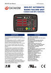
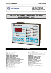
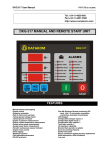
DKG-105 User Manual V-16 DKG-105 AUTOMATIC MAINS FAILURE UNIT FEATURES Automatic engine starting and stopping Gas engine support Automatic mains failure monitoring Automatic load transfer Automatic shutdown on fault condition Test mode available Survives cranking dropouts Provision for energize to stop, preheat & choke outputs Mains phases voltage limits checking Generator phase voltage limits checking Delayed overspeed and underspeed alarm Digitally adjustable low & high mains voltage limits Digitally adjustable low & high generator voltage limits Digitally adjustable underspeed & overspeed limits Digitally adjustable delay for speed alarm Digitally adjustable timers Digital display of mains & generator voltages Digital display of generator frequency Plug-in connection system for easy replacement Low cost Small dimensions Standard panel dimensions, (72x72mm) DKG-105 User Manual V-16 TABLE OF CONTENTS Section 1. PROGRAMMING SUMMARY 2. INSTALLATION 2.1. Introduction to the Control Panel 2.2. Mounting the Unit 2.3. Wiring the Unit 2.4. Inputs and Outputs 2.5. Displays 2.6. Alarms 2.7. Modes of Operation 3. MAINTENANCE 4. TROUBLESHOOTING 5. PROGRAMMING 6. TECHNICAL SPECIFICATIONS 7. DECLARATION OF CONFORMITY 8. CONNECTION DIAGRAM -2- DKG-105 User Manual V-16 1. PROGRAMMING SUMMARY To enter the program mode, first press the OFF button, then the MENU button and hold the two buttons pressed for 4 seconds. The display shows (Pr) when program mode is selected. PGM NUMBER PROGRAM OPTION UNIT FACT SET MIN. VAL. MAX. VAL. P01 Mains Voltage Lower Limit Volt 170 30 250 P02 Mains Voltage Upper Limit Volt 270 100 400 P03 Generator Voltage Lower Limit Volt 170 30 250 P04 Generator Voltage Upper Limit Volt 270 100 400 P05 Frequency Lower Limit Hz. 45 10 60 P06 Frequency Upper Limit Hz. 57 50 100 P07 Frequency Delay Timer Sec. 3 0 15 P08 Number of Start Attempts - 3 1 6 P09 Wait before Start Timer Sec. 3 0 240 P10 Wait between Starts Timer Sec. 10 2 30 P11 Start Timer Sec. 10 2 15 P12 Stop Timer Sec. 0 0 60 P13 Mains Waiting Timer Min. 0.5 0 15 P14 Cooling Timer Min. 1.0 0 15 P15 Mains Contactor Timer Sec. 1 0 15 P16 Generator Contactor Timer Sec. 4 0 240 P17 Relay and Oil Pressure Configuration - 0 0 15 P18 Wait Before Fuel Timer Min. 0 0 240 P19 Emergency Stop/Remote Start - 0 0 1 P20 Max Engine Run Time Limit Hour 0 0 18 P21 Choke Relay Timer Sec. 3.0 0.5 90 P22 Gas Engine Fuel Solenoid Delay Sec. 0.0 0.5 20 -3- DKG-105 User Manual V-16 2. INSTALLATION 2.1 Introduction to the Control Panel The control panel is designed to provide user friendliness for both the installer and the user. Programming is usually unnecessary, as the factory settings have been carefully selected to fit most applications. However programmable parameters allow the complete control over the generating set. Programmed parameters are stored in a Non Volatile Memory and thus all information is retained even in the event of complete loss of power. 2.2 Mounting the Unit The unit is designed for panel mounting. The user should not be able to access parts of the unit other than the front panel. Mount the unit on a flat, vertical surface. The unit fits into a standard panel meter opening of 68x68 millimeters. Before mounting, remove the steel spring and the plug connectors from the unit, and then pass the unit through the mounting opening. The unit will be maintained in its position by the steel spring. 2.3 Wiring the Unit WARNING: THE UNIT IS NOT FUSED. Use external fuses for Mains phases: R, S, T, Generator phase: G, Battery positive: BAT(+). Install the fuses as nearly as possible to the unit in a place easily accessible for the user. The fuse rating should be 6 Amps. WARNING: ELECTRICITY CAN KILL ALWAYS disconnect the power BEFORE connecting the unit.The fuse rating should be 6 Amps. 1) ALWAYS remove the plug connectors when inserting wires with a screwdriver. 2) ALWAYS refer to the National Wiring Regulations when conducting installation. 3) An appropriate and readily accessible set of disconnection devices (e.g. automatic fuses) MUST be provided as part of the installation. 4) The disconnection device must NOT be fitted in a flexible cord. 5) The building mains supply MUST incorporate appropriate short-circuit backup protection (e.g. a fuse or circuit breaker) of High Breaking Capacity (HBC, at least 1500A). Use cables of adequate current carrying capacity 2 (at least 0.75mm ) and temperature range. -4- DKG-105 User Manual V-16 2.4 Inputs and Outputs 1- N: Neutral terminal for both the mains and generator phases. 2- G: Connect one of the generator phases to this input. The generator phase voltage upper and lower limits are programmable. 3- GENERATOR CONTACTOR: This output provides energy to the generator contactor. If the generator phase voltage is outside of the programmed limits, the generator contactor will be de-energized. In order to provide extra security, normally closed contact of the mains contactor should be serially connected to this output. Relay contact rating is 16A/250V-AC 4/5/6- T/S/R: Connect the mains phases to these inputs. The mains voltages upper and lower limits are programmable. 7- MAINS CONTACTOR: This output provides energy to the mains contactor. If the voltage of at least one of the mains voltages is outside of the programmed limits, the mains contactor will be de-energized. In order to provide extra security, normally closed contact of the generator contactor should be serially connected to this output. Relay contact rating is 16A/250V-AC 8- HIGH TEMPERATURE SWITCH: Connect the high temperature switch to this input. This switch shall be negative closing switch type. 9- LOW OIL PRESSURE / LOW OIL LEVEL: Connect the low oil pressure (or low oil level) switch to this input. The switch should be negative closing in case of loss of oil pressure (or low oil level). This input must be properly connected for the correct operation of the unit. If oil pressure is provided, the generator will not start and the oil pressure alarm indicator will flash. However, if the oil pressure is removed, the unit will resume normal operation. 10- FUEL OUTPUT: This output is used on engines equipped with a fuel solenoid. The unit activates this output before starting the engine and deactivates it to stop it. By programming, this relay can also control 'Activate to Stop’ type of engines. Relay contact rating is 10A/28V-DC. 11- CRANK OUTPUT: Engine crank output. Relay automatically turns off when the alternator voltage reaches 100 volts or the alternator frequency reaches 10Hz. Relay contact rating is 10A/28V-DC. 12- AUXILIARY RELAY OUTPUT: This relay fulfills 5 different functions following programming. Relay contact rating is 10A/28V-DC. 1) ALARM RELAY: If an alarm occurs, the relay will be activated. It will be deactivated when any key is pressed. 2) STOP RELAY: The relay will operate during programmed period in order to stop the engine (Activate to Stop) 3) PREHEAT RELAY: The relay will operate the programmed delay before the cranking of the engine. It will be deactivated during cranking and reactivated during the rest period between cranks. It will be deactivated when the engine runs. 4) CHOKE RELAY: The relay will operate the programmed delay before the cranking of the engine. It will be deactivated when the engine runs. 5) GAS ENGINE FUEL SOLENOID: The relay will operate after the crank output has been activated. The delay is programmed with program parameter P_22. 13/14- BAT(-)/BAT(+): The positive (+) and negative (-) terminals of the DC Supply shall be connected to these terminals. Be careful for the polarization, in case of polarity error the unit will not operate. The unit operates on both 12V and 24V battery systems. -5- DKG-105 User Manual V-16 2.5 Displays DIGITAL DISPLAY: This display shows: - (R) phase voltage, when mains are on - Alternator frequency, if the generator is on - Program values in program mode Below values can be read in sequence by pushing the MENU key in AUTO or TEST modes: - (R) phase voltage - (S) phase voltage - (T) phase voltage - (G) phase voltage - (G) phase frequency (engine RPM) GENERATOR: (yellow) it flashes if the (G) phase voltage is within programmed limits. It turns on when the generator contactor is activated. MAINS: (green) it flashes when all (R-S-T) phase voltages are within the programmed limits. It turns on when the mains contactor is activated. TEST/AUTO: It turns on when the related operation mode is selected. 2.6 Alarms Alarms indicate an abnormal situation in the generating set and cause the engine to stop immediately. If an alarm occurs, the related LED will turn on and the alarm relay will be activated. If any key is pressed, the alarm relay will be deactivated. Alarm LEDs will stay on and disable the operation of the generating set even if the alarm source is removed. In order to reset the alarm condition, first choose OFF mode then resume to the previous mode of operation. HIGH TEMPERATURE ALARM: It is on when a signal comes from the high temperature input. OIL ALARM: It is on when a signal comes from the oil pressure/oil level input. This alarm will be controlled 8 seconds after the engine is running. If oil pressure is provided when the unit attempts to start the engine, the oil alarm indicator will flash and the unit will wait until oil pressure disappears. FREQUENCY/VOLTAGE ALARM: It is on when the alternator frequency is out of the programmed limits for a longer period than the programmed timer. It flashes when the alternator voltage is out of the programmed limits. Alternator frequency and voltage will be controlled 4 seconds after the generator contactor is on. FAIL TO START: It is on if the engine cannot start to run after the programmed number of start attempts. This alarm will be erased when the mains are on in order to keep the engine ready for the next mains failure. -6- DKG-105 User Manual V-16 2.7 Modes of Operation The modes of operation are selected by pressing the front panel keys. OFF: In this mode, the mains contactor will be energized if mains phase voltages are within the programmed limits. The engine will be stopped. AUTO: It is used for generator and mains automatic transfer. If at least one of the mains phase voltages is outside limits, the mains contactor will be deactivated. The diesel will be started for programmed times after the wait period. When the engine runs, the crank relay will be immediately deactivated. After the G phase voltage is within the limits, the unit will wait for the generator contactor period and the generator contactor will be energized. When all the mains phase voltages are within the limits, the engine will continue to run for the mains waiting period. At the end of this period the generator contactor is deactivated and mains contactor will be energized. If a cooling period is given, the generator will continue to run during cooling period. At the end of the period, the fuel solenoid will be de-energized and the diesel will stop. The unit will be ready for the next mains failure. TEST: It is used to test the generator when the mains are on, or keep the generator waiting in the emergency backup mode. The operation of the generator is similar to the AUTO mode, but the mains contactor will not be deactivated if the mains are not off. If the mains are off, mains contactor will be deactivated and the generator contactor will be activated. When the mains are on again, a changeover to the mains will be made, but the engine is kept running. In order to stop the engine, push the OFF button. DISPLAY TEST: It is used to test the functionality of the displays. This mode is selected when OFF and TEST buttons are pressed together and deselected when no button is pressed. PROGRAM: It is used to program the timers and operational limits. 3. MAINTENANCE DO NOT OPEN THE UNIT ! There are NO serviceable parts inside the unit. Wipe the unit, if necessary with a soft damp cloth. Do not use chemical agents -7- DKG-105 User Manual V-16 4. TROUBLESHOOTING The genset starts to operate while AC mains are OK: AC mains voltages may be outside programmed limits. Read AC voltages by pressing the MENU button. Upper and lower limits of the mains voltages may be too tight. Get in the PROGRAM mode and check for the AC voltage upper and lower limits. If necessary, widen the limits. The genset continues to operate after AC mains are reestablished: Widen the AC voltage limits. The hysteresis value for the AC voltages is 10 volts. When the AC mains fail, the lower limit is raised and the upper limit is reduced by the hysteresis value to prevent a new load transfer after the load is transferred to the mains. AC voltages displayed on the unit are not correct: The error margin of the unit is +/- 5 volts. If there are faulty measurements only when the engine is running, there may be a faulty charging alternator or voltage regulator on the engine. Disconnect the charging alternator connection and check if the error is removed. When the AC mains fails the unit energizes the fuel solenoid, but does not start, also OIL PRESSURE ALARM led flashes: The unit is not supplied with battery (-) voltage at the oil pressure input. -Oil pressure switch not connected. -Oil pressure switch connection wire cut. -Oil pressure switch faulty. -Oil pressure switch closes too lately. If oil pressure falls, the unit will start. Optionally oil pressure switch may be replaced. The engine does not run after the first start attempt, then the unit does not start again and the OIL PRESSURE ALARM led flashes: -The oil pressure switch closes very lately. As the unit senses an oil pressure, it does not start. When oil pressure falls the unit will start. Optionally the oil pressure switch may be replaced. When the AC mains fails, the engine starts to run but the unit gives FAIL TO START alarm and then the engine stops: -The generator phase voltage is not connected to the unit. Measure the AC voltage between terminals (G) and (Neutral) at the rear of the unit while engine is running. The fuse protecting the generator phase may be failed. A misconnection may be occurred. If everything is OK, turn all the fuses off, and then turn all the fuses on, starting from the DC supply fuse. Then test the unit again. The unit is late to remove engine cranking: -The alternator voltage rises lately. Also the generator remanant voltage is below 30 volts. The unit removes starting with the generator frequency, and needs at least 30 volts to measure the frequency. If this situation is to be avoided, the only solution is to add an auxiliary relay. The coil of the relay will be between BATTERY (-) and charging alternator LAMP terminal. The normally closed contact of the relay will be connected serially to the unit's START output. So the starting will also be removed when the CHARGE LAMP turns off. -8- DKG-105 User Manual V-16 The unit is inoperative: -Measure the DC-supply voltage between (+) and (-) terminals at the rear of the unit. If OK, turn all the fuses off, then turn all the fuses on, starting from the DC supply fuse. Then try the unit again. 5. PROGRAMMING The programming mode is used to program the timers, operational limits and the configuration of the unit. To enter the program mode, first press the OFF button, then the MENU button and hold the two buttons pressed for 4 seconds. The display shows (Pr) when program mode is selected. Each time the MENU key is pushed, the next program number will display and whenever it is released the program value will be shown. For example if you push MENU key and keep pushing, you will see (P01) on the display. When you release MENU key you will see P01’s value that you can increase or decrease by using TEST (-) and AUTO (+) keys. If you push again the MENU key, you will see (P02) on the display and when you release it you will see P02 value. You can continue so until P20. After P20 you will turn back to P01. Programmed values are stored in a Non Volatile Memory, which is not affected by energy failures. To exit programming press the OFF button. P01 = MAINS VOLTAGE LOWER LIMIT: If one of the mains phases goes under this limit, it means that the mains are off and it starts the transfer to the generator in AUTO or TEST modes. P02 = MAINS VOLTAGE UPPER LIMIT: If one of the mains phases goes over this limit, it means that the mains are off and it starts the transfer to the generator in AUTO or TEST modes. P03 = GENERATOR VOLTAGE LOWER LIMIT: If the generator phase voltage goes under this limit when feeding the load, this will mean a generator voltage failure and the engine will stop. P04 = GENERATOR VOLTAGE UPPER LIMIT: If the generator phase voltage goes over this limit when feeding the load, this will mean a generator voltage failure and the engine will stop. P05 = FREQUENCY LOWER LIMIT: If (G) phase frequency goes under this value for a period longer than frequency delay timer, while the generator is feeding the load, it causes the frequency alarm (underspeed) and the engine will stop immediately. This limit is not controlled in the first 4 seconds after the generator contactor has been energized. P06 = FREQUENCY UPPER LIMIT: If (G) phase frequency goes over this value for a period longer than frequency delay timer, while the generator is feeding the load, it causes the frequency alarm (overspeed) and the engine will stop immediately. This limit is not controlled in the first 4 seconds after the generator contactor has been energized. P07 = FREQUENCY DELAY TIMER: If (G) phase frequency goes out of the programmed values for a period longer than frequency delay timer, while the engine is running, it causes the frequency alarm and the generator will stop immediately. P08 = NUMBER OF START CYCLES: The generator start attempts cannot exceed this number. P09 =WAIT BEFORE START TIMER: The waiting period before start. (Also called preheat timer) P10 =WAIT BETWEEN STARTS TIMER: The waiting period between starts. P11 =START TIMER: The engine starting period cannot exceed this number. P12 =STOP TIMER: It adjusts the stop solenoid energizing period in order to stop the generator. P13 =MAINS WAITING TIMER: This is the time between the mains voltages are within the limits and the load transferred from the generator to the mains. -9- DKG-105 User Manual V-16 P14 =COOLING TIMER: This is the period that the engine runs with no load, after the load changeover to the mains. P15 =MAINS CONTACTOR TIMER: This is the period after the generator contactor has been deactivated and before the mains contactor has been activated. P16 =GENERATOR CONTACTOR TIMER: This is the period after the mains contactor has been deactivated and before the generator contactor has been activated. P17 =RELAY AND OIL PRESSURE CONFIGURATION: FUEL and AUXILIARY relay configuration, as well as the oil switch input type: P17 VAL AUX RELAY FUNCTION FUEL RELAY FUNCTION OIL INPUT TYPE 00 Alarm Activate before Start Oil Pressure Switch 01 Fuel (Activate to Stop) Activate before Start Oil Pressure Switch 02 Preheat Activate before Start Oil Pressure Switch 03 Choke Activate before Start Oil Pressure Switch 04 Alarm Activate before Start Oil Level Switch 05 Fuel (Activate to Stop) Activate before Start Oil Level Switch 06 Preheat Activate before Start Oil Level Switch 07 Choke Activate before Start Oil Level Switch 08 Alarm Activate to Stop Oil Pressure Switch 09 Fuel (Activate to Stop) Activate to Stop Oil Pressure Switch 10 Preheat Activate to Stop Oil Pressure Switch 11 Choke Activate to Stop Oil Pressure Switch 12 Alarm Activate to Stop Oil Level Switch 13 Fuel (Activate to Stop) Activate to Stop Oil Level Switch 14 Preheat Activate to Stop Oil Level Switch 15 Choke Activate to Stop Oil Level Switch P18 =WAIT BEFORE FUEL TIMER: The waiting period after the mains failure and before the fuel output active. (used for UPS backed up gensets) P19 =EMERGENCY STOP/REMOTE START SELECTION: (Valid only if an extra input provided) If this parameter is programmed to 0, then the extra input acts as a REMOTE START input, so the input is not latched and no alarm signal generated. If this parameter is programmed to 1, then the extra input acts as an EMERGENCY STOP input, so the fault signal is latched and alarm signal generated. P20 = MAX. ENGINE RUN TIME LIMIT: This is the maximum time limit for the engine to run continuously. When used together with the WAIT BEFORE FUEL TIMER (P18), this will provide the genset with an intermittent operation. P21 = CHOKE TIMER: If the AUXILIARY RELAY is defined as choke output, this relay will operate together with the start relay and release at the expiration of this timer. By programming this timer to adequate values the choke may be released before or after the engine run. P22 = GAS ENGINE FUEL SOLENOID: If this parameter is set to 0.0 (factory default), then the AUXILIARY RELAY will operate as implied by P21. Otherwise the relay will operate after the crank output delayed by this timer. It will release when the engine is to be stopped. - 10 - DKG-105 User Manual V-16 6. TECHNICAL SPECIFICATIONS Mains voltage: 277VAC (Ph-N) Mains frequency: 50/60Hz. Power System Type: TN or TT. Alternator voltage: 277VAC (Ph-N) Alternator frequency: 0-100Hz. Measurement Category: CAT II DC Supply Range: 9 to 33 VDC. 4.0 – 33 VDC while cranking Current consumption: 60 mADC typical (AUTO mode, mains OK) 200 mADC max. (Relay outputs open) Total DC Current Output Rating: 10ADC. Total AC Current Output Rating: 10AAC. Current Rating for each Output Terminal: 10ARMS. Operating temperature range: -20C (-4F) to 70 C (158F). Storage temperature range: -30C (-22F) to 80 C (176F). Maximum humidity: 95% non-condensing. Dimensions: 72 x 72 x 76mm (WxHxD) Mounting opening dimensions: 68 x 68mm minimum. Weight: 240 g (approx.) Accuracy: Phase voltages: 2% + 1v Generator frequency: +/- 0.5 Hz Case Material: Flame Retardant High Temperature ABS (UL94-V0, 110C) Stresses exceeding above limits may result to a degradation of the unit’s protection level. 7. DECLARATION OF CONFORMITY The unit conforms to the EU directives -2006/95/EC (low voltage) -2004/108/EC (electro-magnetic compatibility) Norms of reference: EN 61010 (safety requirements) EN 61326 (EMC requirements) The CE mark indicates that this product complies with the European requirements for safety, health environmental and customer protection. - 11 - DKG-105 User Manual V-16 8. CONNECTION DIAGRAM DATAKOM Electronics Ltd. Tel: +90-216-466 84 60 Fax: +90-216-364 65 65 e-mail: [email protected] http: www.datakom.com.tr - 12 -