1
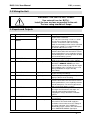
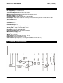
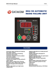
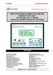
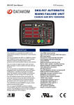
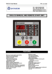
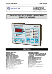
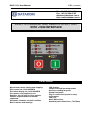
DKG-114-J User Manual
V-01 (15.04.2008)
Tel: +90-216-466 84 60
Fax: +90-216 364 65 65
[email protected]
http://www.datakom.com.tr
DKG-114-J MANUAL AND REMOTE START UNIT
WITH J1939 INTERFACE
FEATURES
Manual and remote starting and stopping
ECU control via J1939 CANBUS
ECU alarm display via J1939 CANBUS
Zero power consumption at rest
Replaces the CIU unit in Volvo engines
Various engine brands and models
supported
Automatic shutdown on fault condition
Built in alarms and warnings
LED displays
Jumper selected operating modes
Survives cranking dropouts
Sealed front panel
Plug-in connection system for easy
replacement
Low cost,
Small dimensions,
Standard panel dimensions, (72x72mm)
DKG-114-J User Manual
V-01 (15.04.2008)
TABLE OF CONTENTS
Section
1. DESCRIPTION
2. INSTALLATION
2.1. Introduction to the Control Panel
2.2. Mounting the Unit
2.3. Wiring the Unit
2.4. Inputs and outputs
3. DISPLAYS
4. ALARMS
5. MODES OF OPERATION
6. J1939 ENGINE MONITORING AND CONTROL PORT
7. JUMPER SELECTOR SWITCHES
8. MAINTENANCE
9. TROUBLESHOOTING
10. DECLARATION OF CONFORMITY
11. TECHNICAL SPECIFICATIONS
12. CONNECTION DIAGRAM
-2-
DKG-114-J User Manual
V-01 (15.04.2008)
1. DESCRIPTION
The DKG-114-J is a low cost engine control unit designed to start and stop electronic engines both
manually and remotely. The manual control is made using the pushbuttons on the front panel. The remote
control is made via the REMOTE START input signal.
The unit connects to ECU controlled electronic engines through its standard J1939 CANBUS port
providing engine control and protection without extra senders. It has the ability of engine starting and
stopping with J1939 messages. The ECU alarms are displayed with appropriate leds.
The message starting feature allows removal of the CIU unit in message started engines.
In the STOP position, the DC supply is removed from the module, thus zero power consumption
is achieved.
The unit powers up when the RUN button is pressed or BAT + is applied to the REMOTE START
input. This will also energize the fuel solenoid relay. The engine is automatically started 3 times until
operation.
Once the engine is running, it monitors the ECU alarms. If a fault condition occurs, the unit shuts down
the engine automatically and indicates the failure source with the corresponding red led lamp.
If the STOP button is pressed or the REMOTE START signal removed, the engine will be stopped.
The unit offers jumper selectable operating parameters, which lets it to be used with various engine brands
and models.
The unit fits into a standard 72x72mm panel meter opening and offers a very cost effective and space
saving solution for the electronic engine control. Thanks to the completely sealed structure, IP65 protection
degree is achieved from the front panel.
The unit works on both 12 Volt and 24 Volt gensets.
2. INSTALLATION
2.1 Introduction to the Control Panel
The control panel is designed to provide user friendliness for both the installer and the user.
Jumper selectors allow the complete control over the generating set or engine.
2.2 Mounting the Unit
The unit is designed for panel mounting. The user should not be able to access parts of the unit other than
the front panel.
Mount the unit on a flat, vertical surface. The unit fits into a standard panel meter opening of 68x68 millimeters.
Before mounting, remove the mounting brackets and connectors from the unit, then pass the unit through the
mounting opening. The unit will be maintained in its position by the mounting brackets.
Please use a twisted pair of cable or a dedicated 120 ohms coaxial cable for the CANBUS connection. The
shield of the cable should be grounded at one end only.
The charge alternator connection terminal provides also the excitation current, thus it is not necessary
to use an external charge lamp.
-3-
DKG-114-J User Manual
V-01 (15.04.2008)
2.3 Wiring the Unit
WARNING: THE UNIT IS NOT FUSED.
Use external fuse for: BAT(+).
Install the fuse as close as possible to the unit.
The fuse rating should be 6 Amps.
2.4 Inputs and Outputs
Term Function
1
J1939
2
J1939
+
-
3
GROUND
4
START RELAY
5
REMOTE START
6
EMERGENCY STOP
7
LAMP TEST
8
BATTERY POSITIVE
9
FUEL RELAY
10
ALARM RELAY
11
CHARGE
Technical data
Description
Digital communication Connect the J1939 port of an electronic
port
engine to these terminals.
The 120 ohm terminating resistors are inside
the unit. Please do not connect external
resistors. If external resistors are already
fitted, the terminating resistor can be cancelled
with jumper control. Use a twisted cable pair
or coaxial cable for best results.
0VDC
The negative (-) terminal of the DC Supply
shall be connected to this terminal. Be careful
for the polarization, in case of polarity error the
unit will not operate. The unit operates on both
12V and 24V battery systems.
Output 10A/28VDC
Engine crank output. Relay automatically turns
off when the engine speed reaches 300rpm.
Digital input
A battery positive connection to this terminal
will initiate a REMOTE START cycle. If the
signal is disconnected, this will stop the engine
after cooldown cycle. If STOP key is pressed
during Cooldown, the engine will stop
immediately.
Digital input
If battery negative is applied to this input, the
engine will stop immediately.
Digital input
If battery negative is applied to this input, all
displays will turn on for checking.
+12 or 24VDC
The positive (+) terminal of the DC Supply
shall be connected to this terminal. Be careful
for the polarization, in case of polarity error the
unit will not operate. The unit may operate on
both 12V and 24V battery systems.
Output 10A/28VDC
The unit activates this output before starting
the engine and deactivates it to stop it. It is
internally connected to terminal 11 for
supplying the charge alternator’s excitation
current.
Output 10A/28VDC
This relay is activated when a fault condition
has occurred.
Input and output
Connect the charge alternator’s D+ terminal to
this terminal. This terminal will supply the
excitation current and measure the voltage of
the charge alternator. If the CANBUS is
disabled by jumper selection, this terminal will
act as ENGINE RUNNING signal input.
-4-
DKG-114-J User Manual
V-01 (15.04.2008)
3. DISPLAYS
POWER: (green) it flashes when the unit is powered on. It turns steadily on when the engine is running.
REMOTE START: (yellow) it turns on when the remote start signal is present.
4. ALARMS
Alarms indicate an abnormal situation in the engine and cause:
- The related alarm led to turn on steadily,
- The engine to stop immediately,
- The Alarm relay output to operate,
- The related alarm source led to flash.
Alarm LEDs will stay on and disable the operation of the engine even if the alarm source is removed. In
order to reset the alarm conditions press the STOP button.
COMMUNICATION LOST: Set if no information has been received during 3 seconds from the ECU of the
electronic engine. This fault condition is only controlled when the fuel is on.
ECU FAIL: Set when an engine fault code is received from the ECU of the electronic engine. The alarm
source will also be indicated by flashing OIL, TEMP and SPEED leds wherever applicable.
OIL: Flashes if a fault code concerning the oil pressure is received from the ECU of the electronic engine.
TEMP: Flashes if a fault code concerning the coolant temperature is received from the ECU of the electronic
engine.
SPEED: Flashes if a fault code concerning the engine rpm is received from the ECU of the electronic engine.
5. MODES OF OPERATION
The modes of operation are selected by pressing the front panel keys.
MANUAL START / REMOTE START: Manual start mode is entered by pressing the front panel RUN key,
remote start mode is entered by applying the battery positive voltage to the REMOTE START terminal.
In both modes, the engine will be started 3 times. When the engine runs, the crank relay will be immediately
deactivated.
MANUAL STOP / REMOTE STOP: Manual stop mode is entered by pressing the front panel STOP key,
remote stop mode is entered by disconnecting the battery positive voltage from the REMOTE START terminal.
When engine stop is requested, a cooldown cycle of 30 seconds will be entered. At the end of the cooldown
cycle the engine will stop. If immediate stop is requested, the STOP key should be pressed again.
If no alarm exists, the unit disconnects from the power source in order to reach zero power consumption. If
alarm exists, the unit will not power off until the front panel STOP key is pressed.
-5-
DKG-114-J User Manual
V-01 (15.04.2008)
6. J1939 ENGINE MONITORING AND CONTROL PORT
The unit offers a special J1939 port in order to communicate with electronic engines controlled by
an ECU (electronic control unit).
The J1939 port consists of 2 terminals which are J1939+ and J1939-. The connection between the
unit and the engine should be made with either a twisted cable pair or a coaxial cable. If a coaxial cable is
used, the external conductor should be grounded at one end only.
The 120 ohms termination resistor is included inside the unit with jumper control. Please do not
connect external resistor. If the terminating resistor is already installed, the internal 120 ohms resistor may
be cancelled by removing JP1.
The J1939 port is activated by inserting the jumper JP2.
If the engine is a message started type like Volvo models insert also jumper JP3.
Please contact DATAKOM for the current list of supported engines.
When the fuel output is active, if no information is received from the ECU during last 3 seconds,
then the unit will give a COMMUNICATION LOST alarm and stop the engine. This feature prevents
uncontrolled engine operation.
Any fault condition received from the ECU of the electronic engine will also cause the engine to be
stopped. If the fault condition is caused by the oil pressure sensor, coolant temperature sensor or engine
speed sensor the related alarm led will also flash.
7. JUMPER SELECTOR SWITCHES
FUNCTION
JUMPERS
Terminating resistor
JP1
CANBUS enable
JP2
Message start
JP3
SETTINGS
ON: 120 ohms Terminating resistor is inserted
OFF: No terminating resistor
ON: CANBUS communication enabled
OFF: CANBUS communication disabled
ON: Message started engine (some Volvo types)
OFF: Crank relay started engine (most common engine type)
8. MAINTENANCE
DO NOT OPEN THE UNIT
There are NO serviceable parts inside the unit.
Wipe the unit, if necessary with a soft damp cloth. Do not use chemical agents
-6-
DKG-114-J User Manual
V-01 (15.04.2008)
9. TROUBLESHOOTING
When the RUN key is pressed the unit gives COMMUNICATION LOST alarm:
- Check that CANBUS J1939 cables are connected properly to the ECU.
- Check the terminating resistor necessity and set jumper JP1 accordingly.
- Check polarity reversal of the cables.
- Connect the ground terminal of the unit to the ground terminal of the ECU.
- Use coaxial cable, ground at one end.
- Check sanity of the ECU.
When the engine is running the unit gives COMMUNICATION LOST alarm:
- Excessive EMI noise:
- Connect the ground terminal of the unit to the ground terminal of the ECU.
- Use coaxial cable, ground at one end.
- Check the terminating resistor necessity and set jumper JP1 accordingly.
10. DECLARATION OF CONFORMITY
The unit conforms to the EU directives
-2006/95/EC (low voltage)
-2004/108/EC (electro-magnetic compatibility)
Norms of reference:
EN 61010 (safety requirements)
EN 61326 (EMC requirements)
The CE mark indicates that this product complies with the European requirements for safety, health
environmental and customer protection.
-7-
DKG-114-J User Manual
V-01 (15.04.2008)
11. TECHNICAL SPECIFICATIONS
DC Supply Range: 9.0 to 30.0 V-DC
Cranking dropouts: survives 0 V for 100ms.
Typical Standby Current: 0 mA-DC in OFF mode.
Maximum Operating Current: 250 mA-DC (Relay outputs open)
DC Relay Outputs: 10 A / 28V-DC
Charge excitation current: 150mA-min @ 10 to 30V-DC
Digital inputs: input voltage 0 - 30 VDC. Internally connected to battery positive via 4700 ohm resistor.
Number of starts: 3
Start duration: 8 sec.
Wait between starts: 10 sec.
Cooldown: 30 sec.
Alarm duration: 1 minute.
Protection delay: 8 sec.
Operating temp.: -20°C (-4°F) to 70 °C (158°F).
Storage temp.: -40°C (-40°F) to 80 °C (176°F).
Humidity: max 95% (non-condensing)
Dimensions: 72 x 72 x 43 mm (WxHxD)
Panel Cut-out Dimensions: 69 x 69 mm minimum.
Measurement category: CAT II
Air category: Pollution degree II
Weight: 180 g (approx.)
Case Material: High Temp. ABS (UL94-V0, 100°C)
IP Protection: front panel:IP65, rear: IP30
Case material: High temperature, self extinguishing ABS (UL94-V0, 100 °C)
12. CONNECTION DIAGRAM
-8-