1
USER MANUAL
TO REDUCE THE RISK OF INJURY USER MUST READ AND UNDERSTAND INSTRUCTION MANUAL
ECO.100/4
Magnetic Drilling Machine
SERIAL NO._______________ DATE OF PURCHASE _____________
1 - Table of Contents
1
2
3
4
4
4
5
6
Table of Contents ……………………………………………………………………………………………………
Safety ……………………………………………………………………………………………………………………..
Before Use ………………………………………………………………………………………………………………
Items Included in Delivery ……………………………………………………………………………………….
The Hole Cutter
Hole Cutter Selection .................................................................................................
Cooling/Lubrication ...................................................................................................
Tool Assembly
Morse Taper Assembly ………………….........…………………………………………………………………
Hole Cutter Assembly ………………….........…………………………………………………………………
Drill Chuck Assembly ……………………………….........…………………………………………………….
Installation of 13mm Chuck by using Adaptor IBK.14 ................................................
Installation of 13mm Chuck directly on the motor unit ............................................
The Magnetic Drilling Machine
The Magnetic Base ....................................................................................................
The Control Panel ......................................................................................................
Electronic Controls ......................................................................................................
4 Speed Gearbox ........................................................................................................
Drilling ........................................................................................................................
Tapping ......................................................................................................................
Maintenance ................................…………………………………………………………………………..
Spareparts & Exploded View.........…………………………………………………………………….......
page
page
page
page
1
2
3
4
page 5
page 6
page
page
page
page
page
6
6
7
7
7
page 7
page 8
page 8
page 8
page 10
page 10
page 11
page 12
Read these directions and safety instructions
completely and attentively and carefully follow
these recommendations.
All safety measures must be observed at all times
when using magnetic drilling machines. Improper
use and carelessness increase the risk of accidents.
This is for your own safety.
Should you have any doubts about the use of this machine, please contact your supplier.
2
2 - Safety
1. During any work on non-horizontal components, the machine must always be secured with the
supplied safety chain.
2. The magnetic drilling machine may only be used on a flat and clean foundation.
3. If the machine or the lead show signs of damage, the magnetic drilling machine must be switched
off immediately.
4. Wearing safety glasses, hearing protection and protective clothing is necessary.
5. Do not wear any loose clothing or jewellery that may get entangled in the moving parts of the
magnetic drilling machine.
6. Use only accessories or parts that are recommended by Euroboor.
7. During drill operations, the hole cutter must be cooled and lubricated with good quality cutting or
lubrication oil.
8. The motor must be switched off when tightening the machine with the safety chain.
9. When changing a hole cutter, the magnetic drilling machine must be disconnected from power
supply.
10. Clean the area around the machine regularly. Keep the bottom of the magnet and keep it clean and
dry.
11. Regularly inspect whether all screws, nuts and bolts are tight.
12. Remove the burr or slug from the hole cutter after each hole. Caution, the part may be hot!
13. Before using the machine make sure it is connected to the correct voltage and that all grips and
parts are tightly attached.
14. When using the drill on non-horizontal surfaces, you must use a drilling compound or cutting paste.
15. Do not use oil because the oil can drip into the motor unit.
When using this machine, you MUST wear ear and eye protection.
Euroboor has included these articles as standard accessories for your own
safety. Do NOT touch the drill when it is running. Always follow the
recommendations for personal protection when using this tool.
3
Before use
Euroboor magnet drilling machines are specially designed for drilling holes is steel, possibly expanded by
the possibility of tapping/reaming/countersinking (depending on model). Euroboor magnetic drilling
machines may not be adapted and/or used for applications other than those they were designed for,
including driving other machines.
Make sure that you can oversee the entire work areas from where you are operating this machine. Use
barriers to keep others away. Do not use the machine in places subject to hazard of explosion- electrical
tools produce sparks which may ignite flammable materials or gasses. To prevent electrical shocks, do not
use the machine in moist or wet conditions or environments. Always operate this tool using both hands.
Make sure the work piece is always clamped down safety.
This magnetic drilling machine is equipped with a lead and plug approved for the country or region it is to
be used in. The yellow-green wire in the lead is the earth wire. Never connect this to a pole under voltage.
All Euroboor magnetic drilling machines are manufactured to use with AC current and not suitable to work
on DC current. Make sure the magnetic drilling machine is connected to a stable power supply. Euroboor
do not recommend the use of a generator or other mobile power supply for power supply. Euroboor does
not recommend the use of extension cables. If there is no other way, use good quality cables and keep
extension cables as short as possible. Be aware that long power leads can cause less current.
3 - Items Included in Delivery
Magnetic Drilling Machine
Carrying Case
Drill Chuck 13mm
Tap Collets M10-M12-M14-M16
Allen Key 2.5
Allen Key 4
Allen Key 5
Allen Key 6
Wrench 8
YES
YES
NO
NO
YES
YES
YES
YES
YES
Pilot Pin
Morse Taper
Morse Taper Ejector Pin
Manual
Safety Chain
Drilling Oil
Safety Ear Protection
Safety Glasses
Safety Gloves
NO
YES
YES
YES
YES
YES
YES
YES
YES
4
4 - The Hole Cutter
Hole Cutter selection
There are many different types of steel. It is not possible to drill all these types of steel with 1 type of
cutter. Euroboor recommended the following :
Euroboor+ HSS Series
For drilling holes in general 37/52 steel and aluminium
HCS
12 mm - 130 mm
Hole cutters with cutting depth 30 mm
increasing by 1 mm
HCL
12 mm - 130 mm
Hole cutters with cutting depth 55 mm
increasing by 1 mm
HCY
20 mm - 50 mm
Hole cutters with cutting depth 75 mm
increasing by 1 mm
HCX
20 mm - 50 mm
Hole cutters with cutting depth 100 mm increasing by 1 mm
Also available in inch sizes:
HCS
7/16” - 5”
HCL
7/16” - 5”
HCY
3/4” - 2 1/16”
HCX
3/4” - 2 1/16”
Hole cutters with cutting depth 30 mm
Hole cutters with cutting depth 55 mm
Hole cutters with cutting depth 75 mm
Hole cutters with cutting depth 100 mm
increasing by 1/16”
increasing by 1/16”
increasing by 1/16”
increasing by 1/16”
Euroboor Cobalt Series For processing steel, stainless steel and other high-quality steel alloy types
IBS
12 mm - 130 mm
Hole cutters with cutting depth 30 mm
increasing by 1 mm
IBL
13 mm - 130 mm
Hole cutters with cutting depth 55 mm
increasing by 1 mm
Euroboor TCT Series
Tungsten Carbide Tipped. Cutters with hard metal teeth
HMS
14 mm - 50 mm
Hole cutters with cutting depth 35 mm
increasing by 1 mm
HML
14 mm - 130 mm
Hole cutters with cutting depth 50 mm
increasing by 1 mm
Euroboor TRC Series
With hard metal teeth, For drilling holes in rails
TRCS.190
19 mm
Hole cutter with cutting depth 35 mm
TRCS.300
30 mm
Hole cutter with cutting depth 35 mm
TRCS.330
33 mm
Hole cutter with cutting depth 35 mm
NOTE :
Hole cutters 12mm - 60mm have a 19,05 mm Weldon shank
Hole cutters 61mm - 130mm have a 31,75 mm Weldon shank
5
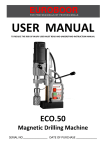
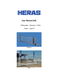
Cooling/Lubrication
1
2
Holes for cooling and lubrication oil
Fixing screws of Morse Conus
Euroboor recommends the use of cooling and lubrication agents. Not only do these
assist in drilling but they will also lengthen the lifespan of your tools. One of the
advantages of the use of hole cutters is that cooling and lubrication agent scan be
supplied from the inside, so that the agents end up in the right place.
All magnetic drilling machines from Euroboor can be equipped with a automatic
cooling system which provides a guaranteed supply of the cooling and lubrication
agents from the inside. If your machine is not be equipped with an automatic coolant
system it will still be possible to cool from the inside.
Use the holes in the morse conus (number 1 in picture) for this purpose by squirting
the cooling and lubrication agent through them and fill the morse conus.
NOTE :
For vertical or upside-down processing, Euroboor recommends the use of a drilling
compound or paste like IBP50/2.
4 - Tool Assembly
Morse Taper Assembly
Mount the Morse Taper into your machine by push it firm into the shaft ectending from the motorunit.
Beware that the tip on top of the Morse Conus is in line with the shaft. To take the Morse Conus out use
the Ejector Pin to force it out.
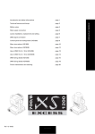
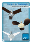
Hole Cutter Assembly
1 : Pilot Pin
2 : Center hole in shank of Hole Cutter
3 : Shank of Hole Cutter
4 : Groove or flatted surface for oil pass
5 : Flat surface for fixing Hole Cutter
Clean the inner wall and the shaft of the Hole Cutter to ensure proper oil supply.
First insert the Pilot Pin into the center hole of the Shank. After that you can slide
the Hole Cutter assembly into the spindle or morse conus of your Magnetic Drilling
Machine. After sliding the Hole Cutter Assembly into the morse conus, make sure
the two flat surfaces (number 5 in picture) are located exactly in front of the two
fixing screws of your spindle (see number 2 in picture of cooling/lubrication. Tighten
them both subsequently with the included 5mm Allen Key.
6
Drill Chuck Assembly
The option of making our machines suitable for the use of standard spiral drills and other tools by using a
cylindrical shaft is an important characteristic of Euroboor magnetic drilling machines. Please see the
technical data for maximum capacity.
Installation of 13mm Chuck by using adapter IBK.14
The IBK.14 is a adaptor from 1/2"x20 UNF to 3/4" Weldon.
Attach a Drill Chuck (like Euroboor IBK.13) with internal 1/2"x20 UNF on the IBK.14 adaptor.
To attach the assembly into your Spindle, follow the instructions (with exception of the Pilot Pin) for
installation of a Hole Cutter. Adaptor IBK.14 can be used on most machines in our program.
Installation of 13mm Chuck directly on the motor unit
For the ECO.80 and ECO.100/4 magnetic drilling machines it is possible to install a drill Chuck directly to
the shaft extending from the motor unit. Attach to the drill chuck with article number IBK.13-B16 a adaptor
with article number B16-MC3. This way the drill chuck can be mounted as a Morse Conus in your machine.
4 - The Magnetic Drilling Machine
The Magnetic base
Material of minimum 10mm thickness is required for the magnet to work the best.
The attachment force generated by the magnet depends on various factors.
- Thickness of the material the magnet is placed on
- Paint or coating of the material the magnet is placed on.
- Metal chips, oil or other dirt under the magnet.
If the LED indicator lights up GREEN, the magnet is generating sufficient attachment force. If the LED
indicator lights up RED, the magnet may not generating sufficient attachment force.
We would like to point out that this is only an indication and not a certainly that the magnet will not
release from the material. Euroboor accepts no liability ensuring from the magnet indicator not
functioning or functioning poorly.
Make sure that the magnet attaches tightly to the work piece before turning on the motor unit of the
magnetic drilling machine. Euroboor magnets have 2 coils; make sure that both coils are in contact with
the material. Do not connect any other machines to the electrical outlet the magnetic drilling machine is
plugged into, as it may result in the loss of magnetic force. Always use the safety chain included. Drilling
above your head is extremely dangerous and is not recommended. For the use of magnetic drilling
machines on pipes, not-flat or non-magnetic materials, we refer to our brochure or our website
www.euroboor.com where several vacuum tightening systems and pipe clamping systems are mentioned.
7
The Control Panel
The control panel on your magnetic drilling machine is designed for maximum operating facility and safety.
1 - The Magnet Switch:
This switch is used to switch the main power
and also the magnet On and Off. This switch is
included on every Euroboor magnetic drilling
machine
2 - The On/Off Switch:
This switch is used to switch the motor unit
On and Off and is included on every Euroboor
Magnetic Drilling Machine
3 - The Fuse holder with Fuse:
This Fuse holder is included on every Euroboor
Magnetic Drilling Machine and holds the fuse
type : 5x20, F2A.
4 - The Magnet LED Indicator:
This LED indicator shows the generated magnetic force.
5 - The L/R Switch:
This switch controls the direction of the motorunit.
The Electronic Controls
On the side of the motorunit are the variable
electronic control wheels. The blue wheel regulate the
rotation speed and the red wheel regulate the torque
power of the motorunit.
When drilling with big diameter cutters or deep holes
start drilling with the torque wheel in a low position to
prevent cutter damage. Increase the power setting a
bit when the machine stops too fast. When the
machine stops cause of torque overload, press the 0
and then the I button of the On/Off switch to start
drilling again.
All-time electronic Temperature protection :
The ECO.100/4 is equipped with a all-time electronic temperature protection. If the temperature of the motorunit
runs upto 70 Degree Celsius the motorunit will stop. After a few minutes it can be started again and we recommend
to let the motor run unloaded with the electronic speed adjustment set on 100% to let the motorunit cool down.
8
4-speed Manual Gearbox
The ECO.100/4 is equipped with a 4-speed gearbox. The two gear switches makes it possible to choose 4 manual
speeds. Also does the ECO.100/4 have a electronic speed adjustment so every wanted speed can be selected.
Important is that the closest mechanical gear is selected first and after that the speed can be decreased by the
electronic adjustment. Therefore, always try to keep the electronic speed wheel above 50% to prevent the armature
to build up heat due low running speed.
600rpm:
left switch up, right switch down
For twist drills and hole cutters till 25mm
370rpm:
left switch up, right switch up
For hole cutters 25-50mm
175rpm:
left switch down, right switch down
For hole cutters 50-75mm
110rpm:
left switch down, right switch up
For hole cutters 75-100mm and tapping.
("left" and "right" is seen from front of motorunit)
Note that the mentioned cutter sizes is only a indication. Depending on variables as the condition of the used cutter,
hardness of material or if oil is used the best drilling speed can be different as mentioned above.
To select other gear, turn off motorunit and main power. Push the black switch on the side of the gearbox and slide
to other position. A slight turn of the output shaft by hand while sliding the black switch to the other position can be
necessary to line up the gears inside. Proof that the gear is locked if the black switch comes back to front.
9
Drilling
Now that you have read the explanatory information and safety recommendations above, you are ready to
actually start drilling. Follow these 10 steps for best drilling result :
1
Use the tip of the pilot pin to determine the center of the hole to be drilled.
2
Turn the magnet on and verify that the drill is in the right position and that the machine is
pushed tight against the work piece.`
3
If your machine is equipped with a auto coolant system, put open the valve to release the oil.
If your machine does not have a auto coolant system, fill the holes of the spindle with oil.
4
Turn the motor on at the highest setting and allow it to run at full speed.
5
Turn the arms to start drilling. Apply only a slight pressure when the hole cutter touch the
metal. Do not push the hole cutter with force into the metal.
6
Apply a regular pressure while drilling. The drilling performance does not improve by putting
more pressure on the tool. Too much pressure will overload the motor and your hole cutter
will be worn sooner. Let the cutter do the job and give it time to cut the metal !!!
7
Adjust the oil supply when necessary, if your drill does not have a auto coolant system, stop
drilling regularly, refill the holes of the spindle and continue drilling.
8
Apply less pressure when the drill cuts through the material.
9
Turn the arms to put the motor in highest position and turn off the motor unit.
10
Remove the burr, metal chips and clean the cutter and surface without getting injuries.
Caution : The metal piece drilled out can be sharp and very hot!!
Tapping ECO.100/4
Drill the hole on the recommended size of the tap. Do not turn the magnet off to keep the machine on its position.
Take the cutter out and use a tap collet (Euroboor TCM series) to fix the tap to the machine. These TCM adapters
exist in several DIN and ISO norms and are based on the shaft diameter of the tap that is used. Use the low gear and
low rpm for tapping. Stop the machine manually before the tap is completely through the hole. Select the Reverse
(Left) and let the tap run back slowly but also support the run back by turning back the handles. Do not let your tap
push back the motorunit by itself! If your tap have to make the whole way through the material, then remove the
tap out of the collet when the hole is completely tapped.
For quick change of taps Euroboor have also special tapholders like the GSW.333 with a insert for every tap size and
the GSW830 with a variable clamp system. See www.euroboor.com for more details about these tapholders.
10
5 - Maintenance
Just as every magnetic drilling machine with moving parts, your Euroboor magnetic drilling machine also
needs regular maintenance service. A few recommendations follow :
-
Clean all dirt, dust, metal chips and burrs of your magnetic drilling machine
-
Regularly check the carbon brushes for wear
-
Replace any defective parts immediately. This prevents properly function parts from being damaged.
-
Adjust your guide regularly and make sure it is clean and greased. This prevents any movement from
being created and the spindle, triangular guide (steady) and guide parts from excessive wear or
damage. The guide can be adjusted by loosening the setting nut (#7 on spare part drawing) with
included wrench 8, tightening the setting screws (#5 on spare part drawing) with included Allen key
2.5 and tightening the setting nut (#7) again with included wrench 8. The adjustment is done well
when the motor unit can be turned to every possible position without falling down by its own weight.
-
Check the grease in the gearbox regularly and replace it if necessary. We recommend you to store
your machine on its side regularly so that the gear box grease can run back to where the gears are.
This is very important when you have used your machine non-horizontal or upside down.
Repair, modification and inspection of Euroboor Magnetic drilling machines must be done by a
Euroboor authorized dealer. The parts list will be helpful if presented with the machine to the
Euroboor dealer for service when requesting repair or other maintenance.
Euroboor machines are constantly being improved and modified to incorporate the latest
technological advancements. Accordingly, some parts (ie part numbers and/or design) may be
changed without prior notice. Also, due to Euroboor's continuing program of research and
development, the specifications of machines are subject to change without prior notice.
!!! IMPORTANT !!!
When using your magnetic drilling machine non-horizontal or upside-down be aware
that no oil, drilling compound or metal chips can fall into the motor unit.
Euroboor accepts no responsibility for damage done to your machine
by such action under coverage of the warranty.
11
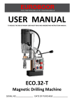
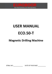
6 - Spare parts & Exploded view
1
2
3
4
5
6
7
9
10
11
12
13
14
15
16
17
18
19
20
21
22
23
24
25
26
27
28
29
30
31
32
33
34
35
36
37
38
39
40
41
51
52
53
54
55
56
57
58
59
60
61
100.4001
100.0006
100.0031
020.0096
020.0138
100.0038
020.0201
100.4041
100.0076
100.0066
100.0046
100.0071
020.0106
100.0081
100.0084
100.0101
020.0336
020.0077
020.0081
100.0116
100.0122
100.0126
020.0151
020.0106
PP.RLEU
100.0136
020.0041
020.0031
020.0036
020.0182
020.0101
PP.100/4
020.0206
020.0006
020.0016
020.0017
020.0011
100.0152
100.0002
100.0003
PPA.100/4
100.4303
100.4304
Frame
Screw SSM8x25
Washer M8
Setting Nut
Setting Screw
Magnet Base
Sensor
Slide
Rack
Screw SSM6x30
Motorholder
Screw SSM6x55
Screw SSM6x16
Brass rail set (stick)
Pressing strip
Capstan hub assembly
Power Assist (big)
End Plate
End Screw
Arm for Capstan
Motor Fixing
Screw SSM8x35
Magnet spring ball
Screw SSM6x16
Rear plate
Motorcable
Coupling nut for motorcable
Coupling nut for maincable
Main Cable Euro
Screw+washer+nut
Panel screw
Front plate
Sensor LED+cable
On/Off Switch
Fuse holder
Fuse F2A
Magnet Switch
L/R switch (push)
Control Unit 220v
Control Unit 110v
Panel Plate Assembly
Motorunit 1800W / 220v
Motorunit 1800W / 110v
100.0306
100.0459
100.4318
100.4319
100.0322
100.0536
100.4333
100.4334
100.0346
100.1310
100.0348
100.0506
100.0368
Screw
Screw
Armature 230v
Armature 110v
End Cover
Screw
Speed Control Unit 230v
Speed Control Unit 110v
Rubber Fitting Ring
Washer
Armature Speed Disk
Bearing
Carbon Brush set
62
63
64
65
66
67
68
69
70
71
72
73
74
75
76
77
78
79
80
81
82
83
84
85
86
87
88
89
90
100.4312
100.0372
100.4383
100.4384
100.4388
100.0391
100.4401
100.0458
040.0161
100.4320
100.4321
100.0426
100.4431
100.4324
100.4411
100.0446
100.0451
100.4326
100.0461
100.0466
100.0471
100.0476
100.0481
100.0486
100.4491
100.4496
100.4332
080.0351
100.4334
100.4336
Friction Clutch complete
Carbon Brush Holder
Field 230v
Field 110v
Housing
Baffle
Inner Gear Plate
Gasket
Needle Bearing
Double Gear 2
Axle 1
Circlip
Spindle Key
Spindle Gear (38T)
Adaptor Ring
Bearing
Circlip
Gear Casing
Spindle Drive Shaft
Bearing
Circlip
Adaptor Ring
Needle Bearing
Washer
Double Gear 1
Key
Axle 2
Bearing
Axle 3 (13T)
Clutch Shaft 2
92
93
94
95
96
97
98
99
99A
99B
99C
99D
99E
100
101
102
103
104
105
106
107
108
109
110
111
112
100.4526
100.4621
100.4342
040.0286
100.4344
100.4346
100.4348
100.4350
100.4351
100.4338
100.4340
100.4349
100.4353
100.4352
100.0581
080.0576
100.0571
100.4571
100.0611
100.4572
100.4573
100.4574
100.4575
100.0549
100.0617
100.4569
Key 3 (L)
Plate for Gear Casing
Clutch Shaft 1
Gear Switch
First Gear
Cylinder
Shell 25
Nut
Washer
Friction Disk 1
Brass Disk 1
Brass Disk 2
Friction Disk 2
Shell 28
Circlip
Bearing
Circlip
T/S Switch housing Red/Blue
T/S Switch Cover
Speed Potentiometer 100K
Torque Potentiometer 1K
Red Wheel
Blue Wheel
Casing Pin
Screw 6x45
T/S Switch Housing complete
12
Important notice :
Because of minor changes to our machines it is recommended to provide the framenumber of your
machine when ordering spareparts. This number can be found on front of machine at magnetic base and
frame. When you have any doubt when ordering spareparts, please contact your supplier before ordering.
13
14