1
INTELLICHEM®
WATER CHEMISTRY CONTROLLER
INSTALLATION
AND
USER’S GUIDE
IMPORTANT SAFETY INSTRUCTIONS
READ AND FOLLOW ALL INSTRUCTIONS
SAVE THESE INSTRUCTIONS
Technical Support
Phone: (800) 831-7133 - Fax: (800) 284-4151
visit www.pentairpool.com and www.staritepool.com:
Contents
IMPORTANT WARNING AND SAFETY INSTRUCTIONS..........................................i
IntelliChem Overview...................................................................................................1
Operator Controls Indicators and Alarm LEDs............................................................2
pH Settings and ORP Settings Buttons.......................................................................3
IntelliChem Controller System Power Up Sequence...................................................4
Password Protect.........................................................................................................5
Display Modes.............................................................................................................6
Auto Setup Sequence..................................................................................................6
IntelliChem Controller System Default Values.............................................................9
IntelliChem Controller Menus......................................................................................10
Navigating IntelliChem Controller Menus....................................................................11
pH Menu Description ..................................................................................................12
ORP Menu Description ...............................................................................................15
Configuration Menu ...............................................................................................18/19
Auto Setup Menu ........................................................................................................25
Saturation Index Overview ..........................................................................................25
INSTALLATION...........................................................................................................29
Mounting IntelliChem Controller Enclosure ............................................................30
Wiring the IntelliChem Controller Transformer ........................................................31
Connecting External Devices to IntelliChem Controller ..........................................32
Installing the Flow Cell and pH/ORP Sensors ........................................................33
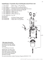
Plumbing the Flow Cell ...........................................................................................35
Connecting the IntelliChem Controller to an Automation Control System...................39
Wiring the IntelliChem Controller AC Power to Automation Filter Pump Relay...........41
Setting up EasyTouch, IntelliTouch, SunTouch Automation Control System...............43
Troubleshooting...........................................................................................................46
Tweaking pH/ORP (Calibrating Sensors)....................................................................51
Maintenance................................................................................................................52
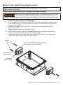
Motor Pump Head Yearly Replacement ..................................................................53
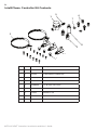
Replaceable Parts List .......................................................................................54/56
®
P/N
521363 Rev
F - 9/2015
INTELLICHEM
Controller
Installation and User’s Guide
i
IMPORTANT WARNING AND SAFETY INSTRUCTIONS
SERIOUS BODILY INJURY OR DEATH CAN RESULT IF THIS PRODUCT IS
NOT INSTALLED AND USED CORRECTLY.
INSTALLERS, POOL OPERATORS AND POOL OWNERS MUST READ
THESE WARNINGS AND ALL INSTRUCTIONS BEFORE USING THIS
PRODUCT.
Most states and local codes regulate the construction, installation, and operation of public pools and spas, and the construction of residential
pools and spas. It is important to comply with these codes, many of which directly
regulate the installation and use of this product. Consult your local building and health
codes for more information.
IMPORTANT NOTICE - Attention Installer: This Installation and User’s Guide (“Guide”)
contains important information about the installation, operation and safe use of this
product. This Guide should be given to the owner and/or operator of this product.
Before installing this product, read and follow all warning notices and instructions in this Guide. Failure to follow warnings and instructions can result
in severe injury, death, or property damage. Call (800) 831-7133 for additional free copies of these
instructions. Please refer to www.pentairpool.com for more information related to this products.
DO NOT INSTALL THE INTELLICHEM® CHEMICAL CONTROLLER WHERE IT CAN BE ACCESSIBLE TO THE
PUBLIC.
RISK OF ELECTRICAL SHOCK OR ELECTROCUTION:
BEFORE WORKING ON INTELLICHEM® CHEMICAL CONTROLLER: Always disconnect
power to the IntelliChem controller at the circuit breaker before servicing.
Failure to do so could result in death or serious injury to service person,
pool users or others due to electric shock.
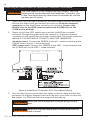
BE SURE TO DISCONNECT ALL SUPPLY CONNECTIONS BEFORE
SERVICING THE INTELLICHEM CONTROLLER. AC Power may be supplied
to the relay terminals Ex_Relay1 and Ex_Relay2 from other sources. See
page 31 for details.
This product must be installed by a licensed or certified electrician or a qualified pool professional
in accordance with the National Electrical Code (NEC), NFPA 70 or the Canadian Electrical Code
(CEC), CSA C22.2. All applicable local installation codes and ordinances must also be adhered to.
Improper installation will create an electrical hazard which could result in death or serious injury
to pool users, installers or others due to electrical shock, and may also cause damage to property.
BEFORE USING YOUR POOL, SPA OR HOT TUB, CHECK THE
pH AND SANITIZER LEVELS OF THE WATER.
Do not permit children to operate this equipment.
When mixing acid with water, ALWAYS ADD ACID TO WATER. NEVER ADD
WATER TO ACID. When adding any chemical to the pool/spa, be sure to follow
the manufacturer’s instructions thoroughly.
DO NOT MIX SODIUM HYPOCHLORITE AND MURATIC ACID
Risk of electrical shock. Connect IntelliChem controller to a ground-fault
interrupter-circuit (GFCI). Contact a qualified electrician if you cannot verify that
the receptacle is protected by a GFCI.
IF “CLEAR OVERFEED LIMIT” SETTING IS SET TO 24 HOURS, DO NOT
SET “FEED TIME” GREATER THAN 20 HOURS AS THIS WILL VOID NSF
CERTIFICATION.
INTELLICHEM® Controller Installation and User’s Guide
ii
IMPORTANT WARNING AND SAFETY INSTRUCTIONS
WARNING CHEMICAL BURN HAZARD: Make sure all pumps are
switched off at the main circuit breakers at the house before drilling into
any pipes. Securely fasten all electrical, water and chemical lines. Locate
chemical feed pumps and chemical storage tanks in a safe and secure
area.
Strictly follow the acid manufacturers safety and handling protocols
including hand, body and eye protection when transferring or handling
acid. Safety precautions should be used when handling Muriatic acid
to control pH water levels. Muriatic acid can cause serious body injury
and damage pool equipment. Extra care must be taken when installing,
maintaining and operating acid pump feed systems. Acid is dangerous to
handle and should be properly contained, transported, poured, stored,
and dispensed.
•
•
•
Check the pH and sanitizer levels of the water before use.
Periodically use an independent pH and Chlorine test kit to verify that pH
and chlorine is at a safe level. If the pH and Oxidation Reduction Potential
(ORP) or Flow Cell sensors are broken, depleted or dirty with oils, lotions,
or other contaminants, they can report inaccurate results to the system
causing incorrect water chemistry, which could harm people or equipment.
Check the IntelliChem® Controller main status display each day to ensure
there are no Alarm messages. See “Troubleshooting” on page 45 for more
information.
When using IntelliChem with a pool pump timer: The Association of Pool and Spa
Professionals (APSP) recommends that all water in a residential pool pass through
the filtration system at least once every 12 hours (referred to as pool water turnover).
However, many factors have an effect on actual pump and filter system run times. Pool
size, source of water, direct sun light, indoor/outdoor, screened and unscreened, filtration
system, cold or hot weather, swimmer load, rain, organic debris, algae, etc., are all factors
which contribute to either more or less pool pump and filter system run times. Because
of these differences, it is extremely difficult to set an initial run time (starting point) for the
pool pump and chlorinating system. Try initially setting the pool pump timer to 12 hours.
It will take a few days to get just the right amount pool pump operating time. When the
Chlorinator is wired with a pool pump timer (see page 6) results will vary greatly from one
pool installation to the next, so this should be discussed with either the pool builder or your
pool professional.
Using CO2 for pH Control
Plaster pools and pools using salt-chlorine generators typically cause a slow pH rise which
must be managed. With the IntelliChem® controller muriatic acid or carbon dioxide (CO2)
is dispensed into the filter system’s return water as needed until the Flow Cell pH sensor
detects the proper pH level. Using CO2 for pH control eliminates the need to handle and
stored acid and can be a safer method. As CO2 gas is injected into the pool water, it
dissolves and creates carbonic acid. This weak acid is very efficient at lowering pH with
the added benefit of self-limiting if the CO2 is over-fed.
INTELLICHEM® Controller Installation and User’s Guide
iii
IMPORTANT WARNING AND SAFETY INSTRUCTIONS
Most states and local codes regulate the construction, installation, and operation of public pools and spas, and the construction of residential
pools and spas. It is important to comply with these codes, many of which directly
regulate the installation and use of this product. Consult your local building and health
codes for more information.
IMPORTANT NOTICE - Attention Installer: This Installation and User’s
Guide (“Guide”) contains important information about the installation, operation
and safe use of this product. This Guide should be given to the owner and/or
operator of this equipment.
Before installing this product, read and follow all warning notices and instructions in this Guide. Failure to follow warnings and
instructions can result in severe injury, death, or property damage.
Call (800) 831-7133 for additional free copies of these instructions. Please refer to www.
pentairpool.com for more information related to this products.
Working with muriatic acid can be dangerous. When cleaning the IECG always wear rubber gloves and eye protection. Always add acid
to water, do not add water to acid. Always work in a well-ventilated area. Splashing or
spilling acid can cause severe personal injury and/or property damage. Pentair always
recommends 1:1 dilution when using full strength muriatic acid. When mixing,
remember to always add acid to water.
IMPORTANT! TAKE EXTREME CARE WHEN INSERTING THE ACID CONTAINER
INTO THE STORAGE TANK, AS THE FOIL SEAL MAY NOT BE FULLY ATTACHED.
Be sure that the pool or spa meets the requirements of the current National Electrical Code (N.E.C.) Article 680-22 and all local codes
and ordinances. A licensed or certified electrician must install the electrical system to
meet or exceed those requirements before the underwater light is installed.
READ THE FOLLOWING BEFORE HANDLING AND
WORKING WITH MURIATIC ACID (ALSO KNOWN AS
HYDROCHLORIC ACID) AND CHLORINE (SODIUM
HYPOCHLORITE)
MURIATIC ACID AND CHLORINE (LIQUID AND MIST) CAN
CAUSE SEVERE BURNS TO SKIN, MOUTH AND EYES. MAY
BE FATAL IF SWALLOWED OR INHALED. INHALATION CAN
CAUSE SEVERE LUNG DAMAGE.
IMPORTANT! CHLORINE CONTAINER
MIXING CHEMICALS WITH CHLORINE OR CHLORINE
RESIDUE IN CONTAINER CAN CREATE A DEADLY GAS OR
AN EXPLOSION.
INTELLICHEM® Controller Installation and User’s Guide
iv
IMPORTANT WARNING AND SAFETY INSTRUCTIONS
INHALATION
Inhalation of vapors can cause coughing, inflammation of the nose,
throat and upper respiratory tract and death. In case of inhalation,
move to an area of fresh air immediately.
INGESTION
Swallowing can be fatal. Contact local poison control center or
physician immediately. Give large amounts of water or milk. Allow
person to vomit. If vomiting occurs, keep head lower than hips to
avoid aspiration. If person is unconscious, turn their head to the side.
Seek immediate medical attention.
STORAGE:
Install and store container and acid in a dry, ventilated place
protected from excess heat and direct sunlight. Should be stored at
a temperature below 80°F (27°C). Be sure drainage is located away
from building and equipment.
SKIN CONTACT
Wash skin with soap and water for at least 20 minutes and remove
contaminated clothing and shoes. Contaminated clothes should be
thoroughly cleaned before re-use.
EYE CONTACT
Flush eyes immediately with water for at least 20 minutes. Seek
immediate medical attention.
PERSONAL PROTECTION
VENTILATION
Use container outside and in a well-ventilated area.
EYE PROTECTION
Use splash-resistant safety goggles.
CLOTHING
Wear chemical-resistant clothing when handling or working with acid
and chlorine.
GLOVES
Wear chemical-resistant gloves when handling or working with acid
and chlorine.
DISPOSAL
Because of its corrosive nature, muriatic acid is a hazardous waste
when spilled or discarded. Dispose of used acid at an approved
hazardous waste facility or at your municipal household hazardous
waste collection facility. Small spills of acid may be neutralized using
baking soda. Carefully pour the baking soda onto the spilled material
until the fizzing stops, then mop or scoop up the residue. Leave
cleanup of large spills to the experts; call your local fire department or
hazardous materials spill team.
READ AND FOLLOW ALL INSTRUCTIONS
SAVE THESE INSTRUCTIONS
INTELLICHEM® Controller Installation and User’s Guide
1
Overview
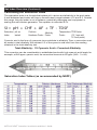
The INTELLILCHEM® Water Chemistry Controller is a pH and ORP sensing device
that dispenses correct amount of chlorine or bromine, muriatic acid or CO2 gas. The
IntelliChem controller provides continual analysis of your swimming pool water sanitation
and pH levels, providing real-time status information to dispense the proper amount of
muriatic acid (pH reducer) and chlorine or bromine for the correct sanitization and pH
balance. The IntelliChem controller operates with or without a salt chlorine generator
to provide a self-replenishing supply of chlorine generated from salt. The IntelliChem
controller can also connect to carbon dioxide (CO2) liquid gas tanks to lower pH in
your swimming pool water. When CO2 dissolves into water it produces weak neutral
bicarbonate salts which reduces pH. CO2 is environmentally friendly and produces no
secondary pollution into the treated water by salts such as chlorides or sulfates. CO2 does
not corrode metal equipment and does not require any special piping. The IntelliChem
controller supports Pentair Aquatic Systems (“Pentair”), EasyTouch®, IntelliTouch® and
SunTouch® automation control systems for pH and ORP control. The IntelliChem controller
also supports IntelliChlor® salt chlorine generator (SCG) to help manage your pool water
sanitizer levels.
Operating the IntelliChem Controller
Before operating the IntelliChem controller, it’s important to test and adjust your pool
water chemistry to the recommended pool industry levels found in this manual (see
page 19). If you are using an IntelliChlor salt chlorine generator, adjust the salt levels
to the recommended levels in the IntelliChlor (SCG) Installation and User’s Guide (P/N
520589). During normal operation, no user input is required, the IntelliChem controller
will automatically sense ORP and pH levels. The current ORP and pH levels are regularly
displayed on the control panel LCD display. Use the pH Settings or ORP Settings buttons
to view or adjust supply levels. The “Auto Setup” feature provides screen prompts for
first-time setup or standard configurations such as setup reminder times, calculating feed
times, proportional limits and alarms. For details, see page 6.
First Balance Your Pool Water
IMPORTANT: To help keep your pool water balanced follow these steps:
1. Use a Test Kit (with fresh testing reagents) to measure the pH, alkalinity,
and calcium hardness of the pool water. For greater accuracy, Pentair
recommends the AcuCheck3 Test Kit to measure pH, chlorine ppm, and
alkalinity levels (P/N 745000110). “Balanced” water has proper levels of
pH, Total Alkalinity and Calcium Hardness. This “balanced” water is neither
corrosive or scaling. The pH (0-14) value is the scale of relative acidity
or alkalinity. Recommended pH range is from 7.2 to 7.6. The IntelliChem
controller default pH value is 7.5 (see page 12).
2. Be sure the pool chlorine level is balanced. Ideal free chlorine level should
be between 1.0 - 3.0 parts per million (ppm).
3. Use the online Langelier Saturation Index (LSI) calculator to diagnose
the water balance in your pool or the IntelliChem controller built-in LSI
calculator (see page 28-31). Refer to:
http://www.pentairpool.com/pool-owner/resources/calculators/langelier/
Note: A Saturation Index value of 0 indicates the water is chemically in balance. If the
Index is a minus (-) value, corrosive tendencies are indicated. If the Index is a plus (+)
value, scale-forming tendencies are indicated. A Saturation Index value between +0.5
to -0.5 is considered satisfactory in a swimming pool. See Saturation Index menu
on page 28.
INTELLICHEM® Controller Installation and User’s Guide
2
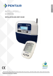
Operator Controls, Indictor and Alarm LEDs
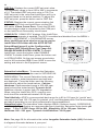
CONTROL PANEL DESCRIPTION
2
3
pH
SETTINGS
ORP
SETTINGS
4
1
pH
OK 7.46
Mixing 00:07:03
ORP OK 450
Mixing 00:07:54
FLOW
9
ALARM
5
MENU
Select
6
7
8
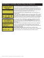
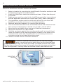
Control Buttons and LEDs:
1 Liquid Crystal Display (LCD) with backlighting: Displays system status information
and the IntelliChem® Controller main menu. Display backlight and menu on and off
time (30 seconds to 24 hours) can be set via the “LCD Timeout” menu feature. See
“Configuration” menu page 17).
Display viewing modes: Select between two display modes: Basic: pH and ORP
status with alarms messages. Advanced: pH, ORP, status, alarm messages and
process timers.
2 pH Settings button: Access the pH settings (see page 3).
3 ORP Settings button: Access the Oxidation Reduction Potential (ORP) settings
(see page 3).
4 Flow LED: Green LED on indicates flow is detected. LED will blink during flow delay.
LED off indicates no flow in the system. If flow is not present, no chemical feeding
or IntelliChem controller activity is allowed. LED brightness can be adjusted via the
Configuration “Display Mode” menu (see page 17).
5 Left arrow button: Scroll through sub-menu items or move cursor left when editing a
setting.
6 Menu button: Access the main menu (see page 11). While in menu mode, used to
exit a menu level. All items are saved as soon as they are changed.
7 Right arrow button: When in menu mode, selects menu main and sub-menu item,
scroll through sub-menu items or move cursor right when editing a setting.
8 Alarm LED: LED is on if an alarm condition occurs. Display shows alarm message
and status (see page 48). LED brightness can be adjusted via the Configuration
“Display Mode” menu (see page 17).
9 Up/Down arrow button: When in a menu mode, use / to scroll through main
menu and sub-menu items, increase, decrease or change a setting or value. Also,
used for moving to next sub-menu page 1/2 - 2/2.
INTELLICHEM® Controller Installation and User’s Guide
3
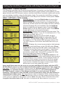
pH Settings and ORP Settings Buttons
pH Dosage (dispense acid)
DO NOT manually feed pH (acid) and ORP sanitizer (chlorine) at the same time without sufficient water flow through the piping
system. Combining these two chemicals without sufficient water flow for mixing
will result in the formation of hazardous gas. This menu item will be displayed as
Override [Wait] during no-flow and flow-delay time period.
pH
SETTINGS
ORP
SETTINGS
pH Settings button: Press the pH Settings
button to access the pH dosage settings.
pH Settings
Override [Dose]
Level Gauge:
5
Limit cleared
ORP Settings button: Press the ORP Settings button
ORP Settings
to access the Oxidation Reduction Potential (ORP)
Override [Dose]
settings. The ORP is the sanitization quality of the
Level Gauge:
5
Limit: [Clear
]
water of a given solution.
Note: To exit pH Settings and ORP Settings, press the MENU button.
Password Protect: The pH Settings and ORP Settings screens are not accessible
when the Password Lock is set to “ALL”. Set the Password Lock to “OFF” or “MENU” to
access these screens (see page 5).
Override (pH): Press the / Right or Left arrow button to toggle between “Dose”
or “Stop”. Select “Dose” to dispense muriatic acid or CO2 and select “Stop” to stop
dispensing acid or CO2 (pH Settings LED is on). To exit, press the MENU button or
press the Down button to select the “Level Gauge” feature. The Override feature is
not available when CO2 is setup to “Feed to Setpoint.”
Override (ORP): Press the / Right or Left arrow button to toggle between “Dose”
or “Stop”. Select “Dose” to dispense chlorine (or bromine) and select “Stop” to stop
dispensing chlorine (ORP Settings LED is on). To exit, press the MENU button or press
the Down button to select the “Level Gauge” feature. The Override feature is not
available when IntelliChlor is setup to “Feed to Setpoint.”
Level Gauge indicator: Press the / Up/Down button to select this feature. The
level gauge (volume based) and hour glass (time based) icon is a visual representation
of the amount of acid (pH Settings) or chlorine (ORP Settings) available in the
container. Press / six times to fill the gauge (container full). The indicator displays
six horizontal bars when full. The level gauge is not available if the doser is unable
to determine the pump dispense rate, the supply volume, or if there is no supply
“reminder” set up (see page 13-15). The gauge is displayed as an “hour glass” if the
supply is based on time rather then volume (see page 6)
Limit [Clear]: Press the / to select this feature. Press the / to clear the current
dosage limit timer. After pressing the button, “CLEARED” is displayed, indicating that
the current dosage limit is cleared.
INTELLICHEM® Controller Installation and User’s Guide
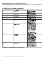
4
IntelliChem® Controller System Power Up Sequence
IntelliChem® Controller
v1.060 09/04/2014
Pentair Aquatic Systems
AUTO CALIBRATION
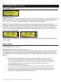
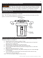
Power-up Sequence: During power-up the IntelliChem®
Controller displays the initialization screens before the
main status screen is displayed. During this initial power up
sequence, the IntelliChem controller performs an internal self
test and continues with a system calibration. The first screen
includes the current software version and date.
AUTO CALIBRATION is displayed each time IntelliChem is
powered up.
AUTO CALIBRATION In the next auto-calibration sequence the pH and ORP meters
pH 6.35 7.65 OK are tested with on-board circuitry and calibrated to the built-in
reference devices. An out-of-tolerance condition is immediately
ORP 738 398 OK
reported as an error so the user can have the unit serviced.
***PASSED***
IntelliChem Auto
__Setup Wizard__
Press MENU to go
to each new step
The very first time IntelliChem controller is powered up and
after a factory reset, the Auto Setup Wizard start screen is
displayed. Otherwise access the wizard from the main menu
(see page 6).
Awaiting
The normal start up screen will simply be this one, awaiting
POWER&FLOW DELAY Power On & Flow Delay. The countdown timer shows the
H:00 M:14 S:18
remaining time before the unit starts reading the probes and
please wait...
controlling the doser.
Main
Status Screen: After IntelliChem controller has
pH OK 7.5
completed the Flow Delay the main status screen displays the
measurements of the connected pH and ORP sensors.
ORP OK 450
INTELLICHEM® Controller Installation and User’s Guide
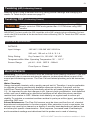
5
Set Password Protect
The password protect feature prevents access to certain menus and prohibits all menu
changes and manual feeds. For more information, see Set Password on page 18.
To set the password protect:
Set Password
PW
[1234]
Lock
[Off ]
Locked - Please enter
password
> 1234
1. Press MENU / Configuration
and / Set Password.
2. Set Password (PW): Press the / Up/Down
arrow button to select the first password digit (0-9).
3. Press the / Right/Left arrow button to move the
cursor to the next digit.
4. Press the / Up/Down arrow button to select the
second password digit. Repeat steps 3 and 4 for the
third and fourth password digit.
5. Press the Right arrow button to move the cursor
to the Lock Menu setting.
6. Press the / Up/Down arrow button to select
OFF: Do not enable control panel button lockout.
ALL: Lockout MENU, pH Settings and ORP Settings
buttons). Tank Levels cannot be changed.
MENU: Lockout MENU button (not pH Settings and
ORP Settings buttons). Setpoints or Sat Index values
TA, CYA, CH cannot be changed.
7. To exit, press the MENU button (press three times to
return to the main screen.
Tip: Setting the password 0000 allows you to enter a protected screen by pressing MENU. Also, once the password is entered, access is granted for the duration specified by the Menu timeout setting in the Configuration/Display Mode menu (see page 17).
Password Protect and IntelliTouch®, EasyTouch® and SunTouch®
Control Systems
Note: If the password lock is enabled from IntelliChem controller it will also be
locked out on the IntelliTouch, EasyTouch or SunTouch automation control system.
When IntelliChem is controlled by the IntelliTouch, EasyTouch or SunTouch control
system, if the password is set and locked on the IntelliChem, it cannot be changed from
the automation control panel. To change a “LOCKED” password from the automation
system, enter the password on the IntelliChem controller, it will remain active for the
Menu Timeout MM:SS period. During that time, the automation system will be able to set
the appropriate settings, just as you would from the IntelliChem controller front panel.
Receiving updated settings from automation will continue to extend the Menu Timeout, just
as if you’re accessing the menu on the IntelliChem controller itself.
INTELLICHEM® Controller Installation and User’s Guide
6
H CO2
OR
The- displays
shows t
Display Modes
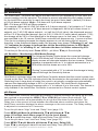
The main IntelliChem® Controller status screen can be setup to display basic or advanced
system information. To setup the Display Mode, see “Configuration” menu on page 17.
The Basic display mode shows the current pH and ORP measurements including a
message describing any existing pH (line two) and ORP (line four) alarms. The Advanced
display mode shows all the current measurements and alarm messages as well as dose
and mix timers showing the progress of those processes.
Basic display mode
pH
>OK 7.4
-.72 Scaling
ORP OK
730
Monitoring
The Basic mode displays the current pH and ORP
measurements (pH in10th and ORP in 5mV) with any alarms
Note: Alarms are displayed on all Basic and Advanced modes.
>OK or <OK is displayed as soon as the value exceeds
alarm trip point. That is replaced with “HIGH/LOW” after the
Advanced display mode Displays three different Alarms. The example screen shows:
Dose limit, high reading and chemical tank low alarm. These
pH HIGH 7.91
can co-exist. The advanced mode displays the current pH and
pH Dose Limit
ORP high precision measurements (extra digit. e.g. pH=100th ORP OK 683
ORP=1mV resolution), alarms, tank levels, process messages
Mixing 00:07:54
and timers.
Basic and Advanced Display with Error Messages
NO FLOW DETECTED If IntelliChem detects the pool water circulation pump is not
active, a NO FLOW message is displayed. ORP and pH values
Check pump, flow
are not measured when there is no flow, and therefore not
Cell, filter,
displayed.
and valves.
Auto Setup Sequence
Use the Auto Setup feature for first-time setup or standard configurations. Follow the onscreen prompts and enter information about your system configuration (pH/ORP internal
or external pumps, pool size, filter time, chemical container size etc). IntelliChem uses
this information to automatically setup reminder times, calculate feed times, proportional
limits and alarms. The following describes the Auto Setup screen. Press the MENU button
to access the Auto Setup menu. To change a menu setting or value press the / Up/
Down arrow button. Press the MENU button to save each selection.
Dosing will
resume when you
_exit this menu_
Press any button
To exit Auto Setup,
press
INTELLICHEM® Controller Installation and User’s Guide
IntelliChem Auto
__Setup Wizard__
Press MENU to go to
each new step
Press MENU / Auto Setup
Previous Values: Use to recalculate new dose times etc., if no custom settings exist. Not
recommended for custom settings; use the menu directly to make these changes.
Reset All: Make major configuration changes that may have conflicts with previous
settings.
Would you
like to use
previous values?
[Yes | Reset All]
Press UP/DWN to select.
Press MENU. (Resetting
defaults and Password).
Press MENU.
7
Auto Setup Sequence (Continued)
What is your
What size is the
Hardware Setup? body of water?
ORP
pH
Volume: 10.0K
[L_Pump R_pump]
Units: gal-US
How long does
What is the pH
your
filter
run?
Container Size?
Daily:H:08 M:00
4.00 gal-US
Gauge: 6
Press the / Up/Down arrow button to Press the MENU
scroll through the controller configurations. select next screen
Enter Container Size info.
Press MENU. “Is your pool
water balanced?
What is your
What size is the
How long does
What is the pH
Hardware Setup?
body
of
water?
your
filter
run?
Container Size?
pH
ORP
Volume: 10.0K
Daily: H:24 M:00
1.0 gal-US
[L_Pump ICHLOR]
Units: gal-US
Gauge: 6
What is your
What size is the
How long does
What is the pH
Hardware Setup?
body of water? your filter run? Container Size?
pH
ORP
Volume: 10.0K
Daily: H:24 M:00
1.0 gal-US
[L_Pump EX_IC*]
Units: gal-US
Gauge: 6
Enter doser pump
What is your
What size is the
How long does
Hardware Setup? rated output for
body of water? your filter run?
ORP: 50 GPD
pH
ORP
Volume: 10.0K
Daily: H:08 M:00
[L_Pump RELAY1]
Units: gal-US
(*) EX_IC: IntelliChlor® Salt Chlorine Generator (Commercial
What is the pH
model only) Output on RELAY #1.
Container Size?
EX_IC also set ORP sensitivity = Off, whereas other cases
4.0 gal-US
are LOW. Selects Dose-by-Time, Dose Time set to 24:00:00
Gauge: 6
(all day) Removes container gauge. Turns off supply
Enter Container Size info.
reminder (Default).
Press MENU. “Is your pool
water balanced?
What is your
What size is the
Enter doser pump
How long does
Hardware Setup? rated output for
body of water? your filter run?
pH
ORP
Volume: 10.0K
pH: 50 GPD (1-400)
Daily: H:08 M:00
[RELAY2 ICHLOR]
Units: gal-US
Select “Use Time” (“0”)
What is the pH
if the doser pump’s
Container Size?
GPD (gallons-pe
1.0 gal-US
r-day) feed rate is
Gauge: 6
What size is the
Enter doser pump
What is your
Hardware Setup? rated output for
body of water?
Volume: 10.0K
pH: 50 GPD
pH
ORP
Units: gal-US
ORP: 50 GPD
[RELAY2 EX_IC]
How long does
your filter run?
Daily: H:08 M:00
What is the pH
Container Size?
4.00 gal-US
Gauge: 6
Enter ORP info. Press
MENU. “Is your pool
Continue on next page.
water balanced?
INTELLICHEM® Controller Installation and User’s Guide
8
Auto Setup Sequence (Continued)
Enter doser pump
What size is the
What is your
Hardware Setup? rated output for
body of water?
pH: 50 GPD (1-400)
Volume: 10.0K
ORP
pH
Units: gal-US
[RELAY2 RELAY1] ORP: 50 GPD
Daily: H:08 M:00
[RELAY2 DUAL]
[CO2/R2 ICHLOR]
How long does
your filter run?
What is the pH
Container Size?
1.0 gal-US
Gauge:
6
What is your
What size is the
How long should
Hardware Setup?
body of water?
CO2
dose
be
Volume: 10.0K
pH
ORP
H:00 M:05 S:40
[CO2/R2 L_PUMP]
Units: gal-US
Enter Container
size info. Press
MENU. “Is your pool
water balanced?
How long does
your filter run?
Daily: H:08 M:00
What is the pH
pH Chem
Reminder in:
H:00 M:00
Container Size?
What size is the
How long should
What is your
body of water?
each CO2 dose be?
Hardware Setup?
Volume: 10.0K
H:00 M:05 S:00
pH
ORP
Units: gal-US
[CO2/R2 ICHLOR]
your filter run?
How long does
your filter run?
Daily: H:08 M:00
What is your
How long should
Hardware Setup? each CO2 dose be
pH
ORP
00:00:00
[CO2/R2 EX_IC]
1.0 gal-US
Gauge:
6
pH Chemical
Reminder in:
H: 100 M: 00
What size is the
body of water?
Volume: 10.0K
Units: gal-US
Daily: H:08 M:00
Enter Reminder
info. Press MENU.
“Is your pool water
balanced?
How long does
your filter run?
Daily: H:08 M:00
Enter Reminder
info. Press MENU.
“Is your pool water
balanced?
How
does
pH long
Chemcal
your
filter run?
Reminder
in:
Daily:
H:08M:00
M:00
H:00
What is your
Enter doser pump
Hardware Setup? rated output for
pH
ORP
ORP: 50 GPD
[CO2/R2 RELAY1]
How long should
What size is the
00:00:00
Volume: 10.0K
Units: gal-US
each CO2 dose be body of water?
How
Howlong
longdoes
does
your
yourfilter
filterrun?
run?
Daily:
Daily:H:08
H:08 M:00
M:00
How long does
How
long does
pH Chemcal
your
filter run?
Reminder
in:
What is the ORP
Container Size?
Daily:
H:08
M:00
H:100
M:00
INTELLICHEM® Controller Installation and User’s Guide
4.00 gal-US
Gauge:
6
Enter Container
size info. Press
MENU. “Is your pool
water balanced?
Continue on next page.
9
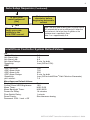
Auto Setup Sequence (Continued)
YES
Finished Setup.
Verify your new
settings in the
pH & ORP menus!
NO
Is your pool
water balanced?
[No]
Balance water
chemistry before
beginning automatic
control
Note: The units used for dose size in the main menus
will automatically be set to milliliters(ml) if either the
pool volume is set to less than 4k gallons or the
container size is specified in liters.
Note: 1 oz = approximately 3 ml.
IntelliChem Controller System Default Values
pH
pH Set Point: 7.5
pH Alarm High: 7.8
pH Alarm Low: 6.8
pH Alarm Delays:
5 min. for both
Low (Off for CO2)
Sensitivity:
ORP
ORP Set Point: 700
ORP Alarm High: 750
650
ORP Alarm Low:
ORP Alarm Delays:
5 min. for both
Sensitivity:
Low (Off for IntelliChlor® Salt Chloriine Generator)
pH Lockout:7.8
Miscellaneous Default Values
Display Mode:Basic
Control Panel LED Brightness:
10%
Menu Timer:M:02 S:30
M:00 M:20
Menu Backlight Timer:
Power-On Delay:
14 minutes
Flow Switch Delay:
1 minute
Dose Priority:
Simultaneous dosing
Password 1234 - Lock = Off
INTELLICHEM® Controller Installation and User’s Guide
10
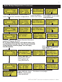
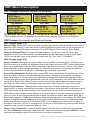
MENUS
MAIN SCREEN
PH MENU
(page 11)
pH Dosage (Page 1/2) Dosage (For liquid; Volume/Time):
(For CO2; Time or to set point): Mixing Time: H:24 M:59
pH Dose by Volume (Page 2/2) Dose: [0-9999], Limit: [0-64350],
Units: [oz/ml], Clear [Manual]
pH Dose by Time (Page 2/2) Dose: [00:00:00], Limit: [00:00:00], Clear: [Power-On]
pH Dose to Setpoint (Page 2/2) Limit: [00:00:00], Clear: [24hr Flow]
pH Setpt: 7.5 (use Left/Right button to adjust pH set point)
pH Tweak - reading = 7.xx tweak: 0.0 (+/- 0.3)
pH Supply (Page 1/2) Units: gal-US/gal-UK/Liters/Time, Chemical: [Acid, pH-, Base, pH+] Page 2/2 - Capacity: 0.000-200.00 gal-US/galUK/Liters - Gauge: Egg timer or tank gauge Page 2/2 Time: Reminder in: H:100 M:00
Sensitivity: - [Low/High/Off] - Full Dose at 0.5pH (Low - Liquid, CO2),
(High 0.2pH from set point).
pH Alarms: Page1/2 High 7.8 - Delay 00:05:00 - Page 2/2 Low: 6.8 Delay 00:05:00
ORP MENU
ORP Dosage (Page 1/2) Dosage (For liquid; Volume/Time):
(For SCG; Time or to set point): Mixing Time: H:24 M:59
ORP Dose by Volume (Page 2/2) Dose: [0-9999], Limit: [0-64350], Units: [oz/ml], Clear [Manual]
ORP Dose by Time (Page 2/2) Dose: [00:00:00], Limit: [00:00:00], Clear: [Power-On]
ORP Dose to Setpoint (Page 2/2) Limit: [00:00:00], Clear: [24hr Flow]
ORP Setpt: 700 (use Left/Right button to adjust ORP set point)
ORP Tweak - reading = xxx tweak: 0.0 (+/- 50mV)
ORP Supply (Page 1/2) Units: gal-US/gal-UK/Liters/Time, Chemical: [Chlorine/Bromine] Page 2/2 - Capacity: 0.000-200.00 gal-US/galUK/Liters - Gauge: Egg timer or tank gauge Gauge: Egg Timer or tank gauge - Page 2/2 Time: Reminder in: H:100 M:00
Sensitivity: - [Low/High/Off] - Full Dose at 50 mV ORP (Low - Liquid),
(High 20 mV from set point, Off (IntelliChlor OFF)
ORP Alarms: Page1/2 High 750 - Delay 01:00:00 - Page 2/2 Low: 650 Delay 02:00:00
(page 14)
SAT INDEX
See page 24 for details - pH: 7.5 - Temp: 00°F - CH: xxx - SLT: xxx - TA:xx = CYA: xx Recalc/Tab:
AUTO SETUP
See page 6 for details
CONFIGURATION
Pool Details:Volume: 0.2K-230K (200-230,000 Liters max) Units:
Gal US (gal-US/gal-UK/Liters), Daily Hrs/Mins
Display Mode: Display Mode: Basic/Advanced, Brightness Front LEDs: (0-100%),
Menu/BkLt Hrs/Mins. (24 hrs -30sec.)
Delays: Power-on: 1-60 mins. (15min default) - FlowSwitch: 1-60 mins. (1 min default) Doser/Probe: Seconds 0,15,30,60secs.
Set Password: PW [1234] - Lock [OFF/MENU/ALL]
Preferences: pH Lockout: 7.8, Preferences 2/2: Saturation Index, Alarm: +/- 0.3,
Dose Priority: [Simultaneous pH Priority]
Diagnostics: Software Rev, Meter Test {Auto Calibration),
Probe Test (Open Probe Test) Timers,
Chlorinator, Status Codes, Factory Reset, Self Test Sequence
Hardware: pH Control: 1/2 Doser Type [Internal Pump, External/Relay,
CO2 Ext/Relay, None] - pH Control 2/2 Flow: xx GPD See page 22 for details
(page 17)
INTELLICHEM® Controller Installation and User’s Guide
11
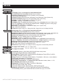
Navigating IntelliChem® Controller Menus
The following examples show how to navigate the main menus and sub-menus. Press
the MENU button to access the main menu. Press the Right arrow button to select
a menu item and select items in a sub-menu. Press / to select previous/next item
on a page. To change a menu setting or value press the / Up/Down arrow button.
Press the MENU button to exit and return to the previous menu items. Note: Settings are
automatically save when changed.
Example: To change the pH dosage settings (pH Dosage screens 1/2 and 2/2):
Press MENU / pH Menu pH Dosage
pH Menu
ORP Menu
Saturatn Index
Auto Setup
ORP Menu
Saturatn Index
Auto Setup
Configuration
Dosage
pH Setpt: 7.5
pH Tweak
pH Supplies
pH Dosage
1/2
Dose: by Volume
Mixing Time:
H:00 M:59
pH Dosage
2/2
Dose Limit Units
3
21
[oz]
Clear [Power-On]
pH Dosage
1/2
Dose: by Volume
Mixing Time:
H:09 M:59
pH
2. Press the Right arrow button to select the
pH menu.
3.Press arrow button to select pH Dosage (page
1 of 2). Press / to toggle between pH Dosage
page 1/2 and page 2/2.
4. From pH Dosage page 1/2, press the to select
Dose (feed method). To change the feed method
press / to change the selection: “by Volume” or
“by Time”.
pH
pH Menu
ORP Menu
Auto Setup
Configuration
1. Press the / Up/Down arrow button to scroll
through the main menu items. For this example
choose pH menu.
OK 7.46
Mixing 00:07:03
ORP OK 450
Mixing 00:07:54
5. Press the to select the next item. The cursor
moves down to the “Mixing Time” hours setting
(H:00).
6. Press the / to adjust the Mixing Time hours
between feeding acid. Press to select the
minutes. Press
/ to adjust the minutes. After adjustment, the
display shows the new setting. Note: Press either
/ button to scroll forward or backwards within
this sub-menu.
7.Select 1/2 page indicator. Press the / buttons to
select the next pH Dosage screen (2/2).
8.Use / buttons and / buttons to select and
change the “Dose” (amount of liquid dispensed
before waiting for a mix time), Limit (amount of
liquid dispensed in one day, Units (apply to dose
and limit) and clear dose limits setting.
9. Press the MENU to return to the previous pH
Dosage page 1/2 menu items.
10. Press the MENU again to exit pH Dosage menu.
Note: All settings are immediately save when
changed.
INTELLICHEM® Controller Installation and User’s Guide
12
pH Menu Description
Menu
ORP Menu
Saturatn Index
Configuration
by Volume
pH Dosage
2/2
Dose Limit Units
1200 64100 [mL]
Clear [Manual]
pH
Dosage
pH Setpt: 7.2
pH Tweak
pH Supplies
by Time
pH Dosage
Dose: by Time
Mixing Time:
H:00 M26
pH
pH Dosage
2/2
Dose 00:33:45
Limit 04:14:00
Clear [Power-On]
1/2
by Setpoint
pH Dosage
2/2
Dose to Setpoint
Limit 00:08:00
Clear [24hr ]
To access the pH Menu: Press MENU pH Menu pH Dosage - The ph Dosage
screen 1/2 displays the current dose method (by Volume, Time or to Setpoint).
pH Dosage (for Internal and External Pumps)
pH Dosage (page 1/2)
Mixing Time: Select the amount of time in hours and minutes that the IntelliChem®
Controller will wait in between pH feeding. It should be set to allow sufficient mixing time
for the chemicals to become distributed throughout the pool. The pH Mixing Time is set by
Auto Setup.
Dose (by Volume/Time): Choose the feed method: “by Volume” and “by Time” are
available choices for liquid dosers, as determined by the hardware setup. If CO2 is
selected, then the available choices are “by Time” and “To Setpoint”. If pool volume is less
than 4k gallons, these units automatically get set to milliliters (ml) for better resolution.
pH Dosage (page 2/2)
Dose (Volume): Displays the current dose size (0-9999) in ounces [oz] or milliliters [ml].
Set the amount of ounces (or milliliters) that the IntelliChem controller will feed pH (acid)
each time the IntelliChem controller calls for pH chemicals. The Dose (Volume) is set by
Auto Setup wizard based on pool volume and filter run time.
Dose (Time/Setpoint): Displays the current pH dose (feed) time. If pool volume is less
than 4k gallons, these units automatically get set to milliliters (ml) for better resolution.
Sets the amount of time in hours, minutes and seconds that the IntelliChem controller will
feed pH (acid) each time the IntelliChem controller calls for pH chemicals. The pH dose
time is set by Auto Setup. The Dose (Time) is set by Auto Setup wizard based on pool
volume and filter run time. Dose (to Setpoint) does not have a dose amount, only a time
limit.
Limit (Time/Volume): Displays the current feed limit. Sets the maximum amount of
time/volume in hours, minutes and seconds or volumetric units that will be allowed to
feed pH chemicals. As a safety feature, the IntelliChem controller will only allow a certain
amount of pH chemicals to feed into the system in a 24 hour period. Set the maximum
amount of time in hours (0-24) that will be allowed to feed. The IntelliChem controller
tracks each dose time, and adds them together. When the maximum dose time is reached
or exceeded, the ORP feed system is prevented from feeding until the next 24 hour period
begins, or when the feed timers are cleared manually. The default pH Limit is based on a
safe limit of 2 ppm of the size of the pool, up to a 5 oz maximum. The Limit (Time/Volume)
is set by Auto Setup wizard based on pool volume and filter run time.
Continue on next page.
INTELLICHEM® Controller Installation and User’s Guide
13
pH Menu Description (Continued)
pH Dosage (page 2/2) Continue
Clear: Select Power-On to clear the pH dose limit time when IntelliChem® Controller is
powered on. Select Manual to manually clear the pH dose limit timers and select 24 Hrs to
clear timers automatically each 24 hour period of continuous operation. To protect the pool
water, IntelliChem controller will automatically shutdown pH and ORP feed control and
display an alarm message if IntelliChem controller (or any other dispensing device) runs
non-stop for more than the selected Limit time or volume. This prevents IntelliChem from
non-stop feeding pH reducer, because of a sensor error or external problem with the pool.
This allows you to evaluate the pool chemistry before continuing with pH feeding.
pH Set Point
Displays the current pH set point value. Adjust the pH set point to meet pool and spa
chemistry standards. The adjustable range is from 7.2 to 7.6 in increments of 0.1. The
default pH set point value is 7.5.
To adjust the acid feed pH set point: Press MENU pH Menu pHSetpt
Press / to decrease or increase the current pH set point value.
Note: When using CO2, parameters are the same as above.
pH Tweak
The exact reading of each individual pH sensor can vary because of water makeup and
variances in probe condition age, etc. The pH Tweak menu feature allows you to adjust
the pH sensor reading to match the manual reading taken. The adjustable range is +/- 0.3.
After adjusting the pH value, the main screen should now display the same value as the
manual reading.
To adjust the pH sensor level:
Press MENU / pH Menu pH Tweak
The current value is displayed (reading = x.xx). Press / to adjust the pH sensor level
(+/- 0.3). To remove the tweak, set the level back to 0 (zero).
pH Supplies
pH Supply (page 1/2)
Units: Select gal-US, gal-UK, Liters or Time (hours/minutes)*.
Chemical: Use Acid, (pH -) or Base (pH+).
1/2
pH Supply
2/2
Capacity:
4.00 gal-US
Gauge:
3
pH Supply
Reminder in:
H:1000 M:00
Gauge:
2/2
6
pH Supply
Unit: USGal
Chemical:
[Acid, pH-]
pH Supply (page 2/2)
Capacity: Select from 0 to 200 maximum gal-US, gal-UK, or Liters.
*Time (Reminder in: H:xxx M:xx) If the supply Units were set to Time, the Capacity
feature becomes a Reminder feature, as in an egg-timer. This can be used to trigger an
alarm, based on cumulative feed times as to when to check the CO2 cylinder. Set the
reminder time in hours (0-8760) and minutes (00-59) on ORP Supply page 2/2. Note:
Entering the hours and minutes time (H:00 M:00) will display the hour glass icon on the
main screen.
Level Gauge (liquid only): Displays level gauge when using liquid chemical doser. Tank
icon symbol is used for liquid chemical configurations that include valid supply and doser
feed rate information.
INTELLICHEM® Controller Installation and User’s Guide
14
pH Menu (Continued)
pH Sensitivity
The IntelliChem® Controller can adjust the feed times for pH depending on how close the
current reading is to the set point. This helps to prevent overshooting and makes it easier
for the IntelliChem controller to reach the exact set point. Note: Low = (default) Full dose
at 0.5 pH above setpoint. High = Full dose at 0.2 pH above setpoint.
Off = Full dose at 0.005 pH above setpoint
For example: When set to LOW (full dose at 0.5 above setpoint), if pH setpoint is 7.2 and
pH reading is 7.7 or above, a full dose amount is dispensed. As the pH comes closer to
setpoint, say 7.45 (0.25 above setpoint - or- half the 0.5 pH value), the dispensed amount
will be 1/2 of the specified dosage. And, at 0.05 (1/10th of 0.5 value) above setpoint (7.25),
the dosage will be 10% of that specified in the dosage menu. In that case, if the dosage
was specified to be 10 ounces, IntelliChem controller will dispense only 1 ounce at a time.
This can be confusing because the display appears to not be dosing the full amount;
therefore, in the Advanced display mode, the process timer shows “%Dosing 0.1 oz”, the
“%” indicates the dosage is reduced due to this Sensitivity feature. In SPA Mode,
the leading “s” in “sDosing 0.1 oz” indicates the dose is further reduced by 25%.
To set the pH Sensitivity level: Press MENU - pH Menu / pH Sensitivity
pH Sensitive - Monitoring in SPA Mode (Dosing)
The Advanced display mode shows the current pH dosage.
pH >OK 7.28
If both SPA Mode and %Sensitivity are active, the Advanced
Monitoring
display screen will alternate between the two screens. “Dosing”
pH OK
7.25
message is preceded with an “s” to indicate automation is in
sDosing 0.1 oz
SPA mode and the doses are cut to 25%.
pH >OK 7.28
Monitoring
“Dosing” is preceded with a “%” to indicate the dosage is being
pH OK
7.25
reduced through the Sensitivity feature.
%Dosing 0.1 oz
Spa Mode is activated when the IntelliChem Controller detects that the control system has
turned on the Spa. The SPA indicator should be illuminated on the automation control panel.
Switching from a large body of water like a pool to a typically a smaller spa automatically
reduces the dispensed dosage to 25% of a normal dose. The IntelliChem’s Advanced
display precedes the Dosing message with a “s” to indicate it is in this mode. This feature is
only available if the IntelliChem Contrroller is connected to a Pentair control system.
pH Alarms
The IntelliChem controller automatically displays a screen message indicating the pH level
has reached or exceeded the HIGH (7.8) or LOW (6.8) pH alarm level settings. The
IntelliChem controller will automatically set a high and low alarm for the pH level. The
Delay time is the amount of time between the detected alarm condition and when the
IntelliChem controller displays the alarm message on the main screen. The Delay setting
is adjusted in increments of 15 seconds.
To set the pH alarm “High” level and “Delay” time (page 1/2):
Press MENU pH Menu pH Alarms / pH Alarms /
(page 1/2 is High Level Alarm, page 2/2 is Low Level Alarm)
Press to select the alarm, High level and Delay Time (00:50:00).
To set the pH alarm “Low” level and “Delay” time (page 2/2):
Press MENU / pH Menu pH Alarms / Low / Delay (2/2)
Press / to change pH alarms Low level and Delay Time (00:05:00).
INTELLICHEM® Controller Installation and User’s Guide
15
ORP Menu Description
ORP Dosage (dispense chlorine or bromine)
by Volume
ORPDosage
2/2
Dose Limit Units
1200 64100 [mL]
Clear [Manual]
ORP
Dosage
ORP Setpt: 700
ORP Tweak
ORP Supply
ORP Dosage
Dose: by Time
Mixing Time:
H:00 M26
pH Menu
Menu
Saturatn Index
Configuration
ORP
by Time
ORPDosage
2/2
Dose 00:33:45
Limit 04:14:00
Clear [Power-On]
1/2
by Setpoint
ORPDosage
2/2
Dose to Setpoint
Limit 00:08:00
Clear [24hr ]
To access the ORP Menu: Press MENU ORP Menu ORP Dosage - The
ORP Dosage screen 1/2 displays the current dose method (by Time or to Setpoint).
ORP Dosage (for Internal and External Pumps)
ORP Dosage (page 1/2)
Mixing Time: Select the amount of time in hours and minutes that IntelliChem will wait in
between ORP dosing. It should be set to allow sufficient mixing time for the chemicals to
become distributed throughout the pool. The ORP Mixing Time is set by Auto Setup.
Dose (by Volume/Time): Choose the feed method: “by Volume” and “by Time” are
available choices for liquid dosers, as determined by the hardware setup. If IntelliChlor
(SCG) is selected, then the available choices are “by Time” and “To Setpoint”.
ORP Dosage (page 2/2)
Dose (Volume): Displays the current dose size (0-9999) in ounces [oz] or milliliters [ml].
Set the amount of ounces (or milliliters) that IntelliChem will dose ORP (chlorine/bromine)
each time IntelliChem calls for ORP chemicals. The Dose (Volume) is set by Auto Setup
wizard based on pool volume and filter run time. If pool volume is less than 4k gallons,
these units automatically get set to milliliters (ml) for better resolution.
Dose (Time/Setpoint): Displays the current ORP dose (feed) time. If pool volume is less
than 4k gallons, these units automatically get set to milliliters (ml) for better resolution.
Sets the amount of time in hours, minutes and seconds that IntelliChem will feed ORP
(chlorine/bromine) each time IntelliChem calls for ORP chemicals. The ORP dose time is
set by Auto Setup. The Dose (Time) is set by Auto Setup wizard based on pool volume
and filter run time. Dose (to Setpoint) does not have a dose amount, only a time limit.
Limit (Time/Volume): Displays the current feed limit. Sets the maximum amount of
time/volume in hours, minutes and seconds or volumetric units that will be allowed to feed
ORP chemicals. As a safety feature, the IntelliChem will only allow a certain amount of
ORP chemicals to feed into the system in a 24 hour period. Set the maximum amount of
time in hours (0-24) that will be allowed to feed. IntelliChem tracks each dose time, and
adds them together. When the maximum dose time is reached or exceeded, the ORP feed
system is prevented from feeding until the next 24 hour period begins, or when the feed
timers are cleared manually. The default ORP Limit is based on a safe limit of 2 ppm of
the size of the pool, up to a 5 oz maximum. The Limit (Time/Volume) is set by Auto Setup
wizard based on pool volume and filter run time.
Clear: Select Power-On to clear the ORP dose limit time when IntelliChem is powered
on. Select Manual to manually clear the ORP dose limit timers and select 24 Hrs to clear
timers automatically each 24 hour period of continuous operation.
INTELLICHEM® Controller Installation and User’s Guide
16
ORP Menu Description (Continued)
ORP Set Point
Displays the current ORP set point value. Adjust the ORP set point to meet pool and spa
chemistry standards. The adjustable range is from 400 to 800 in increments of 10. The
default ORP set point value is 700.
To adjust the ORP set point: Press MENU ORP Menu ORP Setpt
Press / to decrease or increase the current ORP set point value.
Note: When using IntelliChlor SCG, parameters are the same as above.
ORP Tweak
The exact reading of each individual ORP sensor can vary because of water makeup and
variances in probe condition age, etc. The ORP Tweak menu feature allows you to adjust
the ORP sensor reading to match the manual reading taken. The adjustable range is +/50mV. After adjusting the ORP value, the main screen should now display the same value
as the manual reading.
To adjust the ORP sensor level:
Press MENU / pH Menu ORP Tweak
The current value is displayed (reading = x.xx). Press / to adjust the ORP sensor level
(+/- 50 mV). To remove the tweak, set the level back to 0 (zero).
ORP Supplies
ORP Supply (page 1/2)
Units: Select gal-US, gal-UK, Liters or Time (hours/minutes)*.
Chemical: Use Chlorine or Bromine.
1/2
ORP Supply
2/2
Capacity:
4.00 gal-US
Gauge:
3
ORP Supply
Reminder in:
H:1000 M:00
Gauge:
2/2
6
ORP Supply
Unit: USGal
Chemical:
[Chlorine]
ORP Supply (page 2/2)
Capacity: Select from 0 to 200 maximum gal-US, gal-UK, or Liters.
*Time (Reminder in: H:xxx M:xx) If the supply Units were set to Time, the Capacity
feature becomes a Reminder feature, as in an egg-timer. This can be used to trigger
an alarm, based on cumulative feed times as to when to clean the SCG plates. Set the
reminder time in hours (0-8760) and minutes (00-59) on ORP Supply page 2/2. Note:
Entering the hours and minutes time (H:00 M:00) will display the hour glass icon on the
main screen.
Level Gauge (liquid only): Displays level gauge hour when using liquid chemical doser.
Tank icon symbol is used for liquid chemical configurations that include valid supply and
doser feed rate information.
INTELLICHEM® Controller Installation and User’s Guide
17
ORP Menu Description (Continued)
ORP Sensitivity
IntelliChem® Controller can adjust the feed times for ORP depending on how close the
current reading is to the set point. This helps to prevent overshooting and makes it easier
for IntelliChem controller to reach the exact set point. Note: Low= (default) Full dose at
50mV below setpoint. High= Full dose at 20mV below setpoint
Off= Full dose at 1mV below setpoint
For example: When set to LOW (full dose at 50mV below setpoint), if ORP setpoint is
700 and ORP reading is 650 or below, a full dose amount is dispensed. As the ORP
comes closer to setpoint, say 675mV (25mV below setpoint - or- half the 50mV value), the
dispensed amount will be 1/2 of the specified dosage. And, at 695 (1/10th of 50mV value)
below setpoint (700), the dosage will be 10% of that specified in the dosage menu. In that
case, if the dosage was specified to be 10 ounces, the IntelliChem controller will dispense
only 1 ounce at a time. This can be confusing because the display appears to not be
dosing the full amount; therefore, in the Advanced display mode, the process timer shows
“%Dosing 0.1 oz”, the “%” indicates the dosage is reduced due to this Sensitivity
feature.In SPA Mode, the leading “s” in “sDosing 0.1 oz” indicates the dose is further
reduced by 25%.
To set the ORP Sensitivity level: Press MENU - ORP Menu / ORP Sensitivity
ORP Sensitive - Monitoring in SPA Mode (Dosing)
The Advanced display mode shows the current ORP dosage.
ORP >OK 7.28
If both SPA Mode and %Sensitivity are active, the Advanced
Monitoring
display screen will alternate between the two screens. “Dosing”
ORP
OK 652
message is preceded with an “s” to indicate automation is in
sDosing 0.1 oz
SPA mode and the doses are cut to 25%.
ORP >OK 7.28
Monitoring
“Dosing” is preceded with a “%” to indicate the dosage is being
ORP
OK 652
reduced through the Sensitivity feature.
%Dosing 0.1 oz
Spa Mode is activated when the IntelliChem Controller detects that the control system has
turned on the Spa. The SPA indicator should be illuminated on the automation control panel.
Switching from a large body of water like a pool to a typically a smaller spa automatically
reduces the dispensed dosage to 25% of a normal dose. The IntelliChem’s Advanced
display precedes the Dosing message with a “s” to indicate it is in this mode. This feature is
only available if the IntelliChem Contrroller is connected to a Pentair control system.
ORP Alarms
IntelliChem automatically displays a screen message indicating the ORP level has
reached or exceeded the HIGH (750 mV) or LOW (650 mV) pH alarm level settings.
IntelliChem will automatically set a high and low alarm for the ORP level. The Delay time is
the amount of time between the detected alarm condition and when IntelliChem displays
the alarm message on the main screen. The Delay setting is adjusted in increments of 15
seconds.
To set the ORP alarm “High” level and “Delay” time (page 1/2):
Press MENU ORP Menu ORP Alarms / ORP Alarms /
(page 1/2 is High Level Alarm, page 2/2 is Low Level Alarm)
Press to select the alarm, High level and Delay Time (00:50:00).
To set the ORP alarm “Low” level and “Delay” time (page 2/2):
Press MENU / ORP Menu ORP Alarms / Low / Delay (2/2)
Press / to change ORP alarms Low level and Delay Time (00:05:00).
INTELLICHEM® Controller Installation and User’s Guide
18
Configuration Menu
Pool Details
From this menu, you can set your pool size, units to display and the daily run time which
should match your daily pool pump filtration time.
Volume: Pool volume (size). Select range is 200 - 230,000 gal (gal-US, gal-UK and
Liters).
Units: Select units to display in English (gal-US), (gal-UK) and Metric Liters.
Daily: This daily run time is used for calculating dose and mix times. It is set and used
in the Auto Setup script and should be the amount of time the pool pump/filter runs each
day.
To access the Pool Details menu:
Press MENU Configuration Pool Details
Display Modes
Mode: Selects which display mode is displayed: Basic or Advanced, Basic mode
displays the current pH and ORP levels with any alarms and fuel gauge if enabled.
Advanced mode displays high resolution pH and ORP levels and process messages,
timers (see page 6).
LEDs: Adjusts the brightness level (0-100%) of the front panel LEDs.
Menu: Adjusts the amount of time (minutes/seconds) the menu will be on each time the
control panel is activated and also the time the entered password is valid.
BkLt: Adjusts the amount of time (hours/minutes) the controller screen backlight will be
on each time the control panel is activated.
To access the display mode menu: Press MENU Configuration Display
Press / to adjust display settings.
Delays (minutes)
Power-On: Sets the delay time from power up to the first display screen reading. The
adjustable time is from 1 to 60 minutes. The default power on time is 14 minutes
Flow Switch: Sets the delay time from when the Flow Switch is active to the first display
screen reading. The adjustable time is from 1 to 60 minutes. The default flow switch delay
time is one minute.
Doser/Probe: Sets the delay time from when the Doser turns on to when it takes the
next probe measurement. Adjustable time is 0 to 60 seconds. Default is 15 seconds. Use
longer times to prevent interaction of doser from affecting the measurement.
To access the delays menu: Press MENU Configuration Delays
Press / to set the delay settings.
INTELLICHEM® Controller Installation and User’s Guide
19
Configuration Menu (Continued)
Set Password
The IntelliChem® Controller menus, the pH button and ORP button on the control panel
can be password protected. Once a password has been set, the IntelliChem controller will
not allow access to the menu system and no changes to be made without entering the
password. For more information see page 5.
PW: Enter a four digit password [0000]. Each digit can be assigned 0-9.
Lock: Select OFF, MENU (password protect the main menu) or ALL (password protect all
control panel buttons. Once the password is entered, access is granted for the duration
specified by the Menu timeout setting in the Configuration/Display Mode menu. If the
menus are locked, changes via the automation interface will also be locked out.
To access the password menu:
Press MENU Configuration Set Password
Press / to select the digit and / move to next digit. Note: If you forget the
password, first try the default password 1234, then call Customer Support for
assistance.
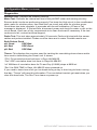
Preferences (1/2)
To access the delays menu: Press MENU / Configuration Preferences
Press / to adjust the following settings.
Preferences 1/2 pH
Lockout: 7.8
pH Lockout: is the pH reading at which IntelliChem will no longer dose sanitizer (Chlorine/
Bromine). Above pH of 7.8 it is generally understood that the ORP reading is suppressed
and therefore will not be used to administer additional sanitizer. Just bringing the pH level
down will raise the available chlorine and the effective ORP. At this trip point, an alarm
message will be shown on the screen and ORP doses will cease.
Range is 7.7 to 8.2, default is 7.8.
INTELLICHEM® Controller Installation and User’s Guide
20
Configuration Menu (Continued)
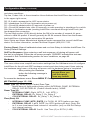
Preferences (2/2)
Preferences
2/2
Saturation Index
Alarm: +/- 0.5
Delay: 00:30:0
Saturation Index
Alarm: +/- 0.5: If the Saturation Index (SI) level is in the “Corrosive” or “Scaling” range, this
feature allows you to enter a Saturation Index (SI) alarm threshold value between +/- 0.1
to +/- 0.9 (+/- 5 default). Select “Disabled” to disable the Alarm feature.
Delay: The Alarm Delay feature sets the delay time before the SI Alarm (see above)
message is displayed. Enter the delay time from 00:15:00 to 24:00:00 (30 minutes default).
Note: Once the SI has passed the threshold for the delay period, an alarm message is
displayed showing the Saturation Index Alarm (along with other pH alarms) that includes
the value and description.
pH
>OK 7.44
-.72 Corrosive
ORP OK
730
Monitoring
pH
>OK 7.44
+.32 Scaling
ORP OK
730
Monitoring
These alarm messages are also displayed on the IntelliTouch, EasyTouch and SunTouch
control panel.
Dose Priority
To access the delays menu: Press MENU / Configuration Dose Priority
Press / to select option.
Dose Priority: pH Priority or Simultaneous.
Depending on how the IntelliChem chemical dosers are plumbed and how much water is
circulating in the system where the chemicals are injected into the water stream, it may
be preferred to only feed Chlorine when Acid is not feeding. This would be the pH Priority
setting.
•
Simultaneous allows both chemicals to feed at the same time - and
can be used when both feed systems are not liquid chemicals or the
injectors are separated by a safe distance in the water stream. DANGER:
Combining liquid acid and chlorine can result in the formation of
hazardous and explosive gas.
•
pH Priority will always feed acid first, and only during the acid mix time
or general monitoring period will the IntelliChem feed the liquid chlorine
sanitizer. If while feeding chlorine, the pH rises above setpoint, the ORP
dose will be stopped and allow acid to feed.
INTELLICHEM® Controller Installation and User’s Guide
21
Configuration Menu (Continued)
Diagnostics
Software Rev: Displays the software revision.
Meter Test: Performs an internal self-test of the pH/ORP meter and sensing circuitry.
Ensures both circuits are performing properly First tests the High circuit in the uncalibrated
state, waits for a button press, then tests the Low circuit and waits for a button press.
Once these two tests complete, it proceeds with the self-calibration. A Pass or Fail
message is displayed. If this test fails, disconnect power and check for water or dirt on the
circuit board. Use a can of dry compressed air to clean the board if necessary. If the test
continues to fail, contact technical support.
Probe Test: This test takes approximately 30 seconds. Perform this test with the sensor
cables and probes installed. Probes must be clean and in water. Possible results are :
Both Probes Good
pH: Good ORP:Bad
ORP:Good
pH: Bad
pH: Bad
ORP:Bad
Timers: This displays the counters used for tracking the cumulating dose volume and/or
time used in determining the Dose Limit. It shows:
“PCs” PH cumulative dose limit timer in Days HH:MM:SS
“Ocs” ORP cumulative dose limit timer in Days HH:MM:SS
“ml” Milliliters of cumulative dose for Ph and Orp (0-9999) stops at 9999 ml
“Run” the RUN TIME in Days, HH:MM:SS since powered up.
If you need to know how much you’ve dosed during a day, or how long its been running
that day, “Timers” will have this information. The cumulative times/ml get reset when you
clear the dose limits, The Run Time clears on power-up.
INTELLICHEM® Controller Installation and User’s Guide
22
Configuration Menu (Continued)
Diagnostics (Continued)
Chlorinator: This screen displays the current IntelliChlor (SCG) status, salt (ppm) levels
and error conditions. The hexadecimal status value is decoded and displayed in the
brackets on the bottom line; multiple error conditions are shown by sequencing through the
messages.
This display can be used to determine if the SCG is connected and responding to the
IntelliChem. If the IntelliChlor is connected, this display may show “Please wait 2-7 minutes
for ppm”. This indicates the IntelliChlor is responding to initial contact but until water flow
and sufficient salt level is reached, the IntelliChlor will not respond with further information
like salt ppm and status. Sometimes it is helpful to cycle power on the IntelliChlor and wait
10 minutes for the green lights before it will respond with ppm and status information; it
may not respond if the Salt or Cell lights are flashing red.
If the Configuration / Hardware / ORP Control / Doser Type is set to IntelliChlor, the
IntelliChem will control the IntelliChlor as it would a doser, actively turning it on (100%) for
chlorine demand, and off (0%) when the ORP reaches the desired set point.
For the Chlorinator to work when connected to an Automation controller like the
IntelliTouch, EasyTouch, or SunTouch, those units must be configured with the IntelliChlor
enabled. The displays is as follow:
-------------------------------------Chlorinator Info:
Salt: 4500 ppm
Status Code=00H
[OK-NO ERRORS ] V
-------------------------------------To get updated
ppm, cycle SCG
power and wait.
Press any button
-------------------------------------Possible messages are:
No Flow
Low Salt
Very Low Salt
High Current
Clean Cell
Low Voltage
Cold Water
INTELLICHEM® Controller Installation and User’s Guide
23
Configuration Menu (Continued)
Status Codes: This displays a complex series of values that indicate the real-time status
and alarm conditions.
Top line, Codes: HA= is the automation Home Address that IntelliChem has locked onto.
In the upper-right corner,
R0,1,2,4 which represents the UOC comm status.
R0 = standalone (no KA from Automation since power up)
R1 = Found KA packets within 30 seconds of power up
R2 = Found KA packets later, after 30 seconds, so was operating in standalone for a while
R4= Was in Automation mode (sending IntelliChlor commands through IntelliTouch) but
has dropped the connection.
The two-digit number (0-99) directly below the R# is the number of seconds it’s gone
without a valid KA packet. It should generally be 00-04 seconds. More than that means
that IntelliChem is missing the automation KA packets.
Note: Status and Alarm hexadecimal displayed codes represent the current IntelliChem
status. For further information, contact Technical Support (800) 831-7133.
Factory Reset: Clear all calibrated values and run Auto Setup to initialize IntelliChem. For
Factory Default Settings.
Self Test Sequence: Upon entering a self test sequence, all dosing will pause until
the test is completed. Follow the on-screen prompts. “PASSED” indicates the test was
successful. See Troubleshooting section for error conditions, on page 46.
Hardware
Most common hardware configurations can be selected by using the Auto Setup Wizard.
This menu allow more complex and custom settings.Use the Hardware menu to configure
IntelliChem for the pH and ORP hardware controls and dose being used. Upon entering
the hardware setup menu, all dosing will pause until the hardware setup is completed.
After pressing the Hardware
button the following message is
displayed.
Dosing will
resume when you
_exit this menu_
Press any button
To access the hardware menu: Press MENU Configuration Hardware
pH Control (page 1/2 - 2/2)
Doser Type 1/2: Select the pH Control Dose Type:
- IntelliChem pH feed method being used (INTERNAL PUMP, EXTERNAL
RELAY, CO2 EXT/RELAY (Carbon dioxide tanks), NONE.
Doser Type 2/2:
- INTERNAL PUMP: Right, MTR_R, Left, MTR_L
- EXTERNAL RELAY: Ex_Relay 1, Ex_Relay 2
- CO2 EXTERNAL RELAY: Ex_Relay 1, Ex_Relay 2
Flow (Rate) 2/2:
- INTERNAL PUMP (MTR_R/MTR_L): FLOW: 65 GPD (gallons per day).
- EXTERNAL RELAY 1 or 2: RATE: xxx GPD (gallons per day). Note: Set
to 0 to use time-based feed instead of volumetric (only on the Ext Relays
(not internal motors).
- CO2 EXTERNAL RELAY 1 or 2: Use Time (0) or SCFH (1-400).
INTELLICHEM® Controller Installation and User’s Guide
24
Configuration Menu (Continued)
ORP Control (page 1/2 - 2/2)
Doser Type 1/2: Select the ORP control hardware:
- IntelliChem ORP feed method being used (INTERNAL PUMP, EXTERNAL
RELAY, INTELLICHLOR® Salt Chlorine Generator (SCG), NONE.
Doser Type 2/2:
- INTERNAL PUMP: Right-Side (MTR_R), Left-Side (MTR_L)
- EXTERNAL RELAY: Ex_Relay 1, Ex_Relay 2
- INTELLICHLOR: All Models (IC20, IC40, IC60)
Flow (Rate) 2/2:
INTERNAL PUMP (MTR_R/MTR_L): FLOW: 65 GPD (gallons per day)
EXTERNAL RELAY 1 or 2: RATE: xxx GPD (gallons per day). Note: Set
to 0 to use time-based feed instead of volumetric (only on the Ext Relays
(not internal motors).
Hardware
settings must be chosen carefully. If both dosers are assigned to the same
internal pump or external relay, the program will display an error message upon exiting
the Hardware menu.
-
-
Alarm Output Select the following the IntelliChem® Controller alarm output information:
-
External alarm output: Ex_Relay1 or Ex_Relay2.
For an external alarm indicator, an unused relay may be selected to turn
on when the red Alarm LED on the front panel is turned on.
The alarm relay must be chosen carefully. If Ex_Relay1 or Ex_Relay2 is
used for a doser, it must not be used for an alarm output. Upon exiting the
Hardware menu, the program will check to be sure the same relay is not
used more than once. If a relay is assigned to more than one function, an
error message will be displayed.
error message:
-------------------------
Alarm Relay
conflicts with
Ext Doser Relay
Changed to Ex_R1
-------------------------- or
Changed to Ex_R2
or
Changed to N/A
INTELLICHEM® Controller Installation and User’s Guide
25
Auto Setup Sequence
Auto Setup
See page 6 for details.
SAT Index Overview
Saturation Index
The Saturation Index (SI), also called the Langelier Index, is a chemical equation or
formula used to diagnose the water balance in the pool. The Saturation Index formula
is SI = pH + TF + CF + AF - 12.1 (or 12.2 for salt pools). To calculate the Saturation
Index, you must first test the pool water for pH, temperature, calcium hardness, and
total alkalinity. Refer to a chart for assigned values for your temperature, hardness,
and alkalinity readings then add these to your pH value. Subtract 12.1 (or 12.2 for salt
pools), which is the constant value assigned to Total Dissolved Solids and a resultant number will be produced. A result between +/-0.3 indicates balanced water. Test
results not within these values require chemical adjustments to achieve balance. This
formula is more or less reliable but not guaranteed. In some cases, individual readings for pH, calcium, and Total-Alkalinity might be beyond normal recommendations,
however, combined within the formula can produce “balanced water.” The SI is useful
to pinpoint potential water balance problems.
To access the Sat Index menu:
Press MENU / Saturatn Index
Press / and /to adjust the Saturation Index values.
Menu
ORP Menu
Saturatn Index
Configuration
pH
pH: 6.0
77F
CH: 250
TA: 90
Temp:
SLT1000
CYA:18
Sat Index Menu
Note: The pH, Temp, and SLT are entered automatically as the numbers are available from
the measurement and automation system. Each time this display is entered, if available,
the current temperature is obtained from the INTELLITOUCH®, EASYTOUCH® Control
System), SLT is obtained from the INTELLICHLOR® Salt Chlorine Generator (SCG). But
these values can be changed on this screen for calculation purposes.
pH: Enter the current pH value.
Temperature: Enter the current temperature setting.
CH: Enter the current calcium hardness level.
SLT: Enter the current salt level or Total Dissolved Solids (TDS) level if no SCG is used.
TA: Enter the current total alkalinity value.
CYA: Enter the current cyanuric acid value.
SI: Displays the last calculated SI value (Corrosive/Scaling/Ideal). Note: If there is no
flow or Flow Delay is enabled, no SI value displayed.
pH: 6.0
77F
CH: 250
TA: 90
Temp:
SLT1000
CYA:18
pH: 6.0
77F
CH: 250
TA: 90
Temp:
SLT1000
CYA:18
INTELLICHEM® Controller Installation and User’s Guide
26
Sat Index Overview (Continued)
Recommended Pool Chemistry
pH range:
7.2 to 7.6
ORP range:
650 to 750
Alkanlinity:
80 to 120 ppm
200 - 500 ppm
Calcium Hardness:
Cyanuric Acid/Stablizer:
30-50 ppm
pH: Chlorine produced by the IntelliChlor SCG is close to Neutral pH. However, other
factors usually cause the pH of the pool water to rise. Therefore, the pH in a pool
chlorinated by IntelliChlor tends to stabilize at approximately 7.8. This is within APSP
standards. If the pool pH rises above 7.8, have a pool professional test to see if other
factors such as high Calcium Hardness or Total Alkalinity are the cause and then balance
accordingly.
Temperature: The pool water temperature can affect the saturation index value.
IntelliChem gets the temperature from the EasyTouch, IntelliTouch and SunTouch
automation control system. The automation control system must have the POOL or SPA
pump running to report the proper temperature to IntelliChem, otherwise IntelliChem will
use its own menu’s temperature value. To change the IntelliChem default temperature,
select Temp and use the Up/Down arrow to adjust the temperature.
pH Level Test: Test the pH level of your pool water with a reliable test method. If
necessary, adjust according to your pool professional’s recommendations. APSP’s
recommended ideal range for pH is 7.2 to 7.6. Note: Never use dry acid (sodium bisulfate)
to adjust pH in arid geographic areas with excessive evaporation and minimal dilution of
pool water with fresh water. A buildup of by-products can damage the IntelliChlor SCG
Calcium Hardness
Recommended range for calcium hardness is 200-500 ppm. Calcium Hardness levels
should be tested weekly. Calcium hardness is the calcium carbonate scale deposited
on pool surfaces. The test for Calcium Hardness is a measure of how “hard” or “soft”
the water is testing. “Hard” water can have high levels of calcium and magnesium. If
these levels are too high the water becomes saturated and will leave calcium carbonate scale deposits (a “white-ish,” crystallized rough spot) on any surface inside the
pool. If the levels are too low, the water becomes “soft” and will corrode surfaces inside the pool. Use TSP or Hydroquest 100 to lower Calcium Hardness levels that are
too high or add water to the pool which has a lower calcium hardness content. Levels
which are too low require the addition of calcium chloride.
Total Dissolved Solids (TDS): Adding salt to pool water will raise the TDS level.
While this does not adversely affect the pool water chemistry or clarity, the pool water
professional testing for TDS must be made aware salt has been added to the IntelliChlor
system. The individual performing the TDS test may then subtract the salinity level to arrive
at a TDS level that would be compatible to a TDS reading for a non-salt water pool.
Note: If a salt chlorine generator is being used for your pool, the salt level is the TDS
level of the pool.
INTELLICHEM® Controller Installation and User’s Guide
27
Sat Index Overview (Continued)
Total Alkalinity
APSP’s recommended ideal range for total alkalinity is 80 to 120 ppm for “gunite” and
concrete pools and 125-170 ppm for painted, vinyl, and fiberglass pools. Test levels
weekly and adjust according to your pool professional’s recommendations. Total Alkalinity can be described as a buffer that keeps pH in order. pH depends on the ability
of the total alkalinity in the water to withstand the changes in pH. If the total alkalinity
is too high, adding acid (similar to pH) lowers the level. Adding a base (e.g sodium
bicarbonate) when total alkalinity is low, raises the level. The level of total alkalinity in
the water is a measurement of all carbonates, bicarbonates, hydroxides, and other
alkaline substances found in the pool water.
Cyanuric Acid: Cyanuric acid is needed in outdoor pools to help to stabilize and maintain
proper levels of chlorine. 90% of unstabilized chlorine is destroyed by the UV radiation
from the sun. Cyanuric acid stabilizes chlorine in water from UV degradation. When using
the IntelliChlor SCG, the cyanuric acid level should be maintained between 30-50 ppm.
Optimum Pool Water Chemistry Conditions for Salt Water Pools
(using the IntelliChlor® Salt Chlorine Generator (SCG)
In accordance with the Association of Pool and Spa Professionals (APSP)
standards, it is recommended that the pool water chemistry conditions (see page
21) be maintained on an on going basis to help protect pool users, pool related
equipment and surfaces in and around the pool. These values are important to
maintaining the pool equipment in proper operating condition and preventing corrosion,
liming or other problems. The IntelliChlor (SCG) is warranted to operate properly only
if these conditions are met. For more information, refer to your local agency having
jurisdiction, NSPI (National Spa and Pool Institute), the CDC (Centers for Disease
Control), or the WHO (World Health Organization). Recommended pool water chemistry is
given below:
Free Chlorine: 2.0 - 4.0 ppm. Above 4.0 ppm may cause corrosion of metal components
Combined Chlorine (Chloramines): None (super chlorinate to remove all chloramines)
pH: 7.2 - 7.8 (USE MURIATIC ACID to lower pH and Soda Ash to raise pH.)
Cyanuric Acid: 30 - 50 ppm
Total Alkalinity: 80 - 120 ppm
Calcium Hardness: 200 - 400 ppm
TDS (includes salt): 3000 minium to 5700 to 6000 maximum ppm
Salt: 3000 - 4500 ppm (ideal 3400 ppm)
Metals (Copper, Iron, Manganese): None
Nitrates: None - Phosphates: Less than 125 ppb
Using the Langelier Saturation Index (LSI) to Diagnose Water
Balance
Use the Langelier Saturation Index (LSI) calculator to diagnose the water balance in
your pool. Water with a LSI of 1.0 is one unit above a balanced condition. Reducing the
factors by 1 unit will bring the water into equilibrium. To use the LSI calculator, refer to:
http://www.pentairpool.com/support/calculators/langelier/index.htm
INTELLICHEM® Controller Installation and User’s Guide
28
Sat Index Overview (Continued)
Calculating the Saturation Index
The saturation index is a formula that relates pH, calcium and alkalinity in the pool water.
A well balanced pool water will have a formula result range between -0.5 and 0.5 Outside
this range, the pool water is out of balance, potentially damaging pool equipment or
scaling the salt chlorine generator. The equation to calculate Si is:
SI = pH + CHF + AF + TF - TDSF
Saturation pH as
tested
Index
Calcium
Alkalinity
Hardness Factor Factor
Temperature TDS Factor
Factor
(12.1 non-salt,
12.2 salt pools)
Cyanuric acid in the form of cyanurate ions contribute to alkalinity. Thus, a correction must
be made to total alkalinity. We subtract 1/3 of the cyanuric acid level from the reading
obtained in the total alkalinity test.
Total Alkalinity - 1/3 Cyanuric Acid = Corrected Alkalinity
This correction can be considerable in established pools with high cyanuric acid levels; for
example, at 240 ppm cyanuric acid, the correction amounts to 80 ppm (240 ÷ 3 = 80).
Saturation Index Tables (as recommended by NSPF)
INTELLICHEM® Controller Installation and User’s Guide
29
INSTALLATION (INTELLICHEM® CONTROLLER AND FLOW CELL)
Installing the IntelliChem® Controller
Before installing the IntelliChem controller, read the following instructions.
1. IMPORTANT! If the equipment pad is below the water level of the pool,
please install a CHECK VALVE after the heater or use a Hartford Loop.
2. Identify new and existing equipment to be connected.
3. Decide if the sensors will be in a separate bypass line, or if the Flow cell
will be used. Caution: If the Flow Cell is being installed, the input
water maximum pressure is 25 PSI.
4. Determine the supply voltage, and wire the transformer wires as
needed (see page 31).
5. Determine if the control to the equipment uses the same voltage as the
supply voltage. All controlled equipment must be compatible.
6. Determine the water-tap points for the flow cell bypass inlet and outlet.
7. Install the Flow Cell away from direct sunlight and on a flat vertical
surface.
8. Switch the main house circuit breaker OFF. Connect the supply voltage to
the PUMP SIDE OF THE MAIN FILTER PUMP RELAY located in the load/
power center (see page 40 for the IntelliChem controller AC power wiring
diagram). This ensures that the IntelliChem controller will only dispense
chemicals when the filter pump is ON. Note: The IntelliChem controller
must be connected to a separate dedicated circuit GFCI.
9. If using a Flow Cell install the bypass now.
10. Connect the pH and ORP sensors.
11. Test the plumbing for leaks.
12. Switch on the IntelliChem controller for the first time as described below.
Risk of Electrical Shock or Electrocution!
IntelliChem controller must be installed by a licensed or certified
electrician or a qualified pool professional in accordance with
the current National Electrical Code and all applicable local
codes and ordinances. Improper installation will create an
electrical hazard which could result in death or serious injury to
pool users, installers or others due to electrical shock, and may
also cause damage to property.
Always disconnect the power to the IntelliChem controller enclosure at the circuit breaker before servicing the unit. Failure
to do so could result in death or serious injury to serviceman, pool users or others
due to electrical shock.
INTELLICHEM® Controller Installation and User’s Guide
30
Mounting IntelliChem® Controller Enclosure
Mount the IntelliChem controller enclosure as follows:
1. Select a location for mounting the IntelliChem® Controller enclosure with
the following required recommendations:
2. Install the IntelliChem controller enclosure at least 10 feet from the pool
or spa wall.
3. Supply power must be routed to the IntelliChem controller in accordance
with the applicable national and current local (NEC) codes (see page i).
4. The installation surface must be solid and vertical. Do not mount the
IntelliChem controller enclosure in a horizontal position.
5. Maintain adequate clearance for opening the enclosure.
6. The environment should be free of chemical fumes and excessive heat.
The maximum temperature it should not exceed is 110 ºF (50 C).
7. Mount as far as possible from sources of electrical interference.
8. Mount the enclosure on a flat surface.
9. Hold the enclosure against the mounting surface with a closed lid and
mark the location of the mounting brackets located on the sides of the
enclosure next to the wall. Prepare holes as necessary and secure
enclosure using the provided mounting screws.
10. Install a conduit into the controller enclosure.
Locate the chemical feed pumps and the chemical storage tanks in a safe and secure area. Never turn the chemical feed
pumps on when both flow cell valves are closed. Increased pressure may cause
the feed lines to blow off and spray full strength chemicals on anyone or anything
near the equipment. Securely fasten all electrical, water, and chemical lines.
Alarm
MOUNTING
HOLES
Menu
Select
INTELLICHEM
WATER CHEMISTRY
®
INTELLICHEM® Controller Installation and User’s Guide
MOUNTING
HOLES
31
Wiring the IntelliChem® Controller Transformer
DANGER!
RISK OF ELECTRICAL SHOCK OR ELECTROCUTION
Always disconnect AC power to IntelliChem controller at the
circuit breaker before servicing. Failure to do so could result in
death or serious injury to installer, serviceman, pool users, or
others due to electrical shock.
HIGH VOLTAGE WIRING
The high voltage wiring compartment is located inside the IntelliChem controller
enclosure. The IntelliChem controller can be connected either to 120VAC or 220-240
VAC. The IntelliChem controller should be wired to receive power from the filter pump
relay. Connect the AC power supply voltage to the PUMP SIDE OF THE MAIN FILTER
PUMP RELAY located in the load/power center (see page 40 for the IntelliChem
controller AC power wiring diagram). There is no ground/bonding terminal required
at this non-metallic enclosure. Follow manufactures instructions when installing and
testing of ground fault circuit breakers (GFCB) and interrupters (GFCI).
Connect input AC wires to the IntelliChem controller transformer wires as follows:
•
•
120 VAC: Connect one wire to the Brown/Black wires
connected together and one wire to the Blue/White wires
connected together.
220 - 240 VAC: Connect one wire to White wire and one wire to
Brown wire. The Black/Blue wires are connected together.
IntelliChem® Controller (Transformer Wiring)
INTELLICHEM® Controller Installation and User’s Guide
32
Connecting External Devices to IntelliChem Controller
External Devices such as pumps, CO2 devices and alarms can be connected to either
of the dry contact relays (EX_RELAY 1 and EX_RELAY 2). Relay contact ratings: 5
AMPS, 250VAC/30VDC located on the IntelliChem® Controller circuit board. See wiring
diagram below and “Plumbing the Flow Cell” on page 35.
BE SURE TO DISCONNECT ALL SUPPLY CONNECTIONS BEFORE SERVICING THE INTELLICHEM® CONTROLLER. AC Power may be
supplied to the relay terminals Ex_Relay1 and Ex_Relay2 from other sources.
Wiring external devices must be performed by a licensed certified electrician or a qualified pool professional in accordance with the
current National Electrical Code (NEC), NFPA 70 or the Canadian Electrical Code
(CEC), CSA C22.1. All applicable local installation codes and ordinances must
also be adhered to. Improper installation will create an electrical hazard which
could result in death or serious injury to pool users, installers or others due to
electrical shock, and may also cause damage to property.
External Devices:
EX_RELAY 1 and
EX_RELAY 2,
contact ratings:
5 AMPS,
250 VAC/30 VDC
External Device Wiring Diagram
INTELLICHEM® Controller Installation and User’s Guide
33
Installing the Flow Cell and pH/ORP Sensors
pH and ORP sensors are shipped with a protective cap covering the
electrode tip of the probes to protect the sensing element. DO NOT
MIX THESE CAPS - Solutions will destroy the other type of probe. Sensors should
be kept in the protective cap until ready for installation, if the sponge in the boot
becomes dry, wet it with pool water. Before using the sensor remove the cap.
Mounting the Flow Cell
Remove Flow Cell from shipping carton and select a suitable location for the flow cell
within two (2) feet of the IntelliChem® Controller.
Note: The 3/8” flexible tubing that is required to connect the flow cell to the rest of the
system is included with IntelliChem controller kit.
Mounting holes
Flow
Switch
Magnet
Flanged
end down
Installing the pH and ORP Sensors (Read This First)
Install the pH and ORP sensors as follows: For IntelliChem® Controller Plumbing
Installation Diagram, see page 37.
1. Sensors wires will connect to within 10 feet.
2. Water leaks will cause damage! Mount where water does not leak and
damage other components.
3. Mount flow cell vertically with provided screws.
4. Securely fasten all electrical, water and chemical lines.
5. Locate chemical feed pumps and chemical storage tanks in a safe and
secure area.
6. Maximum operating pressure = 25 psi.
7. Extreme pressure variances may affect readings and can cause damage
to the sensors.
8. Avoid installing the outlet before the main pump as the vacuum may
damage the chemical sensors.
Note: Do not over tighten fittings on flow cell top.
INTELLICHEM® Controller Installation and User’s Guide
34
Installing the pH and ORP Sensors
To install the Flow Cell pH and ORP sensors:
1.
Keep pH and ORP sensors wet at all times, install the sensors into the
flow cell. Hand-tighten only and save caps for future use (DO NOT MIX
THESE CAPS), fill flow cell with water. The sensors have O-Rings and
don’t require threaded sealing tape.
• Do not rub hard on the glass element in the sensor or use
sand paper or other polishing material to clean.
•
Handle electrode carefully.
•
Sensors contain external and internal glass elements.
•
Do not drop or otherwise subject the sensor to vibration,
physical impact.
To avoid permenant damage of sensors or flow
cell, do not use during freezing conditions.
•
Leave excess wire outside the controller enclosure. If the
cable is longer than needed, it should be coiled neatly and
attached under the controller enclosure.
•
DO NOT CUT THE SENSOR WIRES. Do not stuff excess
wire inside the controller as this may cause excess strain on
sensor and relay connections.
pH Sensor
INTELLICHEM® Controller Installation and User’s Guide
ORP Sensor
35
Plumbing the Flow Cell
Be sure to have a licensed plumber perform all plumbing;
this is important, as they will be familiar with all of the
codes in the local area.
To connect the Flow Cell to the system plumbing: See page 37 for plumbing diagram.
1. At the equipment pad, switch off the filter pump and release the pressure
from the system by opening the valve on top of the filter.
WARNING CHEMICAL BURN HAZARD: Make sure all pumps are
switched off at the main circuit breakers at the house before drilling
into any pipes. Securely fasten all electrical, water and chemical
lines. Locate chemical feed pumps and chemical storage tanks in a
safe and secure area.
2. Close all valves to prevent flooding.
3. Attach the IN and OUT tubes to the Flow Cell Inlet and Outlet
(see Tubing Installation Diagram shown below).
4. Run the end of the IN tube to the chosen pressure line. Choose a location
that provides enough space to drill and to tighten the clamp (must be after
the filter, but before the heater). Be sure the tube is not pinched or kinked.
Mark a spot on the pipe.
5. Locate where the water will be supplied from and returned for each flow
cell. The most common location for the water inlet to the flow cell is
AFTER the main filter and BEFORE the heater. See page 37.
6. Drill a 3/8” hole for the flexible tubing fitting on the mark and immediately
place the fitting into the pipe. Align pipe clamp with the fitting and tighten
the pipe clamp.
7. Run the end of the OUT tube (with the pipe clamp) to the chosen return
line. Choose a location that provides enough space to drill and to tighten
the clamp (must be after the heater - see page 37). Be sure the tube is
not pinched or kinked. Mark a spot on the return line pipe.
8. Drill a 3/8” hole for the flexible tubing fitting on the mark and immediately
place the fitting into the pipe. Align pipe clamp with the fitting and tighten
the pipe clamp.
9. Open any closed system valves. Close the filter valve and turn on the
circulation system. Check that the system is working properly.
Tubing
Pipe
Clamp
3/8"
Drill
Pipe
IntelliChem® Controller Tubing Installation Diagram
INTELLICHEM® Controller Installation and User’s Guide
36
Plumbing the Flow Cell (Continued)
Do not inject acid directly in to the flow cell. Injecting acid in
this way will result in incorrect reading which may damage the
existing pool equipment.
10. Locate the chemical injection points.
11. Prepare and install the chemical injector fittings.
12. Install the chemical storage containers.
13. Turn ON the main circulation pump.
14. Check for leaks and verify the flow sensor indicates flow.
Flow Cell Inlet and Exit Lines
1. It is essential that the supply line be at a higher pressure than the
discharge line so the water will flow through the cell at a steady rate in
the right direction.
2. Inlet should be installed after filter and before heater. Note: Plumb the
INLET before the solar valve.
3. Exit should be installed after heater and as far away from any equipment
as possible.
Make sure all pumps are OFF before drilling into pipes. Never
switch ON chemical feed pumps without the pool filter pump
also running.
The flow switch is a dry contact only (no current). Use with any
other brand of flow switch voids WARRANTY
and UL listing.
INTELLICHEM® Controller Installation and User’s Guide
Tubing
Fitting
Outlet
Flow Switch
pH
Sensor
FILTER
Inlet
HEATER
Filter
®
INTELLICHEM
WATER CHEMISTRY
CHLORINE
P/N 521895 (see page 32)
ACID
Chlorine
Pump
HANDTIGHTEN
TIGHTEN FITTINGS
HAND
FITTINGSONLY:
ONLY:
USING A WRENCH TO TIGHTEN WILL CRACK FITTINGS
USING A WRENCH TO TIGHTEN WILL CRACK FITTINGS
Figure 2: IntelliChem® Controller Plumbing Installation
Figure 2: IntelliChem® Controller Plumbing Installation
Sample
Valve
ORP
Sensor
Acid Injection
pump
IntelliChem® Controller
Pump
CO2
Tank
Water
Flow
CO2 Kit
P/N714000070
Pump
External pumps option:
1 pump (acid feed)
2 pump
(acid/chlorine feed)
Chlorine
Acid
37
IntelliChem® Controller Installation Plumbing Diagram
IntelliChem® Controller Installation Plumbing Diagram
37
INTELLICHEM® Controller Installation and User’s Guide
38
Connecting the Sensors Wires to IntelliChem® Controller Circuit Board
The Flow Switch is a Dry Contact Only (No Current). This Flow
Switch should only be used with the IntelliChem® Controller. Use
of this Flow Switch with any other brand of controller will void the
warranty and UL listing.
1. Route the Flow Cell switch wires into the IntelliChem controller enclosure
through the strain relief and connect the wires to J6 Sensor terminal
connector on the IntelliChem controller circuit board. Connect the
BLACK wire to the GND screw terminal and the RED wire to the
FLOW screw terminal.
2. Route the pH and ORP sensor wires into the IntelliChem controller
enclosure through the strain relief and connect to J6 Sensor terminal
connector on the IntelliChem controller circuit board. The sensor wires are
labeled. PLUS AND MINUS POLARITY MUST BE OBSERVED.
pH sensor wire: Connect the GREEN to the pH - screw terminal and the
CLEAR wire to the pH + screw terminal.
ORP sensor wire: Connect the GREEN to the ORP - screw terminal and
the CLEAR wire to the ORP + screw terminal.
Figure 2: IntelliChem® Controller J6/J7 Circuit Board Wiring
3. Turn the main pump on and open the valves to test for leaks and the free
movement of magnet. Magnet must be all the way up in order to close the
flow switch. 1/4 GPM will push the magnet all the way up.
Make sure that all pumps are off before drilling into any
pipe.
Never turn chemical feed pumps on when either flow cell
valve is closed.
INTELLICHEM® Controller Installation and User’s Guide
39
CONNECTING TO AN AUTOMATION CONTROL SYSTEM
Wiring IntelliChem® Controller AC Power to Filter Pump Relay
IntelliChem AC Power Wiring Instructions: When using IntelliChem as
a stand alone device (with a time clock) or with an IntelliChlor salt chlorine
generator, IntelliChem MUST BE CONNECTED TO THE LOAD SIDE OF THE
FILTER PUMP RELAY located in the load/power center (see page 40 for
IntelliChem AC power wiring diagram). This ensures that IntelliChem will only
dispense chemicals when the filter pump is ON.
For IntelliTouch®, EasyTouch® or SunTouch® control system using an IntelliFlo®
pump (or 2-speed pump) and an IntelliChlor® (SCG), the IntelliChlor controller
AC power center wires must also be connected to the LOAD SIDE OF THE
MAIN FILTER PUMP RELAY located in the load/power center (see page 40 for
diagram). This ensures that IntelliChem controller and IntelliChlor SCG only
produce chlorine when the main filter pump is on.
The following wiring diagram (see next page) shows the IntelliChem controller AC power
wiring and COM port connections to the EasyTouch, IntelliTouch and SunTouch control
system.
INTELLICHEM® Controller Installation and User’s Guide
40
IntelliChem® Controller AC Power and COM port (RS-485) Wiring Diagram
Note: For more information about operating
automation pool controllers, refer to the following
manuals:
- IntelliTouch® Control System User’s Guide
(P/N 521075)
- EasyTouch® Control System User’s Guide
(P/N 521044)
INTELLICHEM® Controller Installation and User’s Guide
41
Wiring the IntelliChem Controller AC Power to Automation Filter Pump Relay
PLease read the following information before starting!
IntelliChem controller AC Power Wiring Instructions: When using
the IntelliChem controller as a stand alone device (with a time clock) or
with an IntelliChlor salt chlorine generator, IntelliChem controller MUST BE
CONNECTED TO THE LOAD SIDE OF THE MAIN FILTER PUMP RELAY located
in the load/power center (see page 40 for the IntelliChem controller AC power
wiring diagram). This ensures that the IntelliChem controller will only dispense
chemicals when the filter pump is ON. Note: For IntelliTouch®, EasyTouch®
or SunTouch® control system using an IntelliFlo® Pump (or 2-speed pump)
and an IntelliChlor (SCG), the IntelliChlor controller AC power center wires
must also be connected to the LOAD SIDE OF THE MAIN FILTER PUMP RELAY
located in the load/power center (see page 40 for diagram). This ensures that
the IntelliChem controller and IntelliChlor SCG only produce chlorine when the
main filter pump is on.
To connect IntelliChem controller AC power wires to EasyTouch, IntelliTouch
and SunTouch control system filter pump relay (see diagram on previous page).
DANGER!
RISK OF ELECTRICAL SHOCK OR ELECTROCUTION
Always disconnect AC power to EasyTouch, IntelliTouch and
SunTouch control system load/power center at the circuit breaker
before servicing, or removing the HIGH VOLTAGE FRONT
PANEL. Failure to do so could result in death or serious injury to
1. IntelliChem Controller AC power: Run the IntelliChem controller AC
power wires to the EasyTouch, IntelliTouch or SunTouch control system
enclosure.
2. EasyTouch or IntelliTouch Control System Load Center: Unlatch the
enclosure door spring latch, and open the door.
3. Discharge Electrostatic energy before removing the cover by first
touching the metal part of the enclosure.
4. Loosen the two (2) retaining screws from the HIGH VOLTAGE FRONT
PANEL. Remove the panel from the enclosure.
5. Connect the IntelliChem controller AC power cord wires to the LOAD/
PUMP SIDE of the main filter pump relay (see wiring diagram on page
40).
6. When the connection is completed: EasyTouch and IntelliTouch Control
System: Close the control panel and secure it with the two (2) retaining
screws. SunTouch Control System: Close the front control panel and
secure with the retaining screw.
INTELLICHEM® Controller Installation and User’s Guide
42
Retaining
screws
High Voltage
Front Panel
Route IntelliChem® Controller AC
power into opening under enclosure
CONNECT INTELLICHEM CONTROLLER
AC POWER TO FILTER PUMP RELAY
CONNECT INTELLICHEM CONTROLLER
AC POWER TO FILTER PUMP RELAY
Power Center
(with SCG option)
Load Center (with SCG option)
INTELLICHEM® Controller Installation and User’s Guide
IntelliChlor® Salt Chlorine
Generator(SCG) Transformer
43
Connecting IntelliChem® Controller RS-485 Communication Cable
to the Control System Circuit Board
To connect the IntelliChem controller COM Port Cable to EasyTouch®,
IntelliTouch® and SunTouch® Control System COM port (see page 40):
1. IntelliChem controller RS-485 cable: Strip back the cable conductors
¼ in. Insert the wires into the connector screw terminals. Make sure to
match the color coding of the wires; YELLOW = +DATA, GREEN = -DATA
and BLACK = GND. (Red wire is not connected). Secure the wires with
the screws.
2. Run an RS-485 cable from the IntelliChem controller enclosure to the
EasyTouch, IntelliTouch or SunTouch control systems enclosure.
3. Unlatch the load center/power center enclosure door spring latch, and
open the door.
4. WARNING! Switch AC power OFF to load/power center before
installation (see note on page 41) EasyTouch or IntelliTouch control
system load center: Loosen the two (2) retaining screws from the control
panel. (a) Lower down the control panel on its hinges to access the
motherboard located behind the control panel. (b) Route the IntelliChem
controller RS-485 cable up through the low voltage raceway in the load
center to the motherboard.
SunTouch Control System Power Center: Route the conductor cable up
through the lower grommet opening into the enclosure.
5. Strip back the IntelliChem controller cable conductors ¼ in. Insert the
wires into the COM port connector screw terminals on the circuit board:
(EasyTouch J20, IntelliTouch J7/8, SunTouch J11). Make sure to match
the color coding of the wires; YELLOW = +DATA, GREEN = -DATA and
BLACK = GND. (Red wire is not connected). Secure the wires with the
screws.
6. When the connection is completed: EasyTouch and IntelliTouch Contol
System: Close the control panel and secure it with the two (2) retaining
screws. SunTouch Control System: Close the front control panel and
secure with the retaining screw.
Setting Up EasyTouch, IntelliTouch & SunTouch Control System
IntelliTouch Control System
The following describes how to setup the IntelliChem controller from the IntelliTouch
control system control panel. From the IntelliTouch control system control panel you can
adjust the pH and ORP set point values, view the IntelliChem controller status and monitor
your pool water condition using the Saturation Index. To access the IntelliChem controller
the screens, from the IntelliTouch control system indoor control panel or the wireless
MobileTouch® Controller control panel:
Getting There
MENU SETUP
EQUIPMENT INTELLICHEM
PH/ORP Values: The pH and ORP values are displayed next to the set point settings.
pH Set: Displays the current pH set point value. The adjustable range is from 7.2 to 7.6 in
increments of 0.1. The default pH set point value is 7.5. To adjust the pH set point, press
the button next to pH Set.
INTELLICHEM® Controller Installation and User’s Guide
44
ORP Set: Displays the current ORP set point value.
The adjustable range is from 650 to 800 in increments
of 10. The default ORP set point value is 700. The
ORP set point is the value that IntelliChem will try to
achieve based on the active sanitizer. To adjust the
ORP set point, press the button next to ORP Set.
STATUS: Displays the current communication link
between IntelliTouch and IntelliChem via the RS485 cable. IChem Comm Error: Check the RS-485
communication cable is connected to the COM port
on the IntelliTouch Personality circuit board.
USING SCG: “USING SCG” displays if the IntelliChlor
salt chlorine generator is enabled. The SCG is enabled and disabled from the MENU >
SETUP > EQUIPMENT > CHLORINATOR screen.
Note: IntelliChem must also be set up to use the
IntelliChlor SCG either with the AUTO SETUP
Setup Wizard (page 6) or the Configuration/
Hardware/ORP Control/Doser Type (page 24).
DISABLE/ENABLE INTELLICHEM: To disable
IntelliChem, press the button under DISABLE
ICHEM. To enable IntelliChem, press the button next
to INTELLICHEM. On the next screen press button
next to NO and select YES. Press SAVE to save the
setting and return to the Equipment screen.
Saturation Index/Menu: To access the Saturation
Index screen, press the button next to SATURATION
INDEX/MENU. The current Saturation Index value,
water condition, water temperature and salt level
are displayed. Press the button next the following
selections to adjust the levels/values: Calcium
Hardness: Recommended range is 200-400 ppm.
Levels should be tested weekly. Cyanuric Acid:
Stabilizes chlorine in water from UV degradation.
When using the IntelliChlor SCG, cyanuric acid
level should be maintained between 30-50 ppm.
Total Alkalinity: APSP’s recommended ideal range for is 80 to 120 ppm for “gunite” and
concrete pools and 125-170 ppm for painted, vinyl, and fiberglass pools. Test levels weekly
and adjust according to your pool professional’s recommendations.
Saturation Index: The saturation Index displays IDEAL (Optimum levels), CORROSIVE
or SCALING. The following are recommended pool chemistry Saturation Index levels: pH
range: 7.2 to 7.6 ORP range: 650 to 800. Alkanlinity: 80 to 120 ppm. Calcium
Hardness: 200 - 500 ppm. Cyanuric Acid/Stabilizer: 30-50 ppm.
Note: See page 28 for information the online Langelier Saturation Index (LSI) Calculator
to diagnose the water balance in your pool.
INTELLICHEM® Controller Installation and User’s Guide
45
Setting Up IntelliChem® Controller with EasyTouch Control System
EasyTouch® Control System
The following describes how to setup the IntelliChem® Controller from the EasyTouch
Control Systems control panel. From the EasyTouch control system control panel you can
adjust the pH and ORP set point values, view the IntelliChem controller status and monitor
your pool water condition using the Saturation Index. To access the IntelliChem screens,
from the EasyTouch Indoor Control Panel or the EasyTouch wireless control panel: Press
MENU > SETTINGS > INTELLICHEM
PH/ORP Values: Press the Right button to access the
Clock
pH and ORP set point values screen. The pH and ORP
IntelliFlo
sensor reading VALues are shown only if adequate flow is
IntelliChlor
IntelliChem
sensed by the flow switch and the delay has been satisfied.
otherwise displays NA (not available) Use the Up/Down
IntelliChem
button to adjust the pH set point value. Press the Right
PH/ORP Values
button again to set the ORP set point value. Press MENU
Status
to save and return to the previous screen.
Sat Index
pH Set Point: Displays the current pH set point value. The
pH
VAL 7.0
adjustable range is from 7.2 to 7.6 in increments of 0.1. The
pH
SET: 7.5
default pH set point value is 7.5.
ORP VAL: 650
ORP Set Point: Displays the current ORP set point
ORP SET: 750
value. Use the Up/Down button to adjust the ORP set
IntelliChem
point value. The adjustable range is from 650 to 800 in
PH/ORP Values
increments of 10. The default ORP set point value is 700
Status
The ORP set point is the value that IntelliChem will try to
Sat Index
achieve.
pHLvl:
STATUS: Displays the current communication link between
ORP Lvl: SCG EasyTouch and IntelliChem via the RS-485 cable. IChem
IntelliChem: ON
Comm Error: Check the RS-485 cable is connected to the
ORP Dosage Limit
COM port on the EasyTouch circuit board. If “IntelliChem:
--Disabled--” is displayed enabled IntelliChem from the
IntelliChem
PH/ORP Values
automation system (see “Using SCG” on page 44). Other
Status
alarm messages are shown on page 48
Sat
Index
pH: 7.5 TMP: 91
CH: 250 SLT: 4250
TA: 100 CYA: 30
SI= +0.04 IDEAL
Level Gauge indicator: Press the Up/Down button to “fill”
the gauge icon so that it visually represents the same amount
of acid available in the container. Press Up/Down button six
(6) times to fill the gauge (three times to half fill the gauge).
Six horizontal bars represent chlorine (or bromine) supply
is full. One bar indicates the supply is nearly empty. Press
MENU twice to exit and update the values.
Note: IntelliChem must also be set up to use the IntelliChlor SCG either with the AUTO
SETUP Wizard (page 6) or the Configuration/Hardware/ORP Control/Doser Type (page 24).
Sat Index: To access the Sat Index settings, press the Up/Down button then press the Right
button. Use the Up/Down button to adjust the levels/values for: CH (calcium hardness),
SLT (Salt Content in water or Total Dissolved Solids if no salt is present), TA (total
alkalinity), CYA (cyanuric acid) and TMP (current temperature). Note: See table below for
ideal Saturation Index levels. SI: The saturation Index is displayed. IDEAL: Optimum levels.
CORROSIVE or SCALING: Press the Menu button twicw to exit and update the values. Return
to this menu for updated SI calculations. screen. Note: See page 28 for information the online
Langelier Saturation Index (LSI) Calculator to diagnose the water balance in your pool.
INTELLICHEM® Controller Installation and User’s Guide
46
Setting up IntelliChem® Controller with SunTouch Control System
SunTouch Automation Control System
The following describes how to view the current IntelliChem pH and ORP levels
from the SunTouch control panel. To access the IntelliChem screens Press MENU >
DIAGNOSTICS > INTELLICHEM
Displays the current pH and ORP levels. The IntelliChem
IntelliChem
controller is connected to the SunTouch control system
pH: 7.65 ORP:832
via the RS-485 cable. The RS-485 communication cable
is connected to the COM port on the SunTouch® Control
System circuit board.
TROUBLESHOOTING
General Troubleshooting Guide (also see Help Guide on page 47)
1. Run Meter Self-Test (see Configuration menu)
Run Probe-Open Test (see Configuration menu)
Clear pH and ORP Tweaks (see Configuration menu)
Clean Sensors (see Maintenance section)
Check chemicals and feed system
Take sample of pool water for analysis of CYA, alkalinity, check saturation
index, Balance water
7. Replace Sensors
8. Repeat above steps
2.
3.
4.
5.
6. General Guidelines - pH or ORP not able to reach setpoint
This may be a common issue that can easily be resolved by increasing the amount of
chemical dispensed each day. If the pH Sensitivity is set to “Low” (the default), IntelliChem
will only administer the full dose at 0.5 from setpoint. If it seems to be stuck 0.3 from
setpoint, you’re only getting 3/5 of the programmed dose. Change the Sensitivity to “High”
and you’ll get the full dose at 0.2 pH or greater from setpoint. Or, turn pH Sensitivity OFF only turn it on if you’re overshooting the setpoint.
Increasing the dose would essentially do the same thing. Increase the dosage as well as
the dose-limit and reduce the mix time so you still get all 8 doses in the filter run time.
Diagnostics Self Test and Error codes
The overall functionality of the IntelliChem can be verified by running the self test. Access
this feature in the Configuration/Diagnostic menu. The test verify the LCD display, front
panel LED indicators, push buttons, flow switch input, doser motors, relays, the RS-485
communication, and the meter.
Warning! This test will turn on the doser, so be sure that the tubing is installed in a
safe manner so that the chemicals will be safely contained.
Error Codes (Self Test Status: Fail)
01H : LCD
02H : Backlight
04H : LEDs
08H : Buttons
10H : Flow Switch
20H : Outputs
40H : Loopback 485
80H : Meter
INTELLICHEM® Controller Installation and User’s Guide
47
Help Guide
INTELLICHEM® Controller Installation and User’s Guide
48
Alarm Messages and Troubleshooting Tips
The IntelliChem is continually monitoring its own condition and that of the water chemistry.
The following is a list of alarms and most likely causes. This should give you a good
starting place for troubleshooting and resolving the alarm.
Troubleshooting the alarm messages
** Displayed in various places on the main screen
INTELLICHEM® Controller Installation and User’s Guide
49
Troubleshooting the alarm messages
Flashing pH/ORP
tank/hourglass symbol
Check pH Tank
Check ORP Tank
ORP LOW
ORP HIGH
ORP Is Too Low
Check overall water chemistry using the Saturation Index calculator or
have water tested by a professional pool service person or dealer. Also,
check that the dose dispensing device is operating properly and that
your supply tank is full.
ORP Is To High
Overshooting ORP may simply be a result of Cyanuric acid in the pool
which suppresses the ORP during the sunlight hours and releases
chlorine at night. It may also be that dose size is set too high with
insufficient mix time. Turning ORP Sensitivity to “Low” may help reduce
overshooting.
PH Is Too Low
pH Reading Too Low
pH HIGH
PH Is Too High
pH Reading Too High
NO FLOW DETECTED
Increase filter time and increase dose size. This may be the result of the
ORP Sensitivity setting. If the sensitivity is set to “Low”, you may not
have a sufficiently sized dose to reach the setpoint. Try turning
Sensitivity to “High” or “Off”.
ORP Reading Too Low
ORP Reading Too High
pH LOW
Refill the chemical supply container and set the gauge to the appropriate
corresponding level. This alarm indicates level is low and should be
refilled. If non-fluid supply sources are used, like CO2 and SCG, you can
set a reminder in the pH/ORP Supplies 2/2 menu that will trigger this
alarm as a reminder to change CO2 canisters or clean the SCG plates.
The reminder is reset either in the Supplies 2/2 menu or the pH/ORP
Settings button.
No Flow
Check pump, flow cell, filter,
and valves.
Overshooting pH may be due to the dose size being set too high with
insufficient mix time. Turning pH S ensitivity to “Low” may help reduce
overshooting. Test overall water chemistry using the Saturation Index
calculator. Low Total Alkalinity may contribute to rapid pH swings and
make controlling water nearly impossible. Consult your pool
professional.
Check overall water chemistry using the Saturation Index calculator or
have water tested by a professional pool service person or dealer. Also,
check that the dose dispensing device is operating properly and that
your supply tank is full.
Increase filter time and increase dose size. This may be the result of the
pH Sensitivity setting. If the sensitivity is set to “Low”, you may not have
a sufficiently sized dose to reach the setpoint. Try turning Sensitivity to
“High” or “Off”.
Ensure the pool pump is turned on, that valves are properly positioned,
and that sufficient water is being directed to the flow cell. Make sure the
magnet is properly contained in the flow tube and that the detector is
wired properly to the Flow switch terminal block. The flow switch should
be closed (shorted) to indicate flow.
Warning: This is a Safety Device. Do not operate the IntelliChem with
the flow switch bypassed. Water flow must be present to ensure
chemicals are mixed adequately to avoid dangerous gasses and high
concentrations of chemicals near people or pool equipment.
Awaiting FLOW DELAY
Flow Delay
This is not an alarm, only a message indicating that water chemistry
control will commence after this count-down timer expires. To allow pool
water to stabilize and time for chemicals to activate, a minimum of 15
minutes is required to get accurate readings. The Flow Delay is set in
the Configuration/Delays menu. It is the combination of the Power- On
and Flow-Switch delay settings. As a convenience for the pool service
person, you may bypass the delay by holding the Up Arrow button for 3
seconds. Please give time for the water to stabilize before expecting
proper operation of the equipment.
pH has priority
PH Priority
This is not an alarm but a message that pH is feeding (acid) and that
ORP (chlorine) is on hold until the acid feed is finished. This is enabled
in the Configuration/Dose Priority menu on systems where the acid and
chlorine may be injecting near the same point in the plumbing and the
installer has decided, for safety reasons, to only feed one chemical at a
time.
** Displayed in various places on the main screen
INTELLICHEM® Controller Installation and User’s Guide
50
** Displayed in various places on the main screen
Cross Reference
INTELLICHEM® Controller Installation and User’s Guide
51
Tweaking pH (Calibrating Sensor)
Measure the pH using a standard test kit by taking several readings and averaging the
results. To Tweak the pH sensor see page 12.
Tweaking ORP (Calibrating Sensor)
Always make sure the pH is at the set point before calibrating ORP.
Always control at PPM levels greater than 1.0 PPM when using ORP
sensors.
IMPORTANT: For best results the ORP should be at the ORP set point when calibrating. For best
results the PPM should be at the desired level when calibrating ORP. To Tweak the ORP sensor
see page 15.
IntelliChem Specifications
RATINGS:
Input Voltage: 120 VAC / 220-240 VAC 50/60 Hz
200 mA / 100 mA or 0.2 A / 0.1 A
Relay Rating: Dry Contact 5 A, 120 VAC / 30 VDC
Temperature:Min./Max. Operating Temperature 30° - 110° F
Sensor Range:
pH 4.0 - 9.99 - ORP 0 - 999mV
Flow Open or Closed
MAINTENANCE
Winterizing: The Flow Cell sensors must be protected from freezing conditions. If the pool
is winterized, plan to remove and store the sensors (as described above) as part of the
normal pool winterizing process. The Flow Cell and related plumbing must be drained as
well.
Water Chemistry
Always test water chemistry with a quality manual test kit. Therefore, it may be preferable
to calibrate pH using commercially available reference solutions. If required, use the
IntelliChem Tweak pH feature to periodically adjust the pH reading (see above and page
12). It’s important to note that changes in pH, cyanuric acid concentration, total dissolved
solids, and use of additional or alternative sanitizers will all affect the primary sanitizer
residual level relative to ORP. Maintain total alkalinity on regular basis to ensure pH
stability. To maintain a consistent sanitizer residual in parts per million (ppm), periodically
adjust the ORP level.
Sensor Maintenance: The Flow Cell sensors must be clean and free from oil, chemical
deposits and contamination to function properly. After saturation in pool or spa water, the
sensors may need to be cleaned on a weekly or monthly basis depending on bather load
and other pool specific characteristics. Slow response, increased need to calibrate pH,
and inconsistent readings are indications that the probes are in need of cleaning.
INTELLICHEM® Controller Installation and User’s Guide
52
MAINTENANCE (Continued)
Cleaning the Flow Cell Sensors: To clean the ORP and pH sensors, turn off the AC
source power to IntelliChem at the GFCI switch. Disconnect the probe connectors from
the Flow Cell, unscrew the probe and carefully remove them from the Flow Cell. Clean the
reference junction (the white ring at the bottom of the probe body) with a soft toothbrush. A
household liquid dish washing detergent may also be used to remove any oil. Rinse with
fresh water and reinstall probes. If properly cleaned probes continue to provide unstable
readings or require excessive calibration, the probes should be replaced. Probe exposed
to atmospheric conditions will cause the probe tips to dry out. Store the sensors with the
included plastic sensors storage caps if removed from the Flow Cell for more than one
hour. If the storage caps have been misplaced, store the probes individually in small glass
or plastic containers with clean water covering the sensor tips. Store sensors in a location
that will not be subjected to freezing temperatures.
Sensor Care
Contamination of the sensing elements often results in slow response and inaccurate
readings. Clean the elements by the following procedures:
pH and ORP Sensors
1. Wash electrode tip in a liquid detergent and water. Carefully use a soft
bristled toothbrush to wash the electrode tip and white sensing ring.
2. Rinse after cleaning. To reinstall the flow cell (see page 33). Hand tighten
to sensors to secure in place.
3. Make sure the O-ring is installed on sensor.
4. If the cable is longer than needed, it should be coiled neatly and attached
under the enclosure.
pH Sensors Only
5. Attempt to clean the sensor with liquid detergent first.
6. If this is not successful, swirl the tip of the sensor in a 5 parts water and 1
part muriatic acid solution for 10 - 20 seconds.
7. Rinse again and reinstall.
WARNING Do not rub hard the glass element in the sensor or use sand paper or other polishing material to clean. HANDLE ELECTRODE CAREFULLY Sensors contain external and internal
glass elements. Do not drop or otherwise subject the sensor to vibration, physical impact, or
freezing conditions. ANY TYPE OF BREAKAGE IS NOT COVERED UNDER WARRANTY.
pH and ORP Sensors: pH electrodes sense the acidity of the water and work with
any acid or base. The blue bands on the cables identify the pH sensors. The red bands
on the cables identify ORP sensors. Each sensor is also identified on the sensor
body. ORP electrodes are used to monitor the Oxidation Reduction Potential (ORP is
sanitization quality of the water) of a given solution. The sensing element of the ORP
electrode is made of a precious metal such as platinum or gold.
Sensors: IntelliChem measures the following sensor measurements with the listed
characteristics:
pH Range: 4.00 to 9.99
ORP Range: 0 to 999 mV
Flow Switch: This input measures if a switch is open or closed. Open is no water flow.
A closed switch indicates flow.
INTELLICHEM® Controller Installation and User’s Guide
53
Motor Pump Head Yearly Replacement
IMPORTANT! Replace the IntelliChem pump head (P/N 521384Z)
once a season (yearly).
Pump Head Replacement (for single or multiple pumps)
Disconnect AC power to IntelliChem® Controller enclosure at the circuit breaker before servicing. Failure to do so could result in
death or serious injury to serviceman, pool users or others due to electrical shock.
1. STOP THE MAIN POOL FILTERPUMP.
2. First loosen the Jaco fitting on the OUTLET tube. Carefully disconnect the
tube. Keep the tube pointed upward to keep the chemical from spilling out
the top of the tube.
3. Connect the tube to the OUTLET of the new pump head Jaco fitting.
Secure the tube.
4. Repeat Step 1 and 2 for the INLET tube.
5. Remove the upper and lower screws securing the old pump head and
remove the pump head from the motor assembly.
6. Install the new pump head (with attached tubes) to the motor assembly.
Secure the pump head with the two screws.
Screws
Pump head with tube, Jaco fitting
and screws (P/N 521348Z).
Output tube
(Jaco fitting)
Inlet tube
(Jaco fitting)
INTELLICHEM® Controller Installation and User’s Guide
54
IntelliChem® Controller Replacement Parts List
1. P/N 521465Z - Top Half (Lid with overlay and wiring diagram).
2. P/N 521319Z - IntelliChem Controller Circuit Board.
3. P/N 8520031Z - Circuit Breaker.
4. *P/N 521348Z - Pump head Jaco
fitting with tube and screws.
5. P/N 521466Z - Jaco fitting.
6. P/N 521467Z - Enclosure mounting brackets.
7. P/N 521338Z - Pump motor.
8. P/N 521468Z - Strain relief kit.
9. P/N 521335Z - Replacement transformer with mounting plate.
Note: (*) MUST REPLACE ONCE A
SEASON (YEARLY).
1
2
3
9
4
7
6
8
Warranty Information
The IntelliChem controller has a one year limited warranty.
For more information contact Customer Support (800) 831-7133
INTELLICHEM® Controller Installation and User’s Guide
5
55
IntelliChem® Controller Flow Cell Replacement Parts List
1.
2.
3.
4.
5.
P/N 522186
- Sensor, pH (* 1 year warranty)
P/N 522187
- Sensor, ORP (* 1 year warranty)
P/N 754000310 - Flow Cell with Flow Switch Sensors
P/N 521342Z - IntelliChem Controller Parts Bag (not shown)
P/N 754000440 - Flow Switch Sensor with Magnet
P/N 754000410 - Magnet for Flow Switch
6
6. P/N 744000290 - Cable, pH 3 ft
7. P/N 744000360 - Cable, ORP 3 ft
8. P/N 754000340 - O-Ring for Flow Jar
9. P/N 754000350 - Flow Jar
Accessories:
P/N 521814
- 3/8” Black Tubing (optional)
P/N 744000280
- Cable, pH 10 ft (optional)
1
P/N 744000350
- Cable, ORP 10 ft (optional)
7
2
23
5
3
8
9
* Warranty Information
The IntelliChem Controller
pH Sensor and ORP Sensor
each have a one year limited
warranty.
The IntelliChem Controller
pump head, pH Sensor and
ORP Sensor are considered
wear items and are covered by
their own warranty periods and
are not part of any extended
warranty coverage.
For more information contact Customer Support (800) 831-7133
INTELLICHEM® Controller Installation and User’s Guide
56
IntelliChem® Controller Kit Contents
1
9
6
7
2
3
5
4
Item
QTY.
Part Number
Description
1
1
522010Z
FILTER INLINE STRAINER 1/4” FEMALE NPT
2
2
522347Z
CLAMP SADDLE ICHEM BYPAS
3
1
606000100Z
FTG 3/8” COMPRESSION X 1/4” NPT
4
1
620000040Z
FTG 1/4” NPT NYLON PLUG
5
3
622000080Z
1/4” NPT M/F BALL VALVE
6
2
R172032
TUBE FITTING WITH NUT
7
2
R172033
GASKET,.75 OD
8
1
R172036
LUBRICANT, SILICONE,3/4OZ
9
1
62000130Z
.25 NPT 7/8 CLOSE NIPL SC H80
INTELLICHEM® Controller Installation and User’s Guide
8
57
NOTES
INTELLICHEM® Controller Installation and User’s Guide
1620 HAWKINS AVE., SANFORD, NC 27330 • (919) 566-8000
10951 WEST LOS ANGELES AVE., MOORPARK, CA 93021 • (805) 553-5000
WWW.PENTAIRPOOL.COM
All Pentair trademarks and logos are owned by Pentair or one of its global affiliates. Pentair Aquatic
Systems™, IntelliFlo®, MobileTouch®, EasyTouch®, IntelliTouch® and IntelliChem® are trademarks
and/or registered trademarks of Pentair Water Pool and Spa, Inc. and/or its affiliated companies in
the United States and/ or other countries. Unless expressly noted, names and brands of third parties
that may be used in this document are not used to indicate an affiliation or endorsement between the
owners of these names and brands and Pentair Water Pool and Spa, Inc. Those names and brands
may be the trademarks or registered trademarks of those third parties. Because we are continuously
improving our products and services, Pentair reserves the right to change specifications without prior
notice. Pentair is an equal opportunity employer.
© 2015 Pentair Water Pool and Spa, Inc. All rights reserved. This document is subject to change
without notice.
*521363*
P/N 521363 REV. F 8/2015