1
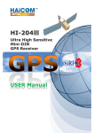
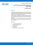
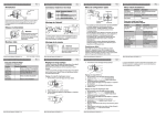
HI-203E
GPS Receiver
1
General description of what GPS
is and how it works.
GPS (Global Positioning System) is the only system today able to show
you your exact position on the Earth anytime, in any weather, anywhere.
GPS satellites, 24 in all, orbit at 11,000 nautical miles above the Earth.
They are continuously monitored by ground stations located worldwide.
The satellites transmit signals that can be detected by anyone with a
GPS receiver. Using the receiver, you can determine your location with
great precision.
The satellites are positioned so that we can receive signals from six of
them nearly 100 percent of the time at any point on Earth. You need that
many signals to get the best position information. Satellites are equipped
with very precise clocks that keep accurate time to within three
nanoseconds- that's 0.000000003, or three billionths of a second. This
precision timing is important because the receiver must determine
exactly how long it take s for signals to travel from each GPS satellite.
The receiver uses this information to calculate its position.
Although GPS was designed for military use, many thousands of civi
lians make use of it. The satellites actually broadcast two signals, one is
only formilitary use, and one can be used by both military and civilians.
Since GPS is passive (you only need to receive the signal), there are no
restrictions on who can use the signal available to civilians.
GPS technology can be used in avariety of fields besides providing
navigation for vehicles on the sea, in the air and on the ground. GPS
applications also include keeping track of where afleet of trucks, trains,
ships or planes are and how fast they are moving; directin gemergency
vehicles to the scene of an accident; mapping where a city's assets are
located ; and providing precise timing for endeavors that require largescale coordination.
2
GLOBAL POSITIONING SYSTEM
HI-203E GPS RECEIVER
Pin Assignment
1800±30mm
Connectors
1
1 3 5
2
2 4 6
PS/2 Connector
Color
Function
CN1
Green
TX
5
White
RX
4
Red
VCC
2
Black
GND
1
1 Min Din: 6 pin male
connector
2 Wire: 3.6 ± 0.1mm
Pocket PC
HI-203E PS/II GPS receiver Can Connecting to a female PS/II
Connector. One end from the female Connector is
+12V car charger (charging PDA and GPS
receiver simultaneously) the other end form
the female PS/II connector is the PDA
connector for connecting your PDA.
For notebook PC use:
HI-203E PS/II can also connect
with a PS/II to DB9 PS-232 serial
cable or USB connector.
3
1. HI-203E Series Introductions
HI-203E is a GPS receiver with PS/II mini-DIN
interfaces and built-in active antenna for high
sensitivity to tracking signal. HI-203E is well suited
to system integration and users who use any kinds of
mobile devices, such as, PDA, notebook PC, Tablet PC, etc.
It satisfies a wide variety of applications for car navigation,
personal navigation or touring devices, tracking and marine
navigation purpose. Users can simply plug it into a PDA or
other type of handheld PC running with suitable mapping
and routing software for navigation.
1.1 Standard Package
Before you start up, make sure that your package includes
the following items. If any items are missing or damaged,
contact your dealer immediately.
• HI-203E GPS Receiver unit
• Suction CUP
• User Manual CD (including
User Manual, HaiTest Testing
Program
Optional Accessories:
• PS/II to PDA connector
and car charger
• PS/II to DB9
adapting cable
• PS/II to USB
adapting cable
HI-203E-XXXX
(Pocket PC Plug)
HI-203E-USB
HI-203E-DB9
4
SECTION 1
INTRODUCTION
1.1 OVERVIEW
The HI-203E GPS Receiver is intended for use in a wide range of
applications. The receiver simultaneously tracks up to twelve satellites,
provides accurate satellite positioning data with fast time-to-first-fix
(TTFF) and low power consumption. It is designed for high performance
and maximum flexibility in a wide range of applications including mobile
asset tracking, in-vehicle
telematics and so on. The
performance, minimizes
requirements. The HI-203E
automotive guidance, location sensing,
highly integrated receiver achieves high
board size and power consumption
is designed to withstand harsh operating
environments; however, it should be used inside an enclosure as a part
of the application product designed by the system integrator.
1.2 FEATURES
The HI-203E GPS receiver offers following features:
• T welve parallel tracking channels
• F ast TTFF and low power consumption
• Compact design suitab le for applications requiring small space
• On-board rechargeab le battery sustained real-time clock and memory
•
•
•
•
•
5
for fast satellite acquisition during power-up
High accur acy one-pulse-per-second output
Suppor ts NMEA-0183 protocol
Full na vigation accuracy achievable with Standard Positioning Service
Optimiz ed for navigation in urban-canyon environments
A utomatic cold start with no user initialization required
SECTION 2
RECEIVER OPERATION
Upon power up, after initial self-test has completed, the HI-203E will begin
satellite acquisition and tracking process. Under normal open-sky condition,
position-fix can be achieved within approximately 45 seconds (within 15
seconds if valid ephemeris data is already collected from recent use). After
receiver position has been calculated, valid position, velocity and time
information are transmitted through the on board serial interface.
The receiver uses the latest stored position, satellite data, and current
RTC time to achieve rapid GPS signal acquisition and fast TTFF. If the
receiver is transported over a large distance across the globe, cold-start
automatic-locate sequence is invoked. The first position fix may take up
to five minutes searching the sky for the GPS signal. The acquisition
performance can be improved significantly if the host initializes the
receiver with a rough estimate of time and user position.
As soon as GPS signal is acquired and tracked, the HI-203E will
transmit valid navigation information through its serial interface. The
navigation data contains following information:
• Receiver position in latitude, longitude, and altitude
• Receiver velocity
• Time
• DOP error-magnification factor
• GPS signal tracking status
The HI-203E will perform 3D navigation when four or more satellites are
tracked. When three or fewer satellites are tracked, altitude-hold is enabled
using the last computed altitude and 2D navigation mode is entered.
With signal blockage or rising and setting of the satellites, where a
change in satellite constellation used for position fix occurred, large
position error may result. The HI-203E incorporates a proprietary
algorithm to compensate the effect of satellite constellation change, and
maintains an accurate smooth estimate of the receiver position, velocity,
and heading.
6
2.1 RECEIVER SPECIFICATIONS
FEATURES
General
Sensitivity
DESCRIPTIONS
L1 frequency, C/A code, 12-channel
-165 dBW minimum
Update Rate
1Hz
Position: 25m CEP without S/A
Velocity : 0.1/sec without S/A
Cold start: < 150sec (typical)
Warm start: < 45sec (typical)
Accuracy
Acquisition
Reacquisition
Dynamics
Operation Temperature
Storage Temperature
Operating Humidity
Primary Power
Current Consumption
Serial Interface
Protocol
Datum
Antenna
NMEA Message
Dimension
Hot start: < 15sec
<100msec
Altitude: -1000m to 18000m
Velocity: 500m/sec
Acceleration: g
-20°C to +75°C
-55°C to +90°C
5% to 95%
+3.8V ~ 8V DC
125mA @ 3.3V
RS-232
4800/9600 baud, 8-None-1
NMEA-0183 v2.20 @ 4800/9600 baud, 8-None-1
219 standard datum, default WGS-84
On-Board Patch Antenna
GGA, GLL, GSA, GSV, RMC, and VTG
41mm x 58mm x 20mm (W x L x H)
2.2 LED INDICATOR
LED off
LED flashing
LED on
7
Receiver Switch Off
Signal Searching
3D Position Fixed
SECTION 3
HARDWARE INTERFACE
3.1 MECHANICAL DIMENSIONS
Unit:mm
Top View
41±0.2
I/O Cable
Lateral View
20±0.2
I/O Cable
Bottom View
LED indicator
41±0.2
I/O Cable
CPU
58±0.2
8
3.2 RF MODULE HARDWARE INTERFACE
1
2
3
4
5
RFIC
6
7
8
9
10
Pin
1
2
3
4
5
6
7
8
9
10
9
Description
NC
NC
Vcc Input :3.3V
CTRL :Input signal for RF module power-saving control
GND : Power and signal ground
REF Out : 16.367MHz reference output
GND : Power and signal ground
IF Out :4.092MHz IF signal output
NC
NC
3.3 BASEBAND HARDWARE INTERFACE
1
A3
2
A1
3
6
4
5
6
1
7
8
B3
B1
9
10
The 10 pin-connector is the same as the RF connector.
A1 : GND, Ground
A2 : 1PPS Valid Signal (1:Valid, 0:Invalid)
A3 : 1PPS
B1 : TX, Serial port output (GPS navigation output)
B2 : RX, Serial port input
B3 : Vcc, Power supply input, 3.8V ~ 8.0V DC unregulated
The following is a functional description of the pins on the 6-pin interface
connector.
Pin 1. TX, Serial port output (GPS navigation output)
Pin 2. RX, Serial port input
Pin 3: Vcc, Power supply input, 3.8V ~ 8.0V DC unregulated
Pin 4: GND,Ground
Pin 5: 1PPS Valid Signal (1:Valid, 0:Invalid)
Pin 6: 1PPS
10
3.4 ONE-PULSE-PER-SECOND (1PPS) OUTPUT
The one-pulse-per-second output is provided for applications requiring
precise timing measurements. The output pulse is 1usec in duration.
Rising edge of the output pulse is accurate to +/-1usec with respect to
the start of each GPS second. Accuracy of the one-pulse-per-second
output is maintained only when the GPS receiver has valid position fix.
The 1PPS output is always generated when the GPS receiver is
powered-on. Proper adjustment of the 1PPS output to align with the
GPS second requires calculation of the receiver clock offset and clock
drift-rate as part of the position-velocity-time (PVT) solution. When
enough satellite signals are received to generate valid position fixes, the
1PPS output is adjusted to align with the GPS second in several
seconds. When the 1PPS output is brought in sync with the GPS
second, the 1PPS Valid Signal on the I/O pin becomes active (HIGH);
when the 1PPS output is not yet in sync with the GPS second, the 1PPS
Valid Signal remains inactive (LOW).
As long as enough satellite signals are received to generate valid
position fixes, the 1PPS output remains synchronized to the GPS
second, and the 1PPS Valid Signal remains active. If signal blockage
prevents the receiver from generating valid position fix, the 1PPS output
will drift away from the GPS second and the 1PPS Valid Signal will
become inactive. Upon re-acquiring enough satellites to generate
consecutive valid position fixes, the 1PPS Valid Signal will become
active again, signaling that the 1PPS output is again synchronized with
the GPS second.
For best stable operation of the 1PPS signal, it is to be operated in static
environment having clear view of the sky.
11
SECTION 4
SOFTWARE INTERFACE
This section describes the details of the serial port commands through
which the HI-203E is controlled and monitored. The serial port
commands allow users to set the receiver parameters, configure output
message type, and retrieve status information. The baud rate and
protocol of the host COM port must match the baud rate and protocol of
the GPS receiver serial port for commands and data to be successfully
transmitted and received. The default receiver protocol is 4800baud, 8
data bits, 1 stop bit, and none parity.
4.1 NMEA OUTPUT MESSAGE SPECIFICATION
The HI-203E supports NMEA-0183 output format as defined by the
National Marine Electronics Association (http://www.nmea.org). The
currently supported NMEA messages for GPS applications are:
GGA
GLL
GSA
GSV
RMC
VTG
Global Positioning System Fix Data
Geographic Position Latitude / Longitude
GNSS DOP and Active Satellites
GNSS Satellites in View
Recommended Minimum Specific GNSS Data
Course Over Ground and Ground Speed
4.1.1 NMEA Checksum Calculation
The optional NMEA checksum can be enabled or disabled when setting
up the NMEA protocol. The checksum consists of a "*" and two
hexidecimal digits derived by exclusive-OR of all the characters
between, but not inlcuding, the "$" and "*" characters.
12
APPENDIX B
DEFAULT VALUES
The product has the following factory preset default values:
Datum: 000 (WGS-84)
NMEA Enable Switch:
000 (WGS-84)
GGA ON
GLL OFF
GSA ON
GSV ON
RMC ON
VTG OFF
Checksum ON
Baud Rate:
4800 Baud
Elevation Mask:
DOP Mask:
5 degrees
DOP Select: Auto
GDOP: 20
Receiver Operating Mode:
PDOP: 15
HDOP: 8
Normal Mode (without 1PPS)
Commands can be issued to the HI-203E to change the settings of the
receiver. The new settings will remain effective on next power-on as long
as the on-board rechargeable backup battery is not discharged. After
the backup battery is discharged, factory preset default settings will be
used.
13
TROUBLESHOOTING
Problem
Reasons
No Position Weak or no GPS signal
output
but can be received at the
timer
is place of HI-203E unit
counting
Solutions
Connect
an
external
antenna to HI-203E and
place the antenna under a
open space, then, press
'Reset'
At outdoor space but GPS To try again, go to outdoor
signal is blocked by and
press
'Reset'
or
building or car roof
connect external antenna
on the side of HI-203E to
improve the poor GPS
signal
Execute Fail
Wrong CPU type
PocketPC support multiple
typs of CPU. Make sure you
download
the
correct
testing
(or
mapping
software). You can use the
PDA smart menu's 'setting'
function to see wether the
CPU type is correct or not.
Can's open The PS/II connector did
COM port
not insert correctly or
some other application is
the COM port
Insert all HI-203E connector
firmly or close all other
application that occupied
the COM port
Can not find Poor connection
HI-203E
Check
firmly
No signal
HI-203E
if
insert
No action for few minites
may causes PocketPC Close all applications and
into the power saving exacute it again to re-open
mode. It could close the the COM port
COM port at the same
time.
Weak or no GPS signal Put HI-203E to an open
when
using
HI-203E space or car roof, then,
indoor or inside the car.
press the Reset button
14
GPS Receiver
Offizielle Vertretung Schweiz:
Sintrade AG
Kriesbachstrasse 30
CH-8600 Dübendorf
www.sintrade.ch