1
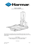
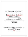
Optimal Design Report
Single Hand Manual Driven Wheelchair
Team #5
Jordan R. Smith
Kayla Gosse
Leah McElhaney
Project for Client: Danielle Giroux
Client Contact Information:
Dave and Suzanne Giroux
53 Charlotte Dr, Tolland, CT 06084
[email protected]
860-604-0893
1. Optimal Design Project 5
1.1 Introduction
The team has begun designing the single hand manual wheelchair for a client who does
not have motor control in their left hand. The client has expressed a need for an easier way to
navigate her wheelchair using only one hand, while still being able to control how fast it goes
and which way it steers. There were three alternative designs that the team took into careful
consideration when selecting the optimal design. The first design incorporates a one arm lever
system that can be used in a pumping fashion to move the chair in forward and reverse directions
with the turn of a switch. The client’s specifications called for a braking system to be built into
the wheelchair so that the client can easily stop movement on command. The braking system
involved with this design involves simply switching the gears into neutral and pulling back on
the lever arm to stop movement. The second and third designs both incorporated a double-railed
wheel setup on the right side of the wheelchair so that the client can propel the chair forward by
spinning the rim associated with the respective wheel. There will be two rails on the right side-one rail controlling movement of the right wheel and another rail controlling movement of the
left wheel. A gear box will allow the client to switch between control of a single wheel or
control of both wheels in order to steer the wheelchair in different directions.
The fall back of these designs is that a separate braking mechanism must be installed.
Since the second and third alternative designs incorporated the same double-rail movement
system, they had different braking mechanisms. The second design incorporated a set of disc
brakes into the system that are similar to those in a motor vehicle. The disc brakes would be
located within the rim of the wheel and around the axle. When the client applied the brakes, the
discs would press against the wheel to cause friction in order to prevent movement. The third
alternative design incorporated a set of hand brakes similar to what is seen on a standard bicycle.
The hand brakes would function using a set of rubber pads that attach to a clamp around the tires.
When the client desired to slow down or stop, they would squeeze a lever that would create
tension in a wire connected to the brake pads. This would cause the clamp holding the brake
pads to close, and the pads would create friction on the tire to prevent movement.
The group discussed these three alternative designs and determined that the first one
using the one arm lever system would be best for a number of reasons. One of the advantages of
this system is that it is easy to control and steer. There is only one lever that sticks out on the
right side that allows the client to control movement of the wheelchair with ease. Figure 1 below
shows a sample representation of this one arm drive lever mechanism. Another advantage over
the other designs is that the existing system already includes a braking mechanism. Therefore, it
will be less costly and more time effective for the group to use this system because they will not
have to look into purchasing a separate braking system to attach to the final product.
One of the advantages of this project is that each of the designs includes a one hand drive
mechanism that has been built and is on the market for sale. The two systems that have been
discussed are both available for purchase and use with specific wheelchair models only.
However, one of the complications of this project is that these wheelchair models are not able to
collapse. There are no one hand drive mechanisms out on the market that are capable to use with
an existing folding wheelchair. One of the specifications that the client requires is that the
wheelchair has the ability to collapse so that it can be transported and stored easily. Therefore,
the challenge of this design project is to take the existing one hand drive lever system and
modify it to fit a folding manual wheelchair.
Figure 1: First alternative design representing one arm drive lever system
1.2 Subunits
1.2.1 Conventional Folding Wheelchairs
There are many different types of wheelchairs, ranging from lightweight, portable, heavyduty, manual, powered, folding, sport, and reclining. These different types all have benefits over
others and are for use with a variety of different purposes. The type that the group will use for
this design will be a conventional folding wheelchair for the sole purpose of being lightweight
and portable. The client has specified that a folding manual wheelchair is necessary for this
project so that the family can easily transport it from one place to the other. An example of a
traditional folding wheelchair is shown in Fig. 2 below.
Figure 2: Example of a standard manual folding wheelchair
A standard non-powered (manual) wheelchair must be controlled manually by two hands.
There are two different types of manual wheelchairs, which are folding and non-folding. All
standard manual wheelchairs have four wheels--two large in the back and two small in the front.
The two front wheels are much smaller than the rear wheels and this is because they function for
stability and are responsible for guiding the chair in the right direction when the operator makes
a turn. The front wheels are able to swivel a full 360 degrees, while the rear wheels do not
swivel at all. The purpose of the larger rear wheels is to allow movement of the wheelchair.
Notice the large metal hand-rail in the sample wheelchair in Fig. 2. The operator must grab the
hand-rail and rotate the wheels on the left and right sides of the wheelchair in order to allow the
chair to move forward. The operator turns by simply stopping rotation of the wheel on the side
of the wheelchair where they wish to turn.
The client for this project does not have motor control in their left hand, which makes it
very difficult to control movement on the left side of a standard manual wheelchair. This makes
it extremely difficult for the client to propel the chair forward in a straight direction, or to steer to
the left or right. The client normally uses her manual wheelchair within the home because it is
easier to control in a smaller environment when compared to a power wheelchair. The purpose
of this project is to adapt a mechanism that can allow the client to move and steer a manual
wheelchair using only one hand. Another requirement from the client is that the one hand drive
wheelchair be able to fold so that the family can easily transport it when necessary.
1.2.2 Invacare Cyclical Lever Drive
In order to produce a final product that will be functional, the team will design a system
that incorporates all the specifications and requirements to meet the client’s needs. The team
will pull from multiple resources in order to satisfy the needs of the final product. The optimal
design for this wheelchair involves the use of a product manufactured by the Invacare company.
Invacare is a medical supply company that produces wheelchairs and wheelchair accessories for
clients with disabilities. The system that the team will be purchasing will be the Cyclical Lever
Drive (CLD) mechanism that functions as a lever to control movement of the wheelchair using a
single hand. Figure 3 below shows an example of the CLD system. This system is
manufactured specifically to fit Invacare 9000 Series wheelchairs for client’s like Danielle who
have loss of motor control in their left hand.
The way the system functions is that it incorporates a lever arm that must be pumped in a
forward motion to allow the wheelchair to move. The lever is attached to a transmission drive
system, which is attached to the axle of the rear wheels. The client can control what direction
they would like their chair to move--forward or reverse-- by simply switching the gear in the
transmission. Movement of the wheelchair can be stopped by pulling the lever arm back to
prevent movement of the wheels. Further description of each of the components will be
discussed further on. The CLD system is available for purchase from a number of different local
retailers, which will be discussed in section 1.2.10 of this report.
Figure 3: Example of CLD system for Invacare 9000 Series wheelchairs
One of the advantages of the CLD system is that it functions using only one hand. The
purpose of this project is to design a system that can be applied to a standard manual wheelchair
for the client to control using only their right hand. The CLD mechanism also has a built in
braking system that functions to stop movement of the wheelchair upon command. This is one
of the safety features that the client had recommended for the final product. There are also a few
drawbacks to the CLD system as well. For instance, the system does not fit any standard manual
wheelchair--it will only fit the Invacare 9000 Series wheelchairs, represented in Fig. 3. This
makes it a challenge for the team to incorporate this system on any random existing manual
wheelchair that the team happens to come across when searching for potential parts. The team
may not find an Invacare 9000 Series wheelchair to fit their budget, which makes it a challenge
to be able to apply the CLD system to any standard manual wheelchair.
Another major drawback of the Invacare CLD system is that the online specifications do
not indicate whether it can be applied to a folding wheelchair. The Invacare 9000 Series
wheelchair products are standard manual wheelchairs, but do not collapse for easy portability.
Therefore, the team cannot use an Invacare 9000 Series wheelchair because it does not meet the
specifications and needs of the client. The client has requested that the wheelchair be able to
fold for easy transport and portability. The team must adapt a method to incorporate the CLD
system into any standard folding wheelchair in order for this project to be successful. The most
challenging portion of this project will be designing a method for the existing single arm drive
system to fit to any standard folding wheelchair. The team cannot simply follow the detailed
instructions for installing the one arm drive system because those instructions will be specific to
the Invacare 9000 Series wheelchair. In order to be successful, the team must use the installation
instructions as a guide to fitting the one arm system on another manual wheelchair that is able to
fold.
1.2.2 Drive Arm Assembly
The CLD system is broken down into many different components, each serving a purpose
in the overall functionality of the wheelchair. The first major component is the arm assembly
and Fig. 4 below shows a diagram of the basic setup. Basically, there is a two foot long handle
that attaches to the fork of the front right wheel to control the steering and forward and reverse
movements of the wheelchair. The drive arm functions as the main method of control for the
client. The arm is moved back in forth in a pumping action in order to propel the wheelchair
forward. With each pump, the lever system moves a set of gears attached to the axle, and this
provides movement to the rear wheels. The arm is attached to the front wheel via a rotating
mechanism, which allows the client to steer the direction of the wheelchair by turning the lever
arm left or right. The client will also be able to adjust the height of the lever arm by simply
unscrewing a nut that holds it in position. The lever arm will be able to slide up and down to the
client’s desired height and can be securely tightened in place. This will allow the client to setup
the arm assembly in a comfortable position in order to minimize discomfort while the wheelchair
is in use.
Figure 4: CLD Drive Arm Assembly
1.2.3 Fork and Steering Assembly
The second major component is the fork and steering mechanism. Figure 5 below shows
a diagram of the basic fork and steering assembly. These components are responsible for
holding together the drive arm and the front right wheel. The fork is a common part that attaches
wheels because it has two prongs that go on each side of the wheel with an axle holding it
together in the middle. This piece is made of aluminum or stainless steel and must be strong
enough to support the weight of the wheelchair without falling apart. At the base of the drive
arm (and the top of the fork assembly) there is a rotating fork stem and caster headtube that are
essential for the 360 degree rotation of the wheel. The fork stem is placed within the caster
headtube and the hex nut prevents the fork stem from being removed. The fork stem is free to
rotate within the caster headtube with very little friction. This fork assembly is attached to the
lever arm component and this entire assembly makes the wheelchair able to turn in any direction
by applying simple movement to the lever arm.
Figure 5: CLD Fork and Steering Assembly
1.2.4 Rear Wheel and Axle
The third set of components of the one arm drive system are the rear wheels and axle.
Figure 6 below shows a diagram representing how these components function as the lever arm is
pumped. When the operator of the wheelchair desires to move forward, they will pump the lever
arm and this will move the transmission assembly and transmission rear hub. The motion of
these parts will essentially spin the rear wheel hub spokes and axle, which will ultimately spin
the right and left wheels. The rear wheels are connected to the same rotating axle, so both
wheels will rotate together at the same speed.
Figure 6: CLD Rear Wheel and Axle Assembly
The most difficult challenge in this project is to design a one hand drive system that will
be able to attach to a standard folding wheelchair. The existing CLD system does not have the
capability of easily attaching to a folding wheelchair, which makes it difficult to use this type of
mechanism. It is necessary for the team to design a modification to this existing CLD system in
order to apply it to a standard folding wheelchair according to the client’s specifications. The
most logical way to go about this is to create a mechanism by which the rear axle can fold. If we
recall the folding manual wheelchair in Fig. 2, we can observe the folding mechanism and try to
adapt a similar system for use in the single hand manual drive wheelchair. Traditional manual
wheelchairs have a rear axle that splits in the middle and is able to collapse on itself. This axle is
separated in the middle by a joint that is locked in place until the user decides to fold the
wheelchair. Once the user decides to fold the wheelchair, they must unlatch the mechanism
holding the axle joint in place and the wheelchair is easily able to collapse for portability and
storage. Figure 7 shows a representation of this folding axle mechanism that the team will use to
modify the existing CLD system.
Figure 7: Example of folding hinge that will be used on one arm wheelchair
When designing the single hand manual wheelchair, the group will use a similar folding
hinge mechanism and adapt it to the CLD system. This is the easiest way for the team to cover
all the specifications, which include the ability of the wheelchair to move with only one hand,
stop on command, and fold for easy portability and storage. The team will use the existing CLD
rear wheel axle and modify it so that it can collapse when the wheelchair is in folded position.
This will be done by applying a simple hinge in the middle of the axle so that the two sides fold
on top of one another. This method is almost an exact replication of what is seen in existing
manual wheelchairs, however there is a set of rear wheel hub spokes and slot that the team must
work around and take into consideration when coming up with a design. This is definitely the
most difficult aspect of the design that the group faces for this project.
1.2.5 Transmission
The transmission component of the wheelchair design is responsible for allowing the
operator to change gears between forward, neutral, and reverse movement. This piece comes
with the CLD system and is part of the lower portion of the lever arm. It basically attaches to the
wheelchair side frame via a set of screws and this is what ultimately holds the control arm in
place. The transmission will function using a small lever that protrudes out the top. This lever
will be accessible to the client on the right side of the wheelchair. There are three different gears
as mentioned before--forward, neutral, and reverse. When the client desires to move in the
forward direction, they will engage the gear using the small lever. The same process is necessary
for moving in the reverse direction as well. Figure 8 below demonstrates the basic setup of the
transmission system.
One of the things that is important to take into consideration is how difficult is is for the
client to be able to switch gears. The shifting arm is a very simple setup and should not require a
lot of energy to move. The pumping action of the control arm on the wheelchair is also another
concern because it requires that the client make several pumping motions back and forth to move
the wheelchair in any direction. The group will work closely with the client to ensure that they
are able to operate the wheelchair with ease and that it does not require a high degree of physical
strain to use.
Figure 8: CLD Transmission and Gear Lever Assembly
1.2.6 Ability to Disengage
One of the best features of this wheelchair is the ability to disengage the gears. This is
really beneficial if the operator decides they do not want to control the wheelchair by themselves.
This feature allows the ability for someone to disengage the gears so that they can manually push
the wheelchair from behind. The disengaging mechanism is something that functions using a
spring and pin. The bottom of the lever arm contains a piece that attaches to the front wheels
like what is shown in Fig. 9 below. The pin can simply be removed from its holder on the front
wheel to allow the wheelchair to be disengaged from the control arm setup.
Figure 9: Ability to disengage CLD system
1.2.7 Wheel Lock
Another important feature is the ability to lock the rear wheels in place. This is useful if
the operator wants to prevent movement of the wheelchair if they are getting in or out. This is an
important safety feature because if the wheelchair moves while the client is sitting down or
standing up then it may cause the client to slip and get injured. The wheelchair locking
mechanism is shown in Fig. 10 below. The functionality of this design allows a lever to be
turned that presses a brake pad against the tires to prevent movement. This lever operates with a
simple turn and can lock the wheel in place. There are two wheel locks--one for each side of the
wheelchair to attach to the large rear wheels. The small front wheels do not have locking
mechanisms.
Figure 10: Ability to lock wheel in place
1.2.8 Wheel Braking
Safety of the one arm drive wheelchair is a very important concern. The group is taking
into account a braking mechanism that will allow the client to easily stop the wheelchair on
command. Some of the alternative designs discussed ideas about disc brakes and hand brakes for
the one arm manual drive wheelchair. However, these ideas needed separate mechanical drive
and braking mechanisms. The CLD system incorporates its own braking mechanism within the
design. In order to apply the brakes, the operator simply pulls back on the arm drive lever. This
motion can even be performed when the chair is in forward or reverse gears. An image
representing the braking system and brake pads is shown in Fig. 11 below. When the operator
pulls back on the lever arm, it will press the brake bad against the rubber tire, which will hinder
movement of the wheels. The advantage of using this system is that there are very little
mechanical pieces or wires sticking out. If the team were to incorporate a hand brake system
similar to that seen in bicycles, there would be many metal wires sticking out and running from
the front to the back of the wheelchair. The existing system shown in Fig. 11 eliminates all these
wires and large contraptions and keeps the design relatively simple.
Figure 11: CLD braking mechanism
1.2.9 Safety Features
The team will also be taking into account the safety features used in a restraint system for
a motor vehicle. The client’s minivan already has the necessary wheelchair tie downs for the
wheels, however the team must design the buckle system for the seat on the wheelchair. Figure
12 shows a typical image of a client riding in a wheelchair inside a motor vehicle. Both the front
and rear wheels are safely secured to the floor of the minivan so that the wheelchair cannot
move. The team will attach a restraint system to the wheelchair to ensure that the client is
secured while riding in the family’s minivan. There will be a strap that goes across the client’s
chest and lap that will buckle into place just like a standard seat belt in a car.
Figure 12: Example of restraint system
1.2.10 Proper Support
One of the most important features of this wheelchair is the support system for the client.
The team will be working closely with Danielle’s physical therapist to ensure that the wheelchair
provides proper posture and support. The team will invest in padding including hip guides, head
rest, and pummel so that they can ensure the client gets the support she needs. Figure 13 shows
an example of a headrest that will be applied to the single hand manual wheelchair. The headrest
will be approximately 8 inches tall, by 5 inches wide. It will be made out of soft foam padding
and will be positioned behind the client’s head according to the recommendations from her
physical therapist.
Figure 13: Example of headrest used in optimal design
Figure 14 shows the exact pummel that the team will be using for the single hand manual
drive wheelchair. The pummel goes at the base of the seat between the client’s legs to make sure
that their legs do not cross. The device will be attached to the wheelchair using the screw holes
on the left side. It is necessary to incorporate a hinge system so that the pummel can be folded
down to allow the client to easily enter or exit the wheelchair.
Figure 14: Pummel used on Single Hand Manual Drive Wheelchair
Figure 15 shows an example of hip guides that will be used on the wheelchair. The team
will discuss the proper seating position with Danielle’s physical therapist to make sure these hip
guides are aligned in the correct position.
Figure 15: Example of hip guides for client support
1.2.11 Detachable Seat
One of the most important features of the single hand drive manual wheelchair is the
ability of it to fold for easy portability and storage. This task will be very difficult with all the
support padding in place, so the team will design a chair that can be easily removed. This chair
will be set into the wheelchair and will contain all the necessary padding and support, including
hip guides, head rest, and pummel. The chair will not be able to fold when the seat is in place.
Once the seat is unbuckled from the wheelchair and removed, it will be able to collapse. The
chair will sit in place via a buckle system. When the operator desires to use the wheelchair, they
will unfold it and set the seat into position. A set of buckle straps will be clipped into place to
secure the seat in position on the wheelchair. The team will purchase a seat similar to the one
shown in Fig. 14 below. This is a seat used in a motor vehicle, but something like this has holes
in the side to allow straps to easily attach to the wheelchair.
Figure 14: Example of detachable bucket seat
2 Realistic Constraints
There are many physical constraints that come into play with the design of this single
hand manual drive system. For example, the team must consider the realistic constraints
associated with the economic, environmental, sustainability, manufacturability, ethical, social,
political, and health and safety concerns. The team must make sure that this design is feasible
and that the final product is beneficial for the client without hindering their safety or wasting
money.
The group will take economic concerns into consideration when designing the single
hand manual drive wheelchair. The purpose of the project is to make a wheelchair that can be
fully functional using only the right hand, however the group does not want to design a product
that will be way too expensive. In other words, it is necessary that the costs don’t outweigh the
benefits. In industry, engineers design products, but they will not sell if the production costs are
too high. The company would simply lose money out of the manufacturing of the product. The
same concept applies to our single hand manual drive wheelchair.
Another constraint that the team faces are the environmental impacts of the wheelchair.
The team will not be using any motorized components, so they are not worried about pollutants
that could be harmful to the environment. The team must be careful with what types of materials
they are using and what kind of impact they will have on the environment. If the team were
using dangerous chemicals to construct the wheelchair, then there would be serious impacts on
the environment and safety of the client and team members. However, the team will not be using
any potentially dangerous chemicals or pollutants in the fabrication of this product, so it is not
necessary to be particularly concerned about the impact on the environment.
The manufacturability of the product is a large concern that the team must take into
consideration when designing the wheelchair. The team does not want to design something that
will be extremely difficult to produce or hard to use. The design should be kept as simple as
possible, and consideration into every minute detail is critical to ensure that the final product is
successful. The constraints of the project should be within reason so that the team is not trying
to build something that is close to the impossible. The feasibility of the project is something that
is critical both in the senior design course and in real world industry.
The sustainability of the product is very important as well because the team does not
want to create something that will fall apart after a short period of use. The final product should
be strong and sturdy and able to support years of use without falling to pieces. The group will
ensure to double check all mechanical parts on the wheelchair before turning it over to the client
to make sure that everything is safe and that bolts and screws are tightened in place. Should the
unexpected happen and something to go wrong, the group will provide an instruction manual for
the client to perform simple repairs and preventative maintenance.
The social concerns have to do with how the client interacts with her environment and the
people around her. The client has specified that the wheelchair not look so robotic and that
special padding or paint be used to cover large protruding parts if necessary. The team will keep
the mechanical parts within reason so that the wheelchair will not stand out in the client’s
environment. The family would like the wheelchair to look like any other ordinary wheelchair to
not draw a large amount of attention. The group also does not want to design something that will
be too difficult for the client to use in her environment. The lever arm system must be a very
simple design so that the client can control it with ease. If the lever arm were too difficult to use,
it would defeat the purpose of making the wheelchair to begin with.
Health and safety concerns are by far the most important aspect of the single arm manual
wheelchair design. The team will take many precautions into consideration when designing the
final product to ensure complete operator safety. The first safety component is the use of seat
restraints. These can be used for when the client is in a motor vehicle so that they properly
restrain the operator in case of a motor vehicle accident. Another health and safety component is
the position of the seating in the wheelchair. The team will work closely with the client’s
physical therapist to ensure that the right hip guides, head rest, and pummel are used and
positioned correctly so that they do not harm the client’s health. The third health and safety
concern is the ability to stop the wheelchair on command. The chair will have a built in braking
mechanism so that the operator will simply have to pull back on the one arm drive mechanism
and the wheelchair will stop. This will function using a set of brake pads that will enclose on the
tire to stop movement. Another safety feature is the ability to lock the wheels. This will be
useful if the client is getting into or out of the wheelchair and will prevent the wheelchair from
moving during the process.
3 Safety Issues
The team will take into account many safety and health concerns when designing the one
arm drive manual wheelchair. For example, many of the possible safety concerns necessary to
address are components that have to do with electronics, mechanical pieces, biological hazards,
decontaminants, chemical hazards, radiation, thermal factors, biocompatibility, and host reaction
to materials. Fortunately, there are no materials in this project that are being inserted into the
human body, so the team does not need to worry about biocompatibility and how the body will
react to foreign substances. There are also no electrical concerns associated with this project
because the team will not include any electronics in the design of the one arm drive manual
wheelchair. However, there are always potential safety concerns with the mechanical pieces of
the wheelchair and the possibility of someone pinching their hand or fingers in a moving
component. The concerns are very minimal with the design of this single hand manual drive
wheelchair, but it should be noted that it is always possible for it to happen. The team has
addressed this issue by using an existing one hand manual drive system that has already been
tested against these types of hazards. The rotating mechanical pieces are located underneath the
wheelchair and are out of the way from any potential hazard. In order for someone to pinch their
fingers, they would literally have to have their hand under the wheelchair while it is in use.
Therefore, the chances of injury are very low due to mechanical components based on the
location of the moving pieces under the wheelchair.
The team must be careful with what types of materials are used for the wheelchair. The
team will not be using anything that is radioactive or conducts a lot of thermal energy that could
be dangerous in any way to the client. Again, the client’s health and safety is the number one
concern for this project. The team will use standard metals like aluminum, steel, or titanium that
are strong and reliable and are harmless to the client in terms of chemical or radioactive
exposure.
4 Impact of Engineering Solutions
The engineering solution to this problem is not an extremely difficult matter. The team
will take an existing product out on the market and adapt it to fit the client’s purposes. The
global impact to the engineering solution is that the world might see a new way to design the
traditional manual wheelchair. Manual wheelchairs have always been made to operate with two
hands, but it’s possible that in the future they will be designed similar to the one the team is
building for Danielle. The world could see a change in how wheelchairs function in order to
provide client’s like Danielle with an easier way to get around. This type of design does not
have any long term influences on the economy. If the design were ever put into industry, it may
perhaps be modified in the future to be less costly to produce. This would allow the company to
make more money by keeping production costs low and market value high. This design has very
little environmental impacts because it does not contain any radioactive or toxic chemicals that
may degrade or corrode to have a negative impact on the environment. The wheelchair will be
made from strong steel or aluminum components that do not have any negative impacts on the
environment. The team would have to take precautions if they were working with hazardous
materials that could cause potential safety and health implications. The overall societal influence
that this design has is very small in terms of the entire society. However, if we were to take into
account the different that it makes to the client, the impact that it has on her ability to interact
with society is phenomenal.
5 Life-Long Learning
The team has learned a lot through the design of the one hand manual drive wheelchair.
Before beginning this project, the team never knew that such a system existed on the market.
The group has been exploring many different braking options and has learned the difference
between hand brakes and disc brakes based on how they function. Both types are made to stop
movement of the wheels to slow down the wheelchair’s speed, but they work differently in many
ways. Disc brakes are more difficult to apply to this type of wheelchair when compared to hand
brakes. The downside is that hand brakes are harder for the client to use. The team was able to
find a system that allows the arm drive and brake system to be combined together for easy use.
The brake system acts similar to hand brakes where there is a brake pad that rubs against the tire
to prevent movement. However, since it is incorporated into the hand drive mechanism, it is
easier to use because all that must be done is that the operator pulls back on the arm drive when
they desire to slow down. The most important thing the team has learned about is the condition
of cerebral palsy and what sort of implications it has on the client’s mobility. The team is
helping to improve the life of someone with disabilities through the design of the single hand
drive manual wheelchair.
6 Related Links
The following are related links that show more information about the Invacare CLD
mechanism:
● Invacare CLD Product information:
http://www.phc-online.com/v/vspfiles/docs/CLD-lever.pdf
● Invacare CLD Product Manual:
http://www.invacare.com.au/ass/content/930/966/poirier-user-manual-aus.pdf
● Video demonstrating use of CLD system:
http://www.youtube.com/watch?v=eGkV5apxcvs
● Local Invacare vendors:
http://www.invacare.com/cgi-bin/imhqprd/inv_dealer/dealer_results.jsp?s=0
● Invacare CLD system for sale online:
http://www.phc-online.com/CLD_LEVER_DRIVE_LH_6_INSTALL_p/inv-ldr96li.htm
7 References
http://folduptables.co.uk/category/folup-chair/
http://www.rehab.research.va.gov/jour/00/37/1/shaw.htm
http://www.therafin.com/adjustableanglehipguidehardware.htm
http://www.invacare.com/doc_files/1087937.pdf
http://www.phc-online.com/v/vspfiles/docs/CLD-lever.pdf
http://www.j-specperf.ch/index.php?main_page=product_info&cPath=93_852_860&products_id=2406