1
Multiple-User Intelligent Feeding
Robot for Elderly and Disabled
by
Homeyra Pourmohammadali
A thesis
presented to the University of Waterloo
in fulfillment of the
thesis requirement for the degree of
Master of Applied Science
In Mechanical Engineering
Waterloo, Ontario, Canada, 2007
© Homeyra Pourmohammadali, 2007
Author’s Declaration
I hereby declare that I am the sole author of this thesis.
I authorize the University of Waterloo to lend this thesis to other institutions or individuals for the
purpose of scholarly research.
Signature
I further authorize the University of Waterloo to reproduce this thesis by photocopying or by other
means, in total or in part, at the request of other institutions or individuals for the purpose of scholarly
research.
Signature
ii
Abstract
The number of elderly people are growing very fast all around the world. As age increases the
occurrences of disabilities are increasing which means they are not as active as young people and they
require more assistance from their family members or their care providers in places such as homes,
nursing homes or hospitals. As the number of elderly is growing, the number of people living in long
term care institutions are growing. According to the goals and standards of the health care system,
this population should receive adequate service to be able to have a happy and healthy aging. The fast
growing need for responding to these service requirements will have a great impact on the health care
system. Nowadays many research groups are conducting their work to find different possible
solutions for different kinds of people, environment and service by using the latest available
technology.
Many elderly people are struggling with accomplishing even the most frequent daily activities. To
date, various intelligent, and non-intelligent, machines and robots have been developed to meet the
needs of the elderly and people with upper limb disabilities or dysfunctions in gaining independence
in eating, which is one of the most frequent and time-consuming everyday tasks. However, in almost
all cases, the proposed systems are designed only for the personal use of one individual and little
effort to design a multiple-user feeding robot has been previously made.
The elderly and their feeding requirements in environments such as senior homes with many
elderly residents dining together at least three times everyday have not extensively been researched
before. This, the unavailability of multiple-user feeding systems in the market, and the lack of related
research motivated this project.
The aim of this research is to develop a machine to feed multiple elderly people based on their
characteristics and feeding needs, as determined through observations at a nursing home.
Observations of the elderly during meal times have revealed that almost 40% of the population was
totally dependent on nurses or caregivers to be fed. Most of those remaining suffered from hand
tremors, joint pain or lack of hand muscle strength, which made utensil manipulation and
coordination very difficult and the eating process both messy and lengthy.
In addition, more than 43% of the elderly were very slow in eating because of chewing and
swallowing problems and most of the rest were slow in scooping and directing utensils toward their
iii
mouths. Consequently, one nurse could respond to a maximum of two diners simultaneously and
could manage the needs of all elderly diners with the assistance of the limited number of staff
members available. However, the limited time allocated for each meal and the daily progression of
the seniors’ disabilities made mealtime very challenging.
Based on the caregivers’ opinion, many of the elderly in such environments can benefit from a
machine capable of feeding multiple users simultaneously. Since eating is a slow procedure, the idle
state of the robot during one user’s chewing and swallowing time can be allotted for feeding another
person who is sitting at the same table. Also, since the seniors dined together at a specific time at
several four-seat tables, it would be ideal to assign one feeding device to a maximum of four people
in such institutions in order to dramatically reduce the number, and consequent costs, of machines and
nurses or caregivers.
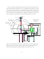
The observations and studies have resulted in the design of a food tray, and selection of an
appropriate robot and applicable user interface. The proposed system uses a 6-DOF serial articulated
robot in the center of a four-seat table along with a specifically designed food tray to feed one to four
people. It employs a vision interface to recognize utensils and cups. Maple software was used for
building the dynamic equations of the robotic system and ADAMS software helped in simulating the
system and evaluating its dynamic behaviour before any prototyping and real-time testing.
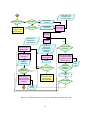
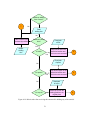
The detailed method that the users, the cameras and the robot manipulator will use to interact with
one another is explained in the context of robot and vision related tasks. These tasks and procedures
are also visualized in a flowchart of the whole system.
iv
Acknowledgements
The completion of this thesis would be impossible without people who really supported me and
believed in me before the beginning of, and throughout my research. I would like to express my deep
and sincere gratitude to both of my supervisors, Dr. Amir Khajepour from the Department of
Mechanical and Mechatronics Engineering and Dr. Jonathan Kofman from the Department of System
Design Engineering. Their wide knowledge and their logical way of thinking have been of great value
for me. Their understanding, encouraging and personal guidance have provided a good basis for the
present thesis. The confidence and dynamism with which Dr. A. Khajepour guided the work requires
no elaboration. Dr. Kofman’s support and assurance at the time of crisis would be remembered
lifelong. On the other hand, their valuable suggestions as final words during the course of work are
greatly acknowledged.
My sincere thanks are due to the official readers, Dr. William Melek and Dr. Catherine Burns, for
their detailed review, constructive criticism and excellent advice during the preparation of this thesis.
I warmly thank them for their valuable advice and friendly help. Their discussions around my work
have been very helpful for this study.
I also want to thank my parents, who taught me the value of hard work by their own example. I
would like to share this moment of happiness with my parents, and siblings. I am very grateful to my
husband, Dr. Ehsan Toyserkani, for all the support he provided throughout my research work.
Without his loving, understanding and guidance I would never have completed my present research. I
am also really thankful to my son, Ali, who was very patient at the time when he needed my company
the most.
At last, not the least, I wish to express my warm and sincere thanks to my friends, Dr. Nasser
Lashgarian Azad, Kiumars Jalali, Matthew Millard, Nasim Paryab, Hanieh Aghighi, Ramesh
Periasamy, and Masoud Alimardani who supported me throughout my work. Finally, I would like to
thank all, whose direct and indirect supports helped me completing my thesis.
v
Dedication
This thesis is dedicated:
To my respectful, thoughtful parents,
my lovely, friendly siblings,
my supportive, well-beloved husband
and
To my happy, creative, energetic, bright, son
who, all, keep my spirit alive.
vi
Table of Contents
Author’s Declaration ......................................................................................................................... ii
Abstract ........................................................................................................................................... iii
Acknowledgements ........................................................................................................................... v
Dedication........................................................................................................................................ vi
Table of Contents ............................................................................................................................ vii
List of Figures ................................................................................................................................... x
List of Tables ................................................................................................................................. xiii
Chapter 1 Introduction ...................................................................................................................... 1
1.1 Objectives and scope ............................................................................................................... 2
Chapter 2 Literature Review .............................................................................................................. 4
2.1 Marketing ................................................................................................................................ 4
2.2 Aging Population and Escalation of Required Services ............................................................ 5
2.3 Self-Feeding Disabilities .......................................................................................................... 7
2.4 Eating As a Daily Activity ....................................................................................................... 9
2.5 Available Feeding Devices ...................................................................................................... 9
2.5.1 Arm Supports.................................................................................................................. 10
2.5.2 Human Extenders for Feeding ......................................................................................... 13
2.5.3 Electro-Mechanical Powered Devices ............................................................................. 14
2.5.4 Assistive Robotic Feeding Systems ................................................................................. 19
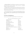
2.5.5 Prices of Feeding Devices ............................................................................................... 24
2.5.6 Discussion on Feeding Devices ....................................................................................... 25
2.6 User Interfaces for Feeding Devices ....................................................................................... 25
2.6.1 User Interfaces for Rehabilitation or Assistive Devices ................................................... 25
2.6.2 Discussion of User Interfaces .......................................................................................... 30
Chapter 3 Observation ..................................................................................................................... 35
3.1 Observation Objectives .......................................................................................................... 35
3.2 User Differences and Related Data ........................................................................................ 35
3.3 Observation Results ............................................................................................................... 36
3.4 Discussion of Results ............................................................................................................. 45
3.4.1 Differences between Two Care Units .............................................................................. 45
vii
3.4.2 Elderly Problems and Behaviour in Regular Care Unit .................................................... 45
3.4.3 Multiple-User System ..................................................................................................... 47
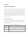
Chapter 4 Design of Feeding Robot ................................................................................................. 48
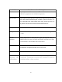
4.1 User Characteristics ............................................................................................................... 48
4.2 User’s Safety ......................................................................................................................... 50
4.3 Assumptions for Using the System ........................................................................................ 50
4.4 Robotic System and Food Tray .............................................................................................. 51
4.5 Cups, Spoon, and Fork........................................................................................................... 51
4.6 Expected Characteristics of Robot ......................................................................................... 56
4.7 Selected Robot ...................................................................................................................... 58
4.8 Adding Cameras to the System .............................................................................................. 60
4.9 Multiple-Users Feeding Procedures ....................................................................................... 62
Chapter 5 ........................................................................................................................................ 78
Kinematic, Dynamic and Control of Multiple-User Feeding Robot .................................................. 78
5.1 Kinematic and Inverse Problem ............................................................................................. 78
5.1.1 Analysis of Manipulator Singularity ................................................................................ 79
5.2 Building Dynamic Equations ................................................................................................. 82
5.3 Robot Control ........................................................................................................................ 83
5.3.1 ADAMS Control ............................................................................................................. 85
Chapter 6 Vision System and Image Processing .............................................................................. 92
6.1 Rationale for the Use of Vision System .................................................................................. 92
6.2 Vision Related Tasks ............................................................................................................. 93
6.3 Image Acquisition and Preprocessing..................................................................................... 94
6.3.1 Image Acquisition ........................................................................................................... 94
6.3.2 Image Histogram ............................................................................................................ 94
6.3.3 Image Enhancement ........................................................................................................ 94
6.4 Processing and Feature Extraction ......................................................................................... 95
6.4.1 Image Thresholding ........................................................................................................ 95
6.4.2 Edge Detection ............................................................................................................... 95
6.4.3 Segmentation .................................................................................................................. 95
6.4.4 Filling the Gaps .............................................................................................................. 96
viii
6.4.5 Region Growing ............................................................................................................. 96
6.4.6 Region Analysis .............................................................................................................. 97
6.4.7 Feature Extraction ........................................................................................................... 97
6.5 Segmenting the Pieces of Solid Food ..................................................................................... 97
6.6 Touching/Overlapping Problem ........................................................................................... 101
6.7 Discussion of Results ........................................................................................................... 103
Chapter 7 Closure ......................................................................................................................... 105
7.1 Observations........................................................................................................................ 105
7.2 Multiple-user feeding system ............................................................................................... 107
7.3 Design ................................................................................................................................. 107
7.4 Vision system ...................................................................................................................... 109
Appendix A Anthropometric Data of an Adult Person ................................................................... 111
Appendix B Research Ethics Review Feedback ............................................................................. 114
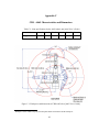
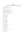
Appendix C CRS A465 Characteristics and Dimensions ................................................................ 115
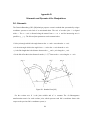
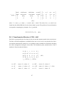
Appendix D Kinematic and Dynamic of the Manipulators ............................................................. 116
Appendix E DynaFlexPro Input Model Generated by Model Builder ............................................. 121
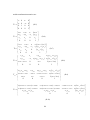
Appendix F Behaviour of ADAMS Model to the Given Motion .................................................... 130
ix
List of Figures
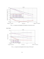
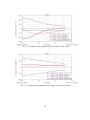
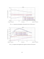
Figure 2-1: Canada’s Aging Population [4]........................................................................................ 6
Figure 2-2: (a) Action Arm [14], (b) Friction Feeder [15] ................................................................ 11
Figure 2-3: (a) Stable Self Feeding Support [15], (b) Comfy Feeder [15] ......................................... 12
Figure 2-4: (a) Eatery [20], (b) Magpie assists in eating [21]............................................................ 13
Figure 2-5: HAND Feeder [21]........................................................................................................ 14
Figure 2-6: My Spoon [23], Beeson Feeder [19] .............................................................................. 16
Figure 2-7: Neater Eater [26] ........................................................................................................... 16
Figure 2-8: Assistive Dinning Device [28] ....................................................................................... 17
Figure 2-9: Winsford feeder [31] ..................................................................................................... 18
Figure 2-10: Mila Feeder [30] ......................................................................................................... 19
Figure 2-11: Handy 1 overall system and food tray [35]................................................................... 20
Figure 2-12: ISAC at work [38] ....................................................................................................... 21
Figure 2-13: (a) The concept of Eater Assist robot, (b) CRT display [41] ......................................... 22
Figure 2-14: Assistive Robot for Bedridden Elderly [43] ................................................................. 22
Figure 2-15: Configuration of Assistive Robot Hand system [44] .................................................... 23
Figure 2-16: Categories of different user interfaces .......................................................................... 31
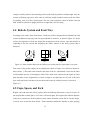
Figure 4-1: Some possible shapes for the food tray (a) circular plate (b) square plate (c) arc plate .... 51
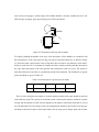
Figure 4-2: Dimensions of the cup and its handle. ............................................................................ 52
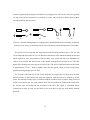
Figure 4-3: Possible feeding angles (a) straight spoon with thick handle for front feeding, (b) inclined
spoon for easier scoop, (c) inclined spoon for semi-side feeding, (d) inclined spoon for side
feeding .................................................................................................................................... 53
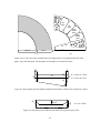
Figure 4-4: (a) Top view of the considered area for fitting utensils, (b) Arrangement of the food
plates, cups, fork and spoon. The directions of all handles are towards the center. .................... 54
Figure 4-5: Deep sloped plate for liquid/semi-liquid foods/desserts which can be scooped by a spoon.
................................................................................................................................................ 54
Figure 4-6: Flat plate for the foods/desserts which can be picked up by a fork.................................. 54
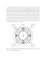
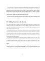
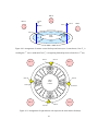
Figure 4-7: Top view of the position and arrangement of four food trays for four users, the users are at
least 25 cm away from the food tray edge. ............................................................................... 55
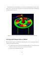
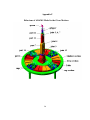
Figure 4-8: 3D model of the robot located in the center of the table along with four food trays. ........ 56
x
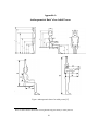
Figure 4-9: Average anthropometric dimension of an adult user [25], size of a typical standard chair
and table, with respect to one food tray and also the proposed robot which has the dimensions of
a Thermo CRS-A465 articulated robot (schematic diagram is to scale, dimensions in mm)....... 59
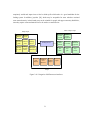
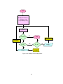
Figure 4-10: Multiple-camera management ..................................................................................... 67
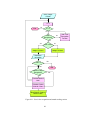
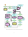
Figure 4-11: User's face recognition and mouth tracking section ...................................................... 68
Figure 4-12: Checking the availability of the users and objects, and object recognition section ........ 69
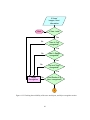
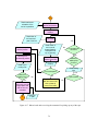
Figure 4-13: Messages sent to the users in case of unavailability of each object ............................... 70
Figure 4-14: Acceptable commands by the feeding robotic system................................................... 71
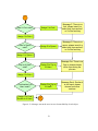
Figure 4-15: Robot's tasks after receiving the command for picking up the fork ............................... 72
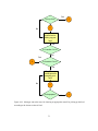
Figure 4-16: Robot's tasks after receiving the command for picking up the spoon ............................ 73
Figure 4-17: Robot's tasks after receiving the command for picking up any of the cups ................... 74
Figure 4-18: Messages sent to the users for choosing an appropriate utensil for picking up the food
according to the chosen section of food .................................................................................... 75
Figure 4-19: Robot's tasks after receiving the command for holding any of the utensils .................... 76
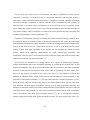
Figure 5-1: 6-DOF robot, inputs and outputs ................................................................................... 80
Figure 5-2: Dynamic model of 6-DOF robot in DynaFlexPro Model Builder in Maple environment 83
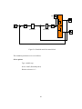
Figure 5-3: ADAMS Model and Control System versus their input and output [ADAMS] ............... 85
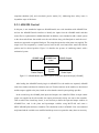
Figure 5-4: The block of adams_sub containing the S-Function ....................................................... 86
Figure 5-5: Defined input and outputs of the model appearing in the sub-blocks .............................. 87
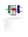
Figure 5-6: Simulink model for control block .................................................................................. 89
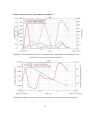
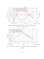
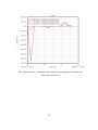
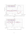
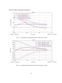
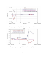
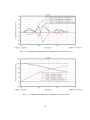
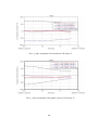
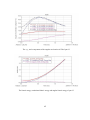
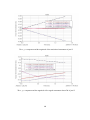
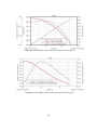
Figure 5-7: Simulation results a) position of the end effector b) output velocity and c) input torque . 90
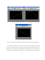
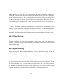
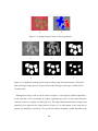
Figure 6-1: a) original image, b) binary image, c) removing small pixels from the edge detected image
3, d) image c after closing with square 3, e) filling gaps of image d, f) image 4 after closing with
square 5, g) filling gaps of image 7, h) segmentation and centroid extraction. .......................... 98
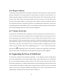
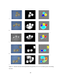
Figure 6-2: Correctly found centroids of image in Figure 6-1-1 ....................................................... 99
Figure 6-3: a) Binary image b) correctly found centroids ................................................................. 99
Figure 6-4: a) Original image b) Error in final segmentation ............................................................ 99
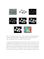
Figure 6-5: a) Original image, b) Error in final segmentation ......................................................... 100
Figure 6-6: a) adjustment of the greyscale image, b) binary image after enhancement, c) filling the
holes of the edge image (square 5), d) first erosion of the filled gaps of the edge, e) fourth
erosion, f) sixth erosion. ........................................................................................................ 100
xi
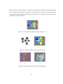
Figure 6-7: Results for some selected possible arrangements (6-7a to 6-7e) of three pieces of touching
cut toast. ................................................................................................................................ 102
xii
List of Tables
Table 2-1: Aging demographics from 1998 to 2041 in Canada [2] ..................................................... 6
Table 2-2: The mean minutes spent for daily activities of elderly with average age of 75.2 -79 [13] ... 9
Table 2-3: Prices of the available feeding devices in the market ....................................................... 24
Table 2-4: Input device familiarity [51] ........................................................................................... 33
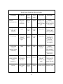
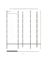
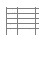
Table 3-1: Observation results of the nursing home of the “Village of Winston Park” senior home .. 37
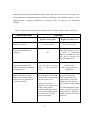
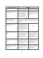
Table 3-2: Different categories of different samples of food, desserts or salads ................................ 42
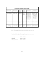
Table 3-3: Percentage of usage of spoon, fork or both in a one week menu ...................................... 44
Table 4-1: Feeding robot user characteristics ................................................................................... 48
Table 4-2: Dimensions of a typical spoon for adults ......................................................................... 52
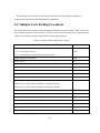
Table 4-3: System variables and reference names ............................................................................ 62
Table 4-4: Acceptable commands from users. .................................................................................. 64
Table 4-5: Functions (subsystems) and the reference names ............................................................. 64
xiii
Chapter 1
Introduction
The goal of this research was to design an intelligent robot, capable of simultaneously feeding
multiple elderly or disabled people sitting at the same table. This feeding robot can be used in senior
homes or similar places where people with upper-limb impairments often eat meals together.
The preliminary research for this project, started with exploration in the broad area of
rehabilitation, with service and assistive robotics in general, for those with upper limb disabilities or
dysfunctions. In addition to workstation robotics in places such as offices and hospitals, different
types of assistive robotics systems were reviewed, including mobile and stationary, attached to and
separate from the body, passively- and actively- controlled, and wheelchair- and table- mounted
systems. This helped to determine the state of the art and potential benefits and problems of
rehabilitation and feeding robots. The first intention was to come up with an assistive device for
upper-limb disabled people that would benefit them in gaining independence in accomplishing daily
activities. In the study, eating was found to be one of the most frequent and time consuming daily
tasks, which would pose many social and emotional problems for the disabled. Since the elderly, as a
population, have the most cases of upper-limb dysfunctions, the intention of the project was directed
more towards developing an assistive feeding machine specifically for them. A parallel preliminary
study aimed at the market analyses of the available feeding machines including their prices, success
rates, features, constraints, and drawbacks was conducted; and knowledge about the demographics
and conditions of potential and existing users of such assistive feeding devices was also acquired.
Consideration of some issues such as available resources, equipment and experience, made the
choice of assistive robotic system more clear; a table-mounted, actively controlled, stationary robot,
not to be used as an extender to any human body part, was ultimately decided upon as the focus of the
design. It was also decided that the robot should be an intelligent one, with the ability to provide a
more convenient and natural user-robot interaction than what is currently available. Since the eating
task was found to be an activity of daily living (ADL) that is repeated more frequently and is more
time-consuming during the week when compared to other daily tasks, the goal of the thesis was
further refined as follows: to design an assistive robotic manipulator to make the elderly as
independent as possible in feeding themselves. Therefore, the thesis literature review only reflects
those devices or machines that assist disabled and/or elderly users with eating and drinking tasks.
1
It was found that the elderly and their feeding requirements in environments such as senior homes
with many elderly residents dining together at least three times per day have not extensively been
researched before. This, the unavailability of multiple-user feeding systems in the market, and the
lack of related research motivated this project to focus on the design of multiple user feeding systems
for nursing homes. The final decision to change the single-user feeding robot to a multiple-user
device was made after a series of observations in an elderly behavioural reactions of the elderly
during meal time in the nursing home, resolved many uncertainties regarding the real needs of this
population in such places while feeding themselves. The user’s characteristics and requirements as
well as some information about the people and environment they were interacting with, such as
caregivers and service-providers in dining areas, were grouped and considered all together. The
outcome of assessing these observations both reinforced the idea about designing a multiple-users
device and solidified the potential benefits of such an assistive machine to make the elderly more
independent.
1.1 Objectives and scope
The objectives of this thesis are to:
1. Review the literature on existing feeding devices for disabled and elderly both in the market
and in the research environment.
2. Determine the end-user and caregiver needs and environmental factors that need to be
considered in the design of a feeding system for elderly by conducting observations of seniors
eating at a nursing home.
3. Perform a preliminary design of a robot system based on the results of the observations at the
nursing home for elderly. The observations led to the initial design of a multiple-user feeding
robot that includes:
a) specifying the robot system and layout in the workspace,
b) determining robot tasks required and their management for multiple users,
c) performing inverse kinematics of the robot system to determine the robot joint angles
based on the end-effector position,
2
d) performing image processing to recognize and locate solid food parts as an initial
development of vision-based robot interface for feeding purposes.
The layout of this thesis is as follows: Chapter 2 presents a literature review of previous and current
research attempts to design an assisting device to help the elderly or disabled with feeding
themselves; it also analyzes the existing market and reviews the available user interfaces utilized by
feeding machines or similar rehabilitation or service robots. Chapter 3 reveals the objectives and
results of a series of observations in a nursing home. The listed characteristics of the typical users and
specifications of the desired robot are based on the outcomes of these observations. Chapter 4
introduces the design of a feeding robot, including a robot manipulator and food trays and their
dimensions. Chapter 5 reviews the kinematic, dynamic and control issues of the proposed feeding
robot. It assigns the coordinate systems, defines Denavit-Hartenberg (DH) parameters and tables,
calculates the transformation matrices for each joint and finds the Jacobian matrix and singular
positions. The inverse kinematic analysis is provided along with the preliminary steps for controlling
the robot using ADAMS software. Chapter 6 explains the vision system and image processing for
recognition of some types of food inside the tray. This chapter shows the results of processed images
by the developed algorithm for segmentation of the pieces of solid foods inside the food tray and
finding the best insertion point for the fork. Finally, Chapter 7 concludes the project and highlights
plausible future directions of research that would complement the present study.
3
Chapter 2
Literature Review
The most important goals of this chapter are to review previous and current research attempts to
design assistive feeding devices and their user interfaces, and to perform a market analysis by
introducing similar products available in the existing market for use by elderly and disabled people
with any kind of upper-limb dysfunction. However, before presenting such a review, the issues of a
rapidly increasing elderly population, the escalating problem of their required personal and public
services, and different kinds of diseases which may lead to disabilities of upper-extremities are
discussed. This discussion will reflect the importance of designing assistive machines, rehabilitation
or service robotic systems for this population to use in different environments.
One of the important issues in designing assistive devices is laid on the demographics of their
users. The statistical data regarding the number and characteristics of the user population plays an
important role in motivating the continuation of such projects, as well as determining the design
limitations to be considered and necessary features to be added to the system. The next section
introduces the objectives of the market analysis for the feeding device and lists important issues that
will be discussed in the next sections.
2.1 Marketing
The objective of marketing is to understand both the market itself and the requirements of consumers
in order to be able to identify the design constraints of the proposed product and its price. In
rehabilitation and service robotics, many good designs have failed because of basic design flaws, such
as cost, ergonomics and difficulties in utilizing controls. Therefore, it is critical for a designer to
determine the user requirements as well as the design limitations beforehand.
One of the most important parts of analyzing the market for an assistive feeding device is the
needs analysis. The needs analysis looks at the statistics and studies about the people who are in need
of such devices. Furthermore, major criteria such as age, type of disability, gender and income level
4
of the users are important in the design considerations; and the priorities may be different based on
whether the user lives in an institution, with a family member, or independently with a caregiver to
assist in the activities of daily living (ADL).
Some of the issues to be discussed in the upcoming sections of this chapter are: 1) the number and
characteristics of people in need of assistive devices (demographics of the potential users), 2) the
demographics of existing consumers of available products (existing user demographics), 3) causes of
upper limb disabilities of the users and consequent dysfunctions in ADL, specifically with respect to
the elderly, 4) physical and mental capacity of the consumers to operate the device, 5) available
assistive devices in the market for people with difficulties using any part of their upper-extremities, 6)
previous and current related research projects that have been attempted or reached completion, 7)
features, constraints and prices of available products and useful applicable information; and results
from previous and existing research relevant to this project, 8) available user interfaces specifically
for feeding devices and similar rehabilitation devices in general.
Since the majority of the potential users of the proposed feeding system are elderly, 65 years of age
or older, the following section attempts to convey the fast growing problems of aging for today and
the future.
2.2 Aging Population and Escalation of Required Services
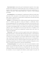
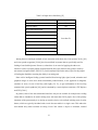
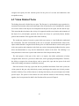
Older adults are the fastest growing group in North America, Europe, and Asia [1]. As
demonstrated in Table 2-1 [2], which shows the number of Canadians over age 65 as a percentage of
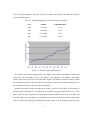
the total population, by 2016, almost 16% of all Canadians will be aged 65 and over. In addition,
Figure 2-1 [4] demonstrates the increasingly fast rate of growth expected of the Canadian elderly
population in the future compared to just a few years ago. The United States also expects a dramatic
increase both in number and proportion of the elderly population [3]. The rate of occurrence of
disabilities increases as age increases, which means that as people get older they are less active and
need more assistance. Canada has the highest rate of institutionalization of elderly citizens in the
world [5]. Almost 10% of Canadians over the age of 65 are living in long-term care institutions
because they can no longer safely care for themselves. The increasing number of elderly people in
conjunction with the increasing frequency of their disabilities will have a big impact on the future of
healthcare systems, as it will be necessary for them to make adjustments in order to provide adequate
5
services for this population. The next section will discuss some aspects that affect the required
services of elderly people.
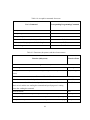
Table 2-1: Aging demographics from 1998 to 2041 in Canada [2]
Year
Number
Population share
1998
3.7 million
12.3 %
2016
5.9 million
15.9 %
2021
6.9 million
17.8 %
2041
9.7 million
22.6 %
Figure 2-1: Canada’s Aging Population [4]
The focus of most national aging policies is on dignity, independence, participation, fairness and
security [6], since the quality of life of the elderly is very important. Consequently, older adults
require a huge share of special services and public support. The number of persons requiring formal
care (mainly nursing home care) and informal care (mainly care at home) will increase sharply even if
the proportion of persons at each age remains unchanged.
Another issue that will affect providing the necessary services for the elderly is the number of
available nurses and caregivers. A study about the workforce of aging registered nurses [7] reveals
that: a) within 10 years, 40 percent of working registered nurses (RNs) will be 50 years or older; and
b) as those RNs retire, the supply of working RNs is projected to be 20 percent below requirements
by the year 2020. This shortage of employed nurses and caregivers in the coming years will provide
6
significant opportunities for robotics and artificial intelligence (AI) researchers to develop assistive
technology that can improve the quality of life for the aging population. [8]
2.3 Self-Feeding Disabilities
In order to assess the demographics that would benefit from assistive devices, specifically for feeding,
one would typically look to the statistical data available for populations with disabilities in general
and the elderly specifically. Unfortunately, there is great variation in the incidence of disabilities in
the statistics from different countries. These differences may be caused by different reporting criteria,
degrees of industrialization, rate of accidents, or participation in wars. Statistics for senior populations
seem to be more telling, as the proportion of seniors in the general population of developed countries
is higher than in underdeveloped countries. Also, almost 75% of the elderly (aged 65 and over) have
at least one chronic illness and 50% have at least two chronic illnesses [9]. Chronic conditions can
lead to severe and immediate disabilities, as well as progressive disabilities that slowly erode the
ability of elderly people to care for themselves [10].
In general, some of the neuromuscular diseases which cause any disability or dysfunction in the
upper-extremities may hinder the typically easy procedure of eating or make it a very difficult task to
accomplish. The disabilities that lead to upper-limb disabilities are: Essential Tremor, Parkinson,
Dementia/Alzheimer, Stroke, Spinal Cord Injury (SCI), Multiple Sclerosis (MS), Cerebral Palsy (CP),
Spinal Muscular Atrophy1 (SMA), Muscular Dystrophy (MD) and Amyotrophic Lateral Sclerosis
(ALS) [11]. But among these, the first four are more common among the elderly.
Those with essential tremors [12] have difficulty eating normally or holding a cup or glass without
spilling it, and if the voice or tongue is affected, difficulty in talking may occur. Parkinson [11], [12]
which affects muscle movement nerve cells, causes tremors of the fingers and arms, muscle rigidity in
the limbs and neck, slowed motion, impaired speech, loss of automatic movement, difficulty chewing
and swallowing and also problems with movement balance and coordination. Dementia and
Alzheimer’s disease [11], [12] can cause a decline in memory, comprehension, learning capability,
and ability to think, as well as language and judgment. People suffering from this kind of disease may
see food on their plate, but they cannot logically connect hunger to food to feeding.
1
Atrophy: A wasting of a part of the body because of disease or lack of use. [Wikipedia Encyclopedia]
7
Furthermore, people with SCI may have tingling or loss of sensation in their hands, fingers, feet, or
toes; partial or complete loss of control over any part of the body; and difficulty with balance. Those
with MS may experience coordination and memory problems, blurred vision, muscle spasticity,
indistinct speech, tremor, weakness and swallowing disorders. MD, on the other hand, is a muscle
disorder that causes weakness and wasting of the voluntary muscles that are responsible for
movement of body parts. Similarly ALS is a disease of the motor nerve cells in the brain and spinal
cord that causes those afflicted with it to have muscle weakness, twitching, cramping and stiffness of
muscles, slurred speech, and difficulty chewing or swallowing.
In general, an elderly person with limitations of vision, hearing or mobility can be made more
independent if the deficits are properly assessed and the environment appropriately designed. The
prevalence of sensory changes and injuries among the elderly dictates the importance of addressing
them in primary care settings. The elderly individual’s perception of the environment changes subtly
as the senses age. Changes in vision, hearing, taste and smell are almost universal. Only 5% of
persons over 80 have 20/20 vision, and nearly 60% of those aged 65 to 70 show evidence of cataracts
or glaucoma. Twenty-five percent of those over 65 have some type of hearing problem and among
persons over 75, the incidence increases to over 40%. Sixteen percent of the elderly report they can
hear only shouted speech. Similarly, the thresholds for taste and smell increase with age [12].
Lower frequency, lower pitch and tone of voices, an increase in sound threshold, especially for
high-pitched sounds, a decrease in speech discrimination and auditory judgment are some of the
typical characteristics of the elderly group. They are also more susceptible to eye diseases and having
vision problems [4]. They usually have difficulty in reading small print; have poor vision in
environments with insufficient light and need longer adaptation time to light changes.
Sensory losses, especially for the older population, limit self-care and activities of daily living, and
significantly alter communication and interaction patterns [4]. Impairment of the senses contributes
considerably to the decline in functional state of the elderly individual and leads to their increasing
isolation. The sensory impairments of the elderly, such as partial to complete loss of the ability to
hear, talk, or see will have the effect of decreasing their functionality in conducting everyday tasks.
The above analysis makes clear that, as with any new technology, it is important to consider the
characteristics of the users who will benefit from it before designing a new assistive device. Indeed,
the proportion of seniors with upper extremity disabilities, the cause of and physical manifestations of
8
those disabilities, as well as the natural degradation of sensory perception that may alter the
functional abilities of the elderly are all important considerations in the design of an assistive eating
robot.
2.4 Eating As a Daily Activity
Among the total everyday obligatory activities for the elderly, eating is the most time consuming.
Based on the study of Moss and Lawton in 1982 [13], the mean minutes spent eating in a 24-hour day
for impaired residents averaging in age from 75.2 to 79 was 77 minutes, whereas the time spent for
other daily tasks such as personal care or health care, shopping, housework or home maintenance, and
cooking was noticeably less (see Table 2-2 for the average time spent on typical daily tasks by the
elderly). It is obvious from Table 2-2 that having any difficulty in accomplishing eating tasks will
have a great impact on the social behaviour of elderly individuals.
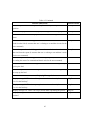
Table 2-2: The mean minutes spent for daily activities of elderly with average age of 75.2 -79 [13]
Daily Task
Spent Time (Minute) for Impaired Residents
Eating
77
Shopping
22
Personal/Health care
71
Housework/ Home maintenance
68
Cooking
69
The next section introduces different types of assistive feeding devices which are either
manufactured and available in the market, or are still in the research phase and have only been
designed or prototyped.
2.5 Available Feeding Devices
Currently, the numbers of research areas that are finding ways to support those with upper limb
disabilities to independently accomplish their various activities of daily living (ADL)- are growing.
One part of this vast research area is focused on providing facilities for eating and drinking, preparing
food, going to the bathroom, bathing, and getting dressed. These assistive devices have the potential
9
to not only increase self-esteem, confidence in accomplishing ADL tasks and independence, but also
to decrease the number of caregivers and institutional costs required to adequately care for this
population.
The desire to assist in feeding those with upper limb disabilities or dysfunctions with a machine or
robot, in an effort to help them accomplish their eating tasks independently, has been capturing the
minds of many researchers and designers for decades. Whether the devices are simple mechanical or
electromechanical machines or complicated, intelligent robots, gaining independence in ADL has
been the major motivation behind their development.
Using different human–machine interfaces, from simple switches activated by different body parts
(depending on type of disability), to more advanced ones, such as voice and speech recognition and
synthesis, laser pointing devices, object recognition and computer vision, researchers have tried their
best to accommodate the needs of users, patients, and elderly persons who have expressed the desire
for an assistive device that not only helps them eat more easily and neatly, but is both safe and
comfortable to use, and will allow them to minimize their dependence on nurses, caregivers or family
members. Some of the proposed and commercially available assistive feeding systems will be
mentioned in the following sections. These devices have been categorized as: arm supports, human
extenders, electro-mechanical devices, and intelligent automatic or semi-automatic machines.
2.5.1 Arm Supports
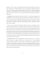
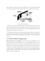
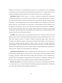
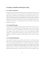
Action Arm: Action Arm, distributed by Flaghouse Inc. [14], is designed for use by individuals with
neurological or upper extremity disabilities or spinal cord injuries. This device, shown in Figure 2-2
(a), includes multiple joints, like the human arm, that provide a variable repetition and kinesthetic
feedback (feedback that helps to detect bodily position, weight, or movement of the muscles, tendons
and joints). The unit, which has a flexible mounting system, is equipped with an adjustable resistance
and range of motion, and a stylus (sharp, pointed tool) that can adjust to hold writing or eating
utensils.
Friction Feeder: Friction Feeder [15] is made for users suffering from spasticity (having
involuntary contraction of a muscle or group of muscles), mild tremors, ataxia (loss of the ability to
coordinate muscular movement) or mild-to-moderate uncoordination.
10
(a)
(b)
Figure 2-2: (a) Action Arm [14], (b) Friction Feeder [15]
It helps in leading any inappropriate movement of the shoulder and elbow to the correct direction, and
assists in self-feeding and leisure activities. Bands are used to aid control of horizontal shoulder
abduction (drawing away from the midline of the body) and adduction (drawing inward toward the
median axis of the body), and flexion and extension of the elbow. (Figure 2-2(b))
Ball Bearing Feeder with Elevating Proximal Arm: The Ball Bearing Feeder [15] is a balanced
forearm orthosis designed as an arm support for feeding those with shoulder weakness. The device,
which can be clamped to most wheelchairs, consists of a metal arm trough with free swinging arm
support and a ball bearing joint.
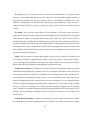
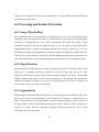
Stable Self Feeding Support: Stable Self Feeding Support [15], represented in Figure 2-3(a), guides
the arm as it moves from plate to mouth. It provides a support for the forearm and allows it to move
into the smaller top section with a simple sliding motion. This gives stability and support, while
bringing food to the mouth. The roof attachment helps to keep the arm on the slide and provides
additional control and support.
Comfy Feeder: Comfy Feeder [15, 16] helps individuals with Multiple Sclerosis, Parkinson’s
disease, Cerebral Palsy, other neurological conditions, and those with generalized upper extremity
weakness, feed themselves by allowing them to guide an attached spoon through a food-pick-up
sequence. A gas-spring level damper absorbs tremors and jerky movements; and the self-levelled
spoon eliminates messy spills and ensures horizontal positioning from the bowl/dish to mouth. The
spoon and pivot assembly, shown in Figure 2-3(b), can be attached to operate either in, or at a right
11
angle to the plane of the arm. It has a rotating platform on a non-slip baseboard. Since the user only
controls the eating process, no external power source is used.
(a)
(b)
Figure 2-3: (a) Stable Self Feeding Support [15], (b) Comfy Feeder [15]
Stable Slide: Stable slide [17] is an arm support designed to provide support during the activity of
self feeding for individuals with tremors, limited strength, or motor control disabilities. The portable
device can be clamped to tables, is fully adjustable both in height and angle, and is available for both
right and left handed individuals. Since it doesn’t have the ability to move the user's arm, it is not
appropriate for those with paralysis or severe weakness.
The next section introduces assistive feeding devices called teletheses, which attach to a human
body part, such as the head, leg or foot. They are passive mechanisms that act as an extension of the
person and rely on the remnant functional musculature of the coupled body part to transform its
motion into a usable motion of an end effector such as a spoon or fork. These mechanisms take
advantage of extended physiological proprioception (EPP)2 to use direct feedback control from the
users to operate the simple device with flexibility and reliability [18].
2
EPP: Extended Physiological Proprioception describes the ability to perceive at the tip of the tool such as a
human extender or a prosthetic limb. {Wikipedia Encyclopedia]
12
2.5.2 Human Extenders for Feeding
Eatery: Eatery, manufactured by Do It Yourself and available at Maddak Inc [19], is a nonarticulated device that allows bilateral upper-limb amputees to eat independently without prostheses.
The plastic tray has three compartments and a height adjustable plastic-coated stand. The front of the
tray, as shown in Figure 2-4(a), has two spoon-like projections; and the user uses their mouth to
directly take food off the tray at this projection by use of the head piece. The device requires the user
to have some trunk movement and good head control, which is a limitation since people with neck or
spinal cord injuries may not be able to benefit from it. However, these simple devices would be ideal
for non-prosthesis users that are in otherwise good physical condition. The lightweight headpiece is
adjustable and padded for a comfortable fit. The modified spoon and plastic tray are removable. The
headpiece can be used as a pointer if the spoon attachment rod is replaced with a head pointer rod.
Magpie: Magpie [21], represented in Figure 2-4(b), is a purely mechanical, leg operated,
wheelchair-mounted, low cost, assistive device which is designed and manufactured at the Nuffield
Orthopaedic Center in Oxford, England. It can help users not only with feeding, but with other tasks
such as typing, turning pages, and shaving. It has the advantage of providing the user with continuous
feedback by virtue of the direct coupling of the end effector of the feeding device and the human
joints (human legs in the case of Magpie). Its limitation is that it can only be used for those who are
able to move their legs but not their arms. Therefore, people with spinal cord injuries would be unable
to benefit from it, since they are often unable to move their legs as well as their hands.
(a)
(b)
Figure 2-4: (a) Eatery [20], (b) Magpie assists in eating [21]
13
HAND Feeder: Head Actuated Nutritional Device (HAND) [21] is a passive, head-controlled
feeding device for quadriplegics. The mechanism, shown in Figure 2-5, is like a telethesis, coupled to
the user’s body part and acting as an extension of the person. The virtual model of the feeding
mechanism, developed at the University of Pennsylvania, is shown in Figure 2-8. This 3-DOF passive
mechanical feeder driven by cables uses head and neck movements to control the movement of a
spoon. The head yaw movement causes the linkage to rotate about a vertical axis and translate in a
horizontal plane to keep the spoon in the line of sight of the user.
Figure 2-5: HAND Feeder [21]
The head pitch movement causes the spoon to perform a planar motion that involves scooping up
the food and bringing it up to the mouth. The head roll movement causes the spoon to pitch about a
transverse axis [21]. It transforms the user’s head motion into a usable motion of the end effector
such. One of the limitations is that it can only be used by those quadriplegics who have control of
their neck. It also consists of a 6-DOF user input subsystem and a 3-DOF end-effector subsystem,
which makes it very bulky for individual use and requires considerable of space.
The following section introduces the electro-mechanically powered devices that use an electrical
power supply to activate the machine.
2.5.3 Electro-Mechanical Powered Devices
University of Illinois Feeding Mechanism: The feeding mechanism developed at the University
of Illinois (Urban-Champaign) was custom designed for a student with physical and mental
14
disabilities. It used a Compact Carriage Mechanism (CCM), utilizing the interaction of three shafts,
three tension springs, a rotational damper, and two cams to produce the optimum motion of the
utensil. The device consisted of a mechanism enclosed within a PVC case, a spoon that is detachable
for cleaning, a specially designed bowl, a pad switch for user input and a 12V DC power supply that
plugs into a wall outlet. The device was not commercialized and the spoon had limited degrees of
freedom. [22].
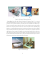
My Spoon: My Spoon, manufactured at Secom Co Ltd [23], is a powered feeder designed for use
by individuals with spinal cord injury, upper extremity disabilities, or amputation, which allows users
to eat most types of everyday food with minimal help from a caregiver. A base unit, shown in Figure
2-6(a), sits on the table next to a dish with four compartments. The device can operate in manual,
semi-automatic, or automatic modes, with a joystick, button switch, or combination of joystick,
button or switch controller.
There is no vision system for food recognition. Therefore, it is the user’s responsibility to choose
the desired food and direct the arm, by interacting with the machine through a laser pointing system.
The user operates the robot only by head movement to point on the up/down/right/left/back and forth
buttons on the panel to move the robot arm in the required location and orientation. After the food is
removed from the spoon, the robot arm returns to the home-position automatically. Application of the
non-contact sensor and emergency switch did not work on this device for safety reasons, because of
low reliability of the sensor in defending the user and inability of a disabled person to quickly operate
the emergency switch. However it has been stated in [24] that the light weight of the robot arm and its
low speed ensures the safety of the user.
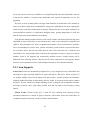
Beeson Feeder: Beeson Feeder from Maddak Inc [19], shown in Figure 2-6 (b), is for persons
with severe physical or cognitive limitations due to cerebral palsy, SCI, or other impairment
involving movement, coordination, or range of motion. One control operates a spoon to take food to
the mouth level and the other one rotates the plate to keep the food properly distributed for the spoon
to pick up. The user should be cognitively aware of the cause and effect of the two-switch operation,
have two consistent points of motor control for switch activation, and the ability to move the body or
head forward to take food off the spoon.
15
(a)
(b)
Figure 2-6: My Spoon [23], Beeson Feeder [19]
Neater Eater: Neater Eater from Therafin Corporation [25], shown in Figure 2-7, is a powered
feeder with programmable arm. The device can be set up for five different diners, but only one diner
can utilize it at a time, and the automatic cycle of the spoon can be controlled in four different ways.
The user can control the spoon or plate cycle with one or two switches that can be pressed with the
hand or knee. It keeps the spoon level as the arm is moved. In a manual version, adjustable springs
help the user to smoothly guide the spoon down into the plate, and back up to the mouth. Adjustable
stops prevent the spoon from moving past the plate or too close to the user, and stop the spoon at the
right height for the user's mouth. In an adapted version, the adjustable handle allows the spoon to be
used with relatively small movement of the user's hands. A plate-turner wheel allows the user to turn
the plate without lifting their hand from their lap. Tall spacers underneath the base help to reduce the
distance the spoon has to travel from the plate to the user's mouth.
Figure 2-7: Neater Eater [26]
16
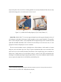
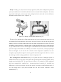
Assistive Dining Device: Assistive Dinning Device from Mealtime Partners Inc [27] is a powered
feeder that has rotating bowls, a mechanical spoon, and a positioning arm. The bowls rotate until the
desired food is located under the spoon. To avoid mixing, each food is contained within a single
bowl. (Figure 2-8) It can hold up to three bowls of food at one time, each of which holds one cup.
Three general modes of operation are: 1) fully automatic, 2) using one adaptive switch, and 3) using
two adaptive switches. The feeder can be set to operate with numerous combinations of rotational
speed, length of time the device pauses to allow the user to take food from the spoon, minimum dwell
times for the switches, and time settings for spoon retraction after user contact. The operation is done
with the help of a control panel.
Figure 2-8: Assistive Dinning Device [28]
Winsford Feeder: The Winsford feeder [31], shown in Figure 2-9, is a single-purpose feeding aid
which enables individuals to feed themselves independently from a standard dinner plate or bowl. It is
controlled by either a chin switch or other types of switches. The height of the feeder may be
adjusted, but the user should have stable head and trunk control. Food preparation and feeder setup is
performed by an attendant.
A rotating plate lets the user pick up food from any location on the plate by the help of a pusher for
placing the food on the spoon. If the amount of food is too little, the plate and pusher may be
activated again to add more food to the spoon; and if it is too much, it may be returned to the plate
and emptied. A cup holder is included to hold drinks that are normally accessed with a straw; and a
drip pan and shelf prevents food from spilling on the user.
17
Figure 2-9: Winsford feeder [31]
Automatic Feeding Device: The automatic feeding device from Sammons Preston Rolyan [18] is
a battery operated feeder. The speed and sequence of operation is controlled by a chin switch. It has
some features such as an adjustable height stand, spring supported spoon and remote switch for the
hand or foot, but it requires sufficient head control to push the switch and to position the mouth at the
spoon location.
Electric Self-Feeder: The electric self-feeder, made at Sammons Preston Rolyan [15], is a batterypowered feeder which assists disabled people in eating meals at their own speed. A slight head
motion on the chin switch activates the motorized pusher to fill the spoon and then automatically
moves it to the mouth. The rotation of the plate is controlled for food selection. A bowl may be
substituted for the plate by removing the plate and pusher and adding the turntable, shelf, and drip
pan. The height can be adjusted. The feeder includes a removable hand or foot control for individuals
who are unable to operate the chin switch.
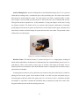
Mila One-Step Electrical Feeder: The Mila Electric Feeder, manufactured by Mila Medical
Company [29] and shown in Figure 2-10, is activated by hand, arm, shoulder or head in one simple
motion. By pushing the padded bar, it lowers a spoon to scoop food while a plate mechanically rotates
to a new position. The base, push bar, and aluminium bar support a detachable spoon, plate and cup
holder. This simple device needs the least physical control and can be activated by one’s head or
other parts of the body to scoop the food and automatically rotate the plate. It is adaptable to both
18
adult and children sizes and also various types of disabilities. The users have complete control and
can eat at their own speed. One of the limitations of the device is its dependency on a power supply.
Figure 2-10: Mila Feeder [30]
More advances in robotic related technology and also the limited control of the user over the
machine in electro-mechanical feeders led the designer to develop a more intelligent assistive feeding
system [32]. Although there are many commercially available non-intelligent feeding devices, the
intelligent systems are mostly in the research state.
The following section introduces some of the robotic feeding systems which are mostly articulated
serial manipulators, fully automatic and actively controlled. Some of them use an intelligent user
interface, such as vision system, speech recognition or speech synthesis, to provide more autonomy
for the users.
2.5.4 Assistive Robotic Feeding Systems
Robotic Feeding Device for Quadriplegics: A robotic feeding device for quadriplegics [33] was
designed at the University of Alberta, Canada in 1983. It was a programmable robotic arm, with 5
revolute joints and 5 motors in each joint, and was designed specifically for feeding the severely
disabled. The cost of mechanical parts and transducers was claimed to be reduced by using the device
in learning mode, by manually forcing it through the desired motion and also utilizing the transducers
to track the motion. The electromechanical driving devices were used as angular displacement
transducers. The motor can only be used as either a motor or as a measuring transducer at one time.
This was one of the system’s drawbacks.
19
Handy 1: Handy 1 [34, 35] was one of the early approaches (1987) to an intelligent eating assistant
system (not attached to the wheelchair) that has also been successful in the marketplace. Since then,
people with cerebral palsy, motor neuron disease, multiple sclerosis, stroke and also the elderly have
benefited from this assistive device. (Figure 2-11)
Figure 2-11: Handy 1 overall system and food tray [35]
The ease of use, requiring only a slight touch from the user in order to operate the system, low cost
and aesthetically pleasing appearance have made it successful. It helps the user not only in eating and
drinking, but also in washing, brushing their teeth and make up application for women. The eating
and drinking system consists of a scanning system of lights that allows the user to select food from
any part of the dish. The user waits for the light to scan behind the desired column of food and then
presses the single switch which sets the Handy 1 in motion. Two years later, a unique input/output
board was designed to slot into the PC controller which incorporates capabilities for voice
recognition, speech synthesis, inputs for sensors, joystick control and stepper motor drivers, to ensure
that the design could be easily upgradeable for future developments [35].
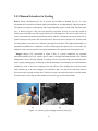
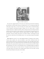
ISAC (Intelligent Soft Arm Control): ISAC [36- 38], from the Center of Intelligent Systems in
Vanderbilt University (1991), used a vision system and speech recognition to interact with the elderly
through natural commands [36]. The system, shown in Figure 2-12, contained a 5-DOF manipulator
which was pneumatically controlled by a microprocessor-based controller. It benefited from
Rubbertuator, which was a pneumatic actuator that operated in a manner resembling human muscle. It
was light weight, had a high power-to-weight ratio and had inherent compliance control
characteristics [37].
20
Figure 2-12: ISAC at work [38]
The system was equipped with three CCD cameras, one located on top of the table for monitoring
the food and two in front and side of the user to monitor the user’s face. An image processing board
could capture images from up to four CCD cameras. The control software was distributed among
several workstations interconnected through an Ethernet LAN. For safety reasons, a collision
avoidance subsystem was added to the whole system by utilizing real-time face tracking and motion
prediction and reactive/predictive motion planning. Face tracking planned the approach path to the
face and helped in collision prediction/ detection. Motion prediction was added to enhance the
performance of the face tracking system and also for collision avoidance. Considering the fact that
this robot arm could feed only one individual person, it was very bulky and required considerable
space.
Eater Assist: Eater Assist [39- 41], from Kanagawa Institute of Technology, Japan, utilized a
Cartesian robot to handle, move, rotate, and withdraw a spoon. With a head space pointer and
personal computer display the user could control and operate the system with either head movement,
blowing into a tube or by selecting direction/location commands listed on the PC display located in
front of them. The system provides two options to the users to move the robot arm on CRT (CathodeRay Tube) display. One is the use of various defined icons on a CRT display that has been assigned to
a specific movement of the arm, for instance the letter U for upward movement. The other is the use
of an image from the CCD camera. In the example shown in Figure 2-13(b), the robot is moving
towards the specified point on the picture (such as mouth).
21
(a)
(b)
Figure 2-13: (a) The concept of Eater Assist robot, (b) CRT display [41]
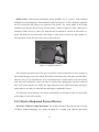
Assistive Robot for Bedridden Elderly: The Kanagawa Inst. came up with another assistive
device that is used for bedridden elderly people to help them with handling drinking cups, and picking
up their belongings from unreachable locations. The user would use the laser pointing device to
communicate with the robot. [42,43]. As shown Figure 2-14, the robot is a Cartesian robot with a
hanging arm above user’s head that can move toward the specified object location selected by a laser
pointing device.
Figure 2-14: Assistive Robot for Bedridden Elderly [43]
22
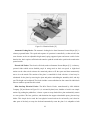
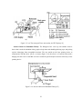
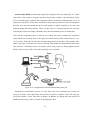
Assistive Robot Hand: A robot hand, designed at Yamaguchi University, Japan [44], is a 5-DOF
robot with a vision system to recognize and detect the positions of dishes, cups and utensils (Figure
2-15). It includes speech synthesis and recognition software for bilateral communication in case of
image processing failure. Some of the limitations of the proposed system are based on assumptions
about the users and environment that do not work properly in public situations or for users with
limited speaking and hearing abilities. That is, for this system it is assumed that the user can speak
well enough to select some simple commands. Also, the reconfirmation process is cumbersome.
Every time the recognition process is done for every object, the system reconfirms the recognition
result with the user by asking if this is the object (for instance the first dish) and then waits for “yes”
or “no” answer. It does this for all of the existing feeding utensils on the table. If the position of the
object is not right, it also asks how it can be corrected. This method of communication between the
robot and user is absolutely useless for locations where many people are dining together and the
abilities of the user to provide a clear and recognizable voice is limited.
Figure 2-15: Configuration of Assistive Robot Hand system [44]
Although the reconfirmation process for each object and vocal command may increase the
accuracy of results, it also significantly increases the time taken to complete a task. This time may
exceed the patience of users when they are hungry. In addition, no strategy has been specified to
handle the task of using a fork as a utensil for picking up the food.
23
Food Tray Carry Robot: People with difficulty in moving their arms can actuate the Food Tray
Carry Robot [45] with very little force applied by a finger. The robot arm is a lightweight
manipulator, set on the floor beside the patient’s bed.
Strain gauges installed in a man-machine interface that is attached to the robot’s tip, can detect the
force applied to the operation plate. The parallel link system in the radial direction has been used to
keep the food tray even with the ground. Therefore, no actuator or control system is required to
maintain the horizontal plane of the food tray.
The next section lists the prices of some of the previously mentioned feeding devices that have
made it to the marketplace. Prices are not available for all of the aforementioned devices, largely
because some have not yet been commercialized and others are still in the research phase of
production.
2.5.5 Prices of Feeding Devices
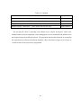
The costs of some of the available non-intelligent feeding devices are presented in Table 2-3.
Table 2-3: Prices of the available feeding devices in the market
Feeding Assistive Device
Price
Action arm [14]
$149.00 (US)
Assistive dinning device [28]
$7995.00 (US)
Mila One-Step Electrical Feeder [46]
$300.00 (US)
Friction Feeder[15]
$473.95 (US)
Comfy Feeder [15,16]
$510.95 (US)
Neater Eater Manual Version [25,26]
$2,149.95 (US)
Neater Eater Electric Version [25,26]
$ 3,795.95 (US)
Neater Eater Adapted Model (Left or right hand) [25,26] $2,695.95
Magpie [46]
$1,750.00(1987)
Winsford Feeder [15]
$3,745.95 (US)
Handy 1 [34, 35]
£3950.00 (UK) (1996)
24
2.5.6 Discussion on Feeding Devices
The review of different available feeding devices reveals that most of them are specifically designed
for the purpose of home use by one individual person. There was no multiple-user feeding device
available in the market. The complete review also reveals that attention has not been paid to
environments outside the home either in the market or in research. The importance of environments
such as senior homes for the elderly and their consequent difficulties motivated this idea of designing
a special feeder for people in this environment.
The next section introduces some of the input and output devices and methods for sending
commands to the machine and releasing information to the users, respectively. Then the
appropriateness of each, with respect to its use in feeding devices, mostly for the elderly, and in
public dining areas such as senior homes, is discussed.
2.6 User Interfaces for Feeding Devices
An important factor to determine the success or acceptability of a service robot relates to the
physiological aspects of implementing techniques for human-robot interactions in unprotected and
unstructured environments [47]. Discussed in this section are possible robot interface devices that can
be applied in a dining environment in a way that can be beneficial for people with upper-limb
disabilities or dysfunctions. A user interface makes it possible for users to interact with robotic
systems in a natural and convenient way. The ability of each user interface to be applied to a multipleuser feeding device will be discussed separately.
The following section introduces different user interfaces that have been used so far in
rehabilitation devices and systems and that have the potential to be applied to feeding machines.
2.6.1 User Interfaces for Rehabilitation or Assistive Devices
The usefulness of robotic devices is largely dependent on the degree of independence which they
provide to their operators [48]. Shortcomings in the user interface can act as major restrictions to the
widespread use of the robotic systems in human service [49]. Human factors guidelines [50] for user
interface design suggest to design it: 1) for ease of use, 2) to enhance user productivity, 3) to reduce
stress on the user, and, 4) for ease of learning. The following sections introduce and summarize
25
features and drawbacks of different possible and available user interfaces for interaction of the user
with a robot or a machine.
Button or Switch: A button is an easy to use input device which is able to enter just a single
command. It needs both a pushing force and a pushing device (finger, or simple stick attached to the
head/chin). For use with the elderly, buttons should be big, with big printed labels, and should require
as little activation force as possible, especially for users with weak muscles.
A switch is also a simple and reliable input device which is able to be in the state of on or off to
provide a single command, and can be issued by almost any body part, such as a hand, head, chin, or
shoulder.
Blow-Activated Switch: Blowing into a tube may be used as an option for clicking a mouse. As its
name suggests, it uses the power of blown air from the mouth instead of fingers; and the pressure of
the air may be transferred via a tube [39-43]. It may be suitable for users with severe upper-arm
disabilities who do not have breathing problems.
Bite-Activated Switch: Biting on a pressure sensor may also be used as an option to replace
manually clicking a mouse. It may be suitable for users with severe disabilities of the upperextremities, whose jaw muscles are functional and who can close their mouth and generate varying
degrees of bite pressure. This interface has been used in Chameleon [53], which is a body-powered
rehabilitation robot.
Foot-Activated Pedal: Typically used in seated positions, a foot activated pedal is a simple
interface which uses the force of the foot to move a robot arm. Foot movement information may be
transferred to the robot arm by way of cables. This is an appropriate device for those who have
enough ability in and control of their legs and feet, and want to have control on the robotic arm by
themselves.
Joystick: A joystick is an input device for controlling forward, backward, upward and downward
movements. It provides an easier grasp than a standard mouse for those who have grasping problems.
Some assistive devices such as wheelchair-mounted robots, Manus [52] and My Spoon [23], are
equipped with this device as an optional interface. However, people with cerebral palsy, stroke
patients who omit stimuli from one side, and quadriplegics may be unable to make fine movement
corrections necessary to use a standard joystick [51].
26
Touch Sensitive Panel: A touch sensitive panel is another button-free input device. It has a single,
solid-state sensor pad that can be activated by human touch. There is no membrane to tear, crack or
degrade over time; no moving parts to wear and potentially fail; and no need of significant force. It is
completely sealed within a rigid, laminated substrate that is impervious to many challenging
environments.
Laser Pointing Device: A laser pointing device is another input tool which may be used for those
who cannot use their arms properly. It can be attached to any part of the user’s body (such as the
head) to point to a control panel of a monitor located at a distant location. This interface has already
been applied in a feeding device [43-45].
Biosignals: An electrocardiogram (ECG or EKG) records the electrical voltage in the heart in the
form of a continuous strip graph for screening and diagnosis of cardiovascular diseases.
Electroencephalography (EEG) is the neurophysiological measurement of the electrical activity of the
brain. They are very sensitive to noise and are non-stationary (time varying with interacting external
environment). Electromyography (EMG) is the recording of the extracellular electric field potentials
produced by muscle. These biosignals can be used as input when cameras or microphones are not
desirable [54] and a more natural way of communication is preferred; however, they involve very
complex time sequential data.
Vision System: A vision system is one of the most popular interfaces used for intelligent devices.
It typically has three parts: a camera, frame grabber and image processing unit. A camera captures the
image and sends out a stream of video data, and then a frame grabber receives this stream and stores
it in memory as an array of digital pixels. A processing unit identifies features of interest in a digital
image. It usually provides information regarding a subject or object. In the case of a feeding system, it
can be used for detection of the user’s mouth and recognition of food, utensils, plates, bowls, or cups
depending on the application. Vision systems have already been applied for feeding devices such as
ISAC [36-38], Robotic Food Feeder [39-41], and Assistive Robot Hand [44].
Voice/Speech Recognition: Voice or speech can be used to convey input commands in a natural
and easy way for communication with a machine. Voice or speech recognition converts the natural
linguistic commands into computer instructions by passing through three steps: feature extraction,
measurement of similarity, and decision making. However, when the user’s voice is not very clear or
the environment is noisy, the recognition and information extraction might be error prone and
27
difficult to use. For the case of a feeding device, the use of voice recognition was not recommended
for My spoon [23] since the mouth was usually full while eating; however, it is used in ISAC [36-38]
and Assistive Robot Hand [44] for getting the commands from the users or confirming them.
Body/Hand Gesture: A body gesture is a natural, vision-based communication method that
provides many options for users to interact with a machine as long as the interpretations of gestures
are defined for the machine. The beauty of this interface comes from the fact that movement can be
interpreted as a meaningful gesture with no explicit indications of the beginning and end of the
gesture. However, some problems arise when there are inconsistencies between different users
attempting the same gestures and also across different trials where the same gesture is attempted by
the same person. Persons who intend to use gesture interfaces must have the ability to lift their hand
or body part within the image frame. They should also be cognitively aware of the meaning of each
gesture and be able to learn and remember them.
Eye Blink: An eye blink sensor can be placed near the user’s eye to trigger a mouse click using
blinking, and to enable communication using blink patterns. The device automatically detects a user’s
blink and accurately measures its duration. Voluntary long blinks trigger mouse clicks while
involuntary short blinks are ignored, and sequences of long and short blinks may be interpreted as
semiotic (any material thing that signifies) messages. There is no need for manual initialization,
special lighting, or prior face detection. People who do not have the ability to use their hands, head,
shoulder, chin or other body part to active a switch or button, or cannot hold their neck and head up in
order to operate a machine may benefit from the eye blink sensor.
Facial/Emotional Expression: Facial or emotional expression-like gestures [55] are very natural
communication methods that may be used to interact with machines. Each facial expression such as
sad, happy, surprised, would be understood differently and would send a specific command to the
machine. Some of the challenges in interpretation of the expressions are: complexity, ambiguity, and
subjectivity. This interface may be suitable for people with speech and hearing impairments.
Head/Eye Movement: Eye or head movement may be used by a person interacting with a machine
as a control signal. Eye or head movements are detected by image processing; however, detecting the
movement may be different with poor lighting conditions [56].
28
Eye Gaze: Eye gaze [57], which can act as a pointer and command sender, is a biological signal
related to eye movements that indicate a person’s interest in their surrounding. Human intention is
determined by estimating the eye gaze direction; however, eye drifting and blinking may cause
problems. The information of face direction is necessary for gaze estimation. A user can move a
computer cursor using only eye-gaze or instruct the robot to pick up objects by looking at them
steadily.
Eye Mouse: An eye mouse, often called an “ocular prosthesis” [58], helps people with severe
upper-limb disabilities to control a computer by estimating the eye gaze direction of the user, and to
locate the mouse pointer of a computer at the fixation point of the user’s gaze. A small camera or
binocular eye-tracker, with the help of infrared sensors in front of the user, tracks and records the eye
movements. The data would be processed by related software to convert these movements into mouse
movements, mouse clicks or double-clicks. Systems that are equipped with a display or monitor and
have a graphical user interface where the user is supposed to enter commands or choices on the screen
may benefit from this user interface.
Light: Light can operate as a simple output signal in the role of a user interface. It might be used
for warning, reminding, or getting attention, when a device emits light at a specific time. Handy 1
[34, 35] used light to scan different foods inside a tray. When it scans the user’s desired food, the user
indicates their choice by pushing the assigned button for that food section.
Graphical User Interface: A graphical user interface (GUI) uses the graphical images to represent
information and actions that are available to users. A well-designed GUI makes it easier for users to
interact with a machine. An effective GUI facilitates the direct manipulation of data, learning process,
and interpretation of commands. It allows a user to select from among a dozen tasks and to select
options within those tasks and it sometimes can be used as a reminder (if it is not complex) for those
who have problems remembering commands. Some components of a GUI include a pointer, pointing
device (e.g. mouse or trackball), icons (which represent commands), desktop (area for grouping
icons), windows (for running different programs and displaying different files) and menus (to give
choices). The only feeding device that has used a GUI for the user interface so far is Robotic Food
Feeder [39-41].
Cathode-Ray Tube Display: A cathode-ray tube display acts as an output device that shows either
the images taken by a camera or graphical pictures or commands. It is used to: indicate status, identify
29
a function, instruct, give warnings, and display qualitative or quantitative information. If the
environment is very noisy or if the information to be displayed is complex, a visual display might
help for a more convenient communication with the machine.
In the case of a feeding device, a display has been used to show a picture of each food position to
let the user select the desired food, or to show the partial or full picture of user’s face, to allow them
to direct the robot manipulator toward the mouth by choosing the mouth location on the display [3941]. Although feasibility of this interface is presented in [39-41], nothing is mentioned regarding the
time it takes for the user to get the next bite.
Auditory Display: Auditory display is an output device which is used when an immediate
response from the listener is required, such as to an alarm, or to a reminder or for confirmation of a
choice. Auditory displays may consist of simple tones, complex tones and spoken messages. Tones
may be continuous, periodic or non-periodic. Complex tones consist of sounds having more than one
frequency component. Auditory signals should be recognizable from the noise or other auditory
signals. Therefore it is recommended to use signal frequencies that are different from those of the
background noise to prevent masking. The spoken messages should be short and simple; if the
message is complex it should be presented in such a way to get the user’s attention first and then give
the exact information in the message.
Auditory display, used as a spoken message, is applied in the Assistive Robot Hand [44] to be able
to confirm the existence of the objects on a table with the user and to verify the user’s choices. It
provides an optional interface in case the image processing system fails. Auditory display can also be
used to remind a user of the necessary steps of eating. This is useful for those having memory
problems associated with Alzheimer’s disease and Dementia.
The summary of the aforementioned user interfaces are shown in Figure 2-16.
2.6.2 Discussion of User Interfaces
Among the simple devices available as robot user interfaces, switches or buttons have the advantage
of being very simple. For the elderly, who may have poor vision, buttons should be large in size, with
large labels and they should be easily accessible. A touch sensitive panel, however, has the combined
advantages of having no moving parts that might make it susceptible to malfunction, and it is
30
completely sealed and impervious to food or drink spills which make it a good candidate for the
feeding system. In addition, joysticks [50], which may be acceptable for users who have retained
some motor dexterity in their hands, may not be suitable for people with upper-extremity disabilities,
since they require some mechanical force to be used as a control device.
More Complex Input
Simple Input
Button
Switch
Foot
activated
pedal
Touch
sensitive
panel
Laser
Pointing
Device
Blowing
into tube
Biting
pressure
sensor
Biosignal
(EMG,EEG)
Feeding Device
CRT
display
Graphical
User
Interface
Auditory
display
Vision
system
Vioce /
Speech
recognition
Body /
Hand
Gesture
Head /eye
movement
Facial/
Emotional
expresion
Eye
blink
Eye
gaze
Eye
mouse
Light
Output
Figure 2-16: Categories of different user interfaces
31
Table 2-4 specifies how much users of different interfaces are familiar with each device. In terms of
choice of an input device, the majority of disabled people are only familiar with the joystick and
remote control. That is, they will not hesitate to use such an input device [51].
32
Table 2-4: Input device familiarity [51]
Type of Input Device Used as Interface Familiarity of the Users
Joystick
84%
Remote control
72%
Head movement sensor
Roller-ball control
Chin operated control
Less than 5%
Eye movement control
Ultrasonic sensor
Voice activated
Sip & puff switches
EEG based-switch
Among the more intelligent methods of user interaction with robots, the vision system [36-41], [44]
and voice/speech recognition [38, 44], have been utilized in systems that are specifically used for
feeding of one disabled person. However, to date there is no record of applying the other user
interfaces such as eye blink, human emotion/intention (bio-signs), hand or body gesture, head/eye
movement, biosignals (EMG, EEG, ECG), facial/emotional expression and eye gaze for the purpose
of feeding the disabled or assisting the elderly in an eating task.
Some earlier intelligent feeding systems benefited from having light, signal, sound, animation and
graphical images to warn users about unreachable points/locations, or the approach of dangerous
situations or areas, to scan a food tray (with light) [34, 35], to get confirmation of the receiving
command (for speech synthesis) [44], and to command by a menu displayer (monitors, CRT displays
and GUI) [39-41].
In general, some of the abovementioned interfaces may not be suitable for multiple-user feeding
robots that are intended to be used in dining areas with more than 20-30 people. One of the primary
intentions of the present study is to develop an assistive device to be utilized in dining areas of senior
homes, which are typically furnished with several four-seat tables in a single room. This makes the
environment noisy when residents are eating. Even if the volume is kept to a minimum, external
33
sounds may still interfere with the user’s voice commands and, in turn, make it difficult for them to
hear sound signals from the system.
Furthermore, for the proposed system, it may happen that two or more users issue commands at the
same time and since they are sitting close to each other, differentiating their voices/commands will be
a problem. Speakers can be applied for sound output only in restricted conditions. The sound can be
transferred to each user by an earphone to prevent making additional noise and interfering with the
other sounds from adjacent tables. In addition, if a visually-based interface were to be used instead,
variable lighting conditions may make seeing and identifying objects difficult for the users. Also, the
use of a laser head pointer may not be feasible for seniors with head tremors.
As discussed in the next chapter, many of the elderly may not be able to raise their hands properly
or hold their fingers in specific configurations to communicate with the robot using gestures or other
hand-related signalling. Indeed, not only do many seniors have problems in grasping and flexing their
fingers, but to assign a gesture for a specific command and expect those gestures to be remembered,
will likely be beyond the abilities of some elderly users. As training such a population would be a
challenge for any interface, it was recommended to use a system that needs little to no training.
After reviewing different design ideas, analysis of the available products in the market and
characteristics of end users, the elderly population was chosen as the target end user population of a
new feeding device. Since many elderly live in senior homes, and none of the previous designs have
been considered for use in such environments, the project focused on designing a feeding device
which can meet many of the elderly user and caregiver requirements in the dining area of a nursing
home. The next chapter will discuss the observations made of seniors and their caregivers during
meal times at a senior home to better understand the needs of potential users of the proposed device.
34
Chapter 3
Observation
3.1 Observation Objectives
Despite previous research efforts related to task analysis and user demographics [11] of rehabilitation
robots, none have investigated eating behaviour of elderly people in the dining areas of senior homes
in order to solve the problem of feeding difficulty. In an effort to better understand the mealtime
needs of elderly users in senior homes, observations were made of residents at the Village of Winston
Park, a senior nursing home, in Kitchener, ON, Canada. There are approximately 95 residents, mostly
65 years of age and over, in regular and special care units there.
The main objectives of conducting the observations in the nursing home were to more closely
investigate the eating tasks or procedures of elderly or disabled people in order to: a) find the
potential users of the feeding machine; b) estimate frequency of their needs for such a system; c)
understand the user’s characteristics, behaviour and physical or mental capabilities; d) investigate the
problems that hinder the potential users’ ability to eat or that make eating very messy and/or lengthy;
e) determine the design constraints; f) explore the features that should be added to or removed from
the system according to the user’s impairments; g) inspect different types of foods served, special
utensils used and the methods applied to handle each kind of food while eating; and h) determine the
feasibility of different human-machine user interfaces.
The physical and cognitive differences that may exist among users are important in the design of a
feeding system. These are therefore discussed in the next section.
3.2 User Differences and Related Data
Each user has a unique combination of skills and limitations that contribute to their behaviour. User
differences that must be considered during the design include: 1) anthropometric and biomechanical
differences, such as body dimensions, static and dynamic strength, and motor skills; 2) differences in
35
perceptual capability, such as short term and long term memory, spatial and sequential processing
skills, and learning; 3) differences in affective attributes, such as level of anxiety, tolerance for
frustration, and the need for status or recognition [86]. In general, the robot should be designed so that
it can be safely and effectively operated by users with varying capabilities.
The basic steps for the correct use of anthropometric data are to: 1) define the anticipated user
population; 2) select the percentage of users that is to be accommodated; 3) identify all body
dimensions that are relevant for the design of the product; and 4) obtain an appropriate
anthropometric data table and find the values that are needed. The observations made at the senior
home helped to complete the first two steps by providing useful information about the user
population. The related tables (anthropometric data) for the last two steps are provided in
Appendix A. Relevant anthropometric dimensions, specifically for the feeding system, are: sitting
height, sitting mouth height, sitting eye height, arm reach, head reach, and rotation angle of head.
The appropriateness of anthropometric data depends on the similarity between the sample used in
the survey and the population of anticipated product users. Designing for persons confined to
wheelchairs and the elderly presents special challenges. The eye level and functional reach envelope
for a person in a wheelchair are significantly different from those of an ambulatory non-disabled
person. Since body dimensions vary with age, it is important to know the ages of the product users. In
addition, body dimensions may vary from generation to generation.
The next section reflects the questions raised before and during the observation sessions, followed
by the answers to those questions and a discussion of the findings. The conducting of observations
received ethics review and clearance from the Office of Research Ethics and was approved by the
Human Research Ethics Committee at the University of Waterloo (UW ORE). Appendix B contains
the authorization for this observation by the Office of Research Ethics.
3.3 Observation Results
Observations were conducted in the dining area of both sections of the nursing home: the regular care
unit and special care unit. The elderly with cognitive problems, such as those with moderate to severe
symptoms of dementia and Alzheimer’s disease, received particular attention in the special care unit.
Some residents in this unit were physically healthy and did not have any difficulty handling tasks that
36
needed muscular ability and coordination while eating. People who received care in the regular care
unit predominantly demonstrated physical difficulties, although a few exhibited symptoms of the
beginning stages of cognitive problems such as dementia. Table 3-1 summarizes the observation
findings.
Table 3-1: Observation results of the nursing home of the “Village of Winston Park” senior home
Observed Facts
Number of residents
Findings
Special Care (SC)Unit
Regular Care (RC) Unit
35 (36.84% of total)
60 (63.16% of total)
People who had Alzheimer’s
symptoms
All
None. Some of them were in
the early to intermediate
stages of dementia, but they
were able to recognize the
required eating process.
People who had upper limb
physical disability that hindered
the eating process
2 were not able to use their
hands to feed themselves.
(5.7%)
24 (40% of RC)
40% of regular care unit
population
People who had upper limb
physical disability that made
eating process very difficult or
very long and untidy
Lack of strength in the hand to
grab the utensil or the cup was
observed in many cases.
3-4 people used special
utensils (spoon/fork with
inclined head), because they
couldn’t grasp the required
utensil properly in their hands.
Hand tremor and lack of
strength were the biggest cause
of untidy eating process.
Swallowing/chewing problems
as well as lack of hand strength
were reasons for the eating
process being lengthy.
37
They often dropped the utensil
because of lack of strength in
their hands. Some didn’t have
enough strength to cut food by
themselves.
Observed Facts
Findings
Special Care (SC)Unit
Regular Care (RC)Unit
People who had tremor in their
hand while eating
Most of them had tremor in
their hand, but its severity was
different from person to
person. A few people did not
have this problem but they
were slow in eating.
Most of them had tremor in
their hand, but its severity was
different from person to
person.
People whose hand tremor
hindered eating process
None. All were able to feed themselves, but it was untidy and
almost half of the food in the spoon was gone before reaching
the mouth.
People who forgot the required
steps in eating process
There’s no exact number, they
behaved differently from one
day to the other. In one case
the person didn’t know what
she should do. There were 18
people who could not choose
the type of food.
People who could not cut their
food
Those 12 who were totally
dependent on nurses plus those
who do not have enough
strength in their hand to
manipulate the knife easily and
safely
None
Those 24 who were totally
dependent on nurses plus
those who do not have enough
strength in their hand
to manipulate the knife easily
and safely
People who could not scoop up the At least those 12 who were
spoon
totally dependent to nurses, but
it differs from day to day, and
from food to food
At least those 24 who were
totally dependent to nurses,
but it differs from day to day,
and from food to food
People who ate meals that had
already been cut
Maximum 36, sandwiches are
not cut, the rest of them use
pureed/gel foods
Maximum 25, sandwiches are
not cut, the rest of them use
pureed/gel foods
38
Observed Facts
Findings
Special Care (SC)Unit
Regular Care (RC)Unit
23 (65.72% of SC)
36 (60% of RC)
12 (34.28% of SC)
24 (40% of RC)
10 (28.57% of SC)
26 (43.33% of RC)
People who had to eat meals that
were already pureed
7 (20% of SC)
19 (31.67% of RC)
People who could eat solid food
25 (71.43% of SC)
34 (56.67% of RC)
3 (8.57% of SC)
7 (11.67% of RC)
People who were physically able
to feed themselves
People who were totally
dependent on nurses or caregivers
in eating
People who had problems in
chewing or swallowing food
People who ate gel food or
thickened fluid
The ability of the gel food to be
sipped by a straw
It has not been tried yet in both units, but two nurses thought
that it would be difficult to sip through a straw, because it is
very viscous.
People who used lipped and
divided plates
There were 6 plates with some
dividers. This helped users
scoop up the food more easily.
(mostly for independent
people)
There were 7 plates with some
dividers. This helped users
scoop up the food more easily.
(some were for dependent
people)
Actually, this has not been
tried yet to be able to find out
the resident’s personal
preferences or their problems.
Problems in sipping a drink
with straw
Problems in sipping a drink with
straw
39
Observed Facts
Findings
Special Care (SC)Unit
Regular Care (RC)Unit
People who used small size
spoons
Those who were fed by
caregivers used small spoons
Those who were fed by
caregivers used small spoons
People who would likely have the
ability to choose the required steps
if they are able to see a picture or
hear a sound as the reminder
One of the nurses was thinking
that it would be more
confusing for these elderly if
the numbers of choices are
many, but it depends on what
you show them or depends on
their behaviour on a given day.
He believed that this should be
tested to determine its
feasibility.
It’s unpredictable, since their
cognitive behaviour changes
everyday. This was difficult
for nurses to predict without a
system to test.
The amount of each kind of drink
presented for each diner
People who were not opening their
mouth when caregivers tried to
feed them
People who potentially can benefit
from a feeding device
125 ml of juice/milk
250 ml of water
210 ml of coffee/tea
All, some of them opened their
mouth but the nurse had to
push the spoon in their mouth
and some part of food will
remain on their lips.
This cannot be found without
testing any mock up; their
reaction to such a device is
completely unpredictable. It
can be tested for those who
have control of their head and
neck and are able to open up
their mouth.
40
2 persons are very difficult to
feed. Most of the days, they
close their mouth very hard
even when the caregiver tries
to push the spoon a little bit to
their lip.
One of the nurses believed
that an automated feeder
wouldn’t work for those 24
people who are now fed by
the caregivers, if they are
supposed to reach to the
spoon by themselves. Even if
the spoon comes very close to
their mouth. They do not have
control or enough strength in
their neck and head.
Observed Facts
Sequence and pace of eating from
one spoon to the other
Findings
Special Care (SC)Unit
Regular Care (RC)Unit
Between 10-15 seconds for
those who have swallowing or
chewing problem
Between 5-15 seconds for
independent people. Most of
the time for independent
people is consumed by
scooping and lifting the spoon
rather than
chewing/swallowing, or
struggling to move the spoon
as smooth as possible to their
mouth
Some were fast in chewing or
swallowing if they were fed
by somebody, but for some of
them it took longer. It took
almost 10 seconds for a
person who was fed by a
nurse and was not very fast in
chewing and swallowing.
(The sequence of eating from
each spoon can be found for
each person in next
observations and the average
time can be calculated)
Another part of the observation was exploring different typical foods served in the nursing home
for each mealtime during a one-week period in order to categorize them based on their shape (e.g.
solid, semi-solid, liquid, etc.), the way the diners handle them for eating (using hand, fork, spoon or
knife), and the possible method a robot would choose to pick up that particular kind of food. This
information is given in Error! Reference source not found.. This particular part of the observation
not only specified the pick up method for the robot, but also revealed the frequency of using the
spoon, fork, hand or both, which helped in deciding whether a fork should be used in the system at
all. Table 3-3, provides the frequency of using each of the utensils.
41
Table 3-2: Different categories of different samples of food, desserts or salads
Meals /Soups /Sandwiches /Desserts /Salads
Food name
Shape
User’s
utensil
Robot’s
utensil
Scooping with
spoon
Picking up with
fork
Split pea & ham
or soup/yogurt
Thick,
blended
Spoon
Spoon
Possible, easy
Not possible
Carrot &thyme
soup/fruit yogurt/
Cream of
wheat/oatmeal
Thick, not
blended, has
solid material
inside
Spoon
Spoon
Possible, easy,
solid parts
should fit in the
spoon
Only for the
solid parts
Tomato soup
Semi-thick;
may have
juice
Spoon
Spoon
Possible, easy
Not possible
Grilled cheese
Solid, semisoft
Fork or
spoon
Fork
Possible, if cut
in small pieces
that fit in a
spoon
Possible, easy if
the pieces not
too small
Hamburger or
Fish sticks/tartar
Solid, hard
Knife and
fork
Fork
Possible, if cut
in very small
pieces
Possible, easy if
the pieces not
too small
Macaroni &
Cheese
Solid with
small parts
Fork or
spoon
Fork/
spoon
Possible, better
when
macaronis
small
Possible, better
when macaronis
big
Mashed potato
Solid, soft,
sticky
Spoon/
fork
Spoon/
fork
Possible, easy
Possible, easy
42
Meals /Soups /Sandwiches /Desserts /Salads
Food name
Food name
Food
name
Food
name
Food name
Food name
Solid, semisoft, has
small parts
Spoon/
fork
Spoon
Possible, easy,
if there are
many left in the
plate
Possible,
difficult, if there
are not many left
in the plate
Beef/ Hot chicken
/Hot dog
sandwich
Solid
Hand or
fork
Gripper
/fork
Not possible
Possible, if cut
in pieces that
can be picked up
Toast/ Beard
Solid, fluffy
or dense
(depend on its
type)
Hand/
knife
Gripper/
fork
Not possible
Possible, easy
when cut in
pieces and it is
dense but
difficult when
it’s so fluffy
Leafy salads
(Lettuce,
cabbage, spinach
and mixed)
Solid
Fork
Fork
Possible, if
minced
Possible,
difficult when
little amount of
food is left in the
plate or cut in
small pieces
Mixed vegetable
salads (cucumber,
tomato,
broccoli…)
Solid, semisoft, minced,
has juice
Spoon
Spoon
Possible, usual,
when the
pieces are very
small
Possible, if the
pieces are big
enough to
handle with fork
Jell-Os’
Semi-solid if
cold
Spoon
/fork
Spoon
Possible, usual
Possible, usual
Steamed
Peas/beans/corn
43
Meals /Soups /Sandwiches /Desserts /Salads
Food name
Food name
Food
name
Food
name
Food name
Food name
Assorted cakes
Solid, fluffy
Hand/fork
Fork/
spoon
Possible if cut
in small pieces,
or wants to
pick up small
parts remaining
in the plate, but
not usual
Possible, if the
pieces are not
too small or
fluffy to take
apart when
picking up
Spoon
/fork
Spoon
Possible, usual
Little possibility
Spoon
Spoon
Possible, usual
Little possibility
Pudding
Semi-solid
Table 3-3: Percentage of usage of spoon, fork or both in a one week menu
Utensil used for eating Percentage of usage in a one week menu
Spoon only
42/139 = 30.21 %
Fork only
52/139 = 37.41%
Either spoon or fork
28/139 = 20.15%
44
3.4 Discussion of Results
3.4.1 Differences between Two Care Units
The observation sessions revealed that from the two separate available units in the nursing home, all
residents in the special care unit were suffering from Alzheimer’s disease but not necessarily from
upper-limb disabilities. Some of them looked at the food on their plate but could not logically connect
hunger to food or to feeding. They forgot the required steps for feeding themselves, even chewing or
swallowing. Some of them were frequently in need of being reminded about the next task after
finishing each step. According to the observations and also the nurses’ experience, they behaved
differently from day to day, with no regular or predictable pattern, and they easily got confused when
they had many options to choose from.
The behaviour of elderly residents with cognitive problems, in response to a new device and the
level of their adaptability might be quite unpredictable. Therefore, it may not be necessary to have a
particular design of a feeding device for this population. However, the ways the machine and user
interact with one another may be extremely important in ensuring a user’s cognitive disabilities are
addressed, to ultimately permit a comfortable and stress-free feeding. This suggests that, much focus
of the design of a feeding system for this group of potential users may be more on the application of
appropriate user interfaces. An appropriate interface would help the users obtain a good understanding
of the environment and the required tasks for the procedures of eating.
Any device or method applied or integrated with a feeding system that can keep track of the
forgotten, wrong steps and can guide the user through the next required step by reminding them and
giving them the required instruction, would be extremely helpful. For this population, a feeding device
equipped with an appropriate user interface(s) might assist those who suffer from upper-limb physical
disabilities or malfunctions in addition to memory problems.
3.4.2 Elderly Problems and Behaviour in Regular Care Unit
Contrary to the special care unit, only a few of the residents in the regular care unit, were in the early
stages of dementia and exhibiting short term memory problems. However, many of them suffered
from upper-limb dysfunctions, which made it difficult for them to eat by themselves. In addition,
45
having no control of their heads and necks, having severe head tremor, not being able to open their
mouths to be fed, and severe swallowing and chewing problems, were among the typical physical
difficulties that caused 40% of the regular care population to be completely dependent on caregivers
to be fed. This suggests that if the feeding robot were to be programmed in such a way that it stops
the utensil at a specific distance from the user’s mouth, and thus not going inside the mouth (for
safety reasons), those with the abovementioned difficulties would be unable to benefit from the
feeding machine. They would be unable to reach the end of a spoon or fork and would need to be
closely monitored by their caregivers to avoid unpredictable accidents.
Among the rest of the 60%, more than 40% had problems such as hand tremor, lack of strength in
holding the utensil, and severe joint pain in arm, wrist, or finger. They had difficulties in
manipulating the spoon or fork and directing it toward the mouth. In many cases, almost half of the
food fell from the spoon because the person could not hold the spoon at a right angle after scooping.
About 11.7% of the elderly used a lipped plate with dividers to help them more efficiently scoop their
food. For each user, 3- 4 different kinds of food and desserts and 2- 4 cups were considered. Most of
the solid foods (between 40%-60%) were already cut into pieces for those who did not have enough
strength to do this task, and many of the foods (about 31.7%) were pureed for those who had
chewing or digestion problems. Approximately 11.7% of the residents consumed gel foods because of
chewing and swallowing difficulties.
The eating process was considered fast if the sequence of putting the spoon/fork into the mouth was
between 4- 6 s and was slow if it was more than 10 s. The results showed that more than 43% of the
people who had chewing or swallowing problems were slow or very slow in eating, while the interval
between inserting the spoon/fork into the mouths of the rest of the individuals, who did not share
those physical disabilities, varied from 5 to 15 s in the slowest cases. According to the observations
and the caregivers’ opinion, at the present time, there are many elderly people who can benefit from
being assisted by such a feeding device in that environment, although there is some uncertainty in the
level of their adaptability to be expected should they attempt to utilize such a system.
In both the special and regular care units of the nursing home, many elderly people dined together
at standard four-seat tables. The limited time allocated for each meal and the daily progression of
physical and mental disabilities of the elderly made mealtime very challenging not only for the
residents, but also for their caregivers. Indeed, one nurse could respond to a maximum of two diners
46
at the same time and could only manage to respond to the needs of all diners with the assistance of the
limited number of staff members available.
3.4.3 Multiple-User System
The idea of having a machine that is capable of simultaneously feeding multiple users in such places
as nursing homes seemed advantageous for many reasons:
1)
Assignment of one feeding device to a maximum of four people in such institutions would
dramatically reduce the number and consequent costs of machines and nurses or caregivers.
2)
The time-gap required for one person to chew and swallow could be allotted to feed another
person sitting at the same table; particularly since the gap might be longer for elderly
individuals with slower paces of eating.
3)
To date, almost all of the proposed feeding systems to assist elderly or disabled people with
upper limb dysfunction, have been applied to single-user use. Little effort to design a
multiple-user feeder machine has been made. The novelty of a multiple-user feeding system
would be additional motivation to test the feasibility of the system in environments where it
would be useful.
The next chapter provides details of the design of a multiple-user feeding robot, food tray and the
setting of the whole system, along with both the user and the robot characteristics.
47
Chapter 4
Design of Feeding Robot
The focus of the design is a system capable of feeding multiple elderly or upper-limb disabled adults
using a serial articulated robot located on a table with a maximum of four seats. The typical
characteristics of the potential users, robot, and the design assumptions needed to be defined before
proceeding to the design. Throughout the project, a virtual feeding robot system has been used to
evaluate the feasibility of the proposed device as a multiple-user feeding system. The design of a
virtual prototype consisting of a robotic manipulator, food trays, and table are explained in this chapter
and the feeding process is planned for multiple users. The virtual prototype not only provides us with
the information needed for fabrication, but is also used as a communication tool, for architectural
development and evaluation.
4.1 User Characteristics
The user characteristics are based on the observations made at the senior nursing home. However, for
this part of the project, some limitations on elderly motion and behaviour will be applied to the
system. For example, the ability to keep the neck and head upright is applied for safety reasons, to
prevent choking while eating.
Table 4-1: Feeding robot user characteristics
Profile
User Characteristics of Feeding Device
Age
Varies (adults – elderly adults) (No children at the present time)
Gender
Female and male
Vision status
Able to see and read labels, buttons or switches
48
Profile
User Characteristics of Feeding Device
Mental status
Cognitively aware of the environment (Those with sever dementia and
Alzheimer’s symptoms are not included as target users)
Physical status
Those who have weak muscles or joints in their hands or arms, or suffer
from muscle stiffness and cannot grab or handle a spoon or fork easily, or
have significant tremor in their hands while eating, are the target users of
this product. The user has the control on neck and head muscles.
Hearing status
Able to hear all sounds, words, tones, or characters
Talking status
Able to articulate clearly, such that all words and characters are recognizable
by others.
Level of
Gaining independence in eating may be a great motivation for elderly or
motivation
disabled people who want to eat neatly and speedily with little to no effort,
but are currently in need of other people’s help to do so.
Occupation
Usually are unemployed, retired, and jobless and reside in senior houses,
nursing homes or hospitals where they receive special care.
Specialized skills
It should be easy to use but for long term care, training would be provided
Previous
It is possible that none of them have experience being fed by a
experiences
with
similar products
machine/robot. Training may be necessary just to introduce the features of
the machine and how or when to use them.
49
4.2 User’s Safety
User safety is a very important factor to be considered in a feeding system since the robot and its users
will be closely interacting in the same unstructured environment. In an unstructured space, there are
some possibilities for user injury; for example, if the robot accidentally pushes, pinches, or hits a user’s
body part. Some criteria should be met to guarantee user safety. These factors are as follows:
1. The robot’s end effector should avoid hurting the user by stopping at the closest defined
distance to the user’s mouth. This will be more important when the robot is using a fork which
has pointed tines. If the location of the user’s mouth is beyond the workspace of the robot
(when the user is farther than the defined allowable distance from the robot), the robot should
notify the user to sit closer to the table’s edge.
2. The user must have sufficient control of their neck and head, enough to keep it in an upright
position or at an angle that would be safe in the nurse’s opinion. This decreases the potential of
choking while swallowing. The end effector should not reach the user’s mouth, but should
force the user to reach slightly for the spoon. The amount of force applied by the robot should
stay within a range where the likelihood of injury to the user is minimal. Also, the spoon or
fork should not retract when it is inside and touching the user’s mouth.
3. The robot should not work when the user has a continuous head tremor. Not only would the
condition make the user’s mouth very difficult to track, but it may cause the force sensor at the
end of the end effector to be unreliable when touching the user’s mouth. Incorrect data may
lead to an extra applied force to the user that causes injury.
4.3 Assumptions for Using the System
It is assumed that some issues related to food, the user and the environment will be taken care of or
checked by the care or service providers in the dining area. For example, large pieces of solid foods
that would typically require a knife and fork would already be cut into bite-sized pieces before the user
begins their meal. Sandwiches and other solid foods that only require a fork, once cut into pieces,
would be placed into the shallowest section of the food tray. Soups or liquid foods would be poured
into the deepest section of the food tray; and solid/semi-solid foods which require a spoon to be
50
scooped, would be placed in the remaining sections of the food tray that have medium depth. Also, the
contents of drinking cups (juice, milk, water or coffee/tea) would already be known to the user either
by labelling, color or by their fixed position. The user, who would have control of his/her neck and
head, would be seated in an upright position or an angle that is safe for eating.
4.4 Robotic System and Food Tray
According to the results of the observations, a food tray has been designed that could hold four food
sections in addition to four cups, and one spoon and fork for each user, as shown in Figure 4-1. In this
section, the importance of food tray design (the arrangement of food sections, cups and utensils) in
responding to the user’s needs and simplifying the robot’s function in the whole system setup is
discussed.
(a)
(b)
(c)
Figure 4-1: Some possible shapes for the food tray (a) circular plate (b) square plate (c) arc plate
From some of the possible shapes, the arc-shaped plate shown in Figure 4-1(c) has been chosen for
these reasons: 1) The robot can be located in the center of the arc ,which makes it easier for the robot
to feed multiple persons; 2) Scooping the food will be much easier compared to the square or round
plate with three or four compartments, as shown in Figure 4-1(a) and Figure 4-1 (b); and, 3) The food
trays can be put beside each other with one robot at the center for feeding four users (as shown in
Figure 4-7)
4.5 Cups, Spoon, and Fork
Regular cups with more than 250 ml capacity have the following dimensions: a mug is 80 mm 95
mm (height) and a normal glass is 50-70 mm 120 mm (height). The height of the container depends
on the cross sectional area of the container, but the volume should be at least 250 ml. For this design,
a circular cross section has been chosen. Drink containers should have handles to make grasping
51
easier for the robot gripper; and the shape of the handle should be carefully considered since it will
2cm
affect the type of gripper, grasp type and grasp pose of the end effector.
handle
cup
9 cm
1 .5
cm
60
7 cm
Figure 4-2: Dimensions of the cup and its handle.
To simplify grabbing the handles of the cups, forks and spoons, all the handles are cylindrical with
the same diameter, at the same angle, 60 deg, with respect to the horizontal axis, as shown in Figure
4-2. Since the robot is placed at the center of the table, there will not be any difference in the robot’s
ability to reach each user. It is planned to simplify the robot’s task by assuming that the robot places
the cups, forks and spoons in the same position and orientation in each user’s tray. The spoons or
forks have holders to keep them in a predefined position and orientation. The dimensions of typical
spoons for adults are given in Table 4-2.
Table 4-2: Dimensions of a typical spoon for adults
Spoon
Size
Handle length Total length Base width Base length
120 mm
180 mm
40-43 mm
60 mm
The size of the food plate, the number of sections and the positions of the cups should be specified
in the food tray layout. The capacity of each food section is based on the capacity needed for a typical
serving; and the numbers of food sections depends on the number of different foods that are served
for each individual. The inner shape of the food compartments should be specified based on the type
and shape of the food. Liquid or semi-liquid foods, such as soups, need a deeper plate with an inner
52
structure ergonomically designed to facilitate the scooping process. Solid foods, which are typically
cut into pieces and are assumed to be picked up by a fork, can be placed in shallow plates without
specially modified inner structures.
(a)
(b)
(c)
(d)
Figure 4-3: Possible feeding angles (a) straight spoon with thick handle for front feeding, (b) inclined
spoon for easier scoop, (c) inclined spoon for semi-side feeding, (d) inclined spoon for side feeding
The goal is to fit four cups and four food sections in the following available space: a 90 arc with
26 cm width and outer radius of 55.5 cm. Based on calculations of the minimum amount of food and
liquid required by users, the positions of food sections, cups, spoon and fork, were determined in
order to fit all utensils and food sections in the limited arc-shaped area in Figure 4-4(a). The final
layout of the food tray was set as shown in Figure 4-4(b). The area of each food section in this layout
is approximately 275 cm 2 , which is slightly more than the typical volume of each serving and it
guarantees having enough space for food.
Two sections of the food tray are flat for the foods that are supposed to be picked up by the fork,
and two sections of the food tray are deep and sloped for foods that are to be scooped up by the
spoon. The amount of empty space is minimized and the available room is used for fitting four food
sections, four similar cups, one spoon, and one fork. The food sections are located in the center of the
arc and the cups and fork/spoon are positioned at the sides. The layout is considered almost
symmetrical to make it easier for the robot to face each object in the tray with almost identical
approach.
53
Cup
Fork
Cup
Flat
plate
Flat
plate
Deep
sloped
plate
Deep
sloped
plate
Cup
Cup
m
29.5c
Spoon
29.5 cm
55.5cm
26 cm
(a)
(b)
Figure 4-4: (a) Top view of the considered area for fitting utensils, (b) Arrangement of the food
plates, cups, fork and spoon. The directions of all handles are towards the center.
m
M
n
L
H1
d2
H2
d1
N
d1 4cm , d 2 2cm
n 1.5cm , m 1cm
Figure 4-5: Deep sloped plate for liquid/semi-liquid foods/desserts which can be scooped by a spoon.
d d2
d2
d1
d1 d1 2cm
Figure 4-6: Flat plate for the foods/desserts which can be picked up by a fork.
54
After completion of each task, the robot arm can return to its last position, where the end effector
and all arms are coplanar. If the waist turns slightly, it can align the arms in the plane for the object
that is about to be placed or picked from the tray. As mentioned, the depth and inner shape of the food
sections are specified according to the maximum required volume and the type of food. The design of
the deep sloped plate, shown in Figure 4-5, has the following advantages: 1) The slopes on the sides
of the walls match better with the slope of the spoon as it reaches towards the food and provides a
smoother path as the spoon dips into and out of the food plate; 2) Rounding the sharp corner angles
makes a better path or trajectory for the spoon; 3) The slope at the bottom of the tray helps the fluid or
semi-fluid foods slide down and pool in the deeper points to ensure that any food remaining in the
plate can be scooped by the spoon. However for foods that are supposed to be picked up by the fork, a
flat shallow plate, shown in Figure 4-7, works better.
Table edge
User 2
User 1
25 cm
Robot
Center
Location
User 4
User 3
Figure 4-7: Top view of the position and arrangement of four food trays for four users, the users are at
least 25 cm away from the food tray edge.
55
A three-dimensional virtual representation of four food trays containing deep and flat plates, along
with four cups, a spoon and a fork, for each user, as well as, the robot in the center, were modeled in
ADAMS, as shown in Figure 4-8.
Figure 4-8: 3D model of the robot located in the center of the table along with four food trays.
4.6 Expected Characteristics of Robot
Before selecting, designing or finalizing the feeding robot, there are some expectations that were
aimed to be met which are listed below:
1. It is small enough to fit on a four-seat table with standard height of 72-74 cm (in an area with
a diameter of almost 60 cm with no object inside and no extra obstacles).
2. It is able to feed 3-4 people at the same time.
56
3. It is a serial manipulator that can rotate almost 350-360 degree at the base to provide large
workspace and respond to all users.
4. The spoon or fork lifts no more than the weight of the food, and, therefore, a payload of 2-3
kg is sufficient.
5. It can reach to predefined locations on the dining table to pick up a spoon, a fork or any of the
cups for each user.
6. Feeds users different kinds of solid or liquid foods; provided the solid ones have been already
cut.
7. It picks up the user’s desired food each time by using an input device or command.
8. Scoops up the user’s chosen food with the spoon and takes it to the user’s mouth.
9. Feeding pace may be changed by the user. The process must be repeated until the dish is
empty.
10. Feeding pace is expected to be matched according to the user’s eating pace.
11. Optimally has optional user interfaces for different capabilities of the elderly or disabled
users.
12. The operation does not require specialized knowledge of the user related to the feeding
machines.
13. Minimum/No amount of effort is put into performing eating task.
14. It accomplishes the tasks safely with minimal supervision on the part of care providers.
15. It takes the spoon or fork to a position close to the user’s mouth, but not into the mouth. (the
safest distance should be defined)
16. In the case of having any kind of button or switch, to command or to control the machine, the
button or swith should be big enough to be pushed, moved or grabbed by the user.
17. All written notes, warnings, names or pictures should be printed in big fonts to be seen by the
users. (since most of them have poor vision)
57
18. The rotation angles of joints and the length of link should be able to provide the maximum
reach between 800- 836 mm.
19. The height of the robot’s waist is preferably lower than the user’s eye level when the user sits
behind the table (this is psychologically better since it is not too obtrusive).
The next section provides information about the selected robot which has similar characteristics to
the desired robot. The reachability of the robot and the robot’s workspace will be evaluated versus
location of the user, especially the location of the mouth, and eyes.
4.7 Selected Robot
A six-DOF non-redundant robot arm is believed to be a general purpose device, since it can freely
position and orient an object in Cartesian workspace [59]. For the purpose of this project and in order
for the required robot end-effector to reach any position inside the workspace in any orientation, the
manipulator also needs six-DOF. However in search of such a robot and before selecting one, the
minimum or desired system requirements such as type of robot joints, length of links, maximum
weight, maximum payload, maximum and minimum reach, and workspace of the robot will be
specified based on determined user’s characteristics and also on the feeding environment. Some of the
data that impact on this decision are: the desired model configuration, strength and dimensions of a
standard four-seat table to hold the robot on top, the weight of the utensils plus food and cups filled
with drinks, the distance between the outer edge of the food tray with the edge of the table, the
anthropometric data of a typical adult in a seated position, such as the height of the mouth and eyes,
and the distance of the head and mouth from the table.
Considering the above important information and the aforementioned expected and desired
characteristics of the feeding robot, a Thermo CRS-A465 robot was selected for the application. It has
a weight of 31 kg and maximum 2kg payload on the end effector. The waist of the robot can rotate
from -175 to +175 degrees. The maximum reach of the robot is 711 mm without the end effector and
864 mm with sa tandard end effector (not considering the length of the spoon or fork). The three joint
axes of the 3-DOF wrist intersect at one point. This has the advantage of providing the closed form
solution for kinematic and dynamic analysis.
58
To be able to evaluate the reachability of the selected robot’s end effector, the schematic side view
of the robot links and their rotation angles, as well as a standard table and one food tray for a typical
user was used, as shown in Figure 4-9. The anthropometric data (Appendix A) based on the
maximum amount in the given range for the average size of an adult man, was used to represent the
typical user of the robot. Most of the heights shown in Appendix A are slightly less for the elderly, 65
years of age and older, since their backs are more curved; and they shrink in size as they age.
Spoon base = 60
Remaining handle length = 80
Standard gripper = 153
All dimensions are in mm
Chest depth = 285
Shoulder = 305
Maximum reach for A465
Robot (std. gripper) = 864
Dimension for average man
Wrist = 76
Elbow = 330
Maximum reach for A465
Robot (no gripper)= 711
100
845
Waist = 330
965
555
260
162.5
645
295
185
595
550
490
Figure 4-9: Average anthropometric dimension of an adult user [25], size of a typical standard chair
and table, with respect to one food tray and also the proposed robot which has the dimensions of a
Thermo CRS-A465 articulated robot (schematic diagram is to scale, dimensions in mm).
59
To be conservative in workspace calculations, the highest body heights should be considered. This
ensures that the robot’s end effector should not have any problem handling the users should their
mouths be located at a shorter height. As shown in Fig. 4-9, the selected robot is able to cover the
desired points in the space and reach to the closest safe distance to the user’s mouth. It is assumed
that the user’s mouth is almost 15 cm away from the edge of the table for safety reasons and the end
of the spoon/fork is would not be further than the edge of the table.
The next step was to add cameras and specify their locations in the system for acquiring images
from the users’ faces and the food tray.
4.8 Adding Cameras to the System
To be able to both check the presence of users behind the table and track the locations of their
mouths, four cameras are recommended to be used. In addition, to determine the locations of the
central parts of solid food parts and check the presence of utensils or food parts inside the tray, four
other cameras are proposed to be used.
Getting the images of the users’ faces from the frontal locations and the food and utensils from the
top locations would be better for this system, but since the robot is located in the center, the presence
of cameras inside the borders of the food trays and finding a place for their installation would be a
problem. The cameras, as shown in Figure 2-10 and Figure 2-11 are located beside the users, at the
average height of the head and mouth.
The location of users’ cameras are somewhere between the frontal and side view of the users.
Tracking the users’ mouths needs a separate algorithm to extract features of the users’ faces, such as
lip shapes and central locations. However for the sake of this project, the locations of the users’
mouths are assumed to be in predefined positions, since facial feature extraction is not part of the
project.
The locations of the user’s mouth can be defined symbolically to provide the link to further
research on the system. If the real-time mouth tracking is set up in the future, the result for the
location of the lips can be substituted in the assumed locations.
60
User 2
O
O
90
Cam U2
User 3
Cam U1
O
User 1
Cam F1
Cam F2
O
Cam U3
Tray 2
Cam U4
Cam F4
Tray 1
Cam F3
Robot
location
Tray 3
Tray 4
Figure 4-10: Arrangement of cameras versus food trays and users (user 4 is not shown). Cam U i is
tracking the i th user’s mouth and Cam Fi is recognizing food and presence of utensils in i th tray.
Cam F1
Cam U1
User 2
User 1
Cam U2
Cam F4
Robot
Center
Location
Cam F2
Cam U4
User 4
User 3
Cam F3
Cam U3
Figure 4-11: Arrangement of eight cameras with respect to the users and the food trays
61
The following section categorizes the required tasks which the robot should accomplish. A
breakdown of each task into detailed subtasks was attempted.
4.9 Multiple-Users Feeding Procedures
The robotic and vision system are parameterized by defining the system variables. Table 4-3 lists all
these variables and their reference names. Table 4-4 lists all the acceptable users’ commands and
Table 4-4 also lists the reference names of the functions and subsystems.
Table 4-3: System variables and reference names
System Variables/Parameter
Reference name
Camera j
j = 1:4 (for the face of user 1)
Camj
j = 5:8 (for the objects on the table located on the side)
Image captured from camera j
imgj
User i (i=1:4)
Ui
Mouth of User i (i=1:4)
Mi
Food section k, user i (i =1:4)(k=1:4)
SECki
Fork, user i (i =1:4)
Fi
Spoon, user i (i =1:4)
Si
Cup m, user i (i=1:4), (m=1:4)
Cmi
Food section k, user i (i=1:4), (k=1:4)
Ski
Food section 1,2 (for foods that should be scooped with spoon)
Food section 3,4 (for foods that should be picked up with fork)
Length of the fork (same for all users)
LF
Length of the spoon (same for all users)
LS
Geometry of the cup (radius, height) (same for all users)
GC
Number of users
NUser
Order of commands (with respect to time)
r
Location of the center of mouth of user I (i =1:4)
CMi
Norm of the base of the spoon, user i (i =1:4)
NSi
62
Table 4.3. Continued
System Variables/Parameter
Reference Name
Norm of the base of the fork , user i (i =1:4)
NFi
Norm of the bottom of the cup m, user i (i =1:4)(m=1:4)
NCmi
Location of the end of the fork handle, user i (i =1:4)
EFi
Location of the end of the spoon handle, user i (i =1:4)
ESi
Location of the end of the cup m handle, user i (i =1:4)
ECmi
Orientation of the fork handle (with respect to stationary frame) , user i (i =1:4)
OFi
Orientation of the spoon handle (with respect to stationary frame) , user i (i
OSi
=1:4)
Orientation of the cup m handle (with respect to stationary frame) , user i
OCmi
(i = 1:4) (m =1:4)
Food tray inner edge geometry for the user i
Inedi
Food tray outer edge geometry for the user i
Outedi
The path of the fork for all users (array of points)
PF
The path of the spoon for all users (array of points)
PS
The path of the cup m for all users (array of points)(m = 1:4)
PCm
Closest distance with any user
CD
Tip: is a vector representing the point that make the closest distance to the user’s
tip
mouth and the edge or tip of the utensil should reach to that point
Other user waiting time after sending the command
WT
Other user maximum waiting time after sending the command
WTmax
Utensil holding time (for being unloaded)
HT
Utensil maximum holding time (for being unloaded)
HTmax
All the points in the workspace of the robot (considering the constraints)
Workspace
General Command
GComd
General Command with order r, received from user i
GComdri
63
Table 4-4: Acceptable commands from users.
User’s Command
Corresponding Programming Command
Pick up the fork for user i
PickFi
Pick up the spoon for user i
PickSi
Pick up the cup m for user i
PickCmi
Go to section k for user i (k =1:4) (i = 1:4)
GoSecki
Hold any utensil (cup, spoon or fork) feeding for user i
Finish feeding to user i
Holdi
FinishFeedi
Table 4-5: Functions (subsystems) and the reference names
Function (Subsystem)
Function Name
Image Section Subsystems
Face recognition of the ith user
Ui recog
Recognition of all the objects on the food tray (forks, spoons and cups for all
Object recog
users)
Command Section Functions
Move the arm to the desired end position
MovePd
Gets the commands, and the time and specify the order of command based on
ComdOrder
their arrival, and the user sending the command and specifying user’s waiting
time after sending the command
Grab the handle
GH
Calculate the position of the tip of the spoon/fork/cup
Calc tip
Pick up food with fork from section 3 or 4 and keep it horizontal after picking
PickFood
Scoop food with spoon from section 1 or 2 and keep it horizontal after scooping
ScoopFood
64
Table 4.5: Continued
Function (Subsystem)
Function Name
Lift the cup mi and move in predefined path and keep the cup in horizontal LiftCupmi
position
Calculate the tip position of the fork, spoon, or the edge of the drinking cup
Calc tip
Hold the utensil in calculated tip position and reads the holding time from the Hold
timer
Return the fork from the holding position to the same food section and remove the DumpF
food from the fork (It assumes that user is refusing to eat and then it waits for the
next command)
Return the spoon from the holding position to the same food section and remove DumpS
the food from the spoon (It assumes that user is refusing to eat and then it waits
for the next command)
Return the cup from the holding position to its original place (It assumes that user RtnCm
is sending the return Cm command and then it waits for the next command)
Return the fork close to the inner edge of the same foods section and get ready to RtnF
pick up the food
Return the spoon close to the inner edge of the same foods section and get ready RtnS
to scoop up the food
Displaying Message Section
Display message F: ”There is no fork , please insert it or select only from section
MsgF
1 or 2 in the food tray”
Display message S: “There is no spoon, please insert it or select only from section
MsgS
3 or 4 in the food tray.
Display message Cm: ”There is no Cup m, choose other cups during the process”
MsgCm
Display message Seck: ”Section k is not been found , please choose from other
MsgSeck
sections”
65
Table 4.5: Continued
Function (Subsystem)
Function Name
Display message “ChooseS” , ”Please choose your food from section 1 or 2”
MsgChooseS
Display message “ChooseF” , ”Please choose your food from section 3 or 4”
MsgChooseF
Display message ”ChooseSecS”, ”Please choose spoon for your food”
MsgChooseSecS
Display message ”ChooseSecF”, ”Please choose fork for your food”
MsgChooseSecF
The fact that the robot is interacting with multiple users, cameras and objects, means some
additional tasks must be accomplished, such as managing the received commands from different users
and acquired images from different cameras. The procedures that the robot should do to accomplish
the required tasks are shown with different flowcharts. These flowcharts in Figures 4-10 to Figure 419 make it easier for the system to be programmed.
66
Start
Number of Users=0
i = 0 (User, i=1:4)
j = 0 (Camera, j=1:8)
j = j+1
Is Camera j?
Off
End
4 images
4 Images
Yes
On
Is j<5?
No
Is j >9?
No
Yes
Image j
Image j
Figure 4-10: Multiple-camera management
67
Image j
Get 4 Images
of Users
i = i +1
End
No
Is i < 5
Yes
No
User i
Recognized?
User i Face
Recognition
Function
Yes
Yes
No
User i exist?
Assign 1 to User i
Assign 0 to User i
Read User i
Information
No
If User i =1
Yes
End
Mouth of User i
Recognized?
Yes
No
Track the Mouth of
User i
Calculate Center
of Mouth of User i
Store Data of Center of
Mouth of User i
Figure 4-11: User's face recognition and mouth tracking section
68
4 Users’
images, User i
information
End
If User i exist
Yes
No
User i's Fork
recognized?
Yes
No
User i's Spoon
recognized?
Yes
No
Cup m of User i
recognized?
Yes
Object
Recognition
No
Food Section k of
User i recognized?
1
Figure 4-12: Checking the availability of the users and objects, and object recognition section
69
1
Assign 0 to Fork i
Message F: There is no
fork, please insert it or
select only from section 1
or 2 in the food tray
Assign 0 to Spoon i
Message S: There is no
spoon, please insert it or
select only from section 3
or 4 in the food tray
Assign 0 to Cup m
of User i
Message Cm: There is no
Cup m, please choose
other cups during the
process
Assign 0 to Cup m
of User i
Message Sec k: Section k
is not found, please
choose from other
sections
User i's Fork exist?
Assign 1 to Fork i
User i's Spoon
exist?
Assign 1 to Spoon i
Cup m of User i
exist?
Assign 1 to Fork i
Food section k of
User i exist?
Assign 1 to Food
Section k of User i
2
Figure 4-13: Messages sent to the users in case of unavailability of each object
70
Yes
Get general
command
2
Store
command
Specify
command order
Read
time
Yes
Finish
No
Pick up fork?
Required data:
a) location and
orientation of end of
handle of fork, spoon
and cups for each user,
b) Inner and outer
geometry of food tray,
c) closest stopping
distance of end
effector to user,
d) maximum waiting
time, e) maximum
holding time,
f) robot workspace,
User i exist?
Is there general
command ?
No
Yes
Get user i's
command
Yes
2
Store user i's
command
3
No
Pick up spoon?
Yes
4
No
Pick up any cup ?
Yes
5
No
Go to any food section
Yes
6
No
Hold utensil?
Yes
7
No
Finish
No
Finish feeding?
Yes
Assign 0 to user i
Figure 4-14: Acceptable commands by the feeding robotic system
71
2
3
Read location and
orientation of the
end of fork handle
Is Section 3 or 4?
Is it section 4?
Yes
Read geometry
of section 4
Yes
Read geometry
of section 3
Yes
No
No
Is it section 3?
Msg: Please
choose your food
from section 3 or 4
Move the arm
to the desired
end position
Geometry of
fork handle
Read Norm of
the base and
path of the fork
PickFood
Yes
Read center of
user’s mouth,
closest distance,
workspace and
fork length
Move the arm to the
desired position
Hold fork in calculated
tip position
Calculate the tip
position of the fork
Read tip
Read fork
holding time
Return the fork close to
inner edge of the same
food section and get
ready for pick up
No
Yes
Maximum
holding time?
Is command still
the same?
No
No
No
Yes
Maximum
waiting time
of users ?
Is it in workspace?
Read waiting
time
Msg: You are further
than the reach of the
robot, please sit
closer to the table
Dump food in the
same food section
and wait for the next
command
Yes
Fork unloaded?
No
2
Read
fork path
Figure 4-15: Robot's tasks after receiving the command for picking up the fork
72
Read
fork
path
4
Read location and
orientation of the
end of spoon handle
Is Section 1 or 2?
Is it section 2?
Yes
Read geometry
of section 2
Yes
Read geometry
of section 1
Yes
No
No
Is it section 1?
Msg: Please
choose your food
from section 1 or 2
Move the arm
to the desired
end position
Geometry of
spoon handle
Read Norm of the
base and path of
the spoon
Scoop Food
Yes
Read center of
user’s mouth,
closest distance,
workspace and
spoon length
Move the arm to the
desired position
Hold spoon in
calculated tip position
Calculate the tip
position of the spoon
Read tip
Read spoon
holding time
Is command still
the same?
No
Return the spoon close
to inner edge of the
same food section and
get ready for pick up
No
Yes
Maximum
holding time?
No
No
Yes
Dump food in the
same food section
and wait for the next
command
Maximum
waiting time
of users ?
Is it in workspace?
Read waiting
time
Msg: You are further
than the reach of the
robot, please sit
closer to the table
Yes
Spoon unloaded?
No
2
Read
spoon path
Figure 4-16: Robot's tasks after receiving the command for picking up the spoon
73
Read
spoon
path
5
Read location and
orientation of the
end of cup handles
Move the arm to the
desired end position
Geometry of cup m
handles
Read Norm of
the base and
path of the fork
Lift cup m
Yes
Read center of
user’s mouth,
closest distance,
workspace and
cup m geometry
Move the arm to the
desired position
No
Is command still
the same?
No
Hold cup m in
calculated tip position
Calculate the tip
position of the fork
Maximum
waiting time
of users ?
Read tip
Read cup m
holding time
Yes
Read waiting
time
Is it in workspace?
Yes
Maximum
holding time?
Yes
Return cup m to the
original place and
wait for the next
command
2
No
No
Msg: You are further
than the reach of the
robot, please sit
closer to the table
Lips touched?
No
Read cup
m path
Figure 4-17: Robot's tasks after receiving the command for picking up any of the cups
74
Pick up fork?
Yes
3
2
No
Msg: Please
choose fork for
picking up your
food
Yes
Is it section 1 or 2?
No
Yes
Is it section 3 or 4?
6
Yes
Msg: Please
choose spoon for
scooping your
food
No
2
Pick up spoon?
Yes
4
Figure 4-18: Messages sent to the users for choosing an appropriate utensil for picking up the food
according to the chosen section of food
75
Maximum waiting
time of users?
7
No
Read
waiting time
No
Hold the utensil in the
calculated tip position
Maximum holding
time?
Read path
of fork
Yes
Output:
Holding
time
Is it fork?
Yes
Dump food of fork in the
same food section and
wait for the next command
2
Read path
of spoon
No
Is it spoon?
Yes
Dump food of spoon in the
same food section and
wait for the next command
2
Read path
of cup m
No
Return cup m from the
holding position to its
original place
Is it cup m?
2
Figure 4-19: Robot's tasks after receiving the command for holding any of the utensils
76
The next chapter explains the kinematics and dynamics of the system. In the kinematic section, the
transformation matrices are found and the inverse problem is discussed. The dynamic section
provides the related information and data when the robot is in action, such as velocities and
accelerations of the links, joints and desired specific points. It also discusses the singular positions of
the system that should be avoided. The control system section provides details regarding position
control of the end effector on the desired path.. The control procedures are done with the help of
ADAMS control and Matlab 7.2 to control the path of the end effector in a virtual environment.
77
Chapter 5
Kinematic, Dynamic and Control of MultipleUser Feeding Robot
5.1 Kinematic and Inverse Problem
In problems of forward kinematics, a mapping from joint space to Cartesian space is performed;
however, in inverse kinematic computation, the robot joint angles of the links are found from a given
Cartesian position and orientation of the end-effector. While, the forward kinematic solution gives the
coordinate frame, or pose, of the last link, the inverse kinematic solution is more useful for path
planning of the manipulator, motion control and workspace analysis [59]. This inverse problem is
particularly fundamental for general serial manipulators, which are controlled by computers [60].
However, their equations may not be easily solved, since the system is coupled and may also be
nonlinear and have multiple solutions. For the general case of a 6-DOF arm, the solution of a 16th
order polynomial equation is required [61].
The iterative solutions, based on numerical techniques, for general 6R manipulators have been
known for quite some time. There are basically two types of these numerical methods: the first type
uses the Newton-Raphson method to solve the non-linear equations to integrate the differential
kinematic equations. The problem with these methods is that when the Jacobian matrix is singular or
ill-conditioned it fails to find any solution. The second type is based on optimization techniques,
which, instead, solve an equivalent minimization problem to provide a numerically more stable
method. One of the approaches in the second type, in [59], is based on the combined optimization that
finds the feasible point near the true solution, and obtains a solution at the desired degree of precision,
to make it insensitive to the initial or singular configuration of the manipulator.
However, two drawbacks of the numerical techniques are an inability to find all the solutions [59]
and that they are too slow for practical applications. Pieper [62] proved that if manipulators have
three consecutive joints with collocated frames, a closed-form inverse position solution exists. To
78
lessen the amount of calculation and to ensure closed form solutions, it is possible to arrange the last
three joints in such a way that they meet the criteria specified by Pieper. In the case of the selected
manipulator in this project, the 6-DOF CRS robot is chosen because all of the axes of the three wrist
joints intersect at one point. This simplifies the equations and reduces the problem to one that has a
closed form second order solution.
For the forward kinematic problem, the Denavit-Hartenberg table is used to model the 6R
manipulator and to develop the transformation matrices. The results are summarized in Appendix C.
5.1.1 Analysis of Manipulator Singularity
Singular configuration should be considered in task planning and robot control [63], since one or
more degree/s of freedom is/are lost due to singularities. The singularities of non-redundant
manipulators are found from the determinant of the manipulator Jacobian matrix J which relates joint
velocities to spatial velocities [64]. The sets of angles of the joints which result in zero or near zero
determinants are at or near singular configurations which cause the joint rates to become extremely
large, often exceeding the physical limits of the actuators. Therefore, singularities create serious
problems for the execution of spatial tasks [65]. There are two types of singularities: structural and
kinematic [63]. While structural singularities are independent of the joint variables, depending only
on the manipulator architecture, kinematic singularities are dependent on the joint variables (finite
displacement of the joints) in any given manipulator architecture. Infinite joint rates are required to
maintain finite end-effector velocities when motion planning is done improperly so that the end
effector is commanded to move in a way to avoid the singularity [63].
Some of the past approaches to solve the problem are: 1) pseudoinverse technique using the
damping factors to limit feasible joint rates in the vicinity of a singular configuration by allowing
some deviations of the end-effector trajectory; 2) identifying the degenerated direction of motion
associated with singular positions and avoiding motion in that direction; 3) truncating the high joint
velocity by eliminating the linearly dependent columns and rows from the Jacobian matrix;
4) separating the dependent and independent motions; 5) using the alternative velocities to replace
unfeasible desired velocity specifications; 6) robot-motion parameterization; 6) singularity-robust
79
trajectory generation based on time-scaling; 7) workspace transformation; and 8) bordered matrix
method [66].
T6 ,6
T4 ,4
T3 , 3
T5 ,5
T2 ,2
T1, 1
Figure 5-1: 6-DOF robot, inputs and outputs
If the joint angles are defined as shown in Figure 5-1, the simplified form of the Jacobian matrix for
the selected 6-DOF serial articulated manipulator is:
s1 (c 23l c c 2 l b ) - c1 (s 23l c s 2 l b ) - c1s 23l c
c (c l c l ) s (s l s l ) s ( - s l )
1 23 c
2 b
1
23 c
1 23 c 2 b
0
c 23l c c 2 l b
c 23l c
J
0
s1
s1
0
- c1
- c1
1
0
0
80
0
0
0
0
0
0
0
0
0
s1 c1s 234 - c1s 5 c 234 s1c 5 (5-1)
c1 s1s 234 - s1s 5 c 234 -c1c 5
0 - c 234
- s 234s 5
where:
s i sin i and i 1,...,6
(5-2)
c i cos i and i 1,...,6
(5-3)
s 23 sin( 2 3 )
(5-4)
c 23 cos( 2 3 )
(5-5)
s 234 sin( 2 3 4 )
(5-6)
c 234 cos( 2 3 4 )
(5-7)
The determinant of the Jacobian matrix after simplifications is:
det(J) l b l cs 3s 5 (c 23l c c 2 l b )
(5-8)
In the singular positions the above determinant should be equal to zero. det(J) 0 . Since l b and
l c are not zero, any of the three cases may lead to the singular positions:
s3 0
(5-9)
s5 0
(5-10)
c 23l c c 2 l b 0 or
c 23
l
b
c2
lc
(5-11)
This implies that in either of the following joint angles, the robot arm is in a singular position:
3 0 , 3 180 , 3 180 (5-12)
5 0 , 5 180 , 5 180
2 3 cos 1 (
(5-13)
lb
c 2 ) , where 2 90 ,90 (5-14)
lc
81
Since the range of motion for joint 3 is 110 (in Appendix C), only 3 0 leads to a singularity.
Similarly, the range of motion for joint 5 is 105 , only 5 0 results in a singularity. However for
the second joint, with
90 range of motion, the singularity happens exactly at or in the vicinity of
2 90 ,90 which is better to be avoided.
To avoid the singularities, the ranges of motion defined by the user’s manual will be modified slightly
by considering the singular angles and conditions.
5.2 Building Dynamic Equations
The robotic system has 6-DOF that receives six torques as inputs and sends six joint angles as
outputs. The schematic system has been presented in Figure 5-1. In order to attain the dynamic
equations of the system, a system with similar characteristics was built in the Maple environment
DynaFlexPro (DFP) toolbox. DFP is a collection of Maple routines [67] that can automatically
generate the symbolic equations of motions for the proposed multi-body system. DynaFlexPro is used
to automatically generate the dynamic equations in terms of the coordinate system [67]. A system
model was built inside the Model Builder (MB) environment by assembling the block diagram
representation. The model of the 6-DOF robot made in MB is shown in Figure 5-2.
Rigid bodies are represented by blocks and joints by arrows. The arrows connect reference frames
that are fixed on each body, which are shown as circles on the bodies to which they are affixed. The
position and orientation of any other frame on the body is defined relative to this primary reference
frame. After saving the system model in a DynaFlexPro input file, both kinematics and dynamic
equations of the system were generated. In the model, all the generalized coordinates are independent,
and dynamic equations governing the system response constitute a set of ordinary differential
equations (ODEs). The ODEs for the dynamic response can be solved simultaneously with nonlinear
algebraic equations.
After formulating the system equations, a step forward in simulating kinematic, inverse dynamic
and forward dynamic equations was taken. Maple uses built-in numerical routines (e.g. fsolve,
dsolve) to solve these equations for the time response of the system [67]. The complete descriptions
82
of the DynaFlexPro input model generated by MB, is in Appendix D. This .dfp file was exported to
Maple for generation of the equations.
The graphs for angular and translational displacements, velocities and accelerations of each joint
and moving part of the simulated robot, including the torques and forces at joints, and their kinetic
and potential energies, are shown in Appendix F.
Figure 5-2: Dynamic model of 6-DOF robot in DynaFlexPro Model Builder in Maple environment
5.3 Robot Control
The robot control problem can be divided into two main areas: kinematic control, which takes care of
the coordination of the links of the kinematic chain to produce desired motions of the robot, and
dynamic control, which drives the actuators of the mechanism to follow the commanded
positions/velocities. To give some autonomy to the robotic arm within an unstructured environment,
the robot should be able to identify potential problems in its environment and implement limited
responses in real time [68]. The control of robots that are designed and employed in the service of
humans, has to handle the problems related to human-robot interaction. Two of the most important
issues are [69]: 1) guaranteeing safety in shared unstructured environments, to prevent possible
injuries, and 2) resolving the contact and touch problem with the human.
83
For an activity that requires force in measurement and control, in addition to position control,
compliance is necessary. An example of this is a task where movement continues until contact is
made with a surface, and constrained motion follows. Compliance is actually important in planning
fine motion strategies. Compliance is required when the robot is constrained by task geometry, or
when the robot is in contact with its environment. It can be achieved by active or passive means.
Active compliance control relies on a force sensor and an algorithm to move the robot according to
force sensor readings. Passive compliance is needed to overcome the limited position resolution and
to enhance the disturbance rejection capabilities [70].
Compliance is undoubtedly a first step in ensuring safety when workspace sharing is allowed, but it
is particularly useful in facilitating effective human-robot interactions that permit physical contact
and cooperation. Eating action requires adaptability of robot positioning to the user movements; to the
relative position between the user’s body and the robot arm, as well as to the shape and the current
position of their body parts, depending on the specific task. In designing the control of human
assistive robots, three important considerations are: safety, human-robot interaction, and
functionality. Then the goal is to find the best trade-off between safety and effective human robot
interaction and accurate execution of the tasks [71].
Service robots are designed to live among humans, to be capable of manoeuvring in humanoriented environments and to have substantial autonomy in performing the required tasks in such
complex environments. They must coexist with humans who are not trained to cooperate with robots
and who are not necessarily interested in them. Safety must be guaranteed with these robots, since
they are in the presence of humans in the same work space [72]. The method of collision free
planning for industrial robots, which is based on previous knowledge of the environment, is not
applicable in unstructured situations [73]. The non-contact obstacle avoidance approaches [74-76],
based on optical, ultrasonic and proximity sensors can improve human safety, but may also suffer
from problems with dead angles, disturbances as well as poor image processing capabilities and
ambiguity of detectable volume in proximity sensing techniques. High reliability may not be achieved
with these sensors. Other methods for safety improvement have been developed, such as impedance
control (covering the robot body with viscoelastic material) [77], use of a mechanical impedance
adjuster equipped robot with linear springs and brake systems [78], robots with flexible joints [79],
84
compliant shoulders [80], and viscoelastic passive trunks [81]. Addressing these safety issues is
beyond the scope of this thesis.
5.3.1 ADAMS Control
In this part, it was intended to import an ADAMS model, run a trial simulation with ADAMS/View
and use the ADAMS/Controls interface to identify the inputs from the ADAMS model and then
create files for a plant model in Matlab/Simulink. In addition, it was intended to add a control system
to the robot-end effector that would move the end effector along a defined path to track the user’s
mouth or to approach a recognized food part. The torque that pivots the robot joints was supplied. The
torque level was computed by a control system, based on the error between the actual end effector
position and its desired position. Figure 5-4 describes the process of combining control with a
mechanical system.
ADAMS Inputs
Control Inputs
Control Output
ADAMS/View
model
Control
System
ADAMS Outputs
Control Outputs
Control Input
Figure 5-3: ADAMS Model and Control System versus their input and output [ADAMS]
After loading the ADAMS/Controls plug-in in ADAMS/View, the model was imported, ADAMS
control was loaded, and the trial simulation was run. Then the motions on the model were deactivated
and the torques applied to the joint, based on values that the control-system package provides.
In the second step, the ADAMS plant inputs and outputs were identified. When an input control
torque was supplied to the robot model, the output position and velocity was sent to the controller.
Then to achieve the closed-loop circuit, it was necessary to define the input and output variables in
ADAMS/View, read in the plant and input/output variables using MATLAB, and create a
MESC.ADAMS plant and run a simulation. The simulation results in ADAMS /View were animated
and plotted and the variables were modified and the process was repeated as many times as necessary.
85
Then after all these procedures, ADAMS/Controls saved the input and output information in an .m
(for MATLAB) file. It also generated the command files (.cmd) and dataset files (.adm) that were
used during the simulation process. ADAMS/Controls setup was complete after the plant files had
been exported. Then the link between the controls and mechanical systems was completed by going
through the specific controls application (MATLAB).
In the third step, control was added to the ADAMS block diagram using MATLAB. In MATLAB a
new model in Simulink, was made which contains the S-function block of the MSC Software that
represents the mechanical system of the feeding robot. The S-function represents the nonlinear
ADAMS model and state-space block represents a linearized ADAMS model. Names automatically
match up with the information read in from the .m file. The adams_sub contains the S-Function, but it
also creates several useful MATLAB variables. The defined input and outputs of the model appear in
the sub-block.
Based on the information of .m file in MATLAB, the adams_sub block was created, as shown in
Figure 5-4 and the input and outputs of the model appearing in the sub-blocks are shown in
Figure 5-5.
MSCSoftware
endeffector_velocity
end-effector velocity
S-Function
x' = Ax+Bu
y = Cx+Du
endeffector_position
end-effector position
State-Space
adams_sub
Figure 5-4: The block of adams_sub containing the S-Function
86
ADAMS_uout
1
U To Workspace
endeffector_velocity
end-effector velocity
1
Mux
MSCSoftware
Demux
control_torque
ADAMS Plant
2
endeffector_position
end-effector position
ADAMS_yout
Mux
Y To Workspace
Demux
ADAMS_tout
Clock
T To Workspace
Figure 5-5: Defined input and outputs of the model appearing in the sub-blocks
The names appear according to the information read from the following .m file:
ADAMS/MATLAB Interface
% ADAMS / MATLAB Interface - Release 2005.2.0
machine=computer;
if strcmp(machine, 'SOL2')
arch = 'ultra';
elseif strcmp(machine, 'SGI')
arch = 'irix32';
elseif strcmp(machine, 'GLNX86')
arch = 'rh_linux';
elseif strcmp(machine, 'HPUX')
arch = 'hpux11';
elseif strcmp(machine, 'IBM_RS')
arch = 'ibmrs';
else
arch = 'win32';
end
[flag, topdir]=dos('adams05r2 -top');
if flag == 0
temp_str=strcat(topdir, arch);
87
addpath(temp_str)
temp_str=strcat(topdir, '/controls/', arch);
addpath(temp_str)
temp_str=strcat(topdir, '/controls/', 'matlab');
addpath(temp_str)
ADAMS_sysdir = strcat(topdir, '');
else
addpath( 'C:\MSC~1.SOF\MSC~1.ADA\2005r2\win32' ) ;
addpath( 'C:\MSC~1.SOF\MSC~1.ADA\2005r2\controls/win32' ) ;
addpath( 'C:\MSC~1.SOF\MSC~1.ADA\2005r2\controls/matlab' ) ;
ADAMS_sysdir = 'C:\MSC~1.SOF\MSC~1.ADA\2005r2\' ;
end
ADAMS_exec = '' ;
ADAMS_host = 'Zone.uwaterloo.ca' ;
ADAMS_cwd ='E:\New Folder (2)' ;
ADAMS_prefix = 'control_01' ;
ADAMS_static = 'no' ;
ADAMS_solver_type = 'Fortran' ;
if exist([ADAMS_prefix,'.adm']) == 0
disp( ' ' ) ;
disp( '%%% Warning : missing ADAMS plant model file.' ) ;
disp( '%%% Please copy the exported plant model files in working
directory.' ) ;
disp( '%%% However, it is OK if the simulation is TCP/IP-based.' ) ;
disp( ' ' ) ;
end
ADAMS_init = '' ;
ADAMS_inputs = 'control_torque' ;
ADAMS_outputs = 'endeffector_velocity!endeffector_position' ;
ADAMS_pinput = '.model.new_control.ctrl_pinput';
ADAMS_poutput = '.model.new_control.ctrl_poutput';
ADAMS_uy_ids = [1
5
3];
ADAMS_mode
= 'non-linear' ;
tmp_in = decode( ADAMS_inputs ) ;
tmp_out = decode( ADAMS_outputs ) ;
disp( ' ' ) ;
disp( '%%% INFO : ADAMS plant actuators names :' ) ;
disp( [int2str([1:size(tmp_in,1)]'),blanks(size(tmp_in,1))',tmp_in] ) ;
disp( '%%% INFO : ADAMS plant sensors
names :' ) ;
disp( [int2str([1:size(tmp_out,1)]'),blanks(size(tmp_out,1))',tmp_out] ) ;
disp( ' ' ) ;
clear tmp_in tmp_out ; % ADAMS / MATLAB Interface - Release 2005.2.0
Using the Simulink in MATLAB and existing adams_sub block a new model was created, as
shown in Figure 5-6, and the simulation results appear in Figure 5-7.
88
torque
velocity
1
s
Step
Integrator
PID
PID
1
s
Integrator1
Discrete
PID Controller1
Discrete
PID Controller
position
adams_sub
Figure 5-6: Simulink model for control block
The simulation parameters were set as follows:
Solver options:
Type: variable-step
Solver: ode45 (Dormand-prince)
Relative tolerance: 1e-3
89
a
b
c
Figure 5-7: Simulation results a) position of the end effector b) output velocity and c) input torque
The next chapter justifies the use of vision system as the interface of the feeding system, and then
it discusses the different approaches available for processing the acquired images and the effect of
their application. All the processing is performed on food images because at present, this project is
not dealing with face recognition of the potential users. It is assumed that the user’s mouth locations
90
are known for now. In the future, the results of face recognition will be replaced with the data
currently assumed.
91
Chapter 6
Vision System and Image Processing
6.1 Rationale for the Use of Vision System
The vision system is one of the interfaces that does not suffer any interference from or conflict with
the disabilities of users. That is, the probability of system failure stems solely from the program used,
the environmental lighting conditions or the background color, not the users. In this thesis, it is
assumed that the use of buttons/switches send the user’s commands to the robot, and the integrated
vision system is used for recognizing the position of solid foods inside the flat sections of the food
trays and checking for the presence of cups and utensils in their places.
The fact that the proposed feeding robot uses a vision system to find the location of solid food parts
inside the tray by itself suggests that it is intelligent. Ultimately, it is intended that the proposed robot
be capable of attending to multiple users with various disabilities by providing the option of different
user interfaces. However, at the present time it is necessary to limit the robot’s capabilities and user
interfaces to ensure that the overall system works in a simplified form.
The proposed vision system, shown in Figure 4-8 and discussed in Section 4.8, would acquire
many images from the food trays and the users’ faces (the latter is not addressed in detail here). The
food tray images are used for: 1) segmenting and recognizing each piece of solid food inside the flat
plate and finding the centers of each piece (the fork will be inserted into this point to pick up the
piece); and 2) checking the presence of the cups and utensils in their places (it is assumed that their
location and shapes are already fixed and known).
Since it is assumed that the food inside the deep plates are soft, with no specific shape or
differentiability, they may not be easily segmentable or recognizable in the image and therefore, no
image information regarding that section will be processed. The spoon moves in a predefined smooth
path to sweep through the deep section of the plate and scoops up the food. Visual information then
specifies the location of the closest safe point to the user’s mouth where the robot’s end effector
should stop. At the present time, the developed image processing system in Matlab is able to
92
recognize and specify the fork insertion points for the pieces of cut toast and sandwiches with
acceptable accuracy.
6.2 Vision Related Tasks
The feeding robot task is divided into two parts. The first part, is a pick-and-place type operation in a
constrained environment, where total knowledge of the relevant objects to be manipulated is assumed
to be known. Some of the objects to be manipulated in this part are the spoon, the fork and the cups.
This means that the robot knows the vicinity of its approach and the exact location and orientation of
the objects. In a pick-and-place operation, the objects are always in a previously known, absolute
position and orientation. This approach offers little flexibility.
The second part consists of an active system which uses sensory or visual feedback to understand
the environment. The work environment in this case is non-static and unconstrained. Some of the
objects which should be recognized are different pieces of solid foods that are not necessarily placed
in the same position and orientation in the food tray sections. Incorporating feedback into the system
allows non-determinism to creep into the deterministic control of the robot. The challenge is to
incorporate these sensors into a system and to make use of the data provided by them.
The main purpose of this part of the work is to improve the robotic performance of object
recognition tasks which are a precursor to other tasks, such as grasping and manipulation. Therefore,
the ability to recognize the relevant objects, such as spoon, fork, cups and also pieces of the solid
foods in the feeding environment is absolutely necessary.
Since the location of the cups, spoon and fork are predefined and almost fixed in the system, the
vision system for this part, only checks their presence and assigns the number one for their presence
inside the food tray. If any of these objects are missing from the tray, the system assigns zero for that
specific object. The system of four cameras for users and four cameras for the food trays working
together, have been presented in detail in the flowchart of the system in Chapter 4.
93
6.3 Image Acquisition and Preprocessing
6.3.1 Image Acquisition
The images from the food sections are acquired by a Sony DSC-V1 digital camera. The camera was
not mounted on a frame; instead, images were obtained by the camera hand held in nearly static fixed
positions. There are multiple objects (solid food pieces) to be recognized in the field of view. To
facilitate determination of the objects from the background, colors that contrast greatly with the food
items, such as blue and pink, were chosen for the food sections or plates. The surface of the plate or
background is preferably a matt material that doesn’t reflect the camera flash light or any other source
of lights. The room’s natural or overhead fluorescent lights are sufficient to provide enough
illumination for the camera.
6.3.2 Image Histogram
A histogram of an image represents the relative frequency of the occurrence of various grey levels in
the image, which gives its global description [82]. If the histogram is narrow, the image is poorly
visible; and if it is wide, the overall contrast and visibility increases. The shape of the histogram
reveals important contrast information, which can be used for image enhancement. Histogram
equalization is a technique that entails adjusting the grey scale of the image so that the grey level
histogram of the input image is mapped onto a uniform histogram, which is the goal of the output
image.
6.3.3 Image Enhancement
Since the quality of the images to be processed may be poor, there may be a need to improve image
quality in order to extract the required information. Increasing the dynamic range of chosen features
in the image and undoing the degradation effects, caused by the imaging system or channel are
essential parts of the procedure [83]. Preprocessing operations on the images make them more
suitable for machine interpretation. Enhancement sharpens the image features, such as contrast,
boundaries, edges, etc, but it does not increase the information content of the image data. The
histogram equalization method is one example where the input grey levels are mapped so that the
94
output grey level distribution is uniform. An important issue in image enhancement is quantifying the
criterion for the enhancement.
6.4 Processing and Feature Extraction
6.4.1 Image Thresholding
The first algorithm that is run on the image is a histogram of the grey levels for separating out the
background. Since the background is known to be homogenous, a peak observed in the histograms
corresponds to background grey levels, which predominates the image. The picture is then
thresholded at this level, driving all background pixels to zero. This gain in contrast between the
background and figure is helpful in establishing gradients for the object’s contours [83]. Grey level
thresholding techniques are computationally inexpensive methods for partitioning a digital image into
mutually exclusive and exhaustive regions [82]. The thresholding operation involves identification of
a set of optimal thresholds, based on which the image is partitioned into several meaningful regions.
6.4.2 Edge Detection
After thresholding, an edge detection procedure is applied to images to find intensity changes in the
image array. A magnitude threshold is established to filter out noise edges that are of small
magnitude. This removes the edge elements related to physical effects in the image, which include
shadows, occlusions and textures, as well as surface geometry. As a first approach, the edge detection
technique was applied to images of cut up pieces of toasted bread, but it failed to recognize and
extract features of some of the pieces in the image.
6.4.3 Segmentation
Segmentation involves partitioning an image into a set of homogeneous and meaningful regions, such
that the pixels in each partitioned region posses an identical set of properties or attributes [82]. An
image is thus defined by a set of regions that are connected and non-overlapping, so that each pixel in
the image acquires a unique region label that indicates the region it belongs to. The set of objects of
interest in an image, which are segmented, undergoes subsequent processing, such as object
classification and scene description.
95
Segmentation algorithms are based on one of the two basic properties of grey-level values,
discontinuity and similarity among the pixels. In the first algorithm, the image is partitioned based on
sudden changes in grey level. The areas of interest within this category are the lines and edges in an
image. Thus if the edge of an image can be detected and linked, then the region can be described by
the edge contour that contains it. In the second algorithm, the connected sets of pixels, having more or
less the same homogeneous intensity, form the regions. Thus the pixels inside the regions describe the
region and the process of segmentation involves partitioning the entire scene in a finite number of
regions.
The well established segmentation techniques are: 1) histogram-based thresholding, 2) region
growing, 3) region splitting and merging, 4) clustering or classification, 5) graph theoretic approach,
6) rule-based or knowledge-driven approach. For the case of food images, the region growing and
thresholding methods were applied to differentiate between pieces of touching or overlapping toast.
6.4.4 Filling the Gaps
Due to the discrete nature of convolutions, zero-crossings do not always form closed curves.
Typically, small pixel gaps will appear, preventing a closed contour chain of 8-connected zerocrossings. A part of the coding is used to close these gaps and form closed contours of zero-crossings
and fill inside the gaps.
6.4.5 Region Growing
Region growing refers to the procedure that groups pixels or subregions into larger regions. The
analysis separates the image into regions bounded by closed contours and calculates measures for
each region. The recursive growing operation on the image tries to grow these pixels’ 4-connected
neighbours until a border is found [83]. The important issues in the region growing are: 1) similarity,
which denotes the minimum difference in the grey level observed between two spatially adjacent
pixels or average grey level of a set of pixels, yielding different regions (if this difference is less than
the similarity threshold value, the pixels belong to the same regions); and 2) area of the region where
the minimum area threshold is associated with the smallest region size in pixels (in the segmented
image, no region will be smaller than this threshold, which is defined by the user [82]).
96
6.4.6 Region Analysis
Each region is further analyzed for extracting the centroid, the area, the perimeter, or other useful and
necessary information. The primary purpose of region analysis for images of solid food parts is to
find the centroid of each piece inside the flat section of the food tray. This is the point where the robot
inserts the fork. This becomes particularly important when only a few pieces of food remain inside
the food section and the chances of picking up the food, without accurately detecting the centroid
areas, drastically decreases. The adjacency relations, as an important part of the analysis, will be used
in matching against the model database. They can be found by examining contour pixels that separate
regions and by looking at the colors of their 8-connected neighbours.
6.4.7 Feature Extraction
A huge volume of information can be reduced by extraction of particular relevant features out of a
scene. This not only improves the reliability of the processing but shortens processing time. Some of
the most frequently used geometrical features are: area, perimeter, radius, moment of inertia or ratio
between them [84]. The area measurement can be directly calculated by adding the number of square
pixels that define an object in a binary image. The measured area varies according to the orientation
of the object in the plane. The perimeter, however, cannot be found by counting the pixels of the
contour, since the distance between the neighbouring pixels is 1 in the vertical and horizontal
directions and
2 in diagonal directions. The perimeter is found by the weighted sum of the number
of pixels of the contour, according to their relative position with respect to their neighbours.
6.5 Segmenting the Pieces of Solid Food
To develop the recognition and segmentation algorithm, it is not helpful to start by considering the
worst, most complicated case in the image and then trying to extract information out of it. Simplifying
the cases and making different, possible scenarios with similar objects inside the food sections,
provides the opportunity to investigate different kinds of associated problems with those objects and
view the problem from different vantage points. One typical kind of solid food, cut pieces of toasted
bread, was chosen for testingn the algorithm and finding out the effect of each procedure on the
original images. The images were processed as shown in Figure 6-1.
97
binary image
a
remove small pixles from the edge binary
b
edge image after closing - square 3
c
filling the holes
d
edge image after closing - square 5
e
f
filling the holes - square 5
Metrics closer to 1 indicate that the object is approximately square, small black circles is centroid
0.80
0.86
0.60
0.64
0.15
0.31
0.21
g
h
Figure 6-1: a) original image, b) binary image, c) removing small pixels from the edge detected image
3, d) image c after closing with square 3, e) filling gaps of image d, f) image 4 after closing with
square 5, g) filling gaps of image 7, h) segmentation and centroid extraction.
This approach used the edge detected image (by log filter) for further processing such as closing
and filling the gaps. Even though the pieces of toast were not touching or even very close to each
other, the series of procedures failed to detect two of the pieces correctly. They led to detecting two
adjacent pieces as one region and putting the centroid somewhere between the two bounded regions.
However, further modifications, such as applying a canny filter instead of a log filter and removing
more small pixels from the image, could solve the problem of finding correct centroids for this
98
particular image as shown in Figure 6-2. However, bread crumbs in the images formed small bounded
areas causing an overestimation in the number of closed boundaries; 10 parts were detected instead of
6. Applying a threshold could remove these small bounded areas. For instance, areas smaller than 500
or 700 pixels could be eliminated.
Metrics closer to 1 indicate that the object is approximately square, small black circles is centroid
0.45
0.72
0.52
0.330.23
0.40
0.32
0.07
0.42
0.52
Figure 6-2: Correctly found centroids of image in Figure 6-1-1
binary image of the cut toast in pink backgroud
Metrics closer to 1 indicate that the object is approximately square, small black circles is centroid
0.87
0.67
0.96
0.77
0.17
0.36
a
b
Figure 6-3: a) Binary image b) correctly found centroids
Original image
Metrics closer to 1 indicate that the object is approximately square, small black circles is centroid
0.16
0.08
0.13
0.22
0.21
0.05
0.17
0.06
0.06
a
b
Figure 6-4: a) Original image b) Error in final segmentation
99
Original image
Metrics closer to 1 indicate that the object is approximately square, small black circles is centroid
0.44
0.19
a
b
Figure 6-5: a) Original image, b) Error in final segmentation
adjustment of the grayscale image I
binary image of the cut toast on red backgroud after enhancement
a
first erosion of the filled image of the edges
b
c
fourth erosion of the filled image of the edges
d
filling the holes of edge30 - square 5
e
sixth erosion of the filled image of the edges
f
Figure 6-6: a) adjustment of the greyscale image, b) binary image after enhancement, c) filling the
holes of the edge image (square 5), d) first erosion of the filled gaps of the edge, e) fourth erosion,
f) sixth erosion.
Although some images, such as the one shown in Figure 6-3 work properly with this algorithm, it
can be seen that it fails considerably in properly segmenting the pieces of toast and locating the
centroids in others (see Figure 6-4 and Figure 6-5). The image enhancement functions imadjust and
adapthisteq were applied to the image shown in Figure 6-6-1 to add contrast to the image and to
equalize the histogram, respectively. The graythresh function computed a global threshold using
100
Otsu’s method to convert an intensity image to a binary image. A morphological flat structuring
element of the type specified by a disk shape with radius 5 was created.
6.6 Touching/Overlapping Problem
In previous tests, the program was not able to handle touching or overlapping pieces of the toasted
bread. Difficulties in finding a parameter or threshold that works for most of the touching or
overlapping cases, required refinement of parameters used. Three pieces of cut toast of similar shape
and size were randomly placed beside each other close enough to just touch each other but not to
overlap.
The program was run with only small changes made for each input image. The change of
parameters each time helped to determine the closest and best parameters that may be used for all
similar cases. The assumption here is that the nurse/caregiver will not put the pieces of toast on top of
each other or overlap them. To simplify the recognition of each piece of toast, it has been assumed that
the corner of the each piece touches the side of another one.
The colors of the food image background (food section) are chosen from colors that would typically
contrast with food items such as blue. Another simplification was to place the toast pieces on blue
pieces of paper/cardboard instead of the shiny plates, which readily, reflect environmental light. The
simplification of the problem at this time is just to be able to focus on the segmentation of each piece,
even if they are touching each other.
101
Original image
remove small pixles < 100 from the filled holes of binary
Metrics closer to 1 indicate that the object is approximately square, small black circles is centroid
0.61
0.65
0.66
a
Original image
binary image of the cut toast after enhancement
Metrics closer to 1 indicate that the object is approximately square, small black circles is centroid
0.74
0.72
0.65
0.33
b
contrast-limited adaptive histogram equalization of the "grayscale" image
binary image of the cut toast after enhancement
Yellow Metrics closer to 1 indicate that the object is approximately square,Red metrics is minor-axis-lenght/major-axis-lengh t, small black circles is centroid
0.96
0.91
0.83
0.75
0.84
0.82
c
Original image
binary image of the cut toast after image enhancement
Metrics closer to 1 indicate that the object is approximately square, small black circles is centroid
0.86
0.86
0.80
0.87
0.84
0.71
d
Original image
binary image of the cut toast after image enhancement
Yellow Metrics closer to 1 indicate that the object is approximately square,Red metrics is minor-axis-lenght/major-axis-lengh t, small black circles is centroid
0.77
0.88
0.84
0.90
0.96
0.81
e
Figure 6-7: Results for some selected possible arrangements (6-7a to 6-7e) of three pieces of touching
cut toast.
102
6.7 Discussion of Results
The algorithm identifies each piece of toasted bread inside the food section. Since it ignores segments
smaller than a specific area (number of pixels) it will identify only the blobs of interest. The
information related to the location and orientation of each blob, such as its area, and its closeness to a
specific shape (such as square, or triangle) is identified. This information is then used to determine
which possible segments correspond to the piece of toasted bread that should be picked up by the
fork. The centre of each blob and its two dimensional coordinates will be available for use by
planning and action agents. These points demarcate where the fork is to be inserted into each piece of
toasted bread. The sensing agent determines the initial locations of the objects inside the food tray
during the eating process, such as cups, fork and spoon and pieces of solid food.
Since the pieces of toast or any other solid food inside the food section can come in a variety of
colors, it would be difficult to teach the system to pick up specific pre-learned colors. However we
assume that the solid foods can be cut into smaller pieces and simple shapes, such as squares (or
triangles); therefore, the blobs that closely resemble a specified shape can be selected as the regions
of interest. To make this happen, a metric for any segment to be square (or triangle) is defined. The
metrics which are closer to 1 are more similar to squares. Applying a filter can have the advantage of
getting rid of blobs that have very irregular shapes and are not similar to the square or the specific
shape being looked for.
Similar results have been observed for most of the other cases. It seems that the illumination of the
image, as shown in Figure 6-7(b), plays an important role in the image. Enhancement of the image
may have an affect on the final binary image. It has been attempted, through several trials, to
determine which features of the program (illumination, enhancement technique, filling or closing
method) have the greatest effects on the results. This type of investigation helped to understand the
parameters or thresholds which should be used in the program, as well as, the steps that should be
considered more carefully. Removing the adjustment step from the algorithm, as shown in
Figure 6-7(c), made the area of the non-object regions much smaller. The falsely detected regions,
shown in Figure 6-7(e), can be removed by either applying a higher threshold, more erosion, or
defining a parameter such as closeness to the square, thus excluding them from the group of centroid
locations, which are the regions intended to be specified. That is, the small circles, representing the
centroid of the pieces of toast, are not placed over the false regions.
103
The light direction, its quality, and intensity have a significant influence on the final image
processing results. The shadows of 3D pieces of cut toast in the image are a kind of distortion caused
by the lighting system, which conceals information relevant to the recognition of each piece, such as
their edges. False information (noise), dimensional distortion, and concealing of information are some
of the negative effects on image processing. The shadows that the pieces of cut toast, project on the
background plate lead to a shift in the limits between the object and the background in the image, thus
changing the observed geometric magnitude. It is obvious from the above results that this distortion
has caused difficulties in recognition and segmentation of each piece of cut toast, and contributes to
errors in computations of the centroid location of each piece.
The information from the image processing section such as the central point of the solid food parts
would be transferred to the ADAMS model which has also been integrated with MATLAB. However
this part of the global project is beyond the scope of this thesis and will be carried out as the next
phase of the project in the future.
104
Chapter 7
Closure
A preliminary study on an intelligent multiple-user feeding robot was presented. Various feeding
devices, including those available in the market and those still in various stages of development, were
introduced and discussed. Different user interfaces with the potential to be used in the proposed
feeding system, as well as their advantages and disadvantages, have also been explained. The idea for
a multiple-user feeding device was generated during observation sessions in a nursing home, where
continued examination of the elderly and their caregivers during meal time has provided ample
support, both in terms of motivation and supply of critical information, for the development of such a
device.
7.1 Observations
The design concept and criteria for the feeding device were based on general and special requirements
of the elderly and specific limitations in their eating capabilities. The behaviour of the elderly while
eating, the challenges of both senior people and the caregivers in the dining area during the meal time
were closely investigated in both the regular care unit and the special care unit of the nursing home.
The observations helped to determine the characteristics and needs of the population who can benefit
from such a feeding device, and they also clarified the scope of the design. This information provided
a guideline for decisions regarding the type of robot and its configuration, and also a user interface for
simultaneous feeding of multiple users sitting at a four-seat table.
The residents in special care unit with Alzheimer’s disease could not logically connect hunger to
food or to feeding. They needed to be reminded about the next task after finishing each step, since they
were forgetting the necessary steps for feeding themselves, even chewing or swallowing. Different and
unpredictable daily behaviour (related to different foods or a new device) and getting easily confused
with some options to choose from, were important factors that had to be considered in making a
comfortable and stress-free feeding for this population. The ways the machine and user interact with
105
one another are extremely important; an appropriate user interface helps to address users’ cognitive
disabilities. A good comprehension by the users of the environment and the required tasks for the
procedures of eating will only be achieved by an appropriate user interface.
The residents in the regular care unit mostly suffered from upper-limb dysfunctions, which made it
difficult for them to eat by themselves. In addition, having no control of their head and neck, severe
head tremor, inability to open their mouths to be fed, and severe swallowing or chewing problems,
were typical physical difficulties that made 40% of the population dependent on caregivers. Among
the rest of the 60%, more than 40% had problems such as hand tremor, lack of strength in holding the
utensil, and severe joint pain in arm, wrist, or finger. They had difficulties in manipulating the spoon
or fork and directing it toward the mouth. The lipped plates with dividers helped about 11.7% of the
elderly in better scooping. For each user, 3- 4 different kinds of food and dessert and 2- 4 cups were
considered. Many of the foods (about 31.7%) were pureed for those with chewing or digestion
problems and many of them were cut into pieces for those with lack of strength in their hands. Some
were using gel foods because of chewing and swallowing difficulties.
According to the observations and the caregivers’ opinion at the present time, having a feeding
device would be beneficial in the environment where many elderly people dine together at standard
four-seat tables. The meal time was very challenging for both residents and caregivers since the time
allocated for eating and the numbers of caregivers were limited. Indeed, one nurse could respond to a
maximum of two diners at the same time and could only manage to respond to the needs of all diners
with the assistance of the limited number of staff members available. The target users in the proposed
design have been considered as either female or male adults including elderly people (no children at
the present time) in senior houses, nursing homes or hospitals (where they receive special care) who
have weak muscles or joints in their hands or arms. They may suffer from muscle stiffness and cannot
grab or handle a spoon or fork easily or have significant tremor in their hands while eating. The users
should have control of neck and head muscles and; be cognitively aware of the environment; be able
to see and read labels, hear sounds, word, tones and characters and; be able to talk in such a way that
the words and characters are recognizable by others.
Form the safety point of view, the users should have sufficient control of their neck and head,
enough to keep it in an upright position or at an angle that would be safe in the nurse’s opinion. This
reduces the potential of choking while swallowing. The end effector does not reach the user’s mouth,
106
but should force the user to reach slightly for the spoon. The force applied by the robot must be
within a range that does not hurt the users. The robot’s end effector should avoid hurting the user by
stopping at the closest predefined distance to the user’s mouth. This will be more important when the
robot is using a fork which has pointed tines. Also, the spoon or fork should not retract when it is
inside and touching the user’s mouth. If the location of the user’s mouth is beyond the workspace of
the robot (when the user is further than the predefined allowable distance), the robot should notify the
user to sit closer to the table’s edge. Continuous head tremor, not only makes the user’s mouth
tracking very difficult, but it may cause the force sensor at the end of the end effector to be unreliable
when touching the user’s mouth. Incorrect data may lead to an applied force to the user that causes
injury.
7.2 Multiple-user feeding system
The idea of having a machine that is capable of simultaneously feeding multiple users in such places
as nursing homes seemed advantageous, in the first place, for many reasons: a) dramatic reduction of
the number and consequent costs of nurses or caregivers by assignment of one feeding device to a
maximum of four people in such institutions; and b) allotment of the time-gap required for one person
to chew and swallow, to feed another person sitting at the same table (longer gap for elderly
individuals with slower paces of eating).
This idea has moved beyond conceptualization to virtual design of the whole system; including the
food tray, appropriate selection of the robot, and the careful arrangement of the robot and food trays
on a four-seat dining table. It was assumed that issues related to food (e.g. cutting solid foods into
pieces and putting them in the right place in the food tray), the user (making the users sit in an upright
safe position for eating) and the environment (having sufficient light) would be taken care of or
checked by the care or service providers in the dining area.
7.3 Design
In the design, it was attempted to fit four cups and four food sections in an arc shape tray because this
way the robot could be located in the center of the arc to make it easier for the robot to feed multiple
persons. Scooping of the food would be much easier compared to using a square or round plate with
three or four compartments. The food trays could also be put beside each other with one robot at the
107
center for feeding four users Based on calculations of the minimum amount of food and liquid
required by users, the positions of food sections, cups, spoons and forks, were determined in order to
fit all utensils and food sections.
The robot was chosen such that it can be small enough to fit on a four-seat table with a standard
height of 72-74 cm (with a diameter of almost 60 cm). A serial manipulator was selected so it can
rotate almost 350-360 degree at the base to provide large workspace and respond to all users. A
payload of 2-3 kg was considered sufficient for picking up the weight of the food and utensil or
drinking cups. The rotation angles of joints and the length of link were supposed to be able to provide
the maximum reach between 800- 836 mm and reach to predefined locations on the dining table to
pick up a spoon, fork or any of the cups for each user. The height of the robot’s waist was chosen to
be lower than the user’s eye level when user sits behind the table (it might not be too obtrusive). A
non-redundant robot with six DOF was selected, to freely position and orient the objects in a
Cartesian workspace.
The minimum or desired system requirements such as type of robot joints, length of links,
maximum weight, maximum payload, maximum and minimum reach, and workspace of the robot
were specified based on the determined user’s characteristics and also the feeding environment. Some
of the data that impacted on this decision were: the desired model configuration, strength and
dimensions of a standard four-seat table to hold the robot on top, the weight of the utensils plus food
and cups filled with drink, the distance between the outer edge of the food tray with the edge of the
table, the anthropometric data of a typical adult in seated position such as the height of the mouth and
eye, and the distance of the head/mouth from the table. The selected robot was a CRS-A465, with
31 kg weight and maximum 2 kg payload on the end effector. The waist of the robot could rotate
from -175 to +175 degrees. The maximum reach of the robot was 711 mm without the end effector
and 864 mm with a standard end effector (not considering the length of the spoon/fork). The three
joint axis of the 3-DOF wrist intersected at one point, which had the advantage of providing the
closed-form solution for the kinematic and dynamic analyses.
The whole feeding system, including the robot, food trays, and table, was simulated in ADAMS to
help in three-dimensional visualization of the robot and its environment. The rationale for the
application of a vision system as an interface, along with its arrangement and settings with respect to
the food trays and the users were presented. The method of interaction between cameras, users, and
108
robot manipulators was explained in detail in the robot and vision related task section, and it was
schematically shown in flowcharts of the system. It was designed that the presence of the users
behind the table and the mouth locations would be checked and tracked by four cameras, one beside
each user. In addition, for recognizing the locations of the central parts of solid food parts and
checking the existence of utensils or food parts inside the tray, four other cameras were planned to be
used, one for each food tray. The interaction of multiple users, cameras and objects, requires
considerable management of received commands from different users and captured images from
different cameras.
7.4 Vision system
The proposed vision system, would acquire many images of the food trays and users’ faces. The
food tray images would be used for segmenting and recognizing each piece of solid food inside the
flat plate and finding the centers of each piece (the fork would be inserted into this point to pick up
the piece); as well as checking the presence of the cups ad utensils in their places (it was assumed that
their location and shapes are already fixed and known).
The feeding robot task was divided into two parts. The first part was a pick-and-place type
operation in a constrained environment, where only partial knowledge of the relevant objects to be
manipulated would be assumed to be known. The spoon, the fork, and the cups were objects to be
recognized. This meant that the robot would know the vicinity of its approach and the exact location
and orientation of the objects would not be known. The second part consisted of an active system
which used sensory or visual feedback to understand the environment. Some of the objects to be
recognized were different pieces of solid foods that were not necessarily placed in the same position
and orientation in the food tray sections.
In order to achieve acceptable accuracy levels of food recognition, specifically the centroid
locations in small pieces of toast, an image processing algorithm was developed, which also aided in
checking the location of the cups and utensils.
Future research can address the following issues as force control and user safety, the addition of
compliant devices to reduce the risk of injury to users, expanding or optimizing the image processing
algorithm for other types of foods, seamless integration of the robotic and vision systems, addition of
109
alternative user interfaces in response to the vast range of user needs, production of a prototype of the
system, testing and evaluating the prototype on real users.
110
Appendix A
Anthropometric Data3 of an Adult Person
Figure: Anthropometric data of an adult person [87]
3
These are data related to dimensions of living human body parts mostly in static positions.
111
Table A.1. Anthropometric data of Men and Women4 [87], all dimensions are in [mm]
Man (Percentiles)
Women (Percentiles)
5%
95%
5%
95%
1- Height
1625
1855
1505
1710
2-Eye
1515
1745
1405
1610
3-Shoulder Height
1315
1535
1215
1405
4-Elbow Height
1005
1180
930
1085
5-Hip Height
840
1000
740
885
6-Knuckle Height
690
825
660
780
7-Fingertip Height
590
720
560
685
8-Sitting Height
850
965
795
910
9-Sitting Eye Height
735
845
685
795
10-Sitting Shoulder
540
645
505
610
11-Sitting Elbow Height
195
295
185
280
12-Thigh Thickness
135
185
125
180
13-Buttock-Knee Length
540
645
520
620
14-Buttock-popliteal length
440
550
435
530
15-Knee Height
490
595
455
540
16-Popliteal Height
395
490
355
445
17-Shoulder Breadth
420
510
355
435
18-Shoulder Breadth
365
430
325
385
19-Hip Breadth
310
405
310
435
20-Chest Depth
215
285
210
295
Dimension s
Man (Percentiles)
Dimension s
4
Women (Percentiles)
The table relates to British person and the size range shows the mid 90% range of people sizes in the UK.
112
5%
95%
5%
95%
21-Abdominal Depth
220
325
205
305
22-Shoulder-Elbow Length
330
395
300
360
23-Elbow Fingertip Length
440
510
400
460
24-Upper Limb Length
720
840
655
760
25-Shoulder Grip Length
610
715
555
650
26-Head Length
180
205
165
190
27-Head Breadth
145
165
135
150
28-Hand Length
175
205
160
190
29-Hand Breadth
80
95
70
85
30-Foot Length
240
285
215
255
31-Foot Breadth
85
110
80
100
32-Span
1655
1925
1490
1725
33-Elbow Span
865
1020
780
920
34-Vertical Reach
1925
2190
1790
2020
35-Vertical Reach (sit)
1145
1340
1060
1235
35-Forward Grip Reach
720
835
650
755
113
Appendix B
Research Ethics Review Feedbacks
114
Appendix C
CRS –A465 Characteristics and Dimensions
Table C-1: Joint specifications for the A465 robotic arm [A465 User’s Guide]
Axis
Range of Motion
Joint 1
Joint 2
Joint 3
Joint 4
Joint 5
Joint 6
175
90
110
180
105
180
Figure C.1. Workspace5 and dimensions of CRS A465 robot [A465 User’s Guide]
5
Workspace is the volume swept by all robot parts and the end effector and the workpiece.
115
Appendix D
Kinematic and Dynamic of the Manipulators
D.1. Kinematic
The Denavit-Hartenberg (DH) [88]technique proposes a matrix method that systematically assigns
coordinate systems to each link of an articulated chain. The axis of revolute joint i is aligned
with z i 1 . The xi 1 axis is directed along the normal from z i 1 to z i and for intersecting axes is
parallel to z i 1 z i . The link and joint parameters can be summarized as:
i is the joint angle which is the angle between the xi 1 and xi axes about the z i 1 axis.
i is the twist angle which is the angle from z i 1 axis to the z i axis about the xi axis.
a i is the link length that is the distance between the z i 1 and z i axis along the x i axis.
d i is the link offset that is the distance from the (i 1) th frame to the x i axis along the z i 1 axis.
Figure D.1. Standard form [88]
For the revolute axis i is the joint variable and d i is constant. The 4 4 homogenous
transformation matrix for each revolute joint, which represent each link’s coordinate frame with
respect to the previous link’s coordinate system, is:
116
cos i
sin
i
i 1
Ai ( i )
0
0
sin i cos i
cos i cos i
sin i
0
sin i sin i
cos i sin i
cos i
0
ai cos i ci
ai sin i si
di 0
1 0
s i i
c i i
si i
ci i
i
i
0
0
a i ci
ai si
di
1
(D-1)
where: i cos i , i sin i , ci cos i , and si sin i . The values of i s, a i s and d i s are
found from the defined DH table for the selected robotic system. The problem of inverse kinematics
corresponds to computing the joint angles 1 to 6 such that:
T1 .T2 .T3 .T4 .T5 .T6 Tend
(D-2)
D.1.1. Transformation Matrices of CRS- A465
Each link is represented by the line along its joint axis and the common normal to the next joint axis.
The links of the 6R manipulators are numbered from zero to six in such a way that the base link is
zero and the outermost link or hand is six. A coordinate system is attached to each link for describing
the relative arrangements among the various links. The coordinate system, attached to the ith link is
numbered i. Based on these definitions:
L [0 b c
0
0
0 ]
[ 1 2 3 4 5 6 ]
d [0 0 0 0 0
0 ]
[1 2 3 4 5 6 ]
(D-3)
b 0.35 m, c 0.33 m
1 90 ,
cos 1 0 , sin 1 1
4 90 ,
2 0 ,
cos 2 1 , sin 2 0
5 - 90 , cos 5 0 , sin 5 - 1
3 0 ,
cos 3 1 , sin 3 0
6 0 ,
117
cos 4 0 , sin 4 1
cos 6 1 , sin 6 0
(D-4)
and the transformation matrices are:
c1
s
T01 1
0
0
0 s1
0 c1
1 0
0 0
c 1 c 2
s c
T02 1 2
s2
0
c 1 c 2 3
s c
T03 1 2 3
s23
0
0
0
0
1
- c 1s 2
s 1s 2
c2
0
- c 1s 2 3
s 1s 2 3
c23
0
c1c 234
sc
1 234
T04
c 4 s 23 s 4 c 23
0
c1c 5 c 234 s1s 5
s c c c s
T05 1 5 234 1 5
c 5 s 234
0
(D-5)
s1
c1
0
0
s1
c1
0
0
s1
c1
0
0
l b c1 c 2
l b s1c 2
s2
1
(D-6)
c1 (l c c 2 3 l b c 2 )
s1 (l c c 2 3 l b c 2 )
lcs 23 l bs 2
1
(D-7)
c1s 234
c1 (l c c 2 3 l b c 2 )
s1 (c 4 s 23 s 4 c 23 ) s1 (l c c 2 3 l b c 2 )
- c 234
l c (s 23 l b s 2 )
0
1
- c1s 234 c1s 5 c 234 s1c 5
s1s 234 - s1s 5 c 234 c1c 5
c 234
- s 5 s 234
0
0
c1 (c 6 c 5 c 234 s 6 s 234 ) c 6 s1s 5
c (s c c c s ) s s s
1 6 234
T06 6 1 5 234 1 5
c 5 c 6 s 234 s 6 c 234
0
c1 (l c c 2 3 l b c 2 )
s1 (l c c 2 3 l b c 2 )
l c (s 23 l b s 2 )
1
- s 6 (c1c 5 c 234 s1s 5 ) c1c 6 s 234
- s1 (s 6 c 5 c 234 c 6 s 234 ) s 6 c1s 5
- c 5 s 6 s 234 c 6 c 234
0
(D-10)
118
(D-8)
(D-9)
- c1s 5 c 234 s1c 5
- s1s 5 c 234 c1c 5
- s 5 s 234
0
c1 (l c c 2 3 l b c 2 )
s1 (l c c 2 3 l b c 2 )
l c (s 23 l b s 2 )
1
D.2. Dynamics
The dynamic model of the robot consist of an ordinary differential equation where the variable
.
corresponds to the vector of positions and velocities, which may be in joint coordinates and or
.
in operational coordinates x and x [30]. The Lagrangian of L( , ) of a robot manipulator of n DOF
and the Lagrange equations of motion for the robot manipulator are:
.
.
d L( , ) L( , )
L( , ) K ( , ) U ( ) , [
]
i
.
dt
i
(D-11)
i
where K is the kinetic energy of the system and U is the total potential energy of the system,
i corresponds to the external forces and torques (delivered by the actuators) at each joint as well as
to other (non-conservative) forces. In the class of non-conservative force, we include those due to
friction, the resistance to the motion of the solid in a fluid and in general all those that depends on
time and velocity and not only on position. Considering the kinetic energy function K ( , ) as:
.
1 T
K ( , ) M ( ) (D-12)
2
where M ( ) is a symmetric and positive definite matrix of dimension 6 6 referred to as the inertia
matrix, the dynamic equation in compact form would be:
..
.
M ( ) C ( , ) g ( )
(D-13)
where
.
.
.
.
C ( , ) M ( )
.
U ( )
1 T
[ M ( ) ] , g ( )
2
(D-14)
Equation (a) is the dynamic equation for robots of n DOF. Notice that (a) is a nonlinear vectorial
. T
.
.
differential equation of the state [ T ]T . The C ( , ) is the vector of dimension n called the vector
of centrifugal and Coriolis forces, g ( ) is a vector of dimension n of gravitational forces or torques
119
and is a vector of dimension n called the vector of external forces, which in general corresponds to
torques and forces applied by the actuators at the joints.
..
.
Each element of M ( ) , C ( , ) and g ( ) is, in general, a relatively complex expression of the
.
..
.
positions and velocities of all the joints, that is, of and . The elements of M ( ) , C ( , ) and
g ( ) depend on the geometry of the robot. The inertia matrix is positive definite and its inverse
exists. This is what allows us to express the dynamic model of any robot of n DOF in terms of the
. T
state vector [ T ]T , that is:
.
d
.
..
.
dt M ( ) 1 [ (t ) M ( ) C ( , ) g ( )]
120
(D-15)
Appendix E
DynaFlexPro Input Model Generated by Model Builder
# DynaFlexPro Input Model
# Generated by Model Builder V1.0 Build 30
# Model name: A465
# -============== Global Model Parameters ==============use DynaFlexPro[mConstants] in
rMData["GroundNode"][DOM_MT] := "mGND":
rMData["GroundNode"][DOM_MR] := "mGND":
rMData["SysConsts"] := ["GravVec" = <0,0,-G>]:
# -============== Node Map ==============# Node 1: mGND
# Node 4: COM_2 on Shoulder
# Node 5: B2 on Shoulder
# Node 6: C2 on Shoulder
# Node 7: COM_3 on Arm
# Node 8: D3 on Arm
# Node 9: C3 on Arm
# Node 10: COM_4 on Wrist-1
# Node 11: D4 on Wrist-1
# Node 12: E4 on Wrist-1
# Node 13: COM_1 on Waist
# Node 14: A1 on Waist
# Node 15: B1 on Waist
# Node 16: COM_5 on Wrist-2
# Node 17: E5 on Wrist-2
# Node 18: F5 on Wrist-2
# Node 19: COM_6 on Wrist-3
# Node 20: F6 on Wrist-3
# Node 21: P on Wrist-3
# -============== Components ==============# Rigid Body "Shoulder": ,
rMData["Shoulder"] :=
121
"SubIdent", "mRigidBody",
"Description", "Rigid Body",
"TreeEdges", [0, [DOM_MT, 1], [DOM_MR, 1]],
"NodeMap", [[DOM_MT, "mGND", "COM_2"], [DOM_MR, "mGND", "COM_2"]],
"Params", ["Mass" = m2,
"Inertia" =
[[Jxx_2,0,0],
[0,Jyy_2,0],
[0,0,Jzz_2]],
"TranVars" = [x_2, y_2, z_2],
"RotVars" = [zeta_2, eta_2, xi_2], "RotType" = "EA123",
"AngVelVars" = [wx_2, wy_2, wz_2], "AngVelType" = "End"]:
# Mech Frame 5 (B2)
rMData["B2"] := "SubIdent", "mRigidBodyFrame",
"Description", "B2",
"TreeEdges", [0, [DOM_MT, 1], [DOM_MR, 2]],
"NodeMap", [[DOM_MT, "COM_2", "B2"], [DOM_MR, "mGND", "COM_2", "B2"]],
"Params", ["TranConsts" = <-Lc2,0,0>,
"RotConsts" = [0, 0, 0],
"RotAxes" = [<1,0,0>, <0,1,0>, <0,0,1>],
"RotReactVars" = [],
"TranReactVars" = []]:
# Mech Frame 6 (C2)
rMData["C2"] := "SubIdent", "mRigidBodyFrame",
"Description", "C2",
"TreeEdges", [0, [DOM_MT, 1], [DOM_MR, 2]],
"NodeMap", [[DOM_MT, "COM_2", "C2"], [DOM_MR, "mGND", "COM_2", "C2"]],
"Params", ["TranConsts" = <rc2,0,0>,
"RotConsts" = [0, 0, 0],
"RotAxes" = [<1,0,0>, <0,1,0>, <0,0,1>],
"RotReactVars" = [],
"TranReactVars" = []]:
# Rigid Body "Arm": ,
rMData["Arm"] :=
"SubIdent", "mRigidBody",
122
"Description", "Rigid Body",
"TreeEdges", [0, [DOM_MT, 1], [DOM_MR, 1]],
"NodeMap", [[DOM_MT, "mGND", "COM_3"], [DOM_MR, "mGND", "COM_3"]],
"Params", ["Mass" = m3,
"Inertia" =
[[Jxx_3,0,0],
[0,Jyy_3,0],
[0,0,Jzz_3]],
"TranVars" = [x_3, y_3, z_3],
"RotVars" = [zeta_3, eta_3, xi_3], "RotType" = "EA123",
"AngVelVars" = [wx_3, wy_3, wz_3], "AngVelType" = "End"]:
# Mech Frame 8 (D3)
rMData["D3"] := "SubIdent", "mRigidBodyFrame",
"Description", "D3",
"TreeEdges", [0, [DOM_MT, 1], [DOM_MR, 2]],
"NodeMap", [[DOM_MT, "COM_3", "D3"], [DOM_MR, "mGND", "COM_3", "D3"]],
"Params", ["TranConsts" = <rc3,0,0>,
"RotConsts" = [0, Pi, 0],
"RotAxes" = [<1,0,0>, <0,1,0>, <0,0,1>],
"RotReactVars" = [],
"TranReactVars" = []]:
# Mech Frame 9 (C3)
rMData["C3"] := "SubIdent", "mRigidBodyFrame",
"Description", "C3",
"TreeEdges", [0, [DOM_MT, 1], [DOM_MR, 2]],
"NodeMap", [[DOM_MT, "COM_3", "C3"], [DOM_MR, "mGND", "COM_3", "C3"]],
"Params", ["TranConsts" = <-Lc3,0,0>,
"RotConsts" = [0, 0, 0],
"RotAxes" = [<1,0,0>, <0,1,0>, <0,0,1>],
"RotReactVars" = [],
"TranReactVars" = []]:
# Rigid Body "Wrist-1": ,
rMData["Wrist-1"] :=
"SubIdent", "mRigidBody",
"Description", "Rigid Body",
123
"TreeEdges", [0, [DOM_MT, 1], [DOM_MR, 1]],
"NodeMap", [[DOM_MT, "mGND", "COM_4"], [DOM_MR, "mGND", "COM_4"]],
"Params", ["Mass" = m4,
"Inertia" =
[[Jxx_4,0,0],
[0,Jyy_4,0],
[0,0,Jzz_4]],
"TranVars" = [x_4, y_4, z_4],
"RotVars" = [zeta_4, eta_4, xi_4], "RotType" = "EA123",
"AngVelVars" = [], "AngVelType" = "Current"]:
# Mech Frame 11 (D4)
rMData["D4"] := "SubIdent", "mRigidBodyFrame",
"Description", "D4",
"TreeEdges", [0, [DOM_MT, 1], [DOM_MR, 2]],
"NodeMap", [[DOM_MT, "COM_4", "D4"], [DOM_MR, "mGND", "COM_4", "D4"]],
"Params", ["TranConsts" = <0,0,0>,
"RotConsts" = [0, 0, 0],
"RotAxes" = [<1,0,0>, <0,1,0>, <0,0,1>],
"RotReactVars" = [],
"TranReactVars" = []]:
# Mech Frame 12 (E4)
rMData["E4"] := "SubIdent", "mRigidBodyFrame",
"Description", "E4",
"TreeEdges", [0, [DOM_MT, 1], [DOM_MR, 2]],
"NodeMap", [[DOM_MT, "COM_4", "E4"], [DOM_MR, "mGND", "COM_4", "E4"]],
"Params", ["TranConsts" = <0, 0, 0>,
"RotConsts" = [0, 0, 0],
"RotAxes" = [<1, 0, 0>, <0, 1, 0>, <0, 0, 1>],
"RotReactVars" = [],
"TranReactVars" = []]:
# Rigid Body "Waist": ,
rMData["Waist"] :=
"SubIdent", "mRigidBody",
"Description", "Rigid Body",
"TreeEdges", [0, [DOM_MT, 1], [DOM_MR, 1]],
124
"NodeMap", [[DOM_MT, "mGND", "COM_1"], [DOM_MR, "mGND", "COM_1"]],
"Params", ["Mass" = m1,
"Inertia" =
[[Jxx_1,0,0],
[0,Jyy_1,0],
[0,0,Jzz_1]],
"TranVars" = [x_1, y_1, z_1],
"RotVars" = [zeta_1, eta_1, xi_1], "RotType" = "EA123",
"AngVelVars" = [wx_1, wy_1, wz_1], "AngVelType" = "End"]:
# Mech Frame 14 (A1)
rMData["A1"] := "SubIdent", "mRigidBodyFrame",
"Description", "A1",
"TreeEdges", [0, [DOM_MT, 1], [DOM_MR, 2]],
"NodeMap", [[DOM_MT, "COM_1", "A1"], [DOM_MR, "mGND", "COM_1", "A1"]],
"Params", ["TranConsts" = <0,0,0>,
"RotConsts" = [0, 0, 0],
"RotAxes" = [<1,0,0>, <0,1,0>, <0,0,1>],
"RotReactVars" = [],
"TranReactVars" = []]:
# Mech Frame 15 (B1)
rMData["B1"] := "SubIdent", "mRigidBodyFrame",
"Description", "B1",
"TreeEdges", [0, [DOM_MT, 1], [DOM_MR, 2]],
"NodeMap", [[DOM_MT, "COM_1", "B1"], [DOM_MR, "mGND", "COM_1", "B1"]],
"Params", ["TranConsts" = <0,0,0>,
"RotConsts" = [0, 0, 0],
"RotAxes" = [<1,0,0>, <0,1,0>, <0,0,1>],
"RotReactVars" = [],
"TranReactVars" = []]:
# Revolute joint "joint 1":
rMData["joint 1"] :=
"SubIdent", "mRevJt",
"Description", "Revolute joint",
"TreeEdges", [0, [DOM_MT, 1], [DOM_MR, 2]],
125
"NodeMap", [[DOM_MT, "mGND", "A1"], [DOM_MR, "mGND", "mGND", "A1"]],
"Params", ["RotVars" = [theta_1], "RotReactVars" = [M1_1, M2_1], "TranReactVars" = [Fx_1, Fy_1, Fz_1],
"RotAxis" = <0,0,1>, "ReactAxis1" = <1,0,0>,
"K"=0, "Ang0"=0, "D"=0, "Moment"=T1,
"RotDrivers" = [f(t)], "RotDrvReactVars" = [Torque]]:
# Revolute joint "joint 2":
rMData["joint 2"] :=
"SubIdent", "mRevJt",
"Description", "Revolute joint",
"TreeEdges", [0, [DOM_MT, 1], [DOM_MR, 2]],
"NodeMap", [[DOM_MT, "B1", "B2"], [DOM_MR, "mGND", "B1", "B2"]],
"Params", ["RotVars" = [theta_2], "RotReactVars" = [M1_2, M2_2], "TranReactVars" = [Fx_2, Fy_2, Fz_2],
"RotAxis" = <0,0,1>, "ReactAxis1" = <1,0,0>,
"K"=0, "Ang0"=0, "D"=0, "Moment"=T2,
"RotDrivers" = [f(t)], "RotDrvReactVars" = [Torque]]:
# Revolute joint "joint 3":
rMData["joint 3"] :=
"SubIdent", "mRevJt",
"Description", "Revolute joint",
"TreeEdges", [0, [DOM_MT, 1], [DOM_MR, 2]],
"NodeMap", [[DOM_MT, "C2", "C3"], [DOM_MR, "mGND", "C2", "C3"]],
"Params", ["RotVars" = [theta_3], "RotReactVars" = [M1_3, M2_3], "TranReactVars" = [Fx_3, Fy_3, Fz_3],
"RotAxis" = <0,0,1>, "ReactAxis1" = <1,0,0>,
"K"=0, "Ang0"=0, "D"=0, "Moment"=T3,
"RotDrivers" = [f(t)], "RotDrvReactVars" = [Torque]]:
# Revolute joint "joint 4-rotate":
rMData["joint 4-rotate"] :=
"SubIdent", "mRevJt",
"Description", "Revolute joint",
"TreeEdges", [0, [DOM_MT, 1], [DOM_MR, 2]],
"NodeMap", [[DOM_MT, "D3", "D4"], [DOM_MR, "mGND", "D3", "D4"]],
"Params", ["RotVars" = [theta_4], "RotReactVars" = [M1_4, M2_4], "TranReactVars" = [Fx_4, Fy_4, Fz_4],
"RotAxis" = <0,0,1>, "ReactAxis1" = <1,0,0>,
"K"=0, "Ang0"=0, "D"=0, "Moment"=T4,
126
"RotDrivers" = [f(t)], "RotDrvReactVars" = [Torque]]:
# Rigid Body "Wrist-2": ,
rMData["Wrist-2"] :=
"SubIdent", "mRigidBody",
"Description", "Rigid Body",
"TreeEdges", [0, [DOM_MT, 1], [DOM_MR, 1]],
"NodeMap", [[DOM_MT, "mGND", "COM_5"], [DOM_MR, "mGND", "COM_5"]],
"Params", ["Mass" = m5,
"Inertia" =
[[Jxx_5,0,0],
[0,Jyy_5,0],
[0,0,Jzz_5]],
"TranVars" = [x_5, y_5, z_5],
"RotVars" = [zeta_5, eta_5, xi_5], "RotType" = "EA123",
"AngVelVars" = [wx_5, wy_5, wz_5], "AngVelType" = "End"]:
# Mech Frame 17 (E5)
rMData["E5"] := "SubIdent", "mRigidBodyFrame",
"Description", "E5",
"TreeEdges", [0, [DOM_MT, 1], [DOM_MR, 2]],
"NodeMap", [[DOM_MT, "COM_5", "E5"], [DOM_MR, "mGND", "COM_5", "E5"]],
"Params", ["TranConsts" = <0,0,0>,
"RotConsts" = [0, 0, 0],
"RotAxes" = [<1,0,0>, <0,1,0>, <0,0,1>],
"RotReactVars" = [],
"TranReactVars" = []]:
# Mech Frame 18 (F5)
rMData["F5"] := "SubIdent", "mRigidBodyFrame",
"Description", "F5",
"TreeEdges", [0, [DOM_MT, 1], [DOM_MR, 2]],
"NodeMap", [[DOM_MT, "COM_5", "F5"], [DOM_MR, "mGND", "COM_5", "F5"]],
"Params", ["TranConsts" = <0,0,0>,
"RotConsts" = [0, 0, 0],
"RotAxes" = [<1,0,0>, <0,1,0>, <0,0,1>],
"RotReactVars" = [],
"TranReactVars" = []]:
127
# Revolute joint "joint 5-pitch":
rMData["joint 5-pitch"] :=
"SubIdent", "mRevJt",
"Description", "Revolute joint",
"TreeEdges", [0, [DOM_MT, 1], [DOM_MR, 2]],
"NodeMap", [[DOM_MT, "E4", "E5"], [DOM_MR, "mGND", "E4", "E5"]],
"Params", ["RotVars" = [theta_5], "RotReactVars" = [M1_5, M2_5], "TranReactVars" = [Fx_5, Fy_5, Fz_5],
"RotAxis" = <0,0,1>, "ReactAxis1" = <1,0,0>,
"K"=0, "Ang0"=0, "D"=0, "Moment"=T5,
"RotDrivers" = [f(t)], "RotDrvReactVars" = [Torque]]:
# Rigid Body "Wrist-3": ,
rMData["Wrist-3"] :=
"SubIdent", "mRigidBody",
"Description", "Rigid Body",
"TreeEdges", [0, [DOM_MT, 1], [DOM_MR, 1]],
"NodeMap", [[DOM_MT, "mGND", "COM_6"], [DOM_MR, "mGND", "COM_6"]],
"Params", ["Mass" = m6,
"Inertia" =
[[Jxx_6,0,0],
[0,Jyy_6,0],
[0,0,Jzz_6]],
"TranVars" = [x_6, y_6, z_6],
"RotVars" = [zeta_6, eta_6, xi_6], "RotType" = "EA123",
"AngVelVars" = [wx_6, wy_6, wz_6], "AngVelType" = "End"]:
# Mech Frame 20 (F6)
rMData["F6"] := "SubIdent", "mRigidBodyFrame",
"Description", "F6",
"TreeEdges", [0, [DOM_MT, 1], [DOM_MR, 2]],
"NodeMap", [[DOM_MT, "COM_6", "F6"], [DOM_MR, "mGND", "COM_6", "F6"]],
"Params", ["TranConsts" = <0,0,0>,
"RotConsts" = [0, 0, 0],
"RotAxes" = [<1,0,0>, <0,1,0>, <0,0,1>],
"RotReactVars" = [],
"TranReactVars" = []]:
# Mech Frame 21 (P)
128
rMData["P"] := "SubIdent", "mRigidBodyFrame",
"Description", "P",
"TreeEdges", [0, [DOM_MT, 1], [DOM_MR, 2]],
"NodeMap", [[DOM_MT, "COM_6", "P"], [DOM_MR, "mGND", "COM_6", "P"]],
"Params", ["TranConsts" = <0,0,0>,
"RotConsts" = [0, 0, 0],
"RotAxes" = [<1,0,0>, <0,1,0>, <0,0,1>],
"RotReactVars" = [],
"TranReactVars" = []]:
# Revolute joint "joint 6-roll":
rMData["joint 6-roll"] :=
"SubIdent", "mRevJt",
"Description", "Revolute joint",
"TreeEdges", [0, [DOM_MT, 1], [DOM_MR, 2]],
"NodeMap", [[DOM_MT, "F5", "F6"], [DOM_MR, "mGND", "F5", "F6"]],
"Params", ["RotVars" = [theta_6], "RotReactVars" = [M1_6, M2_6], "TranReactVars" = [Fx_6, Fy_6, Fz_6],
"RotAxis" = <0,0,1>, "ReactAxis1" = <1,0,0>,
"K"=0, "Ang0"=0, "D"=0, "Moment"=T6,
"RotDrivers" = [f(t)], "RotDrvReactVars" = [Torque]]:
end use:
# -============== End of model description ==============-
129
Appendix F
Behaviour of ADAMS Model to the Given Motions
130
Motion_1 attached to Joint_3 (between part_14 and part_7)
Magnitude of the translational displacement (continuous line), translational velocity (dashed line) and
translational acceleration (dotted line) for Motion 1
Magnitude of angular velocity (continuous line) and angular acceleration (dashed line) for Motion 1
131
Magnitude of the element torque (continuous line), element force (dashed line) and power
consumption (dotted line) for Motion 1
The x (continuous line), y (dashed line) and z-components (dotted line) of the element torque for
Motion 1
132
The x (continuous line), y (dashed line) and z (dotted line) components of the translational
displacement for Motion 1
133
The x (continuous line), y(dashed line) and z components (dotted line) of the translational velocity for
Motion 1
The x, y and z components of the translational acceleration for Motion 1
134
Joint 3 (revolute) between part 14 and part 7
The x, y, z components and magnitude of the element force for joint 3
The x, y, z components and magnitude of the element torque for joint 3
135
The x, y, z components and magnitude of the translational displacement for joint 3
The x, y, z components and magnitude of the translational velocity for joint 3
136
The x, y, z components and magnitude of the translational acceleration for joint 3
The x, y, z components and magnitude of the angular velocity for joint 3
137
The x, y, z components and magnitude of the angular acceleration for joint 3
Part 7: Link
The x, y, z components and magnitude of the velocity of CM of part 7
138
The x, y, z components and magnitude of the acceleration of CM of part 7
The x, y, z components and magnitude of the angular velocity of CM of part 7
139
The x, y, z components and magnitude of the angular acceleration of CM of part 7
Kinetic energy, Translational kinetic energy and angular kinetic energy and potential energy of part 7
140
Part 11 (link):
The x, y, z components and magnitude of the velocity of CM of part 11
The x, y, z components and magnitude of the acceleration of CM of part 11
141
The x, y, z components and magnitude of the angular velocity of CM of part 11
The x, y, z components and magnitude of the angular acceleration of CM of part 11
142
The kinetic energy of the part 11
The translational and angular kinetic energy of part 11
143
The x, y, and z components of the angular momentum about CM of part 11
The magnitudes of the position, velocity and acceleration of CM of part 11
144
The magnitudes of the angular velocity and acceleration of CM of part 11
Part 12 (wrist)
The x, y, and z components of velocity of CM of part 12
145
The x, y, and z components of acceleration of CM of part 12
The x, y, and z components of the angular velocity of CM of part 12
146
The x, y, and z components of the angular acceleration of CM of part 12
The kinetic energy, translational kinetic energy and angular kinetic energy of part 12
147
The x, y, z component and the magnitude of the translational momentum of part 12
The x, y, z component and the magnitude of the angular momentum about CM of part 12
148
Magnitudes of the Position, Velocity and Acceleration of CM of part 12
Magnitudes of the angular Velocity and Acceleration of CM of part 12
149
References
1. Mihailidis, A., Carmichael, B., Boger, J., “The use of computer vision in an intelligent
environment to support aging-in-place, safety, and independence in the home,” IEEE
Trans on Information Technology in Biomedicine Sep (2004), v8, n3: 238-247.
2. Statistics Canada: http://www.statcan.ca.
3. Administration on Aging:
http://www.aoa.gov/prof/statistics/future_growth/aging21/summary.asp.
4. The Sustainability Report: http://www.sustreport.org.
5. CCAA: Canadian Center for Activity and Aging, Community collaboration, Restorative
Care education and training program: http://www.uwo.ca/actage.
6. http://www.hc-sc.gc.ca/seniors-aines/nfa-cnv/nfaguide1_e.htm.
7. Buerhaus P.I., Staiger D.O., Auerbach D.I., “Implications of an Aging Registered Nurse
Workforce,” JAMA. (2000); Jun 14, 283 (22), p.2948-2954.
8. Pineau J., Montemerlo M., Pollack M., Roy N., Thrun S., “Towards Robotic Assistants in
Nursing Homes: Challenges and results,” Robotics and Autonomous Systems, v 42, Issue
3-4, 31 March (2003), p. 271-281.
9. Calkins E., Boult C., Wagner E., et al. “New ways to care for older people, Building
systems based on evidence,” New York: Springer; (1999).
10. Fried, L.P., Guralnik J.M. “Disability in older adults: evidence regarding significance,
etiology, and risk.” J. Am. Geriatr. Soc. (1997); 45 (1), p. 92-100.
11. Stanger C.A., Cawley M.F., “Demographics of Rehabilitation Robotics Users,”
Technology and Disability, v 5, (1996), p. 125-137.
12. Lavizzo-Mourey, Risa “Practicing Prevention for the Elderly,” Philadelphia: Hanley &
Belfus; St. Louis: C.V. Mosby Co., (1989), ISBN: 0932883176.
13. Czaja S.J. (Editor), Panel on Human factors research issues for an aging population,
“Human factors research needs for an aging population,” National Academy Press,
Washington, D.C. (1990).
14. Flaghouse Inc., 601 Flaghouse Drive, Hasbrouck Heights, NJ 07604-3116,
URL: http://www.flaghouse.com.
150
15. Sammons Preston Rolyan, An Ability One Company, 270 Remington Blvd., Suite C
P.O. Box 5071 Bolingbrook, Illinois 60440 U.S. A.,
URL: http://www.sammonspreston.com.
16. Lenjoy medial Engineering Inc., 13112 S. Crenshaw Blvd., GARDENA, CA 90249-2466
URL: http://www.comfysplints.com/comfy-feeder.htm.
17. Canoe Creek Rehabilitation Products, Inc, Pittsburgh, Pennsylvania 15235, U.S.A.
18. Krovi V., Feehery P., Heinrichs T., Kumar V., “Design and Virtual Prototype of a Head
Controlled Feeder,” (1997).
URL: http://www.cim.mcgill.ca/~venkat/PUBLICATIONS/AMR_97_DESIGN.pdf.
19. Maddak Inc., 661 Route 23, South Wayne, NJ 07470,
URL: http://maddak.com.
20. http://www.amputee-coalition.org/sect1.pdf.
21. Kumar V., Rahman T., Krovi V., “Assistive Devices for People with Motor Disabilities,”
Wiley Encyclopedia of Electrical and Electronics Engineering, (1997).
URL:http://www.wtec.org/robotics/us_workshop/June22/Wiley.pdf.
22. B. Fay, Division of Rehabilitation Education and Department of General Engineering,
University of Illinois at Urbana Champaign, Champaign ,“Feeding Mechanism,” 216
NSF (1992) Engineering Senior Design Projects to Aid the Disabled.
23. SECOM
Co.,
Ltd.,
1-5-1
Jingumae,
Shibuya,
Tokyo
150-0001
Japan
URL:http://www.secom.co.jp/english.
24. Ishii S. (SECOM Co, Ltd); Tanaka, S.; Hiramatsu, F., “Meal assistance robot for severely
handicapped people,” Proceedings - IEEE International Conference on Robotics and
Automation, v 2, (1995), p. 1308-1313.
25. Therafin Corporation, URL: http://www.therafin.com.
26. Neater Solutions Ltd., URL: http://www.neater.co.uk/main.htm.
27. Mealtime Partners, Inc., , 1137 S.E. Parkway, Azle, TX, 76020,
URL: http://www.mealtimepartners.com.
28. http://www.abledata.com.
29. Mila Medical Company, 11554 Encino Avenue, Granada Hills, CA 91344.
30. http://www.cooper.edu/engineering/projects/gateway/me/concurrent/feeders/mila.html.
31. Winsford Products Inc, 179 Pennington-Harbourton Rd, Pennington, New Jersey
United States, http://www.activeforever.com.
32. Mahoney R.M., A. Phalangas, “Consumer evaluation of powered feeding devices,”
RESNA (1996) proceedings p. 56.
151
33. Kingma, Y. J. “Robotic feeding device for quadriplegics,” Proceedings of the Sixteenth
Annual Hawaii International Conferences on System Sciences, (1983), p. 495-499.
34. Topping M., “Handy 1, a robotic aid to independence for severely disabled people,”
Technology and Disability 5 (1996) p. 233-234.
35. Topping M. (Center for Rehabilitation Robotics), “An overview of the development of
handy 1, a rehabilitation robot to assist the severely disabled,” Journal of Intelligent and
Robotic Systems: Theory and Applications, v 34, n 3, (2002), p. 253-263.
36. Gan, W., Sharma, S., Kawamura K., “Development of an Intelligent Aid to the Physically
Handicapped,” Proceedings of the Annual Southeastern Symposium on System Theory,
(1990), p. 298-302.
37. Kara A. (Vanderbilt Univ.), Kawamura, K.; Bagchi, S.; El-Gamal, M. “Reflex control of a
robotic aid system to assist the physically disabled,” IEEE Control Systems Magazine, v
12, n 3, Jun, (1992), p. 71-77.
38. Kawamura K., Bagchi S., Iskarous M., Bishay M., “Intelligent Robotic System in Service
of the Disabled,” IEEE, Trans. On Rehabilitation Engineering, Vol. 3, No. 1, March
(1995).
39. Takahashi Y. (Kanagawa Inst of Technology); Hasegawa, N.; Ishikawa, S.; Ogawa, S.
“Robotic food feeder,” Proceedings of the SICE Annual Conference, (1999), p. 979-982.
40. Takahashi Y., Hasegawa N., “Human Interface Using PC Display with Head Pointing
Device for Eating Assist Robot and Emotional Evaluation by GSR Sensor,” Proceedings
of the 2001 IEEE Int. Conf. on Robotics and Automation, Seoul, Korea, May 21-26,
(2001).
41. Takahashi Y., Suzukawa S., Dept. Of System Design Eng. , Kanagawa Institute of
Technology, Japan, “Eating Assist Robot with Easy Human Interface for Severely
Handicapped Person, ” 7th Int. Conf. on Control, Automation, Robotics and Vision
(ICARCV’02), Dec. (2002), Singapore.
42. Takahashi Y., Yashige M., “Hand System of Robotic Manipulator with Human Interface
Using Laser Pointer,” IECON (2001), The 27th Annual Conf. of the IEEE Industrial
Electronics Society, v 1,( 2001), p. 2160-2165.
43. Takahashi Y., Yashige M., “Robotic Manipulator Operated by Human Interface with
Positioning Control Using Laser Pointer,” IEEE (2000), p. 608-613.
152
44. Yamamoto M. (Yamaguchi Univ); Sakai, Y.; Funakoshi, Y.; Ishimatsu, T., “Assistive robot
hand for the disabled,” Proceedings of the IEEE International Conference on Systems,
Man and Cybernetics, v 1, (1999), p. I-131 - I-134.
45. Takahashi Y. (Kanagawa Inst of Technology); Kikuchi Y., Ibaraki T., Oohara T.,
Ishibashi Y., Ogawa S., “Man-Machine Interface of Assist Robot for Aged Person,”
IECON Proceedings (Industrial Electronics Conference), v 2, (1999), p. 680-685.
46. “Feeding Device for people with disabilities,”
URL: http://www.ewh.ieee.org/soc/es/Aug1996/030/cd/feeding/report/toc.htm.
47. Dario P., Guglielmelli E., Genovese V., Toro M., “Robot assistants: applications and
evolution,” Robotics and autonomous systems 18 (1996) p. 225-234.
48. Jackson R.D., “Robotics and its role in helping disabled people,” IEE Engineering
Science and Education Journal, (1993), 2, 267-272.
49. Leifer L., “Factoring the robot user interface,” RESNA 1992 - Proceedings. p. 580-583.
50. Fox J., “Quality through design: The key to successful product delivery,” Book, London;
New York: Spon Press, (2001).
51. Drexel University senior design team, “Marketing Analysis of a children’s wheelchairmounted robotic arm,” Report for Gateway Coalition, January 11, (1998).
52. Yanco H.A. (Computer science Department, University of Massachusetts Lowell),
“Evaluating the Performance of Assistive Robotic Systems,”
URL:http://www.isd.mel.nist.gov.
53. Exact dynamics, Bouriciusstraat 3, NL-6814 CS, Arnhem, The Netherlands,
URL:http://www.exactdynamics.nl.
54. “Chamelon: A Body Powered Rehabilitation Robot,”
URL: http://www.asel.udel.edu/robotics/chameleon/chameleon.html.
55. Riseberg J., Klein J., Fernandez R., Picard R.W., (MIT Media Laboratory), “Frustrating
the User on Purpose: Using Biosignals in a Pilot study to Detect the User’s Emotional
State,”
CHI
98,
18-23
April
(1998),
ACM
ISBN
1-58113-028-7,
URL:http://delivery.acm.org/10.1145/290000/286715/p227-riseberg.pdf.
56. Ishimatsu T., Irie N. and Takami O., “Computer Interface Device for Handicapped
People Using Head Movement,” IEEE (1997).
57. Atienza R., Zelinsky A., “Active gaze tracking for human-robot interaction,”
URL:http://users.rsise.anu.edu.au/~rowel/atienzar_icmi2002.pdf.
153
58. Wu T., “Eye Mouse,” URL: http://www-rcf.usc.edu/~wdutton/comm533/EYEMWU.htm.
59. Wang L.C.T., Chen C.C., ”A Combined Optimization Method for Solving the Inverse
Kinematics Problem of Mechanical Manipulators,” by, IEEE Transactions on Robotics
and Automation, v 7, n 4, August (1991), p. 489-499.
60. Manocha D., Canny J.F., “Efficient Inverse Kinematics for General 6R Manipulators”,
IEEE Transactions on Robotics and Automation, v 10, n 5, Oct. (1994), p. 648-657.
61. Gray J.O., Caldwell D.G., “Advanced Robotics and Intelligent Machines,” Publisher:
London: Institution of Electrical Engineers, (1996).
62. Williams II R.L. “Inverse Kinematics and Singularities of Manipulators with Offset
Wrist,” International Journal of Robotics and Automation, v 14, n1, (1999), p. 1-8.
63. Gogu G., “Families of 6R orthogonal robotic manipulators with only isolated and sudoisolated singularities,” Mechanism and Machine Theory, v 37, (2002), p. 1347-1375.
64. Lloyd J.E., “Removing Singularities of Serial Manipulators by Transforming the
Workspace”, Proceedings - IEEE International Conference on Robotics and Automation,
vol. 4, (1998), p. 2935-2940.
65. Lloyd J.E. (Dept. of Comput. Sci., British Columbia Univ., Vancouver, BC, Canada),
“Desingularization of Nonredundant Serial Manipulator Trajectories Using Puiseux
Series,” IEEE Transactions on Robotics and Automation, Vol. 14, No. 4, August (1998),
p. 590-600.
66. Fang Y., Tsai L., “Feasible Motion Solutions for Serial Manipulators at Singular
Configurations,” Journal of Mechanical Design, March (2003), Vol.125, p.61-69.
67. Shi, P., McPhee, J. (System Design Engineering, University of Waterloo), “DynaFlex
User’s Guide,” version 5 and 6, August (2002).
68. Gray J.O., Caldwell, D. G., “Advanced Robotics and intelligent Machines,” Book, 1995.
69. L. Zollo, B. Siciliano, C. Laschi, G. Teti, P. Dario, “Compliant control for cable-actuated
anthropometric robot arm: an experimental validation of different solutions,” Proceedings
of the 2002 IEEE International Conference on Robotics and Automation, Washington
DC, May (2002).
70. Sim Tian-Soon, Marcelo H. Ang JR and Lim Kah-bin, “A compliant End-effector
coupling for Vertical Assembly: Design and Evaluation,” Robotics and computerintegrated manufacturing Vol. 13, No. 1, p. 21-30, (1997).
154
71. Zollo, L., Sciliano, B., Laschi, C., Teti, G., Dario, P., “An experimental study on
compliance control for a redundant personal robot arm,” Robotics and Autonomous
systems (2003), 44, p.101-129.
72. Lu S., Chung J.H., Velinsky S.A., “Human-Robot Interaction Detection: A Wrist and
Base Force/Torque Sensors Approach,” Robotica (2006) Vol. 24, p. 419-427.
73. Yang S.X., Meng M., “Neural Network Approaches to dynamic collision-free trajectory
generation,” IEEE Transactions on Systems, Man and Cybernetics, Part B 31, p. 302-318
(2001).
74. Hwang K.S., Ju M.Y., Chen Y.J., “Sensor covering of a robot arm for collision
avoidance,” IEEE Transactions on Industrial Electronics 50, (2003). p. 385-393
75. Lumelsky V.J., Cheung E., “Real time collision avoidance in teleoperated wholesensitive robot arm manipulators,” IEEE Transactions on Systems, Man and Cybernetics,
v 23, n 1, Jan-Feb, (1993), p. 194-203.
76. Novak J.L., Fedderma J.T., “A capacitance-based proximity sensor for whole arm
obstacle avoidance,” Proceedings-IEEE International Conference on Robotics and
Automation, v 2, (1992), p. 1307-1314.
77. Gandhi D., Cerveraa E., “Sensor covering of a robot arm for collision avoidance,”
Proceedings of the 2003 IEEE International Conference on Systems, Man and
Cybernetics, Washington D.C. (2003), v 5, p. 4951-4955.
78. Morita T., Sugano S., “Double safety measure for human symbiotic manipulator,”
IEEE/ASME International Conference on Advanced Intelligent Mechatronics, Tokyo,
Japan (1997) p. 130.
79. Morita T., Sugano S., “Design and development of a new robot joint using a mechanical
impedance adjuster,” Proceedings of the 1995 IEEE International Conference on
Robotics and Automation, Nagoya, Japan (1995), v3, p. 2469-2475.
80. Nakamura T., Saga N., Nakazawa
M. and Kawamura T., “Development of a soft
manipulator using smart flexible joint for safe contact with humans,” Proceedings, 2003
IEEE/ASME International Conference on Advanced Intelligent Mechatronics, Port
Island, Kobe, Japan (2003), pt. 1, vol. 1, p. 441-446.
81. Okada M., Nakamura Y., Ban S., “Design of programmable passive compliance shoulder
mechanism,” Proceedings 2001ICRA. IEEE International Conference on Robotics and
Automation, Tokyo, Japan (2001), pt. 1, vol. 1, p. 348-353.
82. Lim H.O., Tanie K., “collision –tolerant control of human-friendly robot with viscoelastic
trunk,” IEEE/ASME Transactions on Mechatronics 4, (1999), p. 417-427.
155
83. Acharya T., Ray A.K., “Image Processing: Principles and Applications,” Publisher:
Hoboken, N.J.: Wiley-Interscience, (2005).
84. Allen P. K., Academic K., “Robotic Object Recognition Using Vision and Touch,”
Publisher, Boston/ Dordrecht/ Lancaster.
85. Torras C. (Ed.), “Computer Vision, Theory and Industrial Applications,” Print: SpringerVerlag, July (1992).
86. Cushman W.H. and Rosenberg D. J., “Advances in human factors/ergonomics: Human
factors in product design”, Book
87. http://www.roymech.co.uk/Useful_Tables/Human/Human_sizes.html
88. Robotics Toolbox for Matlab
156