1
Embedded Solutions
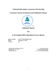
20SYST016 E1 – 2010-01-12
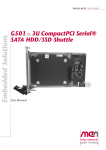
CPCI Rack – Single Euro
with Conduction Cooling
Configuration example
User Manual
®
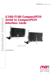
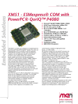
CPCI Rack – Single Euro with Conduction Cooling
CPCI Rack – Single Euro with Conduction Cooling
This enclosure for CompactPCI® cards in 3U format allows to use standard boards
that were designed for ventilated systems even in an environment which needs
conductive cooling. To do this, all critical components are directly coupled to the
housing to divert waste heat to the exterior wall. This reduces the costs involved in
the higher overhead of conduction cooling to the housing, and no PCB space is lost
on the boards for this cooling method.
This extremely robust enclosure is hermetically sealed against impacts from outside,
offers high vibration and shock resistance through the use of wedge locks as well as
special connector types such as MIL-C-38999. The standard front connectors of the
boards are wired to four MIL-C-38999 connectors (three I/O connectors and one
power supply connector) at the rear side of the system inside the housing. Both front
and rear I/O can be made available on these connectors, and the pin-out is always
customized.
The standard CompactPCI boards are fitted into a special "CCA" frame (conduction
cooled assembly) and inserted into the system. The system provides three
CompactPCI® slots for one CPU board with a side card and one I/O board, as well
as a PSU slot with an H15 connector. The distance between the slots on the
backplane is greater than on standard backplanes.
The thermal resistance is 0.4 Kelvin/Watt and the temperature class Tx for 40 W
maximum performance (for boards with an operating temperature of -40 to +85°C).
The enclosure is compliant with IP65 for protection against dust and humidity.
The system is suited for MEN boards F11S, F12N, F13, F14, F15, F17, F18, F19P
and F50C.
MEN Mikro Elektronik GmbH
20SYST016 E1 – 2010-01-12
2
Technical Data
Technical Data
General System Characteristics
• 3 slots for 3U Eurocard boards in CCA frame
• Middle slot (right of the system slot) designed for a side card connected to the
CPU board
• Conduction-cooled
Mechanical Specifications
•
•
•
•
3U card horizontal
Dimensions: 200 mm x 350 mm x 145 mm
Weight: 4500g
IP65 compliant
Connectors
• 4 MIL-C-38999 connectors X1..X4
• X1..X3 for customized I/O
- 59 usable I/O pins
• X4 for power supply
CompactPCI® Backplane
• Compliance with CompactPCI® Spec. 2.0 Rev. 2.1 and IEC 61 076-4-101 (connectors)
• 3-slot
- CPU system slot
- Side-card slot
- Peripheral slot
• System slot on the left
Power Supply
•
•
•
•
•
•
•
•
PSU 3U CCA
Input: 24VDC nominal (18-32V)
Output 5V, 3.3V/35W
Robust internal connection to rear-panel outer connector X4
SMBus
External I/Os for key function
Overtemperature shutdown: 50..90°C (adjustable by SMBus command)
Holdup time according to EN50155 Class S2
MEN Mikro Elektronik GmbH
20SYST016 E1 – 2010-01-12
3
Technical Data
Environmental Specifications
• Temperature range (operation):
- -40°C to +70°C, with up to +85°C for 10 minutes according to class Tx
(EN50155)
- Thermal resistance 0.4 K/W
• Temperature range (storage): -40..+85°C
• Relative humidity (operation): max. 95% non-condensing
• Relative humidity (storage): max. 95% non-condensing
• Shock: according to EN 61373, Class B
• Vibration: according to EN 61373, Class B
Suited for MEN Boards ...
•
•
•
•
•
•
•
•
•
F50C
F11S (in a special CCA version)
F12N (in a special CCA version)
F13 (in a special CCA version)
F14 (in a special CCA version)
F15 (in a special CCA version)
F17 (in a special CCA version)
F18 (in a special CCA version)
F19P (in a special CCA version)
MEN Mikro Elektronik GmbH
20SYST016 E1 – 2010-01-12
4
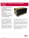
Diagram
Diagram
X1
Operational 1
X4
Power Supply
19
pins
Side-Card Slot
X2
Operational 2
X3
Maintenance
18
pins
22
pins
Rear Panel
MEN Mikro Elektronik GmbH
20SYST016 E1 – 2010-01-12
Peripheral Slot
System Slot
PSU Slot
Backplane
5
Configuration Options
Configuration Options
Slots
• Different number/type of slots (requires change of mechanical dimensions)
I/O
• Individual signal routing to outer connectors
• Individual CCA frame
Connectors
• Different outer connectors (e.g. M12)
PSU
• Input voltage range 9..154V
Mechanical
• Wall-mounting
Please note that some of these options may only be available for large volumes.
Please ask our sales staff for more information.
For available standard configurations see online data sheet.
MEN Mikro Elektronik GmbH
20SYST016 E1 – 2010-01-12
6
Product Safety
Product Safety
!
Electrostatic Discharge (ESD)
Computer boards and components contain electrostatic sensitive devices.
Electrostatic discharge (ESD) can damage components. To protect the board and
other components against damage from static electricity, you should follow some
precautions whenever you work on your computer.
• Power down and unplug your computer system when working on the inside.
• Hold components by the edges and try not to touch the IC chips, leads, or circuitry.
• Use a grounded wrist strap before handling computer components.
• Place components on a grounded antistatic pad or on the bag that came with the
component whenever the components are separated from the system.
• Store the board only in its original ESD-protected packaging. Retain the original
packaging in case you need to return the board to MEN for repair.
MEN Mikro Elektronik GmbH
20SYST016 E1 – 2010-01-12
7
About this Document
About this Document
This user manual describes the hardware functions of the rack, connection of
peripheral devices and integration into a system. It also provides additional
information for special applications and configurations of the rack.
The manual does not include detailed information on individual components (data
sheets etc.). A list of literature is given in the appendix.
History
Issue
Comments
Date
P1
Preliminary issue
2009-12-23
E1
First released issue
2010-01-12
Conventions
!
italics
bold
monospace
hyperlink
This sign marks important notes or warnings concerning proper functionality of the
product described in this document. You should read them in any case.
Folder, file and function names are printed in italics.
Bold type is used for emphasis.
A monospaced font type is used for hexadecimal numbers, listings, C function
descriptions or wherever appropriate. Hexadecimal numbers are preceded by "0x".
Hyperlinks are printed in blue color.
The globe will show you where hyperlinks lead directly to the Internet, so you can
look for the latest information online.
IRQ#
/IRQ
Signal names followed by "#" or preceded by a slash ("/") indicate that this signal is
either active low or that it becomes active at a falling edge.
in/out
Signal directions in signal mnemonics tables generally refer to the corresponding
board or component, "in" meaning "to the board or component", "out" meaning
"coming from it".
Vertical lines on the outer margin signal technical changes to the previous issue of
the document.
MEN Mikro Elektronik GmbH
20SYST016 E1 – 2010-01-12
8
About this Document
Legal Information
MEN Mikro Elektronik reserves the right to make changes without further notice to any products herein. MEN makes no
warranty, representation or guarantee regarding the suitability of its products for any particular purpose, nor does MEN assume
any liability arising out of the application or use of any product or circuit, and specifically disclaims any and all liability,
including without limitation consequential or incidental damages.
"Typical" parameters can and do vary in different applications. All operating parameters, including "Typicals" must be
validated for each customer application by customer's technical experts.
MEN does not convey any license under its patent rights nor the rights of others.
Unless agreed otherwise, MEN products are not designed, intended, or authorized for use as components in systems intended
for surgical implant into the body, or other applications intended to support or sustain life, or for any other application in which
the failure of the MEN product could create a situation where personal injury or death may occur. Should Buyer purchase or
use MEN products for any such unintended or unauthorized application, Buyer shall indemnify and hold MEN and its officers,
employees, subsidiaries, affiliates, and distributors harmless against all claims, costs, damages, and expenses, and reasonable
attorney fees arising out of, directly or indirectly, any claim of personal injury or death associated with such unintended or
unauthorized use, even if such claim alleges that MEN was negligent regarding the design or manufacture of the part.
Unless agreed otherwise, the products of MEN Mikro Elektronik are not suited for use in nuclear reactors or for application in
medical appliances used for therapeutical purposes. Application of MEN products in such plants is only possible after the user
has precisely specified the operation environment and after MEN Mikro Elektronik has consequently adapted and released the
product.
ESM™, ESMini™, MDIS™, MDIS4™, MENMON™, M-Module™, M-Modules™, SA-Adapter™, SA-Adapters™,
UBox™, USM™ and the MBIOS logo are trademarks of MEN Mikro Elektronik GmbH. PC-MIP® is a registered trademark
of MEN Micro, Inc. and SBS Technologies, Inc. MEN Mikro Elektronik®, ESMexpress®, MIPIOS® and the MEN logo are
registered trademarks of MEN Mikro Elektronik GmbH.
All other products or services mentioned in this publication are identified by the trademarks, service marks, or product names
as designated by the companies who market those products. The trademarks and registered trademarks are held by the
companies producing them. Inquiries concerning such trademarks should be made directly to those companies. All other brand
or product names are trademarks or registered trademarks of their respective holders.
Information in this document has been carefully checked and is believed to be accurate as of the date of publication; however,
no responsibility is assumed for inaccuracies. MEN Mikro Elektronik accepts no liability for consequential or incidental
damages arising from the use of its products and reserves the right to make changes on the products herein without notice to
improve reliability, function or design. MEN Mikro Elektronik does not assume any liability arising out of the application or
use of the products described in this document.
Copyright © 2010 MEN Mikro Elektronik GmbH. All rights reserved.
Please recycle
Germany
MEN Mikro Elektronik GmbH
Neuwieder Straße 5-7
90411 Nuremberg
Phone +49-911-99 33 5-0
Fax +49-911-99 33 5-901
E-mail [email protected]
www.men.de
MEN Mikro Elektronik GmbH
20SYST016 E1 – 2010-01-12
France
MEN Mikro Elektronik SA
18, rue René Cassin
ZA de la Châtelaine
74240 Gaillard
Phone +33 (0) 450-955-312
Fax +33 (0) 450-955-211
E-mail [email protected]
www.men-france.fr
USA
MEN Micro, Inc.
24 North Main Street
Ambler, PA 19002
Phone (215) 542-9575
Fax (215) 542-9577
E-mail [email protected]
www.menmicro.com
9
Contents
Contents
1 System Overview . . . . . . . . . . . . . . . . . . . . . . . . . . . . . . . . . . . . . . . . . . . . . . .
1.1 Basic Principle. . . . . . . . . . . . . . . . . . . . . . . . . . . . . . . . . . . . . . . . . . .
1.2 Layout of the Rack . . . . . . . . . . . . . . . . . . . . . . . . . . . . . . . . . . . . . . .
1.3 Signal Routing and Wiring . . . . . . . . . . . . . . . . . . . . . . . . . . . . . . . . .
12
12
12
13
2 Getting Started . . . . . . . . . . . . . . . . . . . . . . . . . . . . . . . . . . . . . . . . . . . . . . . .
2.1 Configuring the Rack. . . . . . . . . . . . . . . . . . . . . . . . . . . . . . . . . . . . . .
2.1.1
Installing Boards in the Rack . . . . . . . . . . . . . . . . . . . . . . . .
2.1.2
Installing Operating System Software . . . . . . . . . . . . . . . . .
2.1.3
Installing Driver Software . . . . . . . . . . . . . . . . . . . . . . . . . . .
2.2 Installing the Rack into an Application Environment . . . . . . . . . . . . .
2.2.1
Dimensions and Mounting Holes . . . . . . . . . . . . . . . . . . . . .
2.2.2
Rack Orientation . . . . . . . . . . . . . . . . . . . . . . . . . . . . . . . . . .
2.2.3
Thermal Considerations . . . . . . . . . . . . . . . . . . . . . . . . . . . .
14
14
15
18
18
19
19
20
21
3 Functional Description . . . . . . . . . . . . . . . . . . . . . . . . . . . . . . . . . . . . . . . . . .
3.1 Power Supply. . . . . . . . . . . . . . . . . . . . . . . . . . . . . . . . . . . . . . . . . . . .
3.1.1
Outer Connector . . . . . . . . . . . . . . . . . . . . . . . . . . . . . . . . . .
3.1.2
Temperature Sensor. . . . . . . . . . . . . . . . . . . . . . . . . . . . . . . .
3.1.3
Digital Input and Standby . . . . . . . . . . . . . . . . . . . . . . . . . . .
3.1.4
Fuse Protection . . . . . . . . . . . . . . . . . . . . . . . . . . . . . . . . . . .
3.2 I/O Outer Connectors . . . . . . . . . . . . . . . . . . . . . . . . . . . . . . . . . . . . .
3.3 Backplane . . . . . . . . . . . . . . . . . . . . . . . . . . . . . . . . . . . . . . . . . . . . . .
3.3.1
CompactPCI Bus. . . . . . . . . . . . . . . . . . . . . . . . . . . . . . . . . .
3.3.2
Side-Card Slot and Peripheral Slot . . . . . . . . . . . . . . . . . . . .
3.3.3
Connection between CompactPCI and Power Supply . . . . .
3.4 Protective Vent. . . . . . . . . . . . . . . . . . . . . . . . . . . . . . . . . . . . . . . . . . .
22
22
22
22
23
23
24
25
25
25
25
26
4 Appendix . . . . . . . . . . . . . . . . . . . . . . . . . . . . . . . . . . . . . . . . . . . . . . . . . . . . . 27
4.1 Literature and Web Resources . . . . . . . . . . . . . . . . . . . . . . . . . . . . . . . 27
4.2 Finding out the Product’s Article Number, Revision and Serial
Number . . . . . . . . . . . . . . . . . . . . . . . . . . . . . . . . . . . . . . . . . . . . . . . . 27
MEN Mikro Elektronik GmbH
20SYST016 E1 – 2010-01-12
10
Figures
Figure 1.
Figure 2.
Figure 3.
Figure 4.
Figure 5.
Figure 6.
Figure 7.
Figure 8.
Figure 9.
Diagram of the CCA rack (excluding power supply unit) . . . . . . . . . .
Signal routing and wiring of interfaces inside the CCA rack. . . . . . . .
Mounting holes at the bottom plate of the CCA rack. . . . . . . . . . . . . .
Dimensions of the bottom plate of the CCA rack . . . . . . . . . . . . . . . .
Mounting orientations of standard CCA rack version . . . . . . . . . . . . .
Outer connectors at rear panel of CCA rack. . . . . . . . . . . . . . . . . . . . .
Backplane connectors . . . . . . . . . . . . . . . . . . . . . . . . . . . . . . . . . . . . . .
Protective vent on the front plate of the CCA rack . . . . . . . . . . . . . . .
Label giving the board’s article number, revision and serial number .
12
13
19
19
20
24
25
26
27
Pin assignment of X4 Power Supply outer connector . . . . . . . . . . . . .
Signal mnemonics of X4 Power Supply outer connector. . . . . . . . . . .
Power supply standby delay timing values. . . . . . . . . . . . . . . . . . . . . .
Pin layout and types of outer connectors X1..X3 . . . . . . . . . . . . . . . . .
22
22
23
24
Tables
Table 1.
Table 2.
Table 3.
Table 4.
MEN Mikro Elektronik GmbH
20SYST016 E1 – 2010-01-12
11
System Overview
1
System Overview
1.1
Basic Principle
The CCA rack is designed to support single-board computers (SBCs) in normal 3U
CompactPCI format. The rack’s backplane connectors adhere to the CompactPCI
standard, but the mounting spacing between these connectors is adjusted to
accommodate the added thickness of so-called CCA frames. These ConductionCooled Assembly frames can make a conduction-cooled board out of almost any
standard, off-the-shelf CPU or I/O board. Each unique board/processor combination
is matched to a customized frame system with a tailor-made heat sink designed to
transfer heat efficiently from the CPU to the frame and housing of the convectioncooled rack enclosure. This has cost and availability benefits, and there is no need to
sacrifice board space for conduction cooling.
Ask our sales team for tailor-made, CCA-frame boards based on standard 3U
CompactPCI.
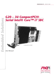
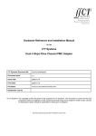
1.2
Layout of the Rack
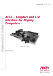
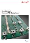
Figure 1. Diagram of the CCA rack (excluding power supply unit)
(Inner top plate)
Top plate
Back plate/
rear panel
Front plate
Backplane
(cPCI)
Outer
connectors
Rear I/O board
Power supply
connector
Protective vent
X1
Operational 1
X4
Power Supply
19
pins
Side-Card Slot
X2
Operational 2
X3
Maintenance
18
pins
22
pins
Rear Panel
MEN Mikro Elektronik GmbH
20SYST016 E1 – 2010-01-12
Peripheral Slot
Bottom plate
with mounting holes
System Slot
PSU Slot
Backplane
12
System Overview
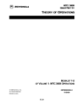
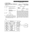
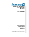
1.3
Signal Routing and Wiring
The following figure – by means of the red arrows – shows how signals are routed
and can be wired inside the CCA rack.
A rear I/O board is located behind the backplane and is connected to the J2
connector of the system slot. It brings the J2 I/O signals to the outer connectors (X1
to X3) at the rear panel. The rear I/O board can also contain interface circuits
necessary to connect the rack to the application environment. It is always
customized to the application’s requirements.
I/O from the 3U boards’ front panels can be wired directly to the rear panel.
Figure 2. Signal routing and wiring of interfaces inside the CCA rack
Rear panel
Rear I/O board
Inner top plate
Backplane
Per.
Rack-internal wiring
from card front
panels to rear panel
Front panel I/O
of 3U cards
CCA-framed peripheral card
X1/X4
Side/
Per.
CCA-framed peripheral card and system CPU
J2
Sys.
X2/X3
PSU
MEN Mikro Elektronik GmbH
20SYST016 E1 – 2010-01-12
CCA-framed PSU card
13
Getting Started
2
Getting Started
This chapter gives some hints for first installation in a system.
2.1
Configuring the Rack
The configuration of the CCA rack needs some advance planning. Being very
compact, the rack provides only three CompactPCI card slots. Because they are
located behind the backplane, the signals of the J2 rear I/O connector of the systemslot card can more or less directly be led to the rear-panel outer connectors, which
support 59 customizable pins on three connectors (X1 to X3).
The two additional peripheral/side cards normally have only front-panel I/O. This
can also be led to the rack’s outer connectors by wiring. The rack’s interior leaves
enough space to safely lead wires between the inner and outer top plate.
Having led all necessary signals to the rear side of the rack, you also need a rear I/O
board in between the CompactPCI backplane and back plate to adapt the signals to
the outer connectors. This is typically done by MEN according to the customer’s
requirements.
Other issues that you should consider in advance are the mechanical and thermal
situation of your application. Because of its cooling fins, the standard rack can only
be installed in horizontal orientation. On the other hand, not all board combinations
may be possible because of the cards’ thermal performance.
For details on...
• rack-internal wiring see Chapter 1.3 Signal Routing and Wiring on page 13.
• I/O outer connectors see Chapter 3.2 I/O Outer Connectors on page 24.
• rack orientation see Chapter 2.2 Installing the Rack into an Application Environment on page 19.
• thermal considerations see Chapter 2.2.3 Thermal Considerations on page 21.
Ask our sales team for tailor-made, custom assembly and configuration options.
When you have your customized rack, boards and software, you can start
implementing your system. The following chapters give you the typical steps that
are necessary. Some or all of these steps may be taken by MEN, depending on the
customer’s requirements.
MEN Mikro Elektronik GmbH
20SYST016 E1 – 2010-01-12
14
Getting Started
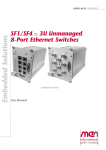
2.1.1
Installing Boards in the Rack
Perform the following steps to install a CompactPCI CCA board:
Open the housing:
; Remove the front plate by unscrewing the 10 screws highlighted in the picture:
; If you need to do some rack-internal wiring with your boards, you should also
remove the top plate by unscrewing the 14 screws highlighted in the picture:
MEN Mikro Elektronik GmbH
20SYST016 E1 – 2010-01-12
15
Getting Started
; There are sealing rubber bands in grooves below the top plate. Take care not to
damage or loose them, and to put them back in place when you re-mount the
top plate.
Grooves for
rubber seal
Insert CCA-compatible CompactPCI boards:
; Insert your CPU board into the system slot of the CCA rack. Take care not to
damage the power supply wires, and make sure to properly align the CompactPCI connectors.
Note: The system slot of the CCA rack is marked by a
plane (slot "1").
triangle on the back-
Note: If you have an MEN CPU, the board may already include a side card
directly connected to the CPU. The slot to the right of the system slot
(slot "2") is specially designed for side cards.
MEN Mikro Elektronik GmbH
20SYST016 E1 – 2010-01-12
16
Getting Started
; Push the board firmly into the rack until the front plate of the board’s CCA
frame evenly aligns with the front plate of the PSU unit. To do this, you need to
fasten the front-panel screws of the board to the guide rails.
; If applicable, insert a peripheral card into the peripheral-card slot (slot "3") of
the CCA rack.
Note: The peripheral slot of the CCA rack is marked by a circle
plane (slot "3").
on the back-
; Use a 2.5-mm hexagon torque wrench to fasten the two wedge locks of every
card that you have inserted into the rack. You need to apply a turning moment
(torque) of 0.8 Nm.
MEN Mikro Elektronik GmbH
20SYST016 E1 – 2010-01-12
17
Getting Started
Connect special board interfaces:
; If you need to wire, e.g., front-panel interfaces of the CCA-framed boards to
the rear panel and outer connectors of the rack, you should do this now. The
rack leaves some space in between the outer and inner top plate to lead wires
between the front and back areas, like the power supply connection:
Space for wiring
between front and rear area
Space for custom rear I/O board
The above picture shows the view inside the rack from the top. For a better
view, this example shows a placeholder for the rear I/O board, which is necessary to make the connection from the CompactPCI backplane to the outer connectors.
; For better access to the outer connectors, you can remove the back plate in the
same way as the front plate. The ten screws are arranged in the same way. (See
page 15.)
When everything is connected, you can power up the system to install and configure
the software. The user manuals of the individual boards usually include useful hints
on first operation.
2.1.2
!
Installing Operating System Software
By standard, no operating system is installed on the boards. Please refer to the
respective manufacturer's documentation on how to install operating system
software!
You can find any software available on MEN’s website.
2.1.3
Installing Driver Software
For a detailed description on how to install driver software please refer to the
respective documentation.
You can find driver software for the PSU (power supply unit) for download on
MEN’s website.
MEN Mikro Elektronik GmbH
20SYST016 E1 – 2010-01-12
18
Getting Started
2.2
Installing the Rack into an Application Environment
2.2.1
Dimensions and Mounting Holes
The rack’s total dimensions are 200 mm x 350 mm x 145 mm. The housing is made
for sturdy screw mounting and provides six mounting holes at its bottom plate.
Figure 3. Mounting holes at the bottom plate of the CCA rack
Figure 4. Dimensions of the bottom plate of the CCA rack
MEN Mikro Elektronik GmbH
20SYST016 E1 – 2010-01-12
19
Getting Started
2.2.2
Rack Orientation
It generally depends on the application environment on how and where the CCA
rack is mounted. Because of the orientation of its cooling fins, the standard rack can
only be mounted on a horizontal surface, as shown in the following figure.
Figure 5. Mounting orientations of standard CCA rack version
Horizontal surface
Horizontal surface
Airflow through cooling fins
Mounting to vertical surfaces
is only possible with a special
rack configuration!
As an option, MEN can also provide the rack for wall mounting, i.e. on a vertical
surface. The cooling fins will then fit the mounting orientation. Please contact
MEN’s sales team for further information.
!
In any case, the surface where the rack is mounted on must provide for sufficient
airflow to the cooling fins. Mounting the rack onto a closed surface, e.g., a table,
will not be sufficient.
MEN Mikro Elektronik GmbH
20SYST016 E1 – 2010-01-12
20
Getting Started
2.2.3
Thermal Considerations
The inner shape of each CCA-framed board inside the rack is unique to the cooling
requirements of this board, accommodating specific hot spots that need thermal
contact with the CCA frame. Those frames are mounted with wedge-lock
connectors for reliable thermal coupling, transferring heat efficiently from the CPU
to the frame and housing of the CCA rack.
The maximum temperature inside the rack is +85 °C. The maximum operating
temperature of the entire rack (i.e. the temperature on the rack’s surface) is +70 °C,
with an allowed +85 °C for maximum 10 minutes. This specification conforms with
the EN 50155 railway standard.
The total thermal resistance (Rth) of the CCA rack is 0.4 °C/W, allowing system
designers to calculate the performance of their applications according to the
following formula:
ΔT = Tinternal - Tambient = Pv * Rth
As an example, this formula would dictate a maximum electrical power of 37.5 W to
be installed in a CCA frame with a maximum allowable temperature of +85 °C and
an ambient temperature of +70 °C:
Pvmax = ΔT / Rth = 15 °C / 0.4 °C/W = 37.5 W
Likewise, given an installed electrical power of 22 W and an outside temperature of
60 °C, the component operating temperature could be calculated as 68.8 °C:
Tinternal = Pv * Rth + Tambient = 22 W * 0.4 °C/W + 60 °C = 68.8 °C
It heavily depends on the thermal performance of your boards on whether you can
implement the desired configuration with MEN’s CCA rack. If you have any
questions or problems regarding thermal behavior, please contact MEN.
MEN Mikro Elektronik GmbH
20SYST016 E1 – 2010-01-12
21
Functional Description
3
Functional Description
3.1
Power Supply
The CCA rack has its own power supply unit (PSU). The PSU supports a voltage
range of 18-32 V and 35 W.
You can find driver software for the PSU (power supply unit) for download on
MEN’s website.
3.1.1
Outer Connector
Table 1. Pin assignment of X4 Power Supply outer connector
E
D
F
G
A
B
C
A
VCC
B
VCC
C
-
D
GND
E
GND
F
-
G
PS_Enable
Table 2. Signal mnemonics of X4 Power Supply outer connector
Signal
Direction
Function
GND
-
Isolated ground
PS_Enable
in
Power Supply enable
VCC
in
+24V nom. supply voltage
Minimum: +18V (-25%)
Maximum: +32V (+33%)
Protected against input voltage reversal
by a fuse.
Connector types:
• D38999/24FB99PN plug
• Mating connector:
D38999/26FB99SN receptacle
MEN offers a set of suitable mating connectors for all four outer connectors of the
CCA rack. Please see MEN’s website for ordering information.
3.1.2
Temperature Sensor
The power supply provides an integrated temperature sensor for the detection of
overtemperature conditions that could cause a destruction of the power supply. The
temperature sensor is configurable within an overtemperature range of +50°C to
+90°C. The temperature limit can be set using the PSU driver software available for
download on MEN’s website.
MEN Mikro Elektronik GmbH
20SYST016 E1 – 2010-01-12
22
Functional Description
3.1.3
Digital Input and Standby
The power supply provides one digital input (PS_Enable) to enable/disable the
output voltages. The digital input is connected to a control line that provides a
controlled shut-down of the CCA rack system.
The power supply generates a maximum standby power of 0.5 W.
The standby condition is defined as follows:
•
•
•
•
Input voltage Uin = +24 V
Digital input = "low" (0 V)
Output voltage +5 V = 0 V (disabled)
Output voltage +3.3 V = 0 V (disabled)
The power supply provides a programmable delay time between the falling edge of
the digital input and the output voltages being switched off. The mode can be set
using the PSU driver software available for download on MEN’s website.
Table 3. Power supply standby delay timing values
Mode
0
No standby delay (default)
1
1 min
2
2 min
3
4 min
4
8 min
5
16 min
3.1.4
!
Fuse Protection
The DC/DC converter of the PSU is protected by a fuse. This fuse is not intended
to be exchanged by the customer. Your warranty for the CCA rack will cease if
you exchange the fuse on your own. Please send your rack and PSU to MEN for
repair if a fuse blows.
•
•
•
•
Current rating: 5 A
Type: fast
Size: 4.5 x 12.1 mm
MEN part number: 5675-0009
MEN Mikro Elektronik GmbH
20SYST016 E1 – 2010-01-12
Standby Delay
23
Functional Description
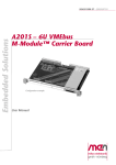
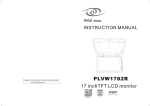
3.2
I/O Outer Connectors
Both the front and rear I/O of the boards inside the CCA rack can be made available
on three MIL-C-38999 connectors located at the back plate. Since the CCA rack is
completely closed during operation, these connectors are the only way of linking up
peripherals.
The connectors all have different types and pin counts, totaling 59 user I/O pins.
Figure 6. Outer connectors at rear panel of CCA rack
X1
Operational 1
X4
Power Supply
19
pins
X2
Operational 2
X3
Maintenance
18
pins
22
pins
Table 4. Pin layout and types of outer connectors X1..X3
A
M
L
N
K U
J
P
V
T
H
R
S
G
L
B
F
K
C
D
E
X1 Operational 1
19 pins
J
H
G
A
M N B
T U P
S R
F
1
21
C
22
D
E
X2 Operational 2
18 pins
X3 Maintenance
22 pins
The exact functional pin-out depends on the cards implemented in the CCA rack. It
is completely customizable. See also Chapter 1.3 Signal Routing and Wiring on
page 13.
Connector types:
X1, 19-pin:
• D38999/24FD19PN
plug
• Mating connector:
D38999/26FD19SN
receptacle
X2, 18-pin:
• D38999/24FD18PA
plug
• Mating connector:
D38999/26FD18SA
receptacle
X3, 22-pin:
• D38999/24FC35PN
plug
• Mating connector:
D38999/26FC35SN
receptacle
MEN offers a set of suitable mating connectors for all four outer connectors of the
CCA rack. Please see MEN’s website for ordering information.
Ask our sales team for tailor-made, custom configuration options.
MEN Mikro Elektronik GmbH
20SYST016 E1 – 2010-01-12
24
Functional Description
3.3
Backplane
The backplane basically includes one CompactPCI system slot and two peripheral
slots. The peripheral slot next to the system slot is designed to support also side
cards for the CPU. The card plugged into this slot must share the front plate with the
CPU. The distance between the two slots complies with a standard CompactPCI
backplane (4-HP slot), whereas the distance between the other slots is greater to
accommodate 3U cards with an individual CCA frame (5-HP slots).
The backplane also provides a slot for a 3U-card power supply unit, using a standard
H15 receptacle connector.
Only the CompactPCI system slot has a J2 connection to route rear I/O signals to the
rear I/O board and – from there – to the outer connectors. The peripheral slots do not
support rear I/O.
Figure 7. Backplane connectors
cPCI Peripheral Slot
“CCA distance“
cPCI Side-Card/Peripheral Slot
“cPCI distance“
J2 RIO
cPCI System Slot
Common
front plate
“CCA distance“
PSU Slot
3.3.1
CompactPCI Bus
The CCA rack supports 32-bit 33-MHz CompactPCI compliant with CompactPCI
specification PICMG 2.0 Rev. 3.0. The backplane provides a CompactPCI reset.
3.3.2
Side-Card Slot and Peripheral Slot
Both the side-card slot (slot "2") and the peripheral slot (slot "3") are ordinary
CompactPCI peripheral slots. However, the distance between the system slot and
side-card slot is smaller than usual. A side-card is a normal CompactPCI formfactor board but is directly coupled to the system slot and shares a front-panel with
the CPU. This means in turn that it is mechanically and electrically possible to plug
any 4-HP peripheral card into slot 2 of the CCA rack, as long as it forms a unit with
the CPU board, with a common front-panel. MEN can provide a suitable CPU-andperipheral-board solution together with the CCA adaption on request. Please contact
MEN’s sales team for further information.
3.3.3
Connection between CompactPCI and Power Supply
The backplane provides an SMB connection between the CompactPCI slots and the
power supply slot. This allows the driver software to access and configure the PSU.
MEN Mikro Elektronik GmbH
20SYST016 E1 – 2010-01-12
25
Functional Description
3.4
Protective Vent
The protective vent at the side of the enclosure provides an effective barrier from
dust and dirt and still allows the sealed housing to breathe with changing
environmental conditions. This prevents pressure from building up and damaging
enclosure seals, exposing sensitive components to water and debris.
Figure 8. Protective vent on the front plate of the CCA rack
MEN Mikro Elektronik GmbH
20SYST016 E1 – 2010-01-12
26
Appendix
4
Appendix
4.1
Literature and Web Resources
• CCA rack data sheet with up-to-date information and documentation:
www.men.de/products/0701-0054.html
4.2
Finding out the Product’s Article Number, Revision and
Serial Number
MEN user documentation may describe several different models and/or design
revisions of the CCA rack. You can find information on the article number, the
design revision and the serial number on a label attached to the chassis.
• Article number: Gives the product’s family and model. This is also MEN’s
ordering number. To be complete it must have 9 characters.
• Revision number: Gives the design revision of the product.
• Serial number: Unique identification assigned during production.
If you need support, you should communicate these numbers to MEN.
Figure 9. Label giving the board’s article number, revision and serial number
Made in
Germany
MEN Mikro Elektronik GmbH
20SYST016 E1 – 2010-01-12
Article No.: 0701-0054
Serial No.: 000001
Rev. No.: 00.00.00
27