1
Section 5-2
Handling Problems
Handling Problems
Handling Problems
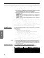
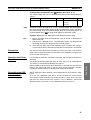
Preliminary Checks
Check item
Items to check
Is the power supply
turned ON?
If the power supply is turned ON, the READY indicator will be
lit.
Was wiring performed correctly?
Check all of the wiring.
Were settings performed correctly?
• Check the switches to see if they are set correctly.
• Read out the settings to see if they have been set correctly.
• Read out all settings to see if any of them are incorrect.
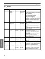
Handling Problems
Condition
Communications
cannot be performed.
Correction
• If the SD/RD indicator does not light when communications
are attempted, there is a problem with the communications
line. Check the wiring of the communications line.
• If a communications converter is being used, check the settings of the converter to see if they are correct.
• Check the settings of SW1 and SW2 to see if they agree with
the settings of the host.
• Check the data length, number of stop bits, and parity to see
if they are the same as the host. If any of the settings are
incorrect or if any are unknown, use the following method for
communications.
1. Set SW2 to 7. (If more than 16 communications unit numbers are used, set SW2 to F.)
2. Set the baud rate, data length, number of stop bits, and parity of the host to the default values for the G3ZA.
If a converter is being used, set the converter to the same
values.
3. This should enable communications. Change all settings to
the correct values.
• Check the communications line to see if it is correct.
Outputs do not turn
ON.
• Unless the OCC indicator is lit and the control variable is set
to 0.0%, then there is a problem in the wiring. Check the wiring of the control outputs.
• If the ERROR indicator is lit or flashing, refer to the corrections given in the Error Table on page 58.
Returning settings to • Initialize the settings with an Operation Command. All of the
default values
settings can be returned to their default values. Refer to the
Status Lists on page 65 in the Appendix for default values.
Current cannot be
detected correctly.
• Check to see if the CT setting in the G3ZA matches the CT
that is connected. Refer to 4-3 Selecting the CT (4-channel
Models Only) V2 .
An output is not stable.
• Check to see if the SSR setting in the G3ZA matches the
SSR that is connected. Refer to 4-2 Selecting the SSR (Control Method) 4 or 8-channel Models) V2 .
59
Troubleshooting
5-2