1
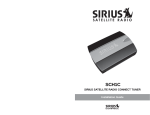
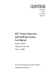
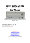
Supervisory Control and Data Acquisition (SCADA) System
For The Centralized Traffic Control (CTC) Equipment
John W.M. Cheng Rick Porath
Micheal Kadour
Canadian National Railway
University of Waterloo
14th Fl., 935 de La Gauchetiere West
Montreal, Quebec
Canada H3B 2M9
e-mail : [email protected]
[email protected]
Waterloo, Ontario
Canada
email: [email protected]
ABSTRACT
Modern railway networks are equipped with Centralized Traffic Control (CTC) systems to
facilitate train traffic control. Due to the variety and large number of such CTC field equipment, railway
companies rely on various labor-intensive and highly repetitive maintenance programs to ensure safe and
reliable services. To improve the productivity of such maintenance activities, as well as to provide the
highest level of service reliability, a Supervisory Control and Data Acquisition (SCADA) system for the
CTC field equipment is envisioned to be an essential tool for the maintenance work force.
This paper presents the vision, concept and the prototype development of a SCADA system
designed to monitor different CTC field equipment for the Signals and Communications (S&C)
maintenance work force. Using the prototype CTC SCADA system, performance information of the power
switches, track circuits, battery conditions and relay contact positions can be monitored locally or remotely.
The experiences of implementation and monitoring results are presented and discussed.
Key Words : CTC, SCADA, Motor Current Signature Analysis (MCSA), Equipment Health Monitoring.
INTRODUCTION
Today, major railway networks are equipped with Centralized Traffic Control (CTC) systems to
provide the facilities and means to monitor and control train traffic in a safe and coordinated manner.
Typical CTC systems include numerous field equipment, e.g. power switches and track circuits, of which
require many labor-intensive procedures and repetitive inspection programs to maintain. In the event of any
force outages caused by equipment failures, fatigue or adverse weather conditions, there could be
significant downtimes and repair costs incurred due to traveling, troubleshooting, repair, replacement and
overtime charges.
To improve the productivity of maintaining the CTC field equipment, as well as to provide the
highest level of performance reliability, a Supervisory Control and Data Acquisition (SCADA) system
designed for the CTC field equipment is envisioned to be an essential tool for the railroad maintenance
work force. Such a tool not only can provide continuous monitoring of the equipment but also can lead to
the development of an optimal maintenance program which will eventually improve productivity as well as
service reliability.
An investigation of how to apply the latest SCADA technology to monitor the health of critical
CTC field equipment was initiated at Canadian National Railway (CNR) in 1998 and this paper describes
the vision, design philosophy and the implementation experiences of a CTC SCADA prototype system.
CTC SCADA, A VISION
The CTC SCADA system proposed in this paper is designed for and will be used by the Signals
and Communications (S&C) front-line maintenance work force on a regular basis. The main goal of the
CTC SCADA is to facilitate the health monitoring of critical CTC field equipment in a cost-effective and
proactive manner such that the reliability of services will be improved. To this purpose, a CTC SCADA
system is envisioned to have the following objectives :
1.
Improving Equipment Reliability Through Equipment Health Monitoring : The health condition of
critical CTC equipment shall be monitored continuously by the SCADA system such that any apparent
degradation of performance or defect can be detected prior to actual failures. Automatic health check
programs within the SCADA system shall analyze the collected data to generate appropriate alarms
and/or warning messages to alert the maintenance personnel. As such, proactive actions or preventive
maintenance can be carried out to avoid major damage to equipment or to mitigate any damage. Some
of the potential areas of application include:
•
Power-operated Switches : It has been shown in [1] that Motor Current Signature
Analysis (MCSA) techniques can be used to monitor and diagnose the health of
power switches. The CTC SCADA shall apply the same methodology to collect,
store and analyze the current signatures such that automatic diagnoses of poweroperated switches can be provided to the maintenance crew on a daily basis;
•
Power Supply : The CTC SCADA shall be able to monitor the AC and DC power
supplies in CTC bungalows such that the service continuity, power quality, backup
battery reserves and readiness can be measured and recorded for operation as well as
for planning purposes;
•
Track Circuits: DC and coded track circuits shall also be monitored such that the
effects of climatic changes on track ballast resistivity can be monitored. As such,
methodology or devices can be designed to adjust the track circuits automatically to
compensate for ballast resistivity swings.
2.
Reducing Maintenance Costs and Optimizing Maintenance Schedule :Presently, the CTC plants
require a labour-intensive maintenance program to ensure safety and service reliability. By introducing
a CTC SCADA system, certain critical equipment shall be monitored and evaluated automatically on a
continuous manner. Subsequently, existing maintenance procedures can be simplified and
their
associated maintenance schedules can be optimized without jeopardizing safety and performance
reliability. For instance, the maintenance schedule can be organized on a utilization rate basis instead of
the conventional periodic basis.
3.
Capturing Intermittent Problems : Intermittent problems such as temporary loss of shunt, unexpected
loss of a clear signal, are common in CTC field equipment. These problems are usually hard to reproduce. However, with a CTC SCADA system, its data acquisition and recording capability can be
used to monitor problematic site(s) such that any abnormality and unfavorable conditions will be
captured as they happen. An analogy of this is the SCADA system shall resemble the ‘black box’ data
recording device commonly used in the airline industry. Subsequently, troubleshooting and analysis
time will be reduced and problem identification may be expedited.
4.
Environment Monitoring and Controls : Indoor and outdoor temperature readings collected by the
CTC SCADA system shall provide the necessary information to assess or even to
adjust the
environmental controls of the bungalows, namely air-conditioners and/or heaters. Weather related
information collected can also be used to control the snow clearing devices used alone side with some
power switches. As a result, the CTC SCADA system not only can conserve energy but also extend the
longevity of the equipment.
5.
Improving Response Time and Associated Cost for Remote CTC Plants: Some CTC sites are remote
with little or no road accessibility. In these cases, the most time-consuming part is the travel. A CTC
SCADA system shall provide real-time as well as historical data to the maintainer/technician via a
phone or the company network such that historic information, diagnostics and corrective actions (e.g.
resetting the component) may be initiated promptly. Subsequently, it will reduce the downtimes and
any associated costs.
6.
Centralized Reporting Capability : The accumulated data from the CTC SCADA system shall be
collected at a centralized location which can then be easily assembled, sorted and eventually used for
different planning, equipment availability statistics, strategic planning and archiving purposes by
different groups within the company.
The above mentioned objectives are not necessary complete but will serve as the framework of
what the CTC SCADA system shall encompass. Based on these objectives, a prototype was developed at
CNR and the following sections describe the experience of the development.
DESIGN CONSTRAINTS AND CRITERIA
There are three main constraints associated with the nature of this SCADA system. First, since
there are numerous state variables that may be of interest in a CTC bungalow, the sampling mode and
frequency could have a wide range. For instance, some state variables such as temperature and battery
voltage, are in general a steady-state variable. In other words, they don’t vary too much in a short time, e.g.
within seconds. However, the power switch current signatures [1] are in general a transient variable
because they happen randomly and only lasts a few seconds. As a result, a versatile data acquisition system
will be required to accommodate different forms of signals. Secondly, due to the large number of CTC
bungalows or cut cases that have to be monitored, the cost of the selected data acquisition equipment must
be economical and cost-effective. Thirdly, the means of communication also posts a challenge because not
only its cost is an important issue but also the availability and coverage of the communication networks may
also post a formidable challenge to many sites.
In view of these constraints, the following design criteria were adopted to develop the prototype
system :
•
To provide maximum versatility of the CTC SCADA system, the selected equipment
shall be a general purpose data acquisition system of which it can support multiple
data triggering modes as well as different sampling frequencies. Furthermore, its
capabilities shall also include local storage such that any transient and steady-state
recordings can be retained locally and retrieved at will.
•
To reduce equipment and development costs, all hardware and software used shall be
readily available commercially. As such, development costs shall be minimized;
•
As a starting point, the commercial phone system, i.e. wired and cell, shall be the
means of communications for the prototype development to optimize cost and
coverage issues.
PROTOTYPE DESIGN AND IMPLEMENTATION
The basic design was comprised of three major parts, namely Data Acquisition, Communications,
and Office Controls. Figure 1 shows a typical installation of the CTC SCADA system in a cut case.
Figure 1 CTC SCADA prototype in a cut case
Data Acquisition
Since the desired signals to be monitored might be currents, temperatures, or high voltages, signal
transducers and conditioning devices are required. In this development, a set of voltage isolation amplifiers
were designed and built so that a large range of voltages (e.g. 2-300 V) can be measured. Furthermore, Hall
effect current transducers (up to 50 A) were also used to provide a non-intrusive type of monitoring
capability. In fact, the non-intrusive current sensors were extensively used throughout the development
because they provide a much safer means of monitoring set up and a much easier way to install.
Since the applications of the system are varied, flexibility is crucial for the data logger. A
commercial data logger [2] with multiple input channels was selected for this application. This data logger
is not only compact and designed for a wide operating temperature (-55° C to 80°C) but also is highly
programmable. Programming can even be performed remotely using an external modem. The logger is
capable of recording based on a pre-defined triggering condition, a periodic sequence, or a user request. As
events occur, the logger stores the data locally. Currently 62,000 data records are allow which can
accommodate several days of recording for a site with up to 10 power switches. These recordings are then
transmitted to the office either on a periodic or upon-request basis.
Along with the versatile programming capability, the data logger provide an ample external
interface capabilities for different signals. As such, varied input configurations are possible. For example,
the same logger can be configured to monitor up to 12 power switches using single-ended mode or 6
isolated voltage measurements using differential mode. The sampling rate of individual channels is also
configurable. For this application, sample rates ranging from 100 Hz (burst mode recording) to hourly
readings have been used. With these transducers, signals conditioners and the data logger, a variety of
signals can be captured and converted into digital form ready for transmission.
Communications
For the high density track areas, e.g. yard entrance, the regular dial-up phone system is used. This
allows for the least expensive and simplest way of communications. However, since a lot of the CTC
bungalows are not necessarily equipped with phone service, cellular phones are also used. With the rapidly
expanding cellular networks, this mode of communication becomes the most affordable and attractive
solution for the communication part. Furthermore, due to the local storage capability of the data logger, the
periodicity of the communications between the sites and the office can be programmed to suit the types of
applications as well as to minimize air-time charges. For instance, the office system communicates with the
sites on an hourly basis and collects all stored data on a daily basis. The average air-time per call is less
than a minute.
Office Controls
The office controls is a PC-based system running a commercially available SCADA software[3].
This software provides all the basic functionalities of a SCADA systems, namely communications, data
processing, alarms, historic recording, analysis packages and graphical displays and controls.
After installing the data logger at the site, the corresponding site configuration is entered into the
CTC SCADA data base. Typical site information includes site name, signal names, polling periodicity,
transient capture duration and local phone number. A custom-made server program was developed for this
CTC SCADA application. This server program acts as a background process which is responsible to
communicate with all the sites automatically and also to process any manual request from the user. For
example, the server itself is a queuing system that controls the use of the communication port which is
connected to a modem. Whenever automatic timed polling occurs or a user manually initiates a poll, the
request is queued. The server monitors the queue and makes the corresponding connections to the remote
sites. The designed system is capable of three types of remote processes: snapshots, downloads and site
configuration. Snapshot is for uploading the instantaneous steady-state signals; downloads are for the
stored transient recordings and site configuration is for re-configuring the remote site. With a queued
architecture, the user can issue any number of manual requests at anytime with no concern of
communication traffic. Communication failures are logged also to indicate any potential problems. The
database is ODBC compliant and thus fully accessible though many other major software packages such as
MS Access or MS Excel.
Human Interface
Using the graphical user interface tools provided by the SCADA software, the following user
interface screens are created to assist the users to view the status and conditions of the field equipment.
They are:
Figure 2 CTC SCADA interface of a cut case
•
Individual Site Overviews : The site overview window is designed to present the user with the
current status of the individual bungalow. Figure 2 is the Site Overview of the cut case shown
in Figure 1. It includes displays of remote site data, an alarm window, a status bar, and a menu
to navigate the system. All steady-state signals are shown in the display windows along with
the internal temperature, last update time, and status lights for alarms and communication. In
addition, a historical recording of individual data base points can also be plotted on this
window for examination;
•
Historical Data Trending : As data is collected periodically from the remote site it is stored in
a real-time database. The historical trend viewer interacts with this database to construct fully
scalable, interpolated charts of any field data;
•
Alarm Notification and Acknowledgment :If any data point enters an alarm state (i.e., a falling
battery voltage) several indicators are available to notify the user. First if the site is currently
being viewed, a display light will flash bright red. Second, the alarm window will contain an
entry for the data point. Lastly an audible sound will emit every 15 seconds. These indicators
will persist until the user manually acknowledges the alarm. User acknowledgment will
silence the audible alarm; however, the other indicators stop only after the data point returns to
normal operating conditions. The alarm acknowledgment window can also be seen on the left
corner of Figure 2 ;
•
Analysis Tools : Once data is gathered to the office any number of things can happen.
Depending on what is being monitored a variety of signal specific analysis tools can be
created. These might be health condition checks, both manually or automatically, or statistical
analyses.
The real benefits of the CTC SCADA system will probably be realized in this
analysis stage. At the present time, the concentration is to develop automatic tools to diagnose
power switch and coded track problems. The following section will describe in more details
on the analysis part.
RESULTS AND EXPERIENCES
The CTC SCADA project was initiated in late 1998 and the first prototype was designed,
assembled and deployed by the summer of 1999. Five units of the prototypes were eventually built by the
year end of 1999 and four of them are currently installed with the fifth unit acting as a development unit.
The configuration of the four sites are summarized in Table 1.
Table1 : Summary of CTC SCADA PROTOTYPE DEPLOYMENT
SITE 1
SITE 2
SITE 3
SITE 4
Subdivision
Montreal
Montreal
Kingston
St. Hyacinthe
Mileage
6.16
6.23
10.33
55.33
Housing
Bungalow
Cut Case
Bungalow
Bungalow
Power Switch
9
9
4
-
DC Power Supply
1
1
1
-
Track Circuit
-
-
2
-
Battery Condition
-
-
2
-
Relay Status
-
-
-
12
Total Number of Channels
12
12
10
12
Power Switch Defects
Figure 3 shows a series of current signatures captured by the CTC SCADA system on one of the
power switches being monitored. It is apparent that the current signatures on this particular switch have
changed drastically between 21/5 and 22/5. Not only the duration of the throws was extended but also the
amplitudes of the current had increased significantly and also fluctuated violently. The maintenance
personnel was immediately called to check out the switch and it was found that there was major water
infiltration in the power switch compartment. It is abnormal that this kind of water infiltration to happen
because the power switches are normally sealed and routinely checked. The problem was caused by the
deterioration of the seal and a major rainfall in the area. In this example, no abnormality was reported by
the Rail Traffic Controller. The unhealthy condition of the power switch would not likely be identified until
the next routine maintenance check is performed. As such, this is a good illustration of the value of what a
CTC SCADA system can offer.
Figure 3 Current signatures of a power switch with water infiltration
Similar to the above example, there were also other defects spotted through the CTC SCADA
system on other power switches being monitored, namely :
n
Defective commutator brush;
n
Position rod out of adjustment; and
n
Unstable stock rail.
Operation Duty Cycle
In addition to the current signatures, the CTC SCADA also provides statistical data of the
frequency of the power switch throws. For instance, Figure 4 shows the switch viewer of the CTC SCADA
of which the 7-days statistical records of a particular switch are shown along with current signature.
Through these data, it was revealed that the utilization of the power switches could vary significantly. Some
switch could have 20-25 throws per day while an adjacent switch only has 1-3 throws per week. Such
information could lead to the development of
new maintenance and inspection programs based on
equipment utilization. Contrary to the periodic maintenance program, e.g. monthly inspection, presently
used, such new programs could be more cost-effective and flexible. An analogy of this is to have a car
checked every 8,000 km or 3-months of driving, which ever comes first.
Figure 4 CTC SCADA power switch current signature viewer
Battery Charging/Discharging Monitoring
Figure Z shows a historical plot of the charging and discharging current of the B12 battery bank in
a bungalow over a period of 10 days. Even though the samples are taken on an hourly basis, it is clear from
this graphical display that the charging current has a spurious nature which corresponds to the nature of how
the charger works. On the contrary, the discharge current displays a much more constant load pattern which
is also expected. From these data, it can be seen that the charging and discharging patterns can easily be
used as a means to monitor the health of the battery bank, the charger, the total load and even any ground
fault conditions (For example, the energy pumping into the battery should be fairly constant and comparable
with the energy taken out by the load).
Figure 5 CTC SCADA interface for battery bank discharge and charging conditions
Swing Bridge Monitoring
Figure 6 shows a group of indications which in fact represents numerous statuses of a swing bridge
near Montreal. As part of the evaluation of a new proximity sensor based detection system used to replace
the SCC boxes on the bridge, statuses of the proximity sensors and the existing SCC boxes are collected by
a CTC SCADA unit and telemetered to Montreal for monitoring purposes. As such, the performance of the
new and existing systems, especially when there is a train on the bridge, can be studied.
Figure 6 CTC SCADA interface for bridge monitoring
CONCLUSIONS
The initiative and vision of a CTC SCADA system designed to improve CTC field equipment
reliability are presented in this paper. A prototype system using only off-the-shelf products was also
designed, implemented and deployed for different monitoring purposes. The experiences of building the
prototype and its monitoring results are also described. It is demonstrated through the power switch
example that the health conditions of these field
equipment can be effectively monitored such that
proactive measures can be carried out to avoid major repair costs or service interruption. More importantly,
the success of the prototype development provide many insights and experiences of applying the SCADA
and health monitoring technologies in the railroad industry to enhance performance and reduce costs.
ACKNOWLEDGEMENT
The authors would like to thank Messrs.Yves Langis, Martin Fortier and Michel Geneau of the
S&C Maintenance Force in the Montreal area and Mr. Les Kulasza of ERC in Winnepeg for their
enthusiasm and dedicated services which made the deployment of the prototype units and the experiments
on the power switches highly successful.
REFERENCES
[1]
J.W.M. Cheng, “Power Switch Health Monitoring using Motor Current Signatures”, AREMA
Conference Proceedings, Baltimore, September 1999.
[2]
Campbell Scientific CR10X Measurement and Control Module Operator’s Manual, Rev. 5/97.
[3]
National Instrument BridgeVIEW User Manual, 1998.