1
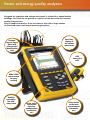
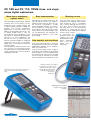
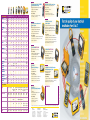
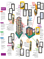
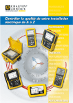
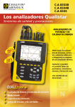
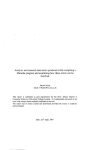
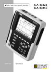
C.A 8230
In the field or in the lab:
real-time monitoring of electrical installations
SINGLE-PHASE
POWER AND
QUALITY
ANALYSER
■ Intuitive to use
■ Large graphic screen, easy to read
■ Measures very weak and very strong currents
■ Analysis of energy quality
■ Analysis of phase shift
■ Energy balance
■ "Data logging" function
■ Display of the waveform of a motor starting current
■ Parallel access to all measurement modes
■ Excellent value for money
C.A 8230: SINGLE-PHASE POWER AND QUALITY ANALYSER
The C.A 8230 single-phase power
analyser is intended for tradesmen and
installers working in collective buildings,
for the private and public sectors, and for
maintenance departments. Economical
and very simple to use, it is especially
well suited to the monitoring of electrical
installations, in particular those including
systems using power electronics.
Special care has been taken to make
mastering the C.A 8230 easy; access to
the various functions is direct. For even
more simplicity, and safety, it recognizes
the
type
of
sensor
connected
automatically.
It is perfectly at home in the field, but its
retractable stand allows desktop use as
well. Dataviewer software multiplies its
capabilities tenfold (configuration and
transfer of data to a PC for processing).
The number of quantities investigated
(VA, VAR, W, PF, etc.) also makes this
instrument very attractive for technical
and technological training use. And the
large graphic screen (320 x 240 pixels) is
perfect for demonstrations.
CHARACTERISTICS
V Max
600 V RMS
I Max
(according to sensors)
5 mA to 6 A / 300 mA to 120 A = MN 93A
2 A to 240 A = MN 93 - 3 A to 1200 A = C 193
10 A to 1400 A = PAC 93 - 10 A to 6500 A = Ampflex 193
Power
1.2 VA to 3,9 MVA - W, VAR, PF / Cos / Tan
Precision
0.5%
Harmonics
THD V, A, VA, 50 orders, RMS and %. Expert mode on V and A
Values
Min, Max, Peak, KF, PST, FC
Functions
Surveillance of thresholds
Phase rotation
Viewing of motor starting
Memory
1.5 Mo
Pass band
40 -70 Hz
Sampling frequency
12.8 kHz
Power supply
Mains. Rechargeable NiMH batteries
(40 h between charges with backlighting off - or 8 h).
TO ORDER
P01.1606.31
- 1 C.A 8230 (211 x 208 x 60 mm) instrument with: 1 carrying bag, 6 installed 1.2 V batteries, 1 red banana cord (straight-straight),
1 black banana cord (straight-straight), 2 4 mm probe tips (1 red and 1 black), 2 alligator clips (1 red and 1 black), 1 MN93A clamp,
1 line power adapter, 1 RS 232 optical cord, and Data Viewer processing software
YOUR DISTRIBUTOR
OTHER ACCESSORIES
•
•
•
•
•
•
CLAMP MN93A BK . . . . . . . . . . . . . . . . . . . . . . . . . . . . . . . . . . . . . . . . . . .
CLAMP MN93 BK . . . . . . . . . . . . . . . . . . . . . . . . . . . . . . . . . . . . . . . . . . . .
AMPFLEX A193 450 mm BK . . . . . . . . . . . . . . . . . . . . . . . . . . . . . . . . . . .
AMPFLEX A193 800 mm BK . . . . . . . . . . . . . . . . . . . . . . . . . . . . . . . . . . .
CLAMP PAC93 BK . . . . . . . . . . . . . . . . . . . . . . . . . . . . . . . . . . . . . . . . . . .
CLAMP C193 BK . . . . . . . . . . . . . . . . . . . . . . . . . . . . . . . . . . . . . . . . . . . . .
FRANCE
Chauvin Arnoux
190, rue Championnet
75876 PARIS Cedex 18
Tel: +33 1 44 85 44 85
Fax: +33 1 46 27 73 89
[email protected]
www.chauvin-arnoux.fr
UNITED KINGDOM
Chauvin Arnoux Ltd
Waldeck House - Waldeck Road
MAIDENHEAD SL6 8BR
Tel: +44 1628 788 888
Fax: +44 1628 628 099
[email protected]
www.chauvin-arnoux.co.uk
P01.1204.34
P01.1204.25
P01.1205.26
P01.1205.31
P01.1200.79
P01.1203.23
MIDDLE EAST
Chauvin Arnoux Middle East
P.O. BOX 60-154
1241 2020 JAL EL DIB (Beirut)
Tel: +961 1 890 425
Fax: +961 1 890 424
[email protected]
www.chauvin-arnoux.com
906 211 124 • Ed. 01 - 10/05 • Characteristics subject to modifications according to technological developments.
C.A 8230
C.A 8352
Keeping up with the standards
Complete electrical network analysis
at the tips of your fingers!
■ All measurements for complete analysis: powers, harmonics,
flicker, symmetry, remote control signals, etc.
■ Self-explanatory use
■ Touch screen user interface
■ Data processing and report publishing software
■ Monitoring as per EN 50160 standard
■ Network connection
Power
Quality
Monitor
Presentation
✔ Internal memory data storage:
6 months recording capacity
✔ Navigable, easy-to-use file structure
✔ Monitoring and network connection capacity
✔ Protocol write-ups and test report publishing
✔ Simultaneous function display
✔ Instrument use simplified with
touch screen and WindowsTM
operating system
Parameters
Analysis parameters according
to EN 50160 standard in effect
• Network frequency
• Supply voltage
• Fast and slow voltage variations
• Short and long interruptions in supply
• Voltage dips and asymmetries
• Harmonic and interharmonic voltages
• Temporary voltage swells at 50 Hz
Flicker analysis
• Flicker analysis as per EN 61000-3
and EN 61000-4-15: short-term (Pst)
and long-term (Plt) flicker
Voltage and current analysis
• TRMS and average values
• Peak value and crest factor
Power analysis
• Generated and consumed active power
• Inductive and capacitive reactive power
• Apparent power, power factor, cos ϕ
• Calculation of energies on each phase
Harmonics break-down up to 50th
order
• Harmonics: current, voltage, active
and reactive power in relation to the
fundamental and in absolute
• Phase shift for each harmonic
• THD: overall and order by order
• Direction recognition for each harmonic order
• Interharmonics spectral analysis
Unbalance and system symmetry
analysis
• System symmetry measurement:
positive, negative and zero sequence
components
• Phase shifting
• Absolute value of voltage and current
for the complete spectrum
• Fresnel diagram representation in 3U
and 3I
• Overall unbalance of three-phase
network
HV network analysis (high voltage)
• Records “short-circuit” events (faultograph function)
• Remote control signal analysis: definition
and verification of the frame
Specifications
INPUT SPECIFICATIONS
Voltage inputs:
Current inputs:
Analogue inputs:
Binary input:
With transient option:
4 channels up to 2 kVpp
4 channels,
range depends on sensors used:
MN 95: 0.2 to 6 A
C145 clamp: 2 to 1200 A
AmpFLEX A195: 25 to 3000 A
Accuracy: < 1%
Up to 16 channels, max.1 Hz (optional)
For recording environmental conditions,
depending on the application
1 external 24 VDC channel for recording start-up
1 binary output, dry contact, 100 V max
(for “transient triggering” status)
1 external 24 VDC binary input (for “transient
triggering” mode start-up)
Making reports
MAIN SYSTEM
Main processor:
Working memory:
Display:
User interface:
Equipment interface:
Sampling rate:
A4 report print out of analyzed
data for selected time windows
256 Mbyte RAM for recording start-up
10 Gbytes
10" LCD color screen
touch screen
1 USB port for keyboard, 2 x RS232 ports:
data logger (optional), printer, binary I/O
9.6 kHz/channel maximum (38.4 kHz in transient mode, be it 25 µs)
GENERAL SPECIFICATIONS
Analysis standards met:
Electrical safety:
EN 50160
EN 61000-2, -3, -4
EN 61000-4-15
EN 61000-4-30
IEC 61010-1, 500 V, category III
pollution degree 2
ENVIRONMENTAL CONDITIONS
Operating temperature:
Storage temperature:
Relative humidity:
Dimensions:
Weight:
Supply voltage:
-10°C to +50°C
-20°C to +70°C
10% to 90% (with no condensation)
360 x 300 x 150 mm
4 kg
85 to 135 VAC and 180 to 265 VAC
COMMUNICATION
Via modem as per publication: CCITT V90 56 kbds
Via Ethernet
Functions
Input configuration
and connection
Oscilloscope mode
➤ Single and three-phase network (3 or 4-wire)
➤ Current sensor configuration (AmpFLEXTM,
C and MN clamps)
➤ Direct input possible up to 5 A
General set-up
➤ Graphic representation of
harmonics and interharmonics: current, voltage
and power
➤ Harmonic current
direction recognition
(IN or OUT)
➤ User I.D. information
➤ Saving the set-up
used for each set
of measurements
➤ Configuring the
"data recording"
mode
Vector scope
Harmonics
analysis
➤ Voltages, currents and
harmonics
➤ Phase connection and
rotation verification
➤ Rundown of different
measurements on each phase
➤ 4 voltages and 4 currents
➤ Graphic waveform representation
Recording transients
Monitoring voltage
Flicker meter
➤ Voltage fluctuation
representation with
value/standard
report
➤ Monitoring as per
EN 50160 standard
➤ Changing threshold
values
➤ DISDIP representations
Monitoring power and energy
➤ Tabulated voltage, current,
power, and energy
➤ Min, max, and average
value monitoring
➤ Power profile display
➤ Graphic representation
over time
➤ Short-term flicker
➤ Long-term flicker
➤ Data logger module
➤ 8 configurable analogue
inputs: 4-20 mA current
or 0-10 V voltage
➤ 8 configurable thermocouple
inputs: J, K, T…
➤ Frequency: 1 Hz
RMS hp mode
➤ Recording of Min, Max
values in U and I calculated
on a 1/2 period (10 ms)
during an integration period
➤ ITIC, CBEMA table
Data logger
Checking remote
control signals
➤ Monitoring
➤ Waveform recording for 10 seconds
➤ Event summary table
➤ Event time-stamping and duration
➤ 1 binary input for triggering the recording externally
Symmetry analysis
➤ Remote control signal tracking
and recording
➤ Measurement on the 3 phases
➤ Graphic display of the frame:
starting date
➤ Max and Average U and I of received
signal
Remote communication
➤ Measurement on three-phase
network
➤ Zero, positive, and negative
sequence and RMS current
and voltage
➤ Unbalance factor in U and I
For data display and recovery:
➤ Using an external modem
➤ Communication via Ethernet network
PC software
➤ Data processing
➤ Report publishing
➤ Printing out graphs and tables
➤ Exporting data to
spreadsheets (ExcelTM, …)
TO ORDER
To order the instrument configured to your needs, fill out the boxes in the order form below
code CA 8 3 5 2
Power Quality Monitor
Standard instrument includes harmonic analysis, oscilloscope mode, vector scope:
standard model supplied with carrying bag, 4 current leads (5 A max.),
8 voltage leads, 8 crocodile clips, data processing software CD ROM,
USB cable, plus all options marked in the order form.
0 or 1
0 or 1
0 or 1
0 or 1
0 or 1
0 or 1
0 or 1
Current sensors
• None
• Set of 4 x C145 clamps (1000 A - Ø 52 mm)
• Set of 4 x AmpFLEX A195 (3000 A - Ø 140 mm / length 450 mm)
• Set of 4 x AmpFLEX A195 (3000 A - Ø 250 mm / length 800 mm)
• Set of 4 x MN95 clamps (5 A - Ø 20 mm)
X
C
A
A
M
User manual languages
• French (by default)
• English
• German
• Italian
• Spanish
X
X
1
2
N
F
G
A
I
E
2P+E mains supply lead
• French, German or Spanish (by default)
• English
• Italian
• Swiss
R
B
L
T
S
F
G
I
C
ACCESSORIES
• 4 current leads (maxi 5 A) ................................................................................................P01.2951.84A
• 4 x C145 clamps (1200 A) ...............................................................................................P01.1203.19A
• 8 voltage leads (4 blue, 4 black) ....................................................................................P01.2951.83
• 4 x AmpFLEX A195 800 mm (3000 A) .........................................................................P01.1205.20
• 4 x AmpFLEX A195 450 mm (3000 A) .........................................................................P01.1205.19
• 4 x MN95 clamps (5 A)........................................................................................................P01.1204.29
• 1 USB connecting cable.....................................................................................................P01.2951.85
• Carrying bag ...........................................................................................................................P01.2980.34
COMPLEMENTARY ORDERS
Optional functions to add to those already on your instrument can be ordered.
Be sure to include the instrument's serial number in the order form.
O P T Serial number
Power analyzer, RMS hp
Flicker meter, EN 50160 analyzer
Transient recorder
Data logger
Remote control signals
Power 2: symmetry, impedance
Remote drive via modem
FRANCE
Chauvin Arnoux
190, rue Championnet
75876 PARIS Cedex 18
Tel: +33 1 44 85 44 86
Fax: +33 1 46 27 95 59
[email protected]
www.chauvin-arnoux.fr
YOUR DISTRIBUTOR
0 or 1
0 or 1
0 or 1
0 or 1
0 or 1
0 or 1
0 or 1
UNITED KINGDOM
Chauvin Arnoux Ltd
Waldeck House - Waldeck Road
MAIDENHEAD SL6 8BR
Tel: +44 1628 788 888
Fax: +44 1628 628 099
[email protected]
www.chauvin-arnoux.co.uk
LEBANON
Chauvin Arnoux Middle East
P.O. BOX 60-154
1241 2020 JAL EL DIB (BEIRUT)
Tel: +961 1 890 425
Fax: +961 1 890 424
[email protected]
www.chauvin-arnoux.com
906 211 068 • Ed 1 • 01/04. Caracteristics subject to modifications according to technological developments.
AVANA 33 2 38 77 88 88
Optional functions
Put a 1 to order a function (0 to leave it out)
• Power analyzer, RMS hp
• Flicker meter, Quality analyzer
• Transient recorder
• Data logger
• Remote control signals
• Power 2: symmetry, impedance
• Remote drive via modem
C.A 8332B
C.A 8334B
C.A 8335
The experience of the Qualistar
ensuring high performance
POWER AND
ENERGY QUALITY
ANALYSERS
10
IEC 610
1000 V
II
CAT I
3U
4V
4A
L1
L2
L3
N
Measure all the necessary
voltage, current and
power parameters
for full diagnosis of an
electrical installation.
10
IEC 610
600 VV
CAT I
Capture and record all the
parameters, transients,
alarms and wave forms
simultaneously.
Proven simplicity of use.
4 voltage inputs & 4 current inputs
Inrush mode
Unprecedented memory capacity
Voltage and current ratios
( NEW )
50.01Hz
Power and energy quality analysers
1
231.6 v
2
231.6 v
Designed for inspection and maintenance teams in industrial or administrative
buildings, the Qualistar can provide a snapshot of the main electrical network
quality characteristics.
Easy to handle and precise, these instruments also offer a large number
of calculated values and several processing functions.
370V
<>
Real-time
display of
the various
wave forms
Voltage/
current inputs
fitted with
colour-coded
identification
rings
USB
connection
to PC
0
Wide ¼VGA
colour screen
for easy
reading
-370
< t = 6.8 ms V1 = +278
Stability
ensured by
the foldaway stand
RMS
Direct access
to the main
functions
(configuration,
screenshots,
etc.)
THD
V2 =
Direct access
to the main
measurements
(harmonics,
etc.)
CF
3
234.4 v
N
FUNCTIONS
FUNCTIONS
15.3 v
Flicker
Harmonics
and triplen
harmonics
Power
values
& cos j
Reactive
power
values
Au
bi
n
Alarms –
Events
R.
v
09/12/09 14:02
C.A 8335
3 Real-time display of wave forms (4 voltages and 4 currents)
3 Half-period RMS measurements of voltages and currents
3 Intuitive use
3 Automatic recognition of the different types of current sensors
3 Integration of all the DC components
3 Measurement, calculation and display of harmonics up to
= +21
3 Calculation of the K-Factor
3 Calculation of the cos j displacement
power factor (DPF) and the power factor (PF)
3 Capture of up to 210 transients
3 Flicker calculation
3 Unbalance calculation (current and voltage)
3 Monitoring of the electrical network with setting
of alarms
3 Back-up and recording of screenshots
(image and data)
3 Recording and export on PC
3 Software for data recovery and real-time
communication with a PC.
V3 = -291
the 50th order, with their phase information
3 Calculation of Total Harmonic Distortion (THD)
3 Capture of transients as short as one sample (1/256th of a period)
3 Display of phasor diagram
3 Measurement of the total VA, W and var power values,
as well as the values per phase
3 Measurement of total VAh, Wh and varh values,
as well as the values per phase
3U
4V
4A
L1
L2
L3
N
VN = +3 >
2
3
50.01Hz
Power and energy quality analysers
1
231.6
v
SETUP
370V
SETUP
231.6 v
2
Users enter the instrument’s general parameters (date and time, display
contrast, etc.) directly.
They then select the type of network to which the Qualistar is connected.
The sensors connected are recognized automatically.
Verification is possible on the corresponding screen.
<>
(
SETUP Z
TURE
NEW FEA 335
8
.A
C
E
OF TH
ilable
a
v
a
s
u
n
me
guages!
in 25 lan
CONNECTIONS Z
)
DISPLAY Z
0
RATIOS AND SENSORS Z
(
)
NEW FEATURE
OF THE
C.A 8335
-370
TRANSIENTS
RECORDINGS
ALARMS
< t = 6.8 ms V1 = +278 V2 =
RMS
THD
CF
v
09/12/09 14:02
C.A 8335
234.4 v
3
15.3 v
N
INSTANTLY
VIEW THE
CHARACTERISTICS OF A NETWORK
INSTANTLY
VIEW
OBSERVATION
Harmonics mode
Graph Z
(
DIAGNOSIS
NEW FEATURE
OF THE C.A 83
35
View all 4 inpu
ts
simultaneousl
y!
Power/Energy
Global THD and phase by phase in U, I, V, .
VA in %, and RMS value, phase shift of
harmonics. Only the C.A 8334 & C.A 8335
models have the function for harmonics in VA
and the “expert mode”.
This mode can be used to analyse the influence
of the harmonics on heating of the neutral or
on rotating machines.
)
Global THD ZZ
mode
This mode displays all the values
concerning power and energy.
The “start” and “stop” keys can
be used to activate and deactivate
totalizing of the energies.
Measurements of: W, var, VA
Wh, varh, VAh.
PF, DPF or cos j
AND tan j
3U
4V
4A
L1
L2
L3
N
POWER MEASUREMENT Z
Table Z
INTEGRATION OF POWER / ENERGY
OVER A PERIOD OF TIMe ZZ
VectoriAL Z
THD phase BY phase Z
Practical advantages
Help
= +21
Accessible on the front panel of the Qualistar®, screenshots can be produced simply by
pressing a key. The Help function is available at every stage when you use the Qualistar®.
Screenshot
V3 = -291
If you have any hesitations, the Help key
clearly explains the functions applicable
to the
screen
display.
When this key is pressed, the instrument takes .
a screenshot. The screen displayed.
is then saved
automatically.
with time/.
date-stamping.
Deletion
VN = +3 >
To avoid overloading the memory,.
the user can select the type of file.
to delete and.
only keep what.
is useful.
4
5
50.01Hz
Power and energy quality analysers
1
370V
231.6 v
MONITORING
All the monitoring
operations are applied
to all the characteristics
simultaneously!
2
231.6 v
<>
Alarms mode
The alarms are defined when setting up.
the instrument. Users directly define all
the thresholds to be monitored when
measuring. Every time there is an alarm
threshold overrun, the instrument .
time/date-stamps the event and records its
duration, as well as its Min and Max values.
Recording mode
(Min / Max only on C.A 8335)
0
When a recording is made, all the
parameters required are saved with graphic
display of all the parameters selected.
In addition, a bargraph at the top of the
window indicates the total recording time.
The recording period and storage rate.
are both programmable.
Transient
mode
Transient mode can be used to capture
events on the voltage and current,.
triggered according to thresholds.
They are displayed over 4 periods of the
event captured at a rate of 256 points/
period, with the possibility of zooming.
in or out.
-370
< t = 6.8 ms V1 = +278
V2 =
v
09/12/09 14:02
C.A 8335
SOFTWARE
3INRUSH234.4
SOFTWARE
v N
(
)
NEW FEATURE
C.A 8335
The Inrush current is the maximum.
input current drawn by an electrical.
device when it is powered up.
This measurement helps to size.
the electrical installation correctly.
Envelope mode
15.3 v
Measurements made with the can be processed with
2 software products;
for basic processing, and for more
comprehensive processing.
• Configuration of the instrument: setup, recording, alarms
• Processing of recorded data and alarms
• Analysis of the data according to the EN50160 standard
• Transfer of screenshots and transients
• Export of the data into Excel spreadsheet
• Export of the data in graphic form in WindowsTM
The easy-to-use software automatically.
recognizes the instrument connected to the PC and opens.
the corresponding menu.
RMS values
Users have direct access to:
3 the data recorded in the instrument
3 its configuration
3 the various real-time measurements
3 printing of reports
3 database management
These instruments are connected
to the PC via a USB link or RS232
interface. is compatible .
with other Chauvin Arnoux® products.
Wave form
Minimum Operating System requirements:
3 Windows® 2000
3 Windows® XP
3 Windows® Vista
3 Windows® 7
3U
4V
4A
L1
L2
L3
N
ACCESSORIES
ACCESSORIES
In its standard configuration, the is supplied in a carrying bag .
with its measurement leads and crocodile clips, its mains power supply,
a PC connection cable and processing software.
Users can then choose the current clamps as required.
New with the C.A 8335! Colour-coded rings can be fitted at each end of .
the measurement leads, making it easier to identify your connections.
= +21
V3 = -291
VN = +3 >
6
7
Technical specifications
C.A 8332B - C.A 8334B - C.A 8335
Measurements
Number of channels
Voltage (TRMS AC+DC)
Phase-Phase
Phase-Neutral
Voltage ratio
Current (TRMS AC+DC)
MN clamps
C193 clamp
AmpFLEX or MA clamps
PAC93 clamp
E3N clamp
Current ratio
Frequency
Power values Energy values
Harmonics
THD
Expert mode
Transients
Flicker Inrush mode
Unbalance
Recording
Min/Max recording
of all parameters at max. sampling rate
of a selection of parameters with acquisition every 10 min
Alarms
Recognition of current sensors Peak
Vectorial representation
Display
Capture of screens and curves
Electrical safety
Languages
Communication interface
Power supply
Dimensions
Weight
C.A 8332B
C.A 8334B
Qualistar+
C.A 8335
3U / 4I
4U / 4I
6 V to 960 V
10 V to 1,000 V
6 V to 480 V
10 V to 1,000 V
-
up to 500 kV
100 mA to 6,500 A
MN93: 2 to 240 Aac ; MN93A: 0.005 Aac to 5 Aac / 0.1 Aac to 120 Aac
3 A to 1,200 Aac
30 A to 6,500 Aac
10 A to 1,000 Aac / 10 A to 1,400 Adc
50 mA to 10 Aac/dc
100 mA to 100 Aac/dc
10 mA to 50 kA
40 Hz to 69 Hz
W, VA, var, PF, DPF, cos j, tan j
Wh, varh, VAh
yes
yes, orders 0 to 50, phase
-
yes
-
50
210
yes
-
yes, on 4 periods
yes, > 1 minute
yes
no
yes
21 minutes
42 minutes
1 month
> 17 days
> 37 days
several years
4,000 of 10 different types 10,000 of 40 different types
8
9
yes
automatic
Colour ¼ VGA LCD screen, 320 x 240, diagonal 148 mm
8
12
50
IEC 61010 1,000 V CAT III / 600 V CAT IV
6
25+
Optical RS232 / USB
USB type B
9.6 V NiMH rechargeable battery or external mains charger
240 x 180 x 55 mm
2.1 kg
1.9 kg
State at delivery
C.A 8332B and C.A 8334B: delivered with 1 carrying bag No. 22, an optical RS232 lead, a mains power cable, 4 x 3 m voltage leads with 4 mm
banana connectors, 4 crocodile clips, 1 safety plug, 1 operating manual, PC software for data recovery. Plus the set of current sensors chosen.
C.A 8335: delivered with 1 carrying bag No. 22, 1 USB lead, 1 power supply charger, 1 mains power cable, 5 x 3 m voltage leads with
Ø 4 mm banana connectors, 5 crocodile clips, 1 x 12-colour identification set for leads and inputs, 1 protective film for screen, 1 safety plug,
1 multilingual operating manual, PC software for data recovery.
C.A 8335 alone..................................... P01160577
C.A 8332B-F MN93A clamp. ................... P01160522
C.A 8334B-F MN93A clamp. ................... P01160552
C.A 8332B-F AmpFLEXTM 450 mm. .......... P01160523
C.A 8334B-F AmpFLEXTM 450 mm. .......... P01160553
C.A 8332B-INT MN93A clamp................ P01160525
C.A 8334B-INT MN93A clamp................ P01160555
C.A 8332B-INT AmpFLEXTM 450 mm. ...... P01160526
C.A 8334B-INT AmpFLEXTM 450 mm. ...... P01160556
Other models: please contact us.
ACCESSORIES
MN93 clamp ......................................... P01120425B
MN93A clamp....................................... P01120434B
C193 clamp............................................ P01120323B
PAC93 clamp......................................... P01120079B
AMP450 clamp..................................... P01120526B
AMP800 clamp..................................... P01120531B
Mini-AmpFLEX™ MA193, 200 mm... P01120580
E3N clamp*............................................ P01120043A
E3N adapter*........................................ P01120081
E3N mains power pack*..................... P01120047
Battery pack ............................P01296024
Qualistar screen film .............P01102059
Set of id. rings/inserts*...........P01102060
Carrying bag no. 21.................P01298055
Carrying bag no. 22.................P01298056
RS232 optical lead**...............P01295190A
USB-A USB-B lead*.................P01295291
5 A box......................................P01101959
C.A8335 mains power pack*...P01102057
Software DataView...............P01102095
* C.A8335 only, ** C.A 8334B/C.A 8332B
For assistance and ordering
FRANCE
Chauvin Arnoux
190, rue Championnet
75876 PARIS Cedex 18
Tel: +33 1 44 85 44 38
Fax: +33 1 46 27 95 59
[email protected]
www.chauvin-arnoux.fr
UNITED KINGDOM
MIDDLE EAST
Chauvin Arnoux Ltd
Unit 1 Nelson Ct, Flagship Sq, Shaw Cross Business Pk
Dewsbury, West Yorkshire - WF12 7TH
Tel: +44 1924 460 494
Fax: +44 1924 455 328
[email protected]
www.chauvin-arnoux.com
Chauvin Arnoux Middle East
P.O. BOX 60-154
1241 2020 JAL EL DIB - LEBANON
Tel: +961 1 890 425
Fax: +961 1 890 424
[email protected]
www.chauvin-arnoux.com
01/2010 - 906211171 - Ed. 3
REFERENCES FOR ORDERING
PX 120 and PX 110
TRMS three- and single phase
digital wattmeters
For measurements on-site or in a laboratory,
a new concept: the digital power meter!
• DC or AC TRMS networks: balanced single-phase (PX 110) or three-phase (PX 120)
• Voltage, current, active/reactive/apparent powers and power factor measurements
• High degree of sensitivity
• Simple and quick implementation with direct access keys
• Numerous automatic functions: current range switching, HOLD,
filtering, starting current, etc.
• Excellent readability: 3 quantities displayed simultaneously with
a digit height of 14 mm
• Digital transmissions protected by infrared communication interface
• Mains power supply (optional)
PX 120 and PX 110: TRMS three- and single
phase digital wattmeters
More than a wattmeter,
a power meter!
Given their wide measuring range and their
sensitivity, the PX 120 and PX 110 are
intended for both general teaching and
vocational training; examples of which are
installers and company maintenance
departments. To be more precise, their
ability to measure RMS values in AC + DC
(or TRMS) enables them to carry out
measurements in the 4 quadrants on signals which are disturbed and polluted by
harmonics. For these applications the
PX 120 and 110 go well beyond the
functions generally available on traditional
wattmeters. That is why we should be
talking about a new breed of instrument:
the power meter!
The only difference between the two models is that the PX 120 measures powers
using the three-phase three balanced wire
system, whereas the PX 110 is reserved for
single-phase networks.
Owing to their stand, the PX 120 and PX 110
are as much at ease on a table as in your
hand.
Easy implementation
Starting current
Although they offer elaborate functions, the
PX 120 and PX 110 are very simple to
implement. Each of the five (PX 110) or six
(PX 120) keys corresponds to a single
clearly identifiable function. The latter is
then accessible via a single press of the
key. Finally, the automatic change of range
means that the user avoids having to carry
out any adjustments. The instrument can
be powered by batteries or the mains
power supply.
There are loads, such as engines, some
heating resistors or lighting systems which,
when started up, cause a considerable
rush of current. Although they last only a
short time, these currents can trigger
the safety devices or even damage an
installation. To counter this, the PX 120
and PX 110 are provided with the INRUSH
function, which consists
in measuring the
maximum value of the
samples over a halfperiod (with this value
being
maintained
until a new and
higher value is
measured).
User comfort and sturdiness
Their casing reinforced with an elastomer
mould gives these instruments an excellent
handholding capability and a sturdiness
which is second to none.
In the event of it being used on a table, a
stand allows the instrument to be propped
up at an angle of 30°, thus making it easier
to read the results. This stand is retracted
into its housing on the back of the casing
when measurements are carried out on site.
Tottering contacts are a thing of
the past, the connection is now
performed merely by a magnetised optical head which is
simply placed on the front
panel of the
instrument.
Multilingual data acquisition
and processing software
package.
Smoothing function
Exceptional readability
The SMOOTH function is very useful from
the moment the measurement in question
is an unstable one. It filters the
measurements with a time constant of
approximately 3 seconds. Display stability
then goes from 5 counts to 2 counts.
In addition to a particularly large digit size
(14 mm), the readout unit of the PX 120
and PX 110 has a display capacity of
9,999 counts (4 digits) on three lines. The
user thus simultaneously displays three
values. Two different tables then suffice to
display all the quantities measured by the
instruments.
This digital display is supplemented by
different symbols which, at any moment,
indicate the operating mode used, the
units of each quantity or the state of the
battery.
Protected digital
link and software
The PX 120 and 110 have an infrared digital
link, thus making it easier to put the connection into place. Moreover, this transmission mode guarantees the user
improved safety; besides, the PX 120 and
110 comply with the IEC 61010-1 standard
(Category III - 600 V - Pollution level 2).
A processing software package then
enables different quantities to be
displayed on the screen of a PC, screen
print-outs to be obtained, and even
measurement files to be transferred to a
spreadsheet and stored.
Display kept visible
Smoothing mode
Units
Communication mode
Starting current mode
Balanced three-phase
Power factor
Battery rundown
With the 73 x 54.3 mm LCD display, the user knows what
the situation is at a glance. The battery rundown indicator
light warns him when the period of autonomy is down to
one hour.
Accessories and information required for ordering
Accessories included
Basically, each wattmeter is delivered with 2 voltage cables (1 red, 1 black),
two 20 A current cables, 2 test probes (1 red, 1 black), 6 batteries, a verification
certificate and an operating manual.
Accessories available as optional extras
HX0011
Wattmeter switch
HX0012
Multiratio AC transformer (10, 15 and 30 A)
HX0013
Data acquisition and processing software package*
for PX 120 and PX 110 wattmeter
HX0021
Mains power supply
* Includes the software package on CD and the RS 232 optical lead.
To order
PX0120
PX0110
DC/AC three-phase three balanced wire digital wattmeter
DC/AC single-phase digital wattmeter
PX 120 and PX 110: TRMS three- and single
phase digital wattmeters
TECHNICAL CHARACTERISTICS
Network type
Number of counts
Bandwidth
Active power
Range
Resolution
Basic AC / DC accuracy
Apparent/reactive power
Range
Resolution / Basic accuracy
Power factor
Range
Resolution
Voltage
Range
Resolution
Basic AC / DC accuracy
Input impedance
Current
Range
Resolution
Basic AC / DC accuracy
Starting current
Range
Resolution / Accuracy
PX 120
single-phase and three-phase 3 balanced wire (T3FE)
3 lines of 4 digits (14 mm)
DC to 1 kHz
PX 110
Single-phase
3 lines of 4 digits (14 mm)
DC to 1 kHz
10 W to 1 kW – 1 kW to 6 kW
0.1 W – 1 W
1% R ± 2 digits / 2% R ± 3 digits
10 W to 1 kW – 1 kW to 6 kW
0.1 W – 1 W
1% R ± 2 digits / 2% R ± 3 digits
10* to 1 k* – 1k* to 6 k*
0.1* - 1* / 2% R ± 2 digits
10* to 1 k* – 1k* to 6 k*
0.1* - 1* / 2% R ± 2 digits
1.00
0.01 / 3% R ± 2 digits
1.00
0.01 / 3% R ± 2 digits
0.5 to 600 V RMS
100 mV
0.5% R ± 2 digits / 1% R ± 3 digits
1 MΩ
0.5 to 600 V RMS
100 mV
0.5% R ± 2 digits / 1% R ± 3 digits
1 MΩ
10 mA to 2 A - 2 A to 10 A RMS
1 mA – 10 mA
0.5% R ± 2 digits / 1% R ± 3 digits
10 mA to 2 A - 2 A to 10 A RMS
1 mA – 10 mA
0.5% R ± 2 digits / 1% R ± 3 digits
5 A – 65 A (peak)
100 mA / 10% R ± 2 digits
5 A – 65 A (peak)
100 mA / 10% R ± 2 digits
*Apparent power = VA – reactive power = VAR – In three-phase, the measurement is only exact for sinusoidal signals.
GENERAL CHARACTERISTICS
Interfaces and software
Operating temperature
Storage temperature
Power supply
Autonomy
Dimensions (depth x length x height)
Weight
IEC 61010 safety standard
Guarantee
PX 120
yes
0 to 50°C
-40 to 70°C
6 batteries of 1.5 V (LR6)
40 hours
60 x 108 x 211 mm
835 g
600 V, Cat. III, pollution level 2
1 year
PX 110
yes
0 to 50°C
-40 to 70°C
6 batteries of 1.5 V (LR6)
40 hours
60 x 108 x 211 mm
835 g
600 V, Cat. III, pollution level 2
1 year
Characteristics subject to modifications according to technological developments.
FRANCE
190, rue Championnet
75876 PARIS Cedex 18
Tel: +33 1 44 85 44 86
Fax: +33 1 46 27 95 59
e-mail: [email protected]
www.chauvin-arnoux.fr
UNITED KINGDOM /Chauvin Arnoux Ltd
Waldeck House -Waldeck Road
MAIDENHEAD SL6 8BR
Tel: 01628 788 888
Fax: 01628 628 099
e-mail: [email protected]
www.chauvin-arnoux.co.uk
Code : 906 211 012 - Ed. 1 - 7/01
For assistance and ordering
C.A 8220
IEC1010/EN61010
CAT III-600V
NEW !
POWER ANALYSER AND MOTOR
DIAGNOSTIC TOOLS
Firmly geared towards electrotechnics and the
verification of rotating machinery, the C.A 8220 is
intended for companies' testing and maintenance
teams.
Equipped with a segmented liquid crystal display,
compact and shock-resistant, its ergonomic manmachine interface makes it simple and pleasant to use
because it is intuitive.
Like the C.A 8230, the C.A 8220 can be used to obtain a
snapshot of the main characteristics of a single-phase
or balanced three-phase grid.
It also measures all the characteristics needed to check
rotating machinery.
It allows accurate measurements from a few
millamperes to several kiloamperes, as required, by
means of a wide range of sensors.
Rotation speed: predictive maintenance requires
regular verification of the rotation speed of rotating
machinery. The C.A 8220, an all-in-one instrument,
fulfils this need simply and efficiently.
Temperature: the motors and rotating machinery
currently used are equipped with temperature probes
which are easily accessible on a terminal block. This
makes it possible to measure the motor's internal
temperature directly by simply connecting the C.A 8220
to this terminal block.
The C.A 8220 is supplied with the PAT (Power Analyser
Transfer) software for processing the measurements on
a PC (display, analysis, etc).
This software is available free of charge for download
from our internet site (www.chauvinarnoux.com/SUNSUPPORT/support).
F09 fully automatic AC+DC TRMS
pocket multimeter clamp
Single-phase and balanced three-phase power.
Voltage, current 400 A-AC/DC.
Multi-purpose format.
C.A 8230
C.A 8332B
C.A 8334B
C.A 8352
C.A 8340/42
AC
I
I
I
I
I
I
I
I
DC
I
I
I
I
I
I
I
I
AC
I
I
I
I
I
I
I
I
DC
I
I
I
I
I
I
I
I
I
I
I
I
I
I
I
I
W
I
I
I
I
I
I
I
I
VA
I
I
I
I
I
I
I
I
var
I
I
I
I
I
I
I
I
PF
I
I
I
I
I
I
I
I
I
I
I
I
I
I
I
I
I
I
I
I
I
I
varh
I
I
I
I
I
I
VAh
I
I
I
I
I
I
I
I
I
I
I
I
I
I
I
I
I
I
I
I
I
I
I
VOLTAGE
CURRENT
FREQUENCY
POWER
ϕ
ϕ
I
Wh
I
DPF/cos
tan
ENERGY
F09 CLAMP MX 2040 CLAMP C.A 8220
HARMONICS
THD
FLICKER
Pst
I
I
I
I
I
Plt
Soft
Soft
Soft
I
I
I
Sliding Plt
I
UNBALANCE
INRUSH
Single
I
RECORDING
I
Single
I
I
I
I
I
I
I
I
I
I
I
I
I
I
I
RESISTANCE
CONTINUITY
Manuel
/Auto
I
State of delivery:
6 fitted AA batteries, 1 black banana lead (straight-straight),
2 x 4 mm test probes, 2 crocodile clips (1 red, 1 black),
1 RS232/USB optical lead.
C.A 8230 economical
power analyser
Single-phase and balanced three-phase power,
Direct access to the different functions,
Automatic recognition of the type of sensor
connected, Recording and capture of events,
Inrush.
State of delivery:
1 carrying bag, 6 accumulators, 1 red banana lead
(straight-straight), 1 black banana lead (straight-straight),
2 x 4 mm test probes (1 red, 1 black), 2 crocodile clips
(1 red, 1 black), 1 mains adapter, 1 RS232/USB optical
lead and DataViewer® processing software.
C.A 8332B CAT IV/600V
Instant display of network analysis.
C.A 8334 B CAT IV/600V
State of delivery:
Analyser for 3-phase electrical grids
and transients (4 MB memory),
QualistarView software, DB9F optical
series lead, 4 banana/banana
voltage leads – length 3 m, 4 crocodile clips,
1 mains power lead.
I
Single
TRANSIENTS
TEMPERATURE
Half-period voltage calculation (EN 50160).
Power analyser Transfer software (P.A.T.)
to process the measurements on PC.
Motor temperature measurement.
State of delivery:
3 measurement leads, 3 test probes,
3 crocodile clips, batteries, operating manual.
State of delivery:
QualistarView software, DB9F optical series lead,
4 banana/banana voltage leads – length 3 m,
4 crocodile clips, 1 mains power lead.
Three/
Single
Software
ALARMS
PHASE ROTATION
I
C.A 8220 "motor maintenance"
power analyser
Measurements on three-phase systems,
Energy metering.
IEC 61010 Cat. IV, 600 V
I
I
I
M
M
M
A
A
A
A
MIN/MAX
I
I
I
I
I
I
I
I
PEAK
I
I
I
I
I
I
I
I
4 000 cts
3 000 cts
C.A 8340
Electrical grid analyser
Colour touch screen
61000-4-30 Class A
State of delivery:
1 charger mains adapter,
4 insulated male banana/banana voltage leads,
4 insulated crocodile clips, 1 shoulder bag,
128 MB memory card, 1 operating manual.
C.A 8342 electrical grid analyser
with high-frequency option
Advanced power analysis.
1 MHz sampling rate.
61000-4-30 Class A.
State of delivery:
1 charger mains adapter, 4 insulated male banana/banana
voltage leads, 4 insulated crocodile clips, 1 shoulder bag,
128 MB memory card, 1 operating manual.
General specifications
Display
Electrical savety
CAT IV
600 V
CAT III
600 V
CAT III
600 V
Associated software
SX DCOM
P.A.T.
Dataview®
Dataview®
Communication
Series port
Series port
USB
Series port
USB
Dimensions (mm)
Weight
CAT III
600 V
LCD
Colour LCD Colour LCD Colour LCD Colour LCD Colour LCD
173 segments 1/4 VGA
1/4 VGA
1/4 VGA
10 inch Touch screen
backlit
Touch screen
193 x 70 x 37
270 x 90 x 50
211 x 108 x 60
260 g
550 g
840 g
CAT IV
600 V
CAT IV
600 V
Dataview®
Dataview®
QualistarView QualistarView
Series port
USB
Series port
USB
CAT III
500 V
CAT III
600 V
P.Q.M.
Dranview®
modem,
Series port
Ethernet
Ethernet, USB
Series port
via adapter
C.A 8352
electrical grid quality analyser
DISTRIBUTOR
Intuitive use.
Working memory expanded to 10 GB
on internal hard disk.
State of delivery:
1 carrying bag, 4 current leads,
8 voltage leads, 8 crocodile clips,
PC processing software.
A wide range of clamps are available as accessories (delivered as standard with the instruments or optional). The models must be specified when ordering (Ampflex, MN, PAC and C clamps).
211 x 108 x 60 240 x 180 x 55 240 x 180 x 55 360 x 300 x 150 300 x 64 x 203
880 g
2.1 kg
2.1 kg
4 kg
1.9 kg
FRANCE
Chauvin Arnoux
190, rue Championnet
75876 PARIS Cedex 18
Tel: +33 1 44 85 44 85
Fax: +33 1 46 27 73 89
[email protected]
www.chauvin-arnoux.fr
UNITED KINGDOM
Chauvin Arnoux Ltd
Waldeck House - Waldeck Road
MAIDENHEAD SL6 8BR
Tel: +44 1628 788 888
Fax: +44 1628 628 099
[email protected]
www.chauvin-arnoux.co.uk
MIDDLE EAST
Chauvin Arnoux Middle East
P.O. BOX 60-154
1241 2020 JAL EL DIB (Beyrouth)
Tel: +961 1 890 425
Fax: +961 1 890 424
[email protected]
www.chauvin-arnoux.com
906211145 – Ed. 1 – 11/06 – Non-contractual document. Confirm specifications when ordering.
MEASUREMENTS
State of delivery:
Carrying case, set of 2 leads with test probes,
one 9V battery, 1 crocodile clip.
MX 2040 2,000 A power clamp
nProblem of any star + neutral
Recording/
Monitoring
installation
Flicker
Scope: The whole electrical installation.
Recommended instruments:
C.A 8230, C.A 8232B/34B,
C.A 8340/42, C.A 8352
Cause: Loads drawing high currents,
leading to flickering,
frequency variations, etc.
Risks: Medical
(malaise, fatigue, headache, etc.)
Recommended instruments:
C.A 8230, C.A 8332B/34B,
C.A 8340/42, C.A 8352
THE STANDARDS
EN 50160
Defines the measurements
required to qualify the voltage
delivered by the electrical grid:
rms voltage, outages, voltage
dips, swells, flicker, frequency,
harmonics (up to the 40th
order) and three-phase system
unbalance.
Power
consumption
H3 harmonics
IEC 61000-4-30
Defines the methods and
accuracies for the power quality
measurements listed in the
EN 50160 standard (rms voltage, outage, voltage dips and
swells, harmonics).
Causes: Loads such as a
switching power supply, compact fluorescent lamps, etc.,
connected to a star + neutral installation
generate harmonics of order 3 and multiples of 3.
Risks: Fire, untimely tripping of safety systems, etc.
Measurements: THD, THD per harmonic order.
Recommended instruments: C.A 8220, C.A 8230,
C.A 8232B/34B, C.A 8340/42, C.A 8352
Power
and cos
Three-phase
grid unbalance
Purpose: Qualifying
an electric current.
Risks: Damage to the
equipment connected
to the electrical grid.
Recommended
instruments:
C.A 8220, C.A 8230,
C.A 8332B/34B,
C.A 8340/42, C.A 8352,
F09
IEC 61000-4-7
Defines the method for
measuring harmonics
and interharmonics
Scope: Electrical
distribution.
Causes: Modification
of the electrical installation
(changes to lighting,
heating, etc.).
Risks: Voltage difference
between the phases leading
to malfunction or ageing
of the loads connected.
Recommended instruments:
C.A 8340/42, C.A 8352,
C.A 8332B/34B
R.
Au
bi
n
IEC 61000-4-15
ϕ (THD)
Purpose: Assessment of power
consumption (single-phase
and three-phase).
Recommended instruments:
MX 2040 clamp, C.A 8230,
C.A 8352, C.A 8332B/34B,
C.A 8340/42
Rotation
speed/RPM
Defines the flicker measurement method including:
l • Pst short-term flicker indicator:
Quantitative evaluation of
the flicker over a 10-minute
period.
l • Plt long-term flicker indicator:
Quantitative evaluation
of the flicker over a 2-hour period,
using 12 successive short-term
flicker (Pst) values.
Alarms/Events
Purpose: Detecting and providing
notification of a specific event
and testing the quality
of the electricity supplied.
Risks: Equipment containing
digital electronic components
is sensitive to micro-cuts, overvoltage,
harmonics, disturbance, etc.
Recommended instruments:
C.A 8230, C.A 8332B/34B,
C.A 8340/42, C.A 8352
Reactive
power (VAR)
Applications: Non-linear current
loads (variable speed drive, switching
power supply, etc.).
Risks: Fire, untimely tripping
of electrical protection devices,
fire, over-billing, etc.
Recommended instruments:
C.A 8220, C.A 8230,
C.A 8232B/34B, C.A 8340/42,
C.A 8352
Applications: Motor maintenance.
Purpose: Verification of operation
(slip: difference between the machine
rotation speed and the synchronism speed).
Recommended instrument:
C.A 8220
Harmonics
Causes: Non-linear current loads,
arc furnaces.
Risks: Untimely tripping of electrical
protection devices, fire, etc.
Measurements: THD, % per order.
Recommended instruments: C.A 8220,
C.A 8230, C.A 8232B/34B,
C.A 8340/42, C.A 8352