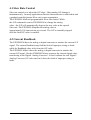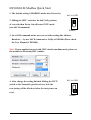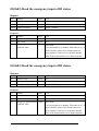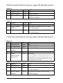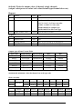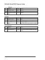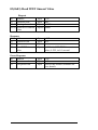
1
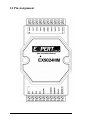
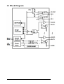
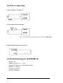
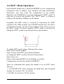
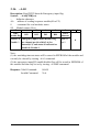
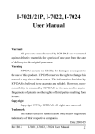
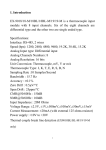
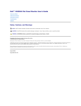
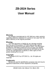
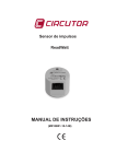
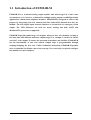
1.1 Introduction of EX9024H-M
EX9024H-M is a 4-channel analog output module with mixed type I/O. Under some
circumstances, it is, however, a demand for multiple analog outputs to fulfill particular
applications without many duplicate modules. EX9024H-M is designed to achieve this
purpose by integrating four A/O channels and four isolated D/I channels into only one
module. The four digital input channels function as an interlock for emergency latch
output. The LED indicators are used for status reading and both ASCII and
Modbus-RTU protocols are supported.
EX9024H-M provide multi-range A/O support, allows its four A/O channels working at
the same time with different and more output ranges. For example, it can have 0~20 mA
and ±10 V at its output. To ensure the operation of machines and facilities, EX9024H-M
has the functionality of slew rate control. Output slope is programmable through
ramping/clamping the slew rate. Unlike traditional mechanism, EX9024H-M permits
users to substitute its default value at the start up. Users can easily set up and configure
the module to be more adaptive.
EX9024H-M User Manual Rev:A.1
1
Specifications:
◆
◆
◆
◆
Support Protocol: ASCII and MODBUS-RTU
Interface: RS-485, 2 wires
Speed (bps): 1200, 2400, 4800, 9600, 19.2K, 38.4K , 115.2K
Analog output :
◇ Output type: mA, V
◇ Analog Channels Numbers: 4
◇ Analog Resolution: 14 bits
◇ Output Range: 0~20 mA, 4~20 mA, 0~+5V, ±5V, 0~+10V and ±10V
◇ Programmable Output Slope : 0.125 to 2048 mA/Second
0.0625 to 1024 V/Second
◇ Current Load Resistor: External 24V/1050 ohms
◇ Accuracy : ±0.1% of FSR for current output
±0.2% of FSR for voltage output
◇ Zero Drift: Voltage output : ±30µV/°C
◆
◆
◆
◆
◆
Current output : ±0.2µA/°C
◇ Span Temperature Coefficient: ±25 ppm/°C
◇ Isolation voltage : 3000VDC
Isolation Digital Input:
◇ Channel: 4(Sigle Ended w/ Common Source)
◇ Logical level 0: +1V max.
◇ Logical level 1: +10 ~ +30Vdc
◇ Isolation voltage : 3750Vrms
Watchdog Function:
◇ Host programmable watchdog: 100 ms ~ 25.500 sec
Overvoltage protection: ±35V
Power input : +10V to +30VDC
Consumption: 2.4W
EX9024H-M User Manual Rev:A.1
2
1.2 Pin Assignment
EX9024H-M User Manual Rev:A.1
3
1.3 Block Diagram
EX9024H-M User Manual Rev:A.1
4
1.4 Wire Connection
Voltage output wire connection
Vout N
V
AGND
Load
Current output wire connection
Load
I
Iout N
AGND
Note : External Power setting, may drive load up to 1050 ohms.
Isolation digital input wire connection
DI.COM
DIn
1.5 Default Setting for EX9024H-M
Address:01
Analog O/P Type: 0 ~ +10V
Analog O/P slew rate: Immediate change
Baudrate : 9600bps
Checksum: disable
Protocol: Modbus
EX9024H-M User Manual Rev:A.1
5
1.6 INIT* Mode Operation
Each EX9000 module has a build-in EEPROM to store configuration
information such as address, type, baudrate and other information.
Sometimes, user may forget the configuration of the module.
Therefore, the EX9000 have a special mode named "INIT* mode" to
help user to resolve the problem. The "INIT* mode" is setting as
Address=00, Baudrate=9600bps, no Checksum .
Originally, the INIT* mode is accessed by connecting the INIT*
terminal to the GND terminal. New EX9000 modules have the INIT*
switch located on the rear side of the module to allow easier access to
the INIT* mode. For these modules, INIT* mode is accessed by
sliding the INIT* switch to the Init position as shown below.
To enable INIT* mode, please following these steps:
Step1. Power off the module
Step2. Connect the INIT* pin with the GND pin.
(or sliding the INIT* switch to the Init* ON position)
Step3. Power on
Step4. Send command $002 (cr) in 9600bps to read the
Configuration stored in the module's EEPROM.
There are commands that require the module to be in INIT* mode.
They are:
1. %AANNTTCCFF when changing the Baud Rate and checksum
settings. See Section 3.20.1 for details.
2. $AAPN, See Section 3.20.8 for details.
EX9024H-M User Manual Rev:A.1
6
1.7 Module Status for DIO, AIO
Power On Reset or Module Watchdog Reset will let all
output goto Power On Value. And the module may accept the host's
command to change the output value.
Host Watchdog Timeout will let all output goto Safe Value.
The module's status(read by command~AA0) will be 04, and the
output command will be ignored.
1.8 Dual Watchdog Operation for DIO, AIO
Dual Watchdog=Module Watchdog + Host Watchdog
The Module Watchdog is a hardware reset circuit to monitor
the module's operating status. While working in harsh or noisy
environment, the module may be down by the external signal. The
circuit may let the module to work continues and never halt.
The Host Watchdog is a software function to monitor the host's
operating status. Its purpose is to prevent the network from
communication problem or host halt. When the timeout interval
expired, the module will turn all outputs to predefined Safe Value.
This can prevent the controlled target from unexpected situation.
The EX9000 module with Dual Watchdog may let the control
system more reliable and stable.
1.9 Reset Status
The Reset Status is set while the module power on or reset by module
watchdog and is cleared while the command read Reset Status ($AA5)
applied. This is useful for user to check the module's working status.
When the Reset Status is set means the module is reset and the output
may be changed to the PowerOn Value. When the Reset Status is clear
means the module is not rested and the output is not changed.
EX9024H-M User Manual Rev:A.1
7
1.10 Digital O/P
The module's output have 3 different situation :
<1>Safe Value. If the host watchdog timeout status is set, the
output is set to Safe Value. While the module receive the output
command like @AA(Date) or #AABBDD, the module will ignore the
command and return "!". And will not change the output to the output
command value. The host watchdog timeout status is set and store
into EEPROM while the host watchdog timeout interval expired
and only can be cleared by command ~AA1. If user want to change
the output it need to clear the host watchdog timeout status firstly and
send output command to change the output into desired value.
<2>PowerOn Value. Only the module reset and the host
watchdog timeout status is clear, the module's output is set to
predefined Power On Value.
<3> Output Command Value. If the host watchdog timeout
status is clear and user issue a digital output command like @AA
(Data) or #AABBDD to module for changing the output value. The
module will response success (receive>).
1.11 Latch Digital I/P
For example, use connect the key switch to Digital input channel of a
digital input/output module and want to read the key stoke. The Key
input is a pulse digital input and user will lost the strike. While
reading by command $AA6 in A and B position, the response is that
no key stroke and it will lose the key stroke information. Respectely,
the read latch low digital input command $AAL0 will solve this
problem. When issue $AAL0 command in A and B position, the
response denote that there is a low pulse between A and B position
for a key stroke.
EX9024H-M User Manual Rev:A.1
8
1.12 Calibration
The current calibration procedure is as follows :
1. Connect meter and external power source to module’s current output
channel N.
2. Warm up the module for 30 minutes.
3. Setting type to 30 (0 to 20mA) by command "$AA9NTTSS" (see p22)
4. Output 0mA by analog output command "#AAN(data)” (see p13)
5. Check the meter and trim the output until 0mA match by apply trim
command "$AA3NVV" (see p44)
6. Repeat step(5) for trim calibration.
7. Perform 0mA calibration command for save min. calibration parameter.
by command "$AA0N" (see p14)
8. Output 20mA by analog output command "#AAN(data)" (see p13)
9. Check the meter and trim the output until 20mA match by apply trim
command "$AA3NVV" (see p16)
10. Repeat step(9) for trim calibration.
11. Perform 20mA calibration command for save min. calibration
parameter. by command "$AA1N" (see p15)
12. Repeat steps 4 to 11 three times.
Warning: Please don’t calibrate before you really understand.
EX9024H-M User Manual Rev:A.1
9
The voltage calibration procedure is as follows :
1. Connect meter to module’s Voltage output channel N.
2. Warm up the module for 30 minutes.
3. Setting type to 33 (-10V to +10V) by command "$AA9NTTSS" (see p22)
4. Output -10V by analog output command "#AAN(data)" (see p13)
5. Check the meter and trim the output until -10V match by apply trim
command "$AA3NVV" (see p16)
6. Repeat step(5) for trim calibration.
7. Perform -10V calibration command for save min. calibration parameter.
by command "$AA0N" (see p14)
8. Output +10V by analog output command "#AAN(data)" (see p13)
9. Check the meter and trim the output until +10V match by apply trim
command "$AA3NVV" (see p16)
10. Repeat step(9) for trim calibration.
11. Perform +10V calibration command for save min. calibration parameter
by command "$AA1N" (see p15)
12. Repeat steps 4 to 11 three times.
Warning: Please don’t calibrate before you really understand.
EX9024H-M User Manual Rev:A.1
10
2. Configuration Table
Analog O/P type code setting(TT)
TT
Rang
Format
MAX
MIN
Engineer Unit +20.000 +00.000
Hexadecimal
3FFF
0
Engineer Unit +20.000 +04.000
31 4 ~ 20 mA
Hexadecimal
3FFF
0
Engineer Unit +10.000 +00.000
32 0 ~ 10 V
Hexadecimal
3FFF
0
-10 ~ +10 Engineer Unit +10.000 -100.000
33
V
Hexadecimal
3FFF
C000
Engineer Unit +05.000 +00.000
34 0 ~ +5 V
Hexadecimal
3FFF
0
Engineer Unit +05.000 -05.000
35 -5 ~ +5 V
Hexadecimal
3FFF
C000
Note: Hexadecimal format only for Modbus RTU mode
Engineer Unit format only for ASCII command mode
30 0 ~ 20 mA
Baudrate Setting(CC)
CC Baud Rate
03 1200 BPS
04 2400 BPS
05 4800 BPS
06 9600 BPS
07 19200 BPS
08 38400 BPS
09 57600 BPS
0A 115200 BPS
EX9024H-M User Manual Rev:A.1
11
Output
Resolution
2.4414µA
1.2207µA
2.4414µA
0.9766µA
1.2207mV
0.6104mV
1.2207mV
0.6104mV
1.2207mV
0.3052mV
1.2207mV
0.3052mV
Data Format(FF)
7
6
Set to 0 Checksum
(CRC in Modbus)
0=disable
1=enable
5
4
3
2
1
0
Slew Rate Control set to 0000 00:engineeringunit
Slew Rate Control ref. sec. 4.1
Slew Rate Control(SS)
Slew rate
V/Sec.
mA/Sec.
00
Immediate
01
0.0625
0.125
02
0.125
0.25
03
0.25
0.5
04
0.5
1.0
05
1.0
2.0
06
2.0
4.0
07
4.0
8.0
08
8.0
16.0
09
16.0
32.0
0A
32.0
64.0
0B
64.0
128.0
0C
128.0
256.0
0D
256.0
512.0
0E
512.0
1024.0
0F
1024.0
2048.0
EX9024H-M User Manual Rev:A.1
12
3. ASCII Command
3.1
#AAN(data)
Description: Output Analog Value for Channel N
Syntex: #AAN(data)[CHK](cr)
#
delimiter character
AA address of reading/response module(00 to FF)
(data): Analog Output Value
N=Channel No. (from 0 to 3)(data)
Response: Valid Command:
>
Out of range:
?AA
Command ignore:
!
Example:
Command: #010+12.345 Receive: >
Module address 01, Channel 0 Current output : 12.345mA
Command: #023-02.500 Receive: >
Module address 02, Channel 3 voltage output: -2.5V
Command: #020+30.000 Receive: ?02
Out of range and output value will go to the most close value
EX9024H-M User Manual Rev:A.1
13
3.2
$AA0N
Description: Perform -10V/0mA calibration for channel N.
Syntax: $AA0N[CHK](cr)
$
delimiter character
AA address of reading/response module(00 to FF)
0
command for perform 4mA (or 0mA/-10V) calibration
N=Channel No. (0 to 3)
Response: Valid Command:
!AA
Invalid Command:
?AA
Example:
Command: $0201 Receive: !02
Module address 02, Channel 1, perform -10V/0mA for EX9024H-M
calibration.
Warning: Please don’t calibrate before you really understand.
EX9024H-M User Manual Rev:A.1
14
3.3
$AA1N
Description: Perform +10V/20mA calibration for channel N
Syntax: $AA1N[CHK](cr)
$
delimiter character
AA address of reading/response module(00 to FF)
1
command for performing 20mA/+10V calibration
N
channel to calibration (0 to 3)
Response: Valid Command:
!AA
Invalid Command:
?AA
Example
Command: $0112 Receive: !01
Module address 01, channel 2, perform +10V/20mA calibration
Command: $2010 Receive: !02
Module address 02, channel 0, perform +10V/20mA calibration.
Warning: Please don’t calibrate before you really understand.
EX9024H-M User Manual Rev:A.1
15
3.4
$AA3NVV
Description: Trim the analog output for calibration for channel N.
Syntax: $AA3NVV[CHK](cr)
$
delimiter character
AA address of reading/response module(00 to FF)
3
command for trimming calibration
N
channel to trim (0 to 3)
VV 2’complement hexadecimal to trim the analog output value,
00 to 5F: increase analog output 0 to 95 counts
FF to A1: decrease analog output 1 to 95 counts
Each count indicates 2.44uA or 1.22mV
Response: Valid Command:
Invalid Command:
!AA
?AA
Example:
Command: $013202 Receive: !01
For channel 2, to increase analog output 2 count=2*2.44 uA or 2*1.22
mV, depend on output type.
Warning: Please don’t calibrate before you really understand.
EX9024H-M User Manual Rev:A.1
16
3.5
$AA4N
Description: Set Power-on value for channel N.
Syntax: $AA4N[CHK](cr)
$
delimiter character
AA address of reading/response module(00 to FF)
4
command for set the output value to Power-on value
N
channel to set Power-on value (0 to 3)
Response: Valid Command:
!AA
Invalid Command:
?AA
Example:
Command: #020-01.234 Receive: >
Channel 0 analog output -1.234V
Command: $0240 Receive: !02
To set the Power-on value for channel 0 as -1.234V
EX9024H-M User Manual Rev:A.1
17
3.6
$AA6N
Description: Last value Readback of Channel N
Syntax: $AA6N[CHK](cr)
$
delimiter character
AA address of reading/response module(00 to FF)
6
command for read last output command value
N
Channel to readback (0 to 3)
Response: Valid Command:
!AA(Data)
Invalid Command:
?AA
(Data)
the last output command value. If no output applied to the
module that the (data) is the Power-on value of the module
Example:
Command: #010+12.345 Receive:>
The analog output for channel 0 is 12.345mA
Command: $0160 Receive: !010+12.345
Last output command value 12.345mA
EX9024H-M User Manual Rev:A.1
18
3.7
$AA7N
Description: Read the power-on output value of channel N.
Syntax: $AA7N[CHK](cr)
$
delimiter character
AA address of reading/response module(00 to FF)
7
command for read power-on value
N
channel to readback (0 to 3)
Response: Valid Command:
!AA(Data)
Invalid Command:
?AA
(Data)
the last output command value
Example:
Command: #020-01.234 Receive: >
Channel 0 analog output –1.234V
Command: $0240
Receive: !02
To set power-on value for channel 0 as –1.234V
Command: #020-03.456 Receive: >
Channel 0 analog output –3.456V
Command: $0270
Receive: !02-01.234
The read power-on value of channel 0 is –1.234V
Command: $0260
Receive: !02-03.456
The last output value of channel 0 is –3.456V
EX9024H-M User Manual Rev:A.1
19
3.8
$AA8N
Description: Current Value Readback of Channel N .
When sending a command to assign the analog output value for a specific
channel of EX9024H-M. The analog output is updated gradually at the specific
slew rate until the desired output value is reached. This command can read the
analog value during updating process.
Syntax: $AA8N[CHK](cr)
$
delimiter character
AA address of reading/response module(00 to FF)
7
command for read Current Value Readback of Channel N
N
channel to readback (0 to 3)
Response: Valid Command:
!AA(Data)
Invalid Command:
?AA
(Data)
the last output command value
Example:
Command: $012 Receive: !0132060C
The configuration for this EX9024H-M as follows:
Output range: 0 to 10V, slew rate: 0.25V/sec
Checksum: Disable
Command: #010+01.000 Receive:>
Set channel 0 output value to 1.000V
Command: #010+09.800 Receive:>
Set channel 0 output value to 9.800V
Command: $0180 Receive:!01+01.372
Read back value is 1.372V
Command: $0180 Receive:!01+04.821
The reading back value is 4.821V
Command: $0180 Receive:!01+06.772
The reading back value is 6.772V
Command: $0180 Receive:!01+08.291
The reading back value is 8.291V
Command: $0180 Receive: !01+09.800
The reading back value is 9.800V
EX9024H-M User Manual Rev:A.1
20
3.9
$AA9N
Description: Read DA Configuration of Channel N
Syntax: $AA9N[CHK](cr)
$
delimiter character
AA address of reading/response module(00 to FF)
8
command for read DA configuration of channel N
N
channel to read DA configuration (0 to 3)
Response: Valid Command:
!AATTSS
Invalid Command:
?AA
the last output command value
TT analog output Type ref. sec. 2 for format
SS analog output Slew rate ref. sec. 2 for format
Example:
Command: $0190
Receive: !013000
Read address 01 channel 0 DA configuration & 0 to 20mA output Type
and change immediate .
EX9024H-M User Manual Rev:A.1
21
3.10
$AA9NTTSS
Description: Set DA Configuration of Channel N
Syntax: $AA9NTS[CHK](cr)
$
delimiter character
AA address of reading/response module(00 to FF)
9
command for set DA configuration
N
channel to set DA configuration (0 to 1)
TT
analog output Type ref. sec. 2 for format
SS
analog output Slew rate ref. sec. 2 for format
Response: Valid Command:
!AA
Invalid Command:
?AA
Example:
Command: $01913301
Receive: !01
Set address 01 channel 1 DA configuration & 0 to 10V output Type and
Slew rate 0.0625 V/Second .
EX9024H-M User Manual Rev:A.1
22
3.11
~AA4N
Description: Read the safe value of channel N.
Syntax: ~AA4N[CHK](cr)
~
delimiter character
AA address of reading/response module(00 to FF)
4
command for read Safe Value
N
channel to read (0 to 3)
Response: Valid Command:
!AA(Data)
Invalid Command:
?AA
(Data)
Save Value of module
Example:
Command: ~0140 Receive: !01+02.000
The safe value of channel 0 is 2.000V
Command: ~0141 Receive: !01+01.234
The safe value of channel 1 is 1.234V
EX9024H-M User Manual Rev:A.1
23
3.12
~AA5N
Description: Set Safe Value of Channel N.
Syntax: ~AA5N[CHK](cr)
~
delimiter character
AA address of reading/response module(00 to FF)
5
command for store current output value as Safe Value
N
channel to set (0 to 3)
Response: Valid Command:
!AA(Data)
Invalid Command:
?AA
Example:
Command: #010+12.345 Receive: !01
Output channel 0 address 01 value as +12.345mA
Command: ~0150 Receive: !01
To set Safe Value of Channel 0 address 01 to 12.345mA
EX9024H-M User Manual Rev:A.1
24
3.13
~AA8NE
Description: Enable/Disable Emergency Input(DI).
Syntax: ~AA8NE[CHK](cr)
~
delimiter character
AA address of reading/response module(00 to FF)
8
command for set Emergency DI input
N
channel to set (0 to 3)
E
Disable/Enable emergency inputs (DI)
0 : Disable / 1 : Enable
Response: Valid Command:
Invalid Command:
!AA
?AA
Note:
(1) When a emergency input(DI) is active(low), the module will be forced to safety
output state for channel N of A/O.
(2) If disable is selected then emergency input(DI) same as standard digital input.
Example:
Command: #041+01.000 Response: >
Output address 04 value +01.000V for channel 1, return success.
Command: ~0451(cr) Response: !01
Set address 04 channel 1 Safe Value, return success.
Command: ~04181 (cr) Response: !04
Set module (ID=04) to enable channel(1) emergency inputs.
Command: ~040(cr) Response: !0410
Read module status from module (ID=04) and return the channel(1)
emergency Input is enable.
wait………
The modules emergency Input(DI) channel(1) is active(low) and the AO channel
N of the module is into safe output mode.
;
Command: @040(cr) Response: !040D
Read Emergency Input port status from module (ID=04) and return the
emergency input channel(1) is active(low).
Command: #041+01.000 Response: !
Output address 04 value +01.000V for channel 1, return emergency input
is active and the output command will be ignored.
EX9024H-M User Manual Rev:A.1
25
3.14
@AA
Description: Read Emergency digital input status.
Syntax: @AA[CHK](cr)
@
delimiter character
AA address of reading/response module(00 to FF)
Response: Valid Command:
Invalid Command:
>00(Data)
?AA
Note: The Data are in two hexadecimal digitals format.
Module
EX9024H-M
Data
DI0~DI3
00~07
Example:
Command: @01 Receive: >0005
Read address 01 digital input status and return Dl(0,2) high level and
Dl(1,3) low level.
EX9024H-M User Manual Rev:A.1
26
3.15
~**
Description: Host OK.
Host send this command to all modules for send the information “Host OK”.
Syntax: ~**[CHK](cr)
~
delimiter character
** command for all modules
Response: No response
Example:
Command: ~** Receive: No response
Send Host OK to all modules.
EX9024H-M User Manual Rev:A.1
27
3.16
~AA0
Description: Read WDT Status & Emergency input flag.
Syntax: ~AA0[CHK](cr)
~
delimiter character
AA address of reading/response module(00 to FF)
0
command for read modules status
SS Module status (Hex)
7
6
5
4
3
WDT
DI3
DI2
DI1
DI0
enable flag
Disable: 0 Emergency input Enable/Disable flag,
Enable: 1 one channel per bit of bit(3~6) for
channel(0~3) and status is indicated as:
Disable:0, Enable:1
2
WDT
timeout
Clear: 0
Set: 1
1
0
0
Note:
(1) the watchdog timeout status will be stored in EEPROM of the module and
can only be cleared by issuing ~AA1 command.
(2) the emergency input(DI) enable/disable flag will be stored in EEPROM of
the module and can only be set by issuing ~AA8NE command.
Response: Valid Command:
Invalid Command:
!AASS
?AA
EX9024H-M User Manual Rev:A.1
28
3.17
~AA1
Description: Reset Module Status.
Syntax: ~AA1[CHK](cr)
~
delimiter character
AA address of reading/response module(00 to FF)
1
command for reset modules status
Response: Valid Command:
!AA
Invalid Command:
?AA
EX9024H-M User Manual Rev:A.1
29
3.18
~AA2
Description: Read Host Watchdog Timeout Value
Syntax: ~AA2[CHK](cr)
~
delimiter character
AA address of reading/response module(00 to FF)
2
command for read host watchdog timeout value
Response: Valid Command:
!AAEVV
Invalid Command:
?AA
E
VV
Host watchdog enable status, 1=Enable, 0=Disable.
Timeout value in HEX format, Each count is 0.1 second, 01=0.1 second
and FF=25.5 seconds.
EX9024H-M User Manual Rev:A.1
30
3.19
~AA3EVV
Description: Set host watchdog Timeout value
Syntax: ~AA3EVV[CHK](cr)
~
delimiter character
AA address of reading/response module(00 to FF)
3
command for set host watchdog timeout value
E
1=Enable/0=Disable host watchdog
VV timeout value, from 01 to FF, each for 0.1 second
Response: Valid Command:
!AA
Invalid Command:
?AA
Example:
Command: ~010
Receive: !0100
Read address 01 modules status, return host watchdog timeout status is
clear.
Command: ~013164
Receive: !01
Set address 01 host watchdog timeout value 10.0 seconds and enable
host watchdog, return success.
Command: ~012
Receive: !01164
Read address 01 host watchdog timeout value, return that host watchdog
is enabled, and time interval is 10.0 seconds.
Command: ~**
No response
Reset the host watchdog timer.
Wait for about 10 seconds and don’t send command ~**, the LED of
module will go to flash. The flash LED indicates the host watchdog
timeout status is set.
Command: ~010
Receive: !0104
Read address 01 module status, return host watchdog timeout status is
set.
Command: ~012
Receive: !01064
Read address 01 host watchdog timeout value, return that host watchdog
is disabled, and time intervals is 10.0 seconds.
Command: ~011
Receive: !01
Reset address 01 host watchdog timeout status, return success and the
LED of this module stop flash.
Command: ~010
Read address 01 module status, return host watchdog timeout status is
clear.
EX9024H-M User Manual Rev:A.1
31
3.20
General Command Sets
3.20.1 %AANNTTCCFF
Description: Set Module Configuration
Syntax: %AANNTTCCFF[CHK](cr)
%
delimiter character
AA address of reading/response module(00 to FF)
NN new address for setting response module(00 to FF)
TT new type for setting module (sec. 2 for format)
CC new baudrate for setting module. (sec. 2)
It is needed to short the INIT* to ground while change baudrate.
FF new data format for setting module. (sec. 2 for format)
It is needed to short the INIT* to ground to change checksum setting.
Response: Valid Command:
!AA
Invalid Command:
?AA
Example:
Command: %0102300600 Receive: !02
Set module address 01 to 02,
Analog output type: 0 to 20mA
Baudrate: 9600bps
Dataformat: No checksum, Engineer unit, slew rate is immediate
return success.
EX9024H-M User Manual Rev:A.1
32
3.20.2 $AA2
Description: Read Configuration
Syntax: $AA2[CHK](cr)
$
delimiter character
AA address of reading/response module(00 to FF)
2
command for read configuration
Response: Valid Command:
!AATTCCFF
Invalid Command:
?AA
TT
type code of module (sec. 2 for format)
CC
baudrate code of module (sec. 2 for format)
FF
data format of module (sec. 2 for format)
Example:
Command: $012 Receive: !01306000
Read address 01 status, return
Analog output type: 0 to 20mA
Baudrate: 9600bps
Dataformat: No checksum, Engineer unit, slew rate is immediate
EX9024H-M User Manual Rev:A.1
33
3.20.3 $AA5
Description: Read Reset Status
Syntax: $AA5[CHK](cr)
$
delimiter character
AA address of reading/response module(00 to FF)
5
command for read reset status
Response: Valid Command:
!AAS
Invalid Command:
?AA
S
reset status, 1= the module is been reset,
0= the module is not been reseted
Example:
Command: $015 Receive: !011
Read address 01 reset status, return first read.
Command: $015 Receive: !010
Read address 01 reset status, return no reset occurred.
EX9024H-M User Manual Rev:A.1
34
3.20.4
$AAF
Description: Read Firmware Version
Syntax: $AAF[CHK](cr)
$
delimiter character
AA address of reading/response module(00 to FF)
F
command for read firmware version
Response: Valid Command:
!AA(Data)
Invalid Command:
?AA
(Data)
firmware version of module
Example:
Command: $01F Receive: !01R1.4
Read address 01 firmware version, return version R1.4.
Command: $02F Receive: !01A1.4
Read address 02 firmware version, return version A1.4.
EX9024H-M User Manual Rev:A.1
35
3.20.5
$AAM
Description: Read Module Name
Syntax: $AAM[CHK](cr)
$
delimiter character
AA address of reading/response module(00 to FF)
M
command for read module name
Response: Valid Command:
!AA(Data)
Invalid Command:
?AA
(Data)
Name of module
Example:
Command: $01M Receive: !019021
Read address 01 module name, return name 9021.
Command: $03M Receive: !029024
Read address 03 module name, return name 9024
EX9024H-M User Manual Rev:A.1
36
3.20.6
~AAO(Data)
Description: Set Module Name
Syntax: ~AAO(Data)[CHK](cr)
~
delimiter character
AA address of reading/response module(00 to FF)
O
command for set module name
(Data) new name for module, max 6 characters
Response: Valid Command:
!AA
Invalid Command:
?AA
Example:
Command: ~01O9024 Receive: !01
Set address 01 module name 9084, return success.
Command: $01M Receive: !019024
Read address 01 module name, return name 9024
EX9024H-M User Manual Rev:A.1
37
3.20.7
$AAP
Description: Read protocol information of Module
Syntax: $AAP[CHK](cr)
$
delimiter character
AA
address of reading/response module (00 to FF)
P
command for read protocol information of module
Response:
S
Valid Command:
!AAS
Invalid Command:
?AA
The protocol supported by the module
10: the protocol set in EEPROM is Normal mode
11: the protocol set in EEPROM is ModbusRTU mode
Example:
Command: $01P
Receive: !0110
Reads the communication protocol of module 01 and returns a response of 10
meaning the protocol that will be used at the next power on reset is normal mode.
Command: $01P1
Receive: !01
Sets the communication protocol of module 01 to Modbus RTU and returns a valid
response. And the next power on reset is in ModbusRTU mode.
EX9024H-M User Manual Rev:A.1
38
3.20.8
$AAPN
Description: Set the protocol information of Module
Syntax: $AAPN[CHK](cr)
$
delimiter character
AA
address of reading/response module (00 to FF)
P
command for set protocol information of module
N
The protocol supported by the module
0: the protocol set in EEPROM is Normal mode
1: the protocol set in EEPROM is ModbusRTU mode
Before using this command, it is needed to short the INIT* to ground (or
sliding the INIT* switch to the Init ON position of rear side). The new
protocol is saved in the EEPROM and will be effective after the next
power-on reset.
Response:
Valid Command:
!AA
Invalid Command:
?AA
Example:
Command: $01P1
Receive: !01
Sets the communication protocol of module 01 to Modbus RTU and returns a valid
response. And the next power on reset is in ModbusRTU mode.
EX9024H-M User Manual Rev:A.1
39
4.1 Slew Rate Control
Slew rate control is to adjust the O/P slope . Most analog O/P change is
instantaneously . In many applications that this characteristics is undesirable and
a gradual controlled output Slew rate is more appropriate.
The EX9024H-M allows programmable Slew rate control. While
the O/P command is sent to EX9024H-M to change the analog
value , the O/P will automatically slope to the new value at the special
Slew rate .The EX9024H-M update the analog value at
approximately 100 conversions per second . The O/P is smoothly stepped
until the final O/P value is reached .
4.2 Current Readback
The EX9024H-M have the analog to digital converter to monitor the current O/P
signal . The current Readback may find the fault of improper wiring or loads
while thr Readback value is far from the O/P value .
The EX9024H-M don’t have the analog to digital converter to monitor the
current O/P signal . But the EX9024H-M may response the current digital value
transferring to the Digital /Analog Converter . It can’t indicate the real Digital /
Analog Converter O/P value and can’t detect the fault of improper wiring or
loads .
EX9024H-M User Manual Rev:A.1
40
EX9024H-M Modbus Quick Start
1. The default setting is MODBUS mode after Power On.
Init* to GND
ON
2. Sliding the INIT* switch to the Init*(ON) position
of rear side then Power On will enter INIT* mode
1
(use ASCII command).
Normal
3. On ASCII command mode, user can set other setting like Address,
Baudrate, …by use ASCII command or Utility of EX9000 (Please check
the User Manual of EX9000).
Note: If your application need with CRC check in modbus mode, please set
the module to checksum(CRC) enable.
Init* to GND
4. After change the setting finished, Sliding the INIT*
ON
switch to the Normal(1) position of rear side, the
new setting will be effectived after the next power-on
reset.
1
Normal
EX9024H-M User Manual Rev:A.1
41
01(0x01) Read the protocol.
Request
00
Address
1 Byte
1-247
01
Function code
1 Byte
0x01
02~03 Starting channel
2 Bytes 0x0100
04~05 Channel numbers
2 Bytes 0x0001
Response
00
Address
1 Byte
1-247
01
Function code
1 Byte
0x01
02
Byte count
1 Byte
0x01
03
Protocol read back
value
1 Byte
0x00=ASCII
0x01=Modbus RTU
05(0x05) Set the protocol.
Request
00
Address
1 Byte
1-247
01
Function code
1 Byte
0x05
02~03 Starting channel
2 Bytes 0x0100
04~05 Channel numbers
2 Bytes 0x0000=ASCII
0xFF00=Modbus RTU
Response
00
Address
1 Byte
1-247
01
Function code
1 Byte
0x05
02
Byte count
1 Byte
0x01
03
Protocol read back
value
2 Byte
The value is the same as byte 04 and 05 of the
Request
EX9024H-M User Manual Rev:A.1
42
02(0x02) Read the emergency input of DI status
Request
00
Address
1 Byte
1-247
01
Function code
1 Byte
0x02
02~03 Starting channel
2 Bytes 0x0020~0x0023
04~05 Channel numbers
2 Bytes 0x0001~0x0004
Response
00
Address
1 Byte
1-247
01
Function code
1 Byte
0x02
02
Byte count
1 Byte
0x01
03
Emergency input channel 1 Byte
read back value
0x00~0x0F
A bit corresponds to a channel. When the bit is 1 it
denotes that the value of the channel that was
Input response. if the bit is 0 it denotes that the
value of the channel that was no Input response .
03(0x03) Read the emergency input of DI status
Request
00
Address
1 Byte
1-247
01
Function code
1 Byte
0x03
02~03 Starting channel
2 Bytes 0x0020~0x0023
04~05 Channel numbers
2 Bytes 0x0001~0x0004
Response
00
Address
1 Byte
1-247
01
Function code
1 Byte
0x03
02
Byte count
1 Byte
0x01
03
Emergency input channel 1 Byte
read back value
0x00~0x0F
A bit corresponds to a channel. When the bit is 1 it
denotes that the value of the channel that was
Input response. if the bit is 0 it denotes that the
value of the channel that was no Input response .
EX9024H-M User Manual Rev:A.1
43
01(0x01) Read the emergency input of DI flag
Request
00
Address
1 Byte
1-247
01
Function code
1 Byte
0x01
02~03 Starting channel
2 Bytes 0x08C0~0x08C3
04~05 Channel numbers
2 Bytes 0x0001~0x0004
Response
00
Address
1 Byte
1-247
01
Function code
1 Byte
0x01
02
Byte count
1 Byte
0x01
03
Emergency input flag
read back value
1 Byte
0x00~0x0F
A bit corresponds to a channel. When the
bit is 1 it denotes that the value of the
channel that was Input response. if the bit
is 0 it denotes that the value of the channel
that was no Input response .
EX9024H-M User Manual Rev:A.1
44
05(0x05) Set enable/disable the emergency input of DI flag (Single channel)
Request
00
Address
01
Function code
02~03 Channel number
04~05 Channel value
1 Byte
1 Byte
2 Bytes
2 Bytes
1-247
0x05
0x08C0~0x08C3
0xFF00 for enable
0x0000 for disable
Response
00
Address
01
Function code
02~03 Output channel
numbers
04~05 Output value
1 Byte 1-247
1 Byte 0x05
2 Bytes The value is the same as byte 02 and
03 of the Request
2 Bytes The value is the same as byte 04 and
05 of the Request
15(0x0F) Set enable/disable the emergency input of DI flag (Multi channel)
Request
00
Address
01
Function code
02~03 Starting channel
04~05 Output channel
numbers
06
Byte count
07
Output
value/Clear DI
count value
1 Byte
1 Byte
2 Bytes
2 Bytes
1-247
0x0F
0x08C0~0x08C3
0x0001~0x0004
1 Byte
1 Byte
1
0x00~0x0F
A bit corresponds to a channel. When the bit is 1 it
denotes that the value of the channel that was set is
ON. if the bit is 0 it denotes that the value of the
channel that was set is OFF.
Response
00
Address
01
Function code
02~03 Starting channel
04~05 Output channel
numbers
1 Byte 1-247
1 Byte 0x0F
2 Bytes The value is the same as byte 02 and
03 of the Request
2 Bytes The value is the same as byte 04 and
05 of the Request
EX9024H-M User Manual Rev:A.1
45
03(0x03) Read the output value of channel
(output value/power on value/ safe value/channel type/channel slew rate)
Request
00
Address
1 Byte
1-247
01
Function code
1 Byte
0x03
02~03 Starting channel
2 Bytes 0x0000~0x0003 for Output value
0x00C0~0x00C3 for Power on value
0x0BB8~0x0BBB for Safe value
0x0100~0x0103 for Output type
0x0120~0x0123 for Slew rate type
04~05 Channel numbers
2 Bytes 0x0001~0x0004
Response
00
Address
1 Byte
1-247
01
Function code
1 Byte
0x03
02
Byte count
1 Byte
N* x 2
03
Emergency input channel 1 Byte
read back value
Refer the table as follow
N*=Number of output channels
Output type & Data Format Table
Type Code
Output Range
Data Format
Max.
Min.
0x0030
0 to 20mA
Hexadecimal
0x3FFF
0x0000
0x0031
4 t0 20 mA
Hexadecimal
0x3FFF
0x0000
0x0032
0 to 10V
Hexadecimal
0x3FFF
0x0000
0x0033
-10V to +10V
Hexadecimal
0x3FFF
0xC000
0x0034
0 to +5V
Hexadecimal
0x2FFF
0x0000
0x0035
-5V to +5V
Hexadecimal
0x2FFF
0xC000
**Channel output value should be in hexadecimal form and should between range of
maximum & minimum value that depend on each type code.
Slew rate table.
0x0000
V/sec
0x0001 0x0002 0x0003 0x0004 0x0005 0x0006 0x0007
0.0625
0.125
0.25
0.5
1.0
2.0
4.0
0.125
0.25
0.5
1.0
2.0
4.0
8.0
0x0008
0x0009
0x000A 0x000B 0x000C 0x000D 0x000E
V/sec
8.0
16.0
32.0
64.0
128.0
256.0
512.0
1024.0
mA/sec
16.0
32.0
64.0
128.0
256.0
512.0
10024.0
2048.0
mA/sec
Immediate
EX9024H-M User Manual Rev:A.1
46
0x000E
06(0x06) Write the output value of channel (single channel)
(output value/power on value/ safe value/channel type/channel slew rate)
Request
00
Address
1 Byte
1-247
01
Function code
1 Byte
0x06
02~03 Starting channel
2 Bytes 0x0000~0x0003 for Output value
0x00C0~0x00C3 for Power on value
0x0BB8~0x0BBB for Safe value
0x0100~0x0103 for Output type
0x0120~0x0123 for Slew rate type
04~05 Output channel value
2 Bytes Refer the table as follow
Response
00
Address
1 Byte
1-247
01
Function code
1 Byte
0x06
02
Starting channel
2 Byte
Same as byte 02 and 03 of the Request
03
Output channel value
2 Byte
Same as byte 04 and 05 of the Request
Output type & Data Format Table
Type Code
Output Range
Data Format
Max.
Min.
0x0030
0 to 20mA
Hexadecimal
0x3FFF
0x0000
0x0031
4 t0 20 mA
Hexadecimal
0x3FFF
0x0000
0x0032
0 to 10V
Hexadecimal
0x3FFF
0x0000
0x0033
-10V to +10V
Hexadecimal
0x3FFF
0xC000
0x0034
0 to +5V
Hexadecimal
0x2FFF
0x0000
0x0035
-5V to +5V
Hexadecimal
0x2FFF
0xC000
**Channel output value should be in hexadecimal form and should between range of
maximum & minimum value that depend on each type code.
Slew rate table.
0x0000
V/sec
0x0001 0x0002 0x0003 0x0004 0x0005 0x0006 0x0007
0.0625
0.125
0.25
0.5
1.0
2.0
4.0
0.125
0.25
0.5
1.0
2.0
4.0
8.0
0x0008
0x0009
0x000A 0x000B 0x000C 0x000D 0x000E
V/sec
8.0
16.0
32.0
64.0
128.0
256.0
512.0
1024.0
mA/sec
16.0
32.0
64.0
128.0
256.0
512.0
10024.0
2048.0
mA/sec
Immediate
EX9024H-M User Manual Rev:A.1
47
0x000E
16(0x10) Write the output value of channel (Multiple channel)
(output value/power on value/ safe value/channel type/channel slew rate)
Request
00
Address
1 Byte
1-247
01
Function code
1 Byte
0x10
2 Bytes
0x0000~0x0003 for Output value
0x00C0~0x00C3 for Power on value
0x0BB8~0x0BBB for Safe value
02~03 Starting channel
0x0100~0x0103 for Output type
0x0120~0x0123 for Slew rate type
04~05 Output channel numbers 2 Bytes
0x0000~0x0004
06
Byte count
1 Byte
2 x N*
07~
Output channel value
N* x 2 Byte
Refer the table as follow
N*= Output channel numbers
Response
00
Address
1 Byte
1-247
01
Function code
1 Byte
0x10
2 Bytes
Same as byte 02 and 03 of the Request
04~05 Output channel numbers 2 Bytes
Same as byte 04 and 05 of the Request
02~03 Starting channel
Output type & Data Format Table
Type Code
Output Range
Data Format
Max.
Min.
0x0030
0 to 20mA
Hexadecimal
0x3FFF
0x0000
0x0031
4 t0 20 mA
Hexadecimal
0x3FFF
0x0000
0x0032
0 to 10V
Hexadecimal
0x3FFF
0x0000
0x0033
-10V to +10V
Hexadecimal
0x3FFF
0xC000
0x0034
0 to +5V
Hexadecimal
0x2FFF
0x0000
0x0035
-5V to +5V
Hexadecimal
0x2FFF
0xC000
**Channel output value should be in hexadecimal form and should between range of
maximum & minimum value that depend on each type code.
Slew rate table.
0x0000
V/sec
0x0001 0x0002 0x0003 0x0004 0x0005 0x0006 0x0007
0.0625
0.125
0.25
0.5
1.0
2.0
4.0
0.125
0.25
0.5
1.0
2.0
4.0
8.0
0x0008
0x0009
0x000A 0x000B 0x000C 0x000D 0x000E
V/sec
8.0
16.0
32.0
64.0
128.0
256.0
512.0
1024.0
mA/sec
16.0
32.0
64.0
128.0
256.0
512.0
10024.0
2048.0
mA/sec
Immediate
EX9024H-M User Manual Rev:A.1
48
0x000E
06(0x06) Write the Module address/baudrate
Request
00
Address
1 Byte
1-247
01
Function code
1 Byte
0x06
02~03 Starting channel
2 Bytes 0x01E4 for Address
0x01E5 for Baudrate
04~05 Output channel value
2 Bytes 0x0000~0x00FF for address
Baudrate Refer the table as follow
Response
00
Address
1 Byte
1-247
01
Function code
1 Byte
0x06
02
Starting channel
2 Byte
Same as byte 02 and 03 of the Request
03
Output channel value
2 Byte
Same as byte 04 and 05 of the Request
Baudrate Setting
Baud Rate
0x0003
1200 BPS
0x0004
2400 BPS
0x0005
4800 BPS
0x0006
9600 BPS
0x0007
19200 BPS
0x0008
38400 BPS
0x0009
57600 BPS
0x000A
115200 BPS
EX9024H-M User Manual Rev:A.1
49
01(0x01) Read WDT timeout status
Request
00
Address
01
Function code
02~03 Starting channel
04~05 Read WDT timeout
status
1 Byte
1 Byte
2 Bytes
2 Bytes
1-247
0x01
0x010D
0x0001
Response
00
Address
01
Function code
02
Byte count
03
Read WDT timeout
status
1 Byte
1 Byte
1 Byte
1 Byte
1-247
0x01
1
0x00 The WDT timeout status is clear
0x01 The WDT timeout status is enable
1 Byte
1 Byte
1 Byte
1-247
0x81
Refer to the Modbus standard for more
details.
Error Response
00
Address
01
Function code
02
Exception code
EX9024H-M User Manual Rev:A.1
50
03(0x03) Read WDT timeout Value
Request
00
Address
01
Function code
02~03 Starting channel
04~05 Read WDT timeout
value
1 Byte
1 Byte
2 Bytes
2 Bytes
1-247
0x03
0x01E8
0x0001
Response
00
Address
01
Function code
02
Byte count
03~ Read WDT timeout
value
1 Byte
1 Byte
1 Byte
1 Byte
1-247
0x03
2
0x0000~0x00FF WDT timeout
value, 0~255, in 0.1 second
1 Byte
1 Byte
1 Byte
1-247
0x83
Refer to the Modbus standard for
more details.
Error Response
00
Address
01
Function code
02
Exception code
EX9024H-M User Manual Rev:A.1
51
03(0x03) Send Host OK
Request
00
Address
01
Function code
02~03 Starting channel
04~05 Send Host OK
1 Byte
1 Byte
2 Bytes
2 Bytes
1-247
0x03
0x3038
0x0000
No Response
04(0x04) Send Host OK
Request
00
Address
01
Function code
02~03 Starting channel
04~05 Send Host OK
1 Byte
1 Byte
2 Bytes
2 Bytes
1-247
0x04
0x3038
0x0000
No Response
EX9024H-M User Manual Rev:A.1
52
05(0x05) Set WDT timeout /Clear WDT timeout status
Request
00
Address
01
Function code
02~03 WDT timeout
04~05 WDT timeout
Response
00
Address
01
Function code
02~03 WDT timeout
04~05 WDT timeout
00
01
02
Error Response
Address
Function code
Exception code
1 Byte 1-247
1 Byte 0x05
2 Bytes 0x0104 Set WDT timeout
enable/disable
0x010D Clear WDT timeout status
2 Bytes 0xFF00 for WDT timeout enable
0x0000 for WDT timeout disable
0xFF00 for Clear WDT timeout
status
1 Byte 1-247
1 Byte 0x05
2 Bytes The value is the same as byte 02 and
03 of the Request
2 Bytes The value is the same as byte 04 and
05 of the Request
1 Byte
1 Byte
1 Byte
1-247
0x85
Refer to the Modbus standard for
more details.
EX9024H-M User Manual Rev:A.1
53
06(0x06) Set WDT timeout Value
Request
00
Address
01
Function code
02~03 Starting channel
04~05 WDT timeout value
1 Byte
1 Byte
2 Bytes
2 Bytes
1-247
0x06
0x01E8
0x0000~0x00FF WDT timeout
value, 0~255, in 0.1 second
Response
00
Address
1 Byte 1-247
01
Function code
1 Byte 0x06
02~03 WDT timeout value 2 Bytes The value is the same as byte 02 and
03 of the Request
04~05 WDT timeout value 2 Bytes The value is the same as byte 04 and
05 of the Request
Error Response
00
Address
01
Function code
02
Exception code
1 Byte
1 Byte
1 Byte
1-247
0x86
Refer to the Modbus standard for
more details.
EX9024H-M User Manual Rev:A.1
54
Modbus Mapping Table:
ADDR
00257
00261
00270
00273
02241
Item
Protocol, ASCII & Modbus select.
For function (0x01) : = 1 - Modbus RTU
For function (0x05) :
0xFF00 = Modbus RTU
0x0000 = ASCII
For function (0x0F) : 1 = Modbus RTU.
Host watchdog enable/disable
For function (0x01) : = 1 - enable
For function (0x05) : 0xFF00 = enable
For function (0x0F) : 1 = enable.
Host watchdog timeout status
For function (0x01) : = 1 - set
For function (0x05) : 0xFF00 = clear
For function (0x0F) : 1 = clear
Read module reset status
= 1 - first read after powered on
= 0 - not the first read after powered on
Enable/Disable DI0 Emergency input flag.
For function (0x01) : 1 = enable
For function (0x05) : 0xFF00 = enable
For function (0x0F) : 1 = enable.
Attribute
R/W
R/W
R/W
R
R/W
02242
Enable/Disable DI1 Emergency flag
R/W
02243
02244
Enable/Disable DI2 Emergency flag
Enable/Disable DI3 Emergency flag
R/W
R/W
ADDR
10033
10034
10035
10036
Item
Attribute
Read Emergency DI0 Input channel.
1 = input high level (ON )
0 = input low level (OFF )
Read Emergency DI1 Input channel.
Read Emergency DI2 Input channel.
Read Emergency DI3 Input channel..
EX9024H-M User Manual Rev:A.1
R
R
R
R
55
ADDR
40001
40002
40003
40004
40193
40194
40195
40196
43001
43002
43003
43004
40257
40258
40259
40260
40289
40290
40291
40292
40489
40492
40485
40486
Item
Attribute
Current analog output value of channel 0
Error Response (offset 02):
= 0x00 - valid command
= 0x02 - invalid start address
= 0x03 - invalid data value
= 0x04 - host WDT timeout
= 0x05 - return if Emergency DI flag is active
Current analog output value of channel 1
Current analog output value of channel 2
Current analog output value of channel 3
Power on analog output value of channel 0
Power on analog output value of channel 1
Power on analog output value of channel 2
Power on analog output value of channel 3
Safe value of analog output channel 0
Safe value of analog output channel 1
Safe value of analog output channel 2
Safe value of analog output channel 3
Type code channel(0)
Type code channel(1)
Type code channel(2)
Type code channel(3)
slew rate control for channel 0
slew rate control for channel 1
slew rate control for channel 2
slew rate control for channel 3
Host watchdog timeout value (0~255, in 100ms)
Host watchdog timeout count, write 0 to clear
Module address, valid range: 1 ~ 247
Baudrate setting(CC)
EX9024H-M User Manual Rev:A.1
56
R/W
R/W
R/W
R/W
R/W
R/W
R/W
R/W
R/W
R/W
R/W
R/W
R/W
R/W
R/W
R/W
R/W
R/W
R/W
R/W
R/W
R/W
R/W
R/W