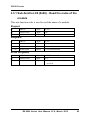
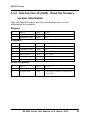
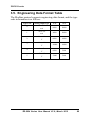
1
ZB-2024 Series
User Manual
Warranty
All products manufactured by ICP DAS are under warranty
regarding defective materials for a period of one year from the
date of delivery to the original purchaser.
Warning
ICP DAS assumes no liability for any damage resulting
from the use of this product. ICP DAS reserves the right to
change this manual at any time without notice. The information
furnished by ICP DAS is believed to be accurate and reliable.
However, no responsibility is assumed by ICP DAS for its use,
nor for any infringements of patents or other rights of third
parties resulting from its use.
Copyright
Copyright © 2012 by ICP DAS Co., Ltd. All rights are
reserved.
Trademarks
Names are used for identification purposes only and may be
registered trademarks of their respective companies.
ZB-2024 Series User Manual V1.0, March 2012
1
Table of Contents
1.
Introduction................................................................................................................................................ 4
1.1.
Pin Assignments ................................................................................................................................ 5
1.2.
Specifications ..................................................................................................................................... 6
1.3.
Wire Connections .............................................................................................................................. 8
1.4.
Quick Start ......................................................................................................................................... 9
1.5.
Switch Descriptions ......................................................................................................................... 10
1.6.
Connection ....................................................................................................................................... 13
1.7.
INIT Mode ....................................................................................................................................... 16
1.8.
Type and Data Format Tables......................................................................................................... 17
1.9.
Calibration ....................................................................................................................................... 19
1.9.1
1.10.
2.
Analog Output............................................................................................................................ 19
Technical Support............................................................................................................................ 20
DCON Protocol ........................................................................................................................................ 21
2.1.
%AANNTTCCFF ............................................................................................................................ 25
2.2.
#AAN(Data) ..................................................................................................................................... 27
2.3.
$AA0N.............................................................................................................................................. 29
2.4.
$AA1N.............................................................................................................................................. 31
2.5.
$AA2................................................................................................................................................. 33
2.6.
$AA3NVV ........................................................................................................................................ 35
2.7.
$AA4N.............................................................................................................................................. 37
2.8.
$AA5................................................................................................................................................. 39
2.9.
$AA6N.............................................................................................................................................. 41
2.10.
$AA7N.............................................................................................................................................. 43
2.11.
$AA8N.............................................................................................................................................. 45
2.12.
$AA9N.............................................................................................................................................. 47
2.13.
$AA9NTS ......................................................................................................................................... 49
2.14.
$AAB ................................................................................................................................................ 51
ZB-2024 Series User Manual V1.0, March 2012
2
3.
4.
2.15.
$AAF ................................................................................................................................................ 53
2.16.
$AAM ............................................................................................................................................... 54
2.17.
$AAS1 .............................................................................................................................................. 55
2.18.
~**.................................................................................................................................................... 57
2.19.
~AA0 ................................................................................................................................................ 58
2.20.
~AA1 ................................................................................................................................................ 60
2.21.
~AA2 ................................................................................................................................................ 62
2.22.
~AA3EVV ........................................................................................................................................ 64
2.23.
~AA4N ............................................................................................................................................. 66
2.24.
~AA5N ............................................................................................................................................. 68
2.25.
~AA6PN(Data) ................................................................................................................................ 70
2.26.
~AA6SN(Data)................................................................................................................................. 72
2.27.
~AAEV ............................................................................................................................................. 74
2.28.
~AAO(Data) ..................................................................................................................................... 76
Modbus RTU Protocol............................................................................................................................. 78
3.1.
Function 06 (0x06) - Set an Analog Output Channel .................................................................... 79
3.2.
Function 16 (0x10) - Read the analog output Channels ................................................................ 80
3.3.
Function 70 (0x46) - Read/Write Module Settings......................................................................... 81
3.3.1
Sub-function 00 (0x00) - Read the name of the module.......................................................... 82
3.3.2
Sub-function 32 (0x20) - Read the firmware version information......................................... 83
3.4.
Address Mappings............................................................................................................................ 84
3.5.
Engineering Data Format Table..................................................................................................... 86
Troubleshooting ....................................................................................................................................... 87
4.1.
5.
Communicating with the module .................................................................................................... 87
Appendix ................................................................................................................................................... 88
5.1.
Dual Watchdog Operation............................................................................................................... 88
ZB-2024 Series User Manual V1.0, March 2012
3
1. Introduction
The ZB-2000 series is a family of wireless ZigBee data
acquisition modules that provide analog-to-digital, digital-to-analog,
digital input/output, timer/counter and other functions. These modules
can be remotely controlled using a set of DCON or Modbus RTU
commands. The ZB-2024 series provide 4-channel analog output that
can be configured via hardware. Refer to Section 1.5 “Switch
Descriptions” for details.
The ZB-2000 series modules are not able to operate as standalone
modules and need to be connected to a ZigBee host device, such as
the ZB-2550(P)(-T) or the ZB-2570(P)(-T), in order to communicate
with the other ZB-2000 series modules. For more information, refer
to the “ZigBee Converter Quick Start“ guide available at the
following address:
http://ftp.icpdas.com/pub/cd/usbcd/napdos/zigbee/zigbee_converter/
ZB-2024 Series User Manual V1.0, March 2012
4
1.1. Pin Assignments
ZB-2024 Series
ZB-2024 Series User Manual V1.0, March 2012
5
1.2. Specifications
Models
ZB-2024-T
ZB-2024-PA
Analog Output
Output Channels
4
Output Type
0 ~ +10 VDC, -10 VDC ~ +10 VDC,
0 ~ +5 VDC, -5 VDC ~ +5 VDC,
0 ~ +20 mA, +4 mA ~ +20 mA
Resolution
12-bit
Accuracy
+/-0.1% of FSR
Zero Drift
+/-30 µV/°C
Span Drift
+/-25 ppm/°C
Programmable Output Slope
0.125 to 2048 mA/ second
0.0625 to 1024 V/ second
Voltage Output Capability
10 V @10 mA
Current Load Resistance
External +24 V power : 1050 Ohms
Power-on and Safe Values
Yes
Intra-module Isolation, Field
to Logic
2500 VDC
ESD Protection
+/-4 kV Contact for each channel
Communication Interface
Wireless
ZigBee, IEEE 802.15.4 Standard
Transmission power
4 dBm
22 dBm
Antenna 2.4 GHz-
3 dBi Omni-Directional
antenna
5 dBi Omni-Directional
antenna
Transmission range (LOS)
100 m
700 m(Typical) 1
km(Max.)
Certification
CE/FCC,FCC ID
No
Max. Slaves in a zigbee network
254
ZB-100R/ZB-100T Supported
Yes
Protocols
Supports DCON and Modbus RTU Protocols
Hot Swap
By Rotary and DIP switch
ZB-2024 Series User Manual V1.0, March 2012
6
LED Indicators
Power
1 LED, red
ZigBee Communication
1 LED, green
Powe
Power Consumption
2.3 W max.
Mechanical
Flammability
Fire Retardant Materials (UL94-V0 Level)
Dimensions (W x L x H)
33 mm x 87 mm x 107 mm
Installation
DIN-Rail
Environment
Operating Temperature
-25 °C ~ +75 °C
Storage Temperature
-30 °C ~ +80 °C
Humidity
10 ~ 90% RH, non-condensing
ZB-2024 Series User Manual V1.0, March 2012
7
1.3.
Wire Connections
ZB-2024 Series
ZB-2024 Series User Manual V1.0, March 2012
8
1.4. Quick Start
This Quick Start document describes the methods used to
quickly set up and test ZB-2000 series modules using the ICP DAS
DCON Utility.
First, you must set the ZigBee configuration of
ZB-2570(P)(-T)/ZB-2550(P)(-T) before using any ZB-2000 modules
because the ZB-2570(P)(-T)/ZB-2550(P)(-T) is a ZigBee Net Server.
For more information about the ZB-2570(P)(-T)/ZB-2550(P)(-T),
please refer to the “ZigBee Converter Quick Start“ quide available at
the following address:
http://ftp.icpdas.com/pub/cd/usbcd/napdos/zigbee/zigbee_converter
If you have already installed the ZB-257x/ZB-255x series
Utility, you only need to set the “PAN ID” and the “ZB RF Channel”
for the ZB-2570(P)(-T)/ZB-2550(P)(-T) so that it is the same as the
ZB-AIO setting. The ZB-AIO will then operate correctly.
1
ZB-2024 Series User Manual V1.0, March 2012
9
1.5. Switch Descriptions
The ZB-2024 series module contains 12 dip switch and a Rotary
switch that are used to configure the module.
The following gives a description of the function and usage of each
dip switch:
1. Address: The module address is defined using two components.
The first is dip switch 1 and the second is a 16-position rotary
switch. The address is a hexadecimal value that allows you set
addresses mapping from 0x01 to 0x1F (0x00 is used for
initialization mode). Dip switch 1 is used to define the high 4 bits
of the address value, and the 16-position rotary switch is used to
define the low 4 bits of the address.
The address value is equal to the ZigBee PAN ID value. A unique
Node ID should be set for all ZigBee slave devices, such as
ZigBee IO modules, ZigBee converters and ZigBee repeaters.
The ZB-2024 series module will switch to INIT mode when the
address value is 0. Refer to Section 1.7 “INIT Mode” for more
information.
2. Protocol: Dip switch 2 is used to define the protocol. When set to
the ON position, it means that the “Modbus RTU” protocol will be
enabled, and when set to the OFF position, it denotes that the
“DCON” protocol will be used.
3. Checksum: Dip switch 3 is used to define whether a checksum
will be used. When set to the ON positon, the checksum will be
enabled, and when set to the OFF position, the checksum will be
ZB-2024 Series User Manual V1.0, March 2012
10
disabled. This option is only effective when the DCON protocol is
enabled.
4. PAN ID: Dip switch 4 is used to define the ZigBee network PAN
ID. Only the values 0xFF00 or 0xFF01 are valid for ZigBee IO
series module. 0xFF01 is selected by moving the dip switch to the
ON position and 0xFF00 is selected by moving the dip switch to
the OFF position.
5. Channel: Dip switches 5-7 are used to define the ZigBee
operating channel. The configuration is as follows:
Switch Value
Channel
Switch Value
Channel
Switch Value
Channel
0
1
2
3
4
9
14
15
6. Hardware configuration: Dip switch 8 is used to define whether
the type code of the ZB-2024 series module is to be configured
using firmware or hardware. The ON position indicates that
configuration is via hardware, and the OFF position denotes that
configuration is performed via firmware. The differences between
firmware and hardware configuration are as follows:
Type Code is set to firmware
Type Code is set to hardware
configuration
configuration
Allows different type codes to be set
All channels will use the same type code
for each channel.
that is defined using the values set via dip
switches 10-12.
The type code value is configured with The type code value is configured based
the value stored in EEPROM.
on the dip switch of the ZB-2024 series.
The data format is configured using
The data format is configured using a dip
software commands.
switch. Data format configuration
commands are ignored in this mode.
ZB-2024 Series User Manual V1.0, March 2012
11
When a command is used to read the When a command is used to read the
current type code, the value that is
current type code, the value that has been
stored in the EEPROM of the ZB-2024 configured via dip switches of the
series will be returned.
ZB-2024 series will be returned.
7. Data Format: Dip switch 9 is used to define the data format used by the
ZB-2024 series modue. The ON position indicates that hex format will be used,
and the OFF position indicates engineering format will be used. This dip switch is
only applicable when the “Hardware configuration” dip switch is in the ON
position.
8. Type Code: Dip switches 10-12 are used to define the input type code for the
ZB-2024 series module, as shown below.
ZB-2024 Series
Switch Value
Type Code
Switch Value
Type Code
Switch Value
Type Code
0x00
0x01
0x02
0x03
0x04
0x05
0x05
0x05
ZB-2024 Series User Manual V1.0, March 2012
12
1.6. Connection
A ZigBee host must already exist in a ZigBee network. If you
want to communicate with ZB-2000 IO modules, you need to use a
ZB-2550(P)(-T) or a ZP-2570(P) host o connect to your controller.
To create a ZigBee network, the “Channel” and “PAN ID”
parameters of all ZigBee modules should be individually configured
to the same value.
For instance, use the software utility to configure the PAN ID of
the ZB-2550(P)(-T) as 0xFF00 and the Channel as 0. Then set dip
switches 4-7 on the ZB-2024 series module to the OFF position to set
the PAN ID to 0xFF00 and the Channel to 0. Based on the above
configuration, the ZB-2550(P)(-T) host and the ZB-2024 series
module will then be able to communicate with each other. Set dip
switches 2 and 3 to the OFF position to set the protocol for the
module to DCON and disable the checksum.
Moving the rotary switch on the ZB-2024 series module to
position 1 will set the module address to 0x01. You can then use the
“DCON Utility” on the Host PC that is connected to the
ZB-2550(P)(-T) host to send a command to the ZB-2024 series
module. The response you receive should be similar to that shown
below:
!01Z2024
ZB-2024 Series User Manual V1.0, March 2012
13
The ZB-2024 series is a command-based data acquisition
module. A number of commands are provided that can be used to
configure and set the analog output. Refer to Section 2 for details.
The ZB-2024 series module also support the Modbus RTU
protocol. The configuration command format for the Modbus RTU is
as follows:
*n: This value depends on the Sub-function code.
Eg: To set channels 0, 1, 2 and 3 to enabled and channels 4, 5, 6
and 7 to disabled, the following command should be sent:
01 46 26
0F
BA
69
The supported analog I/O commands are as follows:
Function Code
Description
0x01
Read coils
0x02
Read discrete inputs
0x03
Read multiple registers
0x04
Read multiple input registers
0x05
Write single coils
0x0F
Write multiple coils
Eg: To read the current analog input value for channels 0 to 7, the
following command should be sent:
01 03 00 00 00 07 04 08
Eg: To set the filter to 50Hz, the following command should be
sent:
01 05 01 02 FF 00 2C 06
To install the ZigBee analog I/O module, follow the steps below:
1. Connect the analog input.
ZB-2024 Series User Manual V1.0, March 2012
14
2. Connect the ZigBee analog I/O module to the power supply
using the +Vs and GND terminals.
3. In order to output the analog output channels when using the
DCON protocol, send a #AAN(Data) command to the module.
See Section 2.2 for details. When using the Modbus RTU
protocol, use the Function 06h or 10h to set the output for
channels. See Sections 3.1 and Section 3.2 for details.
ZB-2024 Series User Manual V1.0, March 2012
15
1.7. INIT Mode
Each ZigBee module has an internal EEPROM that is used to
store its configuration, such as it’s address, ZigBee PAN ID, ZigBee
channel numbers, etc. If you forget the module’s configuration
information, you can use INIT mode to reset the ZB-2024 series
module to the default settings, then you can re-configure the module.
To change to INIT mode, you only need to adjust the address value to
0.
The default settings for ZB analog I/O modules are:
Protocol: DCON
Module Address: 0
Checksum: Disabled
ZB-2024 Series User Manual V1.0, March 2012
16
1.8. Type and Data Format Tables
Type Code Output Type
0
1
2
3
4
5
0 to +20
mA
+4 to +20
mA
0 to +10
V
-10 to +10
V
0 to +5
mV
-5 to +5
V
Data Format
+F.S.
-F.S.
Engineering units
+20.000 +00.000
% of FSR
+100.00 +000.00
2’s comp HEX
FFFF
0000
Engineering units
+20.000 +04.000
% of FSR
+100.00 +000.00
2’s comp HEX
FFFF
0000
Engineering units
+10.000 +00.000
% of FSR
+100.00 +000.00
2’s comp HEX
FFFF
0000
Engineering units
+10.000
-10.000
% of FSR
+100.00
-100.00
2’s comp HEX
7FFF
8000
Engineering units
+5.0000 +0.0000
% of FSR
+100.00 +000.00
2’s comp HEX
FFFF
0000
Engineering units
+5.0000
-5.0000
% of FSR
+100.00
-100.00
2’s comp HEX
7FFF
8000
ZB-2024 Series User Manual V1.0, March 2012
17
Slew Rate Control
0
1
2
3
4
5
6
7
8
9
A
B
C
D
E
F
Immediate chang
0.0625 V/Second or 0.125 mA/Second
0.125 V/Second or 0.25 mA/Second
0.25 V/Second or 0.5 mA/Second
0.5 V/Second or 1.0 mA/Second
1.0 V/Second or 2.0 mA/Second
2.0 V/Second or 4.0 mA/Second
4.0 V/Second or 8.0 mA/Second
8.0 V/Second or 16 mA/Second
16 V/Second or 32 mA/Second
32 V/Second or 64 mA/Second
64 V/Second or 128mA/Second
128 V/Second or 256 mA/Second
256 V/Second or 512 mA/Second
512 V/Second or 1024 mA/Second
1024 V/Second or 2048 mA/Second
Data Format Settings (FF)
7
6
Reserved
CS
Key
Description
DF
Data Format
5
4
3
Reserved
2
1
0
DF
00: Engineering units
01: % of FSR
10: 2’s Complement Hexadecimal
CS
Checksum Settings
0: Disabled
1: Enabled
Note: Reserved bits should be zero.
ZB-2024 Series User Manual V1.0, March 2012
18
1.9. Calibration
Warning: Performing calibration is not recommended until the
process is fully understood.
1.9.1 Analog Output
The calibration procedure is as follows:
1. Warm up the module for 30 minutes.
2. Set the type code to the type you want to calibrate. Refer to
Section 2.13 for details.
3. Enable calibration. Refer to Section 2.26 for details.
4. Set the analog output to zero. Refer to Section 2.2 for details.
5. Check the meter and trim the output until zero output. Refer to
Section 2.6 for details.
6. Send the analog output zero calibration command. Refer to Section
2.3 for details.
7. Set the span analog output. Refer to Section 2.2 for details.
8. Check the meter and trim the output until the span output. Refer to
Section 2.11 for details.
9. Send the analog output span calibration command. Refer to
Section 2.4 for details.
Notes:
1. Connect the calibration voltage to the specific channel you are
calibrating.
2. Calibration voltages and currents are shown below.
Calibration voltages:
Type Code
0
1
2
3
4
5
Zero
Output
0 mA
4mA
0V
0V
0V
0V
Span
Output
+20 mV
+20 mA
+10 V
+10 V
+5 V
+5 V
ZB-2024 Series User Manual V1.0, March 2012
19
1.10.Technical Support
Should you encounter any problems while using the ZB-2024 series
module, and are unable to find the help you need in this manual or on
our website, please contact ICP DAS Product Support.
Email: [email protected]
Website: http://www.icpdas.com/service/support.htm
When requesting technical support, be prepared to provide the
following information about your system:
1. Module name and serial number: The serial number can be found
printed on the barcode label attached to the cover of the module.
2. Firmware version: See Sections 2.14 and 3.3.2 for information
regarding the command used to identify the firmware version.
3. Host configuration (type and operating system)
4. If the problem is reproducible, please give full details describing
the procedure used to reproduce the problem.
5. Any specific error messages displayed. If a dialog box with an
error message is displayed, please include the full text of the dialog
box, including the text in the title bar.
6. If the problem involves other programs or hardware devices, please
describe the details of the problem in full.
7. Any comments and suggestions related to the problem are
welcome.
ICP DAS will reply to your request by email within three business
days.
ZB-2024 Series User Manual V1.0, March 2012
20
2. DCON Protocol
All communication with ZB analog I/O modules consists of
commands generated by the host and responses transmitted by the ZB
analog I/O module. Each module has a unique ID number that is used
for addressing purposes and is stored in non-volatile memory. The ID
is 01 by default and can be changed by transmitting the prescribed
user command. All commands to the modules contain the ID address,
meaning that only the addressed module will respond. The only
exception to this is command ~**(Section 2.17) which is sent to all
modules, but in this case, the modules do not reply to the command.
Command Format:
Leading
Character
Module
Address
Command
[CHKSUM]
CR
Data
[CHKSUM]
CR
Response Format:
Leading
Character
Module
Address
CHKSUM A 2-character checksum which is present when the
checksum setting is enabled. See Section 1.8 (Type and
Data Format Settings) for details.
CR
End of command character, carriage return (0x0D)
ZB-2024 Series User Manual V1.0, March 2012
21
Checksum Calculation:
1. Calculate the ASCII code sum of all the characters in the
command/response string, except for the carriage return character
(CR).
2. The checksum is equal to the sum masked by 0FFh.
Example:
Command string: $012(CR)
1. Sum of the string = “$”+”0”+”1”+”2” = 24h+30h+31h+32h = B7h
2. Therefore the checksum is B7h, and so CHKSUM = “B7”
3. The command string with the checksum = $012B7(CR)
Response string: !01200600(CR)
1. Sum of the string = “!”+”0”+”1”+”2”+”0”+”0”+”6”+”0”+”0” =
21h+30h+31h+32h+30h+30h+36h+30h+30h = 1AAh
2. Therefore the checksum is AAh, and so CHKSUM = “AA”
3. The response string with the checksum = !01200600AA(CR)
Note:
All characters should be in upper case.
ZB-2024 Series User Manual V1.0, March 2012
22
General Command Sets
Command
Response
%AANNTTCCFF !AA
Description
Sets the configuration of the module
Sets the analog output of a specific
Section
2.1
#AAN(Data)
>
$AA0N
!AA
Performs an analog output zero calibration
2.3
$AA1N
!AA
Performs an analog output span calibration
2.4
$AA2
!AANNTTCCFF Reads the configuration of the module
2.5
$AA3NVV
!AA
Trims the analog output calibration
2.6
$AA4N
!AA
Sets the analog output power-on value
2.7
$AA5
!AAS
Reads the reset status of the module
2.8
$AA6N
!AA(Data)
Reads the last analog output value
2.9
$AA7N
!AA(Data)
Reads the analog output power-on value
2.10
$AA8N
!AA(Data)
Reads the current analog output value
2.11
$AA9N
!AATS
Reads the analog output configurations
2.12
$AA9NTS
!AA
Set the analog output configurations
2.13
$AAB
!AA
Detects the status of the wire connection
2.14
$AAF
!AA(Data)
Reads the firmware version information
2.15
$AAM
!AA(Data)
Reads the name of the module
2.16
$AAS1
!AA
Reloads the default calibration parameters
2.17
~AAEV
!AA
Enables/Disables calibration
2.27
~AAO(Data)
!AA
Sets the name of the module
2.28
channel
2.5
Host Watchdog Command Sets
Command
Response
Description
Section
~**
No Response
Informs all modules that the host is OK
2.18
~AA0
!AASS
Reads the status of the Host Watchdog
2.19
~AA1
!AA
Resets the status of the Host Watchdog
2.20
~AA2
!AAETT
Reads the Host Watchdog timeout settings
2.21
~AA3EVV
!AA
Sets the Host Watchdog timeout settings
2.22
~AA4N
!AA(Data)
~AA5N
!AA
Reads the analog output safe value for a
specific channel
Sets the analog output safe value for a
ZB-2024 Series User Manual V1.0, March 2012
2.23
2.24
23
specific channel
~AA6PN(Data)
!AA
~AA6SN(Data)
!AA
Sets the analog output power-on value
directly for a specific channel
Sets the analog output safe value directly
for a specific channel
ZB-2024 Series User Manual V1.0, March 2012
2.25
2.26
24
ZB-2024 series
2.1. %AANNTTCCFF
Description:
This command is used to set the configuration for a specified
module.
Syntax:
%AANNTTCCFF[CHKSUM](CR)
%
AA
NN
TT
CC
FF
Delimiter character
The address of the module to be configured in hexadecimal
format (00 to 1F)
The new address of the module in hexadecimal format (00
to 1F)
Not used by the ZB-2024 series module (Reserved) and
should be set 00
Not used by the ZB-2024 series module (Reserved) and
should be set 00
The command used to set the data format, checksum and
filter settings for the module, See Section 1.8 for details.
Response:
Valid Response:
!AA[CHKSUM](CR)
Invalid Response:
?AA[CHKSUM](CR)
!
Delimiter for a valid response
?
Delimiter for an invalid response
AA
The address of the responding module in hexadecimal
format (00 to 1F)
There will be no response if the command syntax is incorrect, there
is a communication error, or there is no module with the specified
address.
ZB-2024 Series User Manual V1.0, March 2012
25
ZB-2024 series
Examples:
Command: %0202000A80
Response: !02
Sets the data format for module 02 to 80 (50Hz rejection) and
engineering data format, and returns a valid response.
Related Commands:
Section 2.5 $AA2
Related Topics:
Section 1.8 Type and Data Format Tables
ZB-2024 Series User Manual V1.0, March 2012
26
ZB-2024 series
2.2. #AAN(Data)
Description:
This command is used to set the analog output value for channel N
of a specified module.
Syntax:
#AAN(Data)[CHKSUM](CR)
#
AA
N
(Data)
Delimiter character
The address of the module to be set in hexadecimal format
(00 to 1F)
The channel to be set, zero based
The analog output value, see Section 1.8 for details of the
data format
Response:
>
?
!
Delimiter character for a valid response
Delimiter character for an invalid response indicating that
the output value is out of range. The output will revert to
the closest value set in the module’s output range.
Delimiter character for an invalid response indicating that
the module’s Host Watchdog flag has been set. The output
command will be ignored and the output will be set to the
safe value.
There will be no response if the command syntax is incorrect, there
is a communication error, or there is no module with the specified
address.
ZB-2024 Series User Manual V1.0, March 2012
27
ZB-2024 series
Examples:
Command: $0190300
Response: !01
Reads the configuration of module 01 and returns a valid
response indicating an output type of 0 to 20mA and any
changes are immediate.
Command: #010+05.000
Response: >
Sets the output value for channel 0 of module 01 to 5.0 mA and
returns a valid response.
Command: #010+25.000
Response: ?
Attempts to set the output value for channel 0 of module 01 to
25.0 mA, but returns an invalid response because the output
value is out of range.
Related Commands:
Section 2.1 %AANNTTCCFF, Section 2.5 $AA2
Related Topics:
Section 1.8 Type and Data Format Tables
ZB-2024 Series User Manual V1.0, March 2012
28
ZB-2024 series
2.3. $AA0N
Description:
This command is used to perform an analog output zero calibration
on channel N of a specified module.
Syntax:
$AA1[CHKSUM](CR)
$
AA
0
N
Delimiter character
The address of the module to be calibrated in hexadecimal
format (00 to 1F)
The command to perform the analog output zero
calibration
The channel to be calibrated, zero based
Response:
Valid Response:
!AA[CHKSUM](CR)
Invalid Response:
?AA[CHKSUM](CR)
!
Delimiter character for a valid response
?
Delimiter character for an invalid response
AA
The address of the responding module in hexadecimal
format (00 to 1F)
There will be no response if the command syntax is incorrect, there
is a communication error, or there is no module with the specified
address.
ZB-2024 Series User Manual V1.0, March 2012
29
ZB-2024 series
Examples:
Command: $0101
Response: ?01
Attempts to send the command to perform an analog output
zero calibration on channel 1 of module 01, but returns an
invalid response because the “enable calibration” command,
~AAEV, was not sent in advance.
Command: ~01E1
Response: !01
Enables calibration on module 01 and returns a valid response.
Command: $0101
Response: !01
Sends the command to perform an analog output zero
calibration on channel 1 of module 01 and returns a valid
response.
Related Commands:
Section 2.4 $AA1N, Section 2.6 $AA3NVV, Section 2.27 ~AAEV
Related Topics:
Section 1.9 Calibration
ZB-2024 Series User Manual V1.0, March 2012
30
ZB-2024 series
2.4. $AA1N
Description:
This command is used to perform an analog output span calibration
on channel N of a specified module.
Syntax:
$AA1N[CHKSUM](CR)
$
AA
1
N
Delimiter character
The address of the module to be calibrated in hexadecimal
format (00 to 1F)
The command to perform the analog output span
calibration
The channel to be calibrated, zero based
Response:
Valid Response:
!AA[CHKSUM](CR)
Invalid Response:
?AA[CHKSUM](CR)
!
Delimiter character for a valid response
?
Delimiter character for an invalid response
AA
The address of the responding module in hexadecimal
format (00 to 1F)
There will be no response if the command syntax is incorrect, there
is a communication error, or there is no module with the specified
address.
ZB-2024 Series User Manual V1.0, March 2012
31
ZB-2024 series
Examples:
Command: $0111
Response: ?01
Attempts to send the command to perform a span calibration on
channel 1 of module 01, but returns an invalid response
because the “enable calibration” command, ~AAEV, was not
sent in advance.
Command: ~01E1
Response: !01
Enables calibration on module 01 and returns a valid response.
Command: $0111
Response: !01
Sends the command to perform a span calibration on channel 1
of module 01 and returns a valid response.
Related Commands:
Section 2.3 $AA0N, Section 2.6 $AA3NVV, Section 2.27 ~AAEV
Related Topics:
Section 1.9 Calibration
ZB-2024 Series User Manual V1.0, March 2012
32
ZB-2024 series
2.5. $AA2
Description:
This command is used to read the configuration of a specified
module.
Syntax:
$AA2[CHKSUM](CR)
$
AA
2
Delimiter character
The address of the module to be read in hexadecimal
format (00 to 1F)
The command to read the configuration of the mdoule
Response:
Valid Response:
!AATTCCFF[CHKSUM](CR)
Invalid Response:
?AA[CHKSUM](CR)
!
Delimiter character for a valid response
?
Delimiter character for an invalid response
AA
The address of the responding module in hexadecimal
format (00 to 1F)
TT
Not used by the ZB-2024 series module and should be 00
(Reserved)
CC
Not used by the ZB-2024 series module and should be 0A
(Reserved)
FF
The data format, checksum settings and filter settings for
the module. See Section 1.8 for details.
There will be no response if the command syntax is incorrect, there
is a communication error, or there is no module with the specified
address.
ZB-2024 Series User Manual V1.0, March 2012
33
ZB-2024 series
Examples:
Command: $012
Response: !01000A00
Reads the configuration of module 01 and returns a valid
response indicating that the Baud Rate is 115200, the data
format is engineering format and the checksum is disabled.
Command: $022
Response: !02000A02
Reads the configuration of module 02 and returns a valid
response indicating that the Baud Rate is 115200, the data
format is 2’s complement Hex format and the checksum is
disabled.
Related Commands:
Section 2.1 %AANNTTCCFF
Related Topics:
Section 1.8 Type and Data Format Tables
ZB-2024 Series User Manual V1.0, March 2012
34
ZB-2024 series
2.6. $AA3NVV
Description:
This command is used to trim the analog output calibration for
channel N of a specified module.
Syntax:
$AA3NVV[CHKSUM](CR)
$
AA
3
N
VV
Delimiter character
The address of the module to be set in hexadecimal format
(00 to 1F)
The command to trim the analog output calibration of the
module
The channel to be calibrated, zero based
A two-digits hexadecimal value that presents the analog
output calibration trim value. A value of 01 to 5F will
increase the analog output calibration value by 1 to 95, and
a value of FF to A1 will decrease the analog output
calibration value by 1 to 95.
Response:
Valid Response:
!AA [CHKSUM](CR)
Invalid Response:
?AA[CHKSUM](CR)
!
Delimiter character for a valid response
?
Delimiter character for an invalid response
AA
The address of the responding module in hexadecimal
format (00 to 1F)
There will be no response if the command syntax is incorrect, there
is a communication error, or there is no module with the specified
address.
ZB-2024 Series User Manual V1.0, March 2012
35
ZB-2024 series
Examples:
Command: $01301F
Response: !01
Trims the output for channel 0 of module 01 and increases the
analog output calibration value by 31. The module returns a
valid response.
Command: $013060
Response: ?01
Attempts to trim the output for channel 0 of module 01 and
increase the calibration value by 96. An invalid response is
returned because the value is out of range.
Related Commands:
Section 2.3 $AA0N, Section 2.4 $AA1N, Section 2.27 ~AAEV
Related Topics:
Section 1.9 Calibration
ZB-2024 Series User Manual V1.0, March 2012
36
ZB-2024 series
2.7. $AA4N
Description:
This command is used to set the current analog output as the
power-on value for channel N of a specified module.
Syntax:
$AA4N[CHKSUM](CR)
$
AA
4
N
Delimiter character
The address of the module to be set in hexadecimal format
(00 to 1F)
The command to set the power-on value, and store the
current output value as the power-on value
The channel to be set, zero based
Response:
Valid Response:
!AA[CHKSUM](CR)
Invalid Response:
?AA[CHKSUM](CR)
!
Delimiter character for a valid response
?
Delimiter character for an invalid response
AA
The address of the responding module in hexadecimal
format (00 to 1F)
There will be no response if the command syntax is incorrect, there
is a communication error, or there is no module with the specified
address.
ZB-2024 Series User Manual V1.0, March 2012
37
ZB-2024 series
Examples:
Command: #012+00.000
Response: >
Sets the analog output for channel 2 of module 01 to 0 V and
returns a valid response.
Command: $0142
Response: !01
Sets the power-on value for channel 2 of module 01 to 0 V and
returns a valid response. The power-on value for channel 2 is
set to 0 V immediately.
Command: $014F
Response: ?01
Attempts to set the power-on value for channel 15 of module
01, but returns an invalid response because channel 15 does not
exist.
Related Commands:
Section 2.2 #AAN(Data)
ZB-2024 Series User Manual V1.0, March 2012
38
ZB-2024 series
2.8. $AA5
Description:
This command is used to read the reset status of a specified module.
Syntax:
$AA5[CHKSUM](CR)
$
AA
5
Delimiter character
The address of the module to be read in hexadecimal
format (00 to 1F)
The command to read the reset status
Response:
Valid Response:
!AAS[CHKSUM](CR)
Invalid Response:
?AA[CHKSUM](CR)
!
Delimiter character for a valid response
?
Delimiter character for an invalid response
AA
The address of the responding module in hexadecimal
format (00 to 1F)
S
The reset status of the module
0: This is not the first time the command has been sent
since the module was powered on, which denotes that
there has been no module reset since the last $AA5
command was sent.
1: This is the first time the command has been sent since
the module was powered on.
There will be no response if the command syntax is incorrect, there
is a communication error, or there is no module with the specified
address.
ZB-2024 Series User Manual V1.0, March 2012
39
ZB-2024 series
Examples:
Command: $015
Response: !011
Reads the reset status of module 01. The module returns a valid
response indicating that it is the first time the $AA5 command
has been sent since the module was powered on.
Command: $015
Response: !010
Reads the reset status of module 01. The module returns a valid
response indicating that there has been no module reset since
last $AA5 command was sent.
ZB-2024 Series User Manual V1.0, March 2012
40
ZB-2024 series
2.9. $AA6N
Description:
This command is used to read the value of the last analog output
command from channel N of a specified module.
Syntax:
$AA6N[CHKSUM](CR)
$
AA
6
N
Delimiter character
The address of the module to be read in hexadecimal
format (00 to 1F)
The command to read the value of the last analog output
command
The channel to be read, zero based
Response:
Valid Response:
!AA(DATA)[CHKSUM](CR)
Invalid Response:
?AA[CHKSUM](CR)
!
Delimiter character for a valid response
?
Delimiter character for an invalid response or an invalid
type code
AA
The address of the responding module in hexadecimal
format (00 to 1F)
(Data) The value of the last analog output command
There will be no response if the command syntax is incorrect, there
is a communication error, or there is no module with the specified
address.
ZB-2024 Series User Manual V1.0, March 2012
41
ZB-2024 series
Examples:
Command: #011+10.000
Response: !01
Sets the value of the analog output for channel 1 of module 01
to +10.000 and returns a valid response.
Command: $0161
Response: !01+10.000
Reads the value of the last analog output command for channel
1 of module 01 and returns a valid response with a value of
+10.000.
Command: $016F
Response: ?01
Attempts to read the value of the last analog output for channel
15 of module 01, but returns an invalid response because
channel 15 does not exist.
Related Commands:
Section 2.2 #AAN(Data), Section 2.11 $AA8N, Section 2.13
$AA9TS
ZB-2024 Series User Manual V1.0, March 2012
42
ZB-2024 series
2.10.$AA7N
Description:
This command is used to read the analog output power-on value for
channel N of a specified module.
Syntax:
$AA7N[CHKSUM](CR)
$
AA
7
N
Delimiter character
The address of the module to be read in hexadecimal
format (00 to 1F)
The command to read the power-on value
The channel to be read, zero based
Response:
Valid Response:
!AA(Data)[CHKSUM](CR)
Invalid Response:
?AA[CHKSUM](CR)
!
Delimiter character for a valid response
?
Delimiter character for a invalid response
AA
The address of the responding module in hexadecimal
format (00 to 1F)
(Data) The analog output power-on value
There will be no response if the command syntax is incorrect, there
is a communication error, or there is no module with the specified
address.
ZB-2024 Series User Manual V1.0, March 2012
43
ZB-2024 series
Examples:
Command: $0170
Response: !01+10.000
Reads the analog output power-on value for channel 0 of
module 01, and returns a valid response with a value of
+10.000.
Command: $017F
Response: ?01
Attempts to read the analog output power-on value for channel
15 of module 01, but returns an invalid response because
analog output channel 15 does not exist.
Related Commands:
Section 2.2 #AAN(Data), Section 2.7 $AA4N
ZB-2024 Series User Manual V1.0, March 2012
44
ZB-2024 series
2.11.$AA8N
Description:
This command is used to read the current analog output value for
channel N of a specified module.
Syntax:
$AA8N[CHKSUM](CR)
$
AA
8
N
Delimiter character
The address of the module to be read in hexadecimal
format (00 to 1F)
The command to read the current analog output value
The channel to be read, zero based
Response:
Valid Response:
!AA(Data)[CHKSUM](CR)
Invalid Response:
?AA[CHKSUM](CR)
!
Delimiter character for a valid response
?
Delimiter character for a invalid response
AA
The address of the responding module in hexadecimal
format (00 to 1F)
(Data) The current analog output value
There will be no response if the command syntax is incorrect, there
is a communication error, or there is no module with the specified
address.
ZB-2024 Series User Manual V1.0, March 2012
45
ZB-2024 series
Examples:
Command: $0180
Response: !01+01.000
Reads the current analog output value for channel 0 of module
01, and returns a valid response with a value of +01.000 V.
Command: $018F
Response: ?01
Attempts to read the current analog output value for channel 15
of module 01, but returns an invalid response because that
analog output channel 15 does not exist.
Related Commands:
Section 2.2 #AAN(Data), Section 2.9 $AA6N
ZB-2024 Series User Manual V1.0, March 2012
46
ZB-2024 series
2.12.$AA9N
Description:
This command is used to read the configuration of the analog output
for channel N of a specified module.
Syntax:
$AA9N[CHKSUM](CR)
$
AA
9
N
Delimiter character
The address of the module to be read in hexadecimal
formatg (00 to 1F)
The command to read the configuration of the analog
output
The channel to be read, zero based
Response:
Valid Response:
!AATS[CHKSUM](CR)
Invalid Response:
?AA[CHKSUM](CR)
!
Delimiter character for a valid response
?
Delimiter character for an invalid response
AA
The address of the responding module in hexadecimal
format (00 to 1F)
T
The analog output type. Refer to the Analog output Type
Settings table in Section 1.8 for details.
S
The analog output slew rate. Refer to the Analog output
Slew Rate Control in Section 1.8 for details.
There will be no response if the command syntax is incorrect, there
is a communication error, or there is no module with the specified
address.
ZB-2024 Series User Manual V1.0, March 2012
47
ZB-2024 series
Examples:
Command: $019030
Response: !01
Sets the configuration of the analog output for channel 0 of
module 01 to an output range of -10 V to +10 V and any
changes are immediate. The module returns a valid response.
Command: $0190
Response: !0130
Reads the configuration of the analog output for channel 0 of
module 01 and returns a valid response indicating that the
output is -10 V to +10 V and any changes are immediate
Command: $019F
Response: ?01
Attempts to read the configuration of the analog output for
channel 15 of module 01, but returns an invalid response
because that analog output channel 15 does not exist.
Related Commands:
Section 2.13 $AA9NTS
Related Topics:
Section 1.8 Type and Data Format Tables
ZB-2024 Series User Manual V1.0, March 2012
48
ZB-2024 series
2.13.$AA9NTS
Description:
This command is used to set the configuration of the analog output
for channel N of a specified module.
Syntax:
$AA9NTS[CHKSUM](CR)
$
AA
9
N
T
S
Delimiter character
The address of the module to be set in hexadecimal format
(00 to 1F)
The command to set the configuration of the analog output
The channel to be set, zero based
The analog output type. Refer to the Analog output Type
Settings table in Section 1.8 for details.
The analog output slew rate. Refer to the Analog output
Slew Rate Control in Section 1.8 for details.
Response:
Valid Response:
!AA[CHKSUM](CR)
Invalid Response:
?AA[CHKSUM](CR)
!
Delimiter character for a valid response
?
Delimiter character for an invalid response
AA
The address of the responding module in hexadecimal
format (00 to 1F)
There will be no response if the command syntax is incorrect, there
is a communication error, or there is no module with the specified
address.
ZB-2024 Series User Manual V1.0, March 2012
49
ZB-2024 series
Examples:
Command: $019131
Response: !01
Sets the configuration of the analog output for channel 1 of
module 01 to an output range of -10 V to 10V and a slew rate
of 0.625 V/Second, and returns a valid response.
Command: $0191
Response: !0131
Reads the configuration of the analog output for channel 1 of
module 01 and returns a valid response indicating that the
output range is -10 V to +10 V and the slew rate is 0.625
V/Second.
Command: $019F31
Response: ?01
Attempts to set the configuration of the analog output for
channel 15 of module 01 to an output range of -10 V to 10V
and a slew rate of 0.625 V/Second, but returns an invalid
response because analog output channel 15 does not exist.
Related Commands:
Section 2.12 $AA9N
Related Topics:
Section 1.8 Type and Data Format Tables
ZB-2024 Series User Manual V1.0, March 2012
50
ZB-2024 series
2.14.$AAB
Description:
This command is used to detect the status of the wire connection for
a specified module.
Syntax:
$AAB[CHKSUM](CR)
$
AA
B
Delimiter character
The address of the module to be read in hexadecimal
format (00 to 1F)
The command to detect the status of the wire connection
Response:
Valid Response:
!AAVV[CHKSUM](CR)
Invalid Response:
?AA[CHKSUM](CR)
!
Delimiter character for a valid response
?
Delimiter character for an invalid response
AA
The address of the responding module in hexadecimal
format (00 to 1F)
VV
A two-digit hexadecimal value that presents the wire
connection status, where bit 0 corresponds to channel 0, bit
1 corresponds to channel 1, etc. When the bit is 0, it
denotes that the wire for the channel is connected, and 1
denotes that the wire for the channel is disconnected.
There will be no response if the command syntax is incorrect, there
is a communication error, or there is no module with the specified
address.
ZB-2024 Series User Manual V1.0, March 2012
51
ZB-2024 series
Examples:
Command: $01B
Response: !0101
Detects the status of the wire connection for channel 0 of
module 01, and returns a valid response indicating that the wire
for analog output channel 0 is disconnected.
ZB-2024 Series User Manual V1.0, March 2012
52
ZB-2024 series
2.15.$AAF
Description:
This command is used to read the firmware version information for a
specified module.
Syntax:
$AAF[CHKSUM](CR)
$
AA
F
Delimiter character
The address of the module to be read in hexadecimal
format (00 to 1F)
The command to read the firmware version information
Response:
Valid Response:
!AA(Data)[CHKSUM](CR)
Invalid Response:
?AA[CHKSUM](CR)
!
Delimiter character for a valid response
?
Delimiter character for an invalid response
AA
The address of the responding module in hexadecimal
format (00 to 1F)
(Data) A string indicating the firmware version informat for the
module
There will be no response if the command syntax is incorrect, there
is a communication error, or there is no module with the specified
address.
Examples:
Command: $01F
Response: !01A2.0
Reads the firmware version information for module 01 and
returns a valid response showing that it is version A2.0.
ZB-2024 Series User Manual V1.0, March 2012
53
ZB-2024 series
2.16.$AAM
Description:
This command is used to read the name of a specified module.
Syntax:
$AAM[CHKSUM](CR)
$
AA
M
Delimiter character
The address of the module to be read in hexadecimal
format (00 to 1F)
The command to read the name of the module
Response:
Valid Response:
!AA(Data)[CHKSUM](CR)
Invalid Response:
?AA[CHKSUM](CR)
!
Delimiter character for a valid response
?
Delimiter character for an invalid response
AA
The address of the responding module in hexadecimal
format (00 to 1F)
(Data) A string showing the name of the module
There will be no response if the command syntax is incorrect, there
is a communication error, or there is no module with the specified
address.
Examples:
Command: $01M
Response: !01Z2024
Reads module 01 and returns a valid response with the name
“Z2024”.
Related Commands:
Section 2.28 ~AAO(Data)
ZB-2024 Series User Manual V1.0, March 2012
54
ZB-2024 series
2.17.$AAS1
Description:
This command is used to reload the factory default calibration
parameters for a specified module, including the internal calibration
parameters.
Syntax:
$AAS1[CHKSUM](CR)
$
AA
S1
Delimiter character
The address of the module where the default calibration
parameters are to be reloaded in hexadecimal format (00 to
1F)
The command to reload the factory default calibration
parameters
Response:
Valid Response:
!AA[CHKSUM](CR)
Invalid Response:
?AA[CHKSUM](CR)
!
Delimiter character for a valid response
?
Delimiter character for an invalid response
AA
The address of the responding module in hexadecimal
format (00 to 1F)
There will be no response if the command syntax is incorrect, there
is a communication error, or there is no module with the specified
address.
ZB-2024 Series User Manual V1.0, March 2012
55
ZB-2024 series
Examples:
Command: $01S1
Response: !01
Sends a command to module 01 to reload the factory default
calibration parameters and returns a valid response.
Related Commands:
Section 2.3 $AA0N, Section 2.4 $AA1N, Section 2.27 ~AAEV
Related Topics:
Section 1.9 Calibration
ZB-2024 Series User Manual V1.0, March 2012
56
ZB-2024 series
2.18.~**
Description:
This command is used to Inform all modules on the network that the
host is OK
Syntax:
~**[CHKSUM](CR)
~
**
Delimiter character
The “Host OK” command
Response:
There is no response to this command.
Examples:
Command: ~**
No response
Sends a “Host OK” command to all modules on the network.
Related Commands:
Section 2.19 ~AA0, Section 2.20 ~AA1, Section 2.21 ~AA2, Section
2.22 ~AA3ETT, Section 2.23 ~AA4N
ZB-2024 Series User Manual V1.0, March 2012
57
ZB-2024 series
2.19.~AA0
Description:
This command is used to read the status of the Host Watchdog for a
specified module.
Syntax:
~AA0[CHKSUM](CR)
~
AA
0
Delimiter character
The address of the module to be read in hexadecimal
format (00 to 1F)
The command to read the status of the module’s Host
Watchdog
Response:
Valid Response:
!AASS[CHKSUM](CR)
Invalid Response:
?AA[CHKSUM](CR)
!
Delimiter character for a valid response
?
Delimiter character for an invalid response
AA
The address of the responding module in hexadecimal
format (00 to 1F)
SS
A two-digits hexadecimal value that represents the status
of the Host Watchdog, where:
Bit 2: 0 indicates that no Host Watchdog timeout has
occurred and 1 indicates that a Host Watchdog
timeout has occurred.
The status of the Host Watchdog is stored in
EEPROM and can only be reset using the ~AA1
command.
Bit 7: 0 indicates that the Host Watchdog is disabled and 1
indicates that the Host Watchdog is enabled.
ZB-2024 Series User Manual V1.0, March 2012
58
ZB-2024 series
There will be no response if the command syntax is incorrect, there
is a communication error, or there is no module with the specified
address.
Examples:
Command: ~010
Response: !0100
Reads the status of the Host Watchdog for module 01 and
returns a valid response with a value of 00, meaning that the
Host Watchdog is disabled and no Host Watchdog time out has
occurred.
Command: ~020
Response: !0204
Reads the status of the Host Watchdog for module 02 and
returns a valid response with a value of 04, meaning that a Host
Watchdog timeout has occurred.
Related Commands:
Section 2.18 ~**, Section 2.20 ~AA1, Section 2.21 ~AA2, Section
2.22 ~AA3ETT
Related Topics:
Section 5.1 Default Watchdog Operation
ZB-2024 Series User Manual V1.0, March 2012
59
ZB-2024 series
2.20.~AA1
Description:
This command is used to reset the timeout status of the Host
Watchdog for a specified module.
Syntax:
~AA1[CHKSUM](CR)
~
AA
1
Delimiter character
The address of the module to be reset in hexadecimal
format (00 to 1F)
The command to reset the timeout status of the Host
Watchdog
Response:
Valid Response:
!AA[CHKSUM](CR)
Invalid Response:
?AA[CHKSUM](CR)
!
Delimiter character for a valid response
?
Delimiter character for an invalid response
AA
The address of the responding module in hexadecimal
format (00 to 1F)
There will be no response if the command syntax is incorrect, there
is a communication error, or there is no module with the specified
address.
ZB-2024 Series User Manual V1.0, March 2012
60
ZB-2024 series
Examples:
Command: ~010
Response: !0104
Reads the status of the Host Watchdog for module 01 and
returns a valid response with a value of 04, meaning that a Host
Watchdog timeout has occurred.
Command: ~011
Response: !01
Resets the Host Watchdog timeout status for module 01 and
returns a valid response.
Command: ~010
Response: !0100
Reads the status of the Host Watchdog for module 01 and
returns a valid response showing that no Host Watchdog
timeout has occurred.
Related Commands:
Section 2.18 ~**, Section 2.19 ~AA0, Section 2.21 ~AA2, Section
2.22 ~AA3EVV
Related Topics:
Section 5.1 Default Watchdog Operation
ZB-2024 Series User Manual V1.0, March 2012
61
ZB-2024 series
2.21.~AA2
Description:
This command is used to read the Host Watchdog timeout value for
a specified module.
Syntax:
~AA2[CHKSUM](CR)
~
AA
2
Delimiter character
The address of the module to be read in hexadecimal
format (00 to 1F)
The command to read the Host Watchdog timeout value
Response:
Valid Response:
!AAEVV[CHKSUM](CR)
Invalid Response:
?AA[CHKSUM](CR)
!
Delimiter character for a valid response
?
Delimiter character for an invalid response
AA
The address of the responding module in hexadecimal
format (00 to 1F)
E
0: The status of the Host Watchdog is disabled
1: The status of the Host Watchdog is enabled
VV
A two-digits hexadecimal value that represents the Host
Watchdog timeout value in tenths of a second, for example,
01 means 0.1 seconds and FF means 25.5 seconds.
There will be no response if the command syntax is incorrect, there
is a communication error, or there is no module with the specified
address.
ZB-2024 Series User Manual V1.0, March 2012
62
ZB-2024 series
Examples:
Command: ~013164
Response: !01
Enables the Host Watchdog for module 01 and sets the Host
Watchdog timeout value to 10.0 seconds. The module returns
a valid response.
Command: ~012
Response: !011FF
Reads the Host Watchdog timeout value for module 01 and
returns a valid response with a value of 1FF, meaning that the
Host Watchdog is enabled and the Host Watchdog timeout
value is 25.5 seconds.
Related Commands:
Section 2.18 ~**, Section 2.19 ~AA0, Section 2.20 ~AA1, Section
2.22~AA3ETT
Related Topics:
Section 5.1 Default Watchdog Operation
ZB-2024 Series User Manual V1.0, March 2012
63
ZB-2024 series
2.22.~AA3EVV
Description:
This command is used to enable or disable the Host Watchdog for a
specified module and to set the Host Watchdog timeout value
Syntax:
~AA3EVV[CHKSUM](CR)
~
AA
3
E
VV
Delimiter character
The address of the module to be set in hexadecimal format
(00 to 1F)
The command to set the Host Watchdog
The Command to enable or disable the Host Watchdog
0: Disables the Host Watchdog
1: Wnable the Host Watchdog
A two-digits hexadecimal value that represents the Host
Watchdog timeout value in tenths of a second, for example,
01 means 0.1 seconds and FF means 25.5 seconds.
Response:
Valid Response:
!AA[CHKSUM](CR)
Invalid Response:
?AA[CHKSUM](CR)
!
Delimiter character for a valid response
?
Delimiter character for an invalid response
AA
The address of the responding module in hexadecimal
format (00 to 1F)
There will be no response if the command syntax is incorrect, there
is a communication error, or there is no module with the specified
address.
ZB-2024 Series User Manual V1.0, March 2012
64
ZB-2024 series
Examples:
Command: ~013164
Response: !01
Enables the Host Watchdog for module 01 and sets the Host
Watchdog timeout value to 10.0 seconds. The module returns a
valid response.
Command: ~012
Response: !01164
Reads the Host Watchdog timeout value for module 01 and
returns a valid response with a value of 164, meaning that the
Host Watchdog is enabled and the Host Watchdog timeout
value is 10.0 seconds.
Related Commands:
Section 2.18 ~**, Section 2.19 ~AA0, Section 2.20 ~AA1, Section
2.21 ~AA2
Related Topics:
Section 5.1 Default Watchdog Operation
ZB-2024 Series User Manual V1.0, March 2012
65
ZB-2024 series
2.23.~AA4N
Description:
This command is used to read the analog output safe value for
channel N of a specified module.
Syntax:
~AA4N[CHKSUM](CR)
~
AA
4
N
Delimiter character
The address of the module to be read in hexadecimal
format (00 to 1F)
The command to read the analog output safe value
The channel to be read, zero based
Response:
Valid Response:
!AA(Data)[CHKSUM](CR)
Invalid Response:
?AA[CHKSUM](CR)
!
Delimiter character for a valid response
?
Delimiter character for an invalid response
AA
The address of the responding module ion hexadecimal
format (00 to 1F)
(Data) The analog output value. See Section 1.8 for details of the
data format.
There will be no response if the command syntax is incorrect, there
is a communication error, or there is no module with the specified
address.
ZB-2024 Series User Manual V1.0, March 2012
66
ZB-2024 series
Examples:
Command: #010+06.000
Response: >
Sets the analog outputs for channel 0 of the module 01 to 6 V
and returns a valid response.
Command: ~0150
Response: !01
Sets the current analog output value for channel 0 of module 01
as the safe value and returns a valid response.
Command: ~0140
Response: !01+06.000
Reads the analog output safe value for channel 0 of module 01
and returns a valid response with a value of 6 V.
Command: ~014F
Response: ?01
Attempts to read the analog output safe value for channel 15 of
module 01, but returns an invalid response because channel 15
does not exist.
Related Commands:
Section 2.2 #AAN(Data), Section 2.24 ~AA5N
Related Topics:
Section 1.8 Type and Data Format Tables
ZB-2024 Series User Manual V1.0, March 2012
67
ZB-2024 series
2.24.~AA5N
Description:
This command is used to set the current analog output as the safe
value for channel N of a specified module.
Syntax:
~AA5N[CHKSUM](CR)
~
AA
5
N
Delimiter character
The address of the module to be set in hexadecimal format
(00 to 1F)
The command to set the analog output safe value
The channel to be set, zero based
Response:
Valid Response:
!AA[CHKSUM](CR)
Invalid Response:
?AA[CHKSUM](CR)
!
Delimiter character for a valid response
?
Delimiter character for an invalid response
AA
The address of the responding module in hexadecimal
format (00 to 1F)
There will be no response if the command syntax is incorrect, there
is a communication error, or there is no module with the specified
address.
ZB-2024 Series User Manual V1.0, March 2012
68
ZB-2024 series
Examples:
Command: #010+06.000
Response: >
Sets the analog outputs for channel 0 of module 01 to 6 V and
returns a valid response.
Command: ~0150
Response: !01
Sets the current analog output value for channel 0 of module 01
as the safe value and returns a valid response.
Command: ~0140
Response: !01+06.000
Reads the analog output safe value for channel 0 of module 01
and returns a valid response with a value of 6 V.
Command: ~015F
Response: ?01
Attempts to set the current analog output value for channel 15
of module 01 as the safe value, but returns an invalid response
because channel 15 does not exist.
Related Commands:
Section 2.2 #AAN(Data), Section 2.23 ~AA4N
Related Topics:
Section 1.8 Type and Data Format Tables
ZB-2024 Series User Manual V1.0, March 2012
69
ZB-2024 series
2.25.~AA6PN(Data)
Description:
This command is used to set the analog output power-on value for
channel N of a specified module.
Syntax:
~AA6PN(Data)[CHKSUM](CR)
~
AA
6P
N
(Data)
Delimiter character
The address of the module to be set in hexadecimal format
(00 to 1F)
The command to set the analog output power-on value
The channel to be set, zero based
The analog output value. See the Section 1.8 for details of
the data format.
Response:
Valid Response:
!AA[CHKSUM](CR)
Invalid Response:
?AA[CHKSUM](CR)
!
Delimiter character for a valid response
?
Delimiter character for an invalid response
AA
The address of the responding module in hexadecimal
format (00 to 1F)
There will be no response if the command syntax is incorrect, there
is a communication error, or there is no module with the specified
address.
ZB-2024 Series User Manual V1.0, March 2012
70
ZB-2024 series
Examples:
Command: ~016P1+05.000
Response: !01
Sets the analog output power-on value for channel 1 of module
01 to 5 V and returns a valid response.
Command: ~016P0+25.000
Response: ?01
Attempts to set the analog output power-on value for channel 0
of module 01 to 25 V, but returns an invalid response because
the output value is out of range.
Command: $0171
Response: !01+05.000
Reads the power-on value for channel 1 of module 01 and
returns a valid response with a value of +05.000 (+5 V).
Related Commands:
Section 2.7 $AA4N, Section2.10 $AA7N
Related Topics:
Section 1.8 Type and Data Format Tables
ZB-2024 Series User Manual V1.0, March 2012
71
ZB-2024 series
2.26.~AA6SN(Data)
Description:
This command is used to set the analog output safe value for channel
N of a specified module.
Syntax:
~AA6SN(Data)[CHKSUM](CR)
~
AA
6P
N
(Data)
Delimiter character
The address of the module to be set in hexadecimal format
(00 to 1F)
The command to set the analog output safe value
The channel to be set, zero based
The analog output safe value. See the Section 1.8 for
details of the data format.
Response:
Valid Response:
!AA[CHKSUM](CR)
Invalid Response:
?AA[CHKSUM](CR)
!
Delimiter character for a valid response
?
Delimiter character for an invalid response
AA
The address of the responding module in hexadecimal
format (00 to 1F)
There will be no response if the command syntax is incorrect, there
is a communication error, or there is no module with the specified
address.
ZB-2024 Series User Manual V1.0, March 2012
72
ZB-2024 series
Examples:
Command: ~016S1+05.000
Response: !01
Sets the analog output safe value for channel 1 of module 01 to
5 V and returns a valid response.
Command: ~016S0+25.000
Response: ?01
Attempts to set the analog output safe value for channel 0 of
module 01 to 25V, but returns an invalid response because the
output value is out of range.
Command: ~0141
Response: !01+05.000
Reads the safe value for channel 1 of module 01 and returns a
valid response with a value of +05.000 (+5 V).
Related Commands:
Section 2.23 ~AA4N, Section2.24 ~AA5N
Related Topics:
Section 1.8 Type and Data Format Tables
ZB-2024 Series User Manual V1.0, March 2012
73
ZB-2024 series
2.27.~AAEV
Description:
This command is used to enable or disable calibration on a specified
module.
Syntax:
~AAEV[CHKSUM](CR)
~
AA
E
V
Delimiter character
Address of the module to be set in hexadecimal format (00
to 1F)
The command to set the status of the calibration
0: Disables calibration
1: Enables calibration
Response:
Valid Response:
!AA[CHKSUM](CR)
Invalid Response:
?AA[CHKSUM](CR)
!
Delimiter character for a valid response
?
Delimiter character for an invalid response
AA
The address of the responding module in hexadecimal
format (00 to 1F)
There will be no response if the command syntax is incorrect, there
is a communication error, or there is no module with the specified
address.
ZB-2024 Series User Manual V1.0, March 2012
74
ZB-2024 series
Examples:
Command: $010
Response: ?01
Attempts to send the command to perform a span calibration on
module 01, but returns an invalid response because the “enable
calibration” command, ~AAEV, was not sent in advance.
Command: ~01E1
Response: !01
Enables calibration on module 01 and returns a valid response.
Command: $010
Response: !01
Sends the command to perform a span calibration on module
01 and returns a valid response.
Related Commands:
Section 2.3 $AA0N, Section 2.4 $AA1N
Related Topics:
Section 1.9 Calibration
ZB-2024 Series User Manual V1.0, March 2012
75
ZB-2024 series
2.28.~AAO(Data)
Description:
This command is used to set the name of a specified module.
Syntax:
~AAO(Data)[CHKSUM](CR)
~
AA
O
(Data)
Delimiter character
The address of the module to be set in hexadecimal format
(00 to 1F)
The command to set the name of the module
New name of the module (max. 6 characters)
Response:
Valid Response:
!AA[CHKSUM](CR)
Invalid Response:
?AA[CHKSUM](CR)
!
Delimiter character for a valid response
?
Delimiter character for an invalid response
AA
The address of the responding module in hexadecimal
format (00 to 1F)
There will be no response if the command syntax is incorrect, there
is a communication error, or there is no module with the specified
address.
ZB-2024 Series User Manual V1.0, March 2012
76
ZB-2024 series
Examples:
Command: ~01OZ2024
Response: !01
Sets the name of module 01 to “Z2024” and returns a valid
response.
Command: $01M
Response: !01Z2024
Reads module 01 and returns a valid response with the
name“Z2024”.
Related Commands:
Section 2.16 $AAM
ZB-2024 Series User Manual V1.0, March 2012
77
ZB-2024 series
3. Modbus RTU Protocol
The Modbus protocol was developed by Modicon Inc., and was
originally developed for Modicon controllers. Detailed information
can be found at http://www.modicon.com/techpubs/toc7.html. You
can also visit http://www.modbus.org to find more valuable
information.
Function code
06 (0x06)
16 (0x10)
70 (0x46)
Description
Sets an analog output channel
Sets an analog output channels
Reads/writes the module settings
Section
3.1
3.2
3.3
Error Responses
00
01
02
Address
Function code
Exception code
1 Byte
1 Byte
1 Byte
1 to 247
Function code | 0x80
01
Note: If a CRC mismatch occurs, the module will not respond.
ZB-2024 Series User Manual V1.0, March 2012
78
ZB-2024 series
3.1. Function 06 (0x06) - Set an Analog Output
Channel
This function code is used to set the analog output for a specific
channel of a specified module.
Request
00
Address
1 Byte
1 to 247
01
Function code
1 Byte
0x06
02 ~ 03
Starting channel
2 Bytes
0 to 3
04 ~ 05
Value of the analog
output
2 Bytes
Data in 2’s complement hex format or
engineering format
Response
00
Address
1 Byte
1 to 247
01
Function code
1 Byte
0x06
02
Byte count
1 Byte
0 to 3
03
Input channel data
1 Byte
Data in 2’s complement hex format or
engineering format
Error Response
00
Address
1 Byte
1 to 247
01
Function code
1 Byte
0x86
02
Exception code
1 Byte
03: The analog output value is out of
range or a Host Watchdog timeout
has occurred.
ZB-2024 Series User Manual V1.0, March 2012
79
ZB-2024 series
3.2. Function 16 (0x10) - Read the analog
output Channels
This function code is used to read from contiguous analog output
channels.
Request
00
Address
1 Byte
1 to 247
01
Function code
1 Byte
0x10
02 ~ 03
Starting channel
2 Bytes
0 to 3
04 ~ 05
Number of channels 2 Bytes
1 to 4
06
Byte count
1 Byte
C = Number of channels x 2
07 ~
The value of the
analog output
C Bytes
Data in 2’s complement hex format or
engineering format
Response
00
Address
1 Byte
1 to 247
01
Function code
1 Byte
0x10
02 ~ 03
Starting channel
2 Bytes
0 to 3
04 ~ 05
Number of channels 2 Bytes
1 to 4
Error Response
00
Address
1 Byte
1 to 247
01
Function code
1 Byte
0x90
02
Exception code
1 Byte
03: The analog output value is out of
range or a Host Watchdog timeout
has occurred.
ZB-2024 Series User Manual V1.0, March 2012
80
ZB-2024 series
3.3. Function 70 (0x46) - Read/Write Module
Settings
This function code is used to either read or change the settings of the
module. The following sub-function codes are supported.
Sub-function Code
Description
Section
00 (0x00)
Reads the name of the module
3.3.1
32 (0x20)
Reads the firmware version information
3.3.2
If the module does not support the sub-function code specified in the
message, then it will respond as follows.
Error Response
00
Address
1 Byte
1 to 247
01
Function code
1 Byte
0xC6
02
Exception code
1 Byte
02: Indicates an invalid sub-function code
ZB-2024 Series User Manual V1.0, March 2012
81
ZB-2024 series
3.3.1 Sub-function 00 (0x00) - Read the name of the
module
This sub-function code is used to read the name of a module.
Request
00
Address
1 Byte
1 to 247
01
Function code
1 Byte
0x46
02
Sub-function code
1 Byte
0x00
Response
00
Address
1 Byte
1 to 247
01
Function code
1 Byte
0x46
02
Sub-function code
1 Byte
0x00
03 ~ 06
Module name
4 Bytes
0x5A 0x20 0x24 0x00
Error Response
00
Address
1 Byte
1 to 247
01
Function code
1 Byte
0xC6
02
Exception code
1 Byte
03: An incorrect number of bytes were
received
ZB-2024 Series User Manual V1.0, March 2012
82
ZB-2024 series
3.3.2 Sub-function 32 (0x20) - Read the firmware
version information
This sub-function code is used to read the firmware version
information for a module.
Request
00
Address
1 Byte
1 to 247
01
Function code
1 Byte
0x46
02
Sub-function code
1 Byte
0x20
Response
00
Address
1 Byte
1 to 247
01
Function code
1 Byte
0x46
02
Sub-function code
1 Byte
0x20
03
Major version
1 Byte
0x00 ~ 0xFF
04
Minor version
1 Byte
0x00 ~ 0xFF
05
Reserved
1 Byte
0x00
06
Build version
1 Byte
0x00 ~ 0xFF
Error Response
00
Address
1 Byte
1 to 247
01
Function code
1 Byte
0xC6
02
Exception code
1 Byte
03: An incorrect number of bytes were
received
ZB-2024 Series User Manual V1.0, March 2012
83
ZB-2024 series
3.4. Address Mappings
The address mappings are as follows:
Address
Description
Attribute
00260
Modbus Host Watchdog mode
R/W
0: The same as I-7000 series modules
1: The analog output and digital output commands can
be used to clear the Host Watchdog timeout status
00261
Enables or disables the Host Watchdog
0: disabled
1: enabled
R/W
00269
Modbus data format
0: hexadecimal
1: engineering
R/W
00270
The Host Watchdog timeout status. Write 1 to clear the W
Host Watchdog timeout status
00272
The factory calibration parameters, write 1 to load
00273
The reset status
R
0: not the first time the status has been read after being
powered on
W
1: the first time the status has been read after being
powered on
00284
Enables ordisables calibration
0: disabled
1: enabled
R/W
10225 ~
10228
Status of the wire connection
0: connected
R
1: disconnected
30065 ~
30068
The analog output current readback
R
40033 ~
40036
The analog output for channels 0 to 3
R/W
40097 ~
The analog output safe value for channels 0 to 3
R/W
The analog output power-on value for channels 0 to 3
R/W
40100
40193 ~
40196
ZB-2024 Series User Manual V1.0, March 2012
84
ZB-2024 series
40289 ~
The slew rate for channels 0 to 3
R/W
40417 ~
40420
The analog output type code for channels 0 to 3
R/W
40481 ~
40482
The firmware version information
R
40483 ~
40484
The name of the module
R
40485
The module address, valid range: 0x1 ~ 0x1F
R
40486
Bits 5:0 Baud Rate, 0x0A
Bits 7:6 Reserved
R
40489
The Host Watchdog timeout value, 0 ~ 255, in 0.1s
R/W
40492
The Host Watchdog timeout count, write 0 to clear
R/W
40673 ~
Trims the analog output for channels 0 to 3
W
40769 ~
The analog input calibration
W
40772
0x5A45: zero calibration
0x5350: span calibration
40801 ~
The analog output calibration
40802
0x5A45: zero calibration
0x5350: span calibration
40292
40676
W
Notes:
The command to load the factory calibration parameters takes about
3 seconds to be processed. The next command should not be sent
before this time has elapsed.
ZB-2024 Series User Manual V1.0, March 2012
85
ZB-2024 series
3.5. Engineering Data Format Table
The Modbus protocol supports engineering data format, and the type
code information is as follows.
Type Code
0
1
2
3
4
5
Analog Input Type
0 to +20
mA
-F.S.
+F.S.
0000
20000
4000
20000
0000
10000
-10000
10000
0000
5000
-5000
5000
+4 to +20
mA
0 to +10
V
-10 to +10
V
0 to +5
V
-5 to +5
V
ZB-2024 Series User Manual V1.0, March 2012
86
ZB-2024 series
4. Troubleshooting
If you are having difficulty using the ZB-2024 series modules, here
are some suggestions that may help. If you cannot find the answers
you need in this guide, contact ICP DAS Product Support. Contact
information is located in Section 1.10.
4.1. Communicating with the module
If you attempt to communicate with the module and receive no
response, first check the following:
Ensure that the supplied power is within the range of +10 to +30
V DC. If the supplied power is correct, then the power LED
should be on.
When the module receives a command, the power LED will be
set to “off”. The power LED will again be shown as “on” after
the module responds. This method can be used to check whether
the module has received a command sent from the host.
If possible, use another device that is known to be functional to
check whether the host can communicate with the device through
the same ZigBee network.
If the host is a PC installed with a Windows operating system
installed, then execute the DCON Utility to determine whether
the module can be found. The DCON Utility can be
downloaded from the ICP DAS website at
http://www.icpdas.com. The documentation for DCON Utility
can be found in the ”Getting Started For I-7000 Series
Modules” manual.
ZB-2024 Series User Manual V1.0, March 2012
87
ZB-2024 series
5. Appendix
5.1. Dual Watchdog Operation
Dual Watchdog = Module Watchdog + Host Watchdog
The Module Watchdog is a hardware reset circuit that monitors
the operating status of the module. While working in harsh or noisy
environments, the module may be shut down by external signals.
The module Watchdog reset circuit allows the module to work
continuously without disruption.
The Host Watchdog is a software function that monitors the
operating status of the host. Its purpose is to prevent problems due to
network/communication errors or host malfunctions. When a Host
Watchdog timeout occurs, the module will reset all outputs to a safe
state in order to prevent the controlled target from performing any
erroneous operations.
ZB-2000 series modules include an internal Dual Watchdog,
making the control system more reliable and stable.
ZB-2024 Series User Manual V1.0, March 2012
88