1
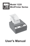
Model 122X
MiniPrinter Series
User's Manual
CAUTION
Risk of electrical shock. Do not remove cover. No user serviceable
parts inside. Refer servicing to qualified service personnel.
Weigh-Tronix reserves the right to change
specifications at any time.
10/01 122XUser’sManual.p65 PN 7424-14954G
TABLE OF CONTENTS
Introduction ......................................................................... 1
Installation .......................................................................... 1
Installing the Paper ................................................ 1
To Remove the Paper Roll ...................................... 4
Operation ............................................................................ 5
Connecting and Powering up Your Printer .............. 5
Maintenance ....................................................................... 5
Changing the Printer Ribbon .................................. 6
Inserting a Ribbon with Paper in the Printer .......... 7
Printer Test and Setup ......................................................... 8
Printer Test ............................................................ 8
Accessing the Setup Menu ................................... 9
CONFIGURE ........................................................... 9
CUSTOM .............................................................. 12
SET CLOCK... ....................................................... 14
RESET SEQ# ....................................................... 15
Communication ................................................................. 16
Model 1220 RS-232 Serial Version ...................... 16
Model 1221 Parallel Version ................................ 18
Model 1222 Serial TTL Version ............................ 20
Model 1223 20 mA Current Loop Version ............ 21
Model 1224 RS-485 Serial Version ...................... 22
Control Codes ...................................................... 24
Default Table ..................................................................... 33
Specifications
Interface
Interface--Serial
Interface
-P
arallel
Interface-P
-Parallel
Character Buffering
Print Method
Character Matrix
Available baud rates:
300, 600, 1200, 2400, 4800, 9600, 19200
Voltage levels:
RS-232C: -9 Volts to + 9 Volts
TTL: 0 Volts to + 5 Volts
20mA current loop
RS-485: 200mV differential
Character format:
Standard ASCII character set—10 or 11 bits per
character, 7 or 8 data bits.
Even or odd parity selection for 7 data bits.
Bit mapped graphics—10 bits per character
required
Busy signal - Clear to Send (CTS) or XON-XOFF
36-pin Centronics
1.5K standard
8K optional
Approximately 9500 byte capacity with option installed.
Impact dot matrix
5 x 8 or 5 x 5
Character Spacing
24 column:
32 column:
40 column:
Line Feed Spacing
7.6 lines per inch, character mode
9.1 lines per inch, graphic mode
12.8 characters/inch
17 characters/inch
21 characters/inch
Print Speed 38 lines per minute for 24 column
33 lines per minute for 32 and 40 column
Paper
Table top:
Panel mount:
Power
1 Watts (idle), 10 Watts (while printing)
2.25"W x 2.75"D; 0.44" I.D.
2.25"W x 1.25"D
AC VVoltage
oltage 9 VAC (120 VAC stepdown converter included)
Multi-national converters optional
DC VVoltage
oltage
External Dimensions
Operating TTemp.
emp.
Optional 9-12 VDC
100mA idle, 1500mA with 100% printing, 2.9A peak with
100% printing
4.1"W x 4.5"L x 2"H
5°C to 40°C, 41°F to 104°F
Print Head Life
Ribbon life
Paper
500,000 lines mean character before failure.
Black- 200,000 characters
Purple-250,000 characters
Large roll - 12,500 lines
Small roll - 3,000 lines
Introduction
The Model 122X impact printer series consists of these
models and electronic interfaces:
Model 1220 - RS-232
Model 1221 - Parallel
Model 1222 - TTL
Model 1223 - Current Loop
Model 1224 - RS-485
This manual is split into the following main sections:
•
Introduction
•
Installation
•
Operation
•
Maintenance
•
Printer Test and Setup
•
Communication
•
Default Settings
Installation
Follow the precautions listed below when setting up your
printer. They are designed to help you keep your printer
working at its best.
- Plug your power supply into an appropriate grounded
outlet.
- Place your printer on a flat hard surface, like a tabletop.
- Keep your printer out of direct sunlight.
Installing the PPaper
aper
1
1.
Remove the printer cover by pressing on the
groove patterns to pop the front edge up. Lift off
the cover.
2.
Press the rocker switch to the left. The light will
go off.
3.
Unroll several inches of the paper.
4.
Cut a straight edge on the paper roll if it is jagged.
This will facilitate the entry of the paper into the
printer.
5.
Slide the paper through the slot connecting the paper
compartment and the printer compartment. You can
slide it in about one-quarter inch before it stops.
6.
While holding the paper in place, press the rocker
switch to the Paper Feed position. The printer will
activate, and a rubber roller will pull the paper into the
printer compartment. Hold the switch in the Paper
Feed position until the paper emerges from the top of
the printer mechanism.
7.
When an inch of paper has emerged from the top of
the printer, release the Paper Feed button.
8.
Now pull the paper through the printer, until several
inches are exposed.
9.
Slide the paper through the slot in the printer cover.
2
10. Push the back of the printer cover down and into
place.
11. Press the front of the printer cover down to lock in
place.
12. Put the paper spindle into the paper roll as shown
below, and place the roll with the spindle onto the
snaps near the back of the printer. Turn the paper roll
to take up any slack in the paper feeding to the
printer. Make sure the roll of paper turns freely. If it
does not turn freely, the paper will jam and will
possibly damage the printer mechanism.
3
To Remove the PPaper
aper
Roll
1.
Advance the paper about one inch beyond the paper
cutter by using the Paper Feed switch.
2.
Lift the paper roll away from the printer housing and
cut the paper feeding to the printer with scissors. Try
to make the cut as square as possible to help the next
time you reload the paper.
3.
Pull the remaining paper through the printer mechanism. Be sure to pull the paper from the top
(paper cutter side).
WARNING! Pulling the paper out of the back
of the printer will damage the print mechanism.
4
Operation
Connecting and
Powering Up
Your PPrinter
rinter
For DC modified
units supplied with
cable, connect
positive voltage to
striped wire.
1.
Attach the appropriate cable between the printer and
your host device. The connector on the printer side is
“keyed” so that you cannot plug the cable in the
wrong way. This means that the pins should be
positioned so that a slight pressure will seat the cable
properly. Do not force the pins in. Doing so could
damage the cable.
2.
Plug the power cord into the back of the printer. Plug
the transformer into an appropriate AC outlet. The
unit will power up automatically and print Ready
eady. This
means the printer is ready to print.
The Paper Feed switch on the printer is a rocker type
switch. Push the left side of the rocker switch to toggle
the printer on and offline. Push the right side of the switch
to advance the paper.
Your printer is now ready for printing.
The printer stores characters for printing until one of two
things happens:
1.
Its line buffer is filled.
2.
It receives a line feed (hexadecimal 0A) or a carriage
return (hexadecimal 0D) code.
When (1) or (2) occurs, the printer prints out the contents
of its line buffer. If the buffer is empty when the carriage
return is received, the printer simply advances the paper
one line, leaving a blank line in the printout.
Maintenance
When printing becomes faint or difficult to see, replace
the ribbon in your printer with an NCI cartridge ribbon.
Ribbon Type:
Black
Purple
Long-lasting Black
5
NCI Part Number:
223320029
223320011
223320045
Changing the PPrinter
rinter
Ribbon
If your printer is used infrequently, the print impression
may become weak because the ribbon has dried out. To
advance the ribbon to a new section, hold down the
Paper Feed switch for several seconds.
Below are the steps for replacing the ribbon:
1.
Turn the printer offline.
2.
Four small grooves are embossed on each side of
the printer cover. Push down on one or both of these
areas until the printer cover tilts.
3.
When the printer cover is tilted up, lift it completely
off.
4.
Push down on the right side of ribbon cartridge
where it is marked “PUSH”. Remove the cartridge.
6
If you get ribbon
ink on the printer
case, wipe it off
immediately.
Once it dries it is
difficult to
remove.
5.
Install new cartridge. Be sure the ink cartridge is
inserted firmly to prevent weak or irregular printing.
The cartridge must be properly seated and aligned
for best printing.
6.
Turn the cartridge “knob” (marked by an arrow)
clockwise to stretch the ribbon.
7.
Replace the cover.
8.
Replace the paper.
You may insert the ribbon cartridge if there is already
paper in the printer.
Hold the cartridge as shown above and slide it over the
paper and into the printer compartment. Be sure the
paper goes between the ribbon cartridge and the ink
ribbon.
7
Printer Test and Setup
The printer can be tested and setup using the steps
described in this section. Testing and setup are done
using the rocker switch on the printer.
Printer TTest
est
With the printer unplugged at the outlet or at the back of
the printer, press and hold the right side of switch as you
plug the unit in. The printer will print out a list of the
configuration as it currently exists then do a continuous
print test. To stop the print test, press either side of the
rocker switch. Below is a sample of what is printed when
you do the print test.
T & D will be
printed in the list to
the right if the
Time and Date
option is installed.
8
Accessing the Setup
Menu
This manual
assumes the time
and date option is
installed and
operating. If you
do not have this
option you will not
see references to
the clock or date
listed in most
menus.
To access the setup menu follow these steps:
1.
Unplug the printer either at the outlet or at the back of
the printer.
2.
Press and hold down the left side of the rocker switch
and plug in the printer. The printer will advance the
paper. After the paper advance has stopped, count for
3 to 5 seconds and then release the switch. The
following is printed:
If you wait less than three or more than five seconds
Ready is printed and you will have to try steps 1 and 2
again to access the setup menu.
After you access the setup menu, if you press NEXT (left
side of switch) repeatedly you will see the following list
printed. If you keep pressing NEXT (left side) the list
repeats itself.
As you can see from the above printout the setup menu
contains the following items:
CONFIGURE menu
•
CUST
OM menu
•
CUSTOM
OCK menu
SET CL
•
CLOCK
RESET SEQ#
•
The following pages explain these items and how to
customize the printer to your needs.
CONFIGURE The first setup menu item reads
CONFIGURE
9
[NEXT/OK]
[NEXT/OK] is a visual clue so you know that pressing the
left side of the rocker switch will go to the NEXT part of
the menu and that pressing the right side of the rocker
switch will accept (or say OK to) what this line of the setup
menu says.
With the printer in the setup menu and with
CONFIGURE [NEXT/OK] as the last item printed, press
OK (right side) to access the CONFIGURE menu. The
following is printed:
Load Defaults
LOAD DEF
AUL
TS gives you the opportunity to reset the
DEFAUL
AULTS
printer to all default settings (shown below).
* The parallel
interface does not
have these
selections.
Choose OK to do this or NEXT to go to the next parameter. The following is printed:
The complete list
of defaults is
shown in the
Default Table at the
end of this manual.
Baud Rate
Baud rate is the next parameter you can set in the
CONFIGURE menu. The complete list of parameters and
their possible values is shown below.
The sample list above shows the current baud rate is
1200. To accept this, press OK (right side) or view the
next baud rate value by pressing NEXT (left side). Press
OK when the baud rate you want is displayed.
Choose from these baud rates;
300, 600, 1200, 2400, 4800, 9600, or 19200
Data Bits
DATA BITS is the next parameter. Choose the data bit
value the same way baud rate was chosen. Choices are 7
or 8 data bits.
10
Parity
Stop Bits
Handshak
Handshakee
Handshake is
used for serial
interface only.
Parity can be selected only if 7 data bits are set. Choose
Odd or Even. If you choose 8 data bits, parity defaults to
None.
ST
OP BITS is the next parameter. Choose 1 or 2 stop bits.
STOP
1 stop bit is used for 10 bit words, 2 stop bits are used for
11 bit words.
HANDSHAKE is the next parameter. Choose from the
following settings:
BUSY-LINE
BUSY-BUFFER
XON/XOFF-LINE
XON/XOFF-BUFFER
NONE
Columns
COL
UMNS is the next parameter. Select the number of
COLUMNS
characters per line (columns) for this parameter. The
choices you have are 24, 32, or 40. Below are samples of
each:
Invert
INVERT is the next parameter. Choose OK if you want
inverted text (upside down) or NEXT if you want noninverted text (right side up) in your printouts. Below is an
example of inverted text.
Font
Magnification
FONT is the next parameter. Choose from a 5 x 5 dot
matrix print pattern or a 5 x 8 dot matrix pattern. The
5 x 5 dot pattern produces only upper case (capital)
letters.
The last parameter is MAGNIFICA
MAGNIFICATION
TION. This refers to the
TION
size of printed type from your printer. Your choices (with
examples) are
NONE
DOUBLE WIDE
11
DOUBLE HIGH
DOUBLE WIDE/HIGH
After you choose one of the magnifications the printer will
print Ready to show the printer is out of the configuration
menu and the setup menu and is ready to print.
CUST
OM
CUSTOM
The next setup menu item after CONFIGURE is
CUSTOM
OM. With the printer in the setup menu and with
CUST
OM
CUST
OM as the last item printed, if you press OK (right
CUSTOM
side) the printer will print the following:
If you press OK the printer will print the current custom
setup. A sample is shown below.
This printout shows you how each item is currently set.
Below is an explanation of each item and the choices you
can make for each.
12
T/D Format
This feature is
available only on
units with the
time/date option
installed.
Time/date option
is Y2K compatible.
Auto T&D
Appears only if the
clock is installed.
MM/DD/YY hh:mm ?M
MM/DD/YY hh:mm ?M DOW
MM/DD/YY hh:mm
MM/DD/YY hh:mm DOW
DD-MM-YY hh:mm ?M
DD-MM-YY hh:mm ?M DOW
DD-MM-YY hh:mm
DD-MM-YY hh:mm DOW
DD-MON-YY hh:mm ?M
DD-MON-YY hh:mm ?M DOW
DD-MON-YY hh:mm
DD-MON-YY hh:mm DOW
NONE
MM = month
DD = day
YY = year
hh = hour
mm = minutes
?M = AM or PM
DOW=Day of week
AUT
O TIME AND D
ATE is the next parameter.
AUTO
DA
Your choices are:
YES autoprint after CR (carriage return)
NO do not autoprint after CR
Autoprint of the time and date will not occur unless three
seconds has elapsed since the printer has stopped
printing.
Auto Seq#
AUT
O SEQUENCE NUMBER is the next parameter.
AUTO
Choices:
YES autoprint sequence number after CR
NO don’t autoprint sequence number after
CR
Autoprint of the sequence number will not occur unless
three seconds has elapsed since the printer has stopped
printing.
Zero
ZERO is the next parameter. Choose how you want the
zero character to look in your printouts. Choose between
0 and Ø.
Pound Sign
_Underscore
Busy Invert
13
TIME/D
ATE FORMA
TIME/DA
FORMATT is the next parameter. Choose from
the following formats.
POUND SIGN is the next parameter. Choose to show
pound as # or as the British sterling pound symbol £.
_UNDERSCORE is the next parameter. Choose which
_)
symbol the same ASCII code will print, an underscore (_
or a left arrow (➔).
BUSY INVERT is next. This controls the logic level for a
busy signal for the CTS line.
Choices:
YES NO -
voltage will be in a low state until the
unit is busy then voltage level goes high.
voltage will be in a high state until the
unit is busy then voltage level goes low.
Online/Offline
ONLINE/OFFLINE is next.
Choices:
YES enables the rocker switch to turn the
printer offline.
NO disables the ONLINE/OFFLINE ability.
Ext Ch Set
EXT CH SET is next. This stands for Extended Character
Set.
The choice to use
the extended
character set is
available only
when 8 data bits
are chosen.
Print Ready
Choices:
YES NO -
Allows you to use hexidecimal numbers
above 80 (true only for 8 data bits.)
Disables the Extended Character Set
ability.
PRINT READ
Y is next.
READY
Choices:
YES NO -
Prints Ready upon power up.
Disables printing Ready
WARNING - If you choose NO
NO, then you will need to
hold the left side of the rocker switch down for 4 to 6
seconds to access the setup menu. Begin timing when
you plug in power to the unit and the red light comes
on. The paper feed motor does not run upon power up
when Ready is disabled.
SET CL
OCK
CLOCK
OCK
The next item in the Setup Menu is SET CL
CLOCK
OCK as
With the printer in the setup menu and with SET CL
CLOCK
the last item printed, if you press OK (right side) the printer
will print the following:
The printout shows the year currently in memory. The 0 is
reversed (white on black) to show the position of the
cursor. This is the number which will be incremented if
NEXT (left side) is pressed. If the number is correct press
OK (right side) and the following is printed:
14
This feature is
available only on
units with the
time/date option
installed.
DOW :
0=Sunday
1=Monday
2=Tuesday
3=Wednesday
4=Thursday
5=Friday
6=Saturday
The cursor now appears over the 2nd position. Press
NEXT (left side) to increment this number if needed and
OK if it is right. Continue this sequence of accepting or
changing the year, month, day, and DOW (Day Of Week).
ATE menu the
When you have completed the SET D
DA
following is printed automatically:
Choose NEXT (left side) to increment the number or OK
(right side) to accept the 1. Repeat this same procedure
for hours and minutes as shown below.
When everything is as you want it and you press OK
OK,
ART CL
OCK is printed. Press OK (right side) to start the
START
CLOCK
ST
clock. The printer then prints Ready showing you that it is
out of the setup menu and ready to print.
RESET SEQ#
15
RESET SEQ# is the last setup menu item. This menu item
lets you reset the sequence number. This number is the
number of print transactions since the last reset.
With the printer in the setup menu and with RESET SEQ#
as the last item printed, if you press OK (right side) the
sequence number will be reset to zero and the printer will
print Ready and printer is ready to print.
To skip resetting the sequence number to zero, press
NEXT (left side). CONFIGURE is printed. Unplug and replug
in the printer to return to printing mode. Ready is printed.
Communication
This section shows the cable differences in the models
of the 1220 series printer and the control codes and
communication protocols.
Model 1220
RS
-232 Serial VVersion
ersion
RS-232
Pin No.
Signal
DTE Direction
Description
1
Chassis ground
-
Cable shield
2
(TD) Transmitted
From printer
Printer data output line
data
3
(RD) Received data
To printer
Printer data input line
7
(SG) Signal
-
Signal ground
11
(CTS) Clear to send
From printer
Signal (equivalent to
BUSY) indicating that
printer is ready for
operation and can
receive data.
The rest are not used.
16
Model 1220 (2600)
-232 Serial VVersion
ersion
RS-232
RS
Pin No.
Signal
DTE Direction
Description
1
Chassis ground
_
Cable shield
2
(RD) Received data
To printer
Printer data input line
5
(CTS) Clear to send
From printer
Signal (equivalent to
BUSY) indicating that
printer is ready for
operation and can
receive data.
7
(SG) Signal
_
Signal Ground
The rest are not used.
Serial Interface V
oltage L
evels
Voltage
Levels
Received data:
Mark = OFF = Logic “1” = -25V to -3V
Space = ON = Logic “0” = +25V to +3V
Clear to send:
Busy = OFF = Logic “1” = -9V
Not Busy = ON = Logic “0” = +9V
Transmitted data:
Mark = OFF = Logic “1” = -9V
Space = ON = Logic “0” = +9V
17
Model 1221
Parallel VVersion
ersion
Pin No.
1
Signal
Direction
Data Strobe
To printer
Description
Samples input data when held low for
10 microseconds.
2
Data Bit 1
3
Data Bit 2
4
Data Bit 3
5
Data Bit 4
6
Data Bit 5
7
Data Bit 6
8
Data Bit 7
9
Data Bit 8
10
Acknowledge
Indicates input data.
To printer
High level indicates “1” and
low level “0”.
From printer
Indicates character input completion
at low level.
11
BUSY
From printer
Indicates data cannot be received at
high level.
16-29
0 Volts
-
Twisted pair return (For pins 1 to 11)
12
0 Volts
From printer
High = Out of paper.
13
+5v
From printer
High = printer selected.
32
+5v
From printer
Low level = Error condition.
The rest are not used.
18
1.
2.
3.
Connectors
On the printer: 36-pin receptacle, equivalent to
57-40360-12-D56 AMP
On the cable: 36-pin plug, equivalent to 57-30360
AMP or plug equivalent to 552274-1 AMP
cover equivalent to 552073-1 AMP
Cable
Use a cable less than 10 feet long. A shielded cable
using twisted pair conductions is desirable.
Connector Locks
After engaging the connectors, fasten them with
locks.
T1 = 0 minimum
T2 = 0.5 microseconds minimum
T3 = 1 microsecond minimum
T4 = Approx. 6.8 microseconds
19
Model 1222
Serial TTL VVersion
ersion
Pin No.
Type
1
2
3
4
5
BUSY
GROUND
RCV. DATA
XMT DATA
NOT USED
20
Model 1223
20 mA Current Loop
Version
Pin No.
Signal
Direction
Description
1*
Chassis ground
-
Cable shield
23
(RD) Received data(-)
From printer
Printer data return line
25
(RD) Received data(+)
To printer
Printer data input line
*Optional
The rest are not used.
21
Model 1224
RS
-485 Serial VVersion
ersion
RS-485
Pin No.
Signal
DTE Direction
Description
2
TXD -
From printer
Printer data output line
6
TXD +
3
RXD -
To printer
Printer data input line
8
RXD +
The rest are not used.
22
1.
2.
23
Connectors
On the printer: 25-hole receptacle, equivalent to
DB-25S
On the cable: 25-pin plug, equivalent to DB-25P
Cable
Use cable less than 2500 feet long
long.. A shielded cable
using twisted pair conductors is desirable.
CONTROL
CODES
According to the American Standard Code of Information
Interchange (ASCII), there are 32 control codes in addition
to the codes for the printable characters. (Control codes
are sent as data, but the receiving device interprets them
as abbreviated ‘’instructions”, communication - status
messages, etc.)
The printer recognizes these control codes:
Function
Reserved
Reserved
Reserved
Back Space
Line Feed
Carriage Return
Double Height
Double Width
Reset Seq. # to 0000
Inhibit Line Space
Dot Graphics
User Character
Set Time & Date
Reserved
Get time and date
Stop Reverse Field
Reverse Field
Escape
24 Column Mode
32 Column Mode
40 Column Mode
Abbreviation
Hex
NUL
SOH
STX
ETX
EOT
ENQ
ACK
BEL
BS
HT
LF
VT
FF
CR
SO
SI
DLE
DC1
DC2
DC3
DC4
NAK
SYN
ETB
CAN
EM
ESC
FS
GS
RS
US
00
01
02
03
04
05
06
07
08
09
0A
0B
0C
0D
0E
0F
10
11
12
13
14
15
16
17
18
19
1B
1C
1D
1E
1F
Code
Decimal
0
1
2
3
4
5
6
7
8
9
10
11
12
13
14
15
16
17
18
19
20
21
22
23
24
25
27
28
29
30
31
The printer will ignore all other control codes.
24
Back Space
Code 8
Line Feed
Code 10
25
Upon receipt of this code, the printer erases from its
buffer the previously received character. This is useful in
correcting typing errors for programs that send data both
to a video screen and the hardcopy printer. Remember
that if you type more characters than the printer can print
on a line, the printer will automatically start printing.
The printer handles this control code in exactly the same
manner as carriage return (control code 13) except when a
line feed immediately follows a carriage return. The line
feed code is ignored if it is immediately preceded by a
carriage return. The default setting is 7.6 lines per inch.
Carriage Return
Code 13
Whenever a carriage return code is received, the printer
will print out the current contents of its buffer, then clear
the buffer to get ready for additional data.
Double Height
Code 14
This control code tells the printer to switch to the double
height character line. The control code can be sent at any
time on a line; it need not be the first code received by the
printer after a carriage return.
You cannot mix normal and double height characters on
the same line. Once you select the double height, the
printer will remain in that mode until it receives a carriage
return or line feed. A line print caused by a buffer full
condition will not clear the double height command. This
means that the “wrap around” print line will also be
double height if the double height command was sent
before the line buffer was filled.
Double Width
Code 15
This control code tells the printer to switch to double
width character printing. The control code should be sent
as the first character on a line. If it is received after half the
maximum characters per line were sent then the printer
will ignore all characters on the last half of the line.
You cannot mix normal and double width characters on
the same line. Once you select the double width, the
printer will remain in that mode until it receives a carriage
return or line feed. A line print caused by a buffer full
condition will not clear the double width command. This
means that the “wrap around” print line will also be
double width if the double width command was sent
before the line buffer was filled.
Enlarged PPrinting
rinting
Codes 14 and 15
Enlarged printing may be selected by sending both the
double height command (control code 14) and the double
width command (control code 15). The control codes may
be sent in either order, but because of the double width
restrictions, the codes should be sent at the beginning of
a line.
Example of Control Codes 14 and 15:
Reset Sequence
Number
Code 1166
Inhibit Line Spacing
Code 17
When the printer receives this control code it will immediately reset the sequence number to 00000.
A standard character line is made up of ten dot lines. Eight
of these dot lines are used for the printable character and
two are used for space between lines. When using
character graphics it is desirable to eliminate the two
blank lines so the graphic characters connect together.
Sending a CHR$(17) (control code 17) anywhere on a line
of data will stop the printer from putting space between
that line and the next. If a CHR$(17) is not on a print line,
the normal space between lines will be printed.
Example:
Run:
26
Dot Graphics
Code 18
The mechanism used in the printer prints one line of dots
across at a time. This means that when it prints one line
of characters it has actually printed ten lines of dots
where the first eight lines make up the character and the
last two lines are blank for the space between character
lines. By using the CHR$(18) control code, you can tell the
printer which dots to print for one whole dot line. Since
there are 144 dots per line, you must follow the CHR$(18)
control code with 144 bits of information. For every place
there is a one in the 144 bit pattern you send, the printer
will print a dot. Rather than receive one bit at a time the
printer expects to receive the information eight bits at a
time. This means that after receiving a CHR$(18) the next
eighteen 8 bit characters it receives will be printed as
dots to form one dot line.
To figure out the dot pattern values to send after the
CHR$(18), you will need some grid paper. A large sheet
with 144 grid boxes across would be convenient. If such a
large sheet of paper is not available, you could divide your
pattern in half and work with 72 grid boxes across. Divide
up your grid paper by drawing a heavy line down every 8
boxes across. Now fill in each box of the grid that you
want to be printed. Now do the following procedure to
compute the eighteen values which describe your desired
bit pattern.
Imagine placing the number sequence over each of the
first eight grid boxes.
Now add together all the numbers above the boxes which
are filled in or have a dot as in the example above. In our
example, we would have 2 + 16 + 32 which equals 50.
‘50’ then would be the first entry of a data statement
which would be followed by seventeen more numbers
computed in the exact same manner as the example.
Once you have the eighteen values in a data statement,
you need simply run a program which prints a CHR$(18)
followed by the data value read from the data statement.
Don’t forget to end all of your print statements with
semicolon. This will prevent carriage returns CHR$(13)
from being sent, which would become part of the
eighteen data values for which the printer is waiting.
27
Example 1:
Example 2:
User PProgrammable
rogrammable
Character
Code 19
By using CHR$(19) you enter the Custom Character mode.
This allows you to design and print your own 6 x 8 character by inputting data. A data statement is made of numbers that represent a row of dots which when read all
together, will make up your character. To design your
character, follow the example below. You should notice
that each number in the data statement corresponds to
one row in your character. To design a character, follow
these steps:
28
1.
Use quad ruled paper to design your character.
2.
Number 8 consecutive rows like this:
1
2
4
8
16
32
64
128
3.
Now design your character in dot form (see the
example below).
4.
Add together all the numbers from the column on the
left, counting only where you have placed a dot in a
row. In our example, the first column has three dots
located in rows 4, 8, and 16. Added together they
equal 28.
5.
Put your final total for each column into a data
statement in column order.
TOTAL
The data statement in your program will read:
DATA 28, 34, 65, 65, 54, 34
The next step is to tell the printer your newly designed
character. To do this you must send a CHR$(19) followed
by the six numbers you computed above. Following is an
example of how this can be done.
29
After typing RUN, your custom character will be stored in
the printer’s memory. It will retain this information until
the printer is switched off or until you write over the data
by defining a different character.
To print your newly designed character, simply send
CHR$(126) which corresponds to hexidecimal value 7E.
Set Time and Date
Control Code 20
This control code is used when setting the printer’s time
and date clock. Following is the text string to send when
setting the clock:
Read Time and Date
Control Code 22
This control code is used to read the printer’s time and
date clock. Following is the ASCII string received:
Cancel Reverse Field
Control Code 24
Sending this control code will turn off the reverse field
mode that is selected using control code 25.
Reverse Field Control
Code 25
Send this control code to turn on the reverse field
printing mode. This will print white letters on a dark
background. Do not print more that three reverse field
print lines. Also, do not print more than a few empty
spaces in a reverse field. The printer may become
overloaded and stop printing.
30
Selectable Column
Width
Codes 29, 30, 31
The printer powers up in the column mode last selected by
configuration. You can change the column width by
sending the appropriate control code from the list below:
Control code 29 - 24 columns
Control code 30 - 32 columns
Control code 31 - 40 columns
You can send the control code at any point on a line
before the buffer becomes filled. You cannot change
column widths on the same line.
Printable Characters
The Model 122X printer can produce all ASCII characters
from hex 20 through hex 7D (decimal 32 through 125).
Here’s what they look like:
Note the last two codes of the usual ASCII character set
are not supported. Instead, if CHR$(126), which corresponds to hexadecimal 7E, is received by the 122X printer,
it will print the character defined in its RAM (Random
Access Memory). The section on USER Programmable
Character describes how this RAM can be loaded with
any 6 x 8 pattern.
The model 122X also has a graphic character set that
resides between hexidecimal values 80 and FF (decimal
128 and 255). The symbols used are compatible with
Radio Shack® Model 100 portable computer.
31
For special applications please contact our Customer
Service Department for further assistance:
Phone
Fax
Printer Escape
Command Code
Definitions
Command
<ESC> 0
<ESC> 1
<ESC> 2
<ESC> 3
<ESC> 4
<ESC> 5
<ESC> 6
<ESC> 9
800-982-6622
707-527-5555
800-847-6743
707-579-0180
Print formatted data
HH:MM
24 hour format
HH:MM_?M 12 hour format with AM or PM
MM/DD/YY month/day/year
DD-MM-YY day-month-year/numeric month
DD-MON-YY day-month-year with 3 letter
abbreviation of the month
DOW
day of week abbreviation
currently configured format
XXXX
current sequence number
32
Default Table
Below is a table showing the possible values for the
Custom and Configuration menu parameters. The values
shown in bold type are the default settings.
Custom Menu
T/D Format
1 2 3 4 5 6 7 8 9 10 11 12 13 -
None
MM/DD/YY_hh:mm_?M
MM/DD/YY hh:mm ?M DOW
MM/DD/YY hh:mm
MM/DD/YY hh:mm DOW
DD-MM-YY hh:mm ?M
DD-MM-YY hh:mm ?M DOW
DD-MM-YY hh:mm
DD-MM-YY hh:mm DOW
DD-MON-YY hh:mm ?M
DD-MON-YY hh:mm ?M DOW
DD-MON-YY hh:mm
DD-MON-YY hh:mm DOW
Configuration Menu
Baud
1
2
3
4
5
6
7
-
300
600
1200
2400
4800
9600
19200
Data Bits
1 - 7
2 - 8
Parity
1 - ODD (none if data bits = 8)
2 - EVEN (none if data bits = 8)
Auto T&D
1 - NO (no print after CR)
2 - YES (print after CR)
Stop Bits
1 - 1
2 - 2
Auto SEQ#
1 - NO (no print after CR)
2 - YES (print after CR)
Handshake
1
2
3
4
5
-
None
BUSY-LINE
BUSY-BUFF
XON/XOFF-LINE
XON/XOFF-BUFF
(serial only)
(serial only)
(serial only)
(serial only)
Zero
1 - Ø Zero with slash
2 - 0 Zero without slash
Pound
1 - # U.S. pound symbol
2 - £ British pound sterling
Columns
1 - 24
2 - 32
3 - 40
Underscore
1 - _ Underscore
2 - ➔ Left arrow
Inver
1 - No (non-inverted printing)
2 - YES (inverted printing)
Busy Invert
1 - Non-inverted busy (CTS)
2 - Inverted busy
Font Type
1 - 5x8 font
2 - 5x5 font
symbol
Online/Offline 1 - switch function enabled
2 - switch function disabled
Ext Ch Set
1 - NO (no extended char. set)
2 - YES
Print Ready
1 - Print “Ready” message
2 - Don’t print “Ready” message
33
Magnification 1
2
3
4
-
No magnification
Double width
Double height
Double width, double height
Notes
1000 Armstrong Drive
Fairmont, MN 56031 USA
Telephone: 507-238-4461
Facsimile: 507-238-4195
E-mail: service @wt-nci.com
www.wt-nci.com