1
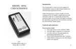
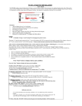
WARRANTY
All UFI instruments are warranted against defects in materials and workmanship to the original
using purchaser for a period of one year from the date of original purchase. The warranty is void
if our inspection shows the equipment has been tampered with, or installed at variance with
factory designated procedures or has been subjected to negligence, misuse, accident beyond
normal usage, or has had it's serial number altered, defaced, or removed.
All questions regarding the warranty stated above should be directed to:
CUSTOMER SERVICE DEPT.
UFI
545 Main Street Suite C2
Morro Bay, CA 93442
NO person, including any dealer or agent is authorized to assume any liability for UFI. When
corresponding or communicating with UFI concerning your equipment, please include the model
number and serial number of the instrument.
UFI instruments and transducers are subject to continuous improvement. We reserve the right to
modify any design or specification without notice and without incurring any obligation.
ALL UFI TRANSDUCERS AND ELECTRODES ARE COVERED BY OUR
EXCLUSIVE "LIFELINE® WARRANTY" AS OUTLINED BELOW
LIFELINE® WARRANTY
If your UFI transducer, electrode, or electrode tester ceases to operate---regardless of the cause--accidental, intentional, or whatever---RETURN IT TO US.
We will repair it or replace it with a new one for a minimal handling charge, as listed below:
Model 1010, 1010C, 1020, 1020EC, 1020FC, 1110-----------------------------------Model 1030, 1040, 1070, 1081FT--------------------------------------------------------Model 1081 & 1081 SNP------------------------------------------------------------------Model 1089 MK II & MK III-------------------------------------------------------------Model 1130, 1131, 1132-------------------------------------------------------------------Prices subject to change
$25.00
$50.00
$11.00
$65.00
$35.00
MODEL 1089 MK III NP CHECKTRODE®
(eff. 5/2007)
INTRODUCTION
The CHECKTRODE® Electrode Tester may be used to:
A. Test the integrity of electrode/skin contact in physiological and/or
bioelectrical data acquisition systems;
B. Test the integrity of associated electrode wires used in such systems;
C. Test the "quality" of the electrodes;
D. Test external batteries (9 V & others) such as used in telemetry and other
physiological monitoring systems.
1. FUNCTION OF CONTROLS AND CONNECTORS
POWER SWITCH
Push button — turns unit ON. Power remains ON for approximately 3 minutes then
AUTOMATICALLY TURNS OFF.
FUNCTION SELECTOR SWITCH
4 position switch which selects the measurement function of the CHECKTRODE®
50 KΩ TEST - Connects a precision 50 KΩ resistor to the CHECKTRODE® INPUT. The
instrument should read between 49.5 and 50.5.
IMPEDANCE (KΩ) - Displays the electrode contact impedance in KΩ (between 0 and 199.9
KΩ). The display will indicate "1" when the electrode impedance exceeds 199.9 KΩ
OFFSET (mV -) displays the potential generated by a pair of electrodes when connected to the
body. Known as "offset potential", this measurement indicates the purity of the metals used in the
electrode manufacturing process. The lower the reading the higher the purity. Readings which
vary wildly or which exceed "10" are usually indicative of severe electrode problems.
EXT BATTERY - Reads the voltage of a battery when it is connected to the EXTERNAL
BATTERY TEST CONNECTOR.
ELECTRODE SELECTOR SWITCH
When your electrode cap is connected to the connector on the back of the unit this switch allows
you to quickly test the contact impedance of the selected electrode on the cap against the linked
ear reference electrodes.
TEST SWITCH
The TEST switch allows you to test the linked ear reference electrodes against each other I order
to verify their proper connection to your subject, or to test each of the electrodes on the electrode
cap against the two linked ear reference electrodes together
REF – When the TEST switch is in this position you can test the reference
electrodes against each other. If the reference electrodes are separate from the connector which is
attached to the electrode cap then you will need to plug the connectors for the electrodes into the
connectors provided on the front panel. If the reference electrodes are incorporated into the DB25
connector provided on the electrode cap then you need do nothing extra. With the TEST switch
in this position you can also test any two electrodes attached to your subject using the connectors
on the front panel.
CAP – When the TEST switch is in this position the reference electrodes are now
linked and act as a single reference electrode. You can now test each electrode as selected by the
Electrode Selector Switch against the reference electrodes in order to assess its connection to your
subject.
2. USING THE CHECKTRODE®
CHECKING INTEGRITY OF ELECTRODE CONTACT
a) Prepare the electrode sites and attach the electrodes.
b) Connect the electrode cap to the mating connector on the back of the unit or insert the
electrode connectors for two individual electrodes into the mating connectors on the front
panel.
c) Depress the POWER SWITCH. Set the FUNCTION SWITCH to 50KΩ TEST. The
display should indicate between 49.5 and 50.5.
d) Set FUNCTION SWITCH to CONTACT (KΩ) —The display will indicate the integrity
of the electrode contact. Higher impedances are indicative of poor skin preparation, and
often result in a recording with moderate to severe motion artifacts.
5KΩ or below
Good prep
5KΩ — 10 KΩ
OK, but can cause some noise
10 KΩ — 30KΩ
FAIR, might improve with time,
but for best results, should be removed
and skin re-prepped.
30 KΩ & above
BAD, will cause much noise on the recording
with the slightest patient motion.
REMOVE AND RE-PREP!
e) If testing electrodes in your electrode cap, slowly switch through the available switch
positions to test each available electrode on your cap.
CHECKING INTEGRITY OF ELECTRODE WIRES
a) Connect one electrode wire to the RED ELECTRODE INPUT JACK.
b) Energize instrument as above. Select "CONTACT KΩ"
c) Connect the free ends of the wire the snap connector on the CHECKTRODE. The display
should read "00.0" and not change. If the display changes with wire motion, there
probably is an intermittent open in the wire.
CHECKING OFFSET POTENTIAL
a) Connect electrodes as in Section 1.
b) Select "OFFSET" with the FUNCTION SWITCH
c) The display will indicate the potential generated by the half-cell combination of two
electrodes and the body. The reading should be "10" or below.
BATTERY TEST
a) Select "EXT. BATTERY" with the FUNCTION SWITCH
b) Depress POWER button
c) Connect the battery to be tested to the BATTERY TEST CONNECTOR. The display will
indicate the battery voltage.