1
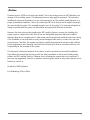
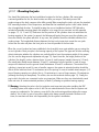
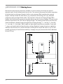
›English - Electronic Levelling System Assembly Manual 75 › Content Set content Preface Assembly in 10 steps 1 Mounting the jacks 2 Installing the pump Ordering hoses 3 Installing electronics 4 Laying the hydraulic hoses 5 Filling oil 6 Power connection batteries Control panel 7 Taking the system into operation 8 Programming zero point + air suspension mode (when installed) 9 New features panel 10 VB-EP-connection and compatibility 11 Finishing the installation 12 Maintenance of the system Page 76 Page 77 Five brief tips for the customer Cylinders & technical data Adapters & clamps The error mode Page 88 Page 89 Page 90 Page 94 Page 78 Page 79 Page 80 Page 81 Page 82 Page 82 Page 82 Page 83 Page 84 Page 85 Page 86 Page 87 Page 88 Page 88 › Set content 1pump 2 four cylinders 3 control panel 4 main unit 5 three electric cables: a) cable with 9-pole plug b) cable with 4-pole plug c) cable with 6-pole plug 76 6 power fuse incl. holder for battery 7 connecting nipples for inside the cylinders (8 stops/10 nipples/1 T-piece) 8 end user manual 9 order form for the hydraulic hoses › Preface Products must be 100% user friendly and reliable. That is the strategic vision at E&P Hydraulics, the designer of this levelling system. This philosophy does not only apply to customers. The mechanics installing the system at the dealers, are also very important to us. Our product greatly depends on a proper, professional installation. That is the reason why E&P do all they can do to support the people who must install the system. This assembly manual is part of this policy. In 10 steps we will explain as simply as possible how this system can be installed as properly and efficiently as possible. However, this does not mean that installing the E&P Levelling System is an easy job. Installing this system requires a high level of skill. After all, we are dealing with equipment that must be able to withstand huge forces, something that is often underrated by people with insufficient technical training. If the installation is not performed correctly, serious damages could result in a short time, and even personal injury. Therefore, this system may only be installed by professional mechanics with sufficient practical experience and a thorough relevant technical training. At all times, mechanics will bear sole responsibility for the assembly of the system. This document is based on hundreds of test hours as well as hundreds of successful installations. If you follow this manual step-by-step, you will see what a wonderful as well as user friendly quality product the E&P Levelling System is. However, there will always be aspects that can be improved. If you have any suggestions, remarks or questions concerning this manual or the product, please do not hesitate to contact us. On behalf of E&P Hydraulics Eric Klinkenberg & Pierre Blom 77 › STEP 1 Mounting the jacks You should first determine the best installation locations for the four cylinders. We cannot give a univocal guideline for this, the best location can differ per camper. Particularly around the undercarriage at the back, campers often differ greatly. When mounting the jacks, only use the standard E&P mounting brackets. Out of experience, we know that the installation space is ofter rather limited, also in longitudinal direction. To simplify locating the correct installation location, E&P Hydraulics included all possible mounting plates and adapters in its range (for an overview, see the appendix on pages 13, 14, 15 and 16). Make sure that the position of the cylinders does not undermine the bearing capacity of the system. In general, the following will apply: the more apart the cylinders are, the more efficient the system will work. In any case, the cylinders should be installed outside of the undercarriage. The longitudinal distance between the legs is also important: mount the rear jacks behind the rear axle and place the front jacks as close as possible to the front axle. When the correct location has been established, check carefully once again whether you are using the correct cylinders. Basic principle is the bearing capacity of the system. Use type and all other ordering data to determine whether the cylinders are perfectly able to bear the maximum weight of the camper (for this, see the diagram and explanation on page 13). Apart from this, the height position of the cylinders (the length) is also a decisive factor. In case of small campers (weight class up to 5.2 tons), the raised jacks should remain between 18 and 21 centimetres from the ground; in case of larger campers the distance from the ground should be between 20 and 23 centimetres. The stroke of the cylinders is important as well. In case of smaller campers, the system in extended position should be able to lift the vehicle at least 12 centimetres out of the springs. In case of medium sized campers (3.5 tons of bearing capacity per cylinder) this is 14 centimetres, in case of large campers 18 centimetres (although there may be exceptions). For all this, also see the technical data on page 13). Finally, the way in which the jacks are connected is also very important. Make sure they are attached with sound bolts and nuts, at various extended positions (at least 6), allowing an optimum bearing capacity. !!Warning: Attaching the jacks is the first and also most important step when installing the E&P Levelling System, and requires a lot of skill. Do not underestimate the forces that the system and camper are subjected to. For instance, never drill in the undercarriage without asking the camper dealer if this is safe. In case of any other doubts, also always consult the dealer. Because at all times, the mechanic will bear sole responsibility for the system’s installation. 78 › SCHRITT 2 Montage der Pumpe STEP 2 Installing the pump SCHRITT 2 tosoMontage der Pumpe ForFür pumps subjected weather influences, the warranty will become invalid.ungeschützt For that reason, E&P Pumpen, die montiert wurden, dass sie Wind und Wetter ausgesetzt sind, erlischt die Garantie. Daher hat E&P einento speziellen Unterbauschutz Hydraulics developed a special subconstruction trayHydraulics (see photo next this paragraph) allowing you (siehe Fotounder rechts), mit demMost es möglich dieinside Pumpe außen unter to entwickelt hang the pump outside, the camper. pumps arewird, placed the camper in onedem of the Reisemobil zu befestigen. In den meisten storage spaces, at a location where it is easy Für SCHRITT Pumpen, die so montiert wurden, dass siePumpe Wind und Wetter ungeschützt ausgesetzt 2 Montage der Fällen wird die Pumpe im the Stauraum des lead pipes andGarantie. wires through camper’s sind,toerlischt die Daher hat E&P Hydraulics einen speziellen Unterbauschutz Reisemobils untergebracht, vonThe wo aus floor. Very(siehe often, Foto the main unit ismit also entwickelt rechts), demspecial es möglich wird, die Pumpe außen unter dem Leitungen und Kabel einfach über den subconstruction unit, incl bracket and plastic Reisemobil zu befestigen. In den meisten Für Pumpen, die so montiert wurden, dass sie Wind und Wetter ungeschützt ausgesetzt Boden des Reisemobils geführt werprotective housing mounted inDaher the same spaceHydraulics einen speziellen Unterbauschutz Fällen wird die Pumpe im Stauraum des sind, erlischt die Garantie. hat E&P denstep können. wirdbe ima selben Raum (see 3b), soOft itFoto would good entwickelt (siehe rechts), mit dem möglich wird, die Pumpe außen unter dem Reisemobils untergebracht, von woidea austoesleave auch die Zentraleinheit (Schaltkasten) enough space forbefestigen. thiseinfach purpose. Reisemobil zu Inüber den meisten Leitungen und Kabel den aufgehängt (siehe Schritt 3b), daher wäre Fällen wird die Pumpegeführt im Stauraum des Boden weresdes gut,Reisemobils wenn auch dafür noch genügend Reisemobils untergebracht, von wo aus !!Caution: to prevent failures, the pump den können. wird im selben Raum should Platz ist.Oft Leitungen und Kabel The einfach über be in a flat position. bottom of den the plastic auch die Zentraleinheit (Schaltkasten) Boden des Reisemobils geführt wer oil tank should be covered over its complete aufgehängt (siehe Schritt 3b), zu daher wäre Achtung: Um Störungen vermeiden können. Oft wird im selben Raum den, surface. Attach the pump using two M10 bolts. Die spezielle Unterbaueinheit, es gut, wenn auch dafür noch genügend De speciale onderbouwunit, incl. beugel muss die Pumpe gerade aufgestellt einschl. auch die Zentraleinheit (Schaltkasten) ist. When installing you should also take the pump’s Bügel und Plastikschutzabdeckung en plastic beschermingsbak Platz werden. Außerdem muss Boden aufgehängt (siehe Schritt 3b),der daher wäre gut, relayPlastiköltanks into account. aufnoch der gesamten esdes wenn auch dafür genügend Achtung: Um Störungen zuDie vermeiOber äche stabil sein. Befestigung der Pumpe erfolgt mit zwei M10-Schrauben. Beim Platz ist. will continuously have 12 volts running it, and we recommend protecting this fragile piece of Anbauthrough mussDie außerdem dasUnterbaueinheit, Pumpen-Relais beachtet werden. den,Itmuss die Pumpe gerade aufgestellt spezielle einschl. the pump with the supplied protective cap. At least make sure that the customer cannot place or throw Achtung: Um Störungen zu vermeiAuf diesem liegt immer eine Spannung von 12 Volt und es werden. Außerdem muss der Boden Bügel und Plastikschutzabdeckung anything ondie topPumpe ofauf it. Warning: when the Die pump, always take the emergency control into account muss gerade aufgestellt spezielle Unterbaueinheit, einschl. istplacing empfehlenswert, die emp ndlichen Teile der Pumpe mit des den, Plastiköltanks der gesamten werden. Außerdem muss der Boden Bügel und Plastikschutzabdeckung (a screw drill, for instance, should always be able to reach the front side of the electric motor). der mitgelieferten Kappe abzudecken und in jedem Fall dafür Oberäche stabil sein. Die Befestigung der Pumpe erfolgt mit zwei M10-Schrauben. Beim des Plastiköltanks auf der gesamten zu sorgen, dass der Benutzer nichts darauf legen oder werfen Anbau muss außerdem das Pumpen-Relais beachtet werden. Oberäche stabil sein. Die Befestigung der PumpeAchten erfolgt mitbeim zwei Anbringen M10-Schrauben. Beim Warnung: Auf kann. diesem liegt immer eineSie Spannung von 12 der VoltPumpe und esimAnbau muss außerdem das Pumpen-Relais beachtet werden. mer auf die Notbedienung istAuf empfehlenswert, die eine emp ndlichenvon Teile der Pumpe diesem liegtdie immer Spannung 12 Volt und es mit (u. a. muss Oberseite der Kappe abzudecken undder in jedem Fall ist mitgelieferten empfehlenswert, die emp ndlichen Teile Pumpe mit dafür des Elektromotors mit nichts darauf legen oder zudersorgen, dass derKappe Benutzer werfen mitgelieferten abzudecken und in jedem Fall dafür einem Akkuschrauber kann. Warnung: Achten Sie nichts beim Anbringen zu sorgen, dass der Benutzer darauf legender oderPumpe werfenimerreichbar sein. mer aufWarnung: die Notbedienung kann. Achten Sie beim Anbringen der Pumpe immer diedie Notbedienung (u. a. auf muss Oberseite (u. Elektromotors a. muss die Oberseite des mit t Die Notbedienung des Elektromotors mit einem Akkuschrauber Pumpe muss bei einem der Akkuschrauber erreichbar der sein. Montage beachtet erreichbar sein. werden. u ttDie DieNotbedienung Notbedienung der Pumpe mussbei bei Always the emergency control dertake Pumpe muss ofder the into account when Montage beachtet derpump Montage beachtet installing. werden. u werden. u 7 79 7 › INTERMEDIATE STEP Ordering hoses Now that the jacks and pump have been installed, it is time to measure and order the required hydraulic hoses. Use the included order form for this. The returns to the pump (the bottom connections u Zwischenschritt at the foot plate) can be looped through, but this is not necessary. When measuring the required lengths, seriously consider the heat sources (e.g. the exhaust) and moving parts (e.g. laminated suspension springs and hand brake cable). This could be a reason for not looping through. When Nachdem die Zylinder montiert wurden, können die benötigten Hydraulikschläuche finished, the hoses should be properly concealed, without any risk of wear or leakage. 10 hoses in total abgemessen und bestellt werden. Verwenden Sie dazu das beigelegte Bestellformular. Die will have to be made zur to size (8 in (die caseunteren of looping through). am TheZylinder) drawing atkönnen the backparallel of the order form Rückleitungen Pumpe Anschlüsse angeschlosshows the difference between looping through and not looping through (1 = rear left, 2 = front left, sen werden, dies ist aber nicht notwendig. Achten Sie beim Abmessen der der Schläuche 3 = auf rearmögliche right, 4 =Hitzequellen front right). Both straight and right-angled are possible. If you need (beispielsweise der Auspuff)connections und bewegliche Teile (beispielsT- pieces, should clearly this whenDies ordering. Nipples for sein, looping are supplied as weiseyou Federungen undindicate Handbremse). können Gründe diethrough Schläuche nicht parallel standard. Send the form us, and wemüssen will make sureder that you will receive the order a.s.a.p. Itgeschützt is also anzuschließen. DietoSchläuche nach Montage gegen Beschädigungen werden (z.B. Insgesamt müssen 10 Schläuche nach Maßmust eingebaut (8 bei possible, by the way,Leerrohr). to have the hoses made by a company near you (hose be ablewerden to withstand Parallelanschluß). at least 220 bar). Die Zeichnung der Schlauchanordnung auf dem Bestellformular zeigt die Unterschiede zwischen Parallelanschluß und Einzelanschluß (Rücklauf) (1= links hinten, 2 = links vorne, 3 = rechts hinten, 4 = rechts vorne). Es sind gerade und gebogene Anschlüsse (Verbindung Schlauch > Zylinder) erhältlich. Wer T-Stücke benötigt, muss dies bei der Bestellung deutlich angeben. Nippel zum Parallelanschluß werden standardmäßig mitgeliefert. Schicken Sie das Formular ausgefüllt an uns zurück. Wir bearbeiten die Bestellung so schnell wie möglich. Sie können auch ein Unternehmen vor Ort beauftragen, diese Schläuche herzustellen (Schlauch muss mindestens 220 Bar aushalten). 80 8 links vorne links hinten rechts vorne 1 3 2 4 rechts hinten › STEP 3 Installing electronics SCHRITT 3 Anschliessen der Elektronik Mounting the control panel3 Anschliessen der Elektronik SCHRITT A - Die Montage des Bedienteils. This can be done on various locations, condition is of course that it must be easy to conceal the wiring Dieses kann an unterschiedlichen Stellen angebracht werden, wenn die Verkabelung afterwards. Place theMontage controlwerden panel inkann. suchStellen a way that the Bedienteil system cansobeauf, operated outside Arichtig - Die des Bedienteils. verlegt Sie das dass dasfrom System von(when außen operating and setting theanjacks, there be no-one in the camper because ofdievibrations). So Dieses kann unterschiedlichen Stellen angebracht werden, Verkabelung bedient werden kann (beishould der Bedienung und Einstellung der wenn Zylinder darf sich niemand richtig verlegt werden kann. Stellen Sie dasentrance Bedienteil dass dasthe System vonwheel. außen imthe Reisemobil be nden). Am besten wird das Bedienteil also amwith Einstieg des Reisemopreferably near entrance to the camper or near the to so theauf, cabin steering bedient werden kann (bei der Bedienung und Einstellung der Zylinder darf sich niemand bils oder der Fahrertür befestigt. Das Bedienteil hat einen Montagerahmen, der mit The control panel has a special assembly frame that can be attached by means of screws. Caution: do imSchrauben Reisemobil benden). Amkann. bestenAchtung: wird dasVerwenden Bedienteil Sie alsokeine am Einstieg des die Reisemobefestigt werden Schrauben, zu groß not use screws that are too big, because ofnicht the head of the screw, otherwise the controlder boxmit will not bils oder Fahrertür befestigt. Dasmehr Bedienteil hat einen Montagerahmen, sind, dader sonst das Bedienteil in den Montagerahmen passen könnte. click into theSchrauben assembly frame. befestigt werden kann. Achtung: Verwenden Sie keine Schrauben, die zu groß B - Aufhängen Steuerung Die Montage erfolgt mit den sind, da sonst dasder Bedienteil nicht(Schaltkasten). mehr in den Montagerahmen passenimmer könnte. Steckerunit nach unten.Dies ist die korrekte Ausrichtung (siehe Placing the main an der Die Zentraleinheit darf BAufkleber - Aufhängen derZentraleinheit). Steuerung (Schaltkasten). Die Montage erfolgt immer mit den nicht außerhalb des Reisemobils angebracht werden!(siehe Am Stecker nach unten.Dies ist die korrekte Ausrichtung Installation should always take placedirekt with the plugsPumpe pointing downwards, besten istan derder Bereich bei der in LängsrichtAufkleber Zentraleinheit). Die Zentraleinheit darf i.e. in the right direction (see labels on main unit). The main unit may ung außerhalb des Reisemobils geeignet. Die Steuerung muss gerade nicht des Reisemobils angebracht werden! Am never be suspended of thedirekt camper! The most werden. suitable position über dem Boden/Fahrgestell aufgehängt Befestibesten istoutside der Bereich bei der Pumpe in LängsrichtSie die Steuerung immer mit allen sechs Schrauben, is right next ung togen the pump, in the longitudinal direction of themuss camper. The des Reisemobils geeignet. Die Steuerung gerade damit dasBoden/Fahrgestell Kästchen Ein stabiler undAlways ebener über aufgehängt werden. Befestimain unit must bedem level in relationstabil to thehängt. floor/undercarriage. OrtSie gewährleistet, dass das System allesechs Bewegungen des Steuerung immer mit allen connect the gen main unitdiebis with all six screws, making sure thatSchrauben, the box is Bodens ins Kleinste kann. und ebener damit das Kästchen stabilregistrieren hängt. Ein stabiler fully stable. A stable and level position will make sure that the system Ort gewährleistet, dass das System alle Bewegungen des can accurately motions of registrieren the floor line.kann. Crecord - Verlegen der Kabel. Bodens bisallins Kleinste Warnung vorab: Legen Sie auf keinen Fall Spannung auf System, der diesKabel. ist erst der 6. Schritt. Befolgen Sie die Cdas -cables Verlegen Drawing the Anleitung! DasLegen Vertauschen Reihen-folge der Schritte Warnung vorab: Sie aufder keinen Fall Spannung auf 4 bis 6 kanndies zu Schäden am6.System führen. Insgesamt das System, ist erst der Schritt. Befolgen Sie die Advance warning: under no circumstances put voltage on the werden 3 Elektrokabel mitgeliefert: 1) Kabel mitsystem, einem Anleitung! Das Vertauschen der Reihen-folge der Schritte this should only take place at step 6. Keep following the manual! 9-poligen Stecker, von der Steuerung zur Pumpe. Dieses 4 bis 6 kann zu Schäden am System führen. Insgesamt Kabel Changing thewerden sequence of möglicherweise steps 4 up to 6 gekürzt may damage system. 3muss Elektrokabel mitgeliefert: 1)werden. Kabelthe mit einem 3 2)are Kabel mit einem 4-poligen Stecker, von der Steuerung electric cables supplied in total: 1) cable with azur 9-pole plug, from 9-poligen Stecker, von der Steuerung Pumpe. Dieses zum Bedienteil. Achten Sie darauf, dass der Stecker im muss möglicherweise gekürzt werden.this cable. the main unitKabel to the pump. If necessary, you can shorten 2) Bedienteil gut einrastet (er sitzt etwas tief). Beispiel einer montierten 2) Kabel mit einem 4-poligen Stecker, von der Steuerung cable with a 4-pole plug, from the main unit to the control panel. Make 3) Kabel mit 6-poligem Stecker für die Handbremse und Pumpe. Bedienteil. Achten Sie darauf, dass der Stecker im sure that thezum plug clicks into the Setzen controlSie unitdas (the hole isnoch rather dem properly d+ der Lichtmaschine. System Bedienteil gut einrastet (er sitzt etwas tief). Beispiel einer montierten nicht Spannung, sondern legen Sie dietoKabel bereit. deep). 3) cable withunter amit 6-pole plug, from the hand the d+ of the dynamo. 3) Kabel 6-poligem Stecker für diebrake Handbremse und Pumpe. Do not yet put Rot muss auf do d+,have weißthe muss über die Handbremse an diego to d+, later on white must be voltage on the system, wires ready for use. Rednoch must dem d+ derbut Lichtmaschine. Setzen Sie das System Masse angeschlossen werden. unter Spannung, sondern switched to nicht ground through the hand brake.legen Sie die Kabel bereit. Rot muss auf d+, weiß muss über die Handbremse an die Masse angeschlossen werden. 9 9 81 › STEP 4 Laying the hydraulic hoses SCHRITT Verlegen Hydraulikschläuche These hoses must be extremely4well protected withder a protective cover. Due to differences in pressure, these hoses are continuously moving. Properly attach the hoses and make sure that they cannot grate against anything. Do not underestimate the pressure that the hoses will be subjected to. Also be aware Schläuche müssen besonders gut mitparts einer(e.g. Schutzhülle abgeschirmt den of the heatDie sources (e.g. the exhaust) and moving laminated suspensionwerden. springsDurch and hand Druckunterschied sind die Schläuche immer in Bewegung. Befestigen Sie die Schläuche brake cable). So properly conceal the hoses and carefully check the whole path once more before gut und achten Sie darauf, dass sie nirgends scheuern können. Unterschätzen Sie nie den putting theDruck systemininto When connecting theaufhoses, also take(z.B. intoAuspuff) account that correct denoperation. Schläuchen. Achten Sie auch Hitzequellen und the bewegliche jack is connected to the correct und portdas (forBremskabel this, see theder drawing on pageVerlegen 7 or the reverse side of thegut Teile (z.B. Federung Handbremse). Sie die Schläuche included order form: 1Sie = rear left, 2 = front left, = rear right, = front right). und prüfen vor Inbetriebnahme alle3Schläuche zur 4Sicherheit noch einmal vollständig. › Achten Sie beim Anschließen der Schläuche auch darauf, dass die richtigen Anschlussstücke verwendet werden (siehe dazu die Zeichnung auf Seite 7 oder die Rückseite des Bestellformulars: 1 = links hinten, 2 = links vorne, 3 = rechts hinten, 4 = rechts vorne). STEP 5 Filling the system with oil The E&P Levelling System works machine transmission Onlybefüllen use oil of type ATF3 or Dexron III. SCHRITT 5 onDas System mitoil.Öl Fill the tank up to 3 centimetres from the edge. › Das E&P Levelsystem funktioniert mit automatischer Ölzufuhr. Verwenden Sie ausschließlich das Öl ATF3 oder Dexron III. Befüllen Sie den Tank bis 3 Zentimeter unter den Rand. STEP 6 The power connection to the batteries The systemSCHRITT is driven by a 12 volt motor. So it can only be connected to>12Pumpe volts. The 6 direct Dercurrent Stromanschluss Batterie most logic connection location is the car battery. Some campers have 24 volts, in that case the connectionDas should be made to the 12 volts user group. The cable angetrieben. for the powerEsconnection not12 System wird von einem 12-Volt-Gleichstrommotor sind daher is nur Volt-Anschlüsse geeignetste die Autobatterie. Einige supplied and should have amöglich. minimumDer diameter of 25Anschluss mm², at aistmaximum cable length of Reisemobile six meters 24-Voltanschluss, in diesem Fall muss der Anschluss an dieare 12-Volt-Bordspan(in case of haben doubt,einen consult your cable supplier). A common mistake is that cables used that are too nung erfolgen. Das Kabel für den Stromanschluss wird nicht mitgeliefert, es muss mindestens thin, resulting in all kinds of malfunctions. Maximum power can increase to about 120 amperes. The einen Durchmesser von 25 mm² haben, bei einer Maximallänge von sechs Metern (fragen Sie system is constructed in such a way, that the maximum power can never last longer than two seconds. in Zweifelsfällen Ihren Kabellieferanten). Ein oft auftretender Fehler ist, dass zu dünne Kabel Mount the power fusewerden, as closewodurch as possible to the verwendet verschiedene battery. Now apply voltage to the system. soon as Störungen auftreten können. DerAsMaximalkann bis zua120 Ampere betragen. the + and strom - are connected, beep will sound. Das System ist so eingerichtet, dass der Maximalstrom nie länger als zwei Sekunden anhält. Montieren Sie die Stromsicherung so nah wie möglich an der Batterie. Legen Sie nun die Spannung an das System. Sobald der + und der - Pol angeschlossen sind, ertönt ein Piepton. 10 82 + - › Control panel (1) LED message SLOPE TOO STRONG - In this position the camper cannot be levelled (the surface is not even enough). If necessary, switch over to manual mode. (2) LED message LOW VOLTAGE - the battery is empty or the voltage is too low to be able to work safely. (3) LED message ENGAGE HAND BRAKE - Message indicating that the hand brake is disengaged. When the hand brake is engaged again, the LED will go out. (4) LED message JACKS NOT (fully) RETRACTED - One or more jacks are extended or not fully retracted. (5) Button ON/OFF - switches the control panel on or off. (6) Button MANUAL MODE - the switch panel is in manual mode. (7) button AUTOMATIC MODE ON - indicates that the system is ready for automatic levelling of the camper. (8) Button RETRACT ALL JACKS - automatically retracts all jacks. (9) LED message MANUAL MODE - indicates that the camper can now be brought to the correct level manually. (10) Button LEFT SIDE - controls retracting and extending the left jacks. (11) Button REAR SIDE - controls retracting and extending the rear jacks. (12) Button FRONT SIDE - controls retracting and extending the front jacks. (13) Button RIGHT SIDE - controls retracting and extending the right jacks. (14) LED message LEVEL - indicates that the camper is brought to the required level. (15) Button INCLINATION-FUNCTION - to empty easily the waste-watertank. 1 2 3 4 5 10 9 6 14 11 15 12 13 7 8 83 › STEP 7 Taking the system into operation When taking the system into operation, no force should be submitted to the jacks. Therefore, make sure that the jacks can make the maximum stroke without reaching the floor. Make sure the hand brake is engaged and that the engine is running. Now switch on the installation through the control panel (button 5, see figure below). Switch on the manual mode (button 6). LED 9 will light now. Push back the jacks, even if they have already been retracted (button 8). Keep pressing button 8 until there is pressure on the system. You can hear this in the engine , which will start to run heavier (may take approximately one minute). The route is now being filled with oil. Again completely fill up the tank (up to 3 centimetres from the edge). Extend the front jacks by pressing button 12. Keep pressing button 12 (the pump will start to run); the jacks are now lowering in a jerky fashion (cylinders and hoses are now being filled with oil). Keep pressing button 12 now, until the jacks have made the maximum stroke and are fully extended. The cylinder has now been able to bleed without using any force. Continuously monitor the oil level in the tank. The tanks should maintain at least 5 centimetres of oil level. As soon as the tank has less than five centimetres of oil level: first retract the jacks (button 8), fill the tank again up to 3 centimetres under the edge and then continue with button 12. !!Warning: never fill up the tank to the top when the jacks are extended. Retract the front jacks again (hold down button 8). When bleeding the system, take the formation of foam into account. If too much foam is formed, wait until the foam has disappeared (appr. 5 to 10 minutes). Repeat fully retracting and extending the front jacks for four times. Keep monitoring the oil level (at least 5 centimetres of oil level), and if necessary fill up the tank up to 3 centimetres below the edge. After retracting the front jacks for the fifth time, do the same with the rear jacks (button 11). Let the rear jacks perform five full extending and retracting strokes as well. Also keep checking whether the oil level does not drop below five centimetres. When bleeding the system, also take into account the formation of foam, and - if necessary - wait a moment. When the rear jacks have been retracted for the fifth time, the tank can finally be filled up to 2 centimetres below the edge. !! TEST 1: now look whether both left jacks come down when you press button 10. In this way you can check whether all hydraulic hoses have been connected properly. If this is not the case (a cylinder extends at both the left and right side), two or more hydraulic hoses have been interchanged. This is a common mistake. !! TEST 2: Check the safety function of the hand brake. Make sure the cylinders are extended. Now switch off the system, let the motor run, place your foot on the brake and release the hand brake. Now the system should produce a beep sound and immediately retract the jacks. 84 › STEP 8 Programming the zero point Place the car on an even floor. Switch on the control panel (button 5) and set it to manual operation (button 6). Take a spirit level and place it on the floor of the camper where you can see it. By manually operating the jacks, make sure that the camper is level. During this process, the red LED (LED 1) may flash continuously. Ignore this LED. When the camper is perfectly level lengthways and widthways, you have found the zero point. In order to program this zero point, you must first switch off the installation (button 5) and then switch it on again (press button 5 once more). Then press 5 times subsequently on the button for extending the front jacks (button 12). This operation is confirmed through a beep sound. Then press five time subsequently on the button for the rear jacks (button 11). Once more a beep will sound to confirm (5 times). Now all the LEDs will light. Then press 3 times on the button for retracting the jacks (button 8). Only the LED for manual operation will remain on (LED 9). Now switch off the installation (button 5) and switch it on again (button 5 once more). Now the green LED between the four arrows in the middle will light, which means that you have successfully programmed the zero point (LED 14). !!TEST: Press on the button for automatic mode (button 7). The system will now retract the jacks and it will level the vehicle again – this time fully automatic. When it is finished, the green LED between the arrows will light again to indicate that the test was successful. Programming air suspension mode (when installed) First bring the vehicle in level position. Switch off the control panel. Switch on the control panel. • Press the button FRONT (no. 12) five times. • Press the button REAR (no. 11) five times. • All LEDs will be flashing. • You are now in the zero mode. • Press button RETRACT ALL (no. 8) three times • Wait 2 seconds • Press again button RETRACT ALL (no. 8) three times Now the airsuspension mode is activated. Switch of control panel. 85 › STEP 9 New Features panel Tilt-function (15) To aid emptying wastewater from the tank, allowing the tank, including any soil-debris to empty quickly. The angle of lean allows the water and any soil-debris to empty quickly, meaning there is no residual effluent left behind. • To activate the function switch on the system (No. 5) and then press (No. 15). The camper will automatically assume the position pre-programmed by your dealer during installation. There is a maximum inclination angle built in for safety, so that the tilt function never lifts the wheels off the ground. Programming of the “tilt function”: • Turn the system on (No.5) and use the “manual mode” to achieve the desired tilt position. • Turn the system off and on (No. 5) • Press the (No.12) button five times, then the (No.11) button five times. All LEDs will then light up. Press the (No.15) button three times. • Turn the system off and on (No. 5). The tilt function is now programmed. • To activate the function from now on, simply press (No. 5), then (No. 15). The camper will automatically assume the position you just programmed every time you activate the function. However, there is a maximum inclination angle built in for safety, so that the tilt function never lifts the wheels off the ground. New error message: This system contains various error messages that are also described in the manual. However, this new version (recognizable by the red-orange sticker 1.4) contains a new error message which is recognizable by the blinking E & P logo and an acoustic signal. This error occurs if the system loses pressure (hose breakage, leakage, etc.) whilst driving. If this occurs, STOP the vehicle and call your service dealer. The acoustic signal can be switched off by applying the handbrake or switching the engine off. New communication with VB-Airsuspension (air suspension system): In version 1.4 (red-orange sticker), the level of communication with a VB-Airsuspension system has been upgraded. This means that software Version 1.4 is not compatible with previous series and therefore an old control unit cannot be replaced with the new 1.4 unit. The new main unit 1.4 also has a different communication cable which is not mounted through a relay box. Version 1.4 also does not work with older versions of VB-software. Contact VB-Airsuspension direct for further information or updates on their software. For systems without air suspension this not applicable. 86 › STEP 10 VB-EP-connection and compatibility Introduction We would like to inform you about the connection between the VB-Airsuspension and the E&P Hydraulic level systems. This connection facilitates the VB-Airsuspension lowering prior to E&P automatic levelling, thus making the vehicle entrance as low as possible and giving the jacks the maximum possible stroke. Recently both systems have been upgraded to a more sophisticated version (V2). The old version (V1) and the new version (V2) cannot work together (both systems need V1, or V2). The V2 software from VB-Airsuspension does not “fit” in every VB-ASCU (=problems during possible future software updates). Since VB-Airsuspension and E&P hydraulic level systems are 2 independent operating systems, it is therefore difficult to predict their compatibility when connected together. If a connection is desired it is mandatory that both systems are checked for compatibility. The diagram below advises how to check this. In case of a mismatch, consult the corresponding manufacturer, or your dealer about how to get it working. There are 2 methods to check compatibility; Method 1 (for aftermarket installations): A check based on the system identification labels. You can identify the systems based on the following information. And remember to avoid a connection between V1 (old) and V2 (new) systems: VB Air Suspension Control Unit (VB-ASCU) Version Identification Software V1 Check the model description on the VB -ASCU label, it must somewhere have the letters EP. Software V2 Check the model description on the VB-ASCU label, it must somewhere have the letters EP. ASCU V2 Check the ID number on the VB-ASCU label. If the ID number is more than 8 digits long, then it is the V2 Hardware. If not, check the first 5 digits. If the number is greater than or equal to: 10461 ..... it is a V2. If not, then it is a V1. A VB (V1) release is not appropriate for an EP (V2) update. ps: In case of an illegible VB-ASCU label or label with limited information, we recommend you ask your dealer to identify the ASCU with a VB-SMT tool. If this is not possible, please contact VB direct. EP control unit Version Identification V1 (†) No specific marker known, also out of date (hence the symbol †) V2 The control unit is marked with a red “V2” label. ps: If in doubt, please contact EP and ask for additional insert ‘Manual Electronic leveling system “ 87 › STEP 11 Finishing the installation Make sure that all passages (for cables, hydraulic hoses, wiring, etc.) made are carefully sealed. We recommend injecting the complete cylinders - including hose connections - with an anti-corrosive agent. This layer (e.g. tectyle) will protect the system against erosion and rust. › STEP 12 Maintenance of the system The oil in the hydraulic system should be changed every three years. Regularly check the oil level. Annually injecting the system with anti-corrosive agent will significantly increase the product’s life span. Five brief tips for the customer • Under no circumstances should the system be used as a replacement for tyres or to install snow chains. • During winter sports: put something (e.g. a piece of carpet) under the jacks to avoid sliding. • Manual operation is particularly recommended for bad surfaces. In manual operation, all jacks should always be extended. In manual mode, the system also has a semi-automatic function (see the user manual for this). • Always operate cylinders 2 at a time at 1 side. When retracting, operate all 4 at the same time. Only in case of short additional retraction, briefly operate all 4 cylinders separately. • The system cannot handle all angles. In that case, bring the camper as close as possible to the zero point by means of manual operation. Another option is to drive the camper on wedges and filling up the jacks. For a further, extensive description of what is possible or what is not possible, please see the included user manual of the E&P Levelling System. Questions? Call the experts of E&P Hydraulics: +31 6-53750529 (Pierre Blom) or +31 6-53175137 (Eric Klinkenberg). For installation photos and tips, also see our internet page: www.ep-hydraulics.nl. 88 89 Size A (for smaller camper up to appr. 5.2 tons) force type features 2 tons 2 tons + + long Large foot plate + assembly plate + 5cm 2 tons 2 tons + + Large foot plate + assembly plate 2 tons 2 tons + half Large foot plate + cylindrical clamp 2 tons 2 tons regular Small foot plate + cylindrical clamp 2 tons 2 telescope + + Large foot plate + assembly plate 2 tons 2 telescope + Large foot plate / suitable for Fiat 2 tons 2 telescope Small foot plate + assembly platet Size B (for medium-sized campers) force type features 3 ½ tons 3.5 tons + + long Large foot plate + assembly plate + 4cm 3 ½ Ttons 3.5 tons + + Large foot plate + assembly plate Size C (for campers in heaviest weight class) force type features 6 tons 6 tons + + long Large foot plate + assembly plate + 10cm 6 tons 6 tons + + Large foot plate + assembly plate APPENDIX Cylinders & technical data › stroke 320 mm 320 mm 320 mm 320 mm 320 mm 320 mm 320 mm stroke 380 mm 340 mm stroke 480 mm 380 mm length 480 mm 430 mm 430 mm 415 mm 330 mm 330 mm 315 mm foot plate length 230 mm 540 mm 230 mm 500 mm foot plate length 230 mm 640 mm 230 mm 540 mm foot plate 230 mm 230 mm 230 mm 120 mm 230 mm 230 mm 120 mm assembly 12 holes integr. 12 holes integr. assembly 12 holes integr. 12 holes integr. assembly 12 holes integr. 12 holes integr. separate clamp separate clamp 12 holes integr. spec. clamp Fiat 12 holes integr. › APPENDIX Adapters & clamps 022 HYD 2 T ++ long 015 HYD 2 T ++ 014 HYD 2T+ 013 HYD 2 T regular 020 HYD 2 T telescope ++ 019 HYD 2 T telescope + 015 HYD ALU 2 T ALU 017 HYD 3,5 T ++ 023 HYD 3,5 T short 017 HYD ALU 3,5 T ALU 016 HYD 6 T ++ 024 HYD 6 T ++ long 016 HYD ALU 5 T ALU Order the hoses now (intermediate step) 90 › APPENDIX Adapters & clamps CP7355 Iveco Daily 65C - rear CP7356 Iveco Daily 65C Concorde/garage - rear CP7354 Iveco Daily 50C - rear CP5993 + CP5994 Iveco Daily - front MB7350 MB Sprinter single air from 2006 - rear CP7357 MB Sprinter from 2006 - front MB7351 MB Sprinter before 2006 - front RM7310 Renault until 2006 - rear RM7311 Renault from 2007 - front FO7301 Ford Transit FWD - rear FO7300 Ford Transit - front UN7316 widening-set MAN rear (for a current overview of all other adapters & clamps: www.ep-hydraulics.nl) 91 › APPENDIX Adapters & clamps CP7352 +CP7353 M.A.N. 6-piece set complete CP7353 M.A.N. - rear CP7352 M.A.N. - front (single) CP7360 2T+ cylinder with back plate 6-hole CP7358 2T+ cylinder HYMER - rear CP7361 2T+ cylinder without back plate EP0103 2T+ Telescopic cylinder without back plate UN7315 Universal plates U-profile CP7369 Fiat X250 telescope + - front EC8010 Iveco eurocargo 8-10 T - front CP7365 2T+ cylinder Fiat X250 CP7364 Fiat X250 eurochassis eurochassis high - rear low / telescope + - rear Order the hoses now (intermediate step) 92 › APPENDIX Adapters & clamps EC1200 Iveco eurocargo 12 T - front EC8012 Iveco eurocargo 8-12 T - rear YPTG180ABV Footplate small 180mm EP100345 Footplate big 230mm › Notes (for a current overview of all other adapters & clamps: www.ep-hydraulics.nl) 93 ›Der Fehlermodus APPENDIX The error mode In case of an error message, first check whether the hand brake is engaged, whether the ignition is switched on, whether the battery has sufficient voltage, whether the oil level is correct, whether Prüfen Sie bei einer Fehlermeldung, ob die Handbremse angezogen ist, die Zündung eingeschalthere is any damage to the cylinders, and check the cables. If this does not lead to a solution for the tet ist, die Batterie genügend Spannung hat, genügend Öl vorhanden ist, kein Zylinderschaden malfunction, the malfunction could be located in the drive units. In order to check whether they operate besteht und prüfen Sie die Kabelwege. Wenn Sie die Ursache für den Defekt darin nicht nden, correctly, you need a direct current voltage meter (or direct current test lamp) and a test cable. kann sich der Schaden an den Antriebsteilen der Pumpe benden. Um diese richtig zu testen, wird ein Gleichstrommesser (oder eine Gleichstrom-Testlampe) und ein Testkabel benötigt. TEST: Connect the voltmeter (or test lamp) to the negative and positive terminals of the engine’s TEST: Schließen Sie den Voltmesser (oder die Testlampe) an den negativen und positiven Pol solenoid. Does the voltmeter indicate 12V direct current? des Elektromagneten im Motor an. Zeigt der Voltmesser 12 V Gleichstrom an? u JA: Aktivieren Sie das System und kontrollieren Sie die eingehenden Kabel auf 12 V YES: activate the system and check the incoming cable for 12V direct current (if necessary, pull free Gleichstrom (Kabel möglicherweise an Verbindungsstelle losziehen). Zeigt das Messgerät 12 the cable at the connecting point). Does the meter indicate 12V? If so, you must replace the V an? Wenn dies der Fall ist, muss das Antriebsteil ausgetauscht werden. drive unit. DO NOT TRY TO REPAIR IT. u NEE: NEIN: Gehen Sie alle Verbindungen von der Batterie und dem Relais des Motors durch. Den manuell ausschaltbaren Sicherheitsschalter in der Batteriezufuhr kontrollieren. NO: check all connections between the battery and the engine’s relay. Check the manually Danach alle Kontrollen aus Schritt 1 erneut durchführen. disconnectable safety switch in the battery supply. Then repeat the check described in step 1. Da das Antriebsteil nicht aus reparaturfähigen Teilen besteht, beschränkt sich die Suche nach As the drive unit does not have any repairable parts, the search for malfunctions and the Schäden und die Wartungsarbeit an der Elektronik auf den Austausch der oben genannten maintenance work to the electronics is limited to replacing the abovementioned components. Komponenten. Wiring: Electrische anschluss D+ Handbremse handbrake ground Masse Sicherung power fuses 125 amp 14 Cable plug with 9 pens: 1.9-Polige Brown Kabelstecker: (ground) Braun 2.1.Dark red(Masse) (valve front right) Dunkelrot rechts vorne) 3.2.Grey (pump(Ventil extend) Grau (Stromversorgung 4.3 Green (valve front left) Pumpe) 5. Yellow (float switch) 94 4. Grun (Ventil linksvorne) 5. Gelb (Druckschalter) 6. Blau (Ventil linkshinten) 6. Blue (valve rear left) 7 Weiss (12V Zundung klemme 15) 7. White (drive undercarriage) 8. Schwarz (Stromversorgung Pumpe) 8. Black (pump retract) 9. Rot (Ventil 9. Red (valve rear right)rechtshinten) 17 › Note • If, when retracting the jacks, the pump is running on overpressure for a few seconds, the retracting action should stop (in both manual and automatic mode). • If the jacks are retracted and the pressure switch on the pump de-energizes, the unit will raise the jacks again for a few seconds, if the ignition is switched on. • A timer will run, which will count up when the pump is running and count down when the pump is not running. If this timer reaches a value that is too high, the pump will stop running in order to prevent overheating. 95 › Notes 96 › Notes 97