1
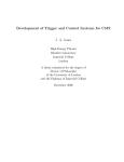
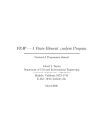
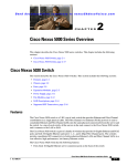
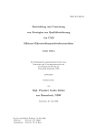
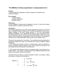
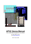
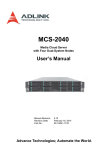
Augut 11, 2010 [RD51 SCALABLE READOUT SYSTEM] What is SRS short introduction , status and outlook 11 August 2010 The RD51 Working Group 5 activities on common electronics for a multichannel readout system started its design phase in 2009 with the compilation of a chip knowledge base as a common base for electronics requirements for RD51 users. The large variety in readout requirements (signal polarity, trigger concept, timing resolution, radiation tolerance, analogue versus digital, choice of readout bus, number of channels, power and packaging, bandwidth, data formats, online software) does not allow for a simple common solution, unless one designs a system with the following general properties: a.) common chip link interface for different readout chips on detector-resident hybrids b.) scalability from a small to a large system based on a common readout backend with link interfaces for specific fontends .) integration of commercial standards for a minimum of custom hardware modules between the chip frontend and the online system d.) default availability of a very robust and supported data acquisition package e.) flexibility to implement different readout architectures and trigger schemes CHIP Matrix https://espace.cern.ch/rd51-wg5/chipmatrix/default.aspx 1 Augut 11, 2010 [RD51 SCALABLE READOUT SYSTEM] The Scalable Readout System (SRS) implements the above requirements in the following practical framework: • • • test systems need a few channels /chips that can be connected to a turnkey and low -cost readout system with a standard Online system large system, like an LHC experiment, use the same readout backends but with a much larger number of frontend chips and frontend cards typically detectors need some special features, for this SRS allows for adapter cards to be integrated into SRS with application specific logic1. The first SRS system components consists of the following choices (from the top of the SRS block diagram below): A.) Common system components of SRS: • • • • • • • The DATE Online system of the ALICE LHC experiment, stable and user friendly: its use by RD51 is based on a MoU with the ALICE DATE team 10 Gigabit Ethernet as commercial, very high performance standard for readout links, based on copper or fibre. The Scalable Readout Unit (SRU) as a 40-fold DTC link concentrator between the frontend system and the 10Gigabit port of DATE ( not needed for small systems ) Programmable Front End Cards (FECs) that fit in a cheap, mechanical framework (6U x 220 Euro-card ) with PCIe connectors to interface adapter cards DTC link cables (CAT6) for transferring Data Trigger and Control between the FECs and the SRU A user-programmable trigger and clock interface based on LVDS and NIM logic on both SRU and FEC cards . TTC fibre interface on the SRU for trigger and timing distribution in LHC experiments B.) Shareable components for classes of chips ( analogue , digital, etc ): • • SRS adapter cards to interface different types of chips ( analogue, digital, mixed ) to the FEC card. Chip readout links (cables, fibres ) for distances of tens of meters between the FEC crate and the hybrids on the detector C.) Detector specific components: • • Chip hybrids with standard connectors (example: HDMI ) on the detector and on the readout side, allowing the user to choose the most suited readout chip Application-specific adapter cards in A, B or C format for user-defined purposes like diode bias control etc. By today, 14 month after approval in the RD51 CRETA meeting, Working Group 5 succeeded, with a strong support1 from users, teams and the management2, to build / integrate the following first basic SRS components for the prototype system implementation of first SRS systems: 2 DATE Online system ported to Gigabit Ethernet readout (UDP equipment type) Scalable Readout Unit built and revised with 40 DTC links, TTC chip, 10 GB Ethernet DTC links ( Data, Trigger and Control ) tested on Alice Calorimeter FEC cards common for all SRS systems with direct Gigabit Ethernet link ADC Adapter card for up to 16 analogue chips with 40 MHz@12 bit ADC HDMI-based chip link up to 20 m Hybrids with APV25 tested on a GEM for readout of Cosmics Augut 11, 2010 [RD51 SCALABLE READOUT SYSTEM] Logical overview over the scalable SRS architecture Footnotes: 1.) It is understood that users who design their own SRS system or adapter logic make the production files and firmware available to RD51 2.) Thank you for further help to commissioning the first small SRS systems on 2010 testbeams 3 Augut 11, 2010 [RD51 SCALABLE READOUT SYSTEM] Software packages: The default Online system for SRS is DATE that needs to be installed on a Server-PC running Scientific Linux 4. Users may also install the Root Data Analysis Framework and optionally Amore for data quality monitoring. Data Formats: The equipment type used by DATE is UDP, allowing to read CDH-formatted event data via one, or more Gigabit Ethernet ports of a PC. The sub-event hardware format is derived from the RHIC data format and remains invisible to DATE. Here we need a decoder software that allows, like the RHIC decoder, to identify the type of data and decode them according to this embedded information. Controls: For Front-end Control and Configuration, the FeC2 software of the DATE team can run on the same or another PC as DATE. FeC2 was written originally for the ALICE DDL link, to work over IP ports, to allow for selective broadcasting. Scripts can be used as self-contained sequences for initialization of runs. The addressing conventions between the user and the firmware are to be defined. Run control: The Data acquisition is deemed to be started in a READY state before the trigger is enabled, and the trigger should be disabled before the run is closed. This can be automatized like in ALICE via the ECS system, however initial small systems are deemed to take are about the sequence by the shifter. Readout Links: SRS readout links are Ethernet cables or fibres which are directly plugged to the Gbit Ethernet port of the online computer. On the electronics side these can either be connected directly to the SFP port of the FEC cards ( = small system) or, ( = large systems) to one of the four 5 Gbit/s SFP+ ports of the Scalable Readout Unit (SRU). In practise, a small system does not need the SRU since the SFP ports of a few FEC’s can be directly connected to the online DATE computer. The SFP+ standard for 10 Gigabit on the SRU allows using either cables (up to 7 m) or fibres (length > 100 m depends on fibre choice). The SFP plug on the FEC cards can be equipped with cable adapter for using standard CAT6 network cables. Scalable Readout Unit: . When the system is to be increased to more than a dozen FEC cards, a Scalable Readout Unit (SRU) with 40 DTC link ports has to be added in order to allow connecting up 4 Augut 11, 2010 [RD51 SCALABLE READOUT SYSTEM] to 40 FECs to the Gigabit output network between the SRU and the online computer. The SRU has 4 SFP+ ports of 5 Gigabit/s each. A user-defined clock and trigger interface, based on NIM and LVDS signals allows to adapt SRS to different trigger concepts. For LHC applications, the SRU has a TTCrx chip to pick up the LHC clock and triggers ( L0,L1, L2a, L2r) via the fibre network. Larger systems, or systems with aggregate readout bandwidth above the capability of a single SRU require several SRUs outputs to be interconnected via an optical switch in front of the Online PC farm. Trigger architectures: A priory, SRS does not take assumptions about a specific trigger architecture. The DTC links can carry trigger level signals up to a chip or to a FEC card, or it can return trigger signals to the SRU where the desired trigger concept can be implemented in firmware. The SRU, apart from its TTC interface, has both NIM and LVDS I/O allowing to interface with external trigger, clock and busy logic. DTC links: A DTC link is a shielded CAT6 cable with an SRS specific protocol that carries Data, Trigger and Control information between the SRU and the FEC cards. FEC Crate: Up to 14 FEC cards fit in one 6Ux220 Euro-chassis, each FEC card being interfaced to Adapter cards in the same slot. The Chassis can be mechanically configured to carry a mix of A, B or C type adapter cards. Adapter cards: Adapter cards can be built in 3 different form-factors (A,B,C) and primarily interface the chip link to the FEC card. The programmable interface is implemented via PCIe connectors that provide very high speed links, programmable I/Os, I2C controls and HV/LV Power. The chip link adapter ( analogue or digital versions) connects N chips with the one FEC. Extension adapters can de designed for detector specific purposes (example: HV bias control for APD’s or SiPM’s ). Depending on the real estate and I/O requirement: there are 3 different adapter sizes (A, B or C) The first chip adapter designed by RD51 is for analogue chips ( i.e. APV25, Beetle etc ) . Up to 8 HDMI chip links can connect up to 16 chips on one ADC adapter. Digital chips (like VFAT) require a conceptually simpler chip adapter which can be designed on request from a team. Further adapters are currently under design by the NEXT and ATLAS MAMMA collaborations. Chip links: Amongst the many possibilities for implementing a chip link, SRS has chosen the industry HDMI cable and connector standard for the first hybrids. The HDMI cables provide very high bandwidth over distance as well as power at low cost. Further link standards may be implemented later if required. Chip hybrid: A readout chip resides on a micro-etched hybrid PCB that gets plugged on the detector. It connected via a chip link to an adapter of the FEC crate. This feature allows changing or mixing the readout chip whilst maintaining the SRS backend ( different firmware may be required ). The first chip chosen is the 128 channel, analogue APV25 chip. The APV hybrid has a HDMI link interface and can be extended to a dual hybrid with 256 channels. First SRS Data with APV hybrid on a GEM 5 Augut 11, 2010 [RD51 SCALABLE READOUT SYSTEM] Mai 2010: LEFT: Offline reconstructed data from APV hybrid on a GEM with cosmics APV25 chipHybrid->HMDI-link->ADC12bit@40 MHz –>Virtex-5-FPGA->Root analysis. Semi-gaussian pulse shape of cosmic particles and their cluster size. RIGHT: Amplitude distribution and cluster size distribution. More details see Sorin Martoiu’s talk. Illustrated details and status of SRS this appendix will be regularly updated... Frontend Hybrid APV25 (EDMS Reference EDA-02075-V2) . Fig. 1: Top left: Photo of the first RD51 hybrid (Mai 2010) with a wire-bonded, rad-hard APV25 chip with 128 channels. The bonding pitch is 88 micron on 4 row pads. Standard RD51 hybrids have a 130 pin connector for MPGD’s detectors, a mini HDMI connector for readout, and an optional flat cable connector for extension to a 2nd hybrid. Local LDO’s and PLLs provide the voltages and clocks required by the chip. Top right: Photo of the bonding area between 128 pads of the APV chip and the micro-etched bonding pads of the APV carrier board. Bottom left: The hybrid contains ESD diodes of less than 1pF capacitance and is to be grounded via lateral MMCX connectors for the chamber ground, serving also as a snap-in fixation of the hybrid. The hybrid can be configured for AC or DC coupling and as a master or slave device for daisy-chained readout of 2 hybrids via 1 HDMI cable. Bottom right: Photo of the APV hybrid mounted on a GEM chamber. The lateral MMCX connector brings the chamber ground to the hybrid. First data taken with this hybrid are shown above. Below: Two APV hybrids ( master and slave version) can be read out via a single HDMI cable. The two hybrids get connected via a short extension flat cable. 6 Augut 11, 2010 [RD51 SCALABLE READOUT SYSTEM] APV hybrid details Chip link between hybrid and FEC card 7 Augut 11, 2010 [RD51 SCALABLE READOUT SYSTEM] Fig.2 : In this example, frontend hybrids are connected via HDMI link cables to a SRS link adapter over up to 20 m. Shown is an originally planned small, A sized- ADC card. For better integration density however WG5 preferred to design an ADC card of size C ( full-size like FEC card ) which can receive 8 HDMI cables (16 hybrids). Bottom: HDMI connector on hybrid and adapter and the transmission issues for the adapter card. For more info, see the Freiburg talk of Sorin Martoiu. Adapter card (ADC) for 16 analogue Chips 8 Augut 11, 2010 [RD51 SCALABLE READOUT SYSTEM] Fig. 3 : TOP: Photo of the ADC adapter card, 12 cards produced in July 2010 Bottom: Slide on adapter for analogue chip links. 9 Augut 11, 2010 [RD51 SCALABLE READOUT SYSTEM] FEC card interface with C-adapter card Both FEC and ADapte cards fit in the same Eurocrate slot, with front panels on both sides. The interface chosen for SRS are three PCIe connectors. These provide power from the FEC card, high speed I/O and I2C control for the adapter card resources. 10 Augut 11, 2010 [RD51 SCALABLE READOUT SYSTEM] First tests with FEC and ADC Adapter for APV hybrid First digitized APV signals ( test pulse mode) recorded by the FEC card via the HDMI link and ADC adapter card. “ABC” of the adapter cards for the SRS system 11 Augut 11, 2010 [RD51 SCALABLE READOUT SYSTEM] Fig.4: The FEC card can be interfaced to 3adapter card formfactors (A,B C) and via 3 type of connectors connectors PCIeX1, PCIeX8, PCIeX16. The relative sizes and combinations of A , B and C cards relative to the FEC card are shown. Users who want to design their own A, B or C cards, please contact us to receive the exact 3D outlines and connector positions to fit with the FEC card. For the pinout and interface specifications we will prepare a document, ad interim our reference designs ( FEC card and C card ) can be used. Below: View of the straddle-mount PCIe connectors that connect the A-B-C cards to the EFC card. FEC Frontend Card Fig 5: Photo of the 1st FEC card by UPV Valencia with SFP connector for Gigabit Ethernet, two RJ45 connectors for DTC links and/or daisy chaining, power connectors for LV and HV and the 3 straddlemount PCIe connectors for A, B or C-size adapter cards. The functionality of the FEC is based on 12 Augut 11, 2010 [RD51 SCALABLE READOUT SYSTEM] firmware for a Xilinx Virtex-5T FPGA with added DDR2 memory buffer. First FEC cards have been produced and will be tested with readout firmware via Gigabit Ethernet and DATE in July/August 2010 at CERN. BELOW: Connectivity details of the EFC card. A user manual will be made available Jose F. Toledo of by UPV Valencia Fig 6: 13 Augut 11, 2010 14 [RD51 SCALABLE READOUT SYSTEM] Augut 11, 2010 [RD51 SCALABLE READOUT SYSTEM] Scalable readout Unit (SRU) Fig.7: Top: Design view of the new Scalable Readout Unit (SRU). The SRU is needed for large systems with more than ~ a dozen FEC cards and >16 k Channels. The co-design at CERN and CCNU Wuhan for a new SRU integrates new 40nm Virtex-6 technology with four 5 Gigabit Ethernet output ports and 40 DTC inputs. A DDR3 memory buffer extends the SRU’s event-buffer storage capacity to several Gigabytes. A general-purpose NIM and LVDS interface provides the user with all options for building a trigger and busy logic with external devices. A TTC chip interface has been added for LHC clock and trigger applications. July 2010: New SRU’s are under design revision and expected by 10/2010. Bottom left: SRU Front-panel with 40 DTC links to the FEC cards. Bottom right: Back view of the SRU with 4 SFP+ ports that can be used either with 10 Gigabit Ethernet copper or fibre links. Below top: The SRU has a fast, user-defined pulse interface for 100 OHM LVDS or 50 OHM NIM signals. These signals are connected to the FPGA and can therefore be injected to the DTC links, for examples as readout trigger for the frontend chip. Inversely, triggers generated by the Frontend electronics can be sent out as common trigger. Other applications are trigger-BUSY generation or event counting. 15 Augut 11, 2010 [RD51 SCALABLE READOUT SYSTEM] PHOTO of the first SRU version March 2010 16 Augut 11, 2010 17 [RD51 SCALABLE READOUT SYSTEM] Augut 11, 2010 [RD51 SCALABLE READOUT SYSTEM] Photo of a FEC and ADC adapter card in a Eurochassis slot 18 Augut 11, 2010 [RD51 SCALABLE READOUT SYSTEM] Fig.8: Top: Part references for the 6Ux220 Euro-crate used for SRS electronics. Bottom Left: View of a SRS Euro-chassis with 1 FEC card inserted from the back side and full sized C card adapter inserted from the front side. Bottom Right: View of an SRS Euro-chassis with 1 FEC inserted from the front side and two half-sized A and B cards inserted from the back side. A support bar with card guides is mounted in order to give mechanical support to the A and B cards. Crates with partial support bars can combine C card sections and A+B side sections. Fig. 9: TOP: ATX power adapter for SRS sytems. The LV power for the SRS systems ( SRU, FEC card ) are provided via standard ATX power units, with additional options for user -provided power. The power adapter/filter has a variety of user-configurable options and is fused on each LV cable by Mini car fuses. All ATX power lines are passed though EMI filters and SRS Voltages 4.2 V and 1.8 Volt are provided. For user-defined power, a AC adapter can be added to the ATX power box. Note: High voltage (up to +500V) get directly connected to the 2 pin connector on the FEC front panel. BOTTOM: The ATX power pack and the ATX Adapter filter can get attached to the crate in the way shown below. 19 Augut 11, 2010 [RD51 SCALABLE READOUT SYSTEM] DATE performance with Gigabit Ethernet ( UDP equipment) 20 Augut 11, 2010 [RD51 SCALABLE READOUT SYSTEM] packet size 16000 bytes 500 400 throughput (MB/s) 300 200 100 0 0 50000 100000 150000 200000 payload size (bytes) 250000 300000 350000 Fig.10 : DATE scalability test status July 2010 ( Filippo Costa) test with 1 UDP equipment : the readout throughput of 3.6 Gbit/s is reached above 80 kbyte (event) payload using 16 kbyte UDP packets. For example: Event size 80 kB, Trigger rate 5 kHz and 420 Mbyte/s throughput ( error-free over 50 Million events) 21