1
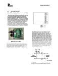
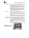
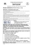
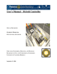
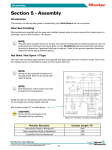
2.2.A.8.
Data Acquisition System
Series 6000 Data Acquisition System (6000DAS), shown in Fig. 1, is a high
performance transducer signal conditioning, digitization and control system. It
uses analog, digital and software technology to condition, acquire, display and
analyze transducer and digital signals and provides digital and analog outputs for
control.
PI660-6000 is the application software that
operates the Pacific Instruments Model 6000
Data Acquisition System (DAS). It is a
turnkey application that controls channel
setup, acquisition of data, storage of data to
disk, data conversion to engineering units,
and export of data to common file types. The
software operates under Microsoft Windows.
The specifications of the system are provided
in the Pacific Instruments’s manuals entitled
‘PI660-6000 Data Acquisition and Display
Software’ and ‘6000DAS: Transducer Data
Acquisition and System Control’, Section 1.
Fig. 1 Series
6000
Data
Acquisition System.
The details on installation and operation of
the Pacific Instruments Model 6000 Data
Acquisition System are presented in
‘6000DAS: Transducer Data Acquisition and
System Control’, Section 2.
User’s manual on warnings, alarms and
triggering is provided in the Pacific
Intruments manual (‘6000DAS: Transducer Data Acquisition and System
Control’, Section 3).
2. 2. A. 8. a. Introduction and Product Description
The 6000 DAS’s unique architecture enables efficient recording of both static and
dynamic measurements with excellent time correlation. Operating software is
available for Windows 95 and NT for use with personal computers or the
system’s high level GPIB command language may be used for programming with
other types of computers.
The system architecture accommodates up to 4096 channels in a single system.
Multiple systems may be connected to a single IEEE-488. The 6000DAS comes
in two sizes. Model 6000 mainframe and 6001 slave enclosures hold 16
input/output modules and mount in EIA 310C 19-inch racks requiring 14-inches
height. The 6010 mainframe is a 5-¼ inch bench top case that holds 3
input/output modules and is mounted on the same rack.
The system is modular to accommodate applications of different size and
transducer types. All systems employ a Mainframe as the basic system interface
hardware. The channel modules provide transducer signal conditioning and
digitizing. Up to 16-channel modules mount in the 6000 Mainframe and 6001
Slave enclosures and each system may have space for up to 512 channel
modules.
The 6000 system is designed for large and small scale testing for both long and
short duration. Its flexible design allows for the sampling of different channels at
different rates, and it allows for the decimation of data being acquired during long
duration testing. The system has two parallel buffers for digitised data. One of
the buffers is a FIFO buffer, and the other is a ring buffer. The ring buffer can be
programmed to capture pre and post trigger data and can be operated at
different speeds than the FIFO. The FIFO sends data to the computer in real
time at a maximum throughput of 800,000 samples per second.
As an example, consider a test of an aircraft fuselage. The test may take two
weeks to perform, and it may culminate in failure of the fuselage. The user can
program the FIFO to record data to disk for historical purposes at a low rate (1
scan per minute), and program the ring buffer to run at a high rate (1,000 scans
per second). During the non-failure testing of the fuselage data are logged to
disk without filling up the drive. When the failure occurs the ring buffer triggers
and captures the programmed amount of pre and post trigger data at the high
rate.
The software for the 6000 system is PI660. It uses open architecture
approaches that allow for the extension of the software and easy integration into
user facilities. Test parameters are stored in an Access database and are
retrieved and modified via the Open Database Connectivity Layer (ODBC) using
SQL commands. The user can choose to use a different database type (i.e.
Paradox, Oracle, etc.) as long as it is supported by ODBC (most are). If the
database software changes version PI660 is shielded from the change due to the
open architecture read and write architecture of ODBC.
PI660 also is easily integrated into user facilities. The mechanism that gives
PI660 this capability is known as the User Code Interface (UCI). PI660 is a full
turnkey software package for the 6000 and 5500 systems, but often the systems
are used in conjunction with other products from other vendors (i.e. PLCs,
sequencers, etc.). The UCI provides the means to modify the behaviour of
PI660, insert menu commands, control PI660, etc. The UCI is really a shared
memory DLL that PI660 makes calls to during operation. The calls are to
functions in the DLL that PI660 knows about. Since the user receives the source
code for the DLL (and a fully operational version of the DLL) he is free to add
functions to the DLL. The DLL can also be used as a middle ground between
Graphical Programming Languages (GPLs) such as LabView and HP Vee or
between PI660 and user applications.
The 6000DAS is a programmable, multi-channel transducer and digital input
signal conditioning and recording system that includes digital and analog outputs
for test and facility control. All channel and system functions and parameters are
programmable using the IEEE-488 computer interface installed in the Mainframe.
The mainframe also contains the data output interface that may be IEEE-488 or
optional PCM (IRIG 106) format.
Series 6000 products are unique in that they are calibrated entirely by computer.
A non-volatile memory on the channel modules is programmed at the factory with
values that calibrate excitation, gain and analog-to-digital converter (ADC).
These values are loaded and initialised when the system is powered up. There
are no user controls or calibration adjustments. Field or customer calibration is
done using Pacific’s service and calibration software.
2. 2. A. 8. b. Hardware of Model 6000 Data Acquisition System
2.2.A.8.b.1.
Mainframe and Enclosures
A 6000DAS is comprised of a Mainframe and a Slave enclosure; the number of
slave enclosures can be extended up to 31. Two models of Mainframe
enclosures (6010 and 6000) have slots for three or sixteen I/O modules (cards).
Slave enclosures have slots for sixteen I/O modules. The Mainframe contains an
IEEE-488 control and data output interface. Slaves are connected to the main
frame by supplied cables.
The Model 6000 Mainframe shown in Figs. 2 and 3 is for larger systems. It holds
the initial 16 channel modules with the remaining 16 channel modules being
placed in 6001 Slave enclosures. Both are line powered, 8U (14 inches) high
rack mounted enclosures.
Fig. 2 Mainframe 6000 (door closed)
Fig. 3
Mainframe
removed)
6000
(door
For smaller systems there is the 6010 Mainframe, which holds 3 channel
modules. It is line powered and 3U (5 ¼ inches) high. The 6010 is supplied in a
bench top case, but can be mounted in a 19-inch rack using an optional kit. Like
it’s larger counterpart, 6010 based systems may be expanded using 16-slot
Slave enclosures.
Mainframes include and IEEE-488 control and data interface a system/channel
controller module with Digital Data Selector (DDS) and front panel with LED
indicators. Standard mainframes have an IEEE-488 data interface. A serial PCM
data interface is optionally available.
A microprocessor, which is located on the channel controller module, programs
and controls channels in the enclosure. It programs the channel’s operating
parameters in response to computer instructions and at power up. It also
controls channel functions such as autobalance, autozero, calibration and data
output. Operating parameters are stored in a non-volatile memory on the
channel controller that is read during the power up sequence and initializes
channels. This enables the channels to power up with their last programmed
parameter values.
The front panel doors on both mainframe and slave enclosures may be removed
for module insertion and wiring. An internal cable trey routes input and output
cables to the rear of the enclosure where they exit through the rear panel. The
rear panel has connectors for interface, control and calibration connectors as well
as AC power. Integral fans provide cooling to the input/output modules, drawing
air from the rear through a filter on the rear panel.
Input/output modules have front mounted connectors that interface to
transducers and control circuits. They are located approximately 3 inches behind
the door giving ample room for mating connectors and cabling. Cabling runs
from the rear, through the integral cable tray, turning downward to the mating
connector, which is supplied with a hood having a 90° cable exit. The input
cables may directly wire to the transducer or junction boxes may be used.
Junction boxes provide screw terminals for terminating facility input cables.
The mainframe or slave enclosure provides DC power to the input/output
modules.
2.2.A.8.b.2.
Input/Output Modules
Signal conditioning input modules are available for the measurement of strain,
temperature, acceleration, displacement, voltages, currents, digital events, IRIG
time, frequencies, periods, and counts. Output modules are available to provide
TTL or relay outputs and DAC outputs. Any module can be placed in any
available card slot in a mainframe or slave enclosure.
Channel modules do one of four functions:
(1) Condition and digitize transducer or other analog signals,
(2) Condition and record the status of digital inputs,
(3) Provide digital outputs for system, test or facility control and
(4) Provide filtered analog (DAC) outputs for controlling test equipment or
system calibration.
The 6032-275 channel modules were supplied and installed in the Mainframe
6000 and Slave 6001. The 6010 enclosure consist of two 6013-3 cards and one
6093 card.
2.2.A.8.b.2.1 Model
6032
4-Channel
Transducer
Amplifier-
Digitizer
The 6032 input module (shown in Fig. 4) has four channels of high performance
strain gage or bridge transducer signal-conditioning amplifier and 4-pole lowpass filter. The high level outputs are multiplexed and digitized to 16 bits then
output to the 6000 data bus. In addition to the digitized output, each channel
provides a continuous, wideband analog output. Excitation monitor channels that
digitize and output the excitation voltage are optional.
Some features the make the 6032 4-Channel Transducer Amplifier-Digitizer
unique are:
− Programmable excitation, 0 to 12 Volts
− Eight-wire input with remote sensing
− Optional excitation monitor channels
− Programmable configuration for ¼, ½, and full bridges
− Shunt calibration
− Automatic zero and balance
− Gains 1 to 5,000 with 0.05% resolution
− Voltage calibration
− 15K channel digitizing rate with 16-bit resolution
− 4-Pole low-pass filter, optionally programmable
− Continuous analog outputs
− Programmable warnings and alarms.
The 6032 occupies one
slot in a Series 6000
mainframe or slave
enclosure. Power and
control/data
bus
connections are made
though two connectors
to
the
enclosure’s
backplane.
Inputs
connect to a 50-pin
type D connector on
the front card edge.
Outputs are on a 9-pin
type D connector also
on the front edge of the
card module.
The details on preinstallation
configuration of the
6032, installation of the 6032 in mainframe and slave enclosures, connecting the
6032 to transducers and outputs, programming the 6032 using PI660, can be
found the manual provided by Pacific Instruments (‘6000DAS: Transducer Data
Acquisition and System Control’, Section 8).
Fig. 4 Model 6032 4-Channel Transducer AmplifierDigitizer.
2.2.A.8.b.2.2 6013
Amplifier-Digitizer
Termocouple,
Voltage
Instrumentation
The 6013 has eight channels of DC-coupled programmable gain instrumentation
amplifier, filter and sample & hold. The high level output signals are multiplexed
into a 16-bit analog to digital converter and output to the 6000’s data bus. It is
used for thermocouples, DC LVDTs and other voltage output transducers.
A circuit measures and digitizes temperature of a remote sensor at the
thermocouple terminations. PI660 software uses this measurement to cold
junction compensate thermocouple readings.
Calibration may be performed by substituting a precision input from a traceable
source. Inputs can be switched to the 6000’s voltage calibration bus and
attenuated to match gain settings. More detailes on the card are provided in the
Pacific Instruments’ Manual (‘6000DAS: Transducer Data Acquisition and
System Control’, Section 4).
2.2.A.8.b.3.
GPIB Instructions
Series 6000 is programmed by computer using the IEEE-488 interface and a
high level GPIB instruction set.
The system controller, which is mounted in the Mainframe, converts the high
level GPIB instructions into low level, hardware specific primitive commands
which are distributed to the channel controllers and DDS. In the channel
controller the primitive commands are implemented or passed on to the
input/output modules. Operating parameters; i.e. gain and filter frequency, are
stored in the channel controller for power-up programming. The channel
controller implements control operations; i.e. autobalance and autozero, and the
results stored and passed to the input/output modules.
The details on the GPIB programming are provided in the Pacific Instruments’
manual entitled ‘6000 System Programming Primer’.
2. 2. A. 8. c. PI660-6000 Application Software
PI660-6000 is available in a standalone version or in a client server version. The
client server version supports a single server (connected to the 6000 DAS) and
up to ten client display workstations. The client server version uses standard
Ethernet interfaces and requires Windows NT.
One of the most unique features of PI660 is its open architecture. In its simplest
form it is a turnkey application that performs all of the tasks of system control,
data acquisition, display, and data exportation. Internally, however, PI660 is
much more than a turnkey application.
PI660 is comprised of two functional parts. The first part is the main screen or
container application. The second part is a dynamic link library (DLL). The
container application examples shipped with the CMD are written for Visual
Basic, Lab View, and Microsoft Excel. The user can create other container
applications in any programming language. The figure above shows the
Microsoft Excel container application working with the DLL to provide real time
spread sheet updates based on data from a Pacific Instruments 6000 DAS.
The Component Module DLL concept provides the user with a driver to the
turnkey application code. This is in contrast to providing the user with a driver to
a piece of hardware. The user spends his development time changing the user
interface and customizing the display environment so that it fits his facility’s
needs.
The detailed manual for the PI660 application software is provided by Pacific
Instruments (‘Using PI660 Version 8: An Operator’s Guide To Data Acquisition
Using The Pacific Instruments Model 6000 DAS’).
2.2.A.8.c.1.
Two Add-On Capabilities for the PI660-6000
There are two add-on capabilities for the PI660-6000 software. They are the
math engine and the component module DLL (CMD).
2.2.A.8.c.1.1 PI660-6000 Math Engine
The PI660 Math Engine is an add-on capability. It allows the user to define up to
300 equation channels. The equation (computed) channels are updated in real
time and are available for display on the PI660 data displays.
The math engine provides a programming language syntax that allows the user
to define complex equations. The syntax of the language provides for single
point based calculations. There is no looping structure to the language. Users
can generate loop structure calculations using the Component Module DLL
(CMD).
Each computed channel can be derived from up to nine other channels. The
nine other channels can be either real inputs to the 6000 system hardware or
other computed channels. A computed channel consists of an equation, a name,
a unit tag, two alarm levels, two warning levels, and colors for alarm, warning,
and good data levels.
2.2.A.8.c.1.2 Component Module DLL (CMD)
The CMD is a programming interface to the PI660-6000 software. It allows the
user to extend, rearrange, add, and remove features from the PI660-6000
turnkey software. It is a much more flexible programming environment than a
simple driver. It is actually a driver to a turnkey application rather than a
hardware driver, and as such it provides for extremely fast facility based software
integration. The math engine is described in Section 2 of the PI660-6000
Software Specifications Sheet. The Component Module DLL is described in
Section 3 of the PI660-6000 Software Specifications Sheet.